JP4699085B2 - Electric compressor for vehicles - Google Patents
Electric compressor for vehicles Download PDFInfo
- Publication number
- JP4699085B2 JP4699085B2 JP2005142370A JP2005142370A JP4699085B2 JP 4699085 B2 JP4699085 B2 JP 4699085B2 JP 2005142370 A JP2005142370 A JP 2005142370A JP 2005142370 A JP2005142370 A JP 2005142370A JP 4699085 B2 JP4699085 B2 JP 4699085B2
- Authority
- JP
- Japan
- Prior art keywords
- electric compressor
- electric
- refrigerant
- vehicle
- compressor
- Prior art date
- Legal status (The legal status is an assumption and is not a legal conclusion. Google has not performed a legal analysis and makes no representation as to the accuracy of the status listed.)
- Expired - Fee Related
Links
Images


Description
本発明は、電気自動車等の車両用空調装置に使用される車両用電動圧縮機に関するものである。 The present invention relates to a vehicular electric compressor used in an air conditioner for a vehicle such as an electric vehicle.
近年、電気自動車やハイブリッド自動車のように、電気の動力を利用して走行する車両の開発及び市場への投入が急速に進んでいる。このような車両に装備される車両用空調装置では、従来の内燃機関で走行する車両とは異なり、冷媒を圧縮して送出する圧縮機の駆動にも電気を動力として利用する電動圧縮機が採用されている。
このような電動圧縮機は、圧縮機構及び電動機を同じハウジング内に内蔵する密閉型圧縮機の構成が一般的に採用されている。さらに、車両用空調装置の電動圧縮機は、電源から入力された電力を電動機に供給して運転制御を行うインバータ制御装置を備え、このインバータ制御装置は、圧縮機とは別体に設置されている。
2. Description of the Related Art In recent years, vehicles that use electric power, such as electric vehicles and hybrid vehicles, have been rapidly developed and introduced into the market. In such a vehicle air conditioner equipped in such a vehicle, an electric compressor that uses electricity as power for driving a compressor that compresses and sends out refrigerant is employed, unlike a vehicle that runs on an internal combustion engine. Has been.
Such an electric compressor generally employs a hermetic compressor configuration in which a compression mechanism and an electric motor are housed in the same housing. Furthermore, the electric compressor of the vehicle air conditioner includes an inverter control device that performs operation control by supplying electric power input from the power source to the electric motor, and this inverter control device is installed separately from the compressor. Yes.
また、インバータ制御を行う冷凍装置(特に、空気調和機の室外機)の従来技術としては、冷凍装置及びインバータ装置を小型化するとともに、冷凍サイクルの信頼性向上を目的として、インバータ等を実装した基板のパワー半導体面にゲルを充填することが提案されている。この従来技術では、ゲルの充填によりパワー半導体素子が保護され、さらに、ゲル表面を樹脂封入することにより絶縁されるので、パワーモジュールの信頼性が向上するとされる。(たとえば、特許文献1参照)
ところで、車両用空調装置に使用される車両用電動圧縮機(以下、「電動圧縮機」と呼ぶ)は、車両走行用の駆動力を発生させる電動機や発電機駆動用の内燃機関等とともにエンジンルーム内に設置される。このため、高温の放射熱や振動の影響を受けやすい設置環境となり、インバータ制御装置を構成する各種の電気・電子部品(たとえば、パワー素子やコンデンサ)等を周囲環境から保護して動作を保証するためには、冷却構造や振動対策が必要となる。
また、エンジンルーム内に設置される機器類は、−40℃程度の低温から百数十℃程度の高温まで大きな温度変化を伴う環境での使用に耐える必要があるので、特に、インバータ制御装置等の電気機器類については、結露等により発生する水滴に対する対策も必要となる。
Incidentally, a vehicular electric compressor (hereinafter referred to as an “electric compressor”) used in a vehicular air conditioner is an engine room together with an electric motor that generates a driving force for driving a vehicle, an internal combustion engine for driving a generator, and the like. Installed inside. As a result, the installation environment is easily affected by high-temperature radiant heat and vibration, and various electrical and electronic components (for example, power elements and capacitors) that constitute the inverter control device are protected from the surrounding environment to guarantee operation. Therefore, a cooling structure and vibration measures are required.
In addition, the equipment installed in the engine room must withstand use in an environment with a large temperature change from a low temperature of about −40 ° C. to a high temperature of about several hundreds of degrees Celsius. For these electrical devices, it is necessary to take measures against water droplets generated by condensation.
このような背景から、車両用空調装置に使用される電動圧縮機は、信頼性や耐久性を確保するため、放射熱、振動及び水滴に対する対策が必須条件となる。
本発明は、このような事情に鑑みてなされたものであって、放射熱、振動及び水滴に対する対策が施された車両用電動圧縮機を提供することを目的とする。
From such a background, measures for radiant heat, vibration, and water droplets are indispensable for the electric compressor used in the vehicle air conditioner in order to ensure reliability and durability.
This invention is made | formed in view of such a situation, Comprising: It aims at providing the electric compressor for vehicles by which the countermeasure with respect to a radiant heat, a vibration, and a water droplet was given.
上記課題を解決するために、本発明は以下の手段を採用する。
本発明の請求項1に係る車両用電動圧縮機は、電動機により圧縮機構を駆動して車両用空調装置の冷媒を圧縮する車両用電動圧縮機において、前記電動機を制御する制御装置の制御機器類を収納設置する筐体内に、CPUやパワー素子等の発熱量の大きい電装部品の高さのみまで絶縁ゲル剤を充填したことを特徴とするものである。
In order to solve the above problems, the present invention employs the following means.
A vehicular electric compressor according to claim 1 of the present invention is a vehicular electric compressor in which a compression mechanism is driven by an electric motor to compress refrigerant in a vehicular air conditioner. In this case, the insulating gel agent is filled only to the height of the electrical component having a large calorific value such as a CPU or a power element.
請求項1に記載の車両用電動圧縮機によれば、電動機を制御する制御装置の制御機器類を収納設置する筐体内に、CPUやパワー素子等の発熱量の大きい電装部品の高さのみまで絶縁ゲル剤を充填したので、絶縁ゲルに覆われた筐体内の電機部品は、電気的に絶縁されるとともに水滴の侵入が防止される。さらに、絶縁ゲルに覆われた筐体内の電機部品は、基板等の振動が低減され、振動により固定用のビス等が緩むことも防止される。
According to the electric compressor for a vehicle according to claim 1, only the height of electrical components having a large calorific value, such as a CPU and a power element, is housed in a housing that houses and installs control devices of a control device that controls the electric motor. Since the insulating gel agent is filled, the electric parts in the casing covered with the insulating gel are electrically insulated and water droplets are prevented from entering. Furthermore, in the electrical parts in the housing covered with the insulating gel, the vibration of the substrate or the like is reduced, and the fixing screws and the like are also prevented from loosening due to the vibration.
請求項1に記載の車両用電動圧縮機においては、前記制御装置が、前記圧縮機構を収納するハウジングの低圧冷媒室に密接して設置されていることが好ましく、これにより、低圧冷媒室内の低温ガス冷媒により制御装置の電装部品を冷却することができる。なお、インバータ制御装置においては、特に、発熱量の大きいパワー素子や冷却することが好ましいコンデンサ等を効率よく冷却する配置が好ましい。 In the vehicular electric compressor according to claim 1, it is preferable that the control device is installed in close contact with a low-pressure refrigerant chamber of a housing that houses the compression mechanism. The electric component of the control device can be cooled by the gas refrigerant. In the inverter control device, an arrangement that efficiently cools power elements that generate a large amount of heat, condensers that are preferably cooled, and the like is particularly preferable.
また、請求項2に記載の車両用電動圧縮機において、前記低圧冷媒室は、冷媒を取り入れるための冷媒取入口が連通して設けられ、前記電装部品はパワー素子を含み、前記パワー素子は、前記冷媒取入口に近い位置に配置されていることが望ましい。
また、請求項2または3に記載の車両用電動圧縮機において、前記圧縮機構を収納する前記ハウジングは、有底円筒形状であることが望ましい。
Further, in the vehicle electric compressor according to
Moreover, in the electric compressor for vehicles according to
本発明の車両用電動圧縮機によれば、電動機を制御するインバータ制御装置等の制御装置を構成する制御機器類は、筐体内に収納設置された電装部品が絶縁ゲル剤により覆われているので、筐体内の電機部品は、電気的に絶縁されるとともに水滴の侵入が防止され、さらに、振動の影響を低減することもできるようになる。
また、制御装置を低圧冷媒室内の低温ガス冷媒で冷却するようにしたので、たとえばインバータ制御装置においては、パワー素子やコンデンサ等の効果的な冷却が可能となる。
従って、インバータ制御の車両用電動圧縮機をエンジンルーム内に設置しても、高温、高湿及び高振動の設置環境に対応し、信頼性や耐久性が向上するという顕著な効果が得られる。
According to the vehicle electric compressor of the present invention, the control equipment constituting the control device such as an inverter control device for controlling the electric motor is such that the electrical components housed and installed in the housing are covered with the insulating gel agent. The electric parts in the housing are electrically insulated, water droplets are prevented from entering, and the influence of vibration can be reduced.
Further, since the control device is cooled by the low-temperature gas refrigerant in the low-pressure refrigerant chamber, for example, in the inverter control device, it is possible to effectively cool the power element, the capacitor, and the like.
Therefore, even if the inverter-controlled vehicle electric compressor is installed in the engine room, it is possible to obtain a remarkable effect that the reliability and durability are improved in response to the installation environment of high temperature, high humidity and high vibration.
以下、本発明にかかる車両用電動圧縮機の一実施形態について、図1ないし図3を参照して説明する。
本実施形態で説明する車両用電動圧縮機は、たとえば電気自動車やハイブリッド自動車のように、電気の動力を利用して走行する車両に装備される車両用空調装置の冷媒回路に使用される。この車両用電動圧縮機は、低温低圧のガス冷媒(吸入冷媒)を圧縮して冷媒回路に送出する圧縮機構を駆動するため、電気を動力として利用する電動機を採用したものである。
このような車両用電動圧縮機(以下、「電動圧縮機」と呼ぶ)1は、たとえばスクロール圧縮機構等の圧縮機構(不図示)及び電動機(不図示)を同じハウジング2内に内蔵する密閉型圧縮機の構成が一般的に採用されている。また、このような電動圧縮機1は、電源から入力された電力を電動機に供給して運転制御を行うインバータ制御装置10を備えている。このインバータ制御装置10は、電動圧縮機1のハウジング2に密接して一体的に設置されている。そして、インバータ制御装置10は、インバータ制御装置10に給電を行う給電部20と、インバータ制御装置10及び給電部20の動作を制御する電源制御装置21と電気的に接続されている。
Hereinafter, an embodiment of an electric compressor for a vehicle according to the present invention will be described with reference to FIGS. 1 to 3.
The vehicular electric compressor described in the present embodiment is used in a refrigerant circuit of a vehicular air conditioner installed in a vehicle that travels using electric power, such as an electric vehicle or a hybrid vehicle. This electric compressor for vehicles employs an electric motor that uses electricity as power to drive a compression mechanism that compresses low-temperature and low-pressure gas refrigerant (intake refrigerant) and sends it to a refrigerant circuit.
Such a vehicular electric compressor (hereinafter referred to as “electric compressor”) 1 is a hermetically sealed type in which a compression mechanism (not shown) such as a scroll compression mechanism and an electric motor (not shown) are built in the
ハウジング2は、軸線を略水平にして設置される中空円柱形状をなしている。
具体的に説明すると、ハウジング2は、図1及び図3に示すように、一端に開口部を有し内部に電動機が収納される有底円筒形状の第一収納部(ハウジング本体)2aと、一端に開口部を有し内部に圧縮機構が収納される有底円筒形状の第二収納部(蓋部)2bとに二分割されている。第一収納部2a及び第二収納部2bは、互いの開口部どうしを向かい合った状態にして接合し、両開口部に設けたフランジ部をボルト・ナット等により着脱可能に固定して一体化されている。
The
Specifically, as shown in FIGS. 1 and 3, the
本実施形態では、第一収納部2aの内部に図示しない圧縮機構の低圧冷媒室が形成されており、第一収納部2aの外周面には、内部の低圧冷媒室に連通する冷媒取入口3が設けられている。この低圧冷媒室は、冷媒取入口3を介して車両用空調装置の冷媒回路に連結され、室内熱交換器または室外熱交換器を通過して気化した低温低圧のガス冷媒が送り込まれるようになっている。
すなわち、第一収納部2aの外周面及び底面は、特に、冷媒取入口3の近傍部分が吸入冷媒である低温低圧のガス冷媒によって冷やされるため、ハウジング2の他の部分に比べて低温となる。
In the present embodiment, a low-pressure refrigerant chamber of a compression mechanism (not shown) is formed inside the
That is, the outer peripheral surface and the bottom surface of the
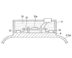
ハウジング2の上面には、図1に示すように、第一収納部2aの長手方向に沿って圧縮機基台4が設けられており、この圧縮機基台4上には、電気部品及び電子部品等の電装部品で構成されるインバータ制御装置10の制御機器類を収納してインバータ室を形成する筐体の保護ケース11が設けられている。
ここで、圧縮機基台4及び保護ケース11は、たとえばアルミニウムやアルミニウム基合金等のように熱伝導率が高く、しかも、軽量の材質によって構成されている。また、インバータ制御装置10は、保護ケース11内に収納設置されたCPU12a等の基板12及びパワー素子13等の電装部品を具備してなる制御機器類と、有底円筒形状とした第一収納部2aの底面部に密接して設けられたコンデンサ14とを具備して構成される。この場合、たとえば発熱量の大きいパワー素子13については、第一収納部2aの冷媒取入口3に近い位置に配置して吸入冷媒による効率のよい冷却を行うようにすればよい。さらに、冷却することが望ましいコンデンサ14についても、第一収納部2aの底面部に密接する配置としたので、吸入冷媒による冷却を行うことができる。
なお、当然ながら、インバータ制御部10の電装部品と保護ケース11及び圧縮機基台4とは絶縁されている。
As shown in FIG. 1, a
Here, the
Of course, the electrical components of the
インバータ制御装置10の制御機器類を収納設置する保護ケース11の内部には、電気的な接続等の作業が完了した後、内部空間を埋めるようにして絶縁ゲル剤15が充填される。この充填ゲル剤15は、保護ケース11の内部を完全に埋め尽くすように充填してもよいが、少なくとも電気部品や電子部品等の電装部品を完全に覆うような位置まで充填すればよい。具体例をあげると、基板12やパワー素子13等の電装部品が完全に絶縁ゲル剤15の中に埋設され、保護ケース10の内部に形成された上部空間に電装部品が露出して空気と接触するのを防止した位置まで充填すればよい。
ここで使用する絶縁ゲル剤15は、たとえば信越化学株式会社製の「KE1051J」または同等品が好適である。
The
As the insulating
このようにして保護ケース11内に絶縁ゲル剤15を充填すると、電装部品の絶縁がなされるのは勿論のこと、防湿や防振にも有効である。
最初に、防湿について説明すると、インバータ制御装置10と一体の電動圧縮機1が設置されるエンジンルーム内は温度変化が大きい環境であるため、高湿度状態で温度低下すると結露により水滴が発生する。このような結露水等の水滴は、電装部品を短絡させるなどトラブルの原因となる。しかし、電装部品が完全に絶縁ゲル剤15に覆われていると、水滴が電装部品まで到達しないよう防水されるので、保護ケース11内で短絡等の不具合が発生するのを防止できる。
When the insulating
First, the moisture prevention will be described. Since the engine room in which the electric compressor 1 integrated with the
次に、防振について説明する。インバータ制御部10が設置される環境は、車両の走行振動や車両を走行させる駆動源の振動に加えて、電動圧縮機1の振動が直接入力する。このため、基板12に振動が伝播してプリント配線等に亀裂を生じたり、あるいは、基板12等の電装部品を固定するビス等に緩みが生じることによる不具合の発生も懸念される。しかし、電装部品の周囲が絶縁ゲル剤15に覆われていると、外部から入力する振動を絶縁ゲル剤15が吸収して電装部品に作用する振動を低減し、あるいは、絶縁ゲル剤15が基板12等の大きな振動を抑制するので、基板12等の電装部品に亀裂の発生やビスの緩みなどが生じるようなことはない。
Next, image stabilization will be described. The environment in which the
上述したように、本発明の電動圧縮機1は、第一収納部2aとインバータ制御装置10との間で熱伝達が高効率で行われるので、低温ガス冷媒が流れて低温側となる第一収納部2aにパワー素子13等の発熱を効率的に逃がすことができる。従って、たとえば車両のエンジンルーム内等のような高温環境下に設置する場合にも、特別な冷却構造を用いることなしに、インバータ制御装置10を構成するパワー素子13やコンデンサ14等を低温ガス冷媒で冷却し、電装部品への熱による影響を低減することができるので、電動圧縮機1の信頼性や耐久性を低コストで向上させることができる。
As described above, in the electric compressor 1 according to the present invention, heat transfer is performed with high efficiency between the
また、保護ケース11内に収納設置された電装部品が絶縁ゲル剤15により覆われているので、保護ケース11内の電機部品は、電気的に絶縁されるとともに水滴の侵入が防止され、さらに、振動の影響を低減することもできるようになる。
従って、上述した本発明の電動圧縮機1は、エンジンルーム内のように高温、高湿及び高振動の設置環境に設置しても、絶縁ゲル剤15の充填や吸入冷媒を有効利用した冷却により、設置環境に起因する問題を解消して不具合の発生が防止されるので、信頼性や耐久性を向上させることできる。
なお、本発明は上述した実施形態に限定されるものではなく、本発明の要旨を逸脱しない範囲内において適宜変更することができる。
In addition, since the electrical component housed and installed in the
Therefore, even if the electric compressor 1 of the present invention described above is installed in an installation environment of high temperature, high humidity and high vibration as in an engine room, the insulating
In addition, this invention is not limited to embodiment mentioned above, In the range which does not deviate from the summary of this invention, it can change suitably.
1 車両用電動圧縮機
2 ハウジング
2a 第一収納部
2b 第二収納部
3 冷媒取入口
4 圧縮機基台
10 インバータ制御装置
11 保護ケース(筐体)
12 基板(電装部品)
13 パワー素子(電装部品)
14 コンデンサ
15 絶縁ゲル剤
DESCRIPTION OF SYMBOLS 1 Vehicle
12 Board (electric parts)
13 Power elements (electrical parts)
14
Claims (4)
前記電動機を制御する制御装置の制御機器類を収納設置する筐体内に、CPUやパワー素子等の発熱量の大きい電装部品の高さのみまで絶縁ゲル剤を充填したことを特徴とする車両用電動圧縮機。 In the vehicle electric compressor for driving the compression mechanism by the electric motor and compressing the refrigerant of the vehicle air conditioner,
An electric vehicle for vehicles characterized in that an insulating gel agent is filled only to the height of electrical components having a large calorific value, such as a CPU and a power element , in a housing that houses and installs control devices of a control device that controls the electric motor. Compressor.
前記電装部品はパワー素子を含み、
前記パワー素子は、前記冷媒取入口に近い位置に配置されていることを特徴とする請求項2に記載の車両用電動圧縮機。 The low-pressure refrigerant chamber is provided with a refrigerant inlet for taking in the refrigerant,
The electrical component includes a power element,
The vehicular electric compressor according to claim 2, wherein the power element is disposed at a position close to the refrigerant inlet.
Priority Applications (1)
| Application Number | Priority Date | Filing Date | Title |
|---|---|---|---|
| JP2005142370A JP4699085B2 (en) | 2005-05-16 | 2005-05-16 | Electric compressor for vehicles |
Applications Claiming Priority (1)
| Application Number | Priority Date | Filing Date | Title |
|---|---|---|---|
| JP2005142370A JP4699085B2 (en) | 2005-05-16 | 2005-05-16 | Electric compressor for vehicles |
Related Child Applications (1)
| Application Number | Title | Priority Date | Filing Date |
|---|---|---|---|
| JP2010161750A Division JP2010270760A (en) | 2010-07-16 | 2010-07-16 | Electric compressor for vehicle |
Publications (3)
| Publication Number | Publication Date |
|---|---|
| JP2006316754A JP2006316754A (en) | 2006-11-24 |
| JP2006316754A5 JP2006316754A5 (en) | 2009-08-27 |
| JP4699085B2 true JP4699085B2 (en) | 2011-06-08 |
Family
ID=37537637
Family Applications (1)
| Application Number | Title | Priority Date | Filing Date |
|---|---|---|---|
| JP2005142370A Expired - Fee Related JP4699085B2 (en) | 2005-05-16 | 2005-05-16 | Electric compressor for vehicles |
Country Status (1)
| Country | Link |
|---|---|
| JP (1) | JP4699085B2 (en) |
Families Citing this family (14)
| Publication number | Priority date | Publication date | Assignee | Title |
|---|---|---|---|---|
| JP4764395B2 (en) | 2007-09-21 | 2011-08-31 | 三菱重工業株式会社 | Inverter-integrated electric compressor |
| JP5285258B2 (en) * | 2007-09-28 | 2013-09-11 | 三菱重工業株式会社 | Electric compressor |
| JP2009257291A (en) * | 2008-04-21 | 2009-11-05 | Calsonic Kansei Corp | Electric compressor |
| JP5308722B2 (en) * | 2008-06-06 | 2013-10-09 | サンデン株式会社 | Electric compressor |
| JP5419406B2 (en) * | 2008-09-18 | 2014-02-19 | 三菱重工業株式会社 | Inverter device |
| JP5412098B2 (en) | 2008-12-05 | 2014-02-12 | 三菱重工業株式会社 | Inverter-integrated electric compressor and its inverter device |
| KR101069663B1 (en) | 2009-03-04 | 2011-10-05 | 주식회사 두원전자 | Electromotive compressor having inverter |
| JP5839769B2 (en) | 2009-03-06 | 2016-01-06 | 三菱重工業株式会社 | Inverter module and inverter-integrated electric compressor |
| JP2010285980A (en) | 2009-05-13 | 2010-12-24 | Sanden Corp | Inverter-integrated electric compressor |
| JPWO2012114426A1 (en) * | 2011-02-21 | 2014-07-07 | 株式会社日立製作所 | Vehicle air conditioning system |
| JP5697038B2 (en) | 2011-08-08 | 2015-04-08 | サンデン株式会社 | Electric circuit vibration-proof structure of electric compressor |
| JP5413435B2 (en) * | 2011-10-31 | 2014-02-12 | 株式会社豊田自動織機 | Electric compressor |
| CN102954648A (en) * | 2012-12-10 | 2013-03-06 | 合肥美的荣事达电冰箱有限公司 | Refrigeration equipment |
| JP2015014203A (en) | 2013-07-03 | 2015-01-22 | サンデン株式会社 | Electric circuit vibration resistance structure of electric compressor |
Citations (10)
| Publication number | Priority date | Publication date | Assignee | Title |
|---|---|---|---|---|
| JPS6221249A (en) * | 1985-07-22 | 1987-01-29 | Hitachi Ltd | Semiconductor device |
| JPH04162489A (en) * | 1990-10-24 | 1992-06-05 | Sanyo Electric Co Ltd | Hybrid integrated circuit |
| JPH05110268A (en) * | 1991-10-14 | 1993-04-30 | Mitsubishi Electric Corp | Sealed type mounted printed wiring board |
| JPH08116179A (en) * | 1994-10-18 | 1996-05-07 | Nippondenso Co Ltd | Container for electronic circuit |
| JP2002043470A (en) * | 2000-07-31 | 2002-02-08 | Aisin Aw Co Ltd | Electronic control unit |
| JP2003153552A (en) * | 2001-11-07 | 2003-05-23 | Matsushita Electric Ind Co Ltd | Arrangement structure and arrangement method for inverter, and compressor |
| JP2003222078A (en) * | 2002-01-30 | 2003-08-08 | Denso Corp | Motor compressor |
| JP2003262187A (en) * | 2002-03-07 | 2003-09-19 | Denso Corp | Electric compressor |
| JP2003282750A (en) * | 2002-03-20 | 2003-10-03 | Denso Corp | Electronic device and manufacturing method thereof |
| JP2004248362A (en) * | 2003-02-12 | 2004-09-02 | Hitachi Ltd | Inverter and refrigerator |
-
2005
- 2005-05-16 JP JP2005142370A patent/JP4699085B2/en not_active Expired - Fee Related
Patent Citations (10)
| Publication number | Priority date | Publication date | Assignee | Title |
|---|---|---|---|---|
| JPS6221249A (en) * | 1985-07-22 | 1987-01-29 | Hitachi Ltd | Semiconductor device |
| JPH04162489A (en) * | 1990-10-24 | 1992-06-05 | Sanyo Electric Co Ltd | Hybrid integrated circuit |
| JPH05110268A (en) * | 1991-10-14 | 1993-04-30 | Mitsubishi Electric Corp | Sealed type mounted printed wiring board |
| JPH08116179A (en) * | 1994-10-18 | 1996-05-07 | Nippondenso Co Ltd | Container for electronic circuit |
| JP2002043470A (en) * | 2000-07-31 | 2002-02-08 | Aisin Aw Co Ltd | Electronic control unit |
| JP2003153552A (en) * | 2001-11-07 | 2003-05-23 | Matsushita Electric Ind Co Ltd | Arrangement structure and arrangement method for inverter, and compressor |
| JP2003222078A (en) * | 2002-01-30 | 2003-08-08 | Denso Corp | Motor compressor |
| JP2003262187A (en) * | 2002-03-07 | 2003-09-19 | Denso Corp | Electric compressor |
| JP2003282750A (en) * | 2002-03-20 | 2003-10-03 | Denso Corp | Electronic device and manufacturing method thereof |
| JP2004248362A (en) * | 2003-02-12 | 2004-09-02 | Hitachi Ltd | Inverter and refrigerator |
Also Published As
| Publication number | Publication date |
|---|---|
| JP2006316754A (en) | 2006-11-24 |
Similar Documents
| Publication | Publication Date | Title |
|---|---|---|
| JP4699085B2 (en) | Electric compressor for vehicles | |
| JP2006316754A5 (en) | ||
| JP4718862B2 (en) | Electric compressor | |
| JP5687027B2 (en) | Inverter-integrated electric compressor | |
| JP5479139B2 (en) | Inverter-integrated electric compressor and assembly method thereof | |
| JP5517652B2 (en) | Inverter-integrated electric compressor and assembly method thereof | |
| JP5517650B2 (en) | Inverter-integrated electric compressor | |
| JP4719134B2 (en) | Inverter-integrated electric compressor | |
| JP4690769B2 (en) | Electric compressor for vehicles | |
| JP2008128142A5 (en) | ||
| JP4764395B2 (en) | Inverter-integrated electric compressor | |
| JP2010270760A (en) | Electric compressor for vehicle | |
| JP4884841B2 (en) | Inverter-integrated electric compressor | |
| JP2008175067A (en) | Electric compressor | |
| JP2008163767A (en) | Electric compressor | |
| JP2008163765A (en) | Electric compressor | |
| JP4436192B2 (en) | Control device for electric compressor | |
| JP2008180120A (en) | Motor driven compressor | |
| JP4830848B2 (en) | Electric compressor | |
| JP5686992B2 (en) | Inverter-integrated electric compressor | |
| JP4599222B2 (en) | Electric compressor for vehicles | |
| JP2008163764A (en) | Electric compressor | |
| JP2008175069A (en) | Electric compressor | |
| JP2008175068A (en) | Electric compressor | |
| JP2008157170A (en) | Motor-driven compressor |
Legal Events
| Date | Code | Title | Description |
|---|---|---|---|
| A621 | Written request for application examination |
Free format text: JAPANESE INTERMEDIATE CODE: A621 Effective date: 20080428 |
|
| A521 | Written amendment |
Free format text: JAPANESE INTERMEDIATE CODE: A523 Effective date: 20090710 |
|
| A977 | Report on retrieval |
Free format text: JAPANESE INTERMEDIATE CODE: A971007 Effective date: 20100118 |
|
| A131 | Notification of reasons for refusal |
Free format text: JAPANESE INTERMEDIATE CODE: A131 Effective date: 20100126 |
|
| A521 | Written amendment |
Free format text: JAPANESE INTERMEDIATE CODE: A523 Effective date: 20100329 |
|
| A131 | Notification of reasons for refusal |
Free format text: JAPANESE INTERMEDIATE CODE: A131 Effective date: 20100518 |
|
| A521 | Written amendment |
Free format text: JAPANESE INTERMEDIATE CODE: A523 Effective date: 20100716 |
|
| A131 | Notification of reasons for refusal |
Free format text: JAPANESE INTERMEDIATE CODE: A131 Effective date: 20100914 |
|
| A521 | Written amendment |
Free format text: JAPANESE INTERMEDIATE CODE: A523 Effective date: 20101110 |
|
| TRDD | Decision of grant or rejection written | ||
| A01 | Written decision to grant a patent or to grant a registration (utility model) |
Free format text: JAPANESE INTERMEDIATE CODE: A01 Effective date: 20110208 |
|
| A61 | First payment of annual fees (during grant procedure) |
Free format text: JAPANESE INTERMEDIATE CODE: A61 Effective date: 20110302 |
|
| R151 | Written notification of patent or utility model registration |
Ref document number: 4699085 Country of ref document: JP Free format text: JAPANESE INTERMEDIATE CODE: R151 |
|
| LAPS | Cancellation because of no payment of annual fees |