JP4695457B2 - System and method for collecting and distributing party identification data - Google Patents
System and method for collecting and distributing party identification data Download PDFInfo
- Publication number
- JP4695457B2 JP4695457B2 JP2005236901A JP2005236901A JP4695457B2 JP 4695457 B2 JP4695457 B2 JP 4695457B2 JP 2005236901 A JP2005236901 A JP 2005236901A JP 2005236901 A JP2005236901 A JP 2005236901A JP 4695457 B2 JP4695457 B2 JP 4695457B2
- Authority
- JP
- Japan
- Prior art keywords
- identification data
- network
- transmission event
- network transmission
- participant
- Prior art date
- Legal status (The legal status is an assumption and is not a legal conclusion. Google has not performed a legal analysis and makes no representation as to the accuracy of the status listed.)
- Active
Links
- 238000000034 method Methods 0.000 title claims description 18
- 230000005540 biological transmission Effects 0.000 claims description 82
- 238000012544 monitoring process Methods 0.000 claims description 19
- 230000015654 memory Effects 0.000 claims description 16
- 230000011664 signaling Effects 0.000 claims description 13
- 230000008054 signal transmission Effects 0.000 claims description 12
- 238000012546 transfer Methods 0.000 claims description 11
- 230000006870 function Effects 0.000 claims description 6
- 230000000977 initiatory effect Effects 0.000 claims description 3
- 238000012545 processing Methods 0.000 claims description 3
- 230000007781 signaling event Effects 0.000 claims description 2
- 238000004891 communication Methods 0.000 description 13
- 238000010586 diagram Methods 0.000 description 8
- 238000005516 engineering process Methods 0.000 description 7
- 238000012360 testing method Methods 0.000 description 6
- 238000004590 computer program Methods 0.000 description 5
- 238000012806 monitoring device Methods 0.000 description 4
- 230000004044 response Effects 0.000 description 2
- 230000003831 deregulation Effects 0.000 description 1
- 239000000284 extract Substances 0.000 description 1
- 230000007246 mechanism Effects 0.000 description 1
- 230000003287 optical effect Effects 0.000 description 1
- 230000001360 synchronised effect Effects 0.000 description 1
Images


Classifications
-
- H—ELECTRICITY
- H04—ELECTRIC COMMUNICATION TECHNIQUE
- H04L—TRANSMISSION OF DIGITAL INFORMATION, e.g. TELEGRAPHIC COMMUNICATION
- H04L43/00—Arrangements for monitoring or testing data switching networks
-
- H—ELECTRICITY
- H04—ELECTRIC COMMUNICATION TECHNIQUE
- H04L—TRANSMISSION OF DIGITAL INFORMATION, e.g. TELEGRAPHIC COMMUNICATION
- H04L65/00—Network arrangements, protocols or services for supporting real-time applications in data packet communication
- H04L65/1066—Session management
- H04L65/1101—Session protocols
- H04L65/1104—Session initiation protocol [SIP]
-
- H—ELECTRICITY
- H04—ELECTRIC COMMUNICATION TECHNIQUE
- H04L—TRANSMISSION OF DIGITAL INFORMATION, e.g. TELEGRAPHIC COMMUNICATION
- H04L65/00—Network arrangements, protocols or services for supporting real-time applications in data packet communication
- H04L65/80—Responding to QoS
-
- H—ELECTRICITY
- H04—ELECTRIC COMMUNICATION TECHNIQUE
- H04M—TELEPHONIC COMMUNICATION
- H04M7/00—Arrangements for interconnection between switching centres
- H04M7/006—Networks other than PSTN/ISDN providing telephone service, e.g. Voice over Internet Protocol (VoIP), including next generation networks with a packet-switched transport layer
- H04M7/0081—Network operation, administration, maintenance, or provisioning
- H04M7/0084—Network monitoring; Error detection; Error recovery; Network testing
-
- H—ELECTRICITY
- H04—ELECTRIC COMMUNICATION TECHNIQUE
- H04Q—SELECTING
- H04Q3/00—Selecting arrangements
- H04Q3/0016—Arrangements providing connection between exchanges
-
- H—ELECTRICITY
- H04—ELECTRIC COMMUNICATION TECHNIQUE
- H04L—TRANSMISSION OF DIGITAL INFORMATION, e.g. TELEGRAPHIC COMMUNICATION
- H04L43/00—Arrangements for monitoring or testing data switching networks
- H04L43/10—Active monitoring, e.g. heartbeat, ping or trace-route
- H04L43/106—Active monitoring, e.g. heartbeat, ping or trace-route using time related information in packets, e.g. by adding timestamps
-
- H—ELECTRICITY
- H04—ELECTRIC COMMUNICATION TECHNIQUE
- H04L—TRANSMISSION OF DIGITAL INFORMATION, e.g. TELEGRAPHIC COMMUNICATION
- H04L43/00—Arrangements for monitoring or testing data switching networks
- H04L43/18—Protocol analysers
-
- H—ELECTRICITY
- H04—ELECTRIC COMMUNICATION TECHNIQUE
- H04M—TELEPHONIC COMMUNICATION
- H04M1/00—Substation equipment, e.g. for use by subscribers
- H04M1/253—Telephone sets using digital voice transmission
- H04M1/2535—Telephone sets using digital voice transmission adapted for voice communication over an Internet Protocol [IP] network
Description
本発明は、一般にネットワーク伝送のモニタに関する。 The present invention relates generally to network transmission monitoring.
ネットワーク位置から関係者(participant)識別データを収集し、ネットワーク位置に関係者識別データを分配する必要性については、下記の特定の応用例に言及することにより、最も明確な解説が可能になる。 The need for collecting participant identification data from the network location and distributing the participant identification data to the network location is most clearly explained by referring to the specific application below.
世界的規模の規制撤廃及びパケット交換テクノロジによって、電気通信産業に劇的な変化がもたらされた。現在では、インターネットのようなパケット交換ネットワークを介した音声通信が求められている。今や、公衆交換電話網(PSTN)及びインターネットを統合したインターネット・テクノロジによる音声通信が利用可能である。インターネット・テクノロジによる音声通信は、ボイス・オーバ・インターネット・プロトコル(VoIP)とも呼ばれる。ボイス・オーバIP(VoIP)では、インターネット・プロトコル(IP)を利用し、インターネット・プロトコルを利用するネットワークを介して、音声をパケットとして伝送する。従って、VoIPは、インターネット、イントラネット、及び、ローカル・エリア・ネットワーク(LAN)のような、インターネット・プロトコルを利用する任意のデータ・ネットワークにおいて実現可能である。 Global deregulation and packet-switching technology have led to dramatic changes in the telecommunications industry. Currently, there is a demand for voice communication via a packet switching network such as the Internet. Voice communication is now available using Internet technology that integrates the public switched telephone network (PSTN) and the Internet. Voice communication by Internet technology is also called Voice over Internet Protocol (VoIP). Voice over IP (VoIP) uses Internet Protocol (IP) and transmits voice as a packet through a network using Internet Protocol. Thus, VoIP can be implemented in any data network that utilizes Internet protocols, such as the Internet, intranets, and local area networks (LANs).
大部分のVoIPにおいて、VoIPには、2つの独立したゲートウェイ、すなわち、信号ゲートウェイと媒体ゲートウェイが含まれている。VoIP通話において、電話番号をダイヤルすると、信号プロトコルを利用して、その電話番号がIPホストにマッピングされる。次に、信号プロトコルを利用して、媒体セッション(音声、ビデオ等)が設定される。これらのプロトコルには、電話番号情報が含まれている。媒体セッションの設定が済むと、VoIPデータ通信は、リアルタイム転送プロトコル/ユーザ・データグラム・プロトコル/インターネット・プロトコル(RTP/UDP/IP)をプロトコル・スタックとして利用する。 In most VoIP, VoIP includes two independent gateways: a signaling gateway and a media gateway. When a telephone number is dialed in a VoIP call, the telephone number is mapped to an IP host using a signaling protocol. Next, a media session (voice, video, etc.) is set up using a signaling protocol. These protocols include telephone number information. Once the media session is set up, VoIP data communication uses Real-time Transfer Protocol / User Datagram Protocol / Internet Protocol (RTP / UDP / IP) as a protocol stack.
信号及び媒体情報は、ネットワークの異なるセグメントを通って伝わる可能性があるので、RTP媒体伝送をモニタしても、RTP媒体伝送の発信側または受信側の電話番号が確実に得られるわけではない。 Since signal and media information can travel through different segments of the network, monitoring the RTP media transmission does not ensure that the telephone number of the originating or receiving side of the RTP media transmission is obtained.
従って、本発明の目的は、RTP(ネットワーク)伝送事象に電話番号(関係者識別データ)を割り当てるための手段を提供することにある。 Accordingly, it is an object of the present invention to provide a means for assigning telephone numbers (party identification data) to RTP (network) transmission events.
本発明の上述の目的、並びに、本発明のさらなる及び他の目的及び利点については、後述する本発明の実施態様によって実現される。 The above objects of the present invention, as well as further and other objects and advantages of the present invention, are realized by the embodiments of the present invention described below.
関係者識別データをネットワーク伝送事象に割り当てるための方法及びシステムが開示される。 A method and system for assigning participant identification data to a network transmission event is disclosed.
本発明の方法には、ほぼある関係者位置におけるネットワーク伝送事象をモニタするステップと、ほぼその関係者位置において、関係者識別データ及びネットワーク伝送事象に関する識別データを得るステップが含まれている。次に、関係者識別データ及びネットワーク伝送事象に関する識別データは、所定の(中央とも称される)モニタ位置に供給され、データベースに記憶される。特定の関係者識別データを照会するため、別のネットワーク伝送事象に関連した識別データが、ネットワークにおける別の位置から中央モニタ位置に供給される。照会の結果、特定の関係者識別データが得られると、特定の関係者識別データは、中央モニタ位置から別のネットワーク位置に供給される。 The method of the present invention includes the steps of monitoring network transmission events at approximately a participant location, and obtaining participant identification data and identification data relating to the network transmission event at approximately the participant location. The participant identification data and the identification data regarding the network transmission event are then supplied to a predetermined (also called central) monitor location and stored in a database. To query for specific party identification data, identification data associated with another network transmission event is provided from another location in the network to the central monitor location. As a result of the query, specific participant identification data is obtained, and the specific participant identification data is provided from the central monitor location to another network location.
これにより、特定の関係者識別データが、別のネットワーク伝送事象に割り当てられる。 This assigns specific party identification data to another network transmission event.
実施態様の1つでは、特定の識別データが信号伝送事象から得られる。 In one embodiment, specific identification data is obtained from the signal transmission event.
これらの方法を実施するシステム、及び、この方法を実行するコンピュータ可読コードが納められた、コンピュータ・プログラムについても開示される。 Also disclosed is a system for performing these methods and a computer program containing computer readable code for performing the methods.
本発明、並びに、本発明の他の及びさらなる目的のより明確な理解が得られるように、添付の図面および発明の詳細な説明が参照され、発明の範囲については、特許請求の範囲において指摘される。 For a clearer understanding of the present invention and other and further objects of the invention, reference is made to the accompanying drawings and detailed description of the invention, the scope of which is pointed out in the appended claims. The
以下では、ネットワーク伝送事象に関係者識別データを割り当てるための方法及びシステムについて開示される。 In the following, a method and system for assigning participant identification data to a network transmission event is disclosed.
図1には、本発明の方法の実施態様10を表わした流れ図が示されている。図1を参照すると、ほぼある関係者位置において、ネットワーク伝送事象がモニタされ(図1のステップ20)、関係者識別データ及びネットワーク伝送事象に関連した識別データが取得される(図1のステップ30)。関係者識別データ及びネットワーク伝送事象に関連した識別データは、次に、所定の(中央とも称される)モニタ位置に供給され(図1のステップ40)、中央モニタ位置のデータベースに記憶される(図1のステップ50)。(本明細書において用いられる限りにおいて、データベースは、容易にアクセスし、管理し、更新することができるように構成された任意の情報集合である。)別のネットワーク伝送事象に関連した識別データが、ネットワークの別の位置から中央モニタ位置に供給されるが(図1のステップ60)、別のネットワーク伝送事象に関連した識別データは、ネットワークの別の位置で得られ、当該別のネットワーク伝送事象に関連した当該識別データに対応する特定の関係者識別データについて、データベースへの照会が行われる(図1のステップ70)。照会の結果、当該特定の関係者識別データが得られると、特定の関係者識別データは、中央モニタ位置から、ほぼネットワークの別の位置に配置されたネットワーク・モニタ装置に供給される(図1のステップ80)。当該特定の関係者識別データは、これにより、別のネットワーク伝送事象に割り当てられる。
FIG. 1 shows a flow diagram representing an
実施態様の1つにおいて、図1のステップ30では、関係者識別データが信号伝送事象から得られる。実施態様によっては、次に、別のネットワーク伝送事象に関連した識別データが、リアルタイム転送事象から得られるものもある。実施態様によっては、信号伝送事象がインターネット・プロトコルを利用した伝送である場合、信号伝送事象において、制限するわけではないが、H.323、SIP、MGCP、または、Megaco/H.248のような信号プロトコルが利用されるものもある。
In one embodiment, at
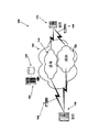
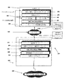
図2には、本発明のシステムの実施態様100を表わした図が示されており、図3には、本発明のシステムの実施態様200を表わしたもう1つの概略図が示されている。図2及び図3を参照すると、図2に示す本発明のシステムの実施態様100には、ほぼ関係者位置130において生じるネットワーク伝送事象のモニタが可能なネットワーク・モニタ・サブシステム140、中央モニタ・サブシステム(サーバ)150、及び、別のネットワーク位置170における別のネットワーク・モニタ装置160が含まれている。実施態様の1つでは、ネットワーク・モニタ・サブシステム140、160と、中央モニタ・サブシステム(サーバ)150は、両方とも、制限するわけではないが、サブシステムに、ネットワーク・インターフェイス・コンポーネント320、1つ以上のプロセッサ310、1つ以上のコンピュータ可読メモリ360、及び、少なくとも1つの他のコンピュータ可読メモリ340が含まれている、図4に示すような実施例をベースにしている。ネットワーク・インターフェイス・コンポーネント320、1つ以上のプロセッサ310、1つ以上のコンピュータ可読メモリ360、及び、少なくとも1つの他のコンピュータ可読メモリ340は、相互接続手段325(制限するわけではないが、共通「バス」のような)によって動作可能に接続されている。
FIG. 2 shows a diagram representing an
図2に示す実施態様の場合、中央モニタ・サブシステム(サーバ)150とのネットワーク伝送及び通信は、ネットワーク105を介して行われるが、信号伝送事象は、ネットワークのセグメントの1つで伝わり、媒体伝送事象は、異なるセグメントで伝わる。図2において、2つのセグメントは、2つのサブネットワーク110、120として示されている。
In the embodiment shown in FIG. 2, network transmission and communication with the central monitoring subsystem (server) 150 occurs over the
図3に示す概略図は、(プロトコルを表わすのに用いられるものと同様の)階層表現を利用して、本発明のシステムの実施態様200を表わしたものである。図3を参照すると、ネットワーク・モニタ・サブシステム140は、収集ハードウェア215(収集ハードウェアは、制限するわけではないが、アジレント・テクノロジ社の「J6800Aネットワーク・アナライザ」のようなネットワーク・アナライザにおいて見受けられるものと同様とすることが可能である)によって、ほぼ図2に示す関係者位置130で生じるネットワーク伝送事象からデータを収集する。データは、試験機器アプリケーション・コード220によって解析される。試験機器アプリケーション・コード220によって、ほぼ関係者位置130において、関係者識別データ及びネットワーク伝送事象に関連した識別データを取得するための手段が得られる。実施態様の1つでは、信号メッセージには、関係者識別データ及びネットワーク伝送事象に関連した識別データが含まれている。試験機器アプリケーション・コード220によって、信号メッセージから関係者識別データ及びネットワーク伝送事象に関連した識別データが抽出される。図3に示す実施態様の場合、プロセッサ310及びネットワーク・インターフェイス320と共に、中央モニタ・サブシステム150との通信に用いられるソフトウェア(例えば、XML API225、通信サーブレット230、及び、HTTPサーバ235によって、図示実施態様のソフトウェア(コード)が得られる)が、中央モニタ・サブシステム150に関係者識別データ及びネットワーク伝送事象に関連した識別データを提供するための手段を構成する。
The schematic shown in FIG. 3 represents an
中央モニタ・サブシステム150では、通信に用いられるソフトウェア(図示実施態様の場合、HTTP層255、XML API260のような)、及び、データ収集ソフトウェア262及びデータ記憶ソフトウェア265によって、関係者識別データ及びネットワーク伝送事象に関連した識別データが受信され、記憶される。関係者識別データ及びネットワーク伝送事象に関連した識別データは、データベース155に記憶される。データベース155は、データベースに常駐する情報を含むデータ構造が記憶されている、図4のメモリ340のような、1つ以上のコンピュータ可読メモリに配置されている。データ構造には、1つ以上のコンピュータ可読メモリに記憶された1つ以上のデータ・オブジェクト対が含まれており、1つ以上のデータ・オブジェクト対には、所定の関係者識別データ・オブジェクト、及び、ネットワーク伝送事象に関連した識別データ・オブジェクトが含まれている。
In
別のネットワーク位置170において、別のネットワーク伝送事象が、収集ハードウェア215及び試験機器アプリケーション・コード(ソフトウェア)220によってモニタされる。データは、試験機器アプリケーション・コード220によって解析される。試験機器アプリケーション・コード220によれば、別のネットワーク伝送事象に関連した識別データを取得するための手段が得られる。図3に示す実施態様の場合、プロセッサ310及びネットワーク・インターフェイス320と共に、中央モニタ・サブシステム150との通信に用いられるソフトウェア(XML API225、通信サーブレット230、及び、HTTPサーバ235によって、図示実施態様のソフトウェア(コード)が得られる)が、中央モニタ・サブシステム150に別のネットワーク伝送事象に関連した識別データを提供するための手段を構成する。
At another
中央モニタ・サブシステム150では、図4のメモリ360のような、1つ以上のコンピュータ可使メモリに納められたコンピュータ可読コード(ソフトウェア)によって、中央モニタ・サブシステム150の1つ以上のプロセッサに、別のネットワーク伝送事象に関連した識別データに対応する特定の関係者識別データについて、データベース155への照会を実施させる。照会の結果、特定の関係者識別データが得られる場合には、通信に用いられるソフトウェア(図示実施態様の場合、HTTP層255、XML API 260)、データ検索用ソフトウェアが、中央モニタ・サブシステム150における1つ以上のプロセッサ及びネットワーク・インターフェイス(図4のプロセッサ310及びネットワーク・インターフェイス320のような)と共に、別のネットワーク・モニタ・サブシステム160に特定の関係者識別データを供給するための手段を構成する。
In
ネットワーク・モニタ装置140、160のそれぞれにおける、及び、中央モニタ・サブシステム150における、図4の1つ以上のコンピュータ可読メモリ360のような1つ以上のコンピュータ可読メモリには、コンピュータ可読コードが納められており、コンピュータ可読コードによって、ネットワーク・モニタ装置のそれぞれ及び中央モニタ・サブシステム150における少なくとも1つのプロセッサに、ほぼ関係者位置におけるネットワーク伝送事象をモニタさせ、ほぼ関係者位置130において、関係者識別データ及びネットワーク伝送事象に関連した識別データを取得させ、関係者識別データ及びネットワーク伝送事象に関連した識別データを中央モニタ位置(サブシステム)150に供給させ、関係者識別データ及びネットワーク伝送事象に関連した識別データを中央モニタ位置(サブシステム)150のデータベース155に記憶させ、ネットワークの別の位置170から中央モニタ位置(サブシステム)150に、ネットワークの別の位置で取得した別のネットワーク伝送事象に関連した識別データを供給させ、別のネットワーク伝送事象に関連した識別データに対応する特定の関係者識別データについて、データベース155への照会を実施させ、照会の結果、特定の関係者識別データが得られると、中央モニタ位置150から別のネットワーク・モニタ装置160に、その特定の関係者識別データを供給させることが可能になる。
One or more computer readable memories, such as one or more computer
本発明のさらに明確な理解が得られるように、下記の例証となる実施態様について言及する。もう一度図2を参照すると、起呼側電話130(すなわち、送信元)は、ネットワーク105を介した受信側電話170(すなわち、受信先)との通話を開始する。実施態様の1つでは、通話は、信号プロトコルとしてSIPを利用した信号メッセージ(信号伝送事象)によって開始される。
In order that a more clear understanding of the invention may be obtained, reference is made to the following illustrative embodiments. Referring once again to FIG. 2, the calling phone 130 (ie, the source) initiates a call with the receiving phone 170 (ie, the destination) over the
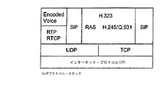
SIPプロトコルは、TCP/IP(転送制御プロトコル/インターネット・プロトコル)スタックにおける転送層より上位で機能する、テキスト・ベースのプロトコルである。(SIPは、参考までに本明細書において援用されている、<URL:http://www.ietf.org/rfc/rfc3261.txt>で入手可能な、RFC3261、「SIP:Session Initiation Protocol」、2002年6月において定義されている。)SIPは、その転送プロトコルとして、TCP(転送制御プロトコル)及びUDP(ユーザ・データグラム・プロトコル)を含む任意の転送プロトコルを利用することが可能である。図5には、信号プロトコルとして、SIPとH.323の両方のためのプロトコル・スタックが示されている。 The SIP protocol is a text-based protocol that functions above the transport layer in the TCP / IP (Transfer Control Protocol / Internet Protocol) stack. (SIP is RFC 3261, “SIP: Session Initiation Protocol”, available at <URL: http: //www.ietf.org/rfc/rfc3261.txt>, incorporated herein by reference. SIP is defined in June 2002.) SIP can use any transfer protocol including TCP (Transfer Control Protocol) and UDP (User Datagram Protocol) as its transfer protocol. FIG. 5 shows SIP and H.264 as signal protocols. Protocol stacks for both H.323 are shown.
SIPを利用して、信号情報を伝達することが可能であるが、セッション記述情報は、セッション記述プロトコル(SDP)のような別のプロトコルによって伝達される。SDPは純粋にセッション記述用のフォーマットである。SDPには転送プロトコルが組み込まれない。(SDPは、参考までに本明細書において援用されている、<URL:http://www.ietf.org/rfc/rfc2327.txt>で入手可能な、RFC2327、「SDP:Session Description Protocol」、1998年4月において定義されている。)転送プロトコルへのアクセスは、SIPのようなプロトコルと共に、SDPを利用することによって可能になる。 Although it is possible to convey signaling information using SIP, the session description information is conveyed by another protocol such as the Session Description Protocol (SDP). SDP is purely a session description format. SDP does not incorporate a transfer protocol. (SDP is RFC 2327, “SDP: Session Description Protocol”, available at <URL: http: //www.ietf.org/rfc/rfc2327.txt>, incorporated herein by reference. Defined in April 1998.) Access to transport protocols is made possible by using SDP along with protocols such as SIP.
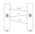
通話(セッション)を開始するステップは、図6に示すようにかなり単純である。(1)送信元が受信先にINVITE要求を送る。INVITEメッセージが受信先に到達すると、(2)受信先はOKメッセージで応答する。送信元が、受信先がINVITEを受信したことを表わすOKメッセージを受信すると、(3)送信元はACKメッセージを送り、これが受信されると、セッションが開始されることになる。実施態様によっては、プロキシ・サーバ(不図示)を利用して、送信元及び受信先からメッセージを受信し、メッセージを転送するものもある。 The step of initiating a call (session) is fairly simple as shown in FIG. (1) The transmission source sends an INVITE request to the reception destination. When the INVITE message reaches the receiver, (2) the receiver responds with an OK message. When the transmission source receives an OK message indicating that the reception destination has received INVITE, (3) the transmission source sends an ACK message, and when this is received, the session is started. In some embodiments, a proxy server (not shown) is used to receive a message from a source and a destination and forward the message.
この例示の実施態様において、下記は、INVITE SIPメッセージの内容の一例である。(この例の場合、送信元はアリスで、受信先はボブである。)アリスからのINVITE SIPメッセージには、下記が含まれている。 In this exemplary embodiment, the following is an example of the contents of an INVITE SIP message. (In this example, the source is Alice and the destination is Bob.) The INVITE SIP message from Alice contains:
INVITE sip:bo@agi.com SIP/3.0
Via:SIP/3.0/UDP 192.2.4.4:5060
From:Alice<sip:111−1234@agi.com>
To:Bob<sip:111−6666@agi.com>
tag=203 941 885
Call−ID:123456789@192.2.4.4
CSeq:1 INVITE
Contact:<sip:111−1234@agi.com>
Content−Type:application/SDP
Content−Length:182
v=0
o=Alice. . .IP4 192.2.4.4
・
m=audio 5060 RTP ...
第1行は、そのメッセージがINVITEメッセージであることを表わしている。「Via」には、IPアドレス、ポート番号、及び、アリスがボブの応答において利用されることを望む転送プロトコルが含まれている。「To」行には、ボブの名前及び電話番号が含まれている。「From」行には、アリスの名前及び電話番号が含まれている。Call−IDには、その呼び出しの一意性識別子が含まれている。Content Typeにはメッセージ内容が記述され、Content Lengthには、メッセージ本体の長さが記述されている。空白行は、SIPヘッダの終了を示しており、SDPセッション記述情報の先頭「v」は、SDPのバージョンを識別し、「o」は、オーナ/クリエータを識別し、セッション識別子「p」は、電話番号を提示し、「m」は、媒体記述、すなわち、そのタイプ、ポート、及び、送信元が進んで受信及び送信しようとする可能性のあるフォーマットを提示している。
INVITE sip: bo @ agi. com SIP / 3.0
Via: SIP / 3.0 / UDP 192.2.2.4:5060
From: Alice <sip: 111-1234 @ agi. com>
To: Bob <sip: 111-6666 @ agi. com>
tag = 203 941 885
Call-ID: 123456789@192.2.4.4
CSeq: 1 INVITE
Contact: <sip: 111-1234 @ agi. com>
Content-Type: application / SDP
Content-Length: 182
v = 0
o = Alice. . . IP4 192.2.2.4
・
m = audio 5060 RTP. . .
The first line indicates that the message is an INVITE message. “Via” includes the IP address, port number, and transfer protocol that Alice wants to be utilized in Bob's response. The “To” line contains Bob's name and phone number. The “From” line contains Alice's name and phone number. The Call-ID includes a unique identifier for the call. The content of the message is described in the Content Type, and the length of the message body is described in the Content Length. The blank line indicates the end of the SIP header, the top “v” of the SDP session description information identifies the SDP version, “o” identifies the owner / creator, and the session identifier “p” Present the phone number, and “m” presents the media description, ie its type, port, and format that the sender may be willing to receive and transmit.
ボブからの応答であるOKメッセージには、下記が含まれている。 The OK message, which is a response from Bob, includes the following.
SIP/3.0 200 OK
Via:SIP/3.0/UDP 192.2.4.4:5060
From:Alice<sip:111−1234@agi.com>
To:Bob<sip:111−6666@agi.com>
tag=203 941 885
Call−ID:123456789@192.2.4.4
CSeq:1 INVITE
Contact:<sip:111−1234@agi.com>
Content−Type:application/SDP
Content−Length:198
v=0
o=Bob. . . IN IP4 192.1.2.3
p=1 111 111 6666
m=audio 5004 RTP
もう一度図2を参照すると、ネットワーク・モニタ・サブシステム140は、送信元位置130における信号伝送をモニタする。INVITE及びOKメッセージと、対応するセッション記述を構文解析することにより、ネットワーク・モニタ・サブシステム140は、送信元及び受信先(アリス及びボブ)に関する送信元及び受信先電話番号、ネットワーク・アドレス、及び、ポート番号を得ることができる。送信元及び受信先に関する送信元及び受信先電話番号、ネットワーク・アドレス、及び、ポート番号は、次に、中央モニタ・サーバ150に供給され、データベース155に記憶される。実施態様の1つでは、ネットワーク・モニタ・サブシステム140は、制限するわけではないが、アジレント・テクノロジ社製の「J6800Aネットワーク・アナライザ(ハードウェア)及びJ6844A電話ネットワーク・アナライザ(ソフトウェア)」のようなネットワーク・アナライザである。
SIP / 3.0 200 OK
Via: SIP / 3.0 / UDP 192.2.2.4:5060
From: Alice <sip: 111-1234 @ agi. com>
To: Bob <sip: 111-6666 @ agi. com>
tag = 203 941 885
Call-ID: 123456789@192.2.4.4
CSeq: 1 INVITE
Contact: <sip: 111-1234 @ agi. com>
Content-Type: application / SDP
Content-Length: 198
v = 0
o = Bob. . . IN IP4 191.2.2.3
p = 1 111 111 6666
m = audio 5004 RTP
Referring once again to FIG. 2, the
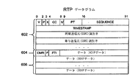
信号メッセージで指定されているように、この音声(VoIP)データ通信では、リアルタイム転送プロトコル/ユーザ・データグラム・プロトコル/インターネット・プロトコル(RTP/UDP/IP)がプロトコル・スタックとして利用される。図7には、RTPデータグラムの一例が示されている。RTPフィールドには、シーケンス番号、タイムスタンプ、同期送信元識別子、及び、寄与送信元識別子が含まれている。(RTPは、参考までに本明細書において援用されている、<URL:http://www.ietf.org/rfc/rfc3550.txt>で入手可能な、RFC3550、「RTP:A Transport Protocol for Real−time applications」、2003年7月において定義されている。)
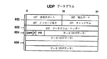
送信元及び受信先に関して、RTPセッションは、特定の対をなす宛先転送アドレス(1つのネットワーク・アドレスにRTP及びRTCPに関するポート対を加えたもの)によって定義される。図8には、ポート情報を例示したUDPデータグラムが示されている。RTPデータ転送プロトコルは、制御プロトコル(RTCP)によって、データ配信のモニタを可能にし(マルチキャスト通信へのスケーラビリティを与え)、何らかの制御及び識別機能を与えるように拡張される。図9には、送信側報告RTCPデータグラムが示されている。
As specified in the signaling message, this voice (VoIP) data communication utilizes a real-time transfer protocol / user datagram protocol / Internet protocol (RTP / UDP / IP) as a protocol stack. FIG. 7 shows an example of an RTP datagram. The RTP field includes a sequence number, a time stamp, a synchronous transmission source identifier, and a contributing transmission source identifier. (RTP is RFC 3550, “RTP: A Transport Protocol for Real, available at <URL: http: //www.ietf.org/rfc/rfc3550.txt>, incorporated herein by reference.” -Time applications ", defined in July 2003.)
With respect to source and destination, an RTP session is defined by a specific pair of destination forwarding addresses (one network address plus a port pair for RTP and RTCP). FIG. 8 shows a UDP datagram illustrating port information. The RTP data transfer protocol is extended by the control protocol (RTCP) to allow monitoring of data delivery (giving scalability to multicast communications) and to provide some control and identification capabilities. FIG. 9 shows a sender report RTCP datagram.
もう一度図2を参照すると、他のネットワーク・モニタ・サブシステム160が、受信先位置170において、起呼側電話130(すなわち、送信元)から受信側電話170(すなわち、受信先)への通話(phone call)(ネットワーク伝送事象)によって生じるRTPデータ・パケットをモニタする。実施態様の1つでは、他のネットワーク・モニタ・サブシステム160は、制限するわけではないが、アジレント・テクノロジ社製の「J6800Aネットワーク・アナライザ(ハードウェア)及びJ6844A電話ネットワーク・アナライザ(ソフトウェア)」のようなネットワーク・アナライザである。他のネットワーク・モニタ・サブシステム160は、RTP(またはRTPC)パケットから、RTPセッションを定義する、対をなす宛先転送アドレス(1つのネットワーク・アドレスにRTP及びRTCPに関するポート対を加えたもの)を得ることができる。RTP伝送に関する識別データは、受信先170の位置から中央モニタ・サーバ(位置)150に供給される。ネットワーク・アドレス及びRTP伝送事象に関連したポート・データに対応する特定の電話番号データについて、データベース155への照会が行われる。照会の結果、特定の電話番号データが得られると、特定の電話番号データは、中央モニタ位置150から、他のネットワーク・モニタ装置160に供給される。特定の電話番号データは、これにより、RTP伝送事象に割り当てられる。
Referring once again to FIG. 2, another
先行例において、ネットワーク・モニタ・サブシステム140は、送信元及び受信先電話番号、送信元及び受信先に関するネットワーク・アドレス、及び、ポート番号を中央モニタ・サーバ150(位置)に供給するが、関係者識別データ及び信号伝送事象に関連した識別データを中央モニタ・サーバに供給するネットワーク・モニタ・サブシステムの位置は、本発明の制限事項ではない。本発明の別の実施態様では、2つのネットワーク・モニタ・サブシステムの役割を交換することが可能である。
In the preceding example, the
上述の例では、SIPが信号プロトコルとして利用されているが、留意すべきは、制限するわけではないが、H.323、MGCP、または、Megaco/H.248といった他の信号プロトコルを利用して、本発明を実施することも可能であるという点である。 In the above example, SIP is used as the signaling protocol. H.323, MGCP, or Megaco / H. It is also possible to implement the present invention using other signal protocols such as H.248.
ある制御プロトコルから、送信元及び受信先電話番号、送信元及び受信先に関するネットワーク・アドレス、及び、ポート番号を得ることができる場合、そのプロトコルを利用して、本発明を実施することが可能である。 If the source and destination telephone numbers, the network addresses and the port numbers for the source and destination can be obtained from a certain control protocol, the present invention can be implemented using that protocol. is there.
やはり留意しておくべきは、中央モニタ位置(サーバ)は、ハードウェア、ソフトウェア、または、それらの組み合わせによって実施可能であるという点である。中央モニタ位置(サーバ)の典型的な実施態様には、ソフトウェア・ベースのシステムである、アジレント・テクノロジ社製のJ6782Aネットワーク・トラブルシューティング・センタ(NTC)がある。やはり留意すべきは、本発明はその実施態様に制限されるものではないという点である。 It should also be noted that the central monitor location (server) can be implemented by hardware, software, or a combination thereof. A typical implementation of a central monitor location (server) is the J6782A Network Troubleshooting Center (NTC) manufactured by Agilent Technologies, a software-based system. It should also be noted that the present invention is not limited to that embodiment.
さらに、典型的なネットワーク105、信号ネットワーク110、及び、媒体ネットワーク120は、それぞれ、説明を容易にするため、単純化されている。ネットワーク105、110、120には、ネットワーク、通信リンク、プロキシ、ファイアウォール、または、他のセキュリティ機構、インターネット・サービス・プロバイダ(ISP)、MCU、ゲートキーパ、ゲートウェイ、及び、他の要素といった、より多くのまたはより少ない追加要素を含むことが可能である。
Further, the
一般に、上述の技法は、例えば、ハードウェア、ソフトウェア、ファームウェア、または、それらの任意の組み合わせによって実施可能である。上述の技法は、プロセッサを含むプログラマブル・コンピュータで実行される1つ以上のコンピュータ・プログラム、プロセッサによる読み取りが可能な記憶媒体(例えば、揮発性及び不揮発性メモリ、及び/または、記憶素子を含む)、少なくとも1つの入力装置、及び、少なくとも1つの出力装置によって実施することが可能である。入力装置を用いて入力されるデータにプログラム・コードを適用することによって、上述の機能を実施し、出力情報を生成することが可能になる。出力情報は、1つ以上の出力装置に振り向けることが可能である。 In general, the techniques described above can be implemented, for example, by hardware, software, firmware, or any combination thereof. The techniques described above may include one or more computer programs running on a programmable computer including a processor, a storage medium readable by the processor (eg, including volatile and non-volatile memory, and / or storage elements). , At least one input device and at least one output device. By applying the program code to data input using the input device, it becomes possible to perform the above-described functions and generate output information. The output information can be directed to one or more output devices.
本明細書において記述される要素及びコンポーネントは、さらに、副コンポーネントに分割することもできるし、あるいは、統合して、同じ機能を実施するより少ないコンポーネントを形成することも可能である。 The elements and components described herein can be further divided into subcomponents, or they can be integrated to form fewer components that perform the same function.
特許請求の範囲内の各コンピュータ・プログラム(コード)は、アセンブリ言語、機械言語、高水準手続きプログラミング言語、または、オブジェクト指向プログラミング言語といった、任意のプログラミング言語で実施可能である。プログラミング言語は、コンパイルまたは翻訳された(interpreted)プログラミング言語とすることが可能である。 Each computer program (code) within the scope of the claims can be implemented in any programming language, such as assembly language, machine language, high-level procedural programming language, or object-oriented programming language. The programming language can be a compiled or interpreted programming language.
各コンピュータ・プログラムは、コンピュータ・プロセッサによる実行に備えて、コンピュータ可読記憶装置に実際に納められたコンピュータ・プログラム製品で実施可能である。本発明の方法ステップは、コンピュータ可読媒体に実際に納められたプログラムを実行して、入力に処理を施し、出力を生成することにより、本発明の機能を実施するコンピュータ・プロセッサによって実施可能である。 Each computer program can be implemented with a computer program product actually stored in a computer readable storage device for execution by a computer processor. The method steps of the present invention can be implemented by a computer processor that performs the functions of the present invention by executing a program that is actually stored on a computer readable medium, processing the input, and generating an output. .
一般的な形態のコンピュータ可読または可使媒体には、例えば、フロッピ・ディスク、フレキシブル・ディスク、ハード・ディスク、磁気テープまたは他の任意の磁気媒体、CDROM、他の任意の光媒体、パンチ・カード、紙テープ、パターンをなす穴のあいた他の任意の物理的媒体、RAM、PROM、及び、EPROM、フラッシュEPROM、他の任意のメモリ・チップまたはカートリッジ、搬送波、または、コンピュータによる読み取りが可能な他の任意の媒体が含まれる。 Common forms of computer readable or usable media include, for example, floppy disks, flexible disks, hard disks, magnetic tapes or any other magnetic media, CDROMs, any other optical media, punch cards , Paper tape, any other physical media with patterned holes, RAM, PROM, and EPROM, flash EPROM, any other memory chip or cartridge, carrier wave, or other computer readable Any medium is included.
さまざまな実施態様に関連して、本発明の記述を行ってきたが、理解しておくべきは、本発明は、特許請求の範囲の精神及び範囲内において、さらなる他の多種多様な実施態様も可能であるという点である。 Although the present invention has been described in connection with various embodiments, it should be understood that the invention is not limited to the various other embodiments within the spirit and scope of the claims. It is possible.
130 関係者位置
140 ネットワーク・モニタ・サブシステム
150 所定のモニタ・サブシステム
155 コンピュータ可読メモリ
160 ネットワーク・モニタ・サブシステム
170 関係者位置
310 プロセッサ
360 コンピュータ可使媒体
130
Claims (13)
関係者位置におけるネットワーク伝送事象をモニタするステップと、
前記関係者位置において、関係者識別データ及び前記ネットワーク伝送事象に関連した識別データを取得するステップと、
前記関係者識別データ及び前記ネットワーク伝送事象に関連した識別データを所定のモニタ位置に供給するステップと、
前記所定のモニタ位置において、前記関係者識別データ及び前記ネットワーク伝送事象に関連した識別データをデータベースに記憶するステップと、
前記ネットワークの別の位置から、前記ネットワークの前記別の位置において得られる、別のネットワーク伝送事象に関連した識別データを前記所定のモニタ位置に供給するステップと、
前記別のネットワーク伝送事象に関連した前記識別データに対応する特定の関係者識別データについて、前記データベースに照会するステップと、
前記照会の結果、前記特定の関係者識別データが得られると、前記所定のモニタ位置から前記ネットワークの前記別の位置に配置されたネットワーク・モニタ装置に前記特定の関係者識別データを供給するステップと、
を有し、
これにより、前記特定の関係者識別データが、前記別のネットワーク伝送事象に割り当てられる、方法。 A method for assigning participant identification data to a network transmission event comprising:
Monitoring network transmission events at participant locations;
In the official position, acquiring identification data related to the party identification data and said network transmission event,
Providing said participant identification data and identification data associated with said network transmission event to a predetermined monitor location;
Storing the participant identification data and identification data associated with the network transmission event in a database at the predetermined monitor location;
Providing identification data associated with another network transmission event obtained at another location of the network from another location of the network to the predetermined monitoring location;
Querying the database for specific party identification data corresponding to the identification data associated with the other network transmission event;
When the specific party identification data is obtained as a result of the inquiry, the specific party identification data is supplied from the predetermined monitor position to a network monitor device disposed at the other position of the network. When,
Have
Thereby, the specific party identification data is assigned to the another network transmission event.
関係者位置において生じるネットワーク伝送事象をモニタすることが可能であり、処理機能を備えているネットワーク・モニタ・サブシステムと、
前記関係者位置において、関係者識別データ及び前記ネットワーク伝送事象に関連した識別データを取得するための手段と、
少なくも1つのプロセッサ及び少なくとも1つのコンピュータ可読メモリを具備し、前記少なくとも1つのコンピュータ可読メモリにデータ構造が記憶されており、前記データ構造にデータベースに常駐する情報が含まれている、所定のモニタ・サブシステムと、
前記所定のモニタ・サブシステムに、前記関係者識別データ及び前記ネットワーク伝送事象に関連した識別データを供給するための手段と、
前記関係者識別データ及び前記ネットワーク伝送事象に関連した識別データを前記データベースに記憶するための手段と、
前記ネットワークの別の場所で生じる別のネットワーク伝送事象をモニタすることが可能であり、処理機能を備えている別のネットワーク・モニタ・サブシステムと、
前記所定のモニタ・サブシステムに、前記ネットワークの別の場所で得られる、前記別のネットワーク伝送事象に関連した識別データを供給するための手段と、
前記別のネットワーク伝送事象に関連した識別データに対応する特定の関係者識別データについて、前記データベースに照会するための手段と、
前記照会の結果、前記特定の関係者識別データが得られると、前記所定のモニタ・サブシステムから前記別のネットワーク・モニタ・サブシステムに前記特定の関係者識別データを供給するための手段と、
を備えている、システム。 A system for assigning party identification data to a network transmission event,
A network monitoring subsystem capable of monitoring network transmission events occurring at the party location and having processing functions;
Means for obtaining participant identification data and identification data associated with the network transmission event at the participant location;
A predetermined monitor comprising at least one processor and at least one computer readable memory, wherein the data structure is stored in the at least one computer readable memory, the data structure including information resident in a database; A subsystem;
Means for providing said predetermined monitor subsystem with said participant identification data and identification data associated with said network transmission event;
Means for storing said participant identification data and identification data associated with said network transmission event in said database;
Another network monitoring subsystem capable of monitoring other network transmission events occurring elsewhere in the network and having processing functions;
Means for providing said predetermined monitoring subsystem with identification data associated with said another network transmission event obtained elsewhere on said network;
Means for querying the database for specific party identification data corresponding to identification data associated with the other network transmission event;
Means for supplying the specific party identification data from the predetermined monitor subsystem to the other network monitor subsystem upon obtaining the specific party identification data as a result of the query;
System.
Applications Claiming Priority (2)
| Application Number | Priority Date | Filing Date | Title |
|---|---|---|---|
| US10/926,318 | 2004-08-25 | ||
| US10/926,318 US7751385B2 (en) | 2004-08-25 | 2004-08-25 | Systems and methods for collecting and disbursing participant identifying data |
Publications (3)
| Publication Number | Publication Date |
|---|---|
| JP2006067579A JP2006067579A (en) | 2006-03-09 |
| JP2006067579A5 JP2006067579A5 (en) | 2008-10-02 |
| JP4695457B2 true JP4695457B2 (en) | 2011-06-08 |
Family
ID=34862269
Family Applications (1)
| Application Number | Title | Priority Date | Filing Date |
|---|---|---|---|
| JP2005236901A Active JP4695457B2 (en) | 2004-08-25 | 2005-08-17 | System and method for collecting and distributing party identification data |
Country Status (5)
| Country | Link |
|---|---|
| US (1) | US7751385B2 (en) |
| JP (1) | JP4695457B2 (en) |
| CN (1) | CN1741469A (en) |
| DE (1) | DE102005020098B4 (en) |
| GB (1) | GB2417639B (en) |
Families Citing this family (11)
| Publication number | Priority date | Publication date | Assignee | Title |
|---|---|---|---|---|
| US8539065B2 (en) * | 2006-07-26 | 2013-09-17 | Cisco Technology, Inc. | Method and apparatus for providing access to real time control protocol information for improved media quality control |
| US20080037518A1 (en) * | 2006-07-26 | 2008-02-14 | Parameswaran Kumarasamy | Method and apparatus for voice over internet protocol call signaling and media tracing |
| US8014726B1 (en) * | 2006-10-02 | 2011-09-06 | The Nielsen Company (U.S.), Llc | Method and system for collecting wireless information transparently and non-intrusively |
| US8260252B2 (en) | 2006-10-02 | 2012-09-04 | The Nielsen Company (Us), Llc | Method and apparatus for collecting information about portable device usage |
| CN101166178B (en) * | 2006-10-16 | 2010-05-12 | 华为技术有限公司 | Session description protocol version negotiation method, system and network entity |
| US8321556B1 (en) | 2007-07-09 | 2012-11-27 | The Nielsen Company (Us), Llc | Method and system for collecting data on a wireless device |
| EP2427831A4 (en) | 2009-05-08 | 2013-07-10 | Arbitron Mobile Oy | System and method for behavioural and contextual data analytics |
| EP2262172A1 (en) * | 2009-06-10 | 2010-12-15 | Alcatel Lucent | Method and scout agent for building a source database |
| US9148458B2 (en) | 2010-06-24 | 2015-09-29 | The Nielsen Company (Us), Llc | Network server arrangement for processing non-parametric, multi-dimensional, spatial and temporal human behavior or technical observations measured pervasively, and related method for the same |
| US8340685B2 (en) | 2010-08-25 | 2012-12-25 | The Nielsen Company (Us), Llc | Methods, systems and apparatus to generate market segmentation data with anonymous location data |
| US10003619B2 (en) * | 2013-12-20 | 2018-06-19 | Telefonaktiebolaget L M Ericsson (Publ) | Session initiation handling |
Citations (3)
| Publication number | Priority date | Publication date | Assignee | Title |
|---|---|---|---|---|
| JP2003348252A (en) * | 2002-05-29 | 2003-12-05 | Toshiba Corp | Cable modem, speaking information recording apparatus and method, and speaking information management program |
| JP2004040538A (en) * | 2002-07-04 | 2004-02-05 | Ntt Comware Corp | VoIP VOICE MONITORING METHOD AND SYSTEM |
| JP2005286900A (en) * | 2004-03-30 | 2005-10-13 | Fujitsu Ltd | Communication quality analyzing system, its method and analyzing device |
Family Cites Families (30)
| Publication number | Priority date | Publication date | Assignee | Title |
|---|---|---|---|---|
| JPH01137768A (en) | 1987-11-25 | 1989-05-30 | Mitsubishi Electric Corp | Terminal equipment connection system |
| US5557748A (en) * | 1995-02-03 | 1996-09-17 | Intel Corporation | Dynamic network configuration |
| US6788766B2 (en) * | 2001-06-02 | 2004-09-07 | James D. Logan | Methods and apparatus for providing location dependent cellular telephone communications |
| JP4044981B2 (en) * | 1996-11-12 | 2008-02-06 | 日鉱金属株式会社 | Method for removing impurities from waste acid |
| US6282279B1 (en) * | 1997-02-10 | 2001-08-28 | At&T Corp. | Method and system for processing outbound service calls via a network adjunct platform |
| US6850600B1 (en) * | 1997-03-31 | 2005-02-01 | Sbc Laboratories, Inc. | Apparatus and method for intelligent call routing and call return |
| US6567399B1 (en) * | 1999-05-05 | 2003-05-20 | 3Com Corporation | Hi-fidelity line card |
| US20020009184A1 (en) * | 1999-10-22 | 2002-01-24 | J. Mitchell Shnier | Call classification indication using sonic means |
| US6434143B1 (en) * | 1999-11-08 | 2002-08-13 | Mci Worldcom, Inc. | Internet protocol telephony voice/video message deposit and retrieval |
| US6934279B1 (en) * | 2000-03-13 | 2005-08-23 | Nortel Networks Limited | Controlling voice communications over a data network |
| AUPQ733600A0 (en) * | 2000-05-08 | 2000-06-01 | Alcatel | A method of indicating the origin of a mobile user in a data network |
| DE10121496A1 (en) | 2001-05-03 | 2002-11-14 | Gten Ag | Method and arrangement for location-independent monitoring of voice and / or data network connections by users |
| US7369535B2 (en) | 2001-06-11 | 2008-05-06 | Level 3 Communications, Llc | Voice over Internet Protocol real time protocol routing |
| US20040127231A1 (en) * | 2001-07-23 | 2004-07-01 | Erez Dor | Location-based service protocol |
| US20030031165A1 (en) * | 2001-08-10 | 2003-02-13 | O'brien James D. | Providing voice over internet protocol networks |
| US7843923B2 (en) * | 2002-01-08 | 2010-11-30 | Verizon Services Corp. | Methods and apparatus for determining the port and/or physical location of an IP device and for using that information |
| JP3753098B2 (en) | 2002-06-25 | 2006-03-08 | 岩崎通信機株式会社 | IP telephone system and its IP telephone terminal |
| US20040021889A1 (en) * | 2002-07-30 | 2004-02-05 | Mcafee David A. | Method of transmitting information from a document to a remote location, and a computer peripheral device |
| US7953841B2 (en) * | 2002-08-22 | 2011-05-31 | Jds Uniphase Corporation | Monitoring an RTP data stream based on a phone call |
| US6882718B1 (en) * | 2002-09-06 | 2005-04-19 | Bellsouth Intellectual Property Corp. | Real time customer service data manipulation to allow multiple services per trigger type |
| US7894354B2 (en) * | 2002-10-04 | 2011-02-22 | Jds Uniphase Corporation | System and method to monitor RTP streams using RTCP SR/RR packet information |
| US6862277B2 (en) * | 2002-10-28 | 2005-03-01 | Motorola, Inc. | Method and apparatus for multi-media communication over multiple networks |
| US7460658B2 (en) * | 2003-09-16 | 2008-12-02 | Alcatel Lucent | Apparatus, and an associated method, for selectably and automatically redirecting a telephonic call to a secondary location |
| JP2005094646A (en) | 2003-09-19 | 2005-04-07 | Sharp Corp | Ip telephone set and voip compatible router |
| US8594298B2 (en) * | 2004-02-20 | 2013-11-26 | Avaya Inc. | Call management |
| US7580405B2 (en) * | 2004-05-27 | 2009-08-25 | At&T Intellectual Property I, L. P. | Method and system for routing emergency data communications |
| US7561520B2 (en) * | 2004-06-04 | 2009-07-14 | Holloway J Michael | Capacity limiting platform system and method |
| US20050272448A1 (en) * | 2004-06-08 | 2005-12-08 | Lg Electronics Inc. | Caller location identifying system and method in a communication network |
| US7551922B2 (en) * | 2004-07-08 | 2009-06-23 | Carrier Iq, Inc. | Rule based data collection and management in a wireless communications network |
| US7424282B2 (en) * | 2004-08-26 | 2008-09-09 | Sprint Spectrum L.P. | Method and system for delivering photos to called destinations |
-
2004
- 2004-08-25 US US10/926,318 patent/US7751385B2/en active Active
-
2005
- 2005-04-29 DE DE102005020098A patent/DE102005020098B4/en active Active
- 2005-06-15 CN CNA2005100770676A patent/CN1741469A/en active Pending
- 2005-06-24 GB GB0512949A patent/GB2417639B/en not_active Expired - Fee Related
- 2005-08-17 JP JP2005236901A patent/JP4695457B2/en active Active
Patent Citations (3)
| Publication number | Priority date | Publication date | Assignee | Title |
|---|---|---|---|---|
| JP2003348252A (en) * | 2002-05-29 | 2003-12-05 | Toshiba Corp | Cable modem, speaking information recording apparatus and method, and speaking information management program |
| JP2004040538A (en) * | 2002-07-04 | 2004-02-05 | Ntt Comware Corp | VoIP VOICE MONITORING METHOD AND SYSTEM |
| JP2005286900A (en) * | 2004-03-30 | 2005-10-13 | Fujitsu Ltd | Communication quality analyzing system, its method and analyzing device |
Also Published As
| Publication number | Publication date |
|---|---|
| CN1741469A (en) | 2006-03-01 |
| DE102005020098B4 (en) | 2011-06-30 |
| DE102005020098A1 (en) | 2006-03-09 |
| JP2006067579A (en) | 2006-03-09 |
| US20060077954A1 (en) | 2006-04-13 |
| GB2417639B (en) | 2007-08-01 |
| GB0512949D0 (en) | 2005-08-03 |
| GB2417639A (en) | 2006-03-01 |
| US7751385B2 (en) | 2010-07-06 |
Similar Documents
| Publication | Publication Date | Title |
|---|---|---|
| JP4695457B2 (en) | System and method for collecting and distributing party identification data | |
| US8874762B2 (en) | Session initiation protocol adaptor | |
| JP5363461B2 (en) | Group call function inquiry | |
| US9148359B2 (en) | Correlation of media plane and signaling plane of media services in a packet-switched network | |
| US20060187912A1 (en) | Method and apparatus for server-side NAT detection | |
| US10601880B2 (en) | Conference reconstruction in SIP networks | |
| US20170064075A1 (en) | Continuous call recording | |
| Schulzrinne et al. | Session initiation protocol (SIP)-H. 323 interworking requirements | |
| Baset et al. | The Session Initiation Protocol (SIP): An Evolutionary Study. | |
| US20050144326A1 (en) | Compartment handling for signaling compression | |
| EP2466799B1 (en) | Correlation of media plane and signaling plane of media services in a packet-switched network | |
| Chakraborty et al. | VoIP Protocol Fundamentals | |
| KR100601124B1 (en) | The method for making TCP channel using SIP service | |
| US20060294248A1 (en) | Automatic server configuration based on user agent | |
| Rajput et al. | VOIP PACKET ANALYZER FOR DETECTING THREATS IN SIP NETWORK. | |
| EP2863596A1 (en) | Sbc for cloud environment and method for operating sbc | |
| KR100957432B1 (en) | Media transmission method | |
| Ahsan et al. | Multipath RTP (MPRTP) draft-ietf-avtcore-mprtp-03 | |
| Raty et al. | Network traffic analyzing and monitoring locations in the IP Multimedia Subsystem | |
| CN117714428A (en) | SIP data transmission method, device, storage medium and equipment | |
| Gaylani | NAT traversal and mobility in VOIP applications | |
| KALPANA | A new scheme to reduce session establishment time in session initiation protocol (SIP) | |
| Eggert et al. | AVT Core Working Group V. Singh Internet-Draft T. Karkkainen Intended status: Experimental J. Ott Expires: January 7, 2016 S. Ahsan Aalto University | |
| Bose et al. | Linear Feedback Control of n-Dimensional Quadratic Systems | |
| Thu | Comparison of VOIP signaling protocol H. 323 Vs SIP |
Legal Events
| Date | Code | Title | Description |
|---|---|---|---|
| RD02 | Notification of acceptance of power of attorney |
Free format text: JAPANESE INTERMEDIATE CODE: A7422 Effective date: 20070511 |
|
| A521 | Request for written amendment filed |
Free format text: JAPANESE INTERMEDIATE CODE: A523 Effective date: 20080811 |
|
| A621 | Written request for application examination |
Free format text: JAPANESE INTERMEDIATE CODE: A621 Effective date: 20080811 |
|
| A977 | Report on retrieval |
Free format text: JAPANESE INTERMEDIATE CODE: A971007 Effective date: 20101027 |
|
| A131 | Notification of reasons for refusal |
Free format text: JAPANESE INTERMEDIATE CODE: A131 Effective date: 20101105 |
|
| A521 | Request for written amendment filed |
Free format text: JAPANESE INTERMEDIATE CODE: A523 Effective date: 20110121 |
|
| TRDD | Decision of grant or rejection written | ||
| A01 | Written decision to grant a patent or to grant a registration (utility model) |
Free format text: JAPANESE INTERMEDIATE CODE: A01 Effective date: 20110204 |
|
| A01 | Written decision to grant a patent or to grant a registration (utility model) |
Free format text: JAPANESE INTERMEDIATE CODE: A01 |
|
| A61 | First payment of annual fees (during grant procedure) |
Free format text: JAPANESE INTERMEDIATE CODE: A61 Effective date: 20110225 |
|
| FPAY | Renewal fee payment (event date is renewal date of database) |
Free format text: PAYMENT UNTIL: 20140304 Year of fee payment: 3 |
|
| R150 | Certificate of patent or registration of utility model |
Ref document number: 4695457 Country of ref document: JP Free format text: JAPANESE INTERMEDIATE CODE: R150 Free format text: JAPANESE INTERMEDIATE CODE: R150 |
|
| R250 | Receipt of annual fees |
Free format text: JAPANESE INTERMEDIATE CODE: R250 |
|
| R250 | Receipt of annual fees |
Free format text: JAPANESE INTERMEDIATE CODE: R250 |
|
| R250 | Receipt of annual fees |
Free format text: JAPANESE INTERMEDIATE CODE: R250 |
|
| R250 | Receipt of annual fees |
Free format text: JAPANESE INTERMEDIATE CODE: R250 |
|
| R250 | Receipt of annual fees |
Free format text: JAPANESE INTERMEDIATE CODE: R250 |
|
| R250 | Receipt of annual fees |
Free format text: JAPANESE INTERMEDIATE CODE: R250 |
|
| R250 | Receipt of annual fees |
Free format text: JAPANESE INTERMEDIATE CODE: R250 |
|
| R250 | Receipt of annual fees |
Free format text: JAPANESE INTERMEDIATE CODE: R250 |
|
| R250 | Receipt of annual fees |
Free format text: JAPANESE INTERMEDIATE CODE: R250 |
|
| R250 | Receipt of annual fees |
Free format text: JAPANESE INTERMEDIATE CODE: R250 |
|
| R250 | Receipt of annual fees |
Free format text: JAPANESE INTERMEDIATE CODE: R250 |