JP4693847B2 - Absorbent article and manufacturing method thereof - Google Patents
Absorbent article and manufacturing method thereof Download PDFInfo
- Publication number
- JP4693847B2 JP4693847B2 JP2008006296A JP2008006296A JP4693847B2 JP 4693847 B2 JP4693847 B2 JP 4693847B2 JP 2008006296 A JP2008006296 A JP 2008006296A JP 2008006296 A JP2008006296 A JP 2008006296A JP 4693847 B2 JP4693847 B2 JP 4693847B2
- Authority
- JP
- Japan
- Prior art keywords
- material layer
- surface material
- absorbent article
- absorber
- embossed
- Prior art date
- Legal status (The legal status is an assumption and is not a legal conclusion. Google has not performed a legal analysis and makes no representation as to the accuracy of the status listed.)
- Expired - Lifetime
Links
Images


Description
本発明は吸収性物品に関し、とくに、パンティライナー等、比較的少ない排泄体液を吸収するのに適した薄型の吸収性物品およびその製造方法に関する。 The present invention relates to an absorbent article, and more particularly to a thin absorbent article suitable for absorbing a relatively small amount of excretory fluid such as a panty liner and a method for producing the same .
おりものの処理等のために用いられるパンティライナーは、処理すべき体液が少ないため、大きな吸収能は必要とされないが吸収機能は果たすものでなければならず、また、日常的に使用されるため、装着感が少ないことが好まれる。さらには、装着者の快適性のためにデザイン的な美観があることが好ましい。そこで、以下の特許文献1および特許文献2などに記載されているように、従来のパンティライナーは、ショーツのクロッチ部に適合するような幅狭で小型の形状で、薄い吸収体を用いてライナー全体の厚みを薄くしてあり、表面材料層には柔らかい感触で液透過性がよい、比較的嵩高で空隙の多い種類の不織布がよく用いられている。
このように、従来のパンティライナーは、小型で、吸収領域が狭いため、少ない体液の処理といえども、吸収機能が十分でない場合があった。 As described above, since the conventional panty liner is small and has a narrow absorption region, there is a case where the absorption function is not sufficient even in the treatment of a small amount of body fluid.
これを対策するために、吸収体を厚くして吸収性能を高めることが考えられるが、この場合にはライナー全体の厚みが増加することから、装着感が悪化することになる。そこで、比較的厚い吸収体をライナーの幅方向の略中央部分に配置して、装着感を悪化させることなく吸収性能を高めたものがある。しかしながら、かかる従来例にあっては、吸収体がライナーの中央部分の略全体に配置されているから、表面材料層を伝った体液が、とりわけ、長手方向中央部においてはライナーの幅方向端部側に滲み出るおそれがある。 In order to prevent this, it is conceivable to increase the absorption performance by increasing the thickness of the absorbent body. However, in this case, the thickness of the entire liner is increased, so that the wearing feeling is deteriorated. In view of this, there is one in which a relatively thick absorber is disposed at a substantially central portion in the width direction of the liner to improve the absorption performance without deteriorating the wearing feeling. However, in such a conventional example, since the absorbent body is disposed on substantially the entire central portion of the liner, the body fluid that has traveled through the surface material layer is notably the end portion in the widthwise direction of the liner in the central portion in the longitudinal direction. May ooze to the side.
また、前記特許文献1に記載のものは、表面材料層での液の透過性を改善するために、前記表面材料層の全体に、液を透過させる開孔が設けられている。しかし表面材料層の全体に開孔が設けられていると、吸収体から外れた側方部分において体液が表面材料層を透過するために、体液がライナーの両側部に洩れやすい欠点がある。また開孔は表面材料層のみに形成されているため、この開孔を透過した液が、吸収体と表面材料層との境界部分において吸収体の表面に沿って側方へ流れやすく、これによっても横漏れが生じる可能性がある。 Moreover, in the thing of the said patent document 1, in order to improve the permeability | transmittance of the liquid in a surface material layer, the hole which permeate | transmits a liquid is provided in the whole said surface material layer. However, if the entire surface material layer is provided with holes, the body fluid permeates the surface material layer at the side portion away from the absorbent body, so that the body fluid tends to leak to both sides of the liner. In addition, since the aperture is formed only in the surface material layer, the liquid that has passed through the aperture tends to flow sideways along the surface of the absorber at the boundary between the absorber and the surface material layer. May cause side leakage.
本発明は上記した従来技術の実情に鑑みて案出されたもので、体液が吸収性物品の幅方向端部側に滲み出ることを効果的に防止することが可能な吸収性物品およびその製造方法を提供することを目的とする。 The present invention has been devised in view of the above-described prior art, and an absorbent article capable of effectively preventing body fluid from oozing out to the end in the width direction of the absorbent article, and its manufacture It aims to provide a method .
そこで、本発明は、液透過性の表面材料層と、液不透過性の裏面材料層と、前記両材料層の間に配置された吸収体とを有する吸収性物品において、
前記表面材料層は、熱風処理によって嵩を回復した不織布で形成され、
前記吸収体は、前記表面材料層および裏面材料層よりも幅寸法が狭く、前記吸収体の長手方向に延びる側縁部が、前記表面材料層および裏面材料層の側縁部よりも内側に位置しており、
前記吸収体が設けられている領域を中央領域、前記吸収体の側縁部と前記表面材料層および裏面材料層の側縁部との間を側部領域としたときに、
前記中央領域の両側部に、前記表面材料層のみを圧縮したエンボス圧縮部が、前記長手方向に向けて連続しまたは前記長手方向に向けて配列して形成されており、前記エンボス圧縮部は、前記吸収体のそれぞれの前記側縁部を跨いで、前記中央領域から前記側部領域にわたる幅寸法で形成されていることを特徴とする構成にしてある。
Accordingly, the present invention includes a liquid-permeable surface material layer, a liquid impermeable back material layer, the absorbent article having a arranged absorber between the two material layers,
The surface material layer is formed of a nonwoven fabric whose bulk has been recovered by hot air treatment,
The absorbent body has a narrower width dimension than the surface material layer and the back surface material layer, and a side edge portion extending in a longitudinal direction of the absorber is positioned inside a side edge portion of the surface material layer and the back surface material layer. And
When the region where the absorber is provided is a central region, and the side region between the side edge of the absorber and the side edge of the surface material layer and the back surface material layer,
Embossed compression parts that compress only the surface material layer are formed on both sides of the central region, and are formed continuously in the longitudinal direction or arranged in the longitudinal direction . It is configured to have a width dimension extending from the central region to the side region, straddling each side edge of the absorber .
かかる構成によれば、表面材料層を伝った体液は吸収体に吸収されるとともに、吸収体の長手方向に実質的に連続するエンボス圧縮部によって幅方向両端側へ滲み出ることが効果的に防止される。これによって、体液が吸収性物品の幅方向端部側に滲み出ることを効果的に防止することが可能な吸収性物品が得られる。 According to such a configuration, the body fluid transmitted through the surface material layer is absorbed by the absorbent body and effectively prevented from exuding to both ends in the width direction by the embossed compression portion substantially continuous in the longitudinal direction of the absorbent body. Is done. Thereby, the absorbent article which can prevent effectively that a bodily fluid oozes out to the width direction edge part side of an absorbent article is obtained.
また本発明では、エンボス圧縮部が、吸収体の両側部の上に位置しているため、体液は、エンボス圧縮部によって幅方向の両側へ滲み出ることが防止されて、その下に位置する吸収体に確実に吸収されるようになる。また、エンボス圧縮部が形成されている領域が、吸収体を有する中央領域から側方領域にかけての範囲であるため、両側のエンボス圧縮部の間の領域が狭くなることがなく、エンボス圧縮部で挟まれた吸収領域の面積を広く確保できる。 In the present invention , since the embossed compression part is located on both sides of the absorbent body, the body fluid is prevented from oozing out to both sides in the width direction by the embossed compression part, and the absorption located below the body fluid is prevented. Be sure to be absorbed by the body. In addition, since the region where the embossed compression portion is formed is a range from the central region having the absorber to the side region, the region between the embossed compression portions on both sides is not narrowed, and the embossed compression portion A wide area of the sandwiched absorption region can be secured.
また、本発明は、前記エンボス圧縮部は、連続する線状圧縮部を含んでおり、好ましくは、前記エンボス圧縮部は、前記線状圧縮部が非圧縮部の周囲を連続して囲む1種または2種以上のパターン模様を有しており、このパターン模様が前記長手方向に向けて配列している。 In the present invention, the embossed compression part includes a continuous linear compression part, and preferably, the embossed compression part is a type in which the linear compression part continuously surrounds a non-compression part. Or it has two or more types of pattern patterns, and these pattern patterns are arranged in the longitudinal direction.
かかる構成によれば、エンボス圧縮部が連続した線状エンボス部であるから、体液の滲み出しが効果的に防止される。また、線状圧縮部が非圧縮部の周囲を連続して囲むパターン模様であると、線状圧縮部で囲まれた非圧縮部が、体液の花方向外側への滲み出しを遮断する機能を高く発揮できる。 According to such a configuration, since the embossed compression part is a continuous linear embossed part, the exudation of body fluid is effectively prevented. In addition, if the linear compression part has a pattern pattern that continuously surrounds the periphery of the non-compression part, the non-compression part surrounded by the linear compression part has a function of blocking exudation of the body fluid in the flower direction outside. High performance.
また、前記パターン模様はリーフ状模様、あるいはその他のデザイン化された模様である。かかる構成によれば、エンボス圧縮部、外観的な美感が得られる。 The pattern pattern is a leaf-shaped pattern or other designed pattern. According to such a configuration, an embossed compression portion and an external appearance can be obtained.
また、本発明は、前記中央領域には、前記表面材料層から前記吸収体に渡って開孔された多数の透過孔が形成されているものである。さらに好ましくは、前記開孔は、両側部に位置する前記エンボス圧縮部の間の領域に分散しており、全ての前記開孔が前記エンボス圧縮部から離れた位置に設けられているものである。 In the present invention, the central region is formed with a large number of perforations that are opened from the surface material layer to the absorber. More preferably, the apertures are dispersed in a region between the embossed compression portions located on both sides, and all the apertures are provided at positions away from the embossed compression portions. .
かかる構成によれば、表面材料層に形成した開孔を通じて、体液の吸収体への吸収が促進される。特に、開孔が両側のエンボス圧縮部と接しない範囲に分散していると、体液が両側のエンボス圧縮部によって側方へ滲むのを防止されるとともに、エンボス圧縮部の間の領域で、体液が透過孔を経て速やかに吸収体に吸収されるようになる。よって、側方への体液の洩れをさらに有効に防止できるようになる。
また、本発明の吸収性物品の製造方法は、液透過性の不織布を熱風で嵩回復するとともに長手方向に向けて連続しまたは長手方向に向けて配列するエンボス圧縮部を形成した表面材料層を形成する工程と、
前記表面材料層と液不透過性の裏面材料層との間に、前記表面材料層および前記裏面材料層よりも幅寸法が狭い吸収体を配置する工程とを有し、
前記吸収体の長手方向に延びる側縁部が、前記表面材料層および裏面材料層の側縁部よりも内側に位置し前記エンボス圧縮部が前記吸収体の側縁部の近傍に位置する吸収性物品を製造することを特徴とするものである。
According to such a configuration, absorption of body fluid into the absorber is promoted through the openings formed in the surface material layer. In particular, when the apertures are dispersed in a range where they do not contact the embossed compression parts on both sides, the body fluid is prevented from spreading laterally by the embossed compression parts on both sides, and the body fluid is in the region between the embossed compression parts. Is immediately absorbed by the absorber through the permeation holes. Therefore, it becomes possible to more effectively prevent the leakage of body fluid to the side.
Moreover, the manufacturing method of the absorbent article of the present invention comprises a surface material layer formed with an embossed compression portion that recovers the bulk of a liquid-permeable nonwoven fabric with hot air and is continuous in the longitudinal direction or arranged in the longitudinal direction. Forming, and
A step of disposing an absorber having a narrower width dimension than the surface material layer and the back surface material layer between the surface material layer and the liquid-impermeable back surface material layer;
Absorbency in which a side edge portion extending in the longitudinal direction of the absorbent body is located inside a side edge portion of the surface material layer and the back surface material layer, and the embossed compression portion is located in the vicinity of the side edge portion of the absorbent body. An article is manufactured.
液透過性の表面材料層の吸収体の長手方向両側縁近傍の吸収体上もしくは吸収体外側にあたる部分に、特定のパターンで熱エンボス加工を施してエンボス圧縮部を有する液透過性の不織布表面材料層を用いることにより、当該エンボス圧縮部が表面材料層を横方向へ拡散してきた体液の障壁となって横漏れ(滲み出し)を防止し、体液はその下の吸収体方向へ流れて吸収体に吸収される。非連続的なエンボスパターンであっても、ほとんどの体液は吸収体側縁の近傍にあたる部分でエンボス圧縮部に出会うこととなり、吸収体方向へ流れてゆく。 A liquid-permeable nonwoven fabric surface material having an embossed compression portion by heat embossing in a specific pattern on a portion of the absorbent body of the liquid-permeable surface material layer in the vicinity of both side edges in the longitudinal direction or on the outside of the absorbent body. By using the layer, the embossed compression part acts as a barrier to the body fluid that has diffused the surface material layer in the lateral direction to prevent side leakage (exudation), and the body fluid flows toward the absorber below the absorber. To be absorbed. Even if it is a discontinuous embossing pattern, most bodily fluids will encounter an embossing compression part in the part near the absorber side edge, and will flow toward an absorber.
パンティライナー等が対象とする排泄体液はその量が多くないので、エンボス圧縮部の存在しない隙間が多少あっても、横漏れ、滲み出しはほとんど食い止められる。 Since the amount of excretory fluids targeted by panty liners and the like is not large, even if there are some gaps where there is no embossed compression part, side leakage and oozing are almost prevented.
また、本発明のエンボス圧縮部は、表面材料層の吸収体側縁上およびその外側近傍にあたる領域のいずれかに存在するものであるため、排泄体液の表面材料層から吸収体への移行を妨げず、吸収体のほぼ全面が体液の吸収に有効に使用される。さらに、エンボス圧縮部は表面材料層のみに熱エンボス加工されているものであるため、吸収性物品全体の剛性に及ぼす影響は少ない。 Moreover, since the embossed compression part of the present invention is present either on the absorber side edge of the surface material layer or in the vicinity of the outer side thereof, it does not hinder the transfer of excretory fluid from the surface material layer to the absorber. The almost entire surface of the absorber is effectively used for absorbing body fluids. Furthermore, since the embossed compression part is hot-embossed only on the surface material layer, there is little influence on the rigidity of the entire absorbent article.
そして、本発明の表面材料層の熱エンボス加工は、さまざまなデザインのエンボスを外観的に見える表面材料層に施すことができるので、吸収性物品の外見的な美感を生じる結果、使用者に快適感を与えることができる。 And, the heat embossing of the surface material layer of the present invention can apply the emboss of various designs to the surface material layer that looks externally, resulting in the appearance aesthetics of the absorbent article. A feeling can be given.
また、吸収体の存在する領域で表面材料層のエンボスパターンの存在する部分の内側の領域のほぼ全域にわたって、表面材料層から吸収体に及ぶ多数の小さな透過孔を開孔することにより、体液の吸収体への透過が促進され、表面材料層の吸収体両側縁部近傍のエンボスパターンの横漏れ(滲み出し)防止効果と相俟って、本発明の吸収性物品の漏れ防止性、吸収性は一層高まる。 Moreover, over substantially the entire region inside the existing portion of the embossed pattern of the surface material layer in the region where the presence of the absorber, by opening many small transmission hole extending from the surface material layer in the absorbent body, fluid Permeation to the absorbent is promoted, and combined with the effect of preventing lateral leakage (exudation) of the embossed pattern in the vicinity of both side edges of the surface material layer, the leakage preventive and absorbent properties of the absorbent article of the present invention Will increase further.
以下、本発明の実施の形態を、本発明の吸収性物品の一例を図面に基づいて説明する。図1(A)は、吸収性物品の長手方向中央部を幅方向に切った模式的断面図、図1(B)はその部分拡大図、図2(A)は平面図、図2(B)はその部分拡大図である。 Hereinafter, an embodiment of the present invention will be described based on an example of an absorbent article of the present invention with reference to the drawings. 1A is a schematic cross-sectional view in which the longitudinal center of the absorbent article is cut in the width direction, FIG. 1B is a partially enlarged view thereof, FIG. 2A is a plan view, and FIG. ) Is a partially enlarged view thereof.
本発明の吸収性物品は比較的少量の体液、すなわち女性の性器から排泄されるおりもの、少量の経血などを吸収するのに適した薄型のものであり、パンティライナーと称されるものである。この吸収性物品は、基本的に、液透過性の表面材料層1と、液不透過性の裏面材料層2と、その間に介在するそれら両層より幅狭の吸収体3を有しており、液透過性の表面材料層1と液不透過性の裏面材料層2とは、吸収性物品の周縁部において、ヒートシール等の接合手段4によって接合され、漏れ抵抗性のシールが形成されている。また、液不透過性の裏面材料層2の裏側には、パンティライナー等の当該吸収性物品をショーツのクロツチ部に止めるための粘着剤5が設けられている。
The absorbent article of the present invention is a thin article suitable for absorbing a relatively small amount of body fluid, that is, a substance excreted from a female genital organ, a small amount of menstrual blood, etc., and is called a panty liner. is there. This absorbent article basically has a liquid-permeable surface material layer 1, a liquid-impermeable
(表面材料層)
この実施の形態での液透過性の表面材料層1は、エアースルー不織布等のように柔らかい感触で比較的嵩高で空隙の多い低密度の液透過性の不織布が用いられる。感触および嵩高性を向上させるために、前述の比較的嵩高で空隙の多い不織布を複数枚重ねて用いてもよい。
(Surface material layer)
The liquid-permeable surface material layer 1 in this embodiment is a low-density liquid-permeable nonwoven fabric that is soft and relatively bulky and has many voids, such as an air-through nonwoven fabric. In order to improve the touch and bulkiness, a plurality of the above-mentioned relatively bulky nonwoven fabrics with many voids may be used in piles.
表面材料層1としては、目付20〜60g/m2(単層もしくは複層のトータル目付)の範囲で、密度が0.12g/cm3以下、KES(カトーテック株式会社)製の表面平滑性試験機でのSMD(表面の凹凸の変動)測定値が4.5μm以下のものが好適に用いられる。前記SMDとは、表面粗さの平均偏差であり、中心線平均あらさと同じ概念である。すなわち測定部分の断面において、表面の粗さの平均中心線と表面との厚み差を距離Xの範囲で積分し、この積分値を前記Xで除した値である。前記表面平滑性試験機では、直径が0.5mmのピアノ線を曲げた接触子を、98mNの力で素材表面に接触させ、長さX=2cmの範囲で測定する。 The surface material layer 1 has a basis weight of 20 to 60 g / m 2 (single layer or multilayer total basis weight), a density of 0.12 g / cm 3 or less, and a surface smoothness made by KES (Kato Tech Co., Ltd.). Those having an SMD (variation of surface irregularities) measured by a testing machine of 4.5 μm or less are preferably used. The SMD is the average deviation of the surface roughness and is the same concept as the center line average roughness. That is, in the cross section of the measurement portion, the thickness difference between the average center line of the surface roughness and the surface is integrated in the range of the distance X, and the integrated value is divided by X. In the surface smoothness tester, a contact obtained by bending a piano wire having a diameter of 0.5 mm is brought into contact with the surface of the material with a force of 98 mN, and measurement is performed in a length X = 2 cm range.
表面材料層1としては、エアースルー不織布が、他の不織布(スパンボンド,スパンレース等)に比べ、嵩をもっており、空隙を多く設けることが可能であり、好ましく用いられる。たとえば、エアースルー不織布を2枚重ねて用いる場合、それぞれの不織布の目付は25g/m2であり、ポリエチレンテレフタレート(酸化チタン1.0%含有)−ポリエチレンの芯鞘型複合熱可塑性繊維(2デニール×44mm)で形成されたものを用いる。またエアースルー不織布は、115℃で1分間熱風処理し、厚みをそれぞれ0.5mmから1.Ommに嵩回復させたものを用いるのが好ましい。この不織布を構成する繊維は、芯鞘構造の芯部に酸化チタンを添加しているため、酸化チタンが入っていないものより表面のすべり性及びドレープ性が高く風合いがよい。 As the surface material layer 1, an air-through nonwoven fabric is preferably used because it is bulky and can provide more voids than other nonwoven fabrics (spunbond, spunlace, etc.). For example, when using overlapped two sheets of through-air bonded nonwoven fabric, the basis weight of each nonwoven fabric was 25 g / m 2, polyethylene terephthalate (1.0% of titanium oxide) - polyethylene core-sheath composite thermoplastic fibers (2 denier X44 mm) is used. The air-through non-woven fabric was treated with hot air at 115 ° C for 1 minute, and the thickness was changed from 0.5mm to 1. It is preferable to use Omm bulk recovered. Since the fibers constituting the nonwoven fabric have titanium oxide added to the core portion of the core-sheath structure, the surface slipperiness and draping properties are higher and the texture is better than those containing no titanium oxide.
表面材料層1に不織布を1枚のみ用いるとき、嵩高にするには高目付けであることを要し、ゴワツキ感が出がちであり、逆に、3枚以上の不織布を重ねるとそれらを貼りあわせるための、ホットメルト接着剤等の貼りあわせ手段による硬さが出る。したがって、表面材料層1は、2枚のエアースルー不織布を重ねて用いるのが好ましく、さらに2枚のエアースルー不織布をできるだけ少ない貼りあわせ手段によって貼りあわせたものを用いるのがより好ましい。ただし、表面層として好適な物性であれば、1枚のみでも3枚以上を重ねたものでも用いることができる。 When only one nonwoven fabric is used for the surface material layer 1, it is necessary to have a high weight to make it bulky, and it tends to give a feeling of tingling, and conversely, when three or more nonwoven fabrics are stacked, they are bonded together Therefore, the hardness by sticking means, such as a hot melt adhesive, comes out. Accordingly, the surface material layer 1 is preferably used by stacking two air-through nonwoven fabrics, and more preferably using two air-through nonwoven fabrics bonded together by as few bonding means as possible. However, as long as the physical properties are suitable for the surface layer, only one sheet or three or more stacked layers can be used.
本発明において、その効果を得るための最大の特徴点は、液透過性の表面材料層1にエンボス圧縮部7を形成したものを用いることである。このエンボス圧縮部7は、吸収体3の長手方向に延びる両側縁部6近傍において吸収体3の上もしくは吸収体3の外側にあたる部分に、特定のパターンで熱エンボス加工を施して形成される。また、好ましくは、前記エンボス圧縮部7は、吸収体3の両側部の上から前記両側縁部6を横断し吸収体3から外れる領域に渡る範囲を占めている。
In the present invention, the greatest feature point for obtaining the effect is that the embossed
図2に示す実施の形態では、前記エンボス圧縮部7が、長手方向に間隔を開けて配列しており、このエンボス圧縮部7は、長手方向に実質的に連続するパターンとなるように形成されている。ここで、本明細書において長手方向に実質的に連続するパターンとは、表面材料層1を、吸収体3の両側縁部6,6を長手方向にたどって当該側縁部6,6に対し直角方向に見たときに、両側縁部6,6のすべての範囲で、もしくはほとんどの範囲、好ましくは80%以上の範囲、さらに好ましくは90%以上の範囲で、両側縁部6,6の近傍である吸収体3の上、または側縁部6,6よりも外側の領域、好ましくは前記両側縁部6,6を幅方向へ横断する領域において、エンボス圧縮部7が存在していることを意味する。
In the embodiment shown in FIG. 2, the embossed
このようなエンボス圧縮部7は、熱エンボス加工処理により形成されるが、その少なくとも一部は、連続する曲線状または直線状の線状圧縮部である。エンボス圧縮部7の全てが線状圧縮部であってもよいし、線状圧縮部とドット状などの圧縮部とが混在しているものであってもよい。図2に示す例では、非圧縮部18の周囲が線状圧縮部7aによって連続的に囲まれて前記線状圧縮部7aによりリーフ状模様が描かれている。なお、前記非圧縮部18は、全く圧縮されていない状態、あるいは線状圧縮部7aを形成する際に実質的に圧縮されているが、その圧縮の程度が線状圧縮部7aよりも充分に弱い状態を意味している。
Such an embossed
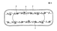
また、線状圧縮部7aであるエンボス圧縮部7により描かれるパターン模様は、円形状、星形状、花びら形状等が連なったパターンなどであってもよい。あるいは例えば図3や図4に示す変形例のように、線状圧縮部7aで非圧縮部18を囲んだ前記各種パターン模様と、長手方向に連続する波線パターンとが組み合わされたものや、前記リーフ状模様のパターンとドット状パターンとが混在したものなど、さまざまなパターンであってよい。
Moreover, the pattern pattern drawn by the
エンボス圧縮部7のパターンは、吸収体3の幅方向の両側縁部6,6にあたる部分の近傍に存在し、かつ、長手方向に連続するパターン、あるいは長手方向に配列する非連続的パターンであって、吸収体3の側縁部6,6の線に対し直角方向に見たときに、すべての範囲もしくはほとんどの部位において、当該側縁部6,6の上およびその外側近傍の領域のいずれかにエンボス圧縮部7が存在するようなものである。
The pattern of the embossed
熱エンボス加工処理によって、エンボス圧縮部7の部分、すなわち線状圧縮部やドット状圧縮部の部分で、不織布は圧密化もしくはフイルム化し、表面材料層1を横方向へ拡散してきた体液の障壁となって横漏れ、滲み出しを防止し、体液はその下の吸収体3の方向へ流れて吸収体3に吸収されることとなる。なお、横漏れ(滲み出し)防止性を確実にするために、表面材料層1が複数枚の不織布で形成されたりあるいは厚みのあるものであっても、熱エンボス加工処理は、エンボス圧縮部7において表面材料層1全体がフイルム化する条件であることが好ましい。
By the heat embossing treatment, the nonwoven fabric is consolidated or filmed at the embossed
このような熱エンボス加工であるから、例えばエンボス圧縮部7が長手方向へ非連続的なエンボスパターンであっても、ほとんどの体液は吸収体3の側縁部6,6の近傍にあたる部分でエンボス圧縮部7に出会い、横方向への移行が止められて吸収体方向へ流れてゆく。また、パンティライナー等が対象とする排泄体液はその量が多くないので、長手方向に配列するエンボス圧縮部7とこれに隣接するエンボス圧縮部7との間のエンボス圧縮部の存在しない隙間が多少あっても、横漏れ、滲み出しはほとんど食い止められる。
Because of such hot embossing, for example, even if the embossed
エンボス圧縮部7は、表面材料層1の吸収体側縁部上およびその外側近傍にあたる領域のいずれかに存在するものであるため、排泄体液の表面材料層1から吸収体3への移行を妨げず、吸収体3のほぼ全面が体液の吸収に有効に使用される。
Since the
また、エンボス圧縮部7は表面材料層1のみに熱エンボス加工処理されているものであるため、当該エンボスが太い線や、円形やリーフ形状の全体が熱エンボス圧密されたり、熱エンボス圧密の面積が大きくても、吸収性物品全体の剛性に及ぼす影響は少ないため使用することは可能であるが、表面材料層1のやわらかい風合いを損なわない範囲でなければならない。
Moreover, since the
また、線状圧縮部となるエンボス圧縮部7は、線の太さが1.Omm以下、好ましくは0.5mm以下の細い線となるように形成されることが好ましく、そのようなものであれば、多数のエンボス圧縮部7を存在させたとしても、表面材料層1のやわらかい風合いを損なうことはなく、吸収性物品全体の剛性に及ぼす影響もほとんどない。すなわち、エンボス圧縮部7は細い線状で形成された線状圧縮部を主体とすることが好ましい。
Further, the embossed
さらに、表面材料層1の熱エンボス加工は、さまざまなデザインのエンボス圧縮部7を外観的に見えるように表面材料層1に施すことができるので、吸収性物品の外見的な美感を生じる結果、使用者に快適感を与えることができる。
Furthermore, since the heat embossing of the surface material layer 1 can be applied to the surface material layer 1 so that the embossed
なお、エンボス圧縮部7は、表面材料層1の風合いの均一性、吸収性物品全体の剛性に与える影響および外見的な美感等の観点から、全体として均一で、規則性のあるエンボスパターンを採用することが好ましい。
The embossed
(吸収体)
吸収体3の材料としては、吸水性の素材であれば特に限定されない。たとえば、フラッフパルプを所定のサイズに積層したものや、それに高吸水性樹脂を加えたもの、あるいは、高吸水性樹勝を含有した親水性のウレタンフォームパルプ、セルローススポンジといった発泡性の吸収素材などが挙げられる。この吸収性物品に用いられる吸収体材料としては、これらの中でも、2層以上のエアレイドパルプの積層構造で、裏面側に行くに従い密度の高い層が設けられたものが好ましい。
(Absorber)
The material of the
本発明の吸収体3の寸法(長さ、幅)は女性の局部とほぼ対等の大きさに設定するのが好ましい。長手方向の長さ寸法は70〜120mm、幅寸法W1は20〜40mmがそのような寸法である。局部に接する領域以外に及ぶ寸法の吸収体3とすると、たとえば製品長手方向全長に吸収体3を配置した場合、局部の凹部への立体的フィット性が損なわれるため、吸収性物品と局部との間に隙間が生じ、体液の漏れを生じる可能性がある。また、動きの多い背臀部で変形し、異物感を感じてしまう。
The dimensions (length and width) of the
前記表面材料層1と裏面材料層2は同じ寸法で、前記吸収体3は長方形で前記両層1,2よりも小さい寸法である。吸収体3の長手方向の寸法は、前記表面材料層1と裏面材料層2の長手方向の全長寸法よりも短く、幅寸法W1は、前記表面材料層1と裏面材料層2の両側縁部すなわち吸収性物品の両側縁部8,8の最も狭い幅寸法よりもさらに短くなっている。吸収体3の側縁部6と側縁部6との間隔の中点は、吸収性物品の側縁部6と側縁部6との間隔の中点に一致している。よって、吸収体3の両側縁部6,6は、吸収性物品の両側縁部8,8よりも内側に位置しており、側縁部6と側縁部8との間隔は5mm以上で15mm以下である。
The surface material layer 1 and the back
この吸収性物品では、前記吸収体3が設けられている領域が中央領域であり、吸収体3の側縁部6と吸収性物品の側縁部6とで挟まれた領域が側部領域である。
In this absorbent article, the region where the
吸収体3は、具体的にはたとえば次のようにしてつくる。
エアレイドパルプで、目付けが160g/m2、厚み1.6mm、寸法は長手方向が100mm、幅寸法W1が30mmのものを使用し、これを140℃オーブンにて1分間熱風処理して厚みを2.Ommとしたものが1枚用いられて吸収体3が得られる。ここで、エアレイドパルプはエアーレイド不織布とも称されるものであり、その構成は、パルプ:87質量%、芯部がPPで鞘部がPEの芯鞘型の複合合成繊維(繊度が1.7dtex、繊維長13mm):13質量%、からなる。鞘部が低融点のPEで形成された前記複合合成繊維は、熱処理によりバインダーの役割を果たす効果がある。あるいは、パルプおよび前記複合合成繊維をバインドする接着剤を用いたものであってもよい。
Specifically, the
Airlaid pulp with a basis weight of 160 g / m 2 , a thickness of 1.6 mm, a length of 100 mm in the longitudinal direction, and a width of W1 of 30 mm is used. . One absorber is used to obtain the
(裏面材料層)
裏面材料層2に用いられる材料は、液不透過性であれば特に限定されない。通気性プラスチックフィルム、非通気性プラスチックフィルム、もしくはスパンボンド不織布/メルトブローン不織布/スパンボンド不織布が積層されて互いに接合されたSMS不織布を用いても良い。
(Back material layer)
The material used for the back
(組み立て用接着剤)
前記表面材料層1、吸収体3、裏面材料層2を相互に貼り合わせて吸収性物品を組み立てて行く際、もしくは表面材料層1、吸収体3を複数の部品で構成する場合の貼り合わせの際、ポリオレフィン系などのホットメルト接着剤等組み立て用接着剤を使用する。組み立て用接着剤としての役割を果たせた上で吸収性物品に剛性を与える影響をできるだけ少なくするよう、接着剤の種類、塗布面積、塗布パターンを選び、塗布量をできるだけ低減することが好ましい。
(Adhesive for assembly)
When assembling an absorbent article by bonding the surface material layer 1, the
(ずれ止め用粘着剤)
裏面材料層2の外側面には、吸収性物品をショーツのクロッチ部に貼り付け、着用中のずれを止めるためのずれ止め用粘着剤5が全面に、もしくは帯状等部分的に塗布される。ずれ止め用粘着剤5としては、水添スチレン・ブタジエンゴム、水添石油系樹脂、パラフィン系オイル等を配合したゴム系粘着剤が好ましく使用される。そして、ずれ止め用粘着剤5の上は離形剤処理された剥離紙で覆われる。
(Slipping prevention adhesive)
On the outer surface of the back
(吸収性物品の全体形状・構造)
この実施の形態の吸収性物品は浅いえぐりの砂時計的形状であり、装着者の腹部及び臀部に当てられる長手方向に向く両端縁部は凸状の曲線形状であり、縦方向に延びる両側縁部8,8は浅い凹状の曲線形状である。吸収性物品の縦方向の長さは、たとえば、最長部位で140mm程度、幅寸法は、長手方向中央部での最端部で45mm程度、長手方向端縁部側の最も広いところで60mm程度であれば好ましく用いられる。
(Overall shape and structure of absorbent articles)
The absorbent article of this embodiment is a shallow hourglass-like shape, both end edges facing the wearer's abdomen and buttocks facing the longitudinal direction are convex curved shapes, and both side edges extending in the longitudinal direction 8 and 8 are shallow concave curved shapes. The length of the absorbent article in the longitudinal direction is, for example, about 140 mm at the longest part, the width dimension is about 45 mm at the extreme end at the center in the longitudinal direction, and about 60 mm at the widest side on the edge in the longitudinal direction. It is preferably used.
本発明の吸収性物品の厚み(中央部)は2.0〜20mmであることが好ましい。2.Omm以下の場合、局部の凹部への立体的なフィット性が低下して、肌との間に隙間を生じるので、体液の漏れ防止効果が低下する。20mm以上の場合、フィット性は向上し、体液の漏れは低減するが体圧が加わった時に使用感を極めて感じやすい。好ましい範囲としては2.5〜5.Ommであり、この範囲であると適度なフィット感を得られ厚みによる漏れへの安心感を得ることができる。 It is preferable that the thickness (central part) of the absorbent article of the present invention is 2.0 to 20 mm. 2. In the case of Omm or less, the three-dimensional fit to the local concave portion is reduced and a gap is formed between the skin and the body fluid leakage preventing effect is reduced. When it is 20 mm or more, the fit is improved and the leakage of body fluid is reduced, but the feeling of use is extremely easy to feel when body pressure is applied. The preferred range is 2.5-5. If it is within this range, an appropriate fit can be obtained and a sense of security against leakage due to thickness can be obtained.
また、吸収性物品の吸収体3が存在する中央領域では、表面材料層1から吸収体3に及ぶ多数の小さな透過孔9が開孔されて、表面材料層1の外面に与えられた体液の吸収体3への透過が促進されるようになっている。
Further, in the central region where the
前記透過孔9は、表面材料層1から吸収体3にかけてピン状の突起を差し込んで、表面材料層1および吸収体3を部分的に破損させることにより、あるいは表面材料層1および吸収体3を部分的に圧縮することにより形成される。図1(B)に示すように、透過孔9の断面形状では、孔内部の側壁部9aに表面材料層1が存在し、底部9bでは表面材料層1が存在していない。または、底部9bに表面材料層1が存在していてもよい。
The transmission hole 9 inserts a pin-shaped protrusion from the surface material layer 1 to the
図2(A)(B)に示すように、透過孔9は中央領域のほぼ全域において規則的に分散している。ただし、透過孔9は、両側のエンボス圧縮部7とエンボス圧縮部7とで挟まれた領域に分散しており、全ての透過孔9がエンボス圧縮部7から離れ、いずれの透過孔9もエンボス圧縮部7と重複しないように形成されている。
As shown in FIGS. 2A and 2B, the transmission holes 9 are regularly dispersed in almost the entire central region. However, the permeation holes 9 are dispersed in a region sandwiched between the embossing
なお、図3および図4に示す例では、透過孔9を特に図示していないが、いずれの例においても、中央領域で且つエンボス圧縮部7と重複しない範囲に、透過孔9が規則的に分散して配列している。
In the examples shown in FIGS. 3 and 4, the transmission holes 9 are not particularly illustrated. However, in any of the examples, the transmission holes 9 are regularly arranged in the central region and in a range not overlapping with the embossed
中央領域に透過孔9が設けられていると、中央領域において表面材料層1の外面に与えられた体液が透過孔9内に流れ込んで吸収体3で吸収されやすくなる。図2,図3および図4に示す例はいずれも、エンボス圧縮部7が、吸収体3の両側部の上から側縁部6を横断して側方領域に渡る範囲、すなわち幅寸法W2の範囲で設け、そして中央領域では、エンボス圧縮部7とエンボス圧縮部7とで挟まれた領域に透過孔9が分散している。したがって、表面材料層1を伝わって側方へ流れあるいは滲む体液は、中央領域の両側において前記エンボス圧縮部7,7で止められるとともに、エンボス圧縮7とエンボス圧縮部7との間で透過孔9を通じて、その下の吸収体3に速やかに吸収される。
When the transmission hole 9 is provided in the central region, the body fluid applied to the outer surface of the surface material layer 1 in the central region flows into the transmission hole 9 and is easily absorbed by the
このように、吸収体3が設けられた中央領域の両側部に位置するエンボス圧縮部7,7の液遮断機能と、中央領域の透過孔9の液機能とが相俟って、吸収性物品の横方向への体液の滲み出しや漏れが防止でき、また体液の吸収性が一層高まる。
As described above, the liquid blocking function of the embossed
図の実施の形態では、前記エンボス圧縮部7がリーフ状模様などであり、エンボス圧縮部7が設けられている領域は、吸収体3の両側部の上から側縁部6を横断して側部領域に渡る幅寸法がW2の範囲である。よって、表面材料層1には側縁部6を含む幅寸法がW2の範囲において、長手方向の全長に渡って液遮断帯が形成されているのと同じになる。この液遮断帯により、中央領域から側方へ流れ出ようとするあるいは滲み出ようとする体液を止めることができる。しかも前記液遮断帯内では、線状圧縮部やドット圧縮部が設けられて、前記液遮断帯内でのエンボス圧縮部7の占める面積が小さくなっているため、前述のように吸収性物品にゴワツキ感を生じさせることがない。
In the illustrated embodiment, the embossed
前記液遮断帯の幅寸法W2は3mm以上で10mm以下が好ましい。3mm未満であると、液遮断帯内でエンボス圧縮部7の占める面積率が高くなってゴワツキ感の原因になりやすく、また10mmを超えると中央領域での実質的な液吸収機能を発揮する領域を狭めることになる。
The width W2 of the liquid blocking zone is preferably 3 mm or more and 10 mm or less. If the area is less than 3 mm, the area ratio occupied by the embossed
また、両側のエンボス圧縮部7とエンボス圧縮部7とで挟まれた領域の幅寸法W3は、吸収体3の幅寸法W1の0.6倍以上が好ましい。この範囲であれば、表面材料層1の液を透過させる領域を充分に確保できる。
Further, the width dimension W3 of the region sandwiched between the
(吸収性物品の製造方法)
前記吸収性物品は、この分野において通常採用されている材料供給、吸収性物品組立等の工程を経て製造することができる。
(Method for manufacturing absorbent article)
The said absorbent article can be manufactured through processes, such as material supply and an absorbent article assembly which are normally employ | adopted in this field | area.
たとえば、次のような製造工程が例示できる。1枚または複数枚の不織布を嵩回復処理をした後(後者の場合貼り合わせる)、所定位置に本発明の熱エンボス加工を施して表面材料層1のシートを得る。別工程でつくられ、所定寸法にカットされた吸収体3が、表面材料層1と貼り合わされる。吸収体3部分に表面材料層1の上からの透過孔9が施される場合は、この貼り合わせ工程の後に行われる。次に、ずれ止め用粘着剤5、剥離紙がつけられた裏面材料層2が貼り合わされる。以後、プレスロール、カッター等を経て、最終製品である吸収性物品となる。
For example, the following manufacturing process can be illustrated. One or a plurality of non-woven fabrics are subjected to bulk recovery treatment (bonded in the latter case), and then subjected to the hot embossing of the present invention at a predetermined position to obtain a sheet of the surface material layer 1. The
1 表面材料層
2 裏面材料層
3 吸収体
4 周縁部接合手段
5 ずれ止め用粘着剤
6 吸収体の側縁部
7 エンボス圧縮部
7a 線状圧縮部
8 吸収性物品の側縁部
18 非圧縮部
DESCRIPTION OF SYMBOLS 1
Claims (9)
前記表面材料層は、熱風処理によって嵩を回復した不織布で形成され、
前記吸収体は、前記表面材料層および裏面材料層よりも幅寸法が狭く、前記吸収体の長手方向に延びる側縁部が、前記表面材料層および裏面材料層の側縁部よりも内側に位置しており、
前記吸収体が設けられている領域を中央領域、前記吸収体の側縁部と前記表面材料層および裏面材料層の側縁部との間を側部領域としたときに、
前記中央領域の両側部に、前記表面材料層のみを圧縮したエンボス圧縮部が、前記長手方向に向けて連続しまたは前記長手方向に向けて配列して形成されており、前記エンボス圧縮部は、前記吸収体のそれぞれの前記側縁部を跨いで、前記中央領域から前記側部領域にわたる幅寸法で形成されていることを特徴とする吸収性物品。 A liquid permeable surface material layer, a liquid impermeable back material layer, the absorbent article having a arranged absorber between the two material layers,
The surface material layer is formed of a nonwoven fabric whose bulk has been recovered by hot air treatment,
The absorbent body has a narrower width dimension than the surface material layer and the back surface material layer, and a side edge portion extending in a longitudinal direction of the absorber is positioned inside a side edge portion of the surface material layer and the back surface material layer. And
When the region where the absorber is provided is a central region, and the side region between the side edge of the absorber and the side edge of the surface material layer and the back surface material layer,
Embossed compression parts that compress only the surface material layer are formed on both sides of the central region, and are formed continuously in the longitudinal direction or arranged in the longitudinal direction . An absorbent article having a width dimension extending from the central region to the side region, straddling each side edge of the absorbent body .
前記表面材料層と液不透過性の裏面材料層との間に、前記表面材料層および前記裏面材料層よりも幅寸法が狭い吸収体を配置する工程とを有し、
前記吸収体の長手方向に延びる側縁部が、前記表面材料層および裏面材料層の側縁部よりも内側に位置し、前記エンボス圧縮部が前記吸収体の側縁部を跨いで、前記吸収体が設けられている中央領域から、前記吸収体の側縁部と前記表面材料層および裏面材料層の側縁部との間の側部領域にわたる幅寸法で形成される吸収性物品を製造することを特徴とする吸収性物品の製造方法。 A step of forming a surface material layer in which an embossed compression portion is formed that recovers the bulk of a liquid-permeable nonwoven fabric with hot air and is continuous in the longitudinal direction or arranged in the longitudinal direction;
A step of disposing an absorber having a narrower width dimension than the surface material layer and the back surface material layer between the surface material layer and the liquid-impermeable back surface material layer;
A side edge portion extending in the longitudinal direction of the absorbent body is positioned inside a side edge portion of the surface material layer and the back surface material layer, and the embossed compression portion straddles the side edge portion of the absorbent body. An absorbent article formed with a width dimension extending from a central region where a body is provided to a side region between a side edge of the absorbent body and a side edge of the surface material layer and the back surface material layer is manufactured. The manufacturing method of the absorbent article characterized by the above-mentioned.
Priority Applications (1)
| Application Number | Priority Date | Filing Date | Title |
|---|---|---|---|
| JP2008006296A JP4693847B2 (en) | 2002-03-26 | 2008-01-15 | Absorbent article and manufacturing method thereof |
Applications Claiming Priority (3)
| Application Number | Priority Date | Filing Date | Title |
|---|---|---|---|
| JP2002085004 | 2002-03-26 | ||
| JP2002085004 | 2002-03-26 | ||
| JP2008006296A JP4693847B2 (en) | 2002-03-26 | 2008-01-15 | Absorbent article and manufacturing method thereof |
Related Parent Applications (1)
| Application Number | Title | Priority Date | Filing Date |
|---|---|---|---|
| JP2002335126A Division JP4278963B2 (en) | 2002-03-26 | 2002-11-19 | Absorbent articles |
Publications (3)
| Publication Number | Publication Date |
|---|---|
| JP2008100110A JP2008100110A (en) | 2008-05-01 |
| JP2008100110A5 JP2008100110A5 (en) | 2008-07-03 |
| JP4693847B2 true JP4693847B2 (en) | 2011-06-01 |
Family
ID=39434848
Family Applications (1)
| Application Number | Title | Priority Date | Filing Date |
|---|---|---|---|
| JP2008006296A Expired - Lifetime JP4693847B2 (en) | 2002-03-26 | 2008-01-15 | Absorbent article and manufacturing method thereof |
Country Status (1)
| Country | Link |
|---|---|
| JP (1) | JP4693847B2 (en) |
Cited By (15)
| Publication number | Priority date | Publication date | Assignee | Title |
|---|---|---|---|---|
| WO2013150921A1 (en) | 2012-04-02 | 2013-10-10 | ユニ・チャーム株式会社 | Absorbent article |
| US9233185B2 (en) | 2012-03-30 | 2016-01-12 | Unicharm Corporation | Absorbent article |
| US9301885B2 (en) | 2011-04-28 | 2016-04-05 | Unicharm Corporation | Absorbent article |
| US9314383B2 (en) | 2012-03-30 | 2016-04-19 | Unicharm Corporation | Absorptive article |
| US9351887B2 (en) | 2012-04-02 | 2016-05-31 | Unicharm Corporation | Absorbent article |
| US9375356B2 (en) | 2012-04-02 | 2016-06-28 | Unicharm Corporation | Absorbent article |
| US9375365B2 (en) | 2012-02-29 | 2016-06-28 | Unicharm Corporation | Absorbent article |
| US9381268B2 (en) | 2012-04-02 | 2016-07-05 | Unicharm Corporation | Absorbent article |
| US9387135B2 (en) | 2012-02-29 | 2016-07-12 | Unicharm Corporation | Absorbent article |
| US9498387B2 (en) | 2012-02-29 | 2016-11-22 | Unicharm Corporation | Absorbent article having bent sections |
| US9770526B2 (en) | 2011-09-30 | 2017-09-26 | Unicharm Corporation | Absorbent article |
| US9775751B2 (en) | 2012-02-29 | 2017-10-03 | Unicharm Corporation | Absorbent article |
| US10278873B2 (en) | 2011-12-28 | 2019-05-07 | Unicharm Corporation | Absorbent article having a domed section and method of manufacturing same |
| US10322037B2 (en) | 2012-02-29 | 2019-06-18 | Unicharm Corporation | Absorbent article |
| US10543132B2 (en) | 2011-03-31 | 2020-01-28 | Unicharm Corporation | Absorbent article with blood modifying agent |
Families Citing this family (4)
| Publication number | Priority date | Publication date | Assignee | Title |
|---|---|---|---|---|
| JP6073101B2 (en) * | 2012-09-30 | 2017-02-01 | ユニ・チャーム株式会社 | Absorbent articles |
| JP5707467B2 (en) | 2013-10-18 | 2015-04-30 | ユニ・チャーム株式会社 | Absorbent article manufacturing apparatus and method of remodeling manufacturing apparatus |
| JP5753884B2 (en) | 2013-10-18 | 2015-07-22 | ユニ・チャーム株式会社 | Absorbent article manufacturing apparatus and manufacturing method |
| JP6286388B2 (en) * | 2015-05-01 | 2018-02-28 | ユニ・チャーム株式会社 | Absorbent article manufacturing apparatus and manufacturing method |
Citations (8)
| Publication number | Priority date | Publication date | Assignee | Title |
|---|---|---|---|---|
| JPS55127712U (en) * | 1979-03-07 | 1980-09-09 | ||
| JPH02210053A (en) * | 1989-02-07 | 1990-08-21 | Daiwabo Co Ltd | Bulky nonwoven fabric and body fluid-absorbing article having the same on surface layer |
| JPH05154176A (en) * | 1991-12-09 | 1993-06-22 | Kao Corp | Sanitary napkin |
| JPH06294059A (en) * | 1993-04-02 | 1994-10-21 | Daiwabo Co Ltd | Patterned spun lace nonwoven fabric and its production |
| JPH1077566A (en) * | 1996-07-11 | 1998-03-24 | Uni Charm Corp | Nonwoven fabric and its production |
| JPH11197179A (en) * | 1998-01-09 | 1999-07-27 | Shiseido Co Ltd | Sanitary article |
| JP2000210334A (en) * | 1999-01-20 | 2000-08-02 | Uni Charm Corp | Throw-away absorptive article for body fluid treatment |
| JP2000255645A (en) * | 1999-03-08 | 2000-09-19 | Asahi Chem Ind Co Ltd | Food carrying sheet and its manufacture |
-
2008
- 2008-01-15 JP JP2008006296A patent/JP4693847B2/en not_active Expired - Lifetime
Patent Citations (8)
| Publication number | Priority date | Publication date | Assignee | Title |
|---|---|---|---|---|
| JPS55127712U (en) * | 1979-03-07 | 1980-09-09 | ||
| JPH02210053A (en) * | 1989-02-07 | 1990-08-21 | Daiwabo Co Ltd | Bulky nonwoven fabric and body fluid-absorbing article having the same on surface layer |
| JPH05154176A (en) * | 1991-12-09 | 1993-06-22 | Kao Corp | Sanitary napkin |
| JPH06294059A (en) * | 1993-04-02 | 1994-10-21 | Daiwabo Co Ltd | Patterned spun lace nonwoven fabric and its production |
| JPH1077566A (en) * | 1996-07-11 | 1998-03-24 | Uni Charm Corp | Nonwoven fabric and its production |
| JPH11197179A (en) * | 1998-01-09 | 1999-07-27 | Shiseido Co Ltd | Sanitary article |
| JP2000210334A (en) * | 1999-01-20 | 2000-08-02 | Uni Charm Corp | Throw-away absorptive article for body fluid treatment |
| JP2000255645A (en) * | 1999-03-08 | 2000-09-19 | Asahi Chem Ind Co Ltd | Food carrying sheet and its manufacture |
Cited By (17)
| Publication number | Priority date | Publication date | Assignee | Title |
|---|---|---|---|---|
| US10543132B2 (en) | 2011-03-31 | 2020-01-28 | Unicharm Corporation | Absorbent article with blood modifying agent |
| US9301885B2 (en) | 2011-04-28 | 2016-04-05 | Unicharm Corporation | Absorbent article |
| US9770526B2 (en) | 2011-09-30 | 2017-09-26 | Unicharm Corporation | Absorbent article |
| US10278873B2 (en) | 2011-12-28 | 2019-05-07 | Unicharm Corporation | Absorbent article having a domed section and method of manufacturing same |
| US9775751B2 (en) | 2012-02-29 | 2017-10-03 | Unicharm Corporation | Absorbent article |
| US10772770B2 (en) | 2012-02-29 | 2020-09-15 | Unicharm Corporation | Absorbent article |
| US10322037B2 (en) | 2012-02-29 | 2019-06-18 | Unicharm Corporation | Absorbent article |
| US9375365B2 (en) | 2012-02-29 | 2016-06-28 | Unicharm Corporation | Absorbent article |
| US9387135B2 (en) | 2012-02-29 | 2016-07-12 | Unicharm Corporation | Absorbent article |
| US9498387B2 (en) | 2012-02-29 | 2016-11-22 | Unicharm Corporation | Absorbent article having bent sections |
| US9233185B2 (en) | 2012-03-30 | 2016-01-12 | Unicharm Corporation | Absorbent article |
| US9314383B2 (en) | 2012-03-30 | 2016-04-19 | Unicharm Corporation | Absorptive article |
| US9339423B2 (en) | 2012-04-02 | 2016-05-17 | Unicharm Corporation | Absorbent article |
| US9381268B2 (en) | 2012-04-02 | 2016-07-05 | Unicharm Corporation | Absorbent article |
| US9375356B2 (en) | 2012-04-02 | 2016-06-28 | Unicharm Corporation | Absorbent article |
| US9351887B2 (en) | 2012-04-02 | 2016-05-31 | Unicharm Corporation | Absorbent article |
| WO2013150921A1 (en) | 2012-04-02 | 2013-10-10 | ユニ・チャーム株式会社 | Absorbent article |
Also Published As
| Publication number | Publication date |
|---|---|
| JP2008100110A (en) | 2008-05-01 |
Similar Documents
| Publication | Publication Date | Title |
|---|---|---|
| JP4693847B2 (en) | Absorbent article and manufacturing method thereof | |
| JP4278963B2 (en) | Absorbent articles | |
| JP4323786B2 (en) | Absorbent article with vertically long compressed groove | |
| JP2514294B2 (en) | Body side cover for absorbent articles | |
| KR100971193B1 (en) | An absorbent body and an absorbent article using the same | |
| EP2478881B1 (en) | Absorptive article | |
| EP2087866A1 (en) | Absorptive article and method of producing the same | |
| JP2010104547A (en) | Absorbent article and method of manufacturing the same | |
| TWI419678B (en) | Absorbent items | |
| KR102549764B1 (en) | Absorbent core layers and absorbent personal care articles containing such layers | |
| JP4712533B2 (en) | Absorbent articles | |
| US8211075B2 (en) | Interlabial pad | |
| WO2017199419A1 (en) | Absorbent article | |
| JP6073619B2 (en) | Absorbent articles | |
| JP5405798B2 (en) | Absorbent articles | |
| JP5957240B2 (en) | Method for manufacturing absorbent article | |
| KR102642080B1 (en) | absorbent article | |
| JP4145692B2 (en) | Absorbent articles | |
| JP7109942B2 (en) | absorbent article | |
| JP2005349051A (en) | Inter-labia pad | |
| JPH03199401A (en) | Excessive milk-absorbing pad |
Legal Events
| Date | Code | Title | Description |
|---|---|---|---|
| A621 | Written request for application examination |
Free format text: JAPANESE INTERMEDIATE CODE: A621 Effective date: 20080115 |
|
| A521 | Request for written amendment filed |
Free format text: JAPANESE INTERMEDIATE CODE: A523 Effective date: 20080521 |
|
| A977 | Report on retrieval |
Free format text: JAPANESE INTERMEDIATE CODE: A971007 Effective date: 20100512 |
|
| A131 | Notification of reasons for refusal |
Free format text: JAPANESE INTERMEDIATE CODE: A131 Effective date: 20100518 |
|
| A521 | Request for written amendment filed |
Free format text: JAPANESE INTERMEDIATE CODE: A523 Effective date: 20100714 |
|
| TRDD | Decision of grant or rejection written | ||
| A01 | Written decision to grant a patent or to grant a registration (utility model) |
Free format text: JAPANESE INTERMEDIATE CODE: A01 Effective date: 20110215 |
|
| A01 | Written decision to grant a patent or to grant a registration (utility model) |
Free format text: JAPANESE INTERMEDIATE CODE: A01 |
|
| A61 | First payment of annual fees (during grant procedure) |
Free format text: JAPANESE INTERMEDIATE CODE: A61 Effective date: 20110222 |
|
| FPAY | Renewal fee payment (event date is renewal date of database) |
Free format text: PAYMENT UNTIL: 20140304 Year of fee payment: 3 |
|
| R150 | Certificate of patent or registration of utility model |
Ref document number: 4693847 Country of ref document: JP Free format text: JAPANESE INTERMEDIATE CODE: R150 Free format text: JAPANESE INTERMEDIATE CODE: R150 |
|
| R250 | Receipt of annual fees |
Free format text: JAPANESE INTERMEDIATE CODE: R250 |
|
| R250 | Receipt of annual fees |
Free format text: JAPANESE INTERMEDIATE CODE: R250 |
|
| R250 | Receipt of annual fees |
Free format text: JAPANESE INTERMEDIATE CODE: R250 |
|
| R250 | Receipt of annual fees |
Free format text: JAPANESE INTERMEDIATE CODE: R250 |
|
| R250 | Receipt of annual fees |
Free format text: JAPANESE INTERMEDIATE CODE: R250 |
|
| R250 | Receipt of annual fees |
Free format text: JAPANESE INTERMEDIATE CODE: R250 |
|
| R250 | Receipt of annual fees |
Free format text: JAPANESE INTERMEDIATE CODE: R250 |
|
| R250 | Receipt of annual fees |
Free format text: JAPANESE INTERMEDIATE CODE: R250 |
|
| R250 | Receipt of annual fees |
Free format text: JAPANESE INTERMEDIATE CODE: R250 |
|
| EXPY | Cancellation because of completion of term |