JP4691105B2 - Executing checker instructions in a redundant multithreaded environment - Google Patents
Executing checker instructions in a redundant multithreaded environment Download PDFInfo
- Publication number
- JP4691105B2 JP4691105B2 JP2007533793A JP2007533793A JP4691105B2 JP 4691105 B2 JP4691105 B2 JP 4691105B2 JP 2007533793 A JP2007533793 A JP 2007533793A JP 2007533793 A JP2007533793 A JP 2007533793A JP 4691105 B2 JP4691105 B2 JP 4691105B2
- Authority
- JP
- Japan
- Prior art keywords
- thread
- instruction
- checker
- tracking
- instructions
- Prior art date
- Legal status (The legal status is an assumption and is not a legal conclusion. Google has not performed a legal analysis and makes no representation as to the accuracy of the status listed.)
- Expired - Fee Related
Links
Images


Classifications
-
- G—PHYSICS
- G06—COMPUTING; CALCULATING OR COUNTING
- G06F—ELECTRIC DIGITAL DATA PROCESSING
- G06F11/00—Error detection; Error correction; Monitoring
- G06F11/07—Responding to the occurrence of a fault, e.g. fault tolerance
- G06F11/14—Error detection or correction of the data by redundancy in operation
- G06F11/1479—Generic software techniques for error detection or fault masking
- G06F11/1492—Generic software techniques for error detection or fault masking by run-time replication performed by the application software
- G06F11/1494—N-modular type
-
- G—PHYSICS
- G06—COMPUTING; CALCULATING OR COUNTING
- G06F—ELECTRIC DIGITAL DATA PROCESSING
- G06F11/00—Error detection; Error correction; Monitoring
- G06F11/07—Responding to the occurrence of a fault, e.g. fault tolerance
- G06F11/16—Error detection or correction of the data by redundancy in hardware
- G06F11/1695—Error detection or correction of the data by redundancy in hardware which are operating with time diversity
Description
現在の冗長実行システムは一般に、自己検査式であり且つハードウェアで実装されるチェッカ回路を採用している。チェッカ回路に類似するのは、2つのスレッド(たとえば、ストアアドレス及びデータ)からの結果を比較する比較命令である。両方のスレッドで比較命令を複製し、複製を介して自己検査の効果を得ることが可能であり得る。
不都合なことに、比較命令を複製することにより、アーキテクチャは冗長マルチスレッド(RMT)の性能利点を失うことになる。RMTの性能利点は、先行スレッドが追跡スレッドのキャッシュミス及び分岐予測をプリフェッチできるように十分に離れた先行スレッド及び追跡スレッドを有することから生じる。比較命令が複製される場合、キューの追加が必要なだけでなく(より高いオーバーヘッドを招く)、アーキテクチャは、両方向で求められる同期により2つのスレッドを十分離れた状態で保持することができなくなり得る。したがって、必要なのは、RMTの性能利点を犠牲にすることなくより低い故障率を実現できる命令である。 Unfortunately, by duplicating the compare instructions, the architecture loses the performance advantage of redundant multithreading (RMT). Performance advantages of RMT results from the preceding thread has sufficient distant preceding thread and tracking threads to allow prefetch cache misses and branch prediction tracking thread. When the compare instruction is replicated, not only does the queue need to be added (incurs higher overhead), but the architecture may not be able to keep the two threads well apart due to the synchronization required in both directions. . Therefore, what is needed is an instruction that can achieve a lower failure rate without sacrificing the performance benefits of RMT.
本発明の各種特徴が、同様の参照番号が概して全図面を通して同じパーツを指す添付図面に示す好ましい実施形態の以下の説明から明らかになろう。図面は必ずしも一定の縮尺で描かれておらず、それに代えて本発明の原理を示すことに重点が置かれている。 Various features of the present invention will become apparent from the following description of preferred embodiments, as illustrated in the accompanying drawings, in which like reference numerals generally refer to the same parts throughout the drawings. The drawings are not necessarily drawn to scale, emphasis instead being placed on illustrating the principles of the invention.
以下の説明では、限定ではなく説明のために、特定の構造、アーキテクチャ、インタフェース、技法等の特定の詳細を記して、本発明の各種態様の完全な理解を提供する。しかし、本発明の各種態様を他の例ではこれら特定の詳細から離れて実施可能なことが、本開示の恩恵を受ける当業者には明白であろう。特定の場合では、本発明の説明を不必要な詳細で曖昧にしないように、既知の装置、回路、及び方法についての説明を省いている。 In the following description, for purposes of explanation and not limitation, specific details are set forth such as specific structures, architectures, interfaces, techniques, etc., to provide a thorough understanding of various aspects of the invention. However, it will be apparent to those skilled in the art having the benefit of this disclosure that various aspects of the present invention may be practiced in other examples apart from these specific details. In certain instances, descriptions of known devices, circuits, and methods are omitted so as not to obscure the description of the present invention with unnecessary detail.
冗長マルチスレッド環境でのチェッカ命令の方法及び装置について記載する。以下の説明では、説明のために、多くの特定の詳細を記して本発明の完全な理解を提供する。しかし、本発明をこれら特定の詳細なしで実施可能なことが当業者には明白であろう。 A method and apparatus for checker instructions in a redundant multithreaded environment is described. In the following description, for the purposes of explanation, numerous specific details are set forth in order to provide a thorough understanding of the present invention. However, it will be apparent to those skilled in the art that the present invention may be practiced without these specific details.
図1は、冗長マルチスレッドアーキテクチャの一実施形態のブロック図である。冗長マルチスレッドアーキテクチャでは、故障は、プログラムの2つのコピーを別個のスレッドとして実行することによって検出することができる。 FIG. 1 is a block diagram of one embodiment of a redundant multithreaded architecture. In a redundant multithreaded architecture, a failure can be detected by running the two copies of the program as separate threads.
各スレッドには同一の入力が提供され、出力が比較されて、エラーが発生したか否かが判断される。冗長マルチスレッドは、本明細書では「複製範囲(sphere of replication)」と呼ぶ概念に関連して説明することができる。複製範囲とは、論理的又は物理的な冗長動作の境界である。 Each thread is provided with the same input and the outputs are compared to determine if an error has occurred. Redundant multithreading can be described in connection with a concept referred to herein as a “sphere of replication”. The duplication range is a boundary of logical or physical redundant operation.
複製範囲100内の構成要素(たとえば、先行スレッド105を実行しているプロセッサ及び追跡スレッド110を実行しているプロセッサ)が冗長実行の対象である。これとは対照的に、複製範囲100外の構成要素(たとえば、メモリ115)は冗長実行の対象ではない。故障保護は他の技法、たとえばメモリ115の誤り修正符号によって提供される。他の装置は複製範囲100外であってもよく、且つ/又は他の技法を使用して故障保護を複製範囲100外の装置に提供することができる。
Components within the replication range 100 (for example, the processor executing the preceding
複製範囲100に入るデータは、データを複製し且つデータのコピーを先行スレッド105及び追跡スレッド110に送る入力複製エージェント120を通して入る。同様に、複製範囲100を出るデータは、データを比較し且つエラーが発生したか否かを判断する出力比較エージェント125を通って出る。複製範囲100の境界の変更は、性能とハードウェア量との間のトレードオフである。たとえば、メモリ115を複製すると、ストア命令の出力比較を避けることによりメモリへのより高速でのアクセスが可能になるが、システムでのメモリ量を2倍にすることによってシステムコストが増大する。
Data entering
本発明の一実施形態は、RMTのソフトウェア実装でのチェッカ回路を検査するメカニズムを提案する。RMTはコミットされた命令の出力を比較する(命令毎の比較を必要とする)ため、これはソフトウェアで実装することもできる。RMTのソフトウェア実装があらゆる命令を比較する場合、相当なオーバーヘッドが発生する。しかしそれに代えて、RMTは、ストア命令のみの比較及びロード命令のみの複製を可能にし、これはRMT実装のソフトウェアオーバーヘッドを大幅に低減することができる。 One embodiment of the present invention proposes a mechanism for inspecting a checker circuit in a software implementation of RMT. Since RMT compares the output of committed instructions (requires a per-instruction comparison), this can also be implemented in software. When the RMT software implementation compares every instruction, considerable overhead occurs. Instead, however, RMT allows comparison of store instructions only and replication of load instructions only, which can significantly reduce the software overhead of the RMT implementation.
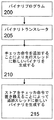
図2は、チェッカ命令を生成する一方法を示す。まず、大半のコンピュータでのようにコンパイラが命令を生成する。コンパイラから、コンピュータはここで、一連のストア命令であり得るがこれに限定されないバイナリプログラムを有する(200)。次に、バイナリトランスレータがバイナリプログラム中の各ストア命令の前にチェッカ命令を挿入することができる(205)。バイナリトランスレータは当該技術分野において既知の任意のバイナリトランスレータであってもよい。バイナリプログラムの変換後、システムは先行スレッド及び追跡スレッドの両方にバイナリプログラムを作成する。先行スレッドのバイナリプログラムは、チェッカ命令をストア命令に追加する(210)。追跡スレッドのバイナリプログラムは、ストア命令を先行スレッドのピアチェッカ命令で置き換える(215)。 FIG. 2 illustrates one method for generating checker instructions. First, the compiler generates instructions, as on most computers. From the compiler, the computer now has a binary program that can be, but is not limited to, a series of store instructions (200). Next, the binary translator can insert a checker instruction before each store instruction in the binary program (205). The binary translator may be any binary translator known in the art. After conversion of the binary program, the system creates a binary program in both the predecessor thread and the tracking thread. The binary program of the preceding thread adds a checker instruction to the store instruction (210). The binary program of the tracking thread replaces the store instruction with the peer checker instruction of the preceding thread (215).
図3は、チェッカ命令の一実施態様を示す。RMTが比較を要求すると、プロセッサはチェッカ命令を先行スレッド及び追跡スレッドの両方において発することができる(300)。各チェッカ命令は各スレッドから64ビット量を伝達することができる。チェッカ命令は、各パイプラインの終わりにあるバッファに達するまで各スレッドの個々のパイプラインを独立して移行することができる(305)。チェッカ命令は、ピアチェッカ命令をバッファで待つ(310)。これら2つのチェッカ命令は次いで、伝達している64ビット量の比較を行うことができる(315)。一致しない場合、両方がエラーを報告することができる。一致する場合、プロセッサにチェッカ命令をコミットさせることができる(320)。パイプラインは、CMP中の異なるプロセッサからであっても、又はSMTプロセッサと同じマルチスレッドプロセッサからであってもよい。 FIG. 3 illustrates one embodiment of a checker instruction. When the RMT requests a comparison, the processor can issue a checker instruction in both the predecessor thread and the trace thread (300). Each checker instruction can carry a 64-bit quantity from each thread. The checker instruction can independently transition each thread's individual pipeline until it reaches a buffer at the end of each pipeline (305). The checker instruction waits in a buffer for a peer checker instruction (310). These two checker instructions can then perform a comparison of the amount of 64 bits being transmitted (315). If they do not match, both can report an error. If there is a match, the processor can commit the checker instruction (320). The pipeline may be from a different processor during CMP or from the same multithreaded processor as the SMT processor.
この実施態様では、チェッカ命令は、命令キューからの処理命令からの先行する命令を中断しない。むしろ、リタイアポインタのみを、追跡スレッドからの対応するチェッカ命令が現れるまで中断するだけである。また、環境がRMT環境ではない場合、チェッカ命令はNOPとして扱われることができる。 In this embodiment, the checker instruction does not interrupt the preceding instruction from the processing instruction from the instruction queue. Rather, it only suspends the retire pointer until a corresponding checker instruction from the tracking thread appears. Also, if the environment is not an RMT environment, the checker instruction can be treated as a NOP.
図4は、2つのパイプラインを通って流れるチェッカ命令の一例のブロック図である。ストア命令R1→[R2]が、レジスタR1中の値をレジスタR2中のアドレスによってポイントされるメモリロケーションに記憶するものと仮定する。このストア命令は、チェッカ命令と共に先行スレッド及び追跡スレッドの両方で複製することができる。先行スレッドのストア命令は、チェッカ命令及びストア命令の両方を以下に示すように含むことができる。
Checkerinst R1
Checkerinst R2
Store: R1→[R2]
したがって、先行スレッドは、パイプライン400を移行する時にストア命令とともにチェッカ命令を含むことができる。
FIG. 4 is a block diagram of an example of a checker instruction that flows through two pipelines. Assume that the store instruction R1 → [R2] stores the value in register R1 in the memory location pointed to by the address in register R2. This store instruction can be replicated in both the predecessor thread and the tracking thread along with the checker instruction. The preceding thread store instructions can include both checker instructions and store instructions as shown below.
Checkerinst R1
Checkerinst R2
Store: R1 → [R2]
Thus, the predecessor thread can include a checker instruction along with a store instruction when transitioning through the
追跡スレッドのストア命令は、以下に示すようにチェッカ命令のみを含むことができる。
Checkerinst R1
Checkerinst R2
したがって、追跡スレッドはパイプライン405を通って移行するストア命令を有さない。
The store instruction of the tracking thread can include only a checker instruction as shown below.
Checkerinst R1
Checkerinst R2
Thus, the tracking thread does not have store instructions that migrate through
パイプライン400中の先行スレッドからのcheckerinst R1は、バッファ410においてピアチェッカ命令を待つ。パイプライン405中の追跡スレッドからのcheckerinst R1は、バッファ415においてピアチェッカ命令を待つ。チェッカ命令は常にその相手方すなわちピアを探すか、又は待つ。ミラースレッドがある場合、チェッカ命令はバッファ410、405においてそのスレッドを探すか、又は待ち、ミラースレッドがそこにあることを確認してから、チェッカ命令を比較する。
Checkerinst R1 from the preceding thread in
先行スレッドからのcheckerinst R1及び追跡スレッドからのcheckerinst R1は、コミット順によりペアになることができ、レジスタ指示子とR1の値を比較して、レジスタがいずれのエラーも有さなかったことを保証する。エラーが見つからない場合、チェッカ命令はコミットされる(420)。チェッカ命令がコミットされると、R1の値が記憶される。R1の値は、コミットポイントを通ってから記憶される。したがって、システムは、従来のように検査をストア毎に行うのではなくすべてのストアを同時に検査することができる。 Checkerinst R1 from the predecessor thread and checkerinst R1 from the tracking thread can be paired according to commit order, comparing the register specifier and the value of R1 to ensure that the register did not have any errors To do. If no error is found, the checker instruction is committed (420). When the checker instruction is committed, the value of R1 is stored. The value of R1 is stored after passing through the commit point. Thus, the system can inspect all stores simultaneously, rather than performing the inspection for each store as is conventional.
図5は、マルチスレッドプロセッサ用の環境を提供することができるシステムのブロック図である。図5に示すシステムは或る範囲のシステムを表すことを意図される。代替のシステムは、より多数、より少数、且つ/又は異なる構成要素を備えることができる。 FIG. 5 is a block diagram of a system that can provide an environment for a multi-threaded processor. The system shown in FIG. 5 is intended to represent a range of systems. Alternative systems can include more, fewer, and / or different components.
システム500は、情報を伝達するバス510又は他の通信装置、及びバス510に結合されて情報を処理するプロセッサ(複数可)520を備える。システム500は、メモリコントローラ530を介してバス510に結合されて、情報及びプロセッサ(複数可)520が実行する命令を記憶するランダムアクセスメモリ(RAM)又は他のダイナミックメモリ並びにスタティックメモリ、たとえばハードディスク又は他の記憶装置535(メモリと呼ぶ)をさらに備える。メモリ535はまた、プロセッサ(複数可)520による命令の実行中に一時変数又は他の中間情報を記憶するためにも使用することができる。メモリコントローラ530は、1つ又は複数の種類のメモリ及び/又は関連するメモリ装置を制御する1つ又は複数の構成要素を備えることができる。システム500は、バス510に結合されてプロセッサ(複数可)520のためにスタティックな情報及び命令を記憶する読み取り専用メモリ(ROM)及び/又は他のスタティック記憶装置540も備える。
システム500はまた、バス510を介して入/出力(I/O)インタフェース550にも結合することができる。I/Oインタフェース550はI/O装置555へのインタフェースを提供し、I/O装置555はたとえば、コンピュータユーザに情報を表示する陰極線管(CRT)又は液晶ディスプレイ(LCD)、英数字及び他のキーを含む英数字入力装置、並びに/或いはマウス、トラックボール、又はカーソル方向キー等のカーソル制御装置を含むことができる。システム500は、ローカルエリアネットワーク等のネットワークへのアクセスを有無線で提供するネットワークインタフェース560をさらに備える。
命令は、メモリ535に磁気ディスク、読み取り専用メモリ(ROM)集積回路、CD−ROM、DVD等の記憶装置から、有無線のリモート接続(たとえば、ネットワークインタフェース860を介してネットワーク経由で)等を介して提供される。 The instructions are stored in the memory 535 from a storage device such as a magnetic disk, a read-only memory (ROM) integrated circuit, a CD-ROM, a DVD, etc. via a wired / wireless remote connection (for example, via a network via the network interface 860), Provided.
これより図6を参照すると、システム600は概して、プロセッサ、メモリ、及び入/出力装置が複数のポイントツーポイントインタフェースによって相互接続されるシステムを示す。システム600はいくつかのプロセッサも備えることができ、明瞭にするために、そのうちの2つプロセッサ605、610のみを示す。プロセッサ605、610はそれぞれ、ローカルメモリコントローラハブ(MCH)615、620を備えてメモリ625、630と接続することができる。プロセッサ605、610は、ポイントツーポイントインタフェース回路640、645を使用して、ポイントツーポイントインタフェース635を介してデータを交換することができる。プロセッサ605、610はそれぞれ、ポイントツーポイントインタフェース回路665、670、675、680を使用して、個々のポイントツーポイントインタフェース655、660を介してチップセット650とデータを交換することができる。チップセット650はまた、高性能グラフィックスインタフェース690を介して高性能グラフィックス回路685とデータを交換することもできる。
Referring now to FIG. 6, system 600 generally illustrates a system in which processors, memory, and input / output devices are interconnected by a plurality of point-to-point interfaces. System 600 may also include several processors, of which only two processors 605, 610 are shown for clarity. Processors 605 and 610 may each include a local memory controller hub (MCH) 615 and 620 to connect to
チップセット650は、バスインタフェース695を介してバス616とデータを交換することができる。いずれのシステムでも、いくつかの実施形態では低性能グラフィックスコントローラ、ビデオコントローラ、及びネットワーキングコントローラを含む様々な入/出力I/O装置614がバス616上にあり得る。いくつかの実施形態では、別のバスブリッジ618を使用して、バス616とバス620との間でデータを交換できるようにすることができる。いくつかの実施形態では、バス620は、小型コンピュータシステムインタフェース(SCSI)バス、統合ドライブエレクトロニクス(IDE)バス、又はユニバーサルシリアルバス(USB)バスであることができる。追加のI/O装置をバス620に接続することができる。これらは、キーボード、マウスを含むカーソル制御装置622、オーディオI/O624、モデム及びネットワークインタフェースを含む通信装置626、及びデータ記憶装置628を含むことができる。ソフトウェアコード630は、データ記憶装置628に記憶することができる。いくつかの実施形態では、データ記憶装置628は、固定磁気ディスク、フロッピーディスクドライブ、光学ディスクドライブ、光磁気ディスクドライブ、磁気テープ、又はフラッシュメモリを含む不揮発性メモリであることができる。
The
本明細書全体を通して、「命令」という語は、命令、マクロ命令、命令バンドル、又はプロセッサ動作を符号化するために使用される任意の数の他のメカニズムを全体的に指すために使用される。 Throughout this specification, the term “instructions” is used to refer generally to instructions, macro instructions, instruction bundles, or any number of other mechanisms used to encode processor operations. .
以下の説明では、限定ではなく説明のために、特定の構造、アーキテクチャ、インタフェース、技法等の特定の詳細を記して、本発明の各種態様の完全な理解を提供する。しかし、本発明の各種態様を他の例ではこれら特定の詳細から離れて実施可能なことが、本開示の恩恵を受ける当業者には明白であろう。特定の場合では、本発明の説明を不必要な詳細で曖昧にしないように、既知の装置、回路、及び方法についての説明を省いている。 In the following description, for purposes of explanation and not limitation, specific details are set forth such as specific structures, architectures, interfaces, techniques, etc., to provide a thorough understanding of various aspects of the invention. However, it will be apparent to those skilled in the art having the benefit of this disclosure that various aspects of the present invention may be practiced in other examples apart from these specific details. In certain instances, descriptions of known devices, circuits, and methods are omitted so as not to obscure the description of the present invention with unnecessary detail.
Claims (28)
前記コンピュータが、前記先行スレッドおよび前記追跡スレッドからの対応するチェッカ命令を待つ段階と、
前記コンピュータが、前記先行スレッドおよび前記追跡スレッドからの前記対応するチェッカ命令を比較する段階と
を備える方法。 Computer, within the preceding thread and tracking threads executed apart from each other to produce a checker instruction specifying an output value from each of the threads in said preceding thread, the selected command specifying the output value Adding the checker instruction to leave and replacing the selected instruction in the tracking thread with the generated checker instruction;
The computer waiting for corresponding checker instructions from the predecessor thread and the tracking thread;
The computer comparing the corresponding checker instructions from the predecessor thread and the tracking thread.
請求項1に記載の方法。The method according to claim 1, wherein the checker instruction is inserted before the selected instruction when the checker instruction is added in the preceding thread.
請求項1または2に記載の方法。The checker instruction method according to <br/> claim 1 or 2 is pipelined with the corresponding pipeline of the preceding thread and the tracking thread.
をさらに備える請求項4に記載の方法。 The computer further comprising: storing the output value included in the selected instruction of the preceding thread if a comparison of the corresponding checker instruction from the preceding thread and the tracking thread is matched. 4. The method according to 4.
請求項1から5のいずれか一項に記載の方法。The method of any one of claims 1 to 5, wherein the predecessor thread and the tracking thread are executed by a single processor.
請求項1から5のいずれか一項に記載の方法。It said preceding thread and the tracking thread A method according to any one of claims 1 to 5 which is performed by multiple processors.
請求項1から7のいずれか一項に記載の方法。 The computer, by the checker instruction, the preceding thread without holding instructions, according to any one of claims 1 to 7 for holding the retire pointer to said corresponding checker instructions of the tracking thread appears Method.
スレッドからの出力値を指定するチェッカ命令でスレッド内の前記選択された命令が置き換えられた追跡スレッドを実行する回路である追跡スレッド回路と、
互いに離れて実行される前記先行スレッドおよび前記追跡スレッドからの対応するチェッカ命令を比較して、前記先行スレッドおよび前記追跡スレッドからの対応するチェッカ命令をコミットするコミットユニットと
を備える装置。A preceding thread circuit that is a circuit that executes a preceding thread that is added to the thread while the checker instruction that specifies an output value from the thread leaves the selected instruction that specifies the output value;
A tracking thread circuit that is a circuit that executes a tracking thread in which the selected instruction in the thread is replaced with a checker instruction that specifies an output value from the thread;
Comparing the corresponding checker instructions from the leading thread and the tracking thread is run away from each other, device and a commit unit to commit the corresponding checker instructions from the leading thread and the tracking thread.
請求項9に記載の装置。The apparatus of claim 9, wherein the predecessor thread circuit and the tracking thread circuit comprise a pipeline.
請求項9または10に記載の装置。The apparatus of claim 9 or 10, wherein the predecessor thread and the tracking thread are executed by a single processor.
請求項9または10に記載の装置。The apparatus according to claim 9 or 10, wherein the preceding thread and the tracking thread are executed by a plurality of processors.
をさらに備える請求項9から12のいずれか一項に記載の装置。13. The apparatus according to any one of claims 9 to 12, further comprising a buffer coupled to the predecessor thread circuit and the tracking thread circuit.
請求項13に記載の装置。14. The apparatus of claim 13, wherein the checker instruction of the predecessor thread and the checker instruction of the tracking thread wait for a corresponding checker instruction in the buffer.
請求項9から14のいずれか一項に記載の装置。Output value the selected instruction is specified, according to any one of claims 9 14, which is stored when the comparison of each of the corresponding checker instructions of the preceding thread and the tracking thread matches apparatus.
請求項9から15のいずれか一項に記載の装置。The apparatus according to any one of claims 9 to 15, wherein the commit unit generates an error when the corresponding checker instructions do not match.
請求項9から16のいずれか一項に記載の装置。The apparatus according to any one of claims 9 to 16, wherein in the preceding thread, the checker instruction is arranged by a binary translator before the selected instruction.
請求項9から17のいずれか一項に記載の装置。Apparatus according to any one of said selected instructions of claims 9 is a store instruction 17.
請求項9から18のいずれか一項に記載の装置。The apparatus according to any one of claims 9 to 18, wherein the checker instruction holds a retire pointer until the corresponding checker instruction of the tracking thread appears without holding the instruction of the preceding thread.
第2プロセッサへの第1インタフェースと、
入/出力装置への第2インタフェースと、
前記第2インタフェースに結合されるオーディオ入出力装置と
を備え、
前記第1プロセッサは、
スレッドからの出力値を指定するチェッカ命令が当該出力値を指定する選択された命令を残してスレッド内に追加された先行スレッドを実行する回路である先行スレッド回路と、
スレッドからの出力値を指定するチェッカ命令で、スレッド内の前記選択された命令が置き換えられた追跡スレッドを実行する回路である追跡スレッド回路と、
互いに離れて実行される前記先行スレッドおよび前記追跡スレッドからの対応するチェッカ命令を比較して、前記先行スレッドおよび前記追跡スレッドからの対応するチェッカ命令をリタイアさせるリタイアユニットと
を有するシステム。A first processor;
A first interface to a second processor;
A second interface to the input / output device;
An audio input / output device coupled to the second interface;
The first processor is
A preceding thread circuit that is a circuit that executes a preceding thread that is added to the thread while the checker instruction that specifies an output value from the thread leaves the selected instruction that specifies the output value;
A tracking thread circuit that is a circuit that executes a tracking thread in which the selected instruction in the thread is replaced with a checker instruction that specifies an output value from the thread;
Comparing the corresponding checker instructions from the leading thread and the tracking thread is run away from each other, a system and a retire unit to retire the corresponding checker instructions from the leading thread and the tracking thread.
請求項20に記載のシステム。21. The system of claim 20, wherein the predecessor thread circuit and the tracking thread circuit include a pipeline.
請求項20または21に記載のシステム。The system according to claim 20 or 21, wherein the output value specified by the selected instruction is stored when a comparison of the corresponding checker instruction of each of the preceding thread and the tracking thread matches.
をさらに備える請求項20から22のいずれか一項に記載のシステム。23. A system as claimed in any one of claims 20 to 22 further comprising a buffer coupled to the predecessor thread circuit and the tracking thread circuit.
請求項20から23のいずれか一項に記載のシステム。The system according to any one of claims 20 to 23, wherein the retirement unit generates an error when the corresponding checker instructions do not match.
請求項20から24のいずれか一項に記載のシステム。Wherein in the preceding thread, said checker instruction according to any one of claims 20 to 24 which is arranged by the binary translator in front of the instruction that is the selected system.
請求項20から25のいずれか一項に記載のシステム。26. A system according to any one of claims 20 to 25, wherein the selected instruction is a store instruction.
請求項20から26のいずれか一項に記載のシステム。27. The system according to any one of claims 20 to 26, wherein the first interface and the second interface are point-to-point interfaces.
請求項20から27のいずれか一項に記載のシステム。28. A system according to any one of claims 20 to 27, wherein the checker instruction holds a retire pointer until the corresponding checker instruction of the trace thread appears without holding the instruction of the preceding thread.
Applications Claiming Priority (3)
| Application Number | Priority Date | Filing Date | Title |
|---|---|---|---|
| US10/953,887 US7353365B2 (en) | 2004-09-29 | 2004-09-29 | Implementing check instructions in each thread within a redundant multithreading environments |
| US10/953,887 | 2004-09-29 | ||
| PCT/US2005/035375 WO2006039595A2 (en) | 2004-09-29 | 2005-09-29 | Executing checker instructions in redundant multithreading environments |
Publications (3)
| Publication Number | Publication Date |
|---|---|
| JP2008515064A JP2008515064A (en) | 2008-05-08 |
| JP2008515064A5 JP2008515064A5 (en) | 2011-03-03 |
| JP4691105B2 true JP4691105B2 (en) | 2011-06-01 |
Family
ID=36001038
Family Applications (1)
| Application Number | Title | Priority Date | Filing Date |
|---|---|---|---|
| JP2007533793A Expired - Fee Related JP4691105B2 (en) | 2004-09-29 | 2005-09-29 | Executing checker instructions in a redundant multithreaded environment |
Country Status (7)
| Country | Link |
|---|---|
| US (1) | US7353365B2 (en) |
| JP (1) | JP4691105B2 (en) |
| CN (1) | CN101031887B (en) |
| DE (1) | DE112005002370T5 (en) |
| GB (1) | GB2430520B (en) |
| TW (1) | TWI317063B (en) |
| WO (1) | WO2006039595A2 (en) |
Families Citing this family (16)
| Publication number | Priority date | Publication date | Assignee | Title |
|---|---|---|---|---|
| US7581152B2 (en) * | 2004-12-22 | 2009-08-25 | Intel Corporation | Fault free store data path for software implementation of redundant multithreading environments |
| US7321989B2 (en) * | 2005-01-05 | 2008-01-22 | The Aerospace Corporation | Simultaneously multithreaded processing and single event failure detection method |
| US7818744B2 (en) * | 2005-12-30 | 2010-10-19 | Intel Corporation | Apparatus and method for redundant software thread computation |
| GB0602641D0 (en) * | 2006-02-09 | 2006-03-22 | Eads Defence And Security Syst | High speed data processing system |
| US7444544B2 (en) * | 2006-07-14 | 2008-10-28 | International Business Machines Corporation | Write filter cache method and apparatus for protecting the microprocessor core from soft errors |
| US9594648B2 (en) * | 2008-12-30 | 2017-03-14 | Intel Corporation | Controlling non-redundant execution in a redundant multithreading (RMT) processor |
| US9081688B2 (en) * | 2008-12-30 | 2015-07-14 | Intel Corporation | Obtaining data for redundant multithreading (RMT) execution |
| CN101551764B (en) * | 2009-02-27 | 2010-11-10 | 北京时代民芯科技有限公司 | An anti-SEE system and method based on synchronizing redundant threads and coding technique |
| EP2537091A4 (en) | 2010-02-16 | 2014-08-06 | Freescale Semiconductor Inc | Data processing method, data processor and apparatus including a data processor |
| US9361104B2 (en) * | 2010-08-13 | 2016-06-07 | Freescale Semiconductor, Inc. | Systems and methods for determining instruction execution error by comparing an operand of a reference instruction to a result of a subsequent cross-check instruction |
| JP2012208662A (en) * | 2011-03-29 | 2012-10-25 | Toyota Motor Corp | Multi-thread processor |
| US9842014B2 (en) | 2012-11-22 | 2017-12-12 | Nxp Usa, Inc. | Data processing device, method of execution error detection and integrated circuit |
| AT515341B1 (en) * | 2014-01-23 | 2015-12-15 | Bernecker & Rainer Ind Elektronik Gmbh | Procedure for checking the execution of software |
| US9823983B2 (en) | 2014-09-25 | 2017-11-21 | Nxp Usa, Inc. | Electronic fault detection unit |
| US10013240B2 (en) * | 2016-06-21 | 2018-07-03 | Advanced Micro Devices, Inc. | Fingerprinting of redundant threads using compiler-inserted transformation code |
| US10042687B2 (en) * | 2016-08-08 | 2018-08-07 | Advanced Micro Devices, Inc. | Paired value comparison for redundant multi-threading operations |
Citations (1)
| Publication number | Priority date | Publication date | Assignee | Title |
|---|---|---|---|---|
| JPH1115661A (en) * | 1997-06-26 | 1999-01-22 | Toshiba Corp | Self-diagnosis method for cpu |
Family Cites Families (6)
| Publication number | Priority date | Publication date | Assignee | Title |
|---|---|---|---|---|
| DE19625195A1 (en) * | 1996-06-24 | 1998-01-02 | Siemens Ag | Synchronization method |
| US6463579B1 (en) * | 1999-02-17 | 2002-10-08 | Intel Corporation | System and method for generating recovery code |
| US6640313B1 (en) * | 1999-12-21 | 2003-10-28 | Intel Corporation | Microprocessor with high-reliability operating mode |
| US6625749B1 (en) * | 1999-12-21 | 2003-09-23 | Intel Corporation | Firmware mechanism for correcting soft errors |
| US6854051B2 (en) * | 2000-04-19 | 2005-02-08 | Hewlett-Packard Development Company, L.P. | Cycle count replication in a simultaneous and redundantly threaded processor |
| US6854075B2 (en) * | 2000-04-19 | 2005-02-08 | Hewlett-Packard Development Company, L.P. | Simultaneous and redundantly threaded processor store instruction comparator |
-
2004
- 2004-09-29 US US10/953,887 patent/US7353365B2/en not_active Expired - Fee Related
-
2005
- 2005-09-29 TW TW094133998A patent/TWI317063B/en not_active IP Right Cessation
- 2005-09-29 DE DE112005002370T patent/DE112005002370T5/en not_active Withdrawn
- 2005-09-29 JP JP2007533793A patent/JP4691105B2/en not_active Expired - Fee Related
- 2005-09-29 GB GB0700979A patent/GB2430520B/en not_active Expired - Fee Related
- 2005-09-29 WO PCT/US2005/035375 patent/WO2006039595A2/en active Application Filing
- 2005-09-29 CN CN200580033073XA patent/CN101031887B/en not_active Expired - Fee Related
Patent Citations (1)
| Publication number | Priority date | Publication date | Assignee | Title |
|---|---|---|---|---|
| JPH1115661A (en) * | 1997-06-26 | 1999-01-22 | Toshiba Corp | Self-diagnosis method for cpu |
Also Published As
| Publication number | Publication date |
|---|---|
| US20060095821A1 (en) | 2006-05-04 |
| WO2006039595A2 (en) | 2006-04-13 |
| GB2430520B (en) | 2008-10-22 |
| JP2008515064A (en) | 2008-05-08 |
| WO2006039595A3 (en) | 2006-06-29 |
| TW200634504A (en) | 2006-10-01 |
| CN101031887A (en) | 2007-09-05 |
| CN101031887B (en) | 2010-05-26 |
| US7353365B2 (en) | 2008-04-01 |
| GB0700979D0 (en) | 2007-02-28 |
| DE112005002370T5 (en) | 2007-09-20 |
| TWI317063B (en) | 2009-11-11 |
| GB2430520A (en) | 2007-03-28 |
Similar Documents
| Publication | Publication Date | Title |
|---|---|---|
| JP4691105B2 (en) | Executing checker instructions in a redundant multithreaded environment | |
| CN106575218B (en) | Persistent store fence processor, method, system, and instructions | |
| CN111164578B (en) | Error recovery for lock-step mode in core | |
| KR101546033B1 (en) | Reliable execution using compare and transfer instruction on an smt machine | |
| TWI740844B (en) | Method, apparatus, and computer program for data processing | |
| TWI715686B (en) | Systems, methods, and apparatuses for fault tolerance and detection | |
| KR102484125B1 (en) | Error detection using vector processing circuit | |
| JP2005149496A (en) | Error detection method and system of processor which uses alternative thread | |
| CN106663471B (en) | Method and apparatus for reverse memory backup | |
| CN109416672B (en) | Reading instructions from memory without taking exceptions for defective data, processor, method and system | |
| KR20150067327A (en) | Handling of binary translated self modifying code and cross modifying code | |
| US8601242B2 (en) | Adaptive optimized compare-exchange operation | |
| US9594648B2 (en) | Controlling non-redundant execution in a redundant multithreading (RMT) processor | |
| JP4531060B2 (en) | External memory update management for fault detection in redundant multi-threading systems using speculative memory support | |
| JP2005038420A (en) | Fault tolerance with object set by special cpu instruction | |
| Haas et al. | Fault-tolerant execution on cots multi-core processors with hardware transactional memory support | |
| US20220413870A1 (en) | Technology For Optimizing Memory-To-Register Operations | |
| US7581152B2 (en) | Fault free store data path for software implementation of redundant multithreading environments | |
| US9063855B2 (en) | Fault handling at a transaction level by employing a token and a source-to-destination paradigm in a processor-based system | |
| US6898738B2 (en) | High integrity cache directory | |
| US20230273811A1 (en) | Reducing silent data errors using a hardware micro-lockstep technique | |
| KR20240038497A (en) | Processor and soft error detection method for processor |
Legal Events
| Date | Code | Title | Description |
|---|---|---|---|
| A131 | Notification of reasons for refusal |
Free format text: JAPANESE INTERMEDIATE CODE: A131 Effective date: 20090421 |
|
| A601 | Written request for extension of time |
Free format text: JAPANESE INTERMEDIATE CODE: A601 Effective date: 20090717 |
|
| A602 | Written permission of extension of time |
Free format text: JAPANESE INTERMEDIATE CODE: A602 Effective date: 20090727 |
|
| A521 | Written amendment |
Free format text: JAPANESE INTERMEDIATE CODE: A523 Effective date: 20090806 |
|
| A131 | Notification of reasons for refusal |
Free format text: JAPANESE INTERMEDIATE CODE: A131 Effective date: 20100706 |
|
| A601 | Written request for extension of time |
Free format text: JAPANESE INTERMEDIATE CODE: A601 Effective date: 20101005 |
|
| A602 | Written permission of extension of time |
Free format text: JAPANESE INTERMEDIATE CODE: A602 Effective date: 20101013 |
|
| A601 | Written request for extension of time |
Free format text: JAPANESE INTERMEDIATE CODE: A601 Effective date: 20101105 |
|
| A602 | Written permission of extension of time |
Free format text: JAPANESE INTERMEDIATE CODE: A602 Effective date: 20101112 |
|
| A601 | Written request for extension of time |
Free format text: JAPANESE INTERMEDIATE CODE: A601 Effective date: 20101203 |
|
| A602 | Written permission of extension of time |
Free format text: JAPANESE INTERMEDIATE CODE: A602 Effective date: 20101210 |
|
| A524 | Written submission of copy of amendment under section 19 (pct) |
Free format text: JAPANESE INTERMEDIATE CODE: A524 Effective date: 20110105 |
|
| TRDD | Decision of grant or rejection written | ||
| A01 | Written decision to grant a patent or to grant a registration (utility model) |
Free format text: JAPANESE INTERMEDIATE CODE: A01 Effective date: 20110201 |
|
| A01 | Written decision to grant a patent or to grant a registration (utility model) |
Free format text: JAPANESE INTERMEDIATE CODE: A01 |
|
| A61 | First payment of annual fees (during grant procedure) |
Free format text: JAPANESE INTERMEDIATE CODE: A61 Effective date: 20110218 |
|
| R150 | Certificate of patent or registration of utility model |
Ref document number: 4691105 Country of ref document: JP Free format text: JAPANESE INTERMEDIATE CODE: R150 Free format text: JAPANESE INTERMEDIATE CODE: R150 |
|
| FPAY | Renewal fee payment (event date is renewal date of database) |
Free format text: PAYMENT UNTIL: 20140225 Year of fee payment: 3 |
|
| R250 | Receipt of annual fees |
Free format text: JAPANESE INTERMEDIATE CODE: R250 |
|
| R250 | Receipt of annual fees |
Free format text: JAPANESE INTERMEDIATE CODE: R250 |
|
| R250 | Receipt of annual fees |
Free format text: JAPANESE INTERMEDIATE CODE: R250 |
|
| R250 | Receipt of annual fees |
Free format text: JAPANESE INTERMEDIATE CODE: R250 |
|
| R250 | Receipt of annual fees |
Free format text: JAPANESE INTERMEDIATE CODE: R250 |
|
| LAPS | Cancellation because of no payment of annual fees |