JP4683944B2 - Projection lens system and projector apparatus - Google Patents
Projection lens system and projector apparatus Download PDFInfo
- Publication number
- JP4683944B2 JP4683944B2 JP2005030608A JP2005030608A JP4683944B2 JP 4683944 B2 JP4683944 B2 JP 4683944B2 JP 2005030608 A JP2005030608 A JP 2005030608A JP 2005030608 A JP2005030608 A JP 2005030608A JP 4683944 B2 JP4683944 B2 JP 4683944B2
- Authority
- JP
- Japan
- Prior art keywords
- lens
- screen
- lens system
- light
- projection
- Prior art date
- Legal status (The legal status is an assumption and is not a legal conclusion. Google has not performed a legal analysis and makes no representation as to the accuracy of the status listed.)
- Expired - Fee Related
Links
- 230000003287 optical effect Effects 0.000 claims description 15
- 230000001678 irradiating effect Effects 0.000 claims description 3
- 230000004075 alteration Effects 0.000 description 29
- 238000005286 illumination Methods 0.000 description 5
- 230000005499 meniscus Effects 0.000 description 5
- 206010010071 Coma Diseases 0.000 description 4
- 239000004973 liquid crystal related substance Substances 0.000 description 4
- 238000003384 imaging method Methods 0.000 description 3
- 201000009310 astigmatism Diseases 0.000 description 2
- 230000008859 change Effects 0.000 description 2
- 235000007173 Abies balsamea Nutrition 0.000 description 1
- 239000004857 Balsam Substances 0.000 description 1
- 244000018716 Impatiens biflora Species 0.000 description 1
- 239000003086 colorant Substances 0.000 description 1
- 239000002131 composite material Substances 0.000 description 1
- 230000006866 deterioration Effects 0.000 description 1
- 230000000694 effects Effects 0.000 description 1
- 238000005516 engineering process Methods 0.000 description 1
- 239000011888 foil Substances 0.000 description 1
- 229910052736 halogen Inorganic materials 0.000 description 1
- 150000002367 halogens Chemical class 0.000 description 1
- 238000004519 manufacturing process Methods 0.000 description 1
- 238000000034 method Methods 0.000 description 1
- 230000002093 peripheral effect Effects 0.000 description 1
- 230000008569 process Effects 0.000 description 1
- 210000001747 pupil Anatomy 0.000 description 1
- 230000009467 reduction Effects 0.000 description 1
- 230000004044 response Effects 0.000 description 1
- 238000000926 separation method Methods 0.000 description 1
Images


Classifications
-
- G—PHYSICS
- G02—OPTICS
- G02B—OPTICAL ELEMENTS, SYSTEMS OR APPARATUS
- G02B13/00—Optical objectives specially designed for the purposes specified below
- G02B13/04—Reversed telephoto objectives
-
- G—PHYSICS
- G02—OPTICS
- G02B—OPTICAL ELEMENTS, SYSTEMS OR APPARATUS
- G02B13/00—Optical objectives specially designed for the purposes specified below
- G02B13/16—Optical objectives specially designed for the purposes specified below for use in conjunction with image converters or intensifiers, or for use with projectors, e.g. objectives for projection TV
Description
本発明は、ライトバルブに表示された像をスクリーンに拡大投影するプロジェクタ装置の投写用レンズシステムに関するものである。 The present invention relates to a projection lens system for a projector apparatus that enlarges and projects an image displayed on a light valve onto a screen.
従来、プロジェクタの光変調器(ライトバルブ)として液晶パネルが多く用いられてきた。近年、液晶パネルに代わり、マイクロマシン技術を用いて機械的に光の反射方向を変えて画像を形成する複数の素子を備えた装置が実用化されている。微小な鏡面素子(マイクロミラー)を画素に対応させてアレイ状に並べ、それぞれの鏡面の角度を制御することにより画像を表示するDMD(デジタルミラーデバイス、箔変形デバイスあるいはディスプレイ)はその1つである。このマイクロミラーで画素を構成する光変調器は、液晶パネルより応答速度が速く、明るい画像が得られるので、小型で高輝度、高画質のプロジェクタを実現するのに適している。
ダイクロイックプリズムの高い色分離特性を得るため、液晶の表示特性から明るい画像を得るためなどの理由により、投写用レンズシステムの入射側は通常はテレセントリックになるように設計される。これに対し、ダイクロイック膜に起因するゴーストや色むらを抑制するために、非テレセントリックな投写系を採用することも提案されている。 In order to obtain the high color separation characteristics of the dichroic prism and to obtain a bright image from the display characteristics of the liquid crystal, the incident side of the projection lens system is usually designed to be telecentric. On the other hand, it has also been proposed to employ a non-telecentric projection system in order to suppress ghost and color unevenness caused by the dichroic film.
DMDをライトバルブとして用いて時分割でカラー表示するようなプロジェクタにおいては、照明系と協調することにより、非テレセントリックな光学系を投写用レンズシステムに採用することができる。非テレセントリックな光学系を採用することにより、ライトバルブ側のレンズ群を小口径にできるので、レンズシステム全体をコンパクトにできる。スクリーン側から屈折力が負−正の2群構成の、いわゆるレトロフォーカスタイプのレンズシステムは入射側となる縮小側のバックフォーカスを長くしやすく、テレセントリックにし易いのでプロジェクタレンズとして多く採用されている。このタイプは、また、画角も大きくしやすいので、非テレセントリックな光学系にも適しているが、その場合、テレセントリックな光学系に比較すると像高の影響が大きくなるので収差の補正は難しくなる。 In a projector that uses a DMD as a light valve and performs color display in a time-sharing manner, a non-telecentric optical system can be employed in a projection lens system by cooperating with an illumination system. By adopting a non-telecentric optical system, the lens group on the light valve side can be made small in diameter, so that the entire lens system can be made compact. A so-called retrofocus type lens system having a two-group configuration in which the refractive power is negative-positive from the screen side is often used as a projector lens because the back focus on the reduction side on the incident side can be easily lengthened and telecentric. This type is also suitable for non-telecentric optical systems because the angle of view is easy to increase, but in that case, the effect of image height is greater than that of telecentric optical systems, making it difficult to correct aberrations. .
さらに、家庭用の電化製品としては、スクリーンとプロジェクタとの距離の小さなコンパクトなシステムで大画面を見たいという要望がある。特に、スクリーンが一体化したリアプロジェクタに採用されるレンズシステムは広角で、さらにコンパクトであることが要求される。入射側が非テレセントリックなプロジェクタレンズは、全体をコンパクトに纏めることができ、投写側のレンズ群をスクリーン側の瞳位置に近づけることにより画角が大きい広角なレンズシステムを得ることができる。しかしながら、入射側が非テレセントリックであることに加えて、スクリーン側が広角になればなるほど像高の変化に伴う像面湾曲を補正することが難しくなる。像面湾曲を補正するためには、ペッツバール和を小さく補正する必要があるが、そのためには、凸面に対して、十分な曲率の凹面を配置したり、凹凸レンズの間に距離を確保したりする必要があり、レンズ枚数が増え、レンズシステムが長くなる。 Furthermore, home appliances have a desire to view a large screen with a compact system in which the distance between the screen and the projector is small. In particular, a lens system employed in a rear projector with an integrated screen is required to have a wide angle and be more compact. A projector lens having a non-telecentric incident side can be compactly assembled as a whole, and a wide-angle lens system having a large angle of view can be obtained by bringing the lens group on the projection side closer to the pupil position on the screen side. However, in addition to the incident side being non-telecentric, the wider the angle on the screen side, the more difficult it is to correct the curvature of field associated with the change in image height. In order to correct curvature of field, it is necessary to correct Petzval sum to a small extent.To that end, a concave surface with sufficient curvature is arranged on the convex surface, or a distance is secured between the concave and convex lenses. This increases the number of lenses and lengthens the lens system.
コンパクトで広角なレンズシステムとしては、スクリーン側から負−正の簡易な組み合わせを採用することが望ましい。また、スクリーン側の負レンズは、レンズシステムの中で最も口径が大きくなり、特に、画角を大きくしようとするとさらに口径が大きくなる。したがって、曲率の大きな面を採用すると、設計が困難となり、製造も難しくなる。また、口径が大きなレンズはコストおよび重量を考えると、プラスチックレンズを採用することが好まれるが、温度の影響が大きく表れることになる。したがって、スクリーン側の第1のレンズ群により収差補正に十分なパワーを確保することは難しい。一方、ライトバルブ側の第2のレンズ群に多くの凹凸レンズを採用し、それらの間に距離を確保するとなると、負−正−負−正などの多群構成になってしまい、コンパクトなレンズシステムを実現できない。 As a compact and wide-angle lens system, it is desirable to adopt a simple negative-positive combination from the screen side. The negative lens on the screen side has the largest aperture in the lens system. In particular, when the field angle is increased, the aperture is further increased. Therefore, if a surface with a large curvature is adopted, design becomes difficult and manufacture becomes difficult. In addition, considering the cost and weight of a lens having a large aperture, it is preferable to use a plastic lens, but the influence of temperature is greatly manifested. Therefore, it is difficult to secure sufficient power for aberration correction by the first lens group on the screen side. On the other hand, if a large number of concave and convex lenses are employed in the second lens group on the light valve side and a distance is secured between them, a multi-group configuration such as negative-positive-negative-positive is formed, and a compact lens The system cannot be realized.
そこで、本発明においては、入射側が非テレセントリックなレンズシステムにおいて、2群構成のコンパクトで広角なレンズシステムを提供することを目的としている。そして、さらにコンパクトで、鮮明な画像を表示できるプロジェクタ装置を提供することを目的としている。 Accordingly, an object of the present invention is to provide a compact and wide-angle lens system having a two-group configuration in a lens system whose incident side is non-telecentric. It is another object of the present invention to provide a projector device that can display a more compact and clear image.
本発明においては、光変調器からの投影光をスクリーンに投写する投写用レンズシステムであって、スクリーンの側から順に、負の屈折力の第1のレンズ群と、正の屈折力の第2のレンズ群とで構成され、入射側が非テレセントリックであり、第2のレンズ群は、接合面が逆方向を向いた屈折力が正の2枚貼合わせレンズのペアと、屈折力が正の3枚貼合わせレンズとを含んでいる投写用レンズシステムを提供する。ペッツバール和を小さくして像面湾曲を補正するためには、凹凸レンズを、距離を開けて配置することが望ましいが、レンズ枚数が多くなるし、全長も長くなる。このため、本発明においては、第2のレンズ群は、接合面が逆方向を向いた屈折力が正の2枚貼合わせレンズのペアと、屈折力が正の3枚貼合わせレンズとを含むようにしている。 In the present invention, there is provided a projection lens system for projecting projection light from a light modulator onto a screen, and in order from the screen side, a first lens group having a negative refractive power and a second lens having a positive refractive power. The second lens group includes a pair of two bonded lenses having a positive refractive power with a cemented surface facing in the opposite direction and a positive refractive power of 3 Provided is a projection lens system including a sheet-bonded lens. In order to correct the curvature of field by reducing the Petzval sum, it is desirable to dispose the concavo-convex lens at a distance, but the number of lenses increases and the total length also increases. Therefore, in the present invention, the second lens group includes a pair of two bonded lenses having a positive refractive power and a three-bonded lens having a positive refractive power. I am trying.
接合面が逆方向を向いた屈折力が正の2枚貼合わせレンズのペアは、レンズのパワーとしては正なので、正の第2のレンズ群を構成するのに適当であり、貼合わせレンズの内部に備えた逆方向を向いた面の曲率をある程度大きくすることによりペッツバール和を効果的に小さくできる。さらに、2枚貼合わせレンズのペアは色収差の補正能力が高く、また、対称的なレンズ配置になるのでコマ収差などの他の諸収差の補正にも適している。屈折力が正の3枚貼合わせレンズは、トリプレットを構成するレンズを貼り合わせた構成となり、レンズのパワーとしては正なので、正の第2のレンズ群を構成するのに適当である。さらに、貼合わせレンズの内部に逆方向を向いた曲率の大きな面を形成できるので、コンパクトなレンズでペッツバール和を効果的に小さくできる。さらに、貼合わせレンズなので色収差の補正能力は高く、また、対称的なレンズ配置になるのでコマ収差などの他の諸収差の補正にも適している。 A pair of two bonded lenses having a positive refractive power and a cemented surface facing in the opposite direction is positive as the power of the lens, and thus is suitable for forming a positive second lens group. The Petzval sum can be effectively reduced by increasing the curvature of the surface facing in the opposite direction to some extent. Furthermore, the pair of two-ply lenses has a high ability to correct chromatic aberration and is also suitable for correcting other aberrations such as coma because it has a symmetrical lens arrangement. The three-lens cemented lens having a positive refractive power has a configuration in which the lenses constituting the triplet are bonded together, and the lens power is positive. Therefore, it is suitable for constructing the positive second lens group. Furthermore, since a large curvature surface facing in the opposite direction can be formed inside the bonded lens, the Petzval sum can be effectively reduced with a compact lens. Further, since it is a cemented lens, it has a high ability to correct chromatic aberration, and since it has a symmetrical lens arrangement, it is also suitable for correcting other aberrations such as coma.
このように本発明のレンズシステムにおいては、第2のレンズ群に、正の2枚貼合わせレンズのペアと、正の3枚貼合わせレンズとを含めることにより、第2のレンズ群の全長を増加させないようにして、像面湾曲を含む収差補正能力を大幅に向上している。したがって、入射側が非テレセントリックであることを活かしたコンパクトで高画角のレンズシステムを提供できる。特に、2枚貼合わせレンズのペアはスクリーン側に配置されていることが望ましく、反対に、3枚貼合わせレンズはライトバルブ側に配置されていることが望ましい。第2のレンズ群のスクリーン側は、第1のレンズ群の入射側として、口径が若干大きくなり、また、軸外光線が光軸から離れる。したがって、ダブレットによる色収差の補正に適した条件になっており、また、3枚貼合わせレンズに比べて、2枚貼合わせレンズの口径を大きくした方が経済的である。 As described above, in the lens system of the present invention, the second lens group includes the pair of positive two-bonded lenses and the positive three-bonded lenses, thereby increasing the total length of the second lens group. Aberration correction capability including field curvature is greatly improved without increasing it. Therefore, it is possible to provide a compact and high angle of view lens system utilizing the fact that the incident side is non-telecentric. In particular, it is desirable that the pair of two laminated lenses is disposed on the screen side, and conversely, the three laminated lenses are desirably disposed on the light valve side. The screen side of the second lens group has a slightly larger aperture as the incident side of the first lens group, and off-axis rays are separated from the optical axis. Therefore, the conditions are suitable for correcting the chromatic aberration by the doublet, and it is more economical to increase the aperture of the two-lens laminated lens than the three-lens laminated lens.
一方、第2のレンズ群のライトバルブ側は、入射側が非テレセントリックなのでレンズ口径を小さくすることができ、光軸の周辺に光線が集まる。したがって、曲率の大きな凹凸面を配置することにより、コンパクトなレンズによりペッツバール和を効果的に小さくできるので、3枚貼合わせレンズをこの位置に配置することが収差補正の点からも、経済的な点からも望ましい。さらに、3枚貼合わせレンズは、ゴーストの発生を防止でき、軸上および倍率色収差を効果的に補正できる。 On the other hand, on the light valve side of the second lens group, since the incident side is non-telecentric, the lens diameter can be reduced, and light rays are collected around the optical axis. Therefore, by arranging an uneven surface with a large curvature, the Petzval sum can be effectively reduced by a compact lens. Therefore, it is economical from the viewpoint of aberration correction to arrange a three-piece bonded lens at this position. It is desirable also from a point. Further, the three-ply lens can prevent the occurrence of ghost and can effectively correct axial and lateral chromatic aberration.
3枚貼合わせレンズの入射側は、ライトバルブから入射した光線が光軸上に集まる途上なので、軸外光線が光軸から離れた状態にある。したがって、この位置に、屈折力が正の2枚貼合わせレンズを配置することにより、色収差をさらに良好に補正すると共に、凹凸面を増やしてペッツバール和を小さくする効果を得ることができる。 Since the light incident from the light valve is in the process of collecting on the optical axis on the incident side of the three-piece bonded lens, the off-axis light is in a state away from the optical axis. Therefore, by arranging the two laminated lenses having a positive refractive power at this position, it is possible to correct the chromatic aberration more satisfactorily and increase the uneven surface to reduce the Petzval sum.
このように、第2のレンズ群に大きな収差補正能力を持たせることにより、第1のレンズ群、特に、第1のレンズ群の最もスクリーン側の第1のレンズのパワーを小さくすることができる。すなわち、最もスクリーン側の第1のレンズの焦点距離f11とし、当該投写用レンズシステムの合成焦点距離fwとしたときに、次の条件(A)を満たすことができる。
|f11/fw| <0.1 ・・・(A)
In this way, by providing the second lens group with a large aberration correction capability, the power of the first lens group, particularly the first lens closest to the screen of the first lens group can be reduced. . That is, the following condition (A) can be satisfied when the focal length f11 of the first lens closest to the screen is taken as the combined focal length fw of the projection lens system.
| F11 / fw | <0.1 (A)
この第1のレンズのパワーをこの範囲に収めることにより、第1のレンズとして、低コストな負の非球面プラスチックレンズを使っても温度変動を抑制できる。したがって、より良好に収差が補正された広角レンズを提供できる。例えば、本発明により、半画角が47度以上の広角で結像性能の良いレンズシステムを提供できる。 By keeping the power of the first lens within this range, temperature fluctuation can be suppressed even when a low-cost negative aspheric plastic lens is used as the first lens. Therefore, it is possible to provide a wide-angle lens in which aberration is corrected more favorably. For example, according to the present invention, it is possible to provide a lens system that has a wide angle of 47 degrees or more and good imaging performance.
この非テレセントリックなレンズシステムは、上述したようにDMDなどの、光の反射方向を変えて画像を生成する複数の素子を備えた光変調器からの投影光をスクリーンに投写する投写用レンズに適している。そして、非常に広角でコンパクトな本発明の投写用レンズシステムを、光変調器と、この光変調器に光を照射する光照射系と共に採用することにより、コンパクトで大きなスクリーンを備え、鮮明な大画像を映し出すことができるプロジェクタ装置を提供できる。 This non-telecentric lens system is suitable for a projection lens that projects projection light from a light modulator having a plurality of elements that generate an image by changing the light reflection direction, such as DMD, as described above. ing. By adopting the projection lens system of the present invention, which is very wide and compact, together with a light modulator and a light irradiation system for irradiating light to the light modulator, a compact and large screen is provided, and a clear large screen is provided. A projector apparatus capable of projecting an image can be provided.
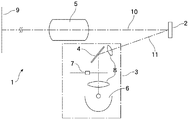
図1に、DMDをライトバルブとして採用したプロジェクタの概略構成を示してある。このプロジェクタ1は、光変調器(ライトバルブ)であるDMD2と、このDMD2に変調用の照明光11を照射するシステム3と、DMD2により有効な方向に反射された投影光10をスクリーン9に投写する投写用レンズシステム5とを備えている。図1に示したプロジェクタ1は、単板式のビデオプロジェクタであり、光照射システム3は、ハロゲンランプなどの白色光源6と、円盤型の回転色分割フィルタ7とを備えている。このため、DMD2には、赤、緑、青の3原色が時分割で照射される。そして、それぞれの色の光が照射されるタイミングで個々の画素に対応する素子を制御することによりカラー画像が表示される。光照射システム3は、さらに、光源6からの光を集光して非テレセントリックな照明光11を、ミラー4などを介してDMD2に出力する照明レンズシステム8を備えている。
FIG. 1 shows a schematic configuration of a projector that employs a DMD as a light valve. The
図2に、本発明に係る投写用レンズシステム5の一例を示してある。本例の投写用レンズシステム5は、スクリーン9の側から2つのレンズ群G1およびG2にグループ化された14枚のレンズL11〜L31により構成されている。それぞれのレンズの詳細なデータは以下に示した通りである。
FIG. 2 shows an example of the
スクリーン側の第1のレンズ群G1は全体が負の屈折力を備えたレンズ群であり、最もスクリーン側(前方)に位置し、スクリーン9の側に凸の負のメニスカスレンズL11およびL12と、両凹の負レンズL13とにより構成されている。最もスクリーン9の側のレンズL11はプラスチックレンズであり、その両面S1およびS2は非球面である。
The first lens group G1 on the screen side is a lens group having a negative refractive power as a whole, is located on the most screen side (front), and has negative meniscus lenses L11 and L12 that are convex on the
DMD2の側に位置する第2のレンズ群G2は、全体が正の屈折力を備えたレンズ群であり、両凸の正レンズL21およびスクリーン9の側に凹の負のメニスカスレンズL22からなる2枚貼合わせレンズD1と、スクリーン9の側に凸の負のメニスカスレンズL23および両凸の正レンズL24からなる2枚貼合わせレンズD2と、スクリーン9の側に凹の負のメニスカスレンズL25と、両凸の正レンズL26、両凹の負レンズL27および両凸の正レンズL28からなる3枚貼合わせレンズTLと、スクリーン9の側に凸の負のメニスカスレンズL29および両凸の正レンズL30からなる2枚貼合わせレンズD3と、両凸の正レンズL31とにより構成されている。
The second lens group G2 located on the DMD2 side is a lens group having a positive refractive power as a whole, and is composed of a biconvex positive lens L21 and a negative meniscus lens L22 concave on the
したがって、本例のレンズシステム5の第2のレンズ群G2は、3つの2枚貼合わせレンズ(バルサムレンズあるいはダブレット)D1、D2およびD3と、1つの3枚貼合わせレンズTLとを備えている。そして、スクリーン側の2枚貼合わせレンズD1およびD2により、接合面S8およびS11が逆方向を向いた屈折力が正の2枚貼合わせレンズのペアPLが構成されている。
Accordingly, the second lens group G2 of the
以下に示すレンズデータにおいて、riはスクリーン側から順番に並んだ各レンズの面S1〜S24の曲率半径(mm)、diはスクリーン側から順番に並んだ各レンズ面S1〜S24の間の距離(mm)、ndはスクリーン側から順番に並んだ各レンズの屈折率(d線)、νdはスクリーン側から順番に並んだ各レンズのアッベ数(d線)を示す。また、TypeのSPHは球面を示し、ASPは非球面を示す。 In the lens data shown below, ri is the radius of curvature (mm) of the lens surfaces S1 to S24 arranged in order from the screen side, and di is the distance between the lens surfaces S1 to S24 arranged in sequence from the screen side ( mm), nd represents the refractive index (d line) of each lens arranged in order from the screen side, and νd represents the Abbe number (d line) of each lens arranged in order from the screen side. Type SPH indicates a spherical surface, and ASP indicates an aspherical surface.
レンズデータ
No. ri Type di nd νd
1 281.95300 ASP 5.5000 1.52500 56.20 レンズL11
2 51.33900 ASP 9.3000
3 45.01100 SPH 2.6000 1.67000 47.20 レンズL12
4 16.60000 SPH 12.5000
5 -63.65800 SPH 2.1000 1.74300 49.40 レンズL13
6 22.83100 SPH 15.2000
7 41.78900 SPH 11.2000 1.67300 32.10 レンズL21(D1)
8 -22.79800 SPH 2.0000 1.84700 23.80 レンズL22
9 -41.29200 SPH 13.0000
10 64.54300 SPH 1.8000 1.77300 49.60 レンズL23(D2)
11 12.22400 SPH 7.5000 1.62000 36.30 レンズL24
12 -138.54600 SPH 3.0000
13 -24.63200 SPH 1.7000 1.84700 23.80 レンズL25
14 -72.50900 SPH 0.4000
15 20.67200 SPH 5.8000 1.62000 36.30 レンズL26(TL)
16 -20.67200 SPH 1.8000 1.83400 37.20 レンズL27
17 24.82500 SPH 4.9000 1.51600 64.10 レンズL28
18 -24.82500 SPH 0.3000
19 62.08500 SPH 1.7000 1.83400 37.20 レンズL29(D3)
20 15.18000 SPH 4.6000 1.48700 70.20 レンズL30
21 -57.34100 SPH 0.3000
22 52.39300 SPH 3.0000 1.48700 70.20 レンズL31
23 -52.39300 SPH 35.6600
Lens data No. ri Type di nd νd
1 281.95300 ASP 5.5000 1.52500 56.20 Lens L11
2 51.33900 ASP 9.3000
3 45.01100 SPH 2.6000 1.67000 47.20 Lens L12
4 16.60000 SPH 12.5000
5 -63.65800 SPH 2.1000 1.74300 49.40 Lens L13
6 22.83100 SPH 15.2000
7 41.78900 SPH 11.2000 1.67300 32.10 Lens L21 (D1)
8 -22.79800 SPH 2.0000 1.84700 23.80 Lens L22
9 -41.29200 SPH 13.0000
10 64.54300 SPH 1.8000 1.77300 49.60 Lens L23 (D2)
11 12.22400 SPH 7.5000 1.62000 36.30 Lens L24
12 -138.54600 SPH 3.0000
13 -24.63200 SPH 1.7000 1.84700 23.80 Lens L25
14 -72.50900 SPH 0.4000
15 20.67200 SPH 5.8000 1.62000 36.30 Lens L26 (TL)
16 -20.67200 SPH 1.8000 1.83400 37.20 Lens L27
17 24.82500 SPH 4.9000 1.51600 64.10 Lens L28
18 -24.82500 SPH 0.3000
19 62.08500 SPH 1.7000 1.83400 37.20 Lens L29 (D3)
20 15.18000 SPH 4.6000 1.48700 70.20 Lens L30
21 -57.34100 SPH 0.3000
22 52.39300 SPH 3.0000 1.48700 70.20 Lens L31
23 -52.39300 SPH 35.6600
最もスクリーン側のレンズL11の両面S1およびS2の非球面係数は以下の通りである。
面S1
R= 281.953、 K=0.0000
A= 1.3644×10⁻⁵、 B=−1.0494×10⁻⁸
C= 7.2586×10⁻¹²、 D=−2.0652×10⁻¹⁵
ただし、非球面は、Xを光軸方向の座標、Yを光軸と垂直方向の座標、光の進行方向を正とし、Rを近軸曲率半径とし、上記の係数K、A、B、C、Dを用いて次式で表される。以下においても同様である。
X=(1/R)Y2/[1+{1−(1+K)(1/R)2Y2}1/2]
+AY4+BY6+CY8+DY10
面S2
R= 51.339、 K=0.0000
A= 1.0026×10⁻⁵、 B=−2.3509×10⁻⁹
C=−1.2569×10⁻¹¹、 D= 6.7618×10⁻¹⁵
The aspherical coefficients of both surfaces S1 and S2 of the lens L11 on the most screen side are as follows.
Surface S1
R = 281.953, K = 0.0000
A = 1.3644 × 10 −5 , B = −1.0494 × 10 −8
C = 7.2586 × 10 −12 , D = −2.0652 × 10 −15
However, for an aspherical surface, X is the coordinate in the optical axis direction, Y is the coordinate perpendicular to the optical axis, the light traveling direction is positive, R is the paraxial radius of curvature, and the above coefficients K, A, B, C , D is represented by the following formula. The same applies to the following.
X = (1 / R) Y 2 / [1+ {1− (1 + K) (1 / R) 2 Y 2 } 1/2 ]
+ AY 4 + BY 6 + CY 8 + DY 10
Surface S2
R = 51.339, K = 0.0000
A = 1.0026 × 10 −5 , B = −2.3509 × 10 −9
C = −1.2569 × 10 −11 , D = 6.7618 × 10 −15
本例の投写レンズ5の諸数値は以下の通りである。
レンズL11の面S1からスクリーンまでの距離:1100mm
合成焦点距離: 10.1mm
半画角: 47.3度
バックフォーカス:35.66mm
レンズL11の焦点距離: 120.2mm
Various numerical values of the
Distance from surface S1 of lens L11 to the screen: 1100mm
Composite focal length: 10.1mm
Half angle of view: 47.3 degrees Back focus: 35.66 mm
Focal length of lens L11: 120.2mm
したがって、上述した条件(A)は以下のようになる。
|f11/fw|=0.084
Therefore, the condition (A) described above is as follows.
| F11 / fw | = 0.084
図3に、この投写用レンズシステム5の球面収差、非点収差および歪曲収差を示してある。球面収差は、670.0nm(短破線)、650.0nm(一点鎖線)、550.0nm(実線)、450.0nm(長破線)、440.0nm(二点鎖線)の各波長における値を示している。また、非点収差においては、サジタル光線(X)およびタンジェンシャル光線(Y)の収差を示してある。これらの図に示してあるように、本例の投写用レンズシステム5の縦収差はほぼ±0.1mm程度の範囲に入り、収差が非常に良好に補正されていることが分かる。
FIG. 3 shows the spherical aberration, astigmatism and distortion of the
図4に、本例の投写用レンズシステム5を通ってスクリーン9に投影される投影光10の一部を示してある。本例の投写用レンズ5は、負のパワーの第1のレンズ群G1と、正のパワーの第2のレンズ群G2が組み合わされたレトロフォーカス型のレンズであり、ライトバルブ2から投影光11が入射される側がライトバルブ2の側に主光線が広がる非テレセントリックになっている。さらに、第2のレンズ群G2のスクリーン9の側に、接合面S8およびS11が相互に逆方向を向いた、屈折力が正の2枚貼合わせレンズD1およびD2のペアPLが配置され、ライトバルブ2の側に、屈折力が正の3枚貼合わせレンズTLと、屈折力が正の2枚貼合わせレンズD3とが配置された構成になっている。これらの2枚貼合わせレンズD1、D2およびD3と、3枚貼合わせレンズTLとは、貼合わせレンズとしてのパワーは正なので、パワー配分としては、スクリーン9の側から、正−正−負−正−正−正の6枚のレンズ構成と同等である。したがって、これらの貼合わせレンズD1、D2、D3およびTLは、全体が正のパワーの第2のレンズ群G2に適合しており、第2のレンズ群G2の長さを延ばさずに、11枚と多数枚のレンズを配置することができる。
FIG. 4 shows a part of the
接合面S8およびS11が逆方向を向いた、2枚貼合わせレンズD1およびD2のペアPLは、色収差を補正するのに適していると共に、貼合わせレンズD1およびD2の内部に備えた逆方向を向いた面S8およびS11の曲率をある程度確保することによりペッツバール和を効果的に小さくしている。したがって、2枚貼合わせレンズD1およびD2のペアPLは像面湾曲の補正に適している。さらに、第1のレンズG1に対する入射光線が広がる第2のレンズ群G2のスクリーン9の側に配置することにより、これらのレンズD1およびD2の周辺部を用いて、軸外光線の色収差を効果的に補正できるようにしている。また、この貼合わせレンズD1およびD2のペアPLは、対称的なレンズ配置になるのでコマ収差などの他の諸収差の補正も良好に行うことができる。
The pair PL of the two-bonded lenses D1 and D2 with the cemented surfaces S8 and S11 facing in the reverse direction is suitable for correcting chromatic aberration and has the reverse direction provided inside the bonded lenses D1 and D2. The Petzval sum is effectively reduced by ensuring a certain degree of curvature of the facing surfaces S8 and S11. Therefore, the pair PL of the two laminated lenses D1 and D2 is suitable for correction of field curvature. Further, by disposing the second lens group G2 on the
3枚貼合わせレンズTLは、トリプレットを構成する正−負−正のレンズを貼り合わせた構成となっている。したがって、貼合わせレンズTLの内部には、逆方向を向いた曲率の大きな面S16およびS17を形成できるので、コンパクトなレンズでペッツバール和を効果的に小さくできる。さらに、入射側が非テレセントリックな投写レンズシステム5の入射側の光線が集中する箇所に3枚貼合わせレンズTLを配置することにより、3枚貼合わせレンズTLの径を小さくして、コストを下げることができる。光軸上に光線が集中する場所に配置することにより、内部の接合面S16およびS17の曲率を大きくすることがペッツバール和を小さくすることにいっそう効果的となり、像面湾曲をいっそう良好に補正できる。また、3枚貼合わせレンズTLは、対称的なレンズ配置になるのでコマ収差などの他の諸収差の補正も良好に行うことができる。さらに、3枚貼合わせレンズTLは、ゴーストの発生を防止でき、軸上および倍率色収差を効果的に補正できるという特性を備えている。
The three-piece bonded lens TL has a configuration in which positive-negative-positive lenses constituting a triplet are bonded together. Therefore, since the surfaces S16 and S17 having large curvatures facing in the opposite directions can be formed inside the bonded lens TL, the Petzval sum can be effectively reduced with a compact lens. Furthermore, the diameter of the three-piece laminated lens TL is reduced by reducing the cost by arranging the three-piece laminated lens TL at a position where the incident-side light rays of the
さらに、3枚貼合わせレンズTLのライトバルブ2の側に、2枚貼合わせレンズD3を配置している。3枚貼合わせレンズTLのライトバルブ2の側は、ライトバルブ2からの入射光、特に軸外光が光軸からまだ離れた状態にあり、2枚貼合わせレンズD3を配置することにより、入射側において色収差を含めて、他の収差を効果的に補正することができる。
Further, a two-sheet bonding lens D3 is disposed on the
このように、本例の投写用レンズシステム5では、入射側を非テレセントリックにすることにより第2のレンズ群G2の径を小さくすると共に、レンズシステム5の全長を短くし、さらに、第2のレンズ群G2に上記のように2枚貼合わせレンズおよび3枚貼合わせレンズを配置することによりその収差補正能力、特に像面湾曲の補正能力を大きくしている。したがって、コンパクトで、大きな画像を鮮明に投影できる、広角な投写用レンズシステムを提供することが可能となっており、本例では半画角が47度を超える性能が得られている。
Thus, in the
さらに、第2のレンズ群G2の像面湾曲などの収差の補正を高くすることにより、第1のレンズ群G1の収差補正の負荷を低減でき、第1のレンズ群G1のパワー、特に、大口径となる、最もスクリーン9の側のレンズL11のパワー配分を小さくできる。したがって、最もスクリーン側の第1のレンズL11を、プラスチックレンズを用いて低コストで製造でき、レンズシステム5の結像性能に対するレンズL11の温度変化による影響も低く抑えることができる。したがって、温度変化に対して安定した性能を備えた広角で、コンパクトなレンズシステムを提供できる。
Further, by increasing the correction of aberrations such as field curvature of the second lens group G2, it is possible to reduce the aberration correction load of the first lens group G1, and to reduce the power of the first lens group G1, in particular, large. The power distribution of the lens L11 closest to the
この投写レンズシステム5を用いたプロジェクタ1においては、スクリーン9の近くから大画像を投影することが可能であり、大画面を備えたコンパクトなプロジェクタを提供できる。特に、リア型のプロジェクタ1においては、ハウジング内に、照明系3、ライトバルブ2、投写レンズシステム5、スクリーン9が収納されるので、投写レンズシステム5からスクリーン9までの距離を小さくすることはプロジェクタ1を全体的にコンパクトにするのに効果的である。さらに、ハウジング内の温度が高くなっても、本例の投写レンズシステム5においては結像性能の低下はほとんどなく、スクリーンに高画質の大画像を安定して出力することができる。
In the
1 プロジェクタ
2 DMD(ライトバルブ、光変調装置)
3 光照射システム(照明系)
5 投写用レンズシステム
9 スクリーン
1
3 Light irradiation system (lighting system)
5
Claims (6)
前記スクリーンの側から順に、負の屈折力の第1のレンズ群と、正の屈折力の第2のレンズ群とで構成され、入射側が非テレセントリックであり、
前記第2のレンズ群は、接合面が逆方向を向いた屈折力が正の2枚貼合わせレンズのペアと、屈折力が正の3枚貼合わせレンズとを含んでおり、
前記第1のレンズ群の最も前記スクリーン側の第1のレンズは、負の非球面プラスチックレンズであり、その焦点距離f11と、当該投写用レンズシステムの合成焦点距離fwとが次の式を満たす投写用レンズシステム。
|f11/fw| <0.1 A projection lens system that projects projection light from a light modulator onto a screen,
In order from the screen side, the first lens group having a negative refractive power and the second lens group having a positive refractive power, and the incident side is non-telecentric,
The second lens group includes a pair of refractive power cemented surface facing backward positive two cemented lenses, refractive power includes a positive three cemented lenses,
The first lens on the most screen side of the first lens group is a negative aspheric plastic lens, and its focal length f11 and the combined focal length fw of the projection lens system satisfy the following expression. Projection lens system.
| F11 / fw | <0.1
Priority Applications (2)
| Application Number | Priority Date | Filing Date | Title |
|---|---|---|---|
| JP2005030608A JP4683944B2 (en) | 2005-02-07 | 2005-02-07 | Projection lens system and projector apparatus |
| US11/348,076 US7184219B2 (en) | 2005-02-07 | 2006-02-06 | Projection lens system and projector |
Applications Claiming Priority (1)
| Application Number | Priority Date | Filing Date | Title |
|---|---|---|---|
| JP2005030608A JP4683944B2 (en) | 2005-02-07 | 2005-02-07 | Projection lens system and projector apparatus |
Publications (3)
| Publication Number | Publication Date |
|---|---|
| JP2006215476A JP2006215476A (en) | 2006-08-17 |
| JP2006215476A5 JP2006215476A5 (en) | 2008-03-27 |
| JP4683944B2 true JP4683944B2 (en) | 2011-05-18 |
Family
ID=36779645
Family Applications (1)
| Application Number | Title | Priority Date | Filing Date |
|---|---|---|---|
| JP2005030608A Expired - Fee Related JP4683944B2 (en) | 2005-02-07 | 2005-02-07 | Projection lens system and projector apparatus |
Country Status (2)
| Country | Link |
|---|---|
| US (1) | US7184219B2 (en) |
| JP (1) | JP4683944B2 (en) |
Cited By (2)
| Publication number | Priority date | Publication date | Assignee | Title |
|---|---|---|---|---|
| US9069154B2 (en) | 2013-04-12 | 2015-06-30 | Fujifilm Corporation | Projection lens and projection type display device |
| CN107678147A (en) * | 2017-09-19 | 2018-02-09 | 浙江大华技术股份有限公司 | A kind of lens combination, fish eye lens and image collecting device |
Families Citing this family (19)
| Publication number | Priority date | Publication date | Assignee | Title |
|---|---|---|---|---|
| JPWO2005111688A1 (en) * | 2004-05-17 | 2008-03-27 | 松下電器産業株式会社 | Projection lens and rear projection type projection apparatus |
| WO2008029657A1 (en) * | 2006-09-04 | 2008-03-13 | Brother Kogyo Kabushiki Kaisha | Image projecting device, and projection lens |
| US7952817B2 (en) * | 2008-08-08 | 2011-05-31 | Young Optics Inc. | Projection lens |
| TWI410671B (en) * | 2008-08-08 | 2013-10-01 | Young Optics Inc | Projection lens |
| JP5189451B2 (en) * | 2008-09-30 | 2013-04-24 | リコー光学株式会社 | Projection lens and projection-type image display device |
| US7988306B2 (en) * | 2008-10-02 | 2011-08-02 | Eastman Kodak Company | Afocal attachment for projection lens |
| US7944623B2 (en) * | 2008-12-24 | 2011-05-17 | Young Optics Inc. | Fixed-focus lens |
| JP2010186011A (en) * | 2009-02-12 | 2010-08-26 | Olympus Imaging Corp | Wide angle optical system and image pickup apparatus using the same |
| TW201037354A (en) * | 2009-04-15 | 2010-10-16 | Young Optics Inc | Fixed-focus lens |
| TWI395046B (en) * | 2009-04-24 | 2013-05-01 | Asia Optical Co Inc | Zoom projection lens |
| JP5275902B2 (en) * | 2009-05-25 | 2013-08-28 | 富士フイルム株式会社 | Wide angle lens for projection and projection display device |
| TWI439722B (en) | 2012-07-27 | 2014-06-01 | Young Optics Inc | Fixed-focus lens |
| JP2014206612A (en) | 2013-04-12 | 2014-10-30 | 富士フイルム株式会社 | Projection lens and projection type display device |
| JP2015143861A (en) * | 2015-02-12 | 2015-08-06 | 株式会社リコー | Projection optical system and image display device |
| JP6309478B2 (en) * | 2015-03-31 | 2018-04-11 | 富士フイルム株式会社 | Imaging lens and imaging apparatus |
| US10571669B2 (en) | 2015-12-28 | 2020-02-25 | Young Optics Inc. | Optical lens |
| US10185129B2 (en) | 2017-03-22 | 2019-01-22 | Young Optics Inc. | Optical lens |
| CN114924380B (en) * | 2022-04-29 | 2023-08-04 | 歌尔光学科技有限公司 | Optical projection system and electronic equipment |
| CN114859524B (en) * | 2022-07-07 | 2022-10-25 | 沂普光电(天津)有限公司 | Ultra-short-focus optical system and projection equipment |
Citations (2)
| Publication number | Priority date | Publication date | Assignee | Title |
|---|---|---|---|---|
| JP2002365541A (en) * | 2001-06-05 | 2002-12-18 | Chinontec Kk | Projection lens device and projector device |
| JP2004233609A (en) * | 2003-01-30 | 2004-08-19 | Nitto Kogaku Kk | Projection lens system and projector |
Family Cites Families (4)
| Publication number | Priority date | Publication date | Assignee | Title |
|---|---|---|---|---|
| US2660094A (en) * | 1951-07-16 | 1953-11-24 | Taylor Taylor & Hobson Ltd | Two member optical objective |
| JP2000338448A (en) | 1999-05-31 | 2000-12-08 | Minolta Co Ltd | Projection type picture display device |
| JP4450296B2 (en) * | 1999-12-10 | 2010-04-14 | フジノン株式会社 | Projection lens and projection projector apparatus |
| KR100410964B1 (en) * | 2001-07-27 | 2003-12-18 | 삼성전기주식회사 | Projection lens of projection display apparatus |
-
2005
- 2005-02-07 JP JP2005030608A patent/JP4683944B2/en not_active Expired - Fee Related
-
2006
- 2006-02-06 US US11/348,076 patent/US7184219B2/en not_active Expired - Fee Related
Patent Citations (2)
| Publication number | Priority date | Publication date | Assignee | Title |
|---|---|---|---|---|
| JP2002365541A (en) * | 2001-06-05 | 2002-12-18 | Chinontec Kk | Projection lens device and projector device |
| JP2004233609A (en) * | 2003-01-30 | 2004-08-19 | Nitto Kogaku Kk | Projection lens system and projector |
Cited By (2)
| Publication number | Priority date | Publication date | Assignee | Title |
|---|---|---|---|---|
| US9069154B2 (en) | 2013-04-12 | 2015-06-30 | Fujifilm Corporation | Projection lens and projection type display device |
| CN107678147A (en) * | 2017-09-19 | 2018-02-09 | 浙江大华技术股份有限公司 | A kind of lens combination, fish eye lens and image collecting device |
Also Published As
| Publication number | Publication date |
|---|---|
| JP2006215476A (en) | 2006-08-17 |
| US7184219B2 (en) | 2007-02-27 |
| US20060176577A1 (en) | 2006-08-10 |
Similar Documents
| Publication | Publication Date | Title |
|---|---|---|
| JP4683944B2 (en) | Projection lens system and projector apparatus | |
| JP6530796B2 (en) | Projection optical system | |
| JP4920761B2 (en) | Projection zoom lens and projector apparatus | |
| JP5287326B2 (en) | Projection zoom lens and projection-type image display device | |
| JP5766889B2 (en) | Projection zoom lens and projection display device | |
| JP5253126B2 (en) | Lens system and display device | |
| US7184220B2 (en) | Projection zoom lens and projector | |
| JP4222408B2 (en) | Zoom lens and projector | |
| JP2007304290A (en) | Zoom lens for projection and projection type display device | |
| JP2010113150A (en) | Projection zoom lens and projection type display apparatus | |
| JP5118583B2 (en) | Projection lens and projection display device using the same | |
| JPH10232349A (en) | Focal length variable type lens device | |
| JP2005331649A (en) | Lens system for projection and projector apparatus | |
| JP2019015829A (en) | Optical system and image projection device | |
| JP2008309991A (en) | Projection lens and projection display apparatus using the same | |
| JP4851146B2 (en) | Two-group zoom projection lens and projection display device | |
| JP5397562B2 (en) | Projection zoom lens and projection-type image display device | |
| JP6167649B2 (en) | Projection zoom lens and image display device | |
| JP2004309865A (en) | Projection lens | |
| JP2011154193A (en) | Projection lens and projection type display device using the same | |
| JP6303376B2 (en) | Projection zoom lens and image display device | |
| JP2009222982A (en) | Zoom lens and projector | |
| JP4164283B2 (en) | Projection lens system and projector apparatus | |
| JP2013195636A (en) | Projection optical system and projection-type display device | |
| JP6244795B2 (en) | Projection zoom lens |
Legal Events
| Date | Code | Title | Description |
|---|---|---|---|
| A521 | Request for written amendment filed |
Free format text: JAPANESE INTERMEDIATE CODE: A523 Effective date: 20080207 |
|
| A621 | Written request for application examination |
Free format text: JAPANESE INTERMEDIATE CODE: A621 Effective date: 20080207 |
|
| A131 | Notification of reasons for refusal |
Free format text: JAPANESE INTERMEDIATE CODE: A131 Effective date: 20101116 |
|
| A521 | Request for written amendment filed |
Free format text: JAPANESE INTERMEDIATE CODE: A523 Effective date: 20110112 |
|
| TRDD | Decision of grant or rejection written | ||
| A01 | Written decision to grant a patent or to grant a registration (utility model) |
Free format text: JAPANESE INTERMEDIATE CODE: A01 Effective date: 20110128 |
|
| A01 | Written decision to grant a patent or to grant a registration (utility model) |
Free format text: JAPANESE INTERMEDIATE CODE: A01 |
|
| A61 | First payment of annual fees (during grant procedure) |
Free format text: JAPANESE INTERMEDIATE CODE: A61 Effective date: 20110208 |
|
| FPAY | Renewal fee payment (event date is renewal date of database) |
Free format text: PAYMENT UNTIL: 20140218 Year of fee payment: 3 |
|
| R150 | Certificate of patent or registration of utility model |
Ref document number: 4683944 Country of ref document: JP Free format text: JAPANESE INTERMEDIATE CODE: R150 Free format text: JAPANESE INTERMEDIATE CODE: R150 |
|
| R250 | Receipt of annual fees |
Free format text: JAPANESE INTERMEDIATE CODE: R250 |
|
| R250 | Receipt of annual fees |
Free format text: JAPANESE INTERMEDIATE CODE: R250 |
|
| S533 | Written request for registration of change of name |
Free format text: JAPANESE INTERMEDIATE CODE: R313533 |
|
| R350 | Written notification of registration of transfer |
Free format text: JAPANESE INTERMEDIATE CODE: R350 |
|
| R250 | Receipt of annual fees |
Free format text: JAPANESE INTERMEDIATE CODE: R250 |
|
| R250 | Receipt of annual fees |
Free format text: JAPANESE INTERMEDIATE CODE: R250 |
|
| R250 | Receipt of annual fees |
Free format text: JAPANESE INTERMEDIATE CODE: R250 |
|
| LAPS | Cancellation because of no payment of annual fees |