JP4657807B2 - PHYSICAL QUANTITY DETECTION DEVICE HAVING BRIDGE CIRCUIT AND ZERO POINT ADJUSTMENT METHOD - Google Patents
PHYSICAL QUANTITY DETECTION DEVICE HAVING BRIDGE CIRCUIT AND ZERO POINT ADJUSTMENT METHOD Download PDFInfo
- Publication number
- JP4657807B2 JP4657807B2 JP2005150897A JP2005150897A JP4657807B2 JP 4657807 B2 JP4657807 B2 JP 4657807B2 JP 2005150897 A JP2005150897 A JP 2005150897A JP 2005150897 A JP2005150897 A JP 2005150897A JP 4657807 B2 JP4657807 B2 JP 4657807B2
- Authority
- JP
- Japan
- Prior art keywords
- physical quantity
- circuit
- bridge
- sensor element
- output
- Prior art date
- Legal status (The legal status is an assumption and is not a legal conclusion. Google has not performed a legal analysis and makes no representation as to the accuracy of the status listed.)
- Expired - Fee Related
Links
Images


Description
本発明は、ブリッジ回路を備えた物理量検出装置に関し、特に、測定対象となる物理量に応じてインピーダンスが変化する一対のセンサ素子を備えた検出装置に関している。本明細書における「物理量」とは、使用するセンサ素子で測定可能な物理量であって、力(トルク荷重を含む種々の力)、電流、電圧、光量、温度などを広く含むものとする。 The present invention relates to a physical quantity detection device including a bridge circuit, and more particularly, to a detection device including a pair of sensor elements whose impedance changes according to a physical quantity to be measured. The “physical quantity” in this specification is a physical quantity that can be measured by the sensor element to be used, and widely includes force (various forces including torque load), current, voltage, light quantity, temperature, and the like.
従来より、磁歪センサ素子を備えた磁歪式荷重検出装置が開発されている。磁歪センサ素子は、荷重に応じて初透磁率が変化する磁歪材料を用い、磁歪材料の初透磁率の変化を検出用コイルなどのインピーダンス(インダクタンスおよび抵抗値)の変化として検出する素子である。磁歪材料としては、例えば鉄系、鉄クロム系、鉄ニッケル系、鉄コバルト系、純鉄、鉄珪素系、鉄アルミニウム系、パーマロイ系などの磁性材料、軟磁性材料、または超磁性材料などが好適に用いられる。 Conventionally, a magnetostrictive load detecting device including a magnetostrictive sensor element has been developed. The magnetostrictive sensor element is an element that uses a magnetostrictive material whose initial permeability changes according to a load, and detects a change in the initial permeability of the magnetostrictive material as a change in impedance (inductance and resistance value) of a detection coil or the like. As the magnetostrictive material, for example, iron-based, iron-chromium-based, iron-nickel-based, iron-cobalt-based, pure iron, iron-silicon-based, iron-aluminum-based, permalloy-based magnetic materials, soft magnetic materials, or supermagnetic materials are suitable. Used for.
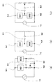
図1(a)は、従来の磁歪式荷重検出装置における典型的な検知回路を示す等価回路図である。この図に示されるブリッジ回路は、交流電圧(交流電流)が入力される第1および第2の入力点N1、N2と、不図示の差動増幅回路に接続される第1および第2の出力点S1、S2を有しており、第1および第2の入力点N1、N2に入力される交流電圧は、交流電圧生成回路部10から供給される。
FIG. 1A is an equivalent circuit diagram showing a typical detection circuit in a conventional magnetostrictive load detection device. The bridge circuit shown in this figure includes first and second input points N1 and N2 to which an alternating voltage (alternating current) is input, and first and second outputs connected to a differential amplifier circuit (not shown). The AC voltage having points S1 and S2 is supplied from the AC voltage
図1(a)のブリッジ回路では、磁歪センサ素子SE1、SE2が並列に接続されている。このようなブリッジ回路を「並列型ブリッジ回路」と称することとする。並列型ブリッジ回路を備えた荷重検出装置は、例えば特許文献1〜4に記載されている。
In the bridge circuit of FIG. 1A, magnetostrictive sensor elements SE1 and SE2 are connected in parallel. Such a bridge circuit is referred to as a “parallel bridge circuit”. For example,
並列型ブリッジ回路において、一対の磁歪センサ素子の間に初透磁率のばらつきが存在すると、無荷重時平衡点および荷重時の出力感度が安定しないため、検出値の精度や信頼性が低下するという問題がある。このため、磁歪式センサ素子間に存在する初透磁率のばらつきによる影響を低減することが必要になる。 In a parallel bridge circuit, if there is a variation in initial permeability between a pair of magnetostrictive sensor elements, the equilibrium point at no load and the output sensitivity at load will not be stable, so the accuracy and reliability of the detection value will be reduced. There's a problem. For this reason, it is necessary to reduce the influence of variations in the initial permeability existing between the magnetostrictive sensor elements.
このような初透磁率のばらつきの影響を低減する最も効果的な方法は、ブリッジ回路を流れる交流電流(励磁電流)を増大させることにある。
しかしながら、従来の並列型ブリッジ回路を採用した場合、以下に述べる理由により、磁歪センサ素子の特性ばらつきを低減する目的で励磁電流をさらに増加させることは極めて難しい。 However, when the conventional parallel bridge circuit is employed, it is extremely difficult to further increase the excitation current for the purpose of reducing the characteristic variation of the magnetostrictive sensor element for the following reason.
図1(a)に示す並列型ブリッジ回路では、測定可能な荷重の範囲(検出レンジ)を拡大するためには、ブリッジ回路における固定抵抗の大きさを、磁歪センサ素子SE1、SE2の抵抗値(インピーダンス)と略同じ値に設定する必要がある。通常の磁歪センサ素子におけるインピーダンスは100Ω程度以下であるため、ブリッジ抵抗の大きさも100Ω程度に設定される。このため、ブリッジ回路のインピーダンスを更に大きくすることは困難である。 In the parallel bridge circuit shown in FIG. 1A, in order to expand the measurable load range (detection range), the magnitude of the fixed resistance in the bridge circuit is set to the resistance value of the magnetostrictive sensor elements SE1 and SE2. It is necessary to set to approximately the same value as (impedance). Since the impedance of a normal magnetostrictive sensor element is about 100Ω or less, the magnitude of the bridge resistance is also set to about 100Ω. For this reason, it is difficult to further increase the impedance of the bridge circuit.
一方、並列型ブリッジ回路で生じるインピーダンスの変化の影響が交流電圧生成回路部10の発振回路(不図示)に及ぶと、発振回路から出力される交流信号の発振波形が変化してしまうことになる。このような問題が生じないようにするには、発振回路と並列型ブリッジとの間にオペアンプなどを挿入し、バッファアンプとして機能させる必要がある。このような回路構成を採用すると、発振回路から出力された交流電圧は、オペアンプを介してから並列型ブリッジ回路に入力されるため、並列型ブリッジ回路におけるインピーダンスの変化は発振回路に影響しなくなる。しかし、オペアンプの性能上の制約から、並列型ブリッジ回路に供給することが可能な励磁電流の大きさは、せいぜい数10mA(ミリアンペア)程度になる。しかも、並列型ブリッジ回路には、対称に電流が流れるため、各磁歪センサ素子SE1、SE2に流れる励磁電流の大きさは、入力点N1、N2に供給される励磁電流の半分に低下してしまう。
On the other hand, when the influence of the impedance change generated in the parallel bridge circuit reaches the oscillation circuit (not shown) of the AC voltage
以上の理由から、各磁歪センサ素子SE1、SE2に流れる励磁電流の大きさを増加させることにより、センサ素子特性のばらつきに起因する影響を大幅に減少させることは極めて困難である。 For the above reasons, it is extremely difficult to significantly reduce the influence caused by variations in sensor element characteristics by increasing the magnitude of the excitation current flowing through each of the magnetostrictive sensor elements SE1 and SE2.
また、磁歪センサ素子のインピーダンスが極端に低い場合、ブリッジ回路とオペアンプとの間に抵抗器を挿入し、オペアンプが出力飽和を起こさないように電流制限を行なう必要がある。その結果、ブリッジ回路に印加される電圧が更に低下し、荷重の検出レンジが狭くなるという問題が生じる。 Further, when the impedance of the magnetostrictive sensor element is extremely low, it is necessary to insert a resistor between the bridge circuit and the operational amplifier to limit the current so that the operational amplifier does not cause output saturation. As a result, there is a problem that the voltage applied to the bridge circuit is further reduced and the load detection range is narrowed.
一方、磁歪センサ素子を用いてブリッジ回路を構成する場合、磁歪センサ素子が有する初透磁率ばらつきを補償するため、ゼロ点調整が必要となるが、実開7−2943号公報に開示されている並列型ブリッジ回路では、各磁歪センサに直列に接続された可変抵抗器の抵抗値を調節することにより、ゼロ点調整が行われる。しかし、以下に説明するように、このようなゼロ点調整では完全平衡状態を実現することはできない。 On the other hand, when a bridge circuit is configured using a magnetostrictive sensor element, a zero point adjustment is required to compensate for the initial permeability variation of the magnetostrictive sensor element, but this is disclosed in Japanese Utility Model Application Publication No. 7-2943. In the parallel bridge circuit, the zero point adjustment is performed by adjusting the resistance value of the variable resistor connected in series to each magnetostrictive sensor. However, as will be described below, such a zero point adjustment cannot achieve a perfect equilibrium state.
磁歪センサ素子は、交流電流により励磁されるため、完全に平衡調整を行う為には実数部と虚数部の両方のインピーダンス・アンバランスをゼロにする必要がある。しかしながら、従来のゼロ点調整方法では、インピーダンスのアンバランスのうち、実部または虚部のどちらか一方しか除去することができない。したがって、無荷重時における出力電圧をできる限り小さくするようにゼロ点調節を実行しても、残差電圧が必ず発生してしまう。残差電圧が発生すると、2つの磁歪センサ素子の出力特性に差が生じることになる。また、無荷重時における出力電圧がゼロでないため、出力電圧のダイナミック・レンジが狭まってしまうという欠点もある。このように、従来のブリッジ回路では、完全平衡調整を実現することができないため、測定精度が不十分であった。 Since the magnetostrictive sensor element is excited by an alternating current, impedance imbalance in both the real part and the imaginary part needs to be zero in order to achieve complete balance adjustment. However, in the conventional zero point adjustment method, only one of the real part and the imaginary part can be removed from the impedance imbalance. Therefore, even if the zero point adjustment is performed so that the output voltage under no load is as small as possible, a residual voltage is always generated. When the residual voltage is generated, a difference occurs between the output characteristics of the two magnetostrictive sensor elements. In addition, since the output voltage at no load is not zero, the dynamic range of the output voltage is reduced. As described above, the conventional bridge circuit cannot achieve perfect balance adjustment, so that the measurement accuracy is insufficient.
本発明は、上記課題を解決するためになされたものであり、その目的は、交流ブリッジ回路を備えた物理量検出装置において、1対のセンサ素子における出力特性ばらつきの影響を低減することにある。 The present invention has been made to solve the above-described problems, and an object of the present invention is to reduce the influence of variations in output characteristics of a pair of sensor elements in a physical quantity detection device including an AC bridge circuit.
また、本発明の他の目的は、ブリッジ回路における完全平衡調整を実現し、さらには完全平衡点の経時変化を抑制した物理量検出装置を提供することにある。 Another object of the present invention is to provide a physical quantity detection device that realizes complete balance adjustment in a bridge circuit and further suppresses a change with time of the complete balance point.
本発明の物理量検出装置は、交流電圧が供給される第1および第2の入力点と、差動増幅回路に接続される第1および第2の出力点とを有するブリッジ回路を備えた物理量検出装置であって、前記ブリッジ回路は、前記第1の入力点と前記第1の出力点とを電気的に接続する第1ブリッジアーム、前記第1の出力点と前記第2の入力点とを電気的に接続する第2ブリッジアーム、前記第1の入力点と前記第2の出力点とを電気的に接続する第3ブリッジアーム、および、前記第2の出力点と前記第2の入力点とを電気的に接続する第4ブリッジアームを有し、前記第1ブリッジアームは、測定対象となる物理量に応じてインピーダンスが変化する第1のセンサ素子を含み、かつ、前記第2ブリッジアームは、前記物理量に応じてインピーダンスが変化する第2のセンサ素子を含み、前記第1および第2ブリッジアームが有する合計のインピーダンスは、前記第3および第4のブリッジアームが有する合計のインピーダンスよりも小さく設定されている。 A physical quantity detection device according to the present invention includes a bridge circuit having first and second input points to which an AC voltage is supplied and first and second output points connected to a differential amplifier circuit. The bridge circuit includes a first bridge arm that electrically connects the first input point and the first output point, and the first output point and the second input point. A second bridge arm that is electrically connected, a third bridge arm that is electrically connected to the first input point and the second output point, and a second output point and the second input point The first bridge arm includes a first sensor element whose impedance changes in accordance with a physical quantity to be measured, and the second bridge arm Impedance depending on the physical quantity There includes a second sensor element which changes the impedance of the total with the first and second bridge arms is set to be smaller than the sum of the impedance of the third and fourth bridge arm has.
好ましい実施形態において、前記第1および第2のセンサ素子は、いずれも、荷重に応じてインピーダンスが変化する磁歪センサ素子であり、測定対象となる物理量は、前記第1および第2のセンサ素子のいずれか一方に加えられた荷重である。 In a preferred embodiment, each of the first and second sensor elements is a magnetostrictive sensor element whose impedance changes in accordance with a load, and a physical quantity to be measured is a value of the first and second sensor elements. It is the load applied to either one.
好ましい実施形態において、前記第1のセンサ素子は、磁歪材料から形成された第1磁歪部材と、前記第1磁歪部材を取り囲む第1コイルを有する第1の磁歪センサ素子であり、前記第1コイルは、前記第1の入力点と前記第1の出力点とを電気的に接続しており、前記第2のセンサ素子は、磁歪材料から形成された第2磁歪部材と、前記第2磁歪部材を取り囲む第2コイルを有する第2の磁歪センサ素子であり、前記第2コイルは、前記第1の出力点と前記第2の入力点とを電気的に接続している。 In a preferred embodiment, the first sensor element is a first magnetostrictive sensor element having a first magnetostrictive member formed of a magnetostrictive material and a first coil surrounding the first magnetostrictive member, and the first coil. Electrically connects the first input point and the first output point, and the second sensor element includes a second magnetostrictive member formed of a magnetostrictive material, and the second magnetostrictive member. The second magnetostrictive sensor element has a second coil surrounding the first coil, and the second coil electrically connects the first output point and the second input point.
好ましい実施形態において、前記第1および第2ブリッジアームが有する合計のインピーダンスは、前記第3および第4のブリッジアームが有する合計のインピーダンスの90%以下である。 In a preferred embodiment, the total impedance of the first and second bridge arms is 90% or less of the total impedance of the third and fourth bridge arms.
好ましい実施形態において、前記第1および第2ブリッジアームの少なくとも一方は、平衡調節用可変抵抗を含んでいる。 In a preferred embodiment, at least one of the first and second bridge arms includes a balance adjusting variable resistor.
好ましい実施形態において、前記ブリッジ回路は、前記第1のセンサ素子と前記第2のセンサ素子との間に直列的に接続された平衡調節用可変抵抗素子を有しており、前記第1の出力点は、前記平衡調節用可変抵抗素子に接続されている。 In a preferred embodiment, the bridge circuit includes a balancing variable resistance element connected in series between the first sensor element and the second sensor element, and the first output The point is connected to the balance adjusting variable resistance element.
好ましい実施形態において、前記ブリッジ回路は、前記第3のブリッジアームと前記第4のブリッジアームセンサ素子との間に直列的に接続された第2の平衡調節用可変抵抗素子を有しており、前記第2の出力点は、前記第2の平衡調節用可変抵抗素子に接続されている。 In a preferred embodiment, the bridge circuit includes a second variable resistance element for balance adjustment connected in series between the third bridge arm and the fourth bridge arm sensor element. The second output point is connected to the second variable resistance element for balance adjustment.
好ましい実施形態において、測定動作時において、前記第1の出力点と前記差動増幅回路との間、および、前記第2の出力点と前記差動増幅回路との間には電流が実質的に流れない。 In a preferred embodiment, during the measurement operation, current is substantially between the first output point and the differential amplifier circuit and between the second output point and the differential amplifier circuit. Not flowing.
好ましい実施形態において、前記ブリッジ回路における前記第1および第2の入力点に印加する交流電圧を生成する交流電圧生成回路と、前記第1および第2の出力点に接続される前記差動増幅回路とは同一電子回路基板上に搭載されている。 In a preferred embodiment, an AC voltage generation circuit that generates an AC voltage applied to the first and second input points in the bridge circuit, and the differential amplifier circuit connected to the first and second output points Are mounted on the same electronic circuit board.
好ましい実施形態において、前記交流電圧生成回路は、発振回路と、前記発振回路から出力される信号の振幅を制限する振幅制限回路とを有している。 In a preferred embodiment, the AC voltage generation circuit includes an oscillation circuit and an amplitude limiting circuit that limits the amplitude of a signal output from the oscillation circuit.
好ましい実施形態において、前記差動増幅回路を含む検出回路部を備え、前記検出回路部は、前記第1のセンサ素子によって測定される前記物理量の値と、前記第2のセンサ素子によって測定される前記物理量の値とが等しいときであっても、ゼロではない値を示す信号を出力することにより、前記検出回路部の出力信号を伝播する配線が断線しているか否かの判断が可能である。 In a preferred embodiment, a detection circuit unit including the differential amplifier circuit is provided, and the detection circuit unit is measured by the value of the physical quantity measured by the first sensor element and the second sensor element. Even when the value of the physical quantity is equal, it is possible to determine whether or not the wiring that propagates the output signal of the detection circuit unit is disconnected by outputting a signal indicating a non-zero value. .
本発明の乗り物は、上記いずれかの物理量検出装置と、前記物理量検出装置によって検出される物理量に応じて動作が制御されるエンジンとを備えている。 The vehicle of the present invention includes any one of the physical quantity detection devices described above and an engine whose operation is controlled according to the physical quantity detected by the physical quantity detection device.
好ましい実施形態において、前記物理量検出装置によって検出される物理量は、操作者によって前記乗り物のハンドルに加えられた力に依存した量である。 In a preferred embodiment, the physical quantity detected by the physical quantity detection device is an amount dependent on the force applied to the vehicle handle by the operator.
本発明のゼロ点調整方法は、上記の物理量検出装置におけるブリッジ回路のゼロ点調整方法であって、前記第1および第2のセンサ素子によって検知すべき物理量をゼロに設定した状態で前記平衡調整用可変抵抗器のいずれか一方を調節することにより、前記第1および第2の出力点の間における差動電圧の振幅を最小にする第1調整工程と、前記第1および第2のセンサ素子に与える物理量をゼロにした状態で前記平衡調整用可変抵抗器の他方を調節することにより、前記第1および第2の出力点の間における差動電圧の振幅を最小にする第2調整工程とを含む。 The zero point adjustment method of the present invention is a zero point adjustment method for a bridge circuit in the physical quantity detection device described above, wherein the balance adjustment is performed with the physical quantity to be detected by the first and second sensor elements set to zero. A first adjustment step of minimizing the amplitude of the differential voltage between the first and second output points by adjusting one of the variable resistors for use, and the first and second sensor elements A second adjustment step of minimizing the amplitude of the differential voltage between the first and second output points by adjusting the other of the balance adjustment variable resistors in a state in which the physical quantity applied to is zero. including.
好ましい実施形態において、前記第1調整工程および第2調整工程を繰り返すことにより前記差動電圧を極小化する。 In a preferred embodiment, the differential voltage is minimized by repeating the first adjustment step and the second adjustment step.
本発明によれば、ブリッジ回路における2つの電流径路のうちの一方においてセンサ素子を直列的に配列し、かつ、センサ素子に流れる励磁電流を増やすことにより、センサ素子の有する特性ばらつきの影響を低減することができる。また、本発明によれば、ゼロ点の完全平衡調整を実現することができるため、並列型ブリッジ回路を採用した従来例に比べ、2つのセンサ素子の間に生じ得る出力特性の差異を格段に縮小することも可能になる。 According to the present invention, the sensor elements are arranged in series in one of the two current paths in the bridge circuit, and the excitation current flowing through the sensor elements is increased, thereby reducing the influence of characteristic variations of the sensor elements. can do. Further, according to the present invention, zero point perfect balance adjustment can be realized, so that the difference in output characteristics that can occur between two sensor elements is markedly greater than the conventional example employing a parallel bridge circuit. It can also be reduced.
本発明の物理量検出装置は、物理量検出のためのセンサ素子が直列的に接続されたブリッジ回路を備えている。このブリッジ回路は、図1(b)に示すように、交流電圧が供給される第1および第2の入力点N1、N2と、差動増幅回路に接続される第1および第2の出力点S1、S2を有しており、第1および第2の入力点N1、N2に供給される交流電圧は、交流電圧生成回路部10から供給される。第1および第2の出力点S1、S2に接続される差動増幅回路(図1において不図示)の出力は、不図示の検出回路部から信号電圧として出力される。
The physical quantity detection device of the present invention includes a bridge circuit in which sensor elements for physical quantity detection are connected in series. As shown in FIG. 1B, the bridge circuit includes first and second input points N1 and N2 to which an AC voltage is supplied, and first and second output points connected to a differential amplifier circuit. The AC voltage supplied to the first and second input points N1 and N2 is supplied from the AC voltage
図1(b)に示されるブリッジ回路は、第1の入力点N1と第1の出力点S1とを電気的に接続する第1ブリッジアーム、第1の出力点S1と第2の入力点N2とを電気的に接続する第2ブリッジアーム、第1の入力点N1と第2の出力点S2とを電気的に接続する第3ブリッジアーム、および、第2の出力点S2と第2の入力点N2とを電気的に接続する第4ブリッジアームを有している。 The bridge circuit shown in FIG. 1B includes a first bridge arm that electrically connects the first input point N1 and the first output point S1, and the first output point S1 and the second input point N2. A second bridge arm that electrically connects the first input point N1 and the second output point S2, and a second bridge arm that electrically connects the second output point S2 and the second input. A fourth bridge arm that electrically connects the point N2 is provided.
第1ブリッジアームは、測定対象となる物理量に応じてインピーダンスが変化する第1のセンサ素子SE1を含み、かつ、第2ブリッジアームは、物理量に応じてインピーダンスが変化する第2のセンサ素子SE2を含む。このように、図1(b)に示すブリッジ回路では、2つのセンサ素子SE1、SE2が直列に接続されているため、このようなブリッジ回路を、従来の「並列型ブリッジ回路」に対して、「直列型ブリッジ回路」と称することができる。 The first bridge arm includes a first sensor element SE1 whose impedance changes according to the physical quantity to be measured, and the second bridge arm includes a second sensor element SE2 whose impedance changes according to the physical quantity. Including. As described above, in the bridge circuit shown in FIG. 1B, the two sensor elements SE1 and SE2 are connected in series. Therefore, such a bridge circuit is compared with the conventional “parallel bridge circuit”. It can be referred to as a “series bridge circuit”.
本発明では、センサ素子SE1、SE2が直列に接続されている第1および第2ブリッジアームが有する合計のインピーダンスを、第3および第4のブリッジアームが有する合計のインピーダンス(固定抵抗値)よりも小さく設定している。このため、第1および第2の入力点N1、N2の間に交流電流を流すとき、第3および第4のブリッジアームを流れる電流に比べ、第1および第2ブリッジアームを流れる電流が大きくなる。その結果、直列接続された2つのセンサ素子SE1、SE2を流れる電流を並列型に比べて格段に大きくことができるため、センサ素子SE1、SE2の特性ばらつきに起因する影響を低減することができる。より具体的には、第1および第2ブリッジアームの合計インピーダンスを、第3および第4ブリッジアームの合計インピーダンスの1/9の大きさに設定した場合、交流電圧生成回路部10からブリッジ回路部20に供給される交流電流の90%が第1および第2ブリッジアームを流れることになる。
In the present invention, the total impedance of the first and second bridge arms to which the sensor elements SE1 and SE2 are connected in series is greater than the total impedance (fixed resistance value) of the third and fourth bridge arms. It is set small. For this reason, when an alternating current flows between the first and second input points N1 and N2, the current flowing through the first and second bridge arms becomes larger than the current flowing through the third and fourth bridge arms. . As a result, the current flowing through the two sensor elements SE1 and SE2 connected in series can be remarkably increased as compared with the parallel type, so that the influence due to the characteristic variation of the sensor elements SE1 and SE2 can be reduced. More specifically, when the total impedance of the first and second bridge arms is set to 1/9 of the total impedance of the third and fourth bridge arms, the AC voltage
第1および第2ブリッジアームが有する合計のインピーダンスは、第3および第4のブリッジアームが有する合計のインピーダンスの90%以下であることが好ましく、50%以下であることがさらに好ましく、20%以下であることが最も好ましい。 The total impedance of the first and second bridge arms is preferably 90% or less, more preferably 50% or less, and more preferably 20% or less of the total impedance of the third and fourth bridge arms. Most preferably.
[実施形態1]
以下、本発明の物理量検出装置の好ましい実施形態として、磁歪式荷重検出装置を説明する。
[Embodiment 1]
Hereinafter, a magnetostrictive load detection device will be described as a preferred embodiment of the physical quantity detection device of the present invention.
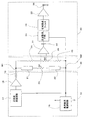
図2は、本実施形態の荷重検出装置における主要部の回路構成を示している。この荷重検出装置は、交流電圧生成回路部10と、ブリッジ回路部20と、検出回路部30とを有している。
FIG. 2 shows a circuit configuration of a main part in the load detection device of the present embodiment. The load detection device includes an AC voltage
交流電圧生成回路部10は、基準直流電源回路16と、基準電圧を中心に正弦波を発生させる正弦波発振回路17と、入力インピーダンスの高いバッファアンプ18と、ブリッジ回路部20に流す電流の大きさを調節する電流制限固定抵抗器19とを有している。
The AC voltage
ブリッジ回路部20は、平衡調整用可変抵抗器23を間に挟んで直列に接続された磁歪センサ素子21、22と、平衡調整用可変抵抗器26を間に挟んで直列に接続されたブリッジ固定抵抗器24、25を有している。このブリッジ回路部20は、図1(c)に示すブリッジ回路と基本的に同一の構成を有している。
The
検出回路部30は、ブリッジ回路部20の差動電圧を増幅する交流差動増幅回路31と、この出力信号中の直流成分をカットする直流阻止コンデンサ32と、このコンデンサ32を通過してきた交流信号を整流する全波整流回路33と、全波整流回路33からの出力電圧を平滑化する低域通過フィルタ34と、ゲイン調整用可変抵抗器を備えた直流増幅回路35と、信号電圧出力端子36とを備えている。
The
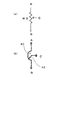
次に、図3を参照して、ブリッジ回路部20の構成を詳しく説明する。
Next, the configuration of the
本実施形態におけるブリッジ回路部20では、図3に示すように、第1ブリッジアームBA1が磁歪センサ素子21を含み、第2ブリッジアームBA2が磁歪センサ素子22を含んでいる。
In the
磁歪センサ素子21、22は、いずれも、磁歪材料から形成された磁歪部材と、この磁歪部材を取り囲むコイルを有している。磁歪センサ素子21のコイルは、第1の入力点N1と第1の出力点S1とを電気的に接続し、磁歪センサ素子22のコイルは、第1の出力点S1と第2の入力点N2とを電気的に接続している。
Each of the
第1ブリッジアームBA1と第2ブリッジアームBA2との接続ノード(第1の出力点S1)は、平衡調整用可変抵抗器23の中に存在している。本実施形態で用いる平衡調整用可変抵抗器23は、図4に示すような構成を有しており、端子Aと端子Bとの間に存在する抵抗体40の抵抗値Rは固定値であるが、端子Cに接続された接触子42と抵抗体40との接続点(接触位置)を移動させることにより、端子Aと端子Cとの間の抵抗値を可変にすることができる。端子Aと端子Cとの間の抵抗値を増加させるとき、端子Bと端子Cとの間の抵抗値は低下することになる。接触子42と抵抗体40との間の接続点の位置により、抵抗体40を直列に接続された2つの抵抗部分に分けて考えることができる。これらの2つの抵抗部分の抵抗値を、それぞれ、R1およびR2とすると、R=R1+R2の関係が成立する。
A connection node (first output point S1) between the first bridge arm BA1 and the second bridge arm BA2 exists in the balance adjusting
再び図3を参照する。 Refer to FIG. 3 again.
第1ブリッジアームBA1のインピーダンスは、磁歪センサ素子21のインピーダンスと、平衡調整用可変抵抗器23における抵抗成分R1との和によって表される(配線抵抗は無視する。以下同様。)。一方、第2ブリッジアームBA2のインピーダンスは、磁歪センサ素子7のインピーダンスと、平衡調整用可変抵抗器23における抵抗成分R2との和によって表される。したがって、第1および第2ブリッジアームBA1、BA2の合計のインピーダンスは、磁歪センサ素子21、22の合計インピーダンスと、平衡調整用可変抵抗器23における抵抗値Rとの和によって表される。抵抗値Rは、磁歪センサ素子21のインピーダンスと磁歪センサ素子22のインピーダンスの差程度の大きさを有していればよく、各磁歪センサ素子21、22のインピーダンスに比べて充分に小さな値に設定することが可能である。本実施形態で使用する各磁歪センサ素子21、22のインピーダンスは、50〜100Ωの範囲にあるが、2つの磁歪センサ素子21、22の間にあるインピーダンスの差異は5〜10Ω程度であるため、抵抗値Rは例えば5〜10Ωの範囲の大きさを有するものが用いられ得る。
The impedance of the first bridge arm BA1 is represented by the sum of the impedance of the
一方、ブリッジ回路部20における第3ブリッジアームBA3は固定抵抗器24を含み、第4ブリッジアームBA4は固定抵抗器25を含んでいる。そして、第3ブリッジアームBA3と第4ブリッジアームBA4との接続ノード(第2の出力点S2)は、平衡調整用可変抵抗器26の中に存在している。平衡調整用可変抵抗器26の構造は、平衡調整用可変抵抗器23の構造と同様である。
On the other hand, the third bridge arm BA3 in the
本実施形態では、上述のように、平衡調節可変抵抗器23、26における端子C(図4参照)を図2に示す検出回路部30に接続している。このため、交流差動増幅回路31の入力インピーダンスを高く設定すると、ブリッジ回路部20の出力点と検出回路部30の信号入力部との間に電流を流さない構成を実現できる。このことによる効果は、後に説明する。
In the present embodiment, as described above, the terminal C (see FIG. 4) in the balance adjustment
(磁歪センサ素子)
次に、図5および図6を参照しながら、本実施形態の荷重検出装置で用いる磁歪センサ素子21、22の配置例を説明する。本実施形態の荷重検出装置は、荷重測定が必要となる種々の機器に用いられ得るが、ここでは、乗り物の操舵軸に取り付けられ、トルクを検出するために用いられる例について説明する。
(Magnetostrictive sensor element)
Next, an arrangement example of the
図5は、操舵軸に取り付けられた荷重センサユニット5を示す斜視図であり、図6は、荷重センサユニット5における操舵軸を横切る断面を示す図である。図5に示す荷重センサユニット5は、上操舵軸3aと下操舵軸3bとを連結する部分に設けられている。下操舵軸3bは、その上端部に位置する上操舵軸3aとの連結部にセンサ収容部51を有し、このセンサ収容部51内には、上操舵軸3aの下端部の外周部の一部から突出している押圧部3cが突入している。
FIG. 5 is a perspective view showing the
押圧部3cは、上操舵軸3aの外周部からセンサ収容部51内に突出している。センサ収容部51は、押圧部3cを境にして左右の2つの部分に分割され、右側の部分には磁歪センサ素子21が収容され、また左側の部分には磁歪センサ素子22が収容されている。
The
磁歪センサ素子21は、その底部とセンサ収容部51の一方の側壁との間に設けられたばね53Aによって磁歪センサ素子21の底部が押圧部3cに向かう方向に押圧され、これにより磁歪センサ素子21の底部と反対側に突出して設けられた被押圧部55Aが押圧部3cに当接して押圧するようになっている。
The
磁歪センサ素子22も同様に、この磁歪センサ素子22の底部とセンサ収容部51の他方の壁との間に設けられたばね53Bによって磁歪センサ素子22の底部が押圧部3cに向かう方向に押圧され、これにより、磁歪センサ素子22の底部と反対側に突出して設けられた被押圧部55Bが押圧部3cに当接して押圧するようになっている。
Similarly, the
磁歪センサ素子21、21は、磁気変化を検知する磁気コイルを有し、各磁歪センサに対応する被押圧部55A、55Bとともに逆磁歪効果を利用した磁歪センサを構成している。被押圧部55A、55Bが押圧部3cによって押圧されて歪むことにより、この歪みに応じて生じる被押圧部55A、55Bの磁気変化、具体的には透磁率または磁化特性の変化を磁歪センサ素子21、22の磁気コイルのインピーダンスの変化として検知することができる。
The
荷重センサユニット5を用いて操舵軸のトルクを検出する場合、ハンドルを例えば左方向に操作すると、ハンドルに連結されている上操舵軸3aは、矢印301で示すように回転する。このように上操舵軸3aが回転すると、その押圧部3cは上操舵軸3aとともに矢印302に示すように回動し、この上操舵軸3aの回転力に応じて被押圧部55Aおよび磁歪センサ素子21を矢印303で示すようにばね53Aに抗して押圧する。
When detecting the torque of the steering shaft using the
このように上操舵軸3aの回転力により押圧部3cを介して被押圧部55Aが押圧されると、被押圧部55Aは上操舵軸3aの回転力に応じて歪むことになり、この歪みに応じて被押圧部55Aに磁気変化が生じる。この磁気変化は磁歪センサ素子21を構成する磁気コイルで上操舵軸3aの回転トルクとして検知されることになる。
As described above, when the pressed
ハンドルを反対の右方向に操作した場合には、磁歪センサ素子21、被押圧部55A、ばね53Aの代わりに磁歪センサ素子22、被押圧部55B、ばね53Bがそれぞれ同様の作用を行うものであり、単に回転方向や押圧方向が異なるのみであるので、その説明は省略する。
When the handle is operated in the opposite right direction, the
ばね53Aに対して組立時に一定の荷重、例えばFニュートン(N)を予め印加しておくと、押圧部3cにより被押圧部55Aと磁歪センサ素子21が押圧される場合に、この押圧荷重がFニュートンを超えない限りにおいては、被押圧部55Aと磁歪センサ素子21は動かないが、Fニュートンを超えると、被押圧部55Aと磁歪センサ素子21は右方向に移動するため、被押圧部55Aと磁歪センサ素子21にはFニュートン以上の押圧荷重がかからないという過荷重防止機能を実現するようになっている。
If a constant load, for example, F Newton (N) is applied to the
荷重検出装置における磁歪センサ素子に対する荷重印加方法は、上述した例に限定されず、種々の印加方法に適用可能である。ただし、本発明の好ましい実施形態においては、一対の磁歪センサ素子のいずれか一方のみに荷重を印加し、そのとき荷重が印加されていない他方の磁歪センサ素子を測定のレファランスとして利用している。このため、本実施形態の荷重検出装置による場合、磁歪センサ素子のいずれか一方に測定対象の荷重を印加する必要がある。このことは、本発明の物理量測定装置で所定の物理量を測定する場合のすべてに成立することである。 The load application method for the magnetostrictive sensor element in the load detection device is not limited to the above-described example, and can be applied to various application methods. However, in a preferred embodiment of the present invention, a load is applied to only one of the pair of magnetostrictive sensor elements, and the other magnetostrictive sensor element to which no load is applied is used as a measurement reference. For this reason, in the case of the load detection device of the present embodiment, it is necessary to apply the load to be measured to one of the magnetostrictive sensor elements. This is true for all cases where a predetermined physical quantity is measured by the physical quantity measuring device of the present invention.
なお、図5および図6では、アンプや抵抗器などの回路要素を集積した電子回路基板は図示していないが、これの電子回路基板は、磁歪センサ素子の近傍に配置されていても良いし、磁歪センサ素子から離れた位置において他の制御回路部と一体化されていても良い。 5 and 6, an electronic circuit board on which circuit elements such as an amplifier and a resistor are integrated is not shown, but the electronic circuit board may be arranged in the vicinity of the magnetostrictive sensor element. Further, it may be integrated with another control circuit unit at a position away from the magnetostrictive sensor element.
(荷重検出動作)
以下、図2を参照しながら、本実施形態の荷重検出装における測定動作の詳細を説明する。
(Load detection operation)
Hereinafter, the details of the measurement operation in the load detection device of the present embodiment will be described with reference to FIG.
まず、基準直流電源回路16は、5V(ボルト)の電源電圧(不図示)に基づいて2.5Vの基準直流電圧を出力する。この基準直流電圧は正弦波発振回路17に入力される。正弦波発振回路17は、この基準直流電圧を中心に振動する正弦波の発振信号を出力する。正弦波発振信号の周波数は例えば1kHzに設定され、振幅Vpp(ピークtoピーク)は例えば2Vに調節される。
First, the reference DC
この発振信号は、ハイインピーダンスのバッファアンプ18および電流制限固定抵抗器19を介してブリッジ回路部20に供給される。
This oscillation signal is supplied to the
磁歪センサ素子21、22の一方に荷重が加えられると、磁歪効果により、荷重の加えられた磁歪センサ素子21または磁歪センサ素子22における磁歪材料の初透磁率が変化する。その結果、その磁歪センサ素子21または磁歪センサ素子22のインピーダンスが初期値から変化するため、第1ブリッジアームと第2ブリッジアームとの間でインピーダンスのバランスが崩れる。
When a load is applied to one of the
上記のようにしてインピーダンスのバランスが崩れると、ブリッジ回路部20の第1の出力点S1と第2の出力点S2との間で差動電圧が発生する。この差動電圧は、検出回路部30における交流差動増幅回路31で増幅される。交流差動増幅回路31から出力される信号の交流成分は、直流阻止コンデンサ32を通過して全波整流回路33に入力される。
When the impedance balance is lost as described above, a differential voltage is generated between the first output point S1 and the second output point S2 of the
全波整流回路33は、整流用ダイオードなどから構成されており、順方向電圧以下では整流動作が行えず、不感帯となる。このような事態を避け、全波整流回路33で適切な整流動作を行なわせるためには、交流差動増幅回路31のゲインを可能な限り高い値に設定しておくことが好ましい。本実施形態では、磁歪センサ素子21、22の一方に絶対最大定格の荷重が印加された場合においても交流差動増幅回路31の出力が飽和しない最大レベルに交流差動増幅回路31のゲインを調節している。
The full-
本実施形態では、全波整流回路33における検出感度を向上させるため、全波整流を行なった後、信号振幅を2倍に増幅している。増幅された信号は、低域通過フィルタ34に入力される、励磁電流の周波数(発振周波数)に等しい周波数を有する交流成分を十分に除去するため、低域通過フィルタ34のカットオフ周波数を発振周波数の1/10以下に設定している。
In the present embodiment, in order to improve the detection sensitivity in the full-
低域通過フィルタ34の出力は、直流増幅回路35で増幅された後、信号電圧出力端子36から出力される。信号電圧出力端子36上の信号電圧は、磁歪センサ素子21または磁歪センサ素子22の一方に印加された荷重に対応した大きさを有している。
The output of the low-
(初期調整)
荷重を高い精度を測定するためには、初期調整を行なう必要がある。本実施形態では、2種類の初期調整を行なっている。第1の初期調整は、磁歪センサ素子21、22に荷重を印加しない状態で信号電圧出力端子36から出力される信号電圧をゼロに設定する「ゼロ点調整」である。第2の初期調整は、磁歪センサ素子21、22の一方に最大荷重を印加した状態で信号電圧出力端子36から出力される信号電圧を所定の要求値に設定する「感度調整」である。
(Initial adjustment)
In order to measure the load with high accuracy, it is necessary to perform initial adjustment. In this embodiment, two types of initial adjustments are performed. The first initial adjustment is “zero point adjustment” in which the signal voltage output from the signal
本実施形態では、交流差動増幅回路31から出力される交流出力を測定しながら、この交流出力の振幅値が最小となるように平衡調整用可変抵抗器23および26を調節する(ゼロ点調整)。次に、直流増幅回路35の直流出力を測定しながら、磁歪センサ素子21または磁歪センサ素子22に400ニュートンの荷重を印加する。この荷重が印加された状態で直流増幅回路35から出力される直流電圧が例えば3.5Vに等しくなるように、直流増幅回路35のゲインを調整する(感度調整)。
In the present embodiment, while measuring the AC output output from the AC
なお、バッファアンプとして機能するオペアンプ13の出力電流は10mA程度である。本実施形態では、並列型のブリッジ回路を用いる代わりに、直列型のブリッジ回路を採用しているため、磁歪センサ素子21、22が設けられている第1および第2ブリッジアームに流れる電流を、第3および第4ブリッジアームに流れる電流よりも大きくすることができる。このため、2つの磁歪センサ素子21、22の間に初透磁率の差異などに起因する初期特性のばらつきが存在していたとしても、充分に大きな電流を磁歪センサ素子21、22に流すことができ、磁歪センサ素子21、22の出力特性の差異が検出精度を低下させないようにすることが可能である。
Note that the output current of the operational amplifier 13 functioning as a buffer amplifier is about 10 mA. In the present embodiment, instead of using a parallel bridge circuit, a series bridge circuit is employed, so that the current flowing through the first and second bridge arms provided with the
なお、交流差動増幅回路31の検出感度を向上させるためには、交流差動増幅回路31に入力される信号の差動振幅レンジを広げることが重要である。最大荷重時に差動出力電圧の振幅が最大となるためには、ブリッジ回路における第1ブリッジアームのインピーダンスを第2ブリッジアームのインピーダンスと略等しく設定する必要がある。第1ブリッジアームと第2ブリッジアームとの間でインピーダンスと略等しく設定すると、差動振幅レンジの中央付近を基準電圧付近に設定することができるため、交流差動増幅回路31のゲインを向上させることができる。
In order to improve the detection sensitivity of the AC
本実施形態で用いる磁歪センサ素子21、22のインピーダンスは相互に略等しいため、並列型のブリッジ回路を採用した従来例に比べ、第1ブリッジアームのインピーダンスを第2ブリッジアームのインピーダンスと略等しく設定することが容易である。これは、磁歪センサ素子21、22を直列に接続することによる利点の1つである。
Since the impedances of the
また、磁歪センサ素子21のインピーダンスと磁歪センサ素子22のインピーダンスが略等しいと、平衡調整用可変抵抗器23に要求される抵抗変化の範囲を、各磁歪センサ素子21、22のインピーダンスに比べて格段に小さくすることができる。このことは、第1および第2ブリッジアームの全体のインピーダンスを低減することに寄与するとともに、平衡調整用可変抵抗器23が有する温度特性の影響を低減することにも役立つ。通常、平衡調整用可変抵抗器23の抵抗は比較的大きな温度依存性を有しているため、ゼロ点調整を行なった後、平衡調整用可変抵抗器23の温度が変動すると、それに応じてインピーダンスバランスが崩れやすくなる。しかし、本実施形態によれば、平衡調整用可変抵抗器23の抵抗値をセンサインピーダンスに比べて充分小さい値に設定できるため、抵抗の温度特性に起因する影響が及びにくい。
Further, when the impedance of the
(平衡調整)
以下、本実施形態における平衡調整の方法を説明する。なお、「平衡調整」とは、磁歪センサ素子21、22のいずれにも荷重を印加していない状態(無荷重状態)において、ブリッジ回路部20から出力される差動電圧(出力点S1、S2の間の電圧)をゼロにすることである。
(Balance adjustment)
Hereinafter, the balance adjustment method in the present embodiment will be described. The “balance adjustment” means a differential voltage (output points S1, S2) output from the
まず、無荷重状態で平衡調整用可変抵抗器23、26のいずれか一方を調節し、交流差動増幅回路31の出力振幅を最小にする。次に、無荷重状態で平衡調整用可変抵抗器23、26の他方を調節して、交流差動増幅回路31の出力振幅を最小にする。このような調節作業を、2つの平衡調整用可変抵抗器23、26について交互に実行することにより、出力振幅を極小化すると、原理的には残差電圧を完全にゼロに低減すること(完全平衡)が可能である。
First, one of the balance adjusting
ゼロ点調整が不完全なために残差電圧がゼロに調節されていないと、磁歪センサ素子21、22の一方に荷重が印加されたとき、その出力信号が一時的に低下する。その結果、2つ磁歪センサ素子間に出力特性差が生じることになる。しかし、本実施形態では、このような現象を防止することができる。
If the residual voltage is not adjusted to zero because the zero point adjustment is incomplete, when a load is applied to one of the
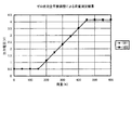
図7は、従来の並列型ブリッジ回路を用いて平衡調節を行なった場合における2つの磁歪センサ素子の出力特性を示すグラフであり、図8は、完全平衡調整を行なった本実施形態におけるブリッジ回路から得られる2つの磁歪センサ素子の出力特性を示すグラフである。図7からわかるように、平衡調節が不完全であると、2つの磁歪センサ素子の出力差が大きい。これに対し、完全平衡調整が行われた本実施形態では、図8からわかるように、2つの磁歪センサ素子間で出力差が殆ど無くなっている。 FIG. 7 is a graph showing output characteristics of two magnetostrictive sensor elements when balance adjustment is performed using a conventional parallel bridge circuit, and FIG. 8 is a bridge circuit according to the present embodiment in which complete balance adjustment is performed. 6 is a graph showing output characteristics of two magnetostrictive sensor elements obtained from As can be seen from FIG. 7, if the balance adjustment is incomplete, the output difference between the two magnetostrictive sensor elements is large. On the other hand, in this embodiment in which perfect balance adjustment is performed, as can be seen from FIG. 8, there is almost no output difference between the two magnetostrictive sensor elements.
図2に示す回路構成によれば、完全平衡調整が実現し、残差電圧をゼロにすることが可能になる。残差電圧がゼロになるということは、無荷重時の出力電圧レベルがゼロになることを意味している。 According to the circuit configuration shown in FIG. 2, perfect balance adjustment is realized, and the residual voltage can be made zero. When the residual voltage becomes zero, it means that the output voltage level under no load becomes zero.
なお、図7および図8においては、微小荷重領域の出力が0(ゼロ)ではなく、約0.5Vの値を示している。これは「断線検出」のためである。以下、この「断線検出」について説明する。 7 and 8, the output of the minute load region is not 0 (zero) but shows a value of about 0.5V. This is for “disconnection detection”. Hereinafter, this “disconnection detection” will be described.
本実施形態の荷重検出装置において、完全平衡調節によって残差電圧をゼロにすると、磁歪センサ素子に印加される荷重がゼロのとき、直流増幅回路35の入力部における信号電圧はゼロボルト(0V)になる。
In the load detection device of the present embodiment, when the residual voltage is made zero by complete balance adjustment, when the load applied to the magnetostrictive sensor element is zero, the signal voltage at the input portion of the
荷重検出装置を乗り物などのシステムに用いる場合、信号電圧出力端子36の出力信号は、ハーネスを介してエンジンコントロールユニットなどに供給される。このハーネスなどの配線の一部に断線が生じた場合、荷重検出装置に荷重が印加されているか否かによらず、0Vの電圧がエンジンコントロールユニットなどに供給されることになる。このため、荷重が印加されていない状態か、断線した状態かを識別することが困難になる。
When the load detection device is used in a system such as a vehicle, the output signal of the signal
そこで、本実施形態では、直流増幅回路35の入力電圧が0Vであっても、直流増幅回路35の出力電圧が0Vからシフトした値(約0.5V)となるように直流増幅回路35を設計している。すなわち、本実施形態の荷重検出装置からは、磁歪センサ素子に荷重が印加されているときでも、荷重が印加されていないときでも、動作時は常に、「ゼロではない値(段線時と区別できる値)」を示す信号が出力される。このため、例えばエンジンコントロールユニットが荷重検出装置から基準値(例えば0.5V)を下回る出力電圧を受け取った場合は、断線が生じていることを判断することができるため、断線検知が実現する。
Therefore, in this embodiment, even if the input voltage of the
なお、平衡調整回路の違いが残差電圧にどの程度影響を与えるかを調べた。不完全平衡調整回路の場合、その残差電圧レベルとばらつきが大きいのに対して、完全平衡調整回路によるデータから、測定ダイナミックレンジの拡大に効果があることが分かった。 It was examined how much the difference in the balance adjustment circuit affects the residual voltage. In the case of the imperfect balance adjustment circuit, the residual voltage level and the variation are large, but from the data of the complete balance adjustment circuit, it has been found that the measurement dynamic range is effective.
前述のようにゼロ点の安定度は、センサの左右ばらつきや微小荷重の検出精度への影響が大きい。そのためこのゼロ点は極力安定化させる必要がある。 As described above, the stability of the zero point has a great influence on the left-right variation of the sensor and the detection accuracy of a minute load. Therefore, it is necessary to stabilize this zero point as much as possible.
図2に示す回路を構成する配線、抵抗器、アンプ、コンデンサなどの回路構成要素は、1つの電子回路基板上に搭載されることが好ましい。電子回路基板は、調整後に樹脂注型によって封止されることが好ましい。このようにして電子回路基板の表面を樹脂で覆うことにより、平衡調整用可変抵抗器23、26の可動部が動くことは無い。ただし、この平衡調整用可変抵抗器23、26の接触子42(図4)は完全に固定されるわけではないため、図4に示す抵抗体40と接触子42との接触部の抵抗値(接触抵抗値)は不安定であり、経時変化を起こしやすい。
Circuit components such as wiring, resistors, amplifiers, and capacitors constituting the circuit shown in FIG. 2 are preferably mounted on one electronic circuit board. The electronic circuit board is preferably sealed by resin casting after adjustment. By thus covering the surface of the electronic circuit board with the resin, the movable parts of the balance adjusting
従来の並列型のブリッジ回路において可変抵抗器を用いる例では、接触子に電流が流れるような構成が採用されている。そのような回路では、接触抵抗値の変化が図4(b)に示す端子A−B間の抵抗値を変化させるため、ブリッジ回路の平衡点を変化させる原因となる。 In an example in which a variable resistor is used in a conventional parallel bridge circuit, a configuration is adopted in which a current flows through a contact. In such a circuit, the change in the contact resistance value changes the resistance value between the terminals A and B shown in FIG. 4B, which causes a change in the equilibrium point of the bridge circuit.
しかしながら、本実施形態のブリッジ回路部20では、交流差動増幅回路31の入力インピーダンスが高く設定されているため、平衡調整用可変抵抗器23、26の接触子には電流がほとんど流れない。したがって、平衡調整用可変抵抗器23、26の接触子に存在する接触抵抗値が経年的に変化するなどに理由によって変動したとしても、検出電圧に影響を与えることはなく、測定の信頼性が向上する。
However, in the
なお、本発明で用いる直列型ブリッジ回路においても、可変抵抗器をブリッジアームの少なくとも一方(好ましくは両方)に挿入しても、平衡調整は可能である。しかし、この場合は、各可変抵抗器における接触子に電流が流れるため、接触抵抗の変動による安定性の低下が生じえる。ただし、このような場合でも、接触抵抗の安定性を充分に向上させた可変抵抗器を用いれば、ゼロ点安定性の低下を避けることは可能である。 In the series bridge circuit used in the present invention, balance adjustment is possible even if a variable resistor is inserted into at least one (preferably both) of the bridge arms. However, in this case, since a current flows through the contacts in each variable resistor, stability can be degraded due to fluctuations in contact resistance. However, even in such a case, if a variable resistor having sufficiently improved contact resistance stability is used, it is possible to avoid a decrease in zero point stability.
[実施形態2]
以下、実施形態1の荷重検出装置を備えた水上乗り物の実施形態を説明する。ここでは、水上乗り物の本実施形態として、水ジェット推進艇を説明する。水ジェット推進艇は、エンジンで駆動されるジェット推進機で加圧された水をノズルから噴射することにより、その反動で推進することができる。このような乗り物に荷重検出装置などの物理量検出装置を用いる場合、海上という厳しい環境で使用されるため、耐久性や長期信頼性が必要となるため、本発明の物理量検出装置が用いられて有利な効果を発揮することができる。
[Embodiment 2]
Hereinafter, an embodiment of a water vehicle including the load detection device of the first embodiment will be described. Here, a water jet propulsion boat will be described as this embodiment of a water vehicle. The water jet propulsion watercraft can be propelled by its reaction by jetting water pressurized by a jet propulsion device driven by an engine from a nozzle. When a physical quantity detection device such as a load detection device is used for such a vehicle, since it is used in a harsh environment such as the sea, durability and long-term reliability are required. Therefore, the physical quantity detection device of the present invention is advantageous. Can be effective.
図9は、本実施形態の水ジェット推進艇100の概略構成を示している。水ジェット推進艇の艇体100は、下部のハル部材101と上部のデッキ部材102とから構成され、デッキ部材102上に跨座式シート103が設けられている。このシート103の前方に設けられているのが操舵用のハンドル104である。
FIG. 9 shows a schematic configuration of the water
艇体内には、駆動源であるエンジン1が配設され、エンジン1の出力軸105にはジェット推進機106のインペラが107接続されている。従って、エンジン1でジェット推進機106のインペラ107が回転駆動されると、艇底の水吸引口108から水が吸引され、ジェット推進機106内で加圧・加速された水はノズル109から後方に噴射され、その反動で自艇が前進する。また、ハンドル104を操舵すると、ノズル109の後方のディフレクタと呼ばれる舵取り装置が揺動して、自艇を左右に旋回することができる。つまり、ハンドル104を操舵すると噴射される水の向きが変わり、これにより自艇を旋回させることができるようになっている。なお、自艇を後進させる場合には、リバースレバー120を操作して、ノズル109後方のリバースゲート121を昇降し、ノズル109から噴射される水の向きを自艇前方に変換することにより可能となる。なお、図中の符号112は、リバースレバー120操作により自艇が後進していることを検出するリバーススイッチである。
An
図10は、ハンドル104の構成を示している。ハンドル104は、操舵軸113の回りに回転可能であり、ハンドル104を左右に操舵することができる。ハンドル104の右グリップの近傍には、操艇者の加減速意思に合わせて操作されるスロットルレバー110が設けられている。このスロットルレバー110は、解放時、グリップから離れており、加速する場合には、操艇者がグリップ側に近づけるようにしてスロットルレバー110を握り込む。スロットルレバー110を戻すということは、スロットルレバー110を解放することである。
FIG. 10 shows the configuration of the
操舵軸113には、ハンドル104への操舵力、具体的には操舵トルクを検出するための操舵トルクセンサ111が設けられている。この操舵トルクセンサ111は、実施形態1の磁歪式荷重検出装置と同様の構成を有している。ハンドル104は所定角度まできると、ハンドル軸が規制されて動かなくなる。操舵トルクセンサ111は、更にハンドル104に操舵力を与えた状態で、ハンドル104に係る操舵トルクを検出するロードセルとして機能する。なお、操舵トルクセンサ111の構成は、図5および図6に示す荷重センサユニットの具体的構成に限定されず、磁歪センサ素子の配置や機械的な接続関係は、多様な態様で実現することができる。スロットルレバー110には、操艇者によるスロットルレバー110の操作量、即ちスロットル開度を検出するスロットル開度センサ114が設けられている。
The steering
図11は、水ジェット推進艇100のエンジン及びその制御装置の概略を示している。本実施形態のエンジン201は、比較的小排気量のストロークエンジン201であり、シリンダボディ202、クランクシャフト203、ピストン204、燃焼室205、吸気管206、吸気バルブ207、排気管208、排気バルブ209、点火プラグ210、点火コイル211を備えている。また、吸気管206内には、スロットルレバー110の開度に応じて開閉されるスロットルバルブ212が設けられ、このスロットルバルブ212の下流側の吸気管206に、燃料噴射装置としてのインジェクタ213が設けられている。このインジェクタ213は、燃料タンク219内に配設されているフィルタ218、燃料ポンプ217、圧力制御バルブ216に接続されている。
FIG. 11 schematically shows the engine of the water
吸気管206のスロットルバルブ212の近傍には、スロットルバルブ212をバイパスするバイパス路206aが設けられ、このバイパス路206aにバイパス路の開度を調整するバイパスバルブ214(減速時エンジン出力制御手段)が設けられている。バイパスバルブ214は、アイドルバルブのように、スロットルバルブ212の開度とは個別にエンジン201側への吸気流量を調整してエンジンの出力、この場合はエンジントルクを制御する。なお、バイパス路206aの開度、つまりエンジントルクは、例えば電磁デューティバルブのように、バイパスバルブ214を駆動するためのアクチュエータ223への電流値、またはデューティ比を制御することにより制御可能である。
A
エンジン201の運転状態並びにバイパスバルブ214のアクチュエータ223の駆動状態は、エンジンコントロールユニット215によって制御され、エンジンコントロールユニット215は、マイクロコンピュータ等の演算処理装置を備えている。エンジンコントロールユニット215の制御入力、つまりエンジン201の運転状態を検出する手段として、クランクシャフト203の回転角度、つまり位相を検出したり、クランクシャフト203自身の回転速度を検出したりするためのクランク角度センサ220、シリンダボディ202の温度又は冷却水温度、即ちエンジン本体の温度を検出する冷却水温度センサ221、排気管208内の空燃比を検出する排気空燃比センサ222、吸気管206内の吸気圧力を検出するための吸気圧力センサ224、吸気管206内の温度、即ち吸気温度を検出する吸気温度センサ225が設けられている。
The operating state of the
通常は、スロットルレバー110に設けられたスロットル開度センサ114(スロットル開度センサ)の出力信号がエンジントルクの制御に用いられるが、オフスロットル時には、操舵用ハンドル104に設けられた操舵トルクセンサ(磁歪式荷重センサ)111の出力信号もエンジントルクの制御に用いることができる。エンジンコントロールユニット215は、これらのセンサの検出信号を入力し、燃料ポンプ217、圧力制御バルブ216、インジェクタ213、点火コイル211、およびアクチュエータ223に制御信号を出力する。
Normally, the output signal of the throttle opening sensor 114 (throttle opening sensor) provided on the
本実施形態によれば、完全平衡調整がなされた荷重検出装置を用いて操舵トルクを検出するため、荷重の小さな領域でも測定精度が高く、また信頼性も向上している。本実施形態では、乗り物として水ジェット推進艇の実施形態を説明したが、本発明の適用範囲は、このような場合に限定されない。 According to the present embodiment, since the steering torque is detected using the load detection device that has been completely balanced, the measurement accuracy is high and the reliability is improved even in a small load region. In the present embodiment, the embodiment of the water jet propulsion boat is described as a vehicle, but the scope of application of the present invention is not limited to such a case.
なお、上記の実施形態で使用しているセンサ素子は、磁歪センサ素子であったが、本発明におけるセンサ素子は、これに限定されるものではなく、例えば磁気変化の変わりに静電容量の変化、圧電効果、電気抵抗の変化を利用するセンサ素子であってもよい。静電容量の変化を利用するセンサの場合には、被押圧部が静電容量の電極で構成され、所定の静電容量変化検出手段が、操舵軸の回転力によって電極が押圧されたことによる静電容量の変化を、被押圧部の変化として検出することになる。また、圧電効果を利用するセンサの場合には、被押圧部が圧電素子で構成され、所定の圧電変化検出手段が、操舵軸の回転力によって圧電素子が押圧されたことによる圧電素子の電気的変化を、被押圧部の変化として検出することになる。更に、電気抵抗の変化を利用するセンサの場合には、被押圧部が抵抗手段で構成され、所定の抵抗変化検出手段が、操舵軸の回転力によって抵抗手段が押圧されたことによる抵抗手段の電気抵抗の変化を、被押圧部の変化として検出することになる。 The sensor element used in the above embodiment is a magnetostrictive sensor element. However, the sensor element in the present invention is not limited to this, for example, a change in capacitance instead of a magnetic change. In addition, a sensor element using a change in piezoelectric effect or electrical resistance may be used. In the case of a sensor that uses a change in capacitance, the pressed portion is constituted by a capacitance electrode, and the predetermined capacitance change detection means is caused by the electrode being pressed by the rotational force of the steering shaft. A change in capacitance is detected as a change in the pressed portion. Further, in the case of a sensor using the piezoelectric effect, the pressed portion is composed of a piezoelectric element, and the predetermined piezoelectric change detecting means is electrically connected to the piezoelectric element due to the pressing of the piezoelectric element by the rotational force of the steering shaft. The change is detected as a change of the pressed part. Further, in the case of a sensor that uses a change in electrical resistance, the pressed portion is configured by a resistance means, and the predetermined resistance change detection means is a resistance means that is caused by the resistance means being pressed by the rotational force of the steering shaft. A change in electrical resistance is detected as a change in the pressed portion.
なお、各種のセンサ素子の中でも、本発明は、磁歪式センサ素子を使用する場合に特に顕著な効果を発揮することができる。これは、磁歪センサ素子を使用する場合において、前述した理由から、センサ素子に大きな電流を流すことが特性ばらつきの影響解消に役立つのに対して実際には大きな電流を流すことができないという問題があるからである。したがって、このような問題を有する磁歪センサ素子を用いて正確な荷重測定を行う上で、本発明は顕著な効果を発揮することができる。 Of the various sensor elements, the present invention can exert a particularly remarkable effect when the magnetostrictive sensor element is used. This is because when a magnetostrictive sensor element is used, for the reason described above, flowing a large current to the sensor element helps to eliminate the influence of characteristic variation, but in reality, a large current cannot flow. Because there is. Therefore, the present invention can exert a remarkable effect in performing accurate load measurement using the magnetostrictive sensor element having such a problem.
本発明の物理量検出装置は、陸上または海上で使用される各種の乗り物における荷重検出などに好適に用いられるため、産業上の利用可能性が高い。 Since the physical quantity detection device of the present invention is suitably used for load detection in various vehicles used on land or at sea, the industrial applicability is high.
10 交流電圧生成回路部
20 ブリッジ回路部
30 検出回路部
16 基準直流電源回路
17 正弦波発振回路
18 バッファアンプ
19 電流制限固定抵抗器
21、22 磁歪センサ素子
23 平衡調整用可変抵抗器
24、25 ブリッジ固定抵抗器
26 平衡調整用可変抵抗器
31 交流差動増幅回路
32 直流阻止コンデンサ
33 全波整流回路
34 低域通過フィルタ
35 直流増幅回路
36 信号電圧出力端子
BA1 第1ブリッジアーム
BA2 第2ブリッジアーム
BA3 第3ブリッジアーム
BA4 第4ブリッジアーム
N1 第1の入力点
N2 第2の入力点
S1 第1の出力点
S2 第2の出力点
100 水ジェット推進艇
101 ハル部材
102 デッキ部材
103 跨座式シート
104 操舵用のハンドル
105 エンジン1の出力軸
106 ジェット推進機
107 インペラ
108 水吸引口
109 ノズル
110 スロットルレバー
111 操舵トルクセンサ
112 リバーススイッチ
113 操舵軸
114 スロットル開度センサ
120 リバースレバー
121 リバースゲート
201 エンジン
202 シリンダボディ
203 クランクシャフト
204 ピストン
205 燃焼室
206 吸気管
206a バイパス路
207 吸気バルブ
208 排気管
209 排気バルブ
210 点火プラグ
211 点火コイル
212 スロットルバルブ
213 インジェクタ
214 バイパスバルブ
215 エンジンコントロールユニット
216 圧力制御バルブ
217 燃料ポンプ
218 フィルタ
219 燃料タンク
220 クランク角度センサ
221 冷却水温度センサ
222 排気空燃比センサ
223 アクチュエータ
224 吸気圧力センサ
225 吸気温度センサ
DESCRIPTION OF SYMBOLS 10 AC voltage generation circuit part 20 Bridge circuit part 30 Detection circuit part 16 Reference | standard DC power supply circuit 17 Sinusoidal oscillation circuit 18 Buffer amplifier 19 Current limiting fixed resistors 21 and 22 Magnetostrictive sensor element 23 Balance adjustment variable resistors 24 and 25 Bridge Fixed resistor 26 Variable resistor 31 for balance adjustment AC differential amplifier circuit 32 DC blocking capacitor 33 Full wave rectifier circuit 34 Low pass filter 35 DC amplifier circuit 36 Signal voltage output terminal BA1 First bridge arm BA2 Second bridge arm BA3 3rd bridge arm BA4 4th bridge arm N1 1st input point N2 2nd input point S1 1st output point S2 2nd output point 100 water jet propulsion boat 101 hull member 102 deck member 103 straddle-type seat 104 Steering handle 105 Output shaft 106 of engine 1 Jet propulsion unit 1 7 Impeller 108 Water suction port 109 Nozzle 110 Throttle lever 111 Steering torque sensor 112 Reverse switch 113 Steering shaft 114 Throttle opening sensor 120 Reverse lever 121 Reverse gate 201 Engine 202 Cylinder body 203 Crankshaft 204 Piston 205 Combustion chamber 206 Intake pipe 206a Bypass Passage 207 intake valve 208 exhaust pipe 209 exhaust valve 210 ignition plug 211 ignition coil 212 throttle valve 213 injector 214 bypass valve 215 engine control unit 216 pressure control valve 217 fuel pump 218 filter 219 fuel tank 220 crank angle sensor 221 cooling water temperature sensor 222 Exhaust air / fuel ratio sensor 223 Actuator 224 Intake pressure sensor 225 Intake air temperature sensor
Claims (14)
前記ブリッジ回路は、
前記第1の入力点と前記第1の出力点とを電気的に接続する第1ブリッジアーム、前記第1の出力点と前記第2の入力点とを電気的に接続する第2ブリッジアーム、前記第1の入力点と前記第2の出力点とを電気的に接続する第3ブリッジアーム、および、前記第2の出力点と前記第2の入力点とを電気的に接続する第4ブリッジアームを有し、
前記第1ブリッジアームは、測定対象となる物理量に応じてインピーダンスが変化する第1のセンサ素子を含み、かつ、前記第2ブリッジアームは、前記物理量に応じてインピーダンスが変化する第2のセンサ素子を含み、
前記第1および第2ブリッジアームが有する合計のインピーダンスは、前記第3および第4のブリッジアームが有する合計のインピーダンスよりも小さく設定されており、
前記第1および第2のセンサ素子は、いずれも、荷重に応じてインピーダンスが変化する磁歪センサ素子であり、
測定対象となる物理量は、前記第1および第2のセンサ素子のいずれか任意の一方に加えられた荷重である、物理量検出装置。 A physical quantity detection device comprising a bridge circuit having first and second input points to which an alternating voltage is supplied and first and second output points connected to a differential amplifier circuit,
The bridge circuit is
A first bridge arm that electrically connects the first input point and the first output point; a second bridge arm that electrically connects the first output point and the second input point; A third bridge arm that electrically connects the first input point and the second output point, and a fourth bridge that electrically connects the second output point and the second input point Has an arm,
The first bridge arm includes a first sensor element whose impedance changes in accordance with a physical quantity to be measured, and the second bridge arm has a second sensor element whose impedance changes in accordance with the physical quantity. Including
The total impedance of the first and second bridge arms is set smaller than the total impedance of the third and fourth bridge arms ,
The first and second sensor elements are both magnetostrictive sensor elements whose impedance changes according to the load,
The physical quantity detection device is a physical quantity to be measured , which is a load applied to any one of the first and second sensor elements .
前記第2のセンサ素子は、磁歪材料から形成された第2磁歪部材と、前記第2磁歪部材を取り囲む第2コイルを有する第2の磁歪センサ素子であり、前記第2コイルは、前記第1の出力点と前記第2の入力点とを電気的に接続している、請求項1に記載の物理量検出装置。 The first sensor element is a first magnetostrictive sensor element having a first magnetostrictive member formed of a magnetostrictive material and a first coil surrounding the first magnetostrictive member, and the first coil is the first magnetostrictive sensor element. Are electrically connected to the first output point,
The second sensor element is a second magnetostrictive sensor element having a second magnetostrictive member formed of a magnetostrictive material and a second coil surrounding the second magnetostrictive member, and the second coil is the first magnetostrictive element. The physical quantity detection device according to claim 1 , wherein the output point and the second input point are electrically connected.
前記第1の出力点は、前記平衡調節用可変抵抗素子に接続されている、請求項1から3のいずれかに記載の物理量検出装置。 The bridge circuit includes a variable resistance element for balance adjustment connected in series between the first sensor element and the second sensor element.
The first output point, the equilibrium adjustment is connected to the variable resistance element, a physical quantity detecting device according to any one of claims 1 to 3.
前記第2の出力点は、前記第2の平衡調節用可変抵抗素子に接続されている、請求項5に記載の物理量検出装置。 The bridge circuit includes a second variable resistance element for balance adjustment connected in series between the third bridge arm and the fourth bridge arm sensor element.
The physical quantity detection device according to claim 5 , wherein the second output point is connected to the second balance adjustment variable resistance element.
前記検出回路部は、前記第1のセンサ素子によって測定される前記物理量の値と、前記第2のセンサ素子によって測定される前記物理量の値とが等しいときであっても、ゼロではない値を示す信号を出力することにより、前記検出回路部の出力信号を伝播する配線が断線しているか否かの判断が可能である、請求項1から9のいずれかに記載の物理量検出装置。 A detection circuit unit including the differential amplifier circuit;
The detection circuit unit has a non-zero value even when the physical quantity value measured by the first sensor element is equal to the physical quantity value measured by the second sensor element. by outputting a signal indicating the wiring for propagating the output signal of the detection circuit section is possible determination of whether or not broken, the physical quantity detecting device according to any one of claims 1 to 9.
前記物理量検出装置によって検出される物理量に応じて動作が制御されるエンジンと、
を備えた乗り物。 The physical quantity detection device according to any one of claims 1 to 10 ,
An engine whose operation is controlled according to a physical quantity detected by the physical quantity detection device;
With a vehicle.
前記第1および第2のセンサ素子によって検知すべき物理量をゼロに設定した状態で前記平衡調整用可変抵抗器のいずれか一方を調節することにより、前記第1および第2の出力点の間における差動電圧の振幅を最小にする第1調整工程と、
前記第1および第2のセンサ素子に与える物理量をゼロにした状態で前記平衡調整用可変抵抗器の他方を調節することにより、前記第1および第2の出力点の間における差動電圧の振幅を最小にする第2調整工程と、
を含むブリッジ回路のゼロ点調整方法。 A zero point adjustment method for a bridge circuit in the physical quantity detection device according to claim 6 ,
By adjusting one of the variable resistors for balance adjustment in a state where the physical quantity to be detected by the first and second sensor elements is set to zero, between the first and second output points A first adjustment step for minimizing the amplitude of the differential voltage;
The amplitude of the differential voltage between the first and second output points is adjusted by adjusting the other of the balance adjusting variable resistors in a state where the physical quantity applied to the first and second sensor elements is zero. A second adjustment step that minimizes
Method for adjusting zero point of bridge circuit including
Priority Applications (1)
| Application Number | Priority Date | Filing Date | Title |
|---|---|---|---|
| JP2005150897A JP4657807B2 (en) | 2004-05-31 | 2005-05-24 | PHYSICAL QUANTITY DETECTION DEVICE HAVING BRIDGE CIRCUIT AND ZERO POINT ADJUSTMENT METHOD |
Applications Claiming Priority (2)
| Application Number | Priority Date | Filing Date | Title |
|---|---|---|---|
| JP2004161672 | 2004-05-31 | ||
| JP2005150897A JP4657807B2 (en) | 2004-05-31 | 2005-05-24 | PHYSICAL QUANTITY DETECTION DEVICE HAVING BRIDGE CIRCUIT AND ZERO POINT ADJUSTMENT METHOD |
Publications (2)
| Publication Number | Publication Date |
|---|---|
| JP2006017701A JP2006017701A (en) | 2006-01-19 |
| JP4657807B2 true JP4657807B2 (en) | 2011-03-23 |
Family
ID=35792111
Family Applications (1)
| Application Number | Title | Priority Date | Filing Date |
|---|---|---|---|
| JP2005150897A Expired - Fee Related JP4657807B2 (en) | 2004-05-31 | 2005-05-24 | PHYSICAL QUANTITY DETECTION DEVICE HAVING BRIDGE CIRCUIT AND ZERO POINT ADJUSTMENT METHOD |
Country Status (1)
| Country | Link |
|---|---|
| JP (1) | JP4657807B2 (en) |
Families Citing this family (5)
| Publication number | Priority date | Publication date | Assignee | Title |
|---|---|---|---|---|
| JP5016446B2 (en) * | 2007-01-29 | 2012-09-05 | 日立マクセル株式会社 | Servo signal recording method, servo signal recording apparatus, and magnetic recording medium |
| JP4865685B2 (en) * | 2007-11-26 | 2012-02-01 | 本田技研工業株式会社 | Magnetostrictive torque sensor and electric steering device |
| JP5967803B2 (en) * | 2012-02-25 | 2016-08-10 | 株式会社共和電業 | Strain gauge transducer |
| EP3343190B1 (en) | 2015-10-01 | 2020-02-19 | Yamaha Hatsudoki Kabushiki Kaisha | Magnetostrictive torque sensor |
| JP6988696B2 (en) | 2018-05-30 | 2022-01-05 | 株式会社島津製作所 | Material tester |
Citations (1)
| Publication number | Priority date | Publication date | Assignee | Title |
|---|---|---|---|---|
| JP2003227765A (en) * | 2002-02-04 | 2003-08-15 | Yamaha Motor Co Ltd | Differential amplifier circuit |
Family Cites Families (3)
| Publication number | Priority date | Publication date | Assignee | Title |
|---|---|---|---|---|
| JPS5563711A (en) * | 1978-11-07 | 1980-05-14 | Toshiba Corp | Pressure transducer |
| JPH0615963B2 (en) * | 1986-03-25 | 1994-03-02 | 株式会社アマダ | Eddy current type distance detector |
| JP2967250B2 (en) * | 1992-12-03 | 1999-10-25 | 光洋精工株式会社 | Torque sensor |
-
2005
- 2005-05-24 JP JP2005150897A patent/JP4657807B2/en not_active Expired - Fee Related
Patent Citations (1)
| Publication number | Priority date | Publication date | Assignee | Title |
|---|---|---|---|---|
| JP2003227765A (en) * | 2002-02-04 | 2003-08-15 | Yamaha Motor Co Ltd | Differential amplifier circuit |
Also Published As
| Publication number | Publication date |
|---|---|
| JP2006017701A (en) | 2006-01-19 |
Similar Documents
| Publication | Publication Date | Title |
|---|---|---|
| US7126355B2 (en) | Physical quantity sensing device with bridge circuit and temperature compensating method | |
| US7180311B2 (en) | Physical quantity sensing device with bridge circuit and zero point adjusting method | |
| JP4657807B2 (en) | PHYSICAL QUANTITY DETECTION DEVICE HAVING BRIDGE CIRCUIT AND ZERO POINT ADJUSTMENT METHOD | |
| US7852070B2 (en) | GMR sensor device having AC power supply | |
| JP5987877B2 (en) | Electronic throttle | |
| JP2001124511A (en) | Rotational angle detector | |
| KR20060115649A (en) | Steering system with leads and pulls compensation | |
| US7913579B2 (en) | Magnetostrictive load sensor and movable unit comprising same | |
| JP4657806B2 (en) | Physical quantity detection device provided with bridge circuit and temperature compensation method | |
| US6704665B2 (en) | Torque sensor abnormality detecting device | |
| JP2006256067A (en) | Method and apparatus for controlling pressure of electric injection molding machine | |
| EP0949744B1 (en) | Electromagnetic actuator with function detecting position of driven member | |
| FR2835053A1 (en) | RACE SENSOR COMPRISING A MAGNETOELECTRIC CONVERTER ELEMENT | |
| JPH04279804A (en) | Sensor for varying amount | |
| US6329897B1 (en) | Rotary position sensor using a strain gage | |
| JP2001153702A (en) | Method for correcting measuring error of heat generating resistor type air flow measuring apparatus | |
| JP4158179B2 (en) | Engine fuel injector | |
| JP3911530B2 (en) | Solenoid valve for space equipment with operation monitoring device | |
| JP4561198B2 (en) | In-cylinder pressure detector | |
| JPH0634692Y2 (en) | Cross coil type indicator | |
| JP3086553B2 (en) | Throttle position sensor | |
| JP2002116055A (en) | Rotational angle detection device | |
| KR19990080954A (en) | Pedal Position Sensor | |
| JP2002039819A (en) | Poppet valve type flow measuring device | |
| FR2921166A1 (en) | Input signal's alternations rectifying device for aircraft, has operational amplifiers and resister which are assembled to form arrangement, and amplifier placed at output of arrangement and having output signal of arrangement for reference |
Legal Events
| Date | Code | Title | Description |
|---|---|---|---|
| RD13 | Notification of appointment of power of sub attorney |
Free format text: JAPANESE INTERMEDIATE CODE: A7433 Effective date: 20070720 |
|
| A621 | Written request for application examination |
Free format text: JAPANESE INTERMEDIATE CODE: A621 Effective date: 20080403 |
|
| A977 | Report on retrieval |
Free format text: JAPANESE INTERMEDIATE CODE: A971007 Effective date: 20100519 |
|
| A131 | Notification of reasons for refusal |
Free format text: JAPANESE INTERMEDIATE CODE: A131 Effective date: 20100525 |
|
| A521 | Request for written amendment filed |
Free format text: JAPANESE INTERMEDIATE CODE: A523 Effective date: 20100706 |
|
| TRDD | Decision of grant or rejection written | ||
| A01 | Written decision to grant a patent or to grant a registration (utility model) |
Free format text: JAPANESE INTERMEDIATE CODE: A01 Effective date: 20101221 |
|
| A01 | Written decision to grant a patent or to grant a registration (utility model) |
Free format text: JAPANESE INTERMEDIATE CODE: A01 |
|
| A61 | First payment of annual fees (during grant procedure) |
Free format text: JAPANESE INTERMEDIATE CODE: A61 Effective date: 20101222 |
|
| FPAY | Renewal fee payment (event date is renewal date of database) |
Free format text: PAYMENT UNTIL: 20140107 Year of fee payment: 3 |
|
| R150 | Certificate of patent or registration of utility model |
Ref document number: 4657807 Country of ref document: JP Free format text: JAPANESE INTERMEDIATE CODE: R150 Free format text: JAPANESE INTERMEDIATE CODE: R150 |
|
| R250 | Receipt of annual fees |
Free format text: JAPANESE INTERMEDIATE CODE: R250 |
|
| R250 | Receipt of annual fees |
Free format text: JAPANESE INTERMEDIATE CODE: R250 |
|
| R250 | Receipt of annual fees |
Free format text: JAPANESE INTERMEDIATE CODE: R250 |
|
| R250 | Receipt of annual fees |
Free format text: JAPANESE INTERMEDIATE CODE: R250 |
|
| R250 | Receipt of annual fees |
Free format text: JAPANESE INTERMEDIATE CODE: R250 |
|
| R250 | Receipt of annual fees |
Free format text: JAPANESE INTERMEDIATE CODE: R250 |
|
| R250 | Receipt of annual fees |
Free format text: JAPANESE INTERMEDIATE CODE: R250 |
|
| R250 | Receipt of annual fees |
Free format text: JAPANESE INTERMEDIATE CODE: R250 |
|
| R250 | Receipt of annual fees |
Free format text: JAPANESE INTERMEDIATE CODE: R250 |
|
| LAPS | Cancellation because of no payment of annual fees |