JP4642163B2 - Razor assembly - Google Patents
Razor assembly Download PDFInfo
- Publication number
- JP4642163B2 JP4642163B2 JP54924998A JP54924998A JP4642163B2 JP 4642163 B2 JP4642163 B2 JP 4642163B2 JP 54924998 A JP54924998 A JP 54924998A JP 54924998 A JP54924998 A JP 54924998A JP 4642163 B2 JP4642163 B2 JP 4642163B2
- Authority
- JP
- Japan
- Prior art keywords
- razor blade
- blade
- fins
- base portion
- fin
- Prior art date
- Legal status (The legal status is an assumption and is not a legal conclusion. Google has not performed a legal analysis and makes no representation as to the accuracy of the status listed.)
- Expired - Fee Related
Links
Images


Classifications
-
- B—PERFORMING OPERATIONS; TRANSPORTING
- B26—HAND CUTTING TOOLS; CUTTING; SEVERING
- B26B—HAND-HELD CUTTING TOOLS NOT OTHERWISE PROVIDED FOR
- B26B21/00—Razors of the open or knife type; Safety razors or other shaving implements of the planing type; Hair-trimming devices involving a razor-blade; Equipment therefor
- B26B21/40—Details or accessories
- B26B21/4012—Housing details, e.g. for cartridges
- B26B21/4018—Guard elements
-
- B—PERFORMING OPERATIONS; TRANSPORTING
- B26—HAND CUTTING TOOLS; CUTTING; SEVERING
- B26B—HAND-HELD CUTTING TOOLS NOT OTHERWISE PROVIDED FOR
- B26B21/00—Razors of the open or knife type; Safety razors or other shaving implements of the planing type; Hair-trimming devices involving a razor-blade; Equipment therefor
- B26B21/40—Details or accessories
- B26B21/4068—Mounting devices; Manufacture of razors or cartridges
Description
本発明は、かみそり刃構体に係り、特にかみそり又はかみそりカートリッジに一枚以上の刃を結合するために用いられるガードに関する。
1973年4月3日に発行されたフランシス ダブリュウ ドリン ジュニア(Francis W. Dorin Jr.)の米国特許第3,724,070号には、刃装置のカッテイング部分の前後でそれぞれシェービングされる面に係合するように刃組立体面の間に刃装置が保持される刃組立体が開示されている。このような面は、全般的に従来技術として“ガード”及び“キャップ”面と呼ばれている。
ガード、キャップ及び刃装置の各種組み合わせは従来技術に開示されている。典型的な組み合わせは、1979年9月25日に発行されたジョーン エフ フランシス(Jone F. Francis)の米国特許第4,168,571号に開示され、それにはガード、キャップ及び刃装置が互いに独立して動きうることが示されている。そのほか1981年6月2日に発行されたチェスター エフ ジェーコブソン(Chester F. Jacobson)の米国特許第4,270,268号及び1991年3月21日に出願されたアラン クルーク(Alan Crook)の米国特許出願第659,430号がある。かかる組み合わせの他の開示は、すべてがチェスター エフ ジェーコブソン(Chester F. Jacobson)の名前で発行され本出願と同じ譲渡人に譲渡された米国特許第4,270,268;4,488,357;4,492,024;4,492,025;4,498,235;4,551,916;4,573,266;4,586,255;4,378,634;4,587,729及び4,621,424号がある。
1993年10月5日に発行され本出願と同じ譲渡人に譲渡されたドメニック ヴイ アプリル ジュニア他(Domenic V.Apprille Jr. et al.,)の米国特許第5,249,361号においては、かみそりカートリッジの一枚以上の刃の前方に組み立てられ且つ平行に延びるガード部材を有している事が開示されている。ガードは複数の上方突出部を持つエラストマー材料の上部とポリプロプレンが好ましい強固なプラスチック材料の下部ベース部分を有する2個の部分のモールド構体である。強固なプラスチック材料の下部ベース部は下方に突出するV字状断面部と、刃カートリッジに離間して配置され且つV字状ベース部分が受け入れられる穴を形成するように分離された一対の突出素子を有する。エラストマー材料の上部と強固なプラスチック材料のベース部分を具備する2個の部分のガードは、本出願の譲渡人により商品名“センサエクセル(Sensor Excel)”として市販され需要家に受け入れられ商業的成功を収めたことが証明されている。
上述した米国特許第5,249,361号で開示されたように、ガード部材は、かみそり刃構体に配設するのに先立ちガード部材を製造するため分離した工程を必要とするかみそり刃構体に組み込むのに先立ち一緒に成形される2個の別個のコンポーネントから製造される。さらにエラストマー材料の部分と強固なプラスチック材料のベース部分の最終の結合は、直接かみそり刃構体に装入される単一のエラストマー材料ユニットより縦方向の幅寸法はより大きくなる。上方突出突起の構成と、複数の刃に対する且つ互いの位置は、かみそり刃組立構体で支持される一体の素子として作られるガード部材の場合より一層厳格である。
本発明の目的は、ガード部材がそのままで支持構体にモールドされるガード部材を有するかみそり刃組立体を提供するにある。
本発明の他の目的は、ベース部分と、各フィンがその最上面が後方に配置されたフィンの最上面より下にある互いに離間している複数のフィンからなる、かみそり刃構体の前縁に隣接して設けられた細長いガード部材を提供することにある。
本発明の更に他の目的は、ベース部分と、各フィンがより前方のフィンより主刃に対しより後方に傾斜している互いに離間している複数のフィンからなる、かみそり刃構体の前縁に隣接して設けられた細長いガード部材を提供するにある。
本発明の更に他の目的はかみそり刃構体に容易に組み立てられるガード部材を提供するにある。
本発明の更に他の目的は、構造が簡単で経済的に製造できるかみそり刃組立体を提供するにある。
本発明の更に他の目的は、ガード部材が所望されている複数の構成に簡単に形成されるかみそり刃構体を製造する方法を提供するにある。
前述の目的及び他の目的は以下の記載で明瞭になるが、細長いプラットホームと該プラットホームに配設された少なくとも一枚の刃部材を有するかみそり刃組立体を提供することにより達成できる。
プラットホームは全般的に強固なプラスチック材料からなり、一方細長いガード部材は全般的にエラストマー材料からなる。エラストマー材料はショアA硬さスケールで測定して27−75の範囲の硬度であり、プラットホームは、ガード部材がプラットホームとインターロックできるように維持するためモールドされるガード部材を貫通する複数の開口を備えている。
細長いガード部材は細長いプラットホームの前縁に隣接して形成され、各フィンが互いに離間し且つその最上面が後方に配置されたフインの最上面より下にある、複数のフィンを有するベース部分を具備する。
ガード部材のベース部分は、フィンがそれより延びるほぼ弧状面を全般的に形成し、フィンはベース部分において最大の厚みを持ち、最上面において最小の厚みになるようテーパ付けられている。
本発明の実施の形態を示す添付図面に基づいて、本発明の新規な特徴並びに利点を説明する。
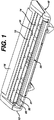
図1は本発明により形成されたシェービング器具に使用されるかみそり刃組立体を示す正面から見た斜視図である。
図2は図1の構体の各種素子を示す正面から見た分解図である。
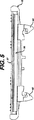
図3は図1の構体の選択した素子を取り除いた図1と同様な正面から見た斜視図である。
図4は図3の構体の詳細を示す平面図である。
図5は図3と4の構体の更に詳細を示す正面図である。
図6は図1から図5の構体のプラットホーム素子を示す平面図である。
図7は図6の線VII-VIIに沿う正面から見た断面図である。
図8は図4の線VIII-VIIIに沿う横から見た拡大断面図である。
図9は明瞭にするため拡大して示す図8の構体の一部の断面図である。
図10は図4の線X-Xに沿う横から見た拡大断面図である。
図1、図2に示すように、かみそり刃組立体10は一対の刃13,14を支持する細長いプラットホーム12を備えており、そのプラットホーム12は互いに離間するスペーサ16を有している。キャップ部材18には4本の円筒形リベット20,21,22,23が設けられており、それらはプラットホーム12に組み込まれたとき刃13,14及びスペーサ16の複数の円形開口24を介して延び、且つプラットホーム12に形成された円形穴26,27,28,29に受け入れられる。
上方に突出するフィン31,32,33を有するガード部材30がプラットホーム12の前縁に配設されている。ガード部材30はプラットホーム12上に位置するように形成されており、その対面または下面に設けられている部分34,35,36と、プラットホーム12に設けられた溝44内に形成された部分37を有する。プラットホーム12に直接モールドされているガード部材30は、部分34,35,36がプラットホームの開口を介してモールドされており、ガード部材がプラットホームから除去されればガード部材から切り離されるので、図2に示すように分離した状態には表れない。図2のガード部材30はかみそり刃組立体10の各部品の詳細を示すため、別個のユニットとして表わしてある。
更にガード部材30は、ここでは一対の静止刃13,14を有するかみそり構体の一部分に形成されているが、ここで言うガード部材は、かみそり構体又はカートリッジのいずれにも採用され、且つ一枚刃、複数の刃又は前述のアプリル他(Apprille Jr. et al.,)の米国特許第5,249,361号に示した可動刃の組み合わせにも採用される。
図3乃至図10に示すように、図1,2に示すかみそり刃構体10に組み込まれるプラットホーム12は、刃13,14を支持するため必要な強度を付与するためポリプロピレン材料から製造される。プラットホームにはプラットホームの前縁に隣接する面39から上方に延びる複数の長方形のウェブ38が設けられており、且つ複数の穴40がウェブ38間に面39を貫通するように形成され、その穴40はプラットホーム12の下方に開口されている。ガード部材30のエラストマー材料の部分はウェブ38を取り囲む。
本実施の形態のプラットホーム12は、かみそり刃構体を柄(図示せず)に組み立てるために設けられる一対の取り付け部材42,43を備える。適切な柄に対するかみそり刃構体10の組立については記載しないが、かかる柄及び取り付け方法は当業者において周知であり、多くの形態を採用でき、本発明の主要部ではない。
かみそり刃組立体10にプラットホーム12を組み立てるのに先立ち、細長いガード部材30は、適切な型及び個々で記載する構成が達成できるような周知の型の射出成形機(図示せず)を準備することによりプラットホームに射出成型できる。
細長いガード部材30は、全般的に成型プロセス中皮膚に好ましい触感を与える立ち上がったリブ即ちフィン31,32,33に可撓性を提供するように選ばれた、熱可塑性エラストマー材料からなる。かかる可撓性を得るため選ばれた材料は全般的にショアAスケールで27−75の範囲の硬度を有しており、選択された材料は、シェル会社(Shell Corporation)で製造されたショアAスケールで硬度55を有するクレートン(Kraton)G2705、ショアA硬度27のエボプレン(Evoprene)#966及びアドバンスドエラストマー会社(Advanced Elastomerics Corporation)から売り出されマサチュセッツ州レオミンスターのグレイケミカル会社(Gray Chemical Corporation)で販売されているショアA硬度55のサントプレン(Santoprene)271-55やショアA硬度73のサントプレン271-73である。
細長いガード部材30は所望の構成を得るため適切な方法で射出成型され、本実施の形態では、この目的のために設けられた溝44を介してプラットホーム12の後部で射出成型が行われる。材料が溝44を介して流れたとき、部分37が溝に成型され、且つ材料はフィン31,32,33を作るため型内に保留され、図2に示すように穴40を介して下方に、且つプラットホーム12の下面に細長い部分34,35,36を形成する長方形のウェブ38の周囲に延びる。これによりより強固なプラットホーム12に可撓性材料を固定し、プラットホームの下の固定位置にガード部材30を保留できる。更に2個プラスチック間の化学的親和性は接着力を支援する。このような処理は同様な型の室に2段成型を容易にでき、次いでプラットホーム12とガード部材30の形成された全体の最終組立体を取り除くことができる。
本実施の形態においては、かみそり刃構体10は適切な柄(図示せず)に取り付けられたとき、柄の周囲に回転できることを意図している。しかしながらこの特徴がないときでもシェービングプロセス中かみそり刃組立体は僅かに回転する。従ってフィン31,32,33が、シェービング動作中皮膚上のかみそり構体の滑らかな移動を増加するため、プラットホーム12の前方縁で半径方向面に合致することが非常に望まれる。ガード部材30が単一の一体の素子の場合には、プラットホーム12の構体にガード部材を成型するのに多くの自由度がある。
図9に明瞭に示すように、本実施の形態による細長いガード部材30はそれよりフィン31,32,33が上方に延びる半径方向面49を有するベース部分48を得るようにモールドされる。フィン31,32,33は互いに離間し、且つ各フィンの最上面は後方に配置されたフィンの最上面より下方にある。各フィン31,32,33のそれぞれに適切な可撓性と強度を与えるため、各フィンはベース部分では最大の厚み、最上面では最小の厚みを持つようにテーパづけられている。
図9,図10に示すように、フィン31,32,33は凸形状の弧状面に沿って配設されたベース部分48から遠ざかって設けられた末端を有する。フィンの末端は個々の末端によって決められた接触面の合計より大きい面積にわたるガード面を形成しているが(即ちフィンの末端によって決められる面と、該面より大きい末端間のスペースが、それ自体フィンの末端である)、フィン31,32,33のスペースは比較的密接しているので、皮膚に感ずる感触は全般的に連続面となる。フィンの可撓性とフィンのエラストマー材料の摩擦係数はプラットホーム材料より大きいので、皮膚に好ましい引っ張り力を提供することになる。フィンの配置が、皮膚面をシェービングするときの移動方向と全般的に垂直であるので、即ちシェービングのパスは刃縁に全般的に平行であるので、シェービングの引っ張り力は皮膚に対し好都合に働く。
再び図9について説明すると、順次より後方、即ち刃13,14に向かう方向に置かれている各フィン31,32,33は、前方に置かれた隣接するフィンより垂直方向から遠ざかるように即ち刃の方向に傾斜している。図9においてフィン33の前縁側面33aはほぼ垂直で後方の傾斜角度Aは約1°、フィン32の前縁側面32aは後方に約5°の角度B傾斜し、フィン33の前縁側面33aは後方に約15°の角度C傾斜している。フィン31,32,33のこの配置は斜めに広がる又はかき戻す状態と見なされ、同じベース部分48で皮膚接触面にフィンが単に垂直の場合より、そして主刃14の露出を阻止することになる主刃14に接近して多数のフィンを加える必要なく、好都合な空間的な覆いを提供することになり、この結果僅かの材料で、刃の露出を阻止することなく良好な引っ張り力を提供できる。斜めに広がる状態はモールドされたカートリッジやガードをそのままで射出成形ツールからの放出を助けることになる。図9に示すように、各前縁側面31a,32a,33aと反対側の後縁フィン側面31b,32b,33bは、各フィンの可撓性に影響する各前縁側面の傾斜角から異なる、上方に向く垂直軸から離れる傾斜角度で各フィンを二分する中央面に向けて傾斜する。
図8、図10に示すように、前記引用した米国特許第5,249,361号の図6の組立体に比較して、ガード部材30と前方のフィン33はプラットホーム12に覆い被ったり、より前に延びたりすることはないので、フィン面の前方の高抵抗状態のプラットホームからフィンの引き剥がし又は分離に対し、更にシェービングされる皮膚例えば顔にあまりにも平坦に向けるというユーザーの気遣いを低減することができる。斜めに広がる後方フィンにより形成される全般的に凸状即ち弧状面に沿うフィン31,32,33の末端の配置により、、もしすべてのフィンが板状の平坦面に終っているときに起こるような、皮膚面に対しカートリッジをを平らに押すことなく、例えば顔のような体の曲がった皮膚面に自然に適合でき、更にユーザーがカートリッジのシェービング動作を適切に方向付けるメッセージとして皮膚面への十分な指示を提供できる。かかる順次斜めに広がる状態のエラストマー状のフィン31,32,33は、僅かな実際の作業範囲内で高摩擦引っ張り力を提供でき、且つユーザーが板状のフィンチップ面より快適に、シェービングされる面にカートリッジを向けることができる。
図3,4,5に示すプラットホーム12にモールドされた細長いガード部材30により、刃13,14、スペーサ16及びキャップ部材18は、図2に示すかみそり刃組立体10を製造するために組立てられる。かみそり刃組立体10は、ほぼ可撓性熱可塑性材料のガード部材30と、ほぼ強固なプラスチック材料のプラットーム12とを具備し、プラットホームは刃13,14を支持でき、かみそり構成を完成するため柄に強固に取り付けできる。The present invention relates to a razor blade assembly, and more particularly to a guard used to couple one or more blades to a razor or razor cartridge.
U.S. Pat. No. 3,724,070 to Francis W. Dorin Jr., issued April 3, 1973, is designed to engage the shaved surfaces before and after the cutting part of the blade device, respectively. A blade assembly is disclosed in which a blade device is held between blade assembly surfaces. Such surfaces are generally referred to as “guard” and “cap” surfaces in the prior art.
Various combinations of guards, caps and blade devices are disclosed in the prior art. A typical combination is disclosed in US Pat. No. 4,168,571 to Jone F. Francis, issued September 25, 1979, in which the guard, cap and blade device can move independently of each other. It has been shown. In addition, Chester F. Jacobson, US Patent No. 4,270,268, issued June 2, 1981, and Alan Crook, US Patent Application No. 659,430, filed March 21, 1991. There is. Other disclosures of such combinations are disclosed in U.S. Pat. Nos. 4,270,268; 4,488,357; 4,492,024; 4,492,024; 4,498,235; 4,551,916; 4,573,266, all issued in the name of Chester F. Jacobson and assigned to the same assignee as the present application. 4,586,255; 4,378,634; 4,587,729 and 4,621,424.
US Pat. No. 5,249,361 issued to Domenic V. Apprille Jr. et al., Issued on October 5, 1993 and assigned to the same assignee as this application. It is disclosed to have a guard member assembled in front of the above blades and extending in parallel. The guard is a two-part mold assembly having an upper portion of an elastomeric material having a plurality of upward protrusions and a lower base portion of a rigid plastic material, preferably polypropylene. The lower base portion of the strong plastic material has a pair of projecting elements separated from each other to form a V-shaped cross-sectional portion projecting downward and a hole spaced apart from the blade cartridge and receiving the V-shaped base portion. Have A two-part guard with an elastomeric material top and a strong plastic material base is marketed by the assignee of the present application under the trade name “Sensor Excel” and accepted by customers for commercial success. It has been proven that
As disclosed in U.S. Pat. No. 5,249,361 described above, the guard member is assembled together prior to incorporation into a razor blade assembly which requires a separate process to produce the guard member prior to placement in the razor blade assembly. Manufactured from two separate components. In addition, the final bond between the elastomeric material portion and the rigid plastic material base portion has a greater longitudinal width dimension than a single elastomeric material unit loaded directly into the razor blade assembly. The configuration of the upwardly protruding protrusion and the position relative to each other and with respect to the plurality of blades is more stringent than in the case of a guard member made as an integral element supported by the razor blade assembly.
An object of the present invention is to provide a razor blade assembly having a guard member that is molded into a support structure while the guard member is left as it is.
Another object of the present invention is to provide a base portion and a leading edge of a razor blade assembly comprising a plurality of spaced apart fins, each fin being below the top surface of the fin, the top surface of which is located behind. It is to provide an elongated guard member provided adjacently.
Yet another object of the present invention is to provide a base portion and a leading edge of a razor blade assembly comprising a plurality of spaced apart fins, each fin being inclined more backward relative to the main blade than the front fin. To provide an elongated guard member provided adjacently.
Still another object of the present invention is to provide a guard member that can be easily assembled to a razor blade assembly.
Still another object of the present invention is to provide a razor blade assembly that is simple in construction and can be manufactured economically.
It is yet another object of the present invention to provide a method of manufacturing a razor blade assembly in which a guard member is simply formed into a plurality of desired configurations.
The foregoing and other objects will become apparent in the following description, but can be achieved by providing a razor blade assembly having an elongated platform and at least one blade member disposed on the platform.
The platform is generally made of a strong plastic material, while the elongated guard member is generally made of an elastomeric material. The elastomeric material has a hardness in the range of 27-75 as measured on the Shore A hardness scale, and the platform has a plurality of openings through the guard member that is molded to maintain the guard member interlocking with the platform. I have.
The elongate guard member is formed adjacent to the front edge of the elongate platform and includes a base portion having a plurality of fins, each fin being spaced from each other and the uppermost surface being below the uppermost surface of the fin disposed rearwardly. To do.
The base portion of the guard member generally forms a generally arcuate surface from which the fin extends, and the fin is tapered to have a maximum thickness at the base portion and a minimum thickness at the top surface.
The novel features and advantages of the present invention will be described with reference to the accompanying drawings showing embodiments of the present invention.
FIG. 1 is a front perspective view showing a razor blade assembly used in a shaving device formed according to the present invention.
2 is an exploded view seen from the front showing various elements of the structure of FIG.
FIG. 3 is a front perspective view similar to FIG. 1 with the selected elements of the structure of FIG. 1 removed.
FIG. 4 is a plan view showing details of the structure of FIG.
FIG. 5 is a front view showing further details of the structure of FIGS.
FIG. 6 is a plan view showing the platform element of the structure shown in FIGS.
7 is a cross-sectional view seen from the front along the line VII-VII in FIG.
8 is an enlarged cross-sectional view seen from the side along the line VIII-VIII in FIG.
9 is a partial cross-sectional view of the structure of FIG. 8 shown enlarged for clarity.
FIG. 10 is an enlarged cross-sectional view seen from the side along the line XX in FIG.
As shown in FIGS. 1 and 2, the
A
Further, the
As shown in FIGS. 3-10, the
The
Prior to assembling the
The
The
In the present embodiment, the
As clearly shown in FIG. 9, the
As shown in FIGS. 9 and 10, the
Referring again to FIG. 9, each
As shown in FIGS. 8 and 10, the
Claims (8)
上記プラットホームに配設され、且つカッティングパスを決める前方にほぼ方向付けられたカッティング縁を有する少なくとも一枚の刃部材と、
前記第1のプラスチック材料よりも可撓性を有する第2のプラスチック材料からなり、上記プラットホームの前縁に隣接して配設され、且つ刃部材のカッティング縁の前方に離間し、複数のフィンが設けられたベース部分を有する細長いガード部材とを有し、
上記各フィンは、上記ベース部分から上方に且つカッティングパスに垂直に延びており、各フィンは互いに離間し、該フィンの最上面とベース部分との間の距離は後方に配設されたフィンの最上面とベース部分との間の距離より小さく、複数のフィンのそれぞれの最上面を連ねる線が全体的に外方凸形状の弧状面を形成し、これによりかみそり刃組立体によるシェービング中、皮膚に対する刃部材の方向が変わる時ユーザーの皮膚に連続する引っ張り力が加えられる、かみそり刃組立体。An elongated platform made of a first plastic material;
At least one blade member disposed on the platform and having a cutting edge oriented generally forward to define a cutting path;
A second plastic material that is more flexible than the first plastic material, disposed adjacent to the front edge of the platform and spaced apart in front of the cutting edge of the blade member; An elongated guard member having a provided base portion;
The fins extend upward from the base portion and perpendicular to the cutting path , the fins are spaced apart from each other, and the distance between the uppermost surface of the fin and the base portion is that of a fin disposed behind. A line that is smaller than the distance between the uppermost surface and the base portion and connects the uppermost surfaces of the plurality of fins forms an arcuate surface that is generally outwardly convex, whereby the skin is shaved during shaving by the razor blade assembly. A razor blade assembly in which a continuous pulling force is applied to the user's skin when the orientation of the blade member relative to is changed.
該少なくとも1枚の刃を支持し、刃先と平行に延びる前方壁を持ち且つ少なくとも1枚の刃の前方に配設されたかみそり刃本体構体と、
シェービング中少なくとも1枚の刃の前方でシェービングされる皮膚と接触し広げるためかみそり刃本体構体に配設され、エラストマー材料の一体のモールド部材からなるガード部材と
からなる安全かみそり刃ユニットであって、
前記一体のモールド部材は、ガード部材の長手方向に沿うかみそり刃本体構体の前方壁に隣接して並置するため下方に延びるモールドされた底部ベース部分と、少なくとも1枚の刃が当てられる皮膚面と接触するため底部ベース部分から突出する複数の突起を有するモールドされた上方部分とからなり、
前記突起は刃先に平行の前記ガード上方部分の上面に沿って延び、互いに離間する少なくとも3本のフィンを有し、前記各離間したフィンは弧状の凸形状の面に配設された末端をそれぞれ有し、引き続く前記フィンは前記少なくとも1枚の刃に対し前方に配設された隣接フィンより傾斜し、ガード部材は、個々のフィンの末端の接触面の合計面積より大きい面積である当該ガード部材における一連の接触面で、シェービングされるべき皮膚に係合する、安全かみそり刃ユニット。At least one blade,
A razor blade body assembly that supports the at least one blade, has a front wall extending parallel to the blade edge, and is disposed in front of the at least one blade;
A safety razor blade unit comprising a guard member made of an integral molding member made of an elastomer material, arranged in a razor blade body structure for contacting and spreading the skin to be shaved in front of at least one blade during shaving,
The integral mold member includes a molded bottom base portion extending downwardly for juxtaposition adjacent to the front wall of the razor blade body structure along the longitudinal direction of the guard member, and a skin surface to which at least one blade is applied. A molded upper portion having a plurality of protrusions protruding from the bottom base portion for contact;
The protrusions extend along the upper surface of the upper part of the guard parallel to the blade edge, and have at least three fins that are spaced apart from each other. Each of the spaced fins has a distal end disposed on an arcuate convex surface. The succeeding fin is inclined with respect to the adjacent fin disposed forward with respect to the at least one blade, and the guard member has an area larger than the total area of the contact surfaces at the ends of the individual fins. A safety razor blade unit that engages the skin to be shaved with a series of contact surfaces in.
Applications Claiming Priority (3)
| Application Number | Priority Date | Filing Date | Title |
|---|---|---|---|
| US08/854,573 US5794343A (en) | 1997-05-12 | 1997-05-12 | Razor blade assembly |
| US08/854,573 | 1997-05-12 | ||
| PCT/US1998/008410 WO1998051457A2 (en) | 1997-05-12 | 1998-04-27 | Razor assembly |
Publications (3)
| Publication Number | Publication Date |
|---|---|
| JP2001524860A JP2001524860A (en) | 2001-12-04 |
| JP2001524860A5 JP2001524860A5 (en) | 2005-10-06 |
| JP4642163B2 true JP4642163B2 (en) | 2011-03-02 |
Family
ID=25319072
Family Applications (1)
| Application Number | Title | Priority Date | Filing Date |
|---|---|---|---|
| JP54924998A Expired - Fee Related JP4642163B2 (en) | 1997-05-12 | 1998-04-27 | Razor assembly |
Country Status (18)
| Country | Link |
|---|---|
| US (1) | US5794343A (en) |
| EP (2) | EP0981425B1 (en) |
| JP (1) | JP4642163B2 (en) |
| KR (2) | KR100557834B1 (en) |
| CN (2) | CN1234513C (en) |
| AR (1) | AR015118A1 (en) |
| AT (2) | ATE214324T1 (en) |
| AU (1) | AU726850B2 (en) |
| BR (1) | BR9808779A (en) |
| CA (1) | CA2288101C (en) |
| DE (2) | DE69811743T2 (en) |
| ES (2) | ES2188570T3 (en) |
| HK (1) | HK1024884A1 (en) |
| HU (2) | HU0200478D0 (en) |
| NO (2) | NO995519L (en) |
| PL (1) | PL186836B1 (en) |
| RU (1) | RU2183156C2 (en) |
| WO (1) | WO1998051457A2 (en) |
Families Citing this family (60)
| Publication number | Priority date | Publication date | Assignee | Title |
|---|---|---|---|---|
| WO1999014020A1 (en) * | 1997-09-18 | 1999-03-25 | The Gillette Company | Safety razors |
| US6167625B1 (en) * | 1999-05-18 | 2001-01-02 | Warner-Lambert Company | Shaving implement |
| US6675479B1 (en) * | 2000-02-29 | 2004-01-13 | The Gillette Company | Shaving razor and blade unit with improved guard |
| US6651342B1 (en) | 2000-02-29 | 2003-11-25 | The Gillette Company | Shaving razor and blade unit with improved guard |
| US6550141B1 (en) * | 2000-07-28 | 2003-04-22 | Warner-Lambert Company | Razor heads with intermediate guard elements |
| US20020095791A1 (en) * | 2001-01-23 | 2002-07-25 | Pennella Andrew J. | Razor blade cartridge having guard ribs and methods therefor |
| US20040103538A1 (en) * | 2002-08-21 | 2004-06-03 | Eveready Battery Company, Inc. | Razor cartridge |
| JP3931881B2 (en) * | 2003-12-08 | 2007-06-20 | フェザー安全剃刀株式会社 | Razor with protective member |
| DE602004017652D1 (en) * | 2004-05-06 | 2008-12-18 | Bic Violex Sa | SHAVING HEAD WITH SEPARATED FIXED PARTS AND MANUFACTURING METHOD THEREFOR |
| DE602005026979D1 (en) * | 2004-10-05 | 2011-04-28 | Eveready Battery Inc | SHAVER |
| US7748121B2 (en) | 2005-05-06 | 2010-07-06 | Eveready Battery Company, Inc. | Razor blade and support assembly |
| US8186062B2 (en) * | 2007-03-19 | 2012-05-29 | Eveready Battery Company, Inc. | Safety razor with filament guard |
| US20080256800A1 (en) * | 2007-04-20 | 2008-10-23 | Roy Nicoll | Razor cartridge assembly with movable face |
| US20090083982A1 (en) * | 2007-09-28 | 2009-04-02 | The Gillette Company | Decreasing blade spans |
| US20100319198A1 (en) * | 2009-06-17 | 2010-12-23 | Robert Harold Johnson | Blade cartridge guard comprising an array of flexible fins having varying stiffness |
| US20110119923A1 (en) * | 2009-11-20 | 2011-05-26 | Roy Nicoll | Razors and kits for applying shaving aids |
| JP5527762B2 (en) * | 2010-02-04 | 2014-06-25 | 株式会社貝印刃物開発センター | Razor head |
| US8813371B2 (en) * | 2010-05-04 | 2014-08-26 | Vancouver Tool Corporation | Blade protector for cutting tools |
| USD633253S1 (en) | 2010-06-23 | 2011-02-22 | American Safety Razor | Razor cartridge |
| USD640415S1 (en) | 2010-07-07 | 2011-06-21 | American Safety Razor | Razor cartridge |
| USD648075S1 (en) | 2010-07-07 | 2011-11-01 | American Safety Razor | Razor cartridge |
| USD643977S1 (en) | 2010-10-19 | 2011-08-23 | American Safety Razor | Razor cartridge |
| USD643976S1 (en) | 2010-10-19 | 2011-08-23 | American Safety Razor | Razor cartridge |
| US9492933B2 (en) * | 2011-09-30 | 2016-11-15 | The Gillette Company | Guard for a shaving razor |
| JP2014534025A (en) * | 2011-10-25 | 2014-12-18 | エバレデイ バツテリ カンパニー インコーポレーテツド | Razor cartridge with improved guard |
| US20140026424A1 (en) * | 2012-07-24 | 2014-01-30 | The Gillette Company | Razor cartridge |
| US9802328B2 (en) * | 2013-11-13 | 2017-10-31 | The Gillette Company Llc | Razor cartridge guard structure |
| PL3083163T3 (en) * | 2013-12-18 | 2020-06-01 | Bic-Violex S.A. | A shaving blade cartridge |
| US9636830B2 (en) * | 2014-01-14 | 2017-05-02 | The Gillette Company Llc | Heated shaving razors |
| BR112016024696B1 (en) * | 2014-04-24 | 2021-01-05 | Shavelogic, Inc. | shaving cartridge |
| WO2017103881A1 (en) * | 2015-12-17 | 2017-06-22 | Bic Violex S.A. | Shaving head |
| BR112018068899A2 (en) | 2016-03-18 | 2019-01-22 | Personal Care Marketing And Res Inc | razor blade cartridge |
| US10652956B2 (en) | 2016-06-22 | 2020-05-12 | The Gillette Company Llc | Personal consumer product with thermal control circuitry and methods thereof |
| EP3351358B1 (en) | 2017-01-20 | 2019-11-20 | The Gillette Company LLC | Heating delivery element for a shaving razor |
| CN110267780B (en) * | 2017-06-26 | 2022-03-04 | 苏泊玛私人护理有限公司 | Razor cartridge with enhanced rinsability |
| ZAA201801244S (en) * | 2018-02-24 | 2019-05-29 | Super Max Personal Care Pvt Ltd | Cartridge base for safety razor |
| ZAA201801243S (en) * | 2018-02-24 | 2019-05-29 | Super Max Personal Care Pvt Ltd | Cartridge for safety razor |
| ZAA201801245S (en) * | 2018-02-24 | 2019-05-29 | Super Max Personal Care Pvt Ltd | Cap for cartridge of safety razor |
| USD874061S1 (en) | 2018-03-30 | 2020-01-28 | The Gillette Company Llc | Shaving razor cartridge |
| JP2021517043A (en) | 2018-03-30 | 2021-07-15 | ザ ジレット カンパニー リミテッド ライアビリティ カンパニーThe Gillette Company Llc | Razor handle with pivot part |
| US11607820B2 (en) | 2018-03-30 | 2023-03-21 | The Gillette Company Llc | Razor handle with movable members |
| JP2021515616A (en) | 2018-03-30 | 2021-06-24 | ザ ジレット カンパニー リミテッド ライアビリティ カンパニーThe Gillette Company Llc | Shaving razor cartridge and manufacturing method |
| EP3774226B1 (en) | 2018-03-30 | 2022-04-06 | The Gillette Company LLC | Shaving razor cartridge and method of manufacture |
| US11826924B2 (en) | 2018-03-30 | 2023-11-28 | The Gillette Company Llc | Shaving razor cartridge and method of manufacture |
| EP3705245B1 (en) | 2018-03-30 | 2021-12-15 | The Gillette Company LLC | Shaving razor handle |
| JP7090727B2 (en) | 2018-03-30 | 2022-06-24 | ザ ジレット カンパニー リミテッド ライアビリティ カンパニー | Razor handle with pivot part |
| US11123888B2 (en) | 2018-03-30 | 2021-09-21 | The Gillette Company Llc | Razor handle with a pivoting portion |
| CN111819050B (en) | 2018-03-30 | 2022-10-04 | 吉列有限责任公司 | Razor handle with movable member |
| EP3774224A1 (en) | 2018-03-30 | 2021-02-17 | The Gillette Company LLC | Razor handle with a pivoting portion |
| BR112020020123A2 (en) | 2018-03-30 | 2021-01-26 | The Gillette Company Llc | shaver or shaving handle with a pivoting portion |
| JP2021516136A (en) | 2018-03-30 | 2021-07-01 | ザ ジレット カンパニー リミテッド ライアビリティ カンパニーThe Gillette Company Llc | Razor handle with movable members |
| USD884970S1 (en) | 2019-02-27 | 2020-05-19 | PCMR International Ltd. | Razor cartridge guard |
| USD884969S1 (en) | 2019-02-27 | 2020-05-19 | Pcmr International Ltd | Combined razor cartridge guard and docking |
| USD884971S1 (en) | 2019-02-27 | 2020-05-19 | Pcmr International Ltd | Razor cartridge |
| AU2020253440B2 (en) * | 2019-04-04 | 2023-09-14 | The Gillette Company Llc | Razor cartridge |
| USD926374S1 (en) | 2019-04-04 | 2021-07-27 | The Gillette Company Llc | Shaving razor cartridge cover |
| KR102350037B1 (en) * | 2019-12-10 | 2022-01-11 | 주식회사 도루코 | Razor Cartridge |
| USD1016392S1 (en) | 2020-09-24 | 2024-02-27 | The Gillette Company Llc | Shaving razor cartridge |
| US11000960B1 (en) | 2020-11-16 | 2021-05-11 | Personal Care Marketing And Research, Inc. | Razor exposure |
| USD980525S1 (en) | 2021-04-05 | 2023-03-07 | Edgewell Personal Care Brands, Llc | Razor cartridge housing |
Family Cites Families (30)
| Publication number | Priority date | Publication date | Assignee | Title |
|---|---|---|---|---|
| US1497647A (en) * | 1921-04-05 | 1924-06-10 | Frank E Smith | Razor attachment |
| DE385938C (en) * | 1922-11-28 | 1923-12-14 | Albert Nuernberg | Rock drill |
| US3138865A (en) * | 1960-08-13 | 1964-06-30 | Meyer Eugen | Safety razor having skin-stretching and guiding means |
| US3724070A (en) | 1971-03-15 | 1973-04-03 | Gillette Co | Dual razor blade assembly |
| US3722090A (en) * | 1971-08-12 | 1973-03-27 | Warner Lambert Co | Guard bar for safety razors |
| GB1557177A (en) * | 1975-09-12 | 1979-12-05 | Wilkinson Sword Ltd | Shaving units |
| GB1566505A (en) | 1977-02-02 | 1980-04-30 | Gillette Co | Safety razor |
| US4270268A (en) | 1979-12-07 | 1981-06-02 | The Gillette Company | Razor blade assembly |
| GB2108033B (en) * | 1981-10-13 | 1985-05-01 | Gillette Co | Safety razors |
| US4488357A (en) | 1982-09-17 | 1984-12-18 | The Gillette Company | Safety razor |
| US4498235A (en) | 1982-09-17 | 1985-02-12 | The Gillette Company | Razor blade assembly |
| US4492025A (en) | 1982-09-17 | 1985-01-08 | The Gillette Company | Razor handle assembly |
| US4492024A (en) | 1982-09-17 | 1985-01-08 | The Gillette Company | Razor blade assembly |
| US4852254A (en) * | 1984-09-20 | 1989-08-01 | Wilkinson Sword Limited | Razor blade assembly and its method of manufacture |
| US5141694A (en) * | 1987-04-24 | 1992-08-25 | Warner-Lambert Company | Process for insert molding wet-shaving razor unit |
| US4949457A (en) * | 1988-08-03 | 1990-08-21 | Warner-Lambert Company | Soft resilient razor handle |
| US5191712A (en) * | 1988-10-28 | 1993-03-09 | The Gillette Company | Safety razors and guards |
| GB8825268D0 (en) * | 1988-10-28 | 1988-11-30 | Gillette Co | Safety razors |
| US5067238A (en) * | 1990-09-28 | 1991-11-26 | The Gillette Company | Shaving system |
| GB9106860D0 (en) * | 1991-04-02 | 1991-05-22 | Gillette Co | Safety razor |
| US5249361A (en) * | 1992-05-13 | 1993-10-05 | The Gillette Company | Guard for razor blade assembly |
| JPH0654966A (en) * | 1992-08-06 | 1994-03-01 | Kaijirushi Hamono Kaihatsu Center:Kk | Shaver |
| US5331740A (en) * | 1992-10-08 | 1994-07-26 | The Gillette Company | Shaving system |
| US5416973A (en) * | 1993-09-30 | 1995-05-23 | The Gillette Company | Razors |
| DE4405764A1 (en) * | 1994-02-23 | 1995-08-24 | Braun Ag | Personal utensil housing wall |
| US5546660A (en) * | 1994-09-30 | 1996-08-20 | Warner-Lambert Company | Dynamic razor head |
| CN1065808C (en) * | 1995-02-23 | 2001-05-16 | 松下电工株式会社 | Dry-type razor with skin-tightening device |
| US5666729A (en) * | 1995-04-10 | 1997-09-16 | Warner-Lambert Company | Suspended blade shaving system |
| US5689883A (en) * | 1995-05-08 | 1997-11-25 | Warner-Lambert Company | Shaving implement |
| US5661907A (en) * | 1996-04-10 | 1997-09-02 | The Gillette Company | Razor blade assembly |
-
1997
- 1997-05-12 US US08/854,573 patent/US5794343A/en not_active Expired - Lifetime
-
1998
- 1998-04-27 AT AT98918766T patent/ATE214324T1/en not_active IP Right Cessation
- 1998-04-27 DE DE69811743T patent/DE69811743T2/en not_active Expired - Lifetime
- 1998-04-27 CN CNB021598134A patent/CN1234513C/en not_active Expired - Lifetime
- 1998-04-27 RU RU99126434/12A patent/RU2183156C2/en not_active IP Right Cessation
- 1998-04-27 AU AU71630/98A patent/AU726850B2/en not_active Ceased
- 1998-04-27 AT AT01102526T patent/ATE233153T1/en not_active IP Right Cessation
- 1998-04-27 PL PL98336789A patent/PL186836B1/en not_active IP Right Cessation
- 1998-04-27 ES ES01102526T patent/ES2188570T3/en not_active Expired - Lifetime
- 1998-04-27 ES ES98918766T patent/ES2170490T3/en not_active Expired - Lifetime
- 1998-04-27 CA CA002288101A patent/CA2288101C/en not_active Expired - Fee Related
- 1998-04-27 JP JP54924998A patent/JP4642163B2/en not_active Expired - Fee Related
- 1998-04-27 KR KR1019997010390A patent/KR100557834B1/en not_active IP Right Cessation
- 1998-04-27 EP EP98918766A patent/EP0981425B1/en not_active Expired - Lifetime
- 1998-04-27 DE DE69804210T patent/DE69804210T2/en not_active Expired - Lifetime
- 1998-04-27 KR KR1020057016360A patent/KR100539660B1/en not_active IP Right Cessation
- 1998-04-27 HU HU0200478A patent/HU0200478D0/en unknown
- 1998-04-27 EP EP01102526A patent/EP1097788B1/en not_active Expired - Lifetime
- 1998-04-27 CN CN98805034A patent/CN1126650C/en not_active Expired - Lifetime
- 1998-04-27 HU HU0003400A patent/HU223398B1/en not_active IP Right Cessation
- 1998-04-27 BR BR9808779-7A patent/BR9808779A/en not_active IP Right Cessation
- 1998-04-27 WO PCT/US1998/008410 patent/WO1998051457A2/en active IP Right Grant
- 1998-05-11 AR ARP980102169A patent/AR015118A1/en active IP Right Grant
-
1999
- 1999-11-11 NO NO995519A patent/NO995519L/en not_active Application Discontinuation
-
2000
- 2000-05-12 HK HK00102851A patent/HK1024884A1/en not_active IP Right Cessation
-
2008
- 2008-02-04 NO NO20080625A patent/NO20080625L/en not_active Application Discontinuation
Also Published As
Similar Documents
| Publication | Publication Date | Title |
|---|---|---|
| JP4642163B2 (en) | Razor assembly | |
| AU749061B2 (en) | Razor head with moveable blade package | |
| AU648296B2 (en) | Flexible razor head | |
| KR100283849B1 (en) | Razor handle assembly | |
| EP1937444B1 (en) | Blade mounting members for a razor cartridge | |
| US5249361A (en) | Guard for razor blade assembly | |
| US5461781A (en) | Dynamic shaving system with integral push clean bar and spring member | |
| US7810240B2 (en) | Shaving razors and other hair cutting assemblies | |
| JP5405503B2 (en) | Shaving razor with additional trim blade | |
| CN114174023A (en) | Razor cartridge | |
| US20060032056A1 (en) | Bidirectional shaving cartridge and razor including same | |
| MXPA97002663A (en) | Assembly of handle for afei penknife | |
| JP3588361B2 (en) | Cleaning device for flexible razor unit for wet shaving | |
| MXPA99010328A (en) | Razor assembly | |
| WO1996004111A1 (en) | Razor head with enhanced skin protection | |
| CZ9903798A3 (en) | Razor blade of a shaver | |
| MXPA94005841A (en) | Movable blade shaving cartridge or the like | |
| JP2011104392A (en) | Shaving razor blade unit |
Legal Events
| Date | Code | Title | Description |
|---|---|---|---|
| A521 | Request for written amendment filed |
Free format text: JAPANESE INTERMEDIATE CODE: A523 Effective date: 20050207 |
|
| A621 | Written request for application examination |
Free format text: JAPANESE INTERMEDIATE CODE: A621 Effective date: 20050207 |
|
| A131 | Notification of reasons for refusal |
Free format text: JAPANESE INTERMEDIATE CODE: A131 Effective date: 20071113 |
|
| A601 | Written request for extension of time |
Free format text: JAPANESE INTERMEDIATE CODE: A601 Effective date: 20080129 |
|
| A602 | Written permission of extension of time |
Free format text: JAPANESE INTERMEDIATE CODE: A602 Effective date: 20080310 |
|
| A521 | Request for written amendment filed |
Free format text: JAPANESE INTERMEDIATE CODE: A523 Effective date: 20080509 |
|
| A131 | Notification of reasons for refusal |
Free format text: JAPANESE INTERMEDIATE CODE: A131 Effective date: 20081118 |
|
| A601 | Written request for extension of time |
Free format text: JAPANESE INTERMEDIATE CODE: A601 Effective date: 20090209 |
|
| A602 | Written permission of extension of time |
Free format text: JAPANESE INTERMEDIATE CODE: A602 Effective date: 20090323 |
|
| A521 | Request for written amendment filed |
Free format text: JAPANESE INTERMEDIATE CODE: A523 Effective date: 20090430 |
|
| A131 | Notification of reasons for refusal |
Free format text: JAPANESE INTERMEDIATE CODE: A131 Effective date: 20090623 |
|
| A601 | Written request for extension of time |
Free format text: JAPANESE INTERMEDIATE CODE: A601 Effective date: 20090916 |
|
| A602 | Written permission of extension of time |
Free format text: JAPANESE INTERMEDIATE CODE: A602 Effective date: 20091102 |
|
| A131 | Notification of reasons for refusal |
Free format text: JAPANESE INTERMEDIATE CODE: A131 Effective date: 20100323 |
|
| A601 | Written request for extension of time |
Free format text: JAPANESE INTERMEDIATE CODE: A601 Effective date: 20100622 |
|
| A602 | Written permission of extension of time |
Free format text: JAPANESE INTERMEDIATE CODE: A602 Effective date: 20100802 |
|
| A521 | Request for written amendment filed |
Free format text: JAPANESE INTERMEDIATE CODE: A523 Effective date: 20100914 |
|
| TRDD | Decision of grant or rejection written | ||
| A01 | Written decision to grant a patent or to grant a registration (utility model) |
Free format text: JAPANESE INTERMEDIATE CODE: A01 Effective date: 20101102 |
|
| A01 | Written decision to grant a patent or to grant a registration (utility model) |
Free format text: JAPANESE INTERMEDIATE CODE: A01 |
|
| A61 | First payment of annual fees (during grant procedure) |
Free format text: JAPANESE INTERMEDIATE CODE: A61 Effective date: 20101201 |
|
| R150 | Certificate of patent or registration of utility model |
Free format text: JAPANESE INTERMEDIATE CODE: R150 |
|
| FPAY | Renewal fee payment (event date is renewal date of database) |
Free format text: PAYMENT UNTIL: 20131210 Year of fee payment: 3 |
|
| LAPS | Cancellation because of no payment of annual fees |