JP4633712B2 - Image forming apparatus - Google Patents
Image forming apparatus Download PDFInfo
- Publication number
- JP4633712B2 JP4633712B2 JP2006501387A JP2006501387A JP4633712B2 JP 4633712 B2 JP4633712 B2 JP 4633712B2 JP 2006501387 A JP2006501387 A JP 2006501387A JP 2006501387 A JP2006501387 A JP 2006501387A JP 4633712 B2 JP4633712 B2 JP 4633712B2
- Authority
- JP
- Japan
- Prior art keywords
- image
- slide
- sample
- forming apparatus
- image forming
- Prior art date
- Legal status (The legal status is an assumption and is not a legal conclusion. Google has not performed a legal analysis and makes no representation as to the accuracy of the status listed.)
- Expired - Fee Related
Links
- 230000003287 optical effect Effects 0.000 claims description 22
- 239000012530 fluid Substances 0.000 claims description 11
- 238000003384 imaging method Methods 0.000 claims description 10
- 239000003550 marker Substances 0.000 claims description 8
- 238000005070 sampling Methods 0.000 claims description 8
- 230000015572 biosynthetic process Effects 0.000 claims description 4
- 238000001228 spectrum Methods 0.000 claims description 3
- 238000011109 contamination Methods 0.000 claims description 2
- 238000007789 sealing Methods 0.000 claims description 2
- 239000000523 sample Substances 0.000 description 73
- 238000000034 method Methods 0.000 description 34
- 238000012545 processing Methods 0.000 description 15
- 235000019557 luminance Nutrition 0.000 description 14
- 230000008569 process Effects 0.000 description 13
- 239000000463 material Substances 0.000 description 8
- 238000012937 correction Methods 0.000 description 7
- 238000001514 detection method Methods 0.000 description 7
- 238000004458 analytical method Methods 0.000 description 6
- 239000007850 fluorescent dye Substances 0.000 description 5
- 239000004417 polycarbonate Substances 0.000 description 5
- 108090000623 proteins and genes Proteins 0.000 description 5
- 102000004169 proteins and genes Human genes 0.000 description 5
- 239000013074 reference sample Substances 0.000 description 5
- 238000000926 separation method Methods 0.000 description 5
- 238000003491 array Methods 0.000 description 4
- 239000002131 composite material Substances 0.000 description 4
- 238000010586 diagram Methods 0.000 description 4
- 239000011521 glass Substances 0.000 description 4
- 238000003672 processing method Methods 0.000 description 4
- WSFSSNUMVMOOMR-UHFFFAOYSA-N Formaldehyde Chemical compound O=C WSFSSNUMVMOOMR-UHFFFAOYSA-N 0.000 description 3
- 230000001413 cellular effect Effects 0.000 description 3
- 238000004140 cleaning Methods 0.000 description 3
- 238000004891 communication Methods 0.000 description 3
- 238000013461 design Methods 0.000 description 3
- LOKCTEFSRHRXRJ-UHFFFAOYSA-I dipotassium trisodium dihydrogen phosphate hydrogen phosphate dichloride Chemical compound P(=O)(O)(O)[O-].[K+].P(=O)(O)([O-])[O-].[Na+].[Na+].[Cl-].[K+].[Cl-].[Na+] LOKCTEFSRHRXRJ-UHFFFAOYSA-I 0.000 description 3
- 230000005284 excitation Effects 0.000 description 3
- 239000011159 matrix material Substances 0.000 description 3
- 239000012071 phase Substances 0.000 description 3
- 239000002953 phosphate buffered saline Substances 0.000 description 3
- 239000007790 solid phase Substances 0.000 description 3
- 238000013459 approach Methods 0.000 description 2
- 230000015556 catabolic process Effects 0.000 description 2
- 230000008859 change Effects 0.000 description 2
- 238000006243 chemical reaction Methods 0.000 description 2
- 239000011248 coating agent Substances 0.000 description 2
- 238000000576 coating method Methods 0.000 description 2
- 238000006731 degradation reaction Methods 0.000 description 2
- 238000005286 illumination Methods 0.000 description 2
- 230000007246 mechanism Effects 0.000 description 2
- 230000002093 peripheral effect Effects 0.000 description 2
- 238000011002 quantification Methods 0.000 description 2
- 239000000126 substance Substances 0.000 description 2
- IPJDHSYCSQAODE-UHFFFAOYSA-N 5-chloromethylfluorescein diacetate Chemical compound O1C(=O)C2=CC(CCl)=CC=C2C21C1=CC=C(OC(C)=O)C=C1OC1=CC(OC(=O)C)=CC=C21 IPJDHSYCSQAODE-UHFFFAOYSA-N 0.000 description 1
- 108091035707 Consensus sequence Proteins 0.000 description 1
- 108010043121 Green Fluorescent Proteins Proteins 0.000 description 1
- 239000000020 Nitrocellulose Substances 0.000 description 1
- 239000004677 Nylon Substances 0.000 description 1
- 239000004793 Polystyrene Substances 0.000 description 1
- 239000004372 Polyvinyl alcohol Substances 0.000 description 1
- 230000002745 absorbent Effects 0.000 description 1
- 239000002250 absorbent Substances 0.000 description 1
- 230000003466 anti-cipated effect Effects 0.000 description 1
- 238000003705 background correction Methods 0.000 description 1
- 230000008901 benefit Effects 0.000 description 1
- 239000010796 biological waste Substances 0.000 description 1
- 238000012790 confirmation Methods 0.000 description 1
- 238000010276 construction Methods 0.000 description 1
- 230000001276 controlling effect Effects 0.000 description 1
- 238000009795 derivation Methods 0.000 description 1
- 239000003599 detergent Substances 0.000 description 1
- 238000003745 diagnosis Methods 0.000 description 1
- 238000010790 dilution Methods 0.000 description 1
- 239000012895 dilution Substances 0.000 description 1
- 201000010099 disease Diseases 0.000 description 1
- 208000037265 diseases, disorders, signs and symptoms Diseases 0.000 description 1
- 238000001035 drying Methods 0.000 description 1
- 230000009977 dual effect Effects 0.000 description 1
- 239000000975 dye Substances 0.000 description 1
- 238000005516 engineering process Methods 0.000 description 1
- 230000007613 environmental effect Effects 0.000 description 1
- 238000011156 evaluation Methods 0.000 description 1
- 238000001917 fluorescence detection Methods 0.000 description 1
- 230000006870 function Effects 0.000 description 1
- 238000009499 grossing Methods 0.000 description 1
- 238000010191 image analysis Methods 0.000 description 1
- 230000003100 immobilizing effect Effects 0.000 description 1
- 230000008676 import Effects 0.000 description 1
- 230000006872 improvement Effects 0.000 description 1
- 238000007373 indentation Methods 0.000 description 1
- 230000003993 interaction Effects 0.000 description 1
- 230000003834 intracellular effect Effects 0.000 description 1
- 208000032839 leukemia Diseases 0.000 description 1
- 239000003446 ligand Substances 0.000 description 1
- 239000004973 liquid crystal related substance Substances 0.000 description 1
- 239000000696 magnetic material Substances 0.000 description 1
- 238000012423 maintenance Methods 0.000 description 1
- 238000004519 manufacturing process Methods 0.000 description 1
- 238000002493 microarray Methods 0.000 description 1
- 238000012986 modification Methods 0.000 description 1
- 230000004048 modification Effects 0.000 description 1
- 230000007935 neutral effect Effects 0.000 description 1
- 229920001220 nitrocellulos Polymers 0.000 description 1
- 108020004707 nucleic acids Proteins 0.000 description 1
- 102000039446 nucleic acids Human genes 0.000 description 1
- 150000007523 nucleic acids Chemical class 0.000 description 1
- 229920001778 nylon Polymers 0.000 description 1
- 238000005192 partition Methods 0.000 description 1
- 230000001575 pathological effect Effects 0.000 description 1
- 230000007170 pathology Effects 0.000 description 1
- 239000013610 patient sample Substances 0.000 description 1
- 238000003909 pattern recognition Methods 0.000 description 1
- 239000004033 plastic Substances 0.000 description 1
- 229920003023 plastic Polymers 0.000 description 1
- 229920000515 polycarbonate Polymers 0.000 description 1
- 229920002223 polystyrene Polymers 0.000 description 1
- 229920002451 polyvinyl alcohol Polymers 0.000 description 1
- 238000004393 prognosis Methods 0.000 description 1
- 238000003498 protein array Methods 0.000 description 1
- 230000001172 regenerating effect Effects 0.000 description 1
- 230000001105 regulatory effect Effects 0.000 description 1
- 238000011160 research Methods 0.000 description 1
- 239000007787 solid Substances 0.000 description 1
- 238000003860 storage Methods 0.000 description 1
- 238000012360 testing method Methods 0.000 description 1
- 230000001225 therapeutic effect Effects 0.000 description 1
- 239000012780 transparent material Substances 0.000 description 1
- 238000012795 verification Methods 0.000 description 1
Images


Classifications
-
- G—PHYSICS
- G01—MEASURING; TESTING
- G01N—INVESTIGATING OR ANALYSING MATERIALS BY DETERMINING THEIR CHEMICAL OR PHYSICAL PROPERTIES
- G01N21/00—Investigating or analysing materials by the use of optical means, i.e. using sub-millimetre waves, infrared, visible or ultraviolet light
- G01N21/17—Systems in which incident light is modified in accordance with the properties of the material investigated
- G01N21/47—Scattering, i.e. diffuse reflection
-
- G—PHYSICS
- G01—MEASURING; TESTING
- G01N—INVESTIGATING OR ANALYSING MATERIALS BY DETERMINING THEIR CHEMICAL OR PHYSICAL PROPERTIES
- G01N21/00—Investigating or analysing materials by the use of optical means, i.e. using sub-millimetre waves, infrared, visible or ultraviolet light
- G01N21/62—Systems in which the material investigated is excited whereby it emits light or causes a change in wavelength of the incident light
- G01N21/63—Systems in which the material investigated is excited whereby it emits light or causes a change in wavelength of the incident light optically excited
- G01N21/64—Fluorescence; Phosphorescence
- G01N21/645—Specially adapted constructive features of fluorimeters
- G01N21/6452—Individual samples arranged in a regular 2D-array, e.g. multiwell plates
-
- G—PHYSICS
- G01—MEASURING; TESTING
- G01N—INVESTIGATING OR ANALYSING MATERIALS BY DETERMINING THEIR CHEMICAL OR PHYSICAL PROPERTIES
- G01N21/00—Investigating or analysing materials by the use of optical means, i.e. using sub-millimetre waves, infrared, visible or ultraviolet light
- G01N21/17—Systems in which incident light is modified in accordance with the properties of the material investigated
- G01N21/47—Scattering, i.e. diffuse reflection
- G01N21/4738—Diffuse reflection, e.g. also for testing fluids, fibrous materials
- G01N21/474—Details of optical heads therefor, e.g. using optical fibres
-
- G—PHYSICS
- G01—MEASURING; TESTING
- G01N—INVESTIGATING OR ANALYSING MATERIALS BY DETERMINING THEIR CHEMICAL OR PHYSICAL PROPERTIES
- G01N21/00—Investigating or analysing materials by the use of optical means, i.e. using sub-millimetre waves, infrared, visible or ultraviolet light
- G01N21/17—Systems in which incident light is modified in accordance with the properties of the material investigated
- G01N21/47—Scattering, i.e. diffuse reflection
- G01N21/4788—Diffraction
-
- G—PHYSICS
- G01—MEASURING; TESTING
- G01N—INVESTIGATING OR ANALYSING MATERIALS BY DETERMINING THEIR CHEMICAL OR PHYSICAL PROPERTIES
- G01N21/00—Investigating or analysing materials by the use of optical means, i.e. using sub-millimetre waves, infrared, visible or ultraviolet light
- G01N21/62—Systems in which the material investigated is excited whereby it emits light or causes a change in wavelength of the incident light
- G01N21/63—Systems in which the material investigated is excited whereby it emits light or causes a change in wavelength of the incident light optically excited
- G01N21/64—Fluorescence; Phosphorescence
Description
本発明は、広くは、画像形成装置、および、試料スライド等の透明な固相上に試料の画像を導き出す方法、に関する。 The present invention generally relates to an image forming apparatus and a method for deriving an image of a sample on a transparent solid phase such as a sample slide.
例えばガラススライド上のタンパク質マイクロアレイ等の結合パートナーの配列に結合された、例えば患者から得られた細胞等の試料の分析は、診断ツールとして提案されている。
同様に、タンパク質等の特定の分子が試料中に存在するのを示す蛍光マーカーの存在の分析は、診断ツールとして提案されている。
Analysis of samples such as cells obtained from patients, for example, bound to sequences of binding partners such as protein microarrays on glass slides has been proposed as a diagnostic tool.
Similarly, analysis of the presence of fluorescent markers that indicate the presence of specific molecules such as proteins in a sample has been proposed as a diagnostic tool.
そのような診断ツールの使用および実践を容易にするために、そのような試料のデジタル化されたパターンを捉えるための装置を提供することが望ましい。病理検査室および研究施設の分散型ネットワークに広く使用されるために容易に利用可能にすることができる装置を提供することがさらに望ましい。
少なくとも好適な実施形態において、本発明は、小型画像形成装置およびそのような診断ツールの実践に適切な試料スライドに試料の画像を導き出す方法を提供することを求める。
In order to facilitate the use and practice of such diagnostic tools, it is desirable to provide an apparatus for capturing the digitized pattern of such samples. It is further desirable to provide an apparatus that can be readily made available for wide use in a pathological laboratory and a distributed network of research facilities.
In at least a preferred embodiment, the present invention seeks to provide a method for deriving an image of a sample on a sample slide suitable for the practice of a miniature imaging apparatus and such diagnostic tool.
本発明の第1の態様によると、下記を具備する画像形成装置が設けられる。すなわち、
−試料スライドを担持するためのキャリアステージと、
−試料スライドを照明するための光源と、試料スライドは試料のアレイを含み、
−試料スライドの連続した部分が光源によって照明されるように、キャリアステージ及びそれに担持された試料スライドを動かすための駆動手段と、
−少なくとも2つのモード、すなわち、回折または偏向モードと、蛍光モードとで作動するように構成され、
駆動手段がキャリアステージを第1の方向に動かすときには回折または偏向モードで作動するように構成され、また、駆動手段がキャリアステージを第2の方向に動かすときには蛍光モードで作動するように構成され、
回折または偏向モードでは、試料スライド上の試料のアレイで回折または偏向された光線がカメラによって捉えられ、また、蛍光モードでは、試料のアレイ上の蛍光マーカーから発せられた光線が捉えられ、
使用の際に、試料スライドを通って伝達される光源からの光線に対してあるずれた角度で試料スライドから出る光線の連続する部分のみを実質的に捉えて、試料スライドまたは試料のアレイの画像へと再構築されるように構成された一連の部分的な画像を生成するように配置されたデジタル光学カメラシステムと、である。
According to a first aspect of the present invention, an image forming apparatus comprising the following is provided. That is,
A carrier stage for carrying the sample slide;
A light source for illuminating the sample slide, the sample slide including an array of samples;
-A drive means for moving the carrier stage and the sample slide carried thereon, such that successive portions of the sample slide are illuminated by the light source;
-Configured to operate in at least two modes: diffraction or deflection mode and fluorescence mode;
The drive means is configured to operate in a diffraction or deflection mode when moving the carrier stage in a first direction, and is configured to operate in a fluorescence mode when the drive means moves the carrier stage in a second direction;
In diffraction or deflection mode, the camera captures light that is diffracted or deflected by an array of samples on the sample slide, and in fluorescence mode, it captures light emitted from fluorescent markers on the sample array,
In use, only a portion of consecutive rays emanating from a certain offset angle specimen slide to light rays from the light source that will be transmitted through the sample slide substantially captured, images of the specimen slide or sample array a digital optical camera system arranged to generate a series of partial images that are adapted to be reconstructed into a.
好ましくは、光源は実質的に狭いビームを発するように配列された線状光源であり、それによって、照明される試料スライドの連続した部分は帯状部分であり、それによって、一連の部分的な画像は線状画像である。
従来、デジタル光学カメラシステムは、使用の際に、試料スライド上の試料の上記アレイで回折されるかまたは他のやり方で屈折される光線のみを実質的に受け取るように、配置される。
典型的に、デジタル光学カメラシステムは、試料アレイによって回折されないかまたは他のやり方で屈折されない光線が、カメラシステムによって捉えられることを防止するための弁別手段を含む。
Preferably, the light source is a linear light source arranged to emit a substantially narrow beam, whereby the continuous portion of the sample slide to be illuminated is a strip, thereby providing a series of partial images. Is a linear image.
Conventionally, digital optical camera systems are arranged so that, in use, substantially only light rays that are diffracted or otherwise refracted by the array of samples on the sample slide are received.
Typically, a digital optical camera system includes discriminating means to prevent light rays that are not diffracted by the sample array or otherwise refracted from being captured by the camera system.
有利なことに、弁別手段は、ずれた角度で試料スライドから出る回折したかまたは他のやり方で屈折した光線を、カメラシステムの画像形成レンズへ向けて方向づけるように位置決めされた少なくとも1つのリフレクタを含む。
デジタル光学カメラシステムは、典型的に、線状画像を検知することができるラインスキャン可能カメラを含む。
デジタル光学カメラシステムは、使用の際に、試料スライド上の蛍光マーカーから発した光線を捉えるように、配置されてもよい。
Advantageously, the discriminating means includes at least one reflector positioned to direct diffracted or otherwise refracted light rays that exit the sample slide at offset angles towards the imaging lens of the camera system. Including.
Digital optical camera systems typically include a line-scannable camera that can detect linear images.
The digital optical camera system may be arranged to capture light rays emitted from fluorescent markers on the sample slide in use.
従来、デジタル光学カメラシステムは、少なくとも2つのモードで操作するように配列され、すなわち、試料スライド上の試料のアレイで回折したかまたは他のやり方で屈折した光線がカメラによって捉えられる回折または屈折モードと、試料のアレイ上の蛍光マーカーから発した光線が捉えられる蛍光モードと、である。
デジタル光学カメラシステムは、駆動手段がキャリアステージを第1の方向に動かすときに屈折または回折モードで操作するように配列されてもよく、駆動手段がキャリアステージを第2の方向に動かすときに蛍光モードで操作するように配列される。
光学カメラシステムは、スペクトルの可視部分で光線を検出するように配列されてもよい。
Traditionally, digital optical camera systems are arranged to operate in at least two modes, i.e. diffracted or refracted modes in which rays diffracted or otherwise refracted by an array of samples on a sample slide are captured by the camera. And a fluorescence mode in which light emitted from a fluorescent marker on the array of samples is captured.
The digital optical camera system may be arranged to operate in a refractive or diffractive mode when the drive means moves the carrier stage in the first direction, and fluoresces when the drive means moves the carrier stage in the second direction. Arranged to operate in mode.
Optical camera system may be arranged to detect light in the visible part portion of the spectrum.
典型的に、試料は、試料スライド上の結合パートナーに結合した細胞のアレイを含む。
本発明の1つの形態において、画像形成装置は、使用の際にキャリアステージが中に位置する試料採取コンパートメントと、電気構成要素コンパートメントと、を具備し、電気構成要素コンパートメントは、試料採取コンパートメントから流体封止され、それによって、使用の際に、電気構成要素コンパートメント内部の構成要素が試料採取コンパートメントから流体汚染されることは妨げられ、キャリアステージは、使用の際に、試料スライドからこぼれた流体を集めるために試料スライドの下に配置されたトレイ要素を含む。
Typically, the sample includes an array of cells bound to binding partners on the sample slide.
In one form of the invention, the imaging device comprises a sampling compartment in which a carrier stage is located in use and an electrical component compartment, wherein the electrical component compartment is fluid from the sampling compartment. Sealed, thereby preventing components inside the electrical component compartment from being contaminated with fluid from the sampling compartment during use, and the carrier stage can spill fluid from the sample slide during use. Includes a tray element positioned under the sample slide for collection.
画像形成装置は、外部基準データベース、外部保存データベース、外部PC、および、外部プリンタの少なくとも1つを含むグループの装置へインタフェースするためのインタフェースユニットを含んでもよい。
有利なことに、部分的な画像および再構築された画像は、暗視野画像である。
本発明は、比較目的のために、上記に記載された種類の画像形成装置と、試料のアレイを表す画像強度値を提供するために試料スライドまたは試料のアレイの画像を処理するためのプロセッサ手段と、を含む画像形成システムへ拡張する。
本発明は、比較目的のために、試料のアレイを表す画像強度値を提供するために、試料スライドまたは試料のアレイの画像を処理するためのプロセッサ手段へさらに拡張する。
The image forming apparatus may include an interface unit for interfacing with a group of apparatuses including at least one of an external reference database, an external storage database, an external PC, and an external printer.
Advantageously, the partial image and the reconstructed image are dark field images.
The present invention provides an image forming apparatus of the type described above for comparison purposes and a processor means for processing an image of a sample slide or sample array to provide an image intensity value representative of the sample array. And an image forming system including
The present invention further extends to processor means for processing an image of a sample slide or sample array to provide an image intensity value representative of the array of samples for comparison purposes.
有利なことに、プロセッサ手段は、スライド上の各試料を位置づけるために且つ各試料の強度をスケールするために、スライド上の公知の基準試料を使用することによって、画像を標準化するように配列される。
プロセッサ手段は、公知の基準試料に基づいて基準マトリックスまたはグリッドを加えることによって各試料を位置づけるように配列され、スケールの範囲を制定するために基準試料を使用してグリッドの各方形内に試料の強度をスケールするように配列され、画像から標準化強度値を生成するようにさらに配列されることが好ましい。
Advantageously, the processor means is arranged to normalize the image by using a known reference sample on the slide to position each sample on the slide and to scale the intensity of each sample. The
The processor means is arranged to position each sample by adding a reference matrix or grid based on a known reference sample, and using the reference sample to establish a range of scale, the sample of the sample within each square of the grid Preferably, the intensity is arranged to scale and further arranged to generate a standardized intensity value from the image.
本発明は、試料スライド上の試料を表す画像を導き出す方法をさらに提供し、この方法は、
−試料のアレイを含む試料スライドを提供するステップと、
−試料スライドをキャリアステージに装填するステップと、
−試料スライドの少なくとも一部を照明するステップと、
−試料スライドの連続した部分が光源によって照明されるように、キャリアステージ及び試料スライドを動かすステップと、
−試料スライドから出る光線の連続した回折または屈折部分のみを実質的に捉えて、試料のアレイの画像に再構築されるように配列された一連の部分的な画像を生成するステップと、
を含む。
The present invention further provides a method for deriving an image representing a sample on a sample slide, the method comprising:
-Providing a sample slide comprising an array of samples;
-Loading the sample slide into the carrier stage;
Illuminating at least a portion of the sample slide;
-Moving the carrier stage and the sample slide so that a continuous part of the sample slide is illuminated by the light source;
-Generating substantially a series of partial images arranged so as to be substantially reconstructed into an image of an array of samples, substantially capturing only a continuous diffracted or refracted portion of the light rays emanating from the sample slide;
including.
好ましくは、照明される試料スライドの連続した部分は、線状光源を使用することによって照明される帯状部分であり、それによって、一連の部分的な画像は、線状画像として捉えられる。
方法は、有利なことに、試料スライド上の試料によってまたはそこで、回折したかまたは他のやり方で屈折した光線のみを実質的に捉えるステップを含む。
好ましくは、方法は、試料の生物学的状態および/または強度スケーリングを示すために、基準試料で回折したかまたは他のやり方で屈折した光線が、画像を導き出す間に捉えられるようなやり方で配置された基準試料を使用するステップをさらに含む。
Preferably, the continuous portion of the illuminated specimen slide is a strip that is illuminated by using a linear light source, whereby a series of partial images are captured as a linear image.
The method advantageously includes substantially capturing only light rays that have been diffracted or otherwise refracted by or on the sample on the sample slide.
Preferably, the method is arranged in such a way that rays diffracted or otherwise refracted at the reference sample are captured while deriving the image to indicate the biological state and / or intensity scaling of the sample. The method further includes using the processed reference sample.
方法は、分子プロファイルシグネチャのライブラリに匹敵する分子プロファイルに到達するために、再構築された画像を処理するステップを含んでもよい。
方法は、各試料用に画像強度値を生成するステップと、輪郭線内の画像物体を識別する画像強度の輪郭マップを生成するステップと、上記物体上に仮想グリッドを配置するステップと、をさらに含んでもよい。
方法は、典型的に、画像のねじれを補正するステップと、高められたグリッドを獲得するステップと、高められたグリッドからX−Y座標を計算するステップとをさらに含む。
The method may include processing the reconstructed image to arrive at a molecular profile comparable to the library of molecular profile signatures.
The method further includes generating an image intensity value for each sample, generating an image intensity contour map that identifies an image object within the contour line, and placing a virtual grid on the object. May be included.
The method typically further includes correcting for image distortion, obtaining an enhanced grid, and calculating XY coordinates from the enhanced grid.
好ましくは、方法は、各試料用に平均補正強度を計算し、それによって、同一試料の少なくとも2つのセットがスライド上に設けられるステップと、基準試料および複製試料に基づいて各試料に関連した強度データを標準化するステップと、を含む。
方法は、装置から得られた種類の画像を処理するための画像形成処理方法、および、コンピュータに方法を行わせるために実行可能な指令を格納しているコンピュータ読取可能媒体、へ拡張する。
Preferably, the method calculates an average corrected intensity for each sample, whereby at least two sets of the same sample are provided on the slide, and the intensity associated with each sample based on the reference and replicate samples Normalizing the data.
The method extends to an image formation processing method for processing an image of a type obtained from an apparatus, and a computer readable medium storing instructions executable to cause a computer to perform the method.
次に、本発明の好適な実施形態が、添付の図面を参照して、例としてのみ説明される。
説明される好適な実施形態において、本発明は、分子プロファイルを識別するのに適切であり、それによって、試料スライドまたは他の透明な固相支持媒体上の試料の分析を使用する診断ツールを実践するのに適切な、結合した細胞状アレイまたは蛍光マーカーを含む試料のずれた平面画像を作るために、一連の暗視野線状画像を取る画像形成装置および方法を提供する。ずれた平面画像は、デジタル式に再組み立てされ、分子プロファイル識別用にパターンマッチングプログラム等へ通ることができるデジタルアレイを提供する。
Preferred embodiments of the present invention will now be described by way of example only with reference to the accompanying drawings.
In the preferred embodiment described, the present invention is suitable for identifying molecular profiles, thereby practicing diagnostic tools that use analysis of samples on sample slides or other transparent solid support media. An imaging apparatus and method is provided that takes a series of dark field linear images to produce an offset planar image of a sample containing a bound cellular array or fluorescent marker suitable for doing so. The displaced planar images are digitally reassembled to provide a digital array that can be passed to a pattern matching program or the like for molecular profile identification.
図1は、本発明を体現する画像形成装置10の概略図を示す。装置10は、スライド14に結合された結合細胞状アレイ(図3の102)を分析するためにスライド14に装着するためのキャリッジ12を具備する。キャリッジ12は、2つのガイドロッド16、18を具備し、それにスライドホルダ20が可動式に装着される。ホルダ20は、スライド14を解放可能に受け取るためにばね部材22、24の形態で2つのバイアス用要素を具備する。
FIG. 1 is a schematic view of an
画像形成装置10は、磁気プルステッパ駆動機構をさらに具備し、そのプルバー26が図1に示される。図2により明らかに見られるように、プルバー26は、ホルダ20へ接続するための磁気端部分28を具備し、これは、適切な磁気材料から作られる。例示的な実施形態において磁気プルステッパ駆動機構を使用することは、プルバー26とホルダ20との間にたやすく解放可能に接続を提供するという利点を有し、キャリッジおよび/または画像形成装置10の内部のクリーニングまたは他のメンテナンス目的のために、キャリッジ12を取り外すのを容易にする。
The
図3は、試料スライド14の例の等角図である。スライド14は、局所結合事象を含む複数の刻み目100を具備する。特に、その各々は、典型的に異なる結合リガンドを含み、結合パートナー102の結合されたアレイを提供する。スライド14は、実質的に光学的に透明な材料から形成され、例えば、ガラスまたは適切なプラスチック材料、例えば、ポリスチレンまたはポリカーボネート(シロロン(Cyrolon)TX−V)、ポリビニルアルコール、ナイロン、または、その複合材料である。そのような支持材料は、未処理であるか、または、各結合パートナーの結合を容易にするために、吸収剤または結合向上コーティングで処理されるか、のいずれかである。実施形態において、アメリカ合衆国、03431、ニューハンプシャー州キーン、10オプティカルアベニュー(10 Optical Avenue、Keene、NH 03431 USA)のシュライシャーアンドシュエルバイオサイエンス社(Schleicher and Schuell BioScience、Inc.)のファスト(FAST)スライドが使用された。これらのスライドは、ニトロセルロースコーティングを備えた高品質ガラスから製造される。タンパク質系材料を上記固相材料に固定するには、数種類の化学的および物理的アプローチがあることが当業者によって認識される。各スライドは、1,000までのまたはそれ以上の結合事象を含んでもよい。
FIG. 3 is an isometric view of an example of the
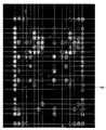
図3Aは、白血病を診断する際の診断ツールとして使用される試料スライド14の上部平面図である。結合パートナー102のアレイは、整列配置および強度補正目的のために一連のキャリブレーションドット104および106の列を含み、且つ、典型的に、最も明るいから最も暗いまでの、完全予想光学範囲をカバーする。結合パートナーを表すモノクローナル抗体等の基準結合パートナーから形成されたキャリブレーションドット108および110の外側周辺列が、最も暗い画像を産すると予想された。それとともに、外側周辺キャリブレーションドットは、画像構築を容易にするために、上記結合事象の空間的境界を規定する。一連のキャリブレーションドット104および106は、モノクローナル抗体から形成されてもよく、漸進的な稀釈によって所定の高濃度から低濃度へ変化する。診断マーカー112および114のアレイは、スライド上で中心に位置し、これは、治療マーカー116のサブアレイおよび診断およびQCマーカー118のサブアレイをさらに含む。アレイ112および114は実質的に同一であり、そのため、照合検査目的に使用することができ、結果は、より信頼のおける成果のために平均される。スライドに関するさらなる情報として、カタログ番号120、使用期限122、および、これおよびスライド上の他の情報をエンコードするバーコード124が挙げられる。
FIG. 3A is a top plan view of a
次に、図1へ戻ると、プルバー26は、画像形成装置10内の隔壁30を通って延在し、これは、光学装置10の内部を試料採取区域32と電気構成要素区域34とに分割する。例示的な実施形態において、隔壁30は、試料採取区域と電気構成要素区域との間に流体封止が形成されるように適合され、それによって、電気構成要素区域34内部の電気構成要素が試料採取区域32から汚染されることは妨げられる。
プルバー26は、封止部材36を経由して隔壁30を通って延在し、それは、プルバー26が動くのを可能にするように適合され、一方、試料採取区域32と電気構成要素区域34との間の流体封止を維持する。ドリップトレイ46には、分析中にスライド14から滴る可能性のある流体を集めるために、キャリッジ12が設けられてもよい。
Next, returning to FIG. 1, the
Pull
画像形成装置10は、スライド14に装着された結合した細胞状のまたはタンパク質のアレイ102(図3および3A)の画像を取るために、実質的に平坦な光のビーム38を発するためのLEDブラケット37をさらに具備する。ビーム38は、当初は、底部からスライドへ向けて方向づけられるように、第1の鏡(図示せず)によって反射される。スライドの上で、第2の鏡(図示せず)を使用して、結合した結合パートナー(図示せず)で回折しているかまたは他のやり方で屈折している光線を含む当初光ビームの一部40を、デジタルカメラ装置へ向けて方向づける。カメラは、上記カメラの画像キャプチャ能力に一致した速度で光源から発せられた光の束を通って動くときに、スライドまたは固相等価物で回折したかまたは他のやり方で屈折したずれた平坦な光の連続した線状画像を取る。屈折したビーム部分を方向づけるために鏡要素(図示せず)を適切に調節することによって、画像形成装置10は、結合したアレイの画像を導き出すために実質的に回折したかまたは他のやり方で屈折したビーム部分40のみがラインスキャンカメラ44に捉えられるように、適合することができることが、当業者によって認識される。
The
図4には、例示的な実施形態における光形態を例示する概略図が示される。LEDアレイ37から発したビーム38は、スライド14に入射する。スライド14に結合された結合パートナー(図示せず)で屈折した光線を含むビーム38の1つの部分40は、スライド14後に屈折した部分40として、屈折していない部分43に対して角度αで出現する。この角度αは、典型的に、3〜5度の範囲であり、経験的に、鏡の調節によって決定されてもよい。したがって、鏡45の適切な配向によって、実質的に回折した/屈折したかまたはずれた平坦な部分40のみがラインスキャンカメラ44へ向けて方向づけられ、屈折していない部分が、42に示されるように、カメラから離れて反射するのを保証することができる。スライド14に結合された結合パートナー(図示せず)で回折したかまたは屈折した光線を含む当初ビームの少なくとも1つの他の部分(図示せず)が、スライド14後に、屈折していない部分43に対して角度(−α)で出現すると予想されることが、当業者によって認識される。他方の回折した/屈折したかまたはずれた部分(単数または複数)が、異なる実施形態において、適切な反射配列を使用するかまたはカメラ44の視野の光学的変化によって、集合的に、交互に、または加えて、スキャンカメラ44へ向けて方向づけられてもよい。
FIG. 4 shows a schematic diagram illustrating the light configuration in an exemplary embodiment. A
試料スライド14に結合した結合パートナーの結果として回折しているかまたは他のやり方で屈折している光線のみを実質的に使用することによって、結合したアレイの陽画像を捉えることが可能になると出願人は認識している。言い換えると、試料スライド14の個別セクションの細胞または結合したパートナーの数は、捉えられた画像の光強度に比例し、それによって、暗視野画像を生じる。さらに、陽画像を捉えることは、照明ビームの伝達された部分の高い背景強度に関連した問題を回避することが認識される。図7は、例示的な画像60を示し、これは、下記により詳細に説明される。
Applicants will be able to capture a positive image of the combined array by using substantially only light rays that are diffracted or otherwise refracted as a result of the binding partner bound to the
次に、図5および5Aを参照すると、画像形成装置46の第2の好適な実施形態が示され、その中で、第1の実施形態のものに類似したかまたは同一である構成要素は、それに応じて参照符号が付されており、接尾に「a」が加えられている。キャリッジまたはスライドトレイ12aは、スライドに装着された結合アレイ102を分析するために、試料スライド14aを担持する。LEDの線状クラスタを担持するLEDブラケット37aを含むLED光源は、スライドの下側に向けて方向づけられる光の狭いビーム38aを発する。特定の実施形態において、490nmの青色発光波長を有する5つのLEDの線状クラスタを使用して、約10mmの幅を有するスライド上の帯を照明する。鏡45aは、アレイの結合した結合パートナーで回折しているかまたは他のやり方で屈折している光線を含む当初光ビームの部分40aを、ラインスキャン可能なデジタルカメラ装置44aへ向けて方向づける。実施形態において、バスラー(Basler)L101Kラインスキャンカメラが使用される。
Referring now to FIGS. 5 and 5A, a second preferred embodiment of the image forming apparatus 46 is shown, wherein components that are similar or identical to those of the first embodiment are: Correspondingly, a reference numeral is attached, and “a” is added to the suffix. The carriage or
一対の駆動トラック48を含むスライドトレイ12aは、DCモータ16aを使用して回転する一対の駆動ローラー18aおよびアイドラーローラー70によって、前後に動かされる。プッシュボタンを押して、試料スライドを挿入するためのスライドトレイ12aを呈する。試料スライドは、スライドトレイ12a内の窪み82内に挿入され、スライドの前縁は、ばね荷重されたスライドリテイナー83を押し上げ、スライドの後縁は、スライドストップ85に当接する。スライドセンサは、スライドによって変位されるときにカットアウト86の閉塞を検知することによって、スライドの存在を示す。ウインドウ87は、光ビーム38aがスライドの下側を照明するのを可能にし、フィンガ開口部88は、スライドを容易に取り外し交換するのを可能にする。
The
スライドセンサ89は、スライドが挿入されたときを検知し、コントローラ50aへ信号を送って、獲得を開始する。モータ16aは、それが光源37aから発した光の束38aを横切って動くスライド上の結合した細胞によって回折したかまたは他のやり方で屈折した光の連続した線状画像をラインスキャンカメラ44aが取るのに十分な速度で、スライドトレイ14aを前進させる。ラインスキャンカメラ44aは、1ピクセルの幅および1,024ピクセルの長さを有するセンサの線状アレイを有する。本実施形態において、これは、25mmの幅および0.025mmの長さを有する線状画像に等しい。結果として、スライドトレイが前方へ動くときには、結合した細胞アレイの連続した一連の線状画像が、ラインスキャンカメラ44aによって走査される。ラインスキャンカメラの線状開口部から離れて反射するときに、回折していないかまたは屈折していない光42がいかにして画像の形成で何の役割も演じないかは、図5から明らかである。スライドのバーコード124が画像形成領域に到達するときには、これは、マイクロスイッチ(図示せず)によって検知され、その結果として、光源37aがオフにされ、光源90がオンにされてスライドバーコードを照明し、それによって、バーコード124が画像に含まれることを可能にする。近位センサ81がスライドトレイの存在を検出し、プログラマブルロジックコントローラ(PLC)50aへ信号を送って、駆動モータを逆にし、試料スライド14aの除去を可能にする。蛍光色素による蛍光性の検出が必要な場合には、光源37aがオンにされる。スライドトレイの完全延長は、スライドトレイ上のセンサターゲット89を検知し、コントローラに信号を送って、駆動モータ16aをオフにする近位センサ80によって検出される。
The
図6Aにおいて、画像形成装置46の操作を制御するPLC50aは、プッシュボタン78と一緒に、入力として近位センサ80および81およびスライドセンサ89を有して示される。PLC出力は、DCモータ16a用のモータ前進および後進出力と、走査およびエラー事象をそれぞれ示すためのLED出力48aおよび49aを含む。それぞれ主要およびバーコード照明用の光源37aおよび90の操作を制御するための出力、および、フレームトリガ出力91も含まれる。
In FIG. 6A, the
本発明を体現する例示的な画像形成装置10および46の操作の基本的な原則は、図1、2、5および6を参照して、下記の通りである。
・展開したスライド14が、水平配向でスライドキャリッジ12および12A内に挿入される。
・スライド14は平坦な光ビーム38を通って運ばれ、一連の線状画像を得る。
・スライド14が首尾よく順次走査された場合には、LED48(図6)は走査が完了したことを示す。そうでない場合には、エラーインジケータ49および任意の可聴警報が作動する。診断チップが、機械または接続されたPCの液晶ディスプレイ(LCD)のディスプレイ51に表示される。追加インジケータは、走査LED49.1、完全ドリップトレイを示すための「トレイフル」LED49.2、および、画像形成装置がクリーニングを必要とする時を示す「クリーン」LED49.2を含む。
・スライド14は、機械から出て、取り外される。
・線状画像は処理ユニット50(図2)または外部のPC系フレームグラビングカードで処理され、結果はLCDディスプレイ51(図6)、シリアルポート52、および/または、イーサネット(登録商標)ポート54、または、PCモニタに利用可能にされる。
The basic principles of operation of exemplary
The unfolded
The
If the
•
The linear image is processed by the processing unit 50 (FIG. 2) or an external PC frame grabbing card, and the result is the LCD display 51 (FIG. 6),
例示的な実施形態において、結合された結合パートナーは、スライドを通って光を伝達することによって目に見えるようにされ、結合事象によってずれた平坦な配向で回折したかまたは他のやり方で屈折した光を見る。図7に示された画像60は、例示的な実施形態のプロトタイプを使用して取られた一連の線状画像から、順次組み立てられる。
画像60は比較的粗いが、結果を解釈するには十分な情報があることを当業者は認識する。本発明を体現する生産スキャナによって、よりはっきりした画像を捉えることができることが予想される。
In an exemplary embodiment, the bound binding partner is made visible by transmitting light through the slide and diffracted or otherwise refracted in a flat orientation displaced by the binding event. Watch the light. The
Those skilled in the art will recognize that the
例示的な実施形態のプロトタイプにおいて、細胞は、スライドを横切る狭い帯(およそ2mm)を通して見られる。スライドは、光源およびカメラに対して動かされ、各運動用に画像の薄い(0.025mm)スライスが取られ、次いで、処理ユニット50で再組み立てされ、これは、カメラの一部を形成してもよい。あるいは、カメラは、カメラリンクまたはデータコミュニケーションケーブルを経由してホストコンピュータのフレームグラビングカードと連通する。画像の獲得および処理は、コンピュータ系ソフトウェアに適切なものを使用して実行される。
In an exemplary embodiment prototype, cells are seen through a narrow band (approximately 2 mm) across the slide. The slide is moved relative to the light source and camera, and a thin (0.025 mm) slice of the image is taken for each motion and then reassembled in the
下記において、本発明の例示的な実施形態のいくつかのさらなる態様が検討される。
画像標準化および処理:
スキャナからスキャナへの画像、および、時間にわたる画像は、光源、画像形成装置、スライドの生態および他の環境条件の変化/劣化のために、同一患者試料で異なる。例えばモノクローナル抗体(Mab)62(図7)等の基準結合パートナーを、少なくとも、各アレイの4つの隅およびアレイの他の外側周辺に使用して、下記によって画像を標準化することができる。
・スライドの生態条件を示す;
・各ドットの強度用の上限を設定し、アレイのまわりの背景を測定することによって、強度範囲はゼロから最大細胞結合まで設定することができ、結果はそれにしたがってスケールされる。これは、システム(単/複)におけるいずれの変化/劣化を最小限にする;
・結合パートナー用の空間的境界を規定し、ひとたび見いだされると、上記結合パートナーのパターン認識用である。
In the following, some further aspects of exemplary embodiments of the present invention are discussed.
Image standardization and processing:
Scanner-to-scanner images, and images over time, are different for the same patient sample due to changes / degradation of light sources, imaging devices, slide biology and other environmental conditions. A reference binding partner such as monoclonal antibody (Mab) 62 (FIG. 7) can be used at least in the four corners of each array and the other outer periphery of the array to normalize the image by:
-Indicate the ecological conditions of the slide;
• By setting an upper limit for the intensity of each dot and measuring the background around the array, the intensity range can be set from zero to maximum cell binding and the results scaled accordingly. This minimizes any change / degradation in the system (s);
• Define spatial boundaries for binding partners and, once found, for pattern recognition of the binding partners.
Mab62は、ドットを各アレイに位置づけるのを助けることもできる。ひとたび各アレイの隅が識別されると、仮想グリッドが画像にオーバーレイされることができ、位置づけるか、または、他の非基準結合パートナーである。次いで、背景を取り除くことができ、当業者に公知の技術を使用して、画像が高められる。次いで、グリッドの各平方の平均強度を使用して、アレイの各ドットの細胞結合を定量化することができる。例えば0〜100または等価のピクセル強度から結果として得られたスケールの定量化は、容易に達成される。これを超える定量化レベルを達成しなければならないことが予想される。特定の処理要件に依存して、異なる実施形態では、より多くの基準結合パートナーまたは実際にはより少ない基準結合パートナーを使用することができることが、当業者によって認識される。そのような処理は、局所的にかまたはカメラから離れてかのいずれかで完了するか、または、画像キャプチャ直後かまたは未来の後の時間かのいずれかで完了することができる。
図8は、分子プロファイルを識別するのに使用されるパターン認識プログラムへつなぐためのアレイから得られてもよいデジタル情報を例示するマトリックスを示す。
下記のモデルは、本発明を体現するスキャナとそれが連通する他の装置との間の例示的な相互作用を概略する。
FIG. 8 shows a matrix illustrating digital information that may be obtained from an array for connection to a pattern recognition program used to identify molecular profiles.
The following model outlines an exemplary interaction between a scanner embodying the invention and other devices with which it communicates.
装置は、好ましくは、下記と連通することができる。
・外部または内部のコンピュータおよびプリンタ、例えば、病理学コンピュータおよびプリンタ、であり、既存のデータコミュニケーション標準およびプロトコルに従う必要があってもよい。
・基準データベース。
下記において、本発明を体現するスキャナの使用に先行し且つその後の他のプロセスの例が、例示的な実施のために簡単に概略される。
The device is preferably in communication with:
External or internal computers and printers, such as pathology computers and printers, which may need to follow existing data communication standards and protocols.
・ Reference database.
In the following, examples of other processes preceding and subsequent to the use of the scanner embodying the invention are briefly outlined for exemplary implementation.
スキャナに先行するプロセス:
一例として、スライドは、試料をスライドへ移すことによって展開され、それをインキュベートすることを可能にし、次いで、スライドを燐バッファ生理食塩水(PBS)で2回洗浄し、細胞内タンパク質コンパートメントへアクセスするために化学薬品を備えていても備えていなくてもよく、且つ、蛍光的に活性な分子、例えば、蛍光色素マーカー(図8に関連して下記に説明される異なる例示的な試料タイプを参照する)を備えていても備えていなくてもよく、ホルムアルデヒドに固定し、次いで、PBSで2回またはそれ以上洗浄する。
The process preceding the scanner:
As an example, the slide is developed by transferring the sample to the slide, allowing it to be incubated, then the slide is washed twice with phosphate buffered saline (PBS) to access the intracellular protein compartment. For example, with or without chemicals, and with fluorescently active molecules, such as fluorescent dye markers (see different exemplary sample types described below in connection with FIG. 8). With or without), fixed in formaldehyde and then washed twice or more with PBS.
スキャナの後のプロセス:
スライドは、生物的廃棄物に廃棄される。
スキャナは、好ましくは、下記を可能にする適切な材料および特徴を備えて設計される:
・中性洗剤による外部クリーニング
・スライドを汚染させない(生物的および他)
・スライドレセプタクルがクリーニングされ、殺菌され、スライドからこぼれる可能性のあるいずれの流体を排出させることを可能にする
・標準ガラスフォーマットまたは等価物を受け入れ、500,000操作サイクルを超えて維持する。
Process after the scanner:
Slides are discarded into biological waste.
The scanner is preferably designed with appropriate materials and features that allow:
・ External cleaning with neutral detergent ・ Do not contaminate slides (biological and others)
• Allow the slide receptacle to be cleaned, sterilized, and drain any fluid that may spill from the slide. • Accept standard glass format or equivalent and maintain over 500,000 operating cycles.
図9は、二重検出様相の操作のために、本発明を体現する画像形成装置における光学形態を例示する概略図である。この実施形態において、実質的に平らなビーム116がLED光源110から発せられ、試料スライド114の下側へ向けて可変波長を発することができる。図4に関連して上記に説明されたように、光ビーム116の狭い部分がスライド114を通って伝達され、試料スライド114の頂部から伝達された部分118として出現する。
FIG. 9 is a schematic view illustrating an optical configuration in an image forming apparatus embodying the present invention for the operation of the double detection mode. In this embodiment, a substantially
図9に記載された構成において、試料スライド114は、蛍光マーカーを使用して、結合パートナーの試料中に、特定の分子例えばタンパク質の存在を識別する試料を含む。この実施形態には狭いビーム光源110が選ばれ、そのスペクトル内に、蛍光マーカーを励起するのに適切な波長を含み、結果として、蛍光マーカーから光が発せられる。図9に例示されるように、蛍光マーカーから発した光は、点源から発するとみなされてもよく、したがって、全方向性発光場120を産し、その後の再構築のために一連の線状画像を形成する。
In the configuration described in FIG. 9, the
したがって、鏡要素122として、全方向性蛍光発光の一部は、矢印124で示されるように、バスラーL301KL等のモノクロおよび多色検出126ができるラインスキャンカメラの形態のデジタルカメラ装置へ向けて、方向づけられる。鏡122の角位置を適切に選択することによって、照明する光ビーム116の伝達された部分118が、126で示されるようにラインスキャンカメラから離れた鏡要素122で反射することを確実にし、すなわち、「補正」角度は、伝達されたビーム部分118に対してずれている。
Therefore, as a
光回折/屈折および蛍光検出は、両方とも、線状画像の再構築を必要とし、同時にまたは各画像で交互に、ラインスキャンカメラへ向けて方向づけられる。二重検出様相は、平らな光源から照明する光の波長が、単数または複数の蛍光的に活性な分子の励起波長に近いときに、最良に使用される。さらに別の実施形態において、異なる蛍光的に活性な分子のマルチプレックスは、カメラの多色検出能力に依存して、交互操作モードまたは同時操作モードのいずれかで、平坦なおよび/またはずれた平坦な画像をカメラシステムへ方向づけた後に発生する。 Both light diffraction / refraction and fluorescence detection require reconstruction of a linear image and are directed towards a line scan camera, either simultaneously or alternately in each image. Dual detection modalities are best used when the wavelength of light illuminating from a flat light source is close to the excitation wavelength of one or more fluorescently active molecules. In yet another embodiment, the multiplex of different fluorescently active molecules is flat and / or off-flat in either alternating mode or simultaneous mode depending on the multicolor detection capabilities of the camera. Occurs after directing the correct image to the camera system.
本発明の1つの実施形態において、ラインスキャンカラーカメラは、スライドが前方へ通過する間に、回折したかまたは他のやり方で屈折した光を検出し、装置から出るときに、スライドの後方へ通過する間に、光の蛍光放出を検出するように配列される。したがって、カメラは、前方通過ではモノクロ検出モードで操作し、後方通過中に多色検出モードに転換する。戻り通過において、スライドは、より遅い速度で移動し、より長い露出時間の間に、蛍光色素から発したより弱い信号を検出することを可能にする。適切な帯域通過フィルタセット、例えば、オメガオプティカル社(Omega Optical, Inc.)が供給したオメガ(Omega)フィルタ、および、クロマテクノロジー社(Chroma Technology Corp.)が供給したクロマ(Chroma)フィルタを使用して、選択された染料/核酸複合体に対して励起および放出のピークを刺激するために補正波長を使用することを確実にしてもよい。しかし、好ましくは、フィルタを使用する必要なく検出可能な励起が達成されるように光の波長が選択され、ソフトウェア規制識別を使用する。本ケースでは、セルトラッカー(celltracker)緑色蛍光色素に適切であるとして、青色LED配列が選ばれる。二色または三色のLEDを使用して、多くの蛍光色素を励起することができる波長のより広い範囲を提供してもよいことが認識される。各結合事象を制定する画像再構築は、各検出モードから導き出された1つまたはそれ以上のデジタル画像に基づいている。 In one embodiment of the present invention, the line scan color camera detects light that is diffracted or otherwise refracted while the slide passes forward and passes back to the slide as it exits the device. In the meantime, it is arranged to detect the fluorescence emission of light. Therefore, the camera operates in the monochrome detection mode for forward passage and switches to the multicolor detection mode for backward passage. In the return pass, the slide moves at a slower speed, allowing a weaker signal emitted from the fluorescent dye to be detected during the longer exposure time. Appropriate bandpass filter sets are used, such as the Omega filter supplied by Omega Optical, Inc. and the Chroma filter supplied by Chroma Technology Corp. Thus, it may be ensured that the correction wavelength is used to stimulate excitation and emission peaks for the selected dye / nucleic acid complex. Preferably, however, the wavelength of light is selected such that detectable excitation is achieved without the need to use a filter, and software regulatory identification is used. In this case, a blue LED array is chosen as appropriate for the cell tracker green fluorescent dye. It will be appreciated that bi- or tri-color LEDs may be used to provide a wider range of wavelengths that can excite many fluorescent dyes. The image reconstruction that establishes each binding event is based on one or more digital images derived from each detection mode.
次に、先に図7および8に関して参照した画像標準化および処理手順が、図10のフローチャートおよび添付の図面を参照してより詳細に説明される。画像形成装置10または46は、先に説明したやり方で、130に示されるように、デジタルデータを生成する。カメラまたは外部マイクロプロセッサの一部を形成するフレームグラバーカードの画像グラバーソフトウェアは、132に示されるように、連続した線状セクションから複合生画像(図8)を構築する。画像処理ソフトウェアは、134に示されるように、各結合事象用に画像強度を生成するように生複合画像をインポートする。
Next, the image standardization and processing procedure referred to above with respect to FIGS. 7 and 8 will be described in more detail with reference to the flowchart of FIG. 10 and the accompanying drawings. The
画像処理方法は、複合画像を滑らかにしてピクセル強度136の高周波数変動を除去することと、次いで、ステップ138に示されるように、全強度の輪郭マップの形態で一連の同心性の線を生成し表示する前に、輝度の対数目盛でグレーの8つのレベルに画像を転換することと、を含む。滑らかにすることによって、輪郭線をギザギザにしギャップを残す可能性がある高周波数情報を画像から除去する。画像は、輝度の対数目盛でグレーの8つのレベルに画像を転換され、これは、全画像輝度レベルを下記の値、すなわち、1、2、4、6、8、16、32、64および128へ転換するように設定された256ビットルックアップテーブルを使用して形成される。画像ピクセル輝度値は、このアレイを調べるインデックスとして使用される。異なるグレーレベルの間の境界を使用して、輪郭線を形成する。
The image processing method smooths the composite image to remove high frequency variations in
輪郭マップは、最大強度ピクセル、すなわち、255の値を有する白ピクセルの背景から構成される。プロセスは、xおよびyループ内部の各ピクセル要素にアクセスすることによって、画像を検討する。その要素は、8つの取り巻くピクセルの中心として処理される。プログラムが、それよりも明るい8つのピクセルを備えた中心ピクセルを見出した場合には、中心ピクセルは輪郭上にあるとしてマークする。マーキングは、ピクセル値(値1、2、4、6、8、16、32、64、128の1つのみを保持する)を第2のアレイへコピーして、画像の輪郭線のピクセルのみを保持することによって行われる。結果は、画像と同一の寸法のアレイであり、すべてのピクセルは255に設定されるが、隣よりも暗い領域の外側縁のグレー値を保持する輪郭線にあるピクセルを除く。図7の画像から導き出された典型的な輪郭マップは、図10Aの140に示される。
The contour map consists of a background of maximum intensity pixels, ie white pixels having a value of 255. The process considers the image by accessing each pixel element inside the x and y loops. That element is treated as the center of the eight surrounding pixels. If the program finds a center pixel with 8 pixels brighter than it, it marks the center pixel as being on the contour. The marking copies the pixel values (holding only one of the
輪郭線内のすべての画像物体の位置づけおよび識別が発生し、ステップ139に示されるように、真円度に対する確認および向上が提供される。続く標準化ステップ142において、輪郭線に関連した画像向上が発生して、過剰な暗さを除去し、それによって、空間変化およびアレイを横切る強度に対処するために、真円度をさらに改良し、画像を標準化する。次に、特に、上記プロセスから生じる各別個の輪郭線が、空間画像物体として分類される。各輪郭線が分類されるときに、そのピクセルは、画像と同一の寸法を備えた「既に処理された」アレイに加えられる。これによって、その線のいずれのピクセルを調べることによって、所与の輪郭線が既に処理されているか否かに関する即座の情報が可能になる。ピクセルの座標を使用して、先にクリアされた「既に処理された」アレイの対応する要素にアクセスする。
Positioning and identification of all image objects within the contour occurs, providing confirmation and improvement to roundness, as shown in
輪郭マップアレイの各ピクセルは、ループ用にxおよびyによって走査される。ピクセルが、新しい(未処理の)輪郭の一員であるとわかった場合には、その座標は、イメージオブジェクトピクセルファインド(ImageObjectPixelFind)方法へ移動し、これは、輪郭線の残りのピクセルを見出し、輪郭を開または閉として分類する。 Each pixel of the contour map array is scanned by x and y for a loop. If the pixel is found to be part of a new (unprocessed) contour, its coordinates are moved to the ImageObjectPixelFind method, which finds the remaining pixels of the contour, Is classified as open or closed.
方法は、輪郭線のすべてのピクセルを見出し、各々に、「既に処理された」アレイの「既に処理された」としてフラグをつける。これは、輪郭線の各ピクセルの対応するXおよびY座標を保持する2つの他のアレイ、領域X()および領域Y()を戻す。これらの2つのアレイは本質的に、輪郭線のすべてのピクセルを挙げる。これらの2つのアレイに含まれるピクセル座標は、次いで、画像物体(すなわち、輪郭線)のアレイにコピーされ、これは、各画像物体のすべてのピクセル、さらに、物体内のピクセルの数、および、その物体(すなわち、その対数グレースケール輝度のグレースケール領域を含む輪郭線)のグレースケール輝度のリストを保持する。 The method finds all pixels of the contour and flags each as “already processed” in the “already processed” array. This returns two other arrays, region X () and region Y (), that hold the corresponding X and Y coordinates of each pixel of the contour line. These two arrays essentially list all the pixels of the outline. The pixel coordinates contained in these two arrays are then copied to an array of image objects (i.e. contour lines), which includes all the pixels of each image object, plus the number of pixels in the object, and A list of gray scale luminances of the object (ie, the contour line containing the gray scale region of the log gray scale luminance) is maintained.
結果は、各画像物体(輪郭線によって表される)が識別され、イメージオブジェクト()アレイにリストされ、その物体用のピクセルのリストの各ピクセルを処理することによって即座に検討することができる。45ピクセルを超える輪郭を備えた円形物体の数が10未満である場合には、画像は次のメッセージで拒絶される:
「この画像は不良すぎて処理できない。(十分な認識可能なドットがない)。おそらく、スライドが乾燥していたのではないか。再湿潤して、再度走査するかまたは再処理してください。」
The results can be examined immediately by identifying each image object (represented by the outline) and listing it in the image object () array and processing each pixel in the list of pixels for that object. If the number of circular objects with contours greater than 45 pixels is less than 10, the image is rejected with the following message:
“This image is too bad to be processed (not enough recognizable dots). Perhaps the slide was dry. Rewet and rescan or reprocess. "
次いで、画像物体は、円形であるか否かが分類される。分類は、単一の画像物体を分析する方法によって実行される。このルーチンは、画像で各物体を処理するループに入れられる。ルーチンを使用して、物体の輪郭線の長さ、および、閉鎖物体であるか開放物体であるかを計算する。閉鎖は、輪郭がループであることを意味する。開放は、端部分が一致していない線であることを意味する。各物体は、連続した輪郭線を有する。ルーチンはまた、イメージオブジェクトセンター(ImageObjectCenter)を使用していずれの閉鎖物体の中心の位置を見出し、XおよびY方向における直径も見出す。次いで、物体の円周およびその直径情報を使用して、ルーチンは物体が円形であるか否かを分類する。 The image object is then classified as to whether it is circular. The classification is performed by a method that analyzes a single image object. This routine is entered into a loop that processes each object with an image. The routine is used to calculate the length of the object outline and whether it is a closed or open object. Closure means that the contour is a loop. Open means that the end portion is a line that does not match. Each object has a continuous outline. The routine also uses the Image Object Center (ImageObjectCenter) to find the position of the center of any closed object and find the diameter in the X and Y directions. Then, using the object's circumference and its diameter information, the routine classifies whether the object is circular.
結果は、一定の画像物体が今や円形として分類されるということである。これらは、アレイのドットの輪郭用の候補である。多くのこれらの物体の中心は、アレイのドットの中心に一致する。これらの物体およびその中心を位置づけるプロセスは、アレイを画像のいずれかに位置づける作業の背部を破り、仮想グリッドがその上に正確に整列配置されるのを可能にする。 The result is that certain image objects are now classified as circular. These are candidates for the outline of the dots in the array. The center of many of these objects coincides with the center of the array dot. The process of positioning these objects and their centers breaks the back of the task of positioning the array on any of the images and allows the virtual grid to be accurately aligned on it.
画像向上ルーチンは、画像を高めて、重要な情報を含む輝度の範囲のみを示す。これは、ほとんど情報を有さない非常に暗い区域を除去することによって、画像の情報部分のコントラストを高める。これは、ドットを示す円形領域を検出するのをより容易にし、診断的正確度を高めるために、画像を幾分標準化する傾向もある。 The image enhancement routine enhances the image to show only a range of brightness that includes important information. This increases the contrast of the information part of the image by removing very dark areas with little information. This also tends to standardize the image somewhat in order to make it easier to detect circular areas showing dots and to increase diagnostic accuracy.
いずれの輝度レベルが情報を含むかを発見する1つの方法は、いずれの円形領域(最も暗いレベルで開始する)を含む第1の対数輝度レベルを求めることである。輪郭輝度は、8ステップで1から128へ走行し、毎回、輝度が倍加する。少なくとも1つの適切な円形物体を含む第1のレベルは、レベルnとラベルづけられる。次いで、画像は再処理され、レベルn−1(Bn-1)の輝度Bと255との間の情報のみを示す。これは、下記の公式を画像の各ピクセルへ加えることによって行われ、新しく高められたコントラスト画像のピクセルを生成する。
画像のすべてのピクセル座標x、y用に、
PixelValue(x、y)new=Max(0,(255*PixelValue(x、y)old−Bn-1)/(255−Bn-1))))
であり、ただし、Max()関数は、単に、負の輝度値を有する新しいピクセルがないことを確実にするだけである。
One way to find out which luminance level contains information is to determine a first log luminance level that includes which circular area (starting with the darkest level). The contour brightness runs from 1 to 128 in 8 steps, and the brightness is doubled every time. The first level containing at least one suitable circular object is labeled level n. The image is then reprocessed to show only information between luminance B and 255 at level n-1 ( Bn-1 ). This is done by adding the following formula to each pixel of the image to produce a new enhanced contrast image pixel.
For all pixel coordinates x, y in the image,
PixelValue (x, y) new = Max (0, (255 * PixelValue (x, y) old - Bn-1 ) / (255- Bn-1 ))))
However, the Max () function only ensures that there are no new pixels with negative luminance values.
次いで、新しく高められた画像は、第2フェーズで完全に再処理され、新しいセットの輪郭物体を獲得する。これは、8レベル輝度領域および輪郭物体を完全に再生成し、それらを再分類することを含む。しかし、この向上プロセスは、処理の第2フェーズから明らかに省略される。このステップは146で示され、図10Bに示されるように、画像上に仮想グリッド147を当初配置する。
The newly enhanced image is then completely reprocessed in the second phase to obtain a new set of contour objects. This involves completely regenerating the 8-level luminance region and the contour object and reclassifying them. However, this enhancement process is clearly omitted from the second phase of processing. This step is indicated at 146 and initially places a
アレイのカラムを見出すために、単一のヒストグラムが、円形物体の数の画像にわたって引かれ、x座標は各ヒストグラムセル内に入る。ヒストグラムセルは、1ピクセル幅である。ヒストグラムは、画像の幅にわたって続く。カラムを見出すときには、円形物体のy座標は無視される(類似プロセスを使用して列を見出すが、この場合は、ヒストグラムはアレイ下に引かれ、xおよびy座標の使用は逆にされる)。ドットがカラムに入る場合には、ヒストグラムは各カラムのピークを示す。
単に画像のドットが少なすぎてこれを可能にすることができないのでなければ、ピークを見て最良の一体化カラム分離を見出すことによって、グリッド上の各カラムの場所を識別することができる。ヒストグラムは、そのピークを確実に検出するために、滑らかさを必要とする。
To find the columns of the array, a single histogram is drawn over the image of the number of circular objects and the x coordinate falls within each histogram cell. The histogram cell is 1 pixel wide. The histogram continues over the width of the image. When finding the column, the y coordinate of the circular object is ignored (a similar process is used to find the row, but in this case the histogram is drawn under the array and the use of x and y coordinates is reversed). . If a dot enters a column, the histogram shows the peak for each column.
Unless the image has too few dots to allow this, the location of each column on the grid can be identified by looking at the peak to find the best integrated column separation. The histogram needs smoothness to reliably detect its peak.
ヒストグラムのピークが不鮮明である場合には、または、近い間隔の二重ピーク有する場合には、スライド画像はおそらくねじれている。アルゴリズム評価、テストおよびデバッグを補助するために、画像のオーバーレイとしてヒストグラムを引くのを補助してもよい。結果として、アレイの少なくともいくつかの列およびカラムの位置は公知であり、カラム分離および列分離を制定することができ、長さ転換スケールがアレイ設計とアレイ画像との間に展開されるのを可能にする。 If the histogram peaks are smeared, or if they have closely spaced double peaks, the slide image is probably twisted. To assist in algorithm evaluation, testing and debugging, it may be helpful to draw a histogram as an overlay of the image. As a result, the position of at least some rows and columns of the array is known, column separation and row separation can be established, and the length conversion scale can be developed between the array design and the array image. enable.
各画像物体は、可能であれば、識別されたグリッド列の1つに割り当てられる。円形とフラグづけられ有効カラムにあるいずれの画像物体は、見出された列の1つに割り当てられ、それが特定の限定内に入ることを提供する。
様々な要因のため、列のねじれがカラムのねじれと同一であると仮定することは安全ではないことがわかり、言い換えると、ねじれはすべてが画像回転によるものではなく、画像歪曲の他の形態によるものもある。したがって、垂直および水平のねじれは、別個に取り除かれる。しかし、ねじれは線状であると仮定され、いずれの高次歪曲は補正されない。
Each image object is assigned to one of the identified grid columns if possible. Any image object that is flagged as circular and in the active column is assigned to one of the found rows, providing that it falls within certain limits.
It turns out that it is not safe to assume that the row twist is the same as the column twist due to various factors, in other words, the twist is not all due to image rotation, but due to other forms of image distortion There are also things. Thus, vertical and horizontal twists are removed separately. However, the twist is assumed to be linear and no higher order distortion is corrected.
見出された各グリッドカラムでは、そのカラムの傾斜は、そのカラムに入るとフラグづけられた画像物体のx、y座標へ、直線を適合させることによって識別される。この適合は、標準最小二乗法を使用して実行される。すべてのカラムの傾斜を平均して、画像用の平均垂直ねじれを見出す。ねじれ補正ステップは、フローチャートの150に例示される。列のねじれが見出され、類似の方法で補正される。 For each grid column found, the slope of that column is identified by fitting a straight line to the x, y coordinates of the image object flagged as entering the column. This fitting is performed using the standard least squares method. Average the slope of all columns to find the average vertical twist for the image. The twist correction step is illustrated at 150 in the flowchart. Row twist is found and corrected in a similar manner.
ひとたび画像がねじれ補正されると、高められたねじれ補正画像でもう1度、画像分析が繰り返され、画像区域および輪郭線を再形成し、画像物体を再分類する。明らかに、この第3フェーズでは、向上およびねじれ補正プロセスは省略される。
合理的な境界内のカラム列交差に入るこれらの円形画像物体は、ドットとして分類される。他の画像物体はドットとして分類されず、下記のプロセスで無視される。
Once the image has been twist corrected, the image analysis is repeated once more with the enhanced twist corrected image to recreate the image areas and contours and reclassify the image objects. Obviously, in this third phase, the enhancement and twist correction process is omitted.
Those circular image objects that fall into column row intersections within reasonable boundaries are classified as dots. Other image objects are not classified as dots and are ignored in the following process.
先に生成された列およびカラムの分離を使用して、概算のXおよびYスケール(まったく異なっていてもよい)を生成する。次いで、これらのスケールを使用して、画像ピクセルをmmに転換することができ逆も可能であり、そのため、スライド定義の寸法を画像のアレイ部分の寸法に関係づけることができ、フローチャートのステップ152に示される。
スライドの最初および最後のカラムを使用して、アレイを保持する画像のその部分によって対するアレイ定義を位置づける。X座標はアレイの最初および最後のカラムから公知であり、それから、残りの内部カラムの座標を算定することができる。
The previously generated row and column separations are used to generate approximate X and Y scales (which may be quite different). These scales can then be used to convert image pixels to mm and vice versa, so that the dimensions of the slide definition can be related to the dimensions of the array portion of the image, step 152 of the flowchart. Shown in
The first and last columns of the slide are used to position the array definition relative to that portion of the image holding the array. The X coordinate is known from the first and last column of the array, from which the coordinates of the remaining internal columns can be calculated.
図10Bに示されるように、仮想グリッドを備えた画像のオーバーレイが表示される。座標の中心は、最も近い画像データを見出すことによって各平面隅ドットへ位置づける。高められたねじれ補正画像は、円で囲まれた推論された隅ドットでオペレータへオーバーレイされる。次いで、オペレータは、不良品質画像のために隅ドットを位置づけられなかった場合に、隅ドットを位置づけるという選択肢を有する。ひとたびオペレータが最終ドットをクリックすると、位置を使用して、アレイの画像に対するスライド平面を可能にする。 As shown in FIG. 10B, an image overlay with a virtual grid is displayed. The center of coordinates is located at each planar corner dot by finding the closest image data. The enhanced twist correction image is overlaid to the operator with inferred corner dots surrounded by a circle. The operator then has the option of positioning the corner dot if the corner dot is not positioned due to a bad quality image. Once the operator clicks on the last dot, the position is used to allow a sliding plane for the image of the array.
新しい隅ドット位置を使用して、画像ピクセルとmmとの間のより正確な転換スケールを計算することが可能である。これによって、スライドのアレイ区域の平面を表す仮想グリッドがアレイの画像に対して正確に位置づけることを可能にし、そのため、各ドットはその自己のグリッド方形の中心にあるように見える。
ピクセルからmmへ転換する新しいxおよびyスケールは、適切な方向のピクセルにおける4つの隅ドットの中心のx−y座標の距離を、スライド定義(Slide Definition)から導き出されたアレイ平面上のこれらのドットのmm距離に対して比較することによって、計算される。
Using the new corner dot positions, it is possible to calculate a more accurate conversion scale between image pixels and mm. This allows a virtual grid representing the plane of the array area of the slide to be accurately positioned with respect to the image of the array so that each dot appears to be in the center of its own grid square.
The new x and y scales that convert from pixel to mm are the distances in the xy coordinates of the center of the four corner dots in the pixel in the appropriate direction, and those on the array plane derived from the Slide Definition. Calculated by comparing against the mm distance of the dots.
列の場合はより厳しいが、それは、アレイの頂部および底部の列が、左および右のカラムよりも独特ではないからであり、画像上にすべてをはっきり示さない漸次稀釈される抗体サブタイプを保持する。さらに、完全な頂部および底部の列は、流体、流体縁および波からの偽光、および/または、頂部または底部で開始するスライドからの漸次乾燥によって、ほとんど曖昧であることもあり、目に見えるドットをほとんど有さない列もあるため、すべての列が、初期のプロセスで識別されているわけではない。 More stringent for rows, because the top and bottom rows of the array are less unique than the left and right columns, and retain progressively diluted antibody subtypes that do not show all clearly on the image To do. In addition, the complete top and bottom row may be almost ambiguous and visible due to fluids, spurious light from fluid edges and waves, and / or gradual drying from slides starting at the top or bottom. Not all columns have been identified in the initial process because some columns have few dots.
したがって、異なるアルゴリズムを使用して、スライド平面を垂直方向の画像に対して整列配置させる。第1に、上記から派生した概算スケールを使用して、列分離をmmに転換する。次いで、スライド設計は、概念的には、画像上を垂直に上下に摺動し、(a)左および右の縁ドットとして認識される円形画像物体と、(b)平面の縁ドットとの間の最良適合を求める。これは、平面をスライド画像下に一時に1ピクセルずつ概念的に動かし、各画像ドットと平面上のその最も近い隣との間の総距離を合計することによって、単一の通過で反復して行われる。最短のそのような距離およびそのピクセルインデックスは、反復中に記録される。反復が完了したときには、この特定の場所は、アレイの画像に対してスライド設計を整列配置するための最良の推測である。
ドット読取エラーが検出される場合には、入力されたデータはスクリーンに残り、オペレータは、180に示されるように、画像を再走査するという選択肢を有する。
Therefore, a different algorithm is used to align the slide plane with the vertical image. First, convert the column separation to mm using an approximate scale derived from the above. The slide design then conceptually slides up and down vertically on the image, between (a) a circular image object that is recognized as the left and right edge dots, and (b) between the edge dots on the plane. Find the best fit. This is repeated in a single pass by conceptually moving the plane one pixel at a time below the slide image and summing the total distance between each image dot and its nearest neighbor on the plane. Done. The shortest such distance and its pixel index are recorded during the iteration. When the iteration is complete, this particular location is the best guess for aligning the slide design with the images of the array.
If a dot reading error is detected, the entered data remains on the screen and the operator has the option to rescan the image as indicated at 180.
ステップ158で、識別されたように各ドットの平均補正強度を使用して計算された背景補正が実行される。強度値は、1つずつ読み取られる。図10Cに示されるように、ドットを含むグリッド平方ロケータにおける各ピクセルの0から255の画像強度から、ヒストグラム162が形成される。局所背景強度が見出され、ピクセル輝度レベルMとして規定される。Mは領域内のピクセルを2つのセットに分割し、すなわち、より暗いセットは、輝度がMより暗いか等しいすべてのピクセルを含み、より明るいセットBは、Mよりも明るいセットのすべてのピクセルを含む。セットAのピクセルの数は、セットBのピクセルの数に対して予め設定された割合を有し、典型的に50%である。
At
いずれのピクセルが局所背景(上記)の一部であるかを決定した後に、今や、各ドットの相対輝度を計算することは容易である。
プロセスは、計算された半径に基づいて、ドット領域内部のすべてのピクセルの画像強度を合計することによって開始する。アルゴリズムもまた、部分的にドット半径内部にあるピクセルの考慮を含み、ドット内部にあるピクセルの画分にしたがってわずかな部分のプロラタを蓄積する。合計された数(デルタ)は、ピクセル輝度から、上記に計算された局所背景輝度を引いたものをである。
After determining which pixels are part of the local background (above), it is now easy to calculate the relative brightness of each dot.
The process begins by summing the image intensities of all pixels within the dot area based on the calculated radius. The algorithm also includes consideration of pixels that are partially inside the dot radius and accumulates a small portion of the prorata according to the fraction of pixels that are inside the dot. The total number (delta) is the pixel luminance minus the local background luminance calculated above.
次いで、ピクセル当たりのこの合計の平均値(内平均値(InnerAverageValue))は、画分部分を含むドット内部のピクセルの合計数で、合計を割ることによって、計算される。
次いで、ドット値(Dot Value)は、内平均値を取り、これを標準化して、局所背景上の最大可能輝度に対する割合として表すことによって、形成される。
The average value of this sum per pixel (inner average value) is then calculated by dividing the sum by the total number of pixels inside the dot including the fractional part.
The dot value is then formed by taking the inner average value and normalizing it and expressing it as a percentage of the maximum possible luminance on the local background.
ステップ164に示されるように、ひとたびドット値が識別され、図8に例示されるようにマトリックスに組み込まれると、ソフトウェアは、未知のドットパターンまたは分子プロファイルを、疾病シグネチャのライブラリから公知のコンセンサスパターンへ最良適合するために、反復アプローチを実行する。分子プロファイルを表すグラフ化および表化は、166で提供され、診断の基礎としてまたは序列法に基づいた予後決定の基礎として、コンセンサスパターンのライブラリに対して、最良に適合した分子プロファイルが確認される。不満足の場合には、分析が168で繰り返されてもよく、または、画像が180で再走査されてもよい。ひとたび適合した分子プロファイルが得られると、170に示されるように、診断レポートが印刷され、データは中央データベースに送られる。
As shown in
広く説明されたように本発明の精神または範囲から逸脱せずに、特定の実施形態に示されたような本発明に対して、多数の修正および/または変形が行われてもよいことが、当業者によって認識される。従って、本実施形態は、あらゆる点において例示的なものであり、限定的なものではないことを考慮すべきである。
例えば、一定の例示的な試料材料が説明されているが、本発明は、特定の試料材料の分析に限定されないことが認識される。さらに、本発明は、診断または予後の適用に使用されることに限定されないことが認識される。
It will be appreciated that numerous modifications and / or variations may be made to the invention as set forth in the specific embodiments without departing from the spirit or scope of the invention as broadly described. Recognized by those skilled in the art. Therefore, it should be considered that this embodiment is illustrative in all respects and not restrictive.
For example, while certain exemplary sample materials have been described, it will be appreciated that the present invention is not limited to the analysis of specific sample materials. Furthermore, it will be appreciated that the present invention is not limited to use in diagnostic or prognostic applications.
下記の特許請求の範囲においておよび本発明の開示において、言語または必要な含意を表現するために文脈によって別なものが必要とされる場合を除いて、「具備する」という単語は、「含む」という意味で使用され、すなわち、特定された特徴は、本発明の様々な実施形態のさらなる特徴に関連してもよい。 In the claims below and in the present disclosure, the word “comprises” includes “unless” unless otherwise required by context to express language or the necessary implications. In other words, the identified features may relate to further features of various embodiments of the invention.
Claims (13)
−前記試料スライドを照明するための光源と、前記試料スライドは試料のアレイを含み、
−前記試料スライドの連続した部分が前記光源によって照明されるように、前記キャリアステージ及びそれに担持された前記試料スライドを動かすための駆動手段と、
−少なくとも2つのモード、すなわち、回折または偏向モードと、蛍光モードとで作動するように構成され、
前記駆動手段が前記キャリアステージを第1の方向に動かすときには前記回折または偏向モードで作動するように構成され、また、前記駆動手段が前記キャリアステージを第2の方向に動かすときには前記蛍光モードで作動するように構成され、
前記回折または偏向モードでは、前記試料スライド上の試料のアレイで回折または偏向された光線がカメラによって捉えられ、また、前記蛍光モードでは、試料のアレイ上の蛍光マーカーから発せられた光線が捉えられ、
使用の際に、前記試料スライドを通って伝達される前記光源からの光線に対してあるずれた角度で前記試料スライドから出る光線の連続する部分のみを実質的に捉えて、前記試料スライドまたは試料のアレイの画像へと再構築されるように構成された一連の部分的な画像を生成するように配置されたデジタル光学カメラシステムと、
を具備する画像形成装置。A carrier stage for carrying the sample slide;
A light source for illuminating the sample slide, the sample slide including an array of samples;
Driving means for moving the carrier stage and the sample slide carried thereon so that a continuous part of the sample slide is illuminated by the light source;
-Configured to operate in at least two modes: diffraction or deflection mode and fluorescence mode;
The driving means is configured to operate in the diffraction or deflection mode when moving the carrier stage in a first direction, and operates in the fluorescence mode when the driving means moves the carrier stage in a second direction. Configured to
In the diffraction or deflection mode, a light beam diffracted or deflected by the sample array on the sample slide is captured by the camera, and in the fluorescence mode, a light beam emitted from a fluorescent marker on the sample array is captured. ,
In use, the sample slide or sample is substantially captured only in a continuous portion of the light beam exiting the sample slide at an offset angle with respect to the light beam from the light source transmitted through the sample slide. A digital optical camera system arranged to generate a series of partial images configured to be reconstructed into images of an array of
An image forming apparatus comprising:
Applications Claiming Priority (2)
| Application Number | Priority Date | Filing Date | Title |
|---|---|---|---|
| AU2003900924A AU2003900924A0 (en) | 2003-02-28 | 2003-02-28 | Imaging device |
| PCT/AU2004/000264 WO2004077031A1 (en) | 2003-02-28 | 2004-03-01 | Imaging device |
Publications (3)
| Publication Number | Publication Date |
|---|---|
| JP2006519365A JP2006519365A (en) | 2006-08-24 |
| JP2006519365A5 JP2006519365A5 (en) | 2007-02-15 |
| JP4633712B2 true JP4633712B2 (en) | 2011-02-16 |
Family
ID=31499970
Family Applications (1)
| Application Number | Title | Priority Date | Filing Date |
|---|---|---|---|
| JP2006501387A Expired - Fee Related JP4633712B2 (en) | 2003-02-28 | 2004-03-01 | Image forming apparatus |
Country Status (11)
| Country | Link |
|---|---|
| US (1) | US7680316B2 (en) |
| EP (1) | EP1604188A4 (en) |
| JP (1) | JP4633712B2 (en) |
| KR (1) | KR101071439B1 (en) |
| CN (1) | CN100557417C (en) |
| AU (1) | AU2003900924A0 (en) |
| BR (1) | BRPI0406959A (en) |
| CA (1) | CA2508846C (en) |
| NZ (1) | NZ540405A (en) |
| WO (1) | WO2004077031A1 (en) |
| ZA (1) | ZA200507598B (en) |
Families Citing this family (21)
| Publication number | Priority date | Publication date | Assignee | Title |
|---|---|---|---|---|
| US20060246493A1 (en) * | 2005-04-04 | 2006-11-02 | Caliper Life Sciences, Inc. | Method and apparatus for use in temperature controlled processing of microfluidic samples |
| US7858382B2 (en) * | 2005-05-27 | 2010-12-28 | Vidar Systems Corporation | Sensing apparatus having rotating optical assembly |
| AT502854B1 (en) * | 2005-11-30 | 2009-08-15 | Oridis Biomed Forschungs Und E | METHOD AND DEVICE FOR DETERMINING THE RELEVANCE OF SAMPLE ARRAY PREPARATIONS |
| US7528374B2 (en) * | 2006-03-03 | 2009-05-05 | Vidar Systems Corporation | Sensing apparatus having optical assembly that collimates emitted light for detection |
| US8411896B2 (en) * | 2006-12-21 | 2013-04-02 | Cypress Envirosystems, Inc. | Gauge reading device and system |
| US8165339B2 (en) * | 2006-12-21 | 2012-04-24 | Cypress Semiconductor Corporation | Sense/control devices, configuration tools and methods for such devices, and systems including such devices |
| US7692162B2 (en) * | 2006-12-21 | 2010-04-06 | Bio-Rad Laboratories, Inc. | Imaging of two-dimensional arrays |
| US20090073307A1 (en) * | 2007-09-14 | 2009-03-19 | Marcus Kramer | Digital image capture device and method |
| WO2009097147A1 (en) * | 2008-01-30 | 2009-08-06 | Cypress Systems Corporation | Gauge monitoring methods, devices, and systems |
| US8570370B2 (en) | 2009-08-31 | 2013-10-29 | Bio-Rad Laboratories, Inc. | Compact automated cell counter |
| GB0918462D0 (en) | 2009-10-21 | 2009-12-09 | Spd Swiss Prec Diagnostics Gmb | Connection assembly and method |
| WO2012048372A1 (en) * | 2010-10-11 | 2012-04-19 | Medsaic Pty Ltd | Assay for disease detection |
| FR2997502B1 (en) * | 2012-10-29 | 2014-12-26 | Commissariat Energie Atomique | METHOD FOR OBSERVING BIOLOGICAL SPECIES |
| KR101450577B1 (en) * | 2014-07-08 | 2014-10-15 | 목원대학교 산학협력단 | Wavelengths selectable spectrometer for LIDAR detection of gas and particle |
| CN104748684B (en) * | 2015-04-13 | 2017-04-05 | 北方工业大学 | Visual detection method and device for crankshaft shoulder back chipping |
| CN110140129B (en) | 2016-12-30 | 2023-10-17 | 徕卡生物系统成像股份有限公司 | Low resolution slide imaging and slide label imaging and high resolution slide imaging using dual optical paths and single imaging sensor |
| WO2019104342A1 (en) * | 2017-11-27 | 2019-05-31 | Leica Biosystems Imaging, Inc. | Slide rack determination system |
| CN111357013B (en) * | 2017-11-28 | 2023-05-02 | 指纹卡安娜卡敦知识产权有限公司 | Biometric imaging system and method for determining characteristics of biometric objects using biometric imaging system |
| CN109060738A (en) * | 2018-07-06 | 2018-12-21 | 广州蓝勃生物科技有限公司 | A kind of multi-wavelength fluorescence instant detector and its detection method |
| KR102146299B1 (en) * | 2018-11-14 | 2020-08-20 | 바디텍메드(주) | Integrated Immunodiagnostic Fluorescent Reader with Multiple Diagnostic Function |
| US20230160832A1 (en) * | 2020-05-20 | 2023-05-25 | Bsd Robotics Pty Ltd | Biological sample quality apparatus |
Citations (4)
| Publication number | Priority date | Publication date | Assignee | Title |
|---|---|---|---|---|
| JP2000131238A (en) * | 1998-10-22 | 2000-05-12 | Fuji Photo Film Co Ltd | Acquiring method for shading correction information and image information reader |
| JP2000241344A (en) * | 1999-02-22 | 2000-09-08 | Hamamatsu Photonics Kk | Surface inspecting device for transparent substrate |
| JP2002168787A (en) * | 2000-12-04 | 2002-06-14 | Fuji Photo Film Co Ltd | Image reading method and device |
| JP2003028798A (en) * | 2001-07-11 | 2003-01-29 | Olympus Optical Co Ltd | Fluorescence acquisition device |
Family Cites Families (23)
| Publication number | Priority date | Publication date | Assignee | Title |
|---|---|---|---|---|
| US5386112A (en) * | 1990-06-29 | 1995-01-31 | Dixon; Arthur E. | Apparatus and method for transmitted-light and reflected-light imaging |
| US5377003A (en) * | 1992-03-06 | 1994-12-27 | The United States Of America As Represented By The Department Of Health And Human Services | Spectroscopic imaging device employing imaging quality spectral filters |
| EP0797090A3 (en) * | 1996-03-19 | 1997-10-01 | Texas Instruments Incorporated | Integrally formed surface plasmon resonance sensor |
| US6111248A (en) * | 1996-10-01 | 2000-08-29 | Texas Instruments Incorporated | Self-contained optical sensor system |
| US5946083A (en) * | 1997-10-01 | 1999-08-31 | Texas Instruments Incorporated | Fixed optic sensor system and distributed sensor network |
| US6415235B1 (en) * | 1996-11-06 | 2002-07-02 | Texas Instruments Incorporated | Fixed optic sensor system and distributed sensor network |
| WO1998037417A1 (en) * | 1997-02-20 | 1998-08-27 | The Regents Of The University Of California | Plasmon resonant particles, methods and apparatus |
| US5898503A (en) * | 1997-03-19 | 1999-04-27 | Texas Instruments Incorporated | Surface plasmon resonance sensor with interchangeable optical element |
| NO306357B1 (en) * | 1997-10-16 | 1999-10-25 | Torstein Ljungmann | Color machine for preparation of tissue samples placed on slides |
| US6160618A (en) * | 1998-06-19 | 2000-12-12 | Board Of Regents, The University Of Texas System | Hyperspectral slide reader |
| US6111652A (en) * | 1998-07-14 | 2000-08-29 | Texas Instruments Incorporated | High throughput surface plasmon resonance analysis system |
| US6326612B1 (en) * | 1998-10-13 | 2001-12-04 | Texas Instruments Incorporated | System and method for optical sensing utilizing a portable, detachable sensor cartridge |
| EP1008956A1 (en) * | 1998-12-08 | 2000-06-14 | Synoptics Limited | Automatic image montage system |
| WO2000079326A1 (en) | 1999-06-18 | 2000-12-28 | Genomic Solutions Inc. | An automated, ccd-based microarray imaging system |
| EP1203214B1 (en) | 1999-08-05 | 2005-11-09 | Cellomics, Inc. | Optical system analysis of cells |
| US6784982B1 (en) | 1999-11-04 | 2004-08-31 | Regents Of The University Of Minnesota | Direct mapping of DNA chips to detector arrays |
| DE60029129T2 (en) * | 1999-12-14 | 2006-11-09 | The University Of Miami, Miami | FAST TISSUE TREATMENT DEVICE |
| US6594018B1 (en) * | 2000-02-01 | 2003-07-15 | Texas Instruments Incorporated | Miniature integrated multiple channel surface plasmon resonance liquid sensor |
| CA2403427C (en) * | 2000-03-22 | 2013-04-30 | M. Cynthia Goh | Method and apparatus for assay for multiple analytes |
| FR2807543B1 (en) * | 2000-04-06 | 2004-11-05 | Imstar S A | IMAGING APPARATUS ASSOCIATED WITH AN IMAGE DATABASE |
| US7098041B2 (en) | 2001-12-11 | 2006-08-29 | Kimberly-Clark Worldwide, Inc. | Methods to view and analyze the results from diffraction-based diagnostics |
| DE10215319A1 (en) * | 2002-04-02 | 2003-10-30 | Siemens Ag | Light source, for examination of sample on glass slide, is illuminated by array of light emitting diodes via lens system for charge coupled device camera |
| EP1531629A4 (en) * | 2002-07-26 | 2006-05-17 | Olympus Corp | Image processing system |
-
2003
- 2003-02-28 AU AU2003900924A patent/AU2003900924A0/en not_active Abandoned
-
2004
- 2004-03-01 JP JP2006501387A patent/JP4633712B2/en not_active Expired - Fee Related
- 2004-03-01 CN CNB2004800036972A patent/CN100557417C/en not_active Expired - Fee Related
- 2004-03-01 EP EP04715853A patent/EP1604188A4/en not_active Withdrawn
- 2004-03-01 NZ NZ540405A patent/NZ540405A/en not_active IP Right Cessation
- 2004-03-01 US US10/547,235 patent/US7680316B2/en not_active Expired - Fee Related
- 2004-03-01 BR BR0406959-5A patent/BRPI0406959A/en not_active IP Right Cessation
- 2004-03-01 CA CA2508846A patent/CA2508846C/en not_active Expired - Fee Related
- 2004-03-01 WO PCT/AU2004/000264 patent/WO2004077031A1/en active Application Filing
- 2004-03-01 KR KR1020057013410A patent/KR101071439B1/en not_active IP Right Cessation
-
2005
- 2005-09-20 ZA ZA2005/07598A patent/ZA200507598B/en unknown
Patent Citations (4)
| Publication number | Priority date | Publication date | Assignee | Title |
|---|---|---|---|---|
| JP2000131238A (en) * | 1998-10-22 | 2000-05-12 | Fuji Photo Film Co Ltd | Acquiring method for shading correction information and image information reader |
| JP2000241344A (en) * | 1999-02-22 | 2000-09-08 | Hamamatsu Photonics Kk | Surface inspecting device for transparent substrate |
| JP2002168787A (en) * | 2000-12-04 | 2002-06-14 | Fuji Photo Film Co Ltd | Image reading method and device |
| JP2003028798A (en) * | 2001-07-11 | 2003-01-29 | Olympus Optical Co Ltd | Fluorescence acquisition device |
Also Published As
| Publication number | Publication date |
|---|---|
| CA2508846C (en) | 2012-09-04 |
| NZ540405A (en) | 2007-02-23 |
| KR20050105176A (en) | 2005-11-03 |
| US20060238846A1 (en) | 2006-10-26 |
| EP1604188A4 (en) | 2007-05-02 |
| CA2508846A1 (en) | 2004-09-10 |
| WO2004077031A1 (en) | 2004-09-10 |
| JP2006519365A (en) | 2006-08-24 |
| CN1748138A (en) | 2006-03-15 |
| CN100557417C (en) | 2009-11-04 |
| AU2003900924A0 (en) | 2003-03-13 |
| ZA200507598B (en) | 2006-12-27 |
| EP1604188A1 (en) | 2005-12-14 |
| BRPI0406959A (en) | 2006-01-10 |
| KR101071439B1 (en) | 2011-10-10 |
| US7680316B2 (en) | 2010-03-16 |
Similar Documents
| Publication | Publication Date | Title |
|---|---|---|
| JP4633712B2 (en) | Image forming apparatus | |
| JP3559975B2 (en) | Analysis method using test pieces | |
| US7538336B2 (en) | Automatic identification of reagent test strips using reflectance values | |
| KR101539016B1 (en) | Immunoassay analysis method | |
| JP5480263B2 (en) | Analysis system with coding recognition | |
| US20060170918A1 (en) | Detection Apparatus and Detection Method for Plasmon Resonance and Fluorescence | |
| JP5830535B2 (en) | System and method for analyzing a test strip comb member for immunoassay | |
| JP2000508095A (en) | Boundary mapping system and method | |
| JP2019505802A (en) | Method and apparatus for sample container and sample characterization | |
| CN107076964A (en) | Laser auto focusing system based on image | |
| US20220148224A1 (en) | Calibration in automated testing apparatus | |
| RU2011127424A (en) | DIVISION OF THE SAMPLE TO OPTICAL Slices and registration of particles in the sample | |
| EP0588969A1 (en) | Optical imaging for agglutination detection | |
| US10551608B2 (en) | Imaging system with ancillary image detector for sample location | |
| AU5056599A (en) | Agglutination assays | |
| JP2007322324A (en) | Analyzer | |
| CN110178014A (en) | Method and apparatus for using patterned illumination characterization sample | |
| WO2017049226A1 (en) | Automated stain finding in pathology bright-field images | |
| JP2007298444A (en) | Analyzer | |
| US20220299445A1 (en) | Screening Test Paper Reading System | |
| TWI755755B (en) | Equipment for testing biological specimens | |
| AU2004215328B2 (en) | Imaging device | |
| JP2004184379A (en) | Method of reading microarray | |
| CN110998330A (en) | Method and system for analyzing fluorescent immunospot assays | |
| KR20190128302A (en) | Multiplexing analyzing apparatus for analyzing a plurality type of target materials |
Legal Events
| Date | Code | Title | Description |
|---|---|---|---|
| A621 | Written request for application examination |
Free format text: JAPANESE INTERMEDIATE CODE: A621 Effective date: 20061213 |
|
| A521 | Request for written amendment filed |
Free format text: JAPANESE INTERMEDIATE CODE: A523 Effective date: 20061221 |
|
| A131 | Notification of reasons for refusal |
Free format text: JAPANESE INTERMEDIATE CODE: A131 Effective date: 20091006 |
|
| A601 | Written request for extension of time |
Free format text: JAPANESE INTERMEDIATE CODE: A601 Effective date: 20100105 |
|
| A602 | Written permission of extension of time |
Free format text: JAPANESE INTERMEDIATE CODE: A602 Effective date: 20100115 |
|
| A601 | Written request for extension of time |
Free format text: JAPANESE INTERMEDIATE CODE: A601 Effective date: 20100203 |
|
| A602 | Written permission of extension of time |
Free format text: JAPANESE INTERMEDIATE CODE: A602 Effective date: 20100225 |
|
| A601 | Written request for extension of time |
Free format text: JAPANESE INTERMEDIATE CODE: A601 Effective date: 20100305 |
|
| A602 | Written permission of extension of time |
Free format text: JAPANESE INTERMEDIATE CODE: A602 Effective date: 20100316 |
|
| A521 | Request for written amendment filed |
Free format text: JAPANESE INTERMEDIATE CODE: A523 Effective date: 20100401 |
|
| A131 | Notification of reasons for refusal |
Free format text: JAPANESE INTERMEDIATE CODE: A131 Effective date: 20100608 |
|
| A521 | Request for written amendment filed |
Free format text: JAPANESE INTERMEDIATE CODE: A523 Effective date: 20100901 |
|
| TRDD | Decision of grant or rejection written | ||
| A01 | Written decision to grant a patent or to grant a registration (utility model) |
Free format text: JAPANESE INTERMEDIATE CODE: A01 Effective date: 20101109 |
|
| A01 | Written decision to grant a patent or to grant a registration (utility model) |
Free format text: JAPANESE INTERMEDIATE CODE: A01 |
|
| A61 | First payment of annual fees (during grant procedure) |
Free format text: JAPANESE INTERMEDIATE CODE: A61 Effective date: 20101117 |
|
| R150 | Certificate of patent or registration of utility model |
Free format text: JAPANESE INTERMEDIATE CODE: R150 |
|
| FPAY | Renewal fee payment (event date is renewal date of database) |
Free format text: PAYMENT UNTIL: 20131126 Year of fee payment: 3 |
|
| LAPS | Cancellation because of no payment of annual fees |