JP4633145B2 - Solid insulated busbar switchgear - Google Patents
Solid insulated busbar switchgear Download PDFInfo
- Publication number
- JP4633145B2 JP4633145B2 JP2008176665A JP2008176665A JP4633145B2 JP 4633145 B2 JP4633145 B2 JP 4633145B2 JP 2008176665 A JP2008176665 A JP 2008176665A JP 2008176665 A JP2008176665 A JP 2008176665A JP 4633145 B2 JP4633145 B2 JP 4633145B2
- Authority
- JP
- Japan
- Prior art keywords
- bus
- current transformer
- circuit breaker
- solid
- switch unit
- Prior art date
- Legal status (The legal status is an assumption and is not a legal conclusion. Google has not performed a legal analysis and makes no representation as to the accuracy of the status listed.)
- Active
Links
Images


Classifications
-
- H—ELECTRICITY
- H01—ELECTRIC ELEMENTS
- H01H—ELECTRIC SWITCHES; RELAYS; SELECTORS; EMERGENCY PROTECTIVE DEVICES
- H01H71/00—Details of the protective switches or relays covered by groups H01H73/00 - H01H83/00
- H01H71/10—Operating or release mechanisms
- H01H71/50—Manual reset mechanisms which may be also used for manual release
-
- H—ELECTRICITY
- H02—GENERATION; CONVERSION OR DISTRIBUTION OF ELECTRIC POWER
- H02B—BOARDS, SUBSTATIONS OR SWITCHING ARRANGEMENTS FOR THE SUPPLY OR DISTRIBUTION OF ELECTRIC POWER
- H02B11/00—Switchgear having carriage withdrawable for isolation
- H02B11/12—Switchgear having carriage withdrawable for isolation with isolation by horizontal withdrawal
- H02B11/127—Withdrawal mechanism
-
- H—ELECTRICITY
- H02—GENERATION; CONVERSION OR DISTRIBUTION OF ELECTRIC POWER
- H02B—BOARDS, SUBSTATIONS OR SWITCHING ARRANGEMENTS FOR THE SUPPLY OR DISTRIBUTION OF ELECTRIC POWER
- H02B13/00—Arrangement of switchgear in which switches are enclosed in, or structurally associated with, a casing, e.g. cubicle
- H02B13/01—Arrangement of switchgear in which switches are enclosed in, or structurally associated with, a casing, e.g. cubicle with resin casing
-
- H—ELECTRICITY
- H02—GENERATION; CONVERSION OR DISTRIBUTION OF ELECTRIC POWER
- H02B—BOARDS, SUBSTATIONS OR SWITCHING ARRANGEMENTS FOR THE SUPPLY OR DISTRIBUTION OF ELECTRIC POWER
- H02B13/00—Arrangement of switchgear in which switches are enclosed in, or structurally associated with, a casing, e.g. cubicle
- H02B13/02—Arrangement of switchgear in which switches are enclosed in, or structurally associated with, a casing, e.g. cubicle with metal casing
- H02B13/035—Gas-insulated switchgear
-
- H—ELECTRICITY
- H02—GENERATION; CONVERSION OR DISTRIBUTION OF ELECTRIC POWER
- H02B—BOARDS, SUBSTATIONS OR SWITCHING ARRANGEMENTS FOR THE SUPPLY OR DISTRIBUTION OF ELECTRIC POWER
- H02B15/00—Supervisory desks or panels for centralised control or display
-
- H—ELECTRICITY
- H02—GENERATION; CONVERSION OR DISTRIBUTION OF ELECTRIC POWER
- H02B—BOARDS, SUBSTATIONS OR SWITCHING ARRANGEMENTS FOR THE SUPPLY OR DISTRIBUTION OF ELECTRIC POWER
- H02B11/00—Switchgear having carriage withdrawable for isolation
- H02B11/26—Arrangements of fuses, resistors, voltage arresters or the like
Description
本発明は、受配電設備におけるスイッチギヤに係り、特に遮断器、変流器及び零相変流器、計器用変圧器等を配置して構成される固体絶縁母線スイッチギヤに関する。 The present invention relates to a switchgear in a power receiving / distribution facility, and more particularly to a solid insulated bus switchgear configured by disposing a circuit breaker, a current transformer, a zero-phase current transformer, an instrument transformer, and the like.
一般に、受配電用スイッチギヤはその筺体内に遮断器、断路器、変流器、零相変流器、及び計器用変圧器等を配置して構成されている。また、遮断器や断路器は機器ユニットとして引出可能な台車に搭載されている。この台車の移動によって、遮断器や断路器は、電源側導体と負荷側導体に接離自在に構成されている。 In general, a switchgear for receiving and distributing power is configured by disposing a circuit breaker, a disconnector, a current transformer, a zero-phase current transformer, an instrument transformer, and the like in the housing. Moreover, the circuit breaker and disconnector are mounted on a cart that can be pulled out as a device unit. By this movement of the carriage, the circuit breaker and disconnector are configured to be able to contact and separate from the power supply side conductor and the load side conductor.
このような受配電用スイッチギヤにおいて、遮断器を含めた負荷側全体の地絡保護に対する信頼性の向上と保守の省力化及び長寿命化を達成するために、機器ユニットを構成する遮断器の電源側に零相変流器を設置するとともに、機器ユニットを収納する機器室とは別の主母線室に固体絶縁された主母線を収納したものがある(例えば、特許文献1参照。)。 In such a power transmission / distribution switchgear, in order to improve the reliability of the ground fault protection on the entire load side including the circuit breaker, save labor for maintenance, and extend the service life of the circuit breaker constituting the equipment unit. There is one in which a zero-phase current transformer is installed on the power source side and a main bus bar that is solid-insulated is housed in a main bus room that is different from the equipment room that houses the equipment unit (see, for example, Patent Document 1).
上述した受配電用スイッチギヤにおいては、遮断器の負荷側に設けた変流器、及び遮断器の電源側に設けた零相変流器によって、系統に生じた地絡等の異常を検出して、遮断器を開極することができるので、遮断器を含めた負荷側全体の地絡保護ができ保護範囲を拡大してその信頼性を向上させることができる。また、主母線は固体絶縁されているので、塵埃付着による短絡事故を防止するためのメンテナンスが不要になり、保守の省力化が図れる。さらに、固体絶縁された主母線等を機器室の背部の主母線室に配置構成して、これら母線間の絶縁距離を縮小したので、収納空間が小さくなり、装置全体を小型化することができる。 In the power distribution switchgear described above, an abnormality such as a ground fault occurring in the system is detected by a current transformer provided on the load side of the circuit breaker and a zero-phase current transformer provided on the power supply side of the circuit breaker. Since the circuit breaker can be opened, the ground fault protection of the entire load side including the circuit breaker can be performed, and the protection range can be expanded to improve its reliability. Further, since the main bus bar is solid-insulated, maintenance for preventing a short-circuit accident due to dust adhesion becomes unnecessary, and maintenance labor can be saved. Furthermore, the main busbars and the like that are solidly insulated are arranged and configured in the main busbar room at the back of the equipment room, and the insulation distance between these busbars is reduced, so that the storage space can be reduced and the entire apparatus can be downsized. .
しかしながら、多面列盤構成となる受配電用スイッチギヤの場合、全体として設置面積が増えるため、列盤構成の設置面積をさらに小さくできる受配電用スイッチギヤが要求されている。 However, in the case of a power receiving / distributing switchgear having a multi-panel layout, the installation area is increased as a whole, and therefore a power receiving / distributing switchgear that can further reduce the installation area of the layout is required.
本発明は、上述の事項に基づいてなされたもので、その目的は、従来の列盤構成より省スペース化が図れる受配電用の固体絶縁母線スイッチギヤを提供することにある。 The present invention has been made based on the above-described matters, and an object of the present invention is to provide a solid insulated bus switchgear for power receiving and distribution that can save space compared to the conventional panel configuration.
(1)上記目的を達成するために、本発明は、接地金属板により正面側に区画形成された機器室と背面側に区画形成された母線室とを有する筐体と、前記筐体の機器室内に、前記筺体の上下方向に積載配置される遮断器、変流器、零相変流器、及び計器用変圧器からなる開閉器ユニットと、前記筐体の母線室内に、前記筺体の幅方向に配置される固体絶縁された主母線と、該主母線に連結され前記開閉器ユニットの一方側にそれぞれ接続される固体絶縁された連絡母線と、前記開閉器ユニットの他方側にそれぞれ接続される固体絶縁された引出し母線とを備え、前記開閉器ユニットは、移動可能な台車と、この台車上に設置した前記遮断器と、前記遮断器の正面側と両側面の3面の外周を覆うように前記台車上部に立設され、前記変流器、零相変流器、計器用変圧器を取り付けたフレームとを有し、前記遮断器の背面部には、該遮断器の固定電極側に接続する端子と可動電極側に接続する端子が上下いずれかに配置され、該端子が前記筺体に設けられた気中ブッシング部を介して前記連絡母線及び引出し母線と接離可能に接続され、前記変流器が前記遮断器の3相の負荷側の端子における2相の端子を覆うように前記フレームに固定され、前記零相変流器が前記遮断器の3相の電源側の端子を覆うように前記フレームに固定され、前記計器用変圧器が前記遮断器の3相の負荷側または電源側のいずれか一方の端子とヒューズを介して接続され、前記フレームの両側面の前記変流器及び零相変流器に対応する部分には、絶縁性能を保つために、半楕円の切り欠きを形成したものとする。 (1) In order to achieve the above object, the present invention provides a housing having a device room partitioned on the front side by a ground metal plate and a busbar chamber partitioned on the back side, and the device of the housing A switch unit comprising a circuit breaker, a current transformer, a zero-phase current transformer, and an instrument transformer stacked in the vertical direction of the housing in the room, and a width of the housing in a bus room of the housing A solid insulated main bus arranged in a direction, a solid insulated connecting bus connected to the main bus and connected to one side of the switch unit, and connected to the other side of the switch unit, respectively. A solid insulated drawer bus, and the switch unit covers a movable carriage, the circuit breaker installed on the carriage, and an outer periphery of three surfaces of the circuit breaker on the front side and both sides. So that the current transformer, A current transformer and a frame to which an instrument transformer is attached, and a terminal connected to the fixed electrode side of the circuit breaker and a terminal connected to the movable electrode side of the circuit breaker are either up or down And the terminal is detachably connected to the connecting bus and the lead bus via an air bushing provided in the housing, and the current transformer is connected to a load-side terminal of the three-phase load of the circuit breaker. The zero-phase current transformer is fixed to the frame so as to cover the three-phase power supply side terminal of the circuit breaker, and the instrument transformer is disconnected. The three-phase load side or power supply side terminal of the transformer is connected via a fuse, and the portions corresponding to the current transformer and the zero-phase current transformer on both sides of the frame have insulation performance. in order to keep, and that forms a semi-elliptical notch
(2)上記目的を達成するために、本発明は、接地金属板により正面側に区画形成された機器室と背面側に区画形成された母線室とを有する筐体と、前記筐体の機器室内に、前記筺体の上下方向の各段に積載配置される遮断器、変流器、零相変流器、及び計器用変圧器からなる上段の開閉器ユニットと、遮断器、変流器、及び零相変流器からなる中段の開閉器ユニットと、断路器、及び計器用変圧器からなる下段の開閉器ユニットと、前記筐体の母線室内に、前記筺体の幅方向に配置される固体絶縁された主母線と、該主母線に連結され前記上段と前記中段の開閉器ユニットの一方側にそれぞれ接続される固体絶縁された連絡母線と、前記中段の開閉器ユニットの他方側と前記下段の開閉器ユニットの一方側とを接続する固体絶縁された補助連絡母線と、前記上段と前記下段の開閉器ユニットの他方側にそれぞれ接続される固体絶縁された引出し母線とを備え、前記上中下段の各開閉器ユニットは、移動可能な台車と、この台車上に設置した前記遮断器または前記断路器と、前記遮断器または前記断路器の正面側と両側面の3面の外周を覆うように前記台車上部に立設され、前記変流器、零相変流器、計器用変圧器の少なくとも1つの機器が取り付けられたフレームとを有し、前記遮断器または断路器の背面部には、該遮断器または断路器の固定電極側に接続する端子と可動電極側に接続する端子が上下いずれかに配置され、該端子が前記筺体に設けられた気中ブッシング部を介して前記連絡母線、補助連絡母線、及び引出し母線と接離可能に接続されるものとする。 (2) In order to achieve the above object, the present invention provides a housing having a device room partitioned on the front side by a ground metal plate and a busbar chamber partitioned on the back side, and the device of the housing In the room, an upper switch unit consisting of a circuit breaker, a current transformer, a zero-phase current transformer, and an instrument transformer stacked and arranged on each stage in the vertical direction of the casing, a circuit breaker, a current transformer, And a middle-stage switch unit comprising a zero-phase current transformer, a lower-stage switch unit comprising a disconnector and an instrument transformer, and a solid disposed in the width direction of the housing within the busbar chamber of the housing An insulated main bus; a solid insulated connecting bus connected to the main bus and connected to one side of the upper and middle switch units; and the other side of the middle switch unit and the lower stage Solid insulated auxiliary connecting one side of the switch unit And a solid insulated drawer bus connected to the other side of each of the upper and lower switch units. Each of the upper, middle and lower switch units includes a movable carriage and the carriage. The circuit breaker or the disconnector installed above, and the top of the carriage so as to cover the outer periphery of the front and both sides of the circuit breaker or the disconnector, the current transformer, the zero phase A frame to which at least one device of a current transformer and an instrument transformer is attached, and a terminal connected to a fixed electrode side of the circuit breaker or the disconnecting device on a back surface portion of the circuit breaker or the disconnecting device; A terminal to be connected to the movable electrode side is disposed either above or below, and the terminal is connected to the connecting bus, the auxiliary connecting bus, and the lead-out bus through the air bushing provided in the housing so as to be able to contact and separate. Shall.
(3)上記(2)において、好ましくは、前記下段の開閉器ユニットの断路器は、真空断路器であるものとする。 (3) In the above (2) , preferably, the disconnector of the lower switch unit is a vacuum disconnector.
本発明によれば、遮断器と計器用変圧器とを同一の開閉器ユニットに配設したので、受配電用スイッチギヤの段積み構成で従来2段必要であった遮断器と計器用変圧器との並列回路を1段で構成することができる。このことにより、列盤構成時の盤面数を大幅に削減することができ、列盤構成の受配電スイッチギヤの設置面積を大幅に縮小することができる。 According to the present invention, since the circuit breaker and the instrument transformer are arranged in the same switch unit, the circuit breaker and the instrument transformer, which conventionally required two stages in the stacking configuration of the power receiving and distributing switch gear, are provided. Can be configured in a single stage. As a result, the number of panels in the row configuration can be greatly reduced, and the installation area of the power distribution switch gear in the row configuration can be greatly reduced.
以下に、本発明の固体絶縁母線スイッチギヤの実施の形態を図面を用いて説明する。
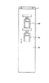
図1乃至図3は、本発明の固体絶縁母線スイッチギヤの実施の形態を示すもので、図1は本発明の固体絶縁母線スイッチギヤの第1の実施の形態を示す縦断側面図、図2は、図1に示す本発明の固体絶縁母線スイッチギヤの正面図、図3は図1に示す本発明の固体絶縁母線スイッチギヤの第1の実施の形態の概略接続図である。
Embodiments of a solid insulated bus switchgear according to the present invention will be described below with reference to the drawings.
1 to 3 show an embodiment of a solid insulated bus switchgear according to the present invention. FIG. 1 is a longitudinal side view showing a first embodiment of a solid insulated bus switchgear according to the present invention. FIG. 3 is a front view of the solid insulated bus switchgear of the present invention shown in FIG. 1, and FIG. 3 is a schematic connection diagram of the first embodiment of the solid insulated bus switchgear of the present invention shown in FIG.
図1乃至図3において、固体絶縁スイッチギヤにおける筺体1は、接地金属板である仕切り板2により正面側と背面側とに仕切られ、背面側(図1の左側)に母線室5が区画形成され、正面側(図1の右側)の上下には、さらに密閉カバー3によって2つの機器室4,4が区画形成されている。筺体1の前面側には、開閉可能な正面扉1Aが設けられ、同様に背面側には、開閉可能な背面扉1Bが設けられている。また、機器室4,4と正面扉1Aの裏側との間には、制御室が区画形成されている。正面扉1Aには、保護制御器16が取り付けられている。
1 to 3, a housing 1 in a solid insulation switchgear is partitioned into a front side and a back side by a
各機器室4,4の底部には、仕切り板2と筺体1の両側面内側とに外周の3辺を固定された略矩形の支持板7,7がそれぞれ配置されている。この支持板7,7の上に2つの開閉器ユニット8,8が、それぞれ載置されている。開閉器ユニット8は、電源回路の電流遮断を行う真空遮断器(VCB)9の遮断部10aと、遮断部10aの開閉操作を行う真空遮断器9の操作器10と、真空遮断器9の負荷側の端子に配置された変流器(CT)11と、真空遮断器10の電源側の端子に配置された零相変流器(ZCT)12と、真空遮断器10の上部に配置された前記いずれかの端子に接続された計器用変圧器(VT)13と、から構成されている。
Substantially
2つの開閉器ユニット8,8は、それぞれの前面側(図1の右側)に正面カバー31を備えている。この正面カバー31には、その上下方向略中央に棒状の引出し取手15が取り付けられている。2つの開閉器ユニット8,8はそれぞれ台車14に搭載されている。また、台車14には、その上部において、真空遮断器9と操作器10の正面側と両側面の3面の外周を覆うようにフレーム17が立設されている。このフレーム17には変流器11、零相変流器12、及び計器用変圧器13が取り付けられている。
The two
上述した開閉器ユニット8を構成する真空遮断器9、変流器11、零相変流器12は、図3に示すように直列に接続されている。零相変流器12は、真空遮断器9の電源側に配置され、変流器11は真空遮断器9の負荷側に配置されている。また、計器用変圧器13は、上段において真空遮断器9の負荷側に接続され、下段において真空遮断器9の電源側に接続されている。
The
開閉器ユニット8の背部には、図3に示すように、真空遮断器9の固定電極側(下側)に接続する端子18と、真空遮断器9の可動電極側(上側)に接続する端子19とが配置されている。これらの端子18,19は、後述する母線室5内の主母線20に接続した連絡母線21,引出し母線22,23に気中断路用ブッシング部を介して接離可能に接続されている。
As shown in FIG. 3, a
図1において、母線室5内には、固体絶縁された主母線20が、筺体1の上下方向略中央部において、筺体1の幅方向に配設されている。この主母線20には、固体絶縁された連絡母線21の一端が接続されている。この連絡母線21の他端は、一方側の接続端子21aと他方側の接続端子21bとに分岐されている。一方側の接続端子21aは、上側の開閉器ユニット8の端子18と接離可能なように機器室4内に導入されている。他方側の接続端子21bは、下側の開閉器ユニット8の端子19と接離可能なように機器室4内に導入されている。これらの接続端子21aと21bは、それぞれ、気中断路用ブッシング部24,25によって、仕切り板2に固定されている。
In FIG. 1, a
母線室4内の上側及び下側には、それぞれ固体絶縁された引出母線22,23が配置されている。上側の引き出し母線22の一端には、接続端子22aが設けられている。この接続端子22aは、上述した上側の開閉器ユニット8の端子19と接離可能なように機器室3内に導入され、気中断路用ブッシング部26によって、仕切り板2に固定されている。上側の引き出し母線22の他端は、ケーブルヘッド28に接続されている。
On the upper side and the lower side in the
下側の引き出し母線23の一端には、接続端子23aが設けられている。この接続端子23aは、上述した下側の開閉器ユニット8の端子18と接離可能なように機器室3内に導入され、気中断路用ブッシング部27によって、仕切り板2に固定されている。下側の引き出し母線23の他端は、ケーブルヘッド28に接続されている。各ケーブルヘッド28,28には、ケーブル29の一端がそれぞれ接続されている。このケーブル29の他端は筺体1の上方に引き出されている。
A
また、主母線20、連絡母線21、引出母線22,23の各表面には接地層が設けられており、感電等に対する安全性が図られていると共に、省メンテナンスであり、保守の省力化が図られている。
In addition, a grounding layer is provided on each surface of the
次に、上述した本発明の固体絶縁母線スイッチギヤを構成する開閉器ユニット8の詳細を図4乃至図6を用いて説明する。図4は、本発明の固体絶縁母線スイッチギヤの第1の実施の形態を構成する開閉器ユニットの斜視図、図5は図4に示す本発明の固体絶縁母線スイッチギヤの第1の実施の形態を構成する開閉器ユニットの側面図、図6は図4に示す本発明の固体絶縁母線スイッチギヤの第1の実施の形態を構成する開閉器ユニットの分解組立を説明する側面図である。
Next, the details of the
図4乃至図6において、図1乃至図3に示す符号と同符号のものは同一部分である。開閉器ユニット8を構成する真空遮断器9は、4個の車輪を有する台車14に搭載されていて、台車の前側に配置されている操作器10と、その後部に配置されていて3個の絶縁筒30からなる遮断部10aとで形成されている。操作器10の前面には、正面カバー31が設けられていて、上下方向略中央には、棒状の引出し取手15が取り付けられている。
4 to 6, the same reference numerals as those shown in FIGS. 1 to 3 denote the same parts. The
真空遮断器9の遮断部10aには、例えば、上側に3個の可動電極側端子19と下側に3個の固定電極側端子18とが水平に取り付けられている。
For example, three movable
フレーム17は、零相変流器12と変流器11とが取り付けられる側板フレーム17aと、計器用変圧器13が取り付けられる正面板フレーム17bと、正面板フレーム17bの上部側面と側板フレーム17aの上部とを連結する連結板フレーム17c,17cとを備えている。これらのフレーム17は、鋼板で形成されているが、例えば繊維強化プラスチックFRP(Fiber Reinforced Plastics)や鋼板以外の金属板で形成してもよい。
The
側板フレーム17aは、半楕円形の切り欠き36を上下方向に2箇所設けた略矩形の2枚の側板37,37を、台車14の幅方向と略等しい間隔で対向させ、側板37,37の上角部と下角部をそれぞれ変流器取付け部材35,35で連結することで形成されている。この側板フレーム17aに設けた合計4個の切り欠き36は、真空遮断器9の外周にフレーム17を設けたことによる絶縁性能の低下を回避するために設けたものである。また、上側の変流器取付け部材35には、3相の内の2相の可動電極側端子19をそれぞれ覆う変流器11,11がボルトで締め付けて取り付けられている。下側の変流器取付け部材35には、1個の鉄心で3相の固定電極側端子18を覆うレーストラック型の零相変流器12がボルトで締め付けて取り付けられている。さらに、側板フレーム17aの側板37,37の正面側上部において、開閉器ユニット8内側方向に取付けフランジ部40aが形成されていて、取付孔が設けられている。
The
正面板フレーム17bは、計器用変圧器13がボルトで締め付けて固定される略矩形の正面板部38と、この正面板部38の両側部で操作器10の上部にボルト締めされる側面視略長方形の支持板部39,39とで形成されている。支持板部39,39には、後述する連結板フレーム17c,17cと連結するための取付孔が設けられている。
The
連結板フレーム17c,17cは、図4に示すように、側面視台形で上方視略コ字状の鋼板であって、台形状の側板の底部には、側板フレーム17a取付孔が設けられたフランジ部40bが形成されている。他方の側板には、正面板フレーム17b取付孔が設けられている。
As shown in FIG. 4, the connecting plate frames 17 c and 17 c are steel plates having a trapezoidal shape in a side view and a substantially U-shape in an upper view, and a flange having a
計器用変圧器13は、単相変圧器13a2個を併設し、可動電極側端子19とV/V結線で回路を構成している。ここで、単相変圧器13a,13aは樹脂モールド形で、その本体の上部(図4及び図6においては、左側部)には、主回路端子(一次側端子)13b、一次側の保護ヒューズ13cを、本体の側部(図4及び図6においては、上側部)には二次端子13dを備え、台座13eを介して正面板フレーム17bに固定されている。また、図4に示すように、主回路端子13bは、接続線34により、真空遮断器9の遮断部10aにある上側の可動電極側端子19と接続されている。
The
次に、本発明の固体絶縁母線スイッチギヤの第1の実施の形態における開閉器ユニット8の組み立て方法を図6を用いて説明する。まず、図6の(a)の上側において、計器用変圧器13と、接続線34と、正面板フレーム17bと、支持板フレーム17cとの分解状態、図6の(a)の下左側に、変流器11と、零相変流器12と、側板フレーム17aとの分解状態、図6の(a)の下右側に、台車14の上に搭載された操作器10と遮断部10aとからなる真空遮断器9の組み立て状態とを、それぞれ示している。つまり、開閉器ユニット8は大略3個の構成部に分けることができ、この各構成部をそれぞれ組み立てた後に、各構成部を連結することで全体を組立てることになる。
Next, a method of assembling the
図6の(b)の上側において、計器用変圧器13は、正面板フレーム17bに台座13eを介してボルトで固定されている。正面板フレーム17bと連結板フレーム17c,17cの連結は、正面板フレーム17bの支持板部39,39に形成された取付孔を、連結板フレーム17c,17cの他方の側板に形成された取付孔と合わせ、取付ボルトを嵌挿し締結することで行われる。
On the upper side of FIG. 6B, the
次に、上述した正面板フレーム17bの支持板部39,39の底部と操作器10の上部をボルトで締めることにより、正面板フレーム17bを操作器10に固定設置する。また、計器用変圧器13の主回路端子13bを接続線34により、真空遮断器9の遮断部10aにある上側の可動電極側端子19と接続する。
Next, the
次に、側板フレーム17aを取り付ける。具体的には、変流器11,11及び零相変流器12が、所定の電極端子を覆うように台車14に側板フレーム17aを嵌挿し、側板フレーム17aの側板37,37下部を台車14にボルトで締め付けて固定する。また、側板フレーム17aと連結板フレーム17c,17cの連結は、上述した側板フレーム17aのフランジ部40a,40aに形成された取付孔を、連結フレーム17c,17cのフランジ部40b,40bに形成された取付孔と合わせ、取付ボルトを嵌挿し締結することで行われる。このようにして組立完了した開閉器ユニット8の側面図を図5に示す。
Next, the
上述した本発明の固体絶縁母線スイッチギヤの第1の実施の形態によれば、真空遮断器9と計器用変圧器13とを同一の開閉器ユニット8に配設したので、受配電用スイッチギヤの段積み構成で従来2段必要であった遮断器と計器用変圧器との並列回路を1段で構成することができる。
According to the first embodiment of the solid insulated bus switchgear of the present invention described above, since the
また、固体絶縁された主母線20、連絡母線21、引出母線22、23を、機器室4の背部の母線室5に配置構成して、これら母線間の絶縁距離を縮小したので、収納空間が小さくなり、スイッチギヤ全体を小型化することができる。このことにより、列盤構成時の盤面数を大幅に削減することができ、列盤構成の受配電スイッチギヤの設置面積を縮小することができる。
In addition, the
さらに、フレーム17に変流器11、零相変流器12、計器用変圧器13を取り付けた後に、このフレーム17を台車14に搭載された真空遮断器9と操作器10の外周に取り付ける構造となっている。このため、例えば事故時に真空遮断器9を交換する場合、筺体1から引き出し、フレーム17を取り外し、新しい真空遮断器9にフレーム17を取り付けることで交換作業が完了する。このように、事故時の復旧作業が簡素化されるとともに、作業時間を短縮化することができる。
Further, a structure in which the
また、フレーム17の両側面の変流器11及び零相変流器12に対応する部分には、半楕円の切り欠き36,36を形成したことにより、開閉器ユニット8の絶縁性能を確保している。このフレーム17に計器用変圧器13を固定することで、真空遮断器9と計器油変圧器13とを同一ユニットに搭載することができる。
Further, the portions corresponding to the
さらに、真空遮断器9の電源側に零相変流器12を配置しているので、真空遮断器9を含めた負荷側全体の地絡保護を行える。この結果、保護範囲を拡大させることができる。
Further, since the zero-phase
なお、本発明の実施の形態においては、真空遮断器9の電源側端子に零相変流器を配置し、負荷側端子に変流器11を配置したが、この態様に限られるものではない。負荷側端子に零相変流器12、電源側端子に変流器11を配置してもよい。
In the embodiment of the present invention, the zero-phase current transformer is arranged at the power supply side terminal of the
次に、本発明の固体絶縁母線スイッチギヤの第2の実施の形態を図7乃至図10を用いて説明する。図7は本発明の固体絶縁母線スイッチギヤの第2の実施の形態の縦断側面図、図8は図7に示す本発明の固体絶縁母線スイッチギヤの一部断面にて示す背面図、図9は図7に示す本発明の固体絶縁母線スイッチギヤの第2の実施の形態の概略接続図、図10は一般的な受配電スイッチギヤの従来例における概略接続図である。なお、以下の説明において、上述した本発明の第1の実施の形態と同じ構成要素には同一の符合を付し、その部分の説明は省略する。 Next, a second embodiment of the solid insulated bus switchgear according to the present invention will be described with reference to FIGS. FIG. 7 is a longitudinal side view of a second embodiment of the solid insulated bus switchgear of the present invention, FIG. 8 is a rear view showing a partial cross section of the solid insulated bus switchgear of the present invention shown in FIG. Is a schematic connection diagram of the second embodiment of the solid insulated bus switchgear of the present invention shown in FIG. 7, and FIG. 10 is a schematic connection diagram of a conventional example of a general power receiving and distributing switchgear. In the following description, the same components as those in the first embodiment of the present invention described above are denoted by the same reference numerals, and description thereof is omitted.
まず、図10は、一般的な受配電スイッチギヤの従来例であって、機器ユニットを上下に2段搭載した筺体100と101の2面とからなる列盤で構成されている。筺体100の上段には、真空遮断器9、この真空遮断器9の固定電極及び可動電極側に設けられた断路部80、真空遮断器9の負荷側に設けられた零相変流器12、及び真空遮断器9の電源側に設けられた変流器11とからなる機器ユニット102が搭載され、下段には、計器用変圧器81と断路部80とからなる機器ユニット102が搭載されている。また、筺体101の上段には、前記筺体100の上段に搭載された機器ユニット102と同じ構成の機器ユニット102が搭載され、下段には、計器用変圧器81と、断路部80と、気中断路器82とからなる機器ユニット102が搭載されている。この筺体100の右側に筺体101が並置され、主母線20が両筺体を貫通して設けられている。主母線20は、2つの真空遮断器9、9の可動側電極に設けられた断路部80、80を介して接離可能に接続している。
First, FIG. 10 shows a conventional example of a general power receiving / distributing switch gear, which is composed of a row of
次に、この一般的な受配電スイッチギヤの回路構成と等価の回路を、本発明の固定絶縁母線スイッチギヤで構成したのが、本発明の第2の実施の形態である。本実施の形態における固体絶縁母線スイッチギヤは、上記第1の実施の形態における固体絶縁母線スイッチギヤと以下の点でその形態が異なり、その他の点は共通する。 Next, a circuit equivalent to the circuit configuration of this general power receiving / distributing switchgear is configured by the fixed insulated bus switchgear of the present invention in the second embodiment of the present invention. The form of the solid insulated bus switchgear in the present embodiment is different from the solid insulated bus switchgear in the first embodiment in the following points, and the other points are common.
(1)図7に示すように、本実施の形態においては、仕切り板2と密閉カバー3で区画形成される機器室4が上下方向に3段に構成されている。したがって、各機器室4に搭載される開閉器ユニット8も合計で3ユニット必要となる。この3つの開閉器ユニット8は、図9で示すように、上段の開閉器ユニット8は、真空遮断器9と、この真空遮断器9の固定電極及び可動電極側に設けられた断路部80と、真空遮断器9の負荷側に設けられた変流器11と、真空遮断器9の電源側に設けられた零相変流器12と、計器用変圧器13とを備え、中段の開閉器ユニット8は、真空遮断器9と、この真空遮断器9の固定電極及び可動電極側に設けられた断路部80と、真空遮断器9の電源側に設けられた変流器11と、真空遮断器9の負荷側に設けられた零相変流器12とを備え、下段の開閉器ユニット8は、真空断路器32と、この真空断路器32の固定電極及び可動電極側に設けられた断路部80と、計器要変圧器13とを備えている。
(1) As shown in FIG. 7, in the present embodiment, the
(2)図7において、母線室5内には、上段の機器室4の背面側と中段の機器室4の背面側の位置に、筺体1の幅方向に固体絶縁された主母線20が配設されている。この主母線20には、固体絶縁された連絡母線21の一端が接続されている。この連絡母線21の他端は、一方側の接続端子21aと他方側の接続端子21bとに分岐されている。一方側の接続端子21aは、上段の開閉器ユニット8の下側端子18と接離可能なように機器室4内に導入されている。他方側の接続端子21bは、中段の開閉器ユニット8の上側端子19と接離可能なように機器室4内に導入されている。また、中段の開閉器ユニット8の下側端子18と下段の開閉器ユニット8の上側端子19と接離可能なように補助連絡母線33の接続端子33aと33bがそれぞれ機器室4内に導入されている。図8は、これら固体絶縁された主母線20、連絡母線21、引出母線22、23、補助連絡母線33と各機器室4の背面部との接続配置状態を示している。
(2) In FIG. 7, a
上述した本発明の固体絶縁母線スイッチギヤの第2の実施の形態によれば、上述した第1の実施の形態と同様な効果を得ることができるとともに、従来の受配電スイッチギヤの2段積み2面の列盤で構成していた計器用変圧器13を含む一般的な受配電回路構成を、3段積み1面で構成することができる。このことにより、列盤構成時の盤面数を大幅に削減することができ、列盤構成の受配電スイッチギヤの設置面積を大幅に縮小することができる。
According to the second embodiment of the solid insulated bus switchgear of the present invention described above, the same effects as those of the first embodiment described above can be obtained, and two-stage stacking of the conventional power distribution switchgear can be achieved. A general power receiving / distributing circuit configuration including the
また、フレーム17に、変流器11、零相変流器12、計器用変圧器13を取り付けた後に、このフレーム17を台車14に搭載された真空遮断器9等の外周に取り付ける構造となっている。このため、変流器11等の各機器の取付けの要否や、配置場所を簡単に変更することができる。つまり、部品の共通性と組み立ての容易性が図れることにより、生産コストを減少することができる。
In addition, after the
なお、上述した本発明の実施の形態においては、ケーブル29を筺体1の上方に引き出すようにしたが、下方側に引き出すことも可能である。
In the above-described embodiment of the present invention, the
1 筺体
1A 正面扉
1B 背面扉
2 仕切板
3 密閉カバー
4 機器室
5 母線室
6 制御室
7 支持板
8 開閉器ユニット
9 真空遮断器
10 操作器
11 変流器
12 零相変流器
13 計器用変圧器
14 台車
17 フレーム
18 固定電極側端子
19 可動電極側端子
20 主母線
21 連絡母線
22 引出母線
23 引出母線
36 切り欠き
DESCRIPTION OF SYMBOLS 1
Claims (3)
前記筐体の機器室内に、前記筺体の上下方向に積載配置される遮断器、変流器、零相変流器、及び計器用変圧器からなる開閉器ユニットと、
前記筐体の母線室内に、前記筺体の幅方向に配置される固体絶縁された主母線と、該主母線に連結され前記開閉器ユニットの一方側にそれぞれ接続される固体絶縁された連絡母線と、前記開閉器ユニットの他方側にそれぞれ接続される固体絶縁された引出し母線とを備え、
前記開閉器ユニットは、移動可能な台車と、この台車上に設置した前記遮断器と、前記遮断器の正面側と両側面の3面の外周を覆うように前記台車上部に立設され、前記変流器、零相変流器、計器用変圧器を取り付けたフレームとを有し、前記遮断器の背面部には、該遮断器の固定電極側に接続する端子と可動電極側に接続する端子が上下いずれかに配置され、該端子が前記筺体に設けられた気中ブッシング部を介して前記連絡母線及び引出し母線と接離可能に接続され、
前記変流器が前記遮断器の3相の負荷側の端子における2相の端子を覆うように前記フレームに固定され、前記零相変流器が前記遮断器の3相の電源側の端子を覆うように前記フレームに固定され、前記計器用変圧器が前記遮断器の3相の負荷側または電源側のいずれか一方の端子とヒューズを介して接続され、前記フレームの両側面の前記変流器及び零相変流器に対応する部分には、絶縁性能を保つために、半楕円の切り欠きを形成したことを特徴とする固体絶縁母線スイッチギヤ。 A housing having an equipment room defined on the front side by a ground metal plate and a bus room defined on the back side;
A switch unit comprising a circuit breaker, a current transformer, a zero-phase current transformer, and a meter transformer, which are stacked in the vertical direction of the housing in the equipment room of the housing;
A solid-insulated main bus arranged in the width direction of the housing within the bus-bar chamber of the housing, and a solid-insulated connecting bus connected to the main bus and connected to one side of the switch unit; A solid insulated drawer bus connected to the other side of the switch unit,
The switch unit is erected on the top of the carriage so as to cover a movable carriage, the breaker installed on the carriage, and the outer periphery of the three surfaces of the front and both sides of the breaker, A current transformer, a zero-phase current transformer, and a frame to which an instrument transformer is attached. A terminal connected to the fixed electrode side of the circuit breaker and a movable electrode side are connected to the back surface of the circuit breaker. A terminal is disposed on either the upper or lower side, and the terminal is connected to the connection bus bar and the lead bus bar through an air bushing portion provided in the housing so as to be contactable and separable .
The current transformer is fixed to the frame so as to cover the two-phase terminals of the three-phase load side terminals of the circuit breaker, and the zero-phase current transformer is connected to the three-phase power supply side terminals of the circuit breaker. The instrument transformer is fixed to the frame so as to cover, and the current transformer on both sides of the frame is connected to one of the three-phase load side or power source terminal of the circuit breaker via a fuse. A solid-insulated bus switchgear characterized in that a semi-elliptical notch is formed in a portion corresponding to the transformer and the zero-phase current transformer in order to maintain insulation performance .
前記筐体の機器室内に、前記筺体の上下方向の各段に積載配置される遮断器、変流器、零相変流器、及び計器用変圧器からなる上段の開閉器ユニットと、遮断器、変流器、及び零相変流器からなる中段の開閉器ユニットと、断路器、及び計器用変圧器からなる下段の開閉器ユニットと、
前記筐体の母線室内に、前記筺体の幅方向に配置される固体絶縁された主母線と、該主母線に連結され前記上段と前記中段の開閉器ユニットの一方側にそれぞれ接続される固体絶縁された連絡母線と、前記中段の開閉器ユニットの他方側と前記下段の開閉器ユニットの一方側とを接続する固体絶縁された補助連絡母線と、前記上段と前記下段の開閉器ユニットの他方側にそれぞれ接続される固体絶縁された引出し母線とを備え、
前記上中下段の各開閉器ユニットは、移動可能な台車と、この台車上に設置した前記遮断器または前記断路器と、前記遮断器または前記断路器の正面側と両側面の3面の外周を覆うように前記台車上部に立設され、前記変流器、零相変流器、計器用変圧器の少なくとも1つの機器が取り付けられたフレームとを有し、前記遮断器または断路器の背面部には、該遮断器または断路器の固定電極側に接続する端子と可動電極側に接続する端子が上下いずれかに配置され、該端子が前記筺体に設けられた気中ブッシング部を介して前記連絡母線、補助連絡母線、及び引出し母線と接離可能に接続されることを特徴とする固体絶縁母線スイッチギヤ。 A housing having an equipment room defined on the front side by a ground metal plate and a bus room defined on the back side;
An upper switch unit comprising a circuit breaker, a current transformer, a zero-phase current transformer, and an instrument transformer, which are loaded and arranged on each stage in the vertical direction of the casing in the equipment room of the housing; and a circuit breaker. A middle-stage switch unit composed of a current transformer and a zero-phase current transformer, and a lower-stage switch unit composed of a disconnector and an instrument transformer,
A solid-insulated main bus arranged in the width direction of the housing in the bus bar chamber of the housing, and a solid insulation connected to one side of the upper and middle switch units connected to the main bus. A connected solid bus, a solid-insulated auxiliary communication bus connecting the other side of the middle switch unit and one side of the lower switch unit, and the other side of the upper and lower switch units A solid insulated drawer bus connected to each of the
Each of the upper, middle, and lower switch units includes a movable carriage, the circuit breaker or disconnector installed on the carriage, and the outer periphery of the front and both sides of the breaker or disconnector. And a frame on which at least one device of the current transformer, the zero-phase current transformer, and the instrument transformer is attached, and is installed on the top of the carriage so as to cover the back of the circuit breaker or disconnector In the part, a terminal connected to the fixed electrode side of the circuit breaker or disconnector and a terminal connected to the movable electrode side are arranged either up or down, and the terminal is connected through an air bushing provided in the housing A solid insulated bus switchgear that is connected to the connecting bus, the auxiliary connecting bus, and the lead-out bus so as to be able to contact and separate.
前記下段の開閉器ユニットの断路器は、真空断路器であることを特徴とする固体絶縁母線スイッチギヤ。 The solid insulated bus switchgear according to claim 2 ,
A solid insulated bus switchgear, wherein the disconnector of the lower switch unit is a vacuum disconnector.
Priority Applications (7)
| Application Number | Priority Date | Filing Date | Title |
|---|---|---|---|
| JP2008176665A JP4633145B2 (en) | 2008-07-07 | 2008-07-07 | Solid insulated busbar switchgear |
| TW098115677A TWI434480B (en) | 2008-07-07 | 2009-05-12 | Solid state insulated busbar gear switch |
| EP09008265.2A EP2144343B1 (en) | 2008-07-07 | 2009-06-24 | Solid insulated bus switchgear |
| SG200904428-0A SG158059A1 (en) | 2008-07-07 | 2009-06-29 | Solid insulated bus switchgear |
| US12/496,033 US8045322B2 (en) | 2008-07-07 | 2009-07-01 | Solid insulated bus switchgear |
| CN2009101517118A CN101626149B (en) | 2008-07-07 | 2009-07-06 | Solid insulated bus switchgear |
| KR1020090061289A KR101030290B1 (en) | 2008-07-07 | 2009-07-06 | Solid insulated bus switchgear |
Applications Claiming Priority (1)
| Application Number | Priority Date | Filing Date | Title |
|---|---|---|---|
| JP2008176665A JP4633145B2 (en) | 2008-07-07 | 2008-07-07 | Solid insulated busbar switchgear |
Publications (2)
| Publication Number | Publication Date |
|---|---|
| JP2010017051A JP2010017051A (en) | 2010-01-21 |
| JP4633145B2 true JP4633145B2 (en) | 2011-02-16 |
Family
ID=41268250
Family Applications (1)
| Application Number | Title | Priority Date | Filing Date |
|---|---|---|---|
| JP2008176665A Active JP4633145B2 (en) | 2008-07-07 | 2008-07-07 | Solid insulated busbar switchgear |
Country Status (7)
| Country | Link |
|---|---|
| US (1) | US8045322B2 (en) |
| EP (1) | EP2144343B1 (en) |
| JP (1) | JP4633145B2 (en) |
| KR (1) | KR101030290B1 (en) |
| CN (1) | CN101626149B (en) |
| SG (1) | SG158059A1 (en) |
| TW (1) | TWI434480B (en) |
Families Citing this family (24)
| Publication number | Priority date | Publication date | Assignee | Title |
|---|---|---|---|---|
| JP5026537B2 (en) * | 2010-02-03 | 2012-09-12 | 株式会社日立製作所 | Switchgear |
| US8733855B2 (en) * | 2010-07-13 | 2014-05-27 | Siemens Industry, Inc. | Arc resistant switchgear modular compartment for instrumentation and circuit breakers |
| JP5181003B2 (en) | 2010-08-23 | 2013-04-10 | 株式会社日立製作所 | Switchgear |
| JP5211147B2 (en) | 2010-12-20 | 2013-06-12 | 株式会社日立製作所 | Switchgear |
| CN102361245A (en) * | 2011-07-12 | 2012-02-22 | 北京龙源开关设备有限责任公司 | Handcart type breaker for inflation switch cabinet |
| EP2738893B1 (en) | 2011-07-29 | 2017-02-01 | Mitsubishi Electric Corporation | Closed distribution panel |
| KR101247538B1 (en) * | 2011-12-06 | 2013-03-26 | 인텍전기전자 주식회사 | Solid insulated switchgear |
| JP2013158220A (en) * | 2012-01-31 | 2013-08-15 | Toshiba Corp | Solid insulation switch gear |
| KR101279894B1 (en) * | 2012-04-03 | 2013-06-28 | 엘에스산전 주식회사 | Switch for solid insulated switchgear |
| CN205212301U (en) * | 2012-12-28 | 2016-05-04 | Abb技术有限公司 | Switchgear |
| KR101324731B1 (en) * | 2013-02-01 | 2013-11-05 | 노신정 | Load breaker switchgear and package panel switchgear having the same |
| US9847163B2 (en) * | 2013-10-30 | 2017-12-19 | Mitsubishi Elctric Corporation | Current transformer support device and switchgear using current transformer support device |
| CN103633575B (en) * | 2013-12-12 | 2016-07-06 | 中国船舶重工集团公司第七0四研究所 | Marine medium-voltage power distribution unit |
| US10050420B1 (en) * | 2017-02-14 | 2018-08-14 | Eaton Intelligent Power Limited | Conversion system for a switchgear assembly |
| CN107959256A (en) * | 2017-03-24 | 2018-04-24 | 天津市先智电气设备有限公司 | Intensive dual-power transfer switch |
| WO2018232236A1 (en) | 2017-06-16 | 2018-12-20 | Eaton Intelligent Power Limited | Isolating gas-insulated bus arrangements for switchgear |
| US10164412B1 (en) * | 2017-06-16 | 2018-12-25 | Eaton Intelligent Power Limited | Switchgear with a two-high circuit interrupter configuration |
| WO2018232246A1 (en) | 2017-06-16 | 2018-12-20 | Eaton Intelligent Power Limited | Isolating bus enclosure arrangements for switchgear |
| US10158214B1 (en) | 2017-06-16 | 2018-12-18 | Eaton Intelligent Power Limited | Switchgear with modular bus configuration supporting individual and parallel feed arrangements |
| CN208208646U (en) * | 2018-05-21 | 2018-12-07 | 山东泰开成套电器有限公司 | A kind of novel indoor high-voltage intelligent vacuum circuit breaker |
| KR102163626B1 (en) * | 2018-11-21 | 2020-10-08 | 주식회사 대홍전기 | Drawn module for mcsg |
| JP7248197B2 (en) * | 2020-08-05 | 2023-03-29 | 三菱電機株式会社 | control center |
| US11735385B2 (en) * | 2021-02-25 | 2023-08-22 | Jst Power Equipment, Inc. | Medium-voltage switchgear system having single phase breaker control |
| CN115275850B (en) * | 2022-08-10 | 2023-09-01 | 浙江聚盛电气股份有限公司 | Switch cabinet valve driving mechanism with self-locking function |
Citations (10)
| Publication number | Priority date | Publication date | Assignee | Title |
|---|---|---|---|---|
| JPS54103522A (en) * | 1978-02-01 | 1979-08-15 | Mitsubishi Electric Corp | Enclosed switchboards |
| JPH0169304U (en) * | 1987-10-23 | 1989-05-09 | ||
| JPH0746726A (en) * | 1993-07-29 | 1995-02-14 | Toshiba Corp | Metal-clad switchgear |
| JPH07322422A (en) * | 1994-05-20 | 1995-12-08 | Mitsubishi Electric Corp | Enclosed switchboard |
| JPH0946829A (en) * | 1995-07-28 | 1997-02-14 | Fuji Electric Co Ltd | Bus bushing of double-layer breaker |
| JPH11341625A (en) * | 1998-05-22 | 1999-12-10 | Mitsubishi Electric Corp | Unit truck |
| JP2006081385A (en) * | 2004-08-10 | 2006-03-23 | Hitachi Electric Systems Ltd | Switchgear for distributing electric power |
| JP2007336658A (en) * | 2006-06-14 | 2007-12-27 | Mitsubishi Electric Corp | Switchgear |
| JP2008043181A (en) * | 2006-07-10 | 2008-02-21 | Hitachi Ltd | Opening/closing device for power distribution |
| JP2008067596A (en) * | 2004-08-10 | 2008-03-21 | Hitachi Electric Systems Ltd | Switchgear for power distribution |
Family Cites Families (10)
| Publication number | Priority date | Publication date | Assignee | Title |
|---|---|---|---|---|
| AU3060977A (en) * | 1976-12-14 | 1979-05-24 | Tokyo Shibaura Electric Co | Enclosure for electrical apparatus |
| US4146915A (en) * | 1976-12-16 | 1979-03-27 | Tokyo Shibaura Denki Kabushiki Kaisha | Shutter mechanism for an enclosed electrical switchboard |
| US4351990A (en) * | 1980-08-01 | 1982-09-28 | Westinghouse Electric Corp. | Interphase barrier for switchgear |
| JPS58186303A (en) * | 1982-04-23 | 1983-10-31 | 株式会社日立製作所 | Switchboard |
| JPS6469304A (en) | 1987-09-09 | 1989-03-15 | Sharp Kk | Cleaving device |
| JP3820809B2 (en) * | 1999-07-27 | 2006-09-13 | 三菱電機株式会社 | Switchgear disconnecting device |
| JP4329923B2 (en) | 2002-10-31 | 2009-09-09 | 三菱電機株式会社 | Gas insulated switchgear |
| JP2007014087A (en) * | 2005-06-29 | 2007-01-18 | Hitachi Ltd | Vacuum insulation switchgear |
| TW200814480A (en) * | 2006-07-10 | 2008-03-16 | Hitachi Ltd | Distribution switchgear |
| TWI416830B (en) * | 2007-12-18 | 2013-11-21 | Hitachi Ltd | Switchboard |
-
2008
- 2008-07-07 JP JP2008176665A patent/JP4633145B2/en active Active
-
2009
- 2009-05-12 TW TW098115677A patent/TWI434480B/en not_active IP Right Cessation
- 2009-06-24 EP EP09008265.2A patent/EP2144343B1/en not_active Not-in-force
- 2009-06-29 SG SG200904428-0A patent/SG158059A1/en unknown
- 2009-07-01 US US12/496,033 patent/US8045322B2/en not_active Expired - Fee Related
- 2009-07-06 KR KR1020090061289A patent/KR101030290B1/en not_active IP Right Cessation
- 2009-07-06 CN CN2009101517118A patent/CN101626149B/en not_active Expired - Fee Related
Patent Citations (10)
| Publication number | Priority date | Publication date | Assignee | Title |
|---|---|---|---|---|
| JPS54103522A (en) * | 1978-02-01 | 1979-08-15 | Mitsubishi Electric Corp | Enclosed switchboards |
| JPH0169304U (en) * | 1987-10-23 | 1989-05-09 | ||
| JPH0746726A (en) * | 1993-07-29 | 1995-02-14 | Toshiba Corp | Metal-clad switchgear |
| JPH07322422A (en) * | 1994-05-20 | 1995-12-08 | Mitsubishi Electric Corp | Enclosed switchboard |
| JPH0946829A (en) * | 1995-07-28 | 1997-02-14 | Fuji Electric Co Ltd | Bus bushing of double-layer breaker |
| JPH11341625A (en) * | 1998-05-22 | 1999-12-10 | Mitsubishi Electric Corp | Unit truck |
| JP2006081385A (en) * | 2004-08-10 | 2006-03-23 | Hitachi Electric Systems Ltd | Switchgear for distributing electric power |
| JP2008067596A (en) * | 2004-08-10 | 2008-03-21 | Hitachi Electric Systems Ltd | Switchgear for power distribution |
| JP2007336658A (en) * | 2006-06-14 | 2007-12-27 | Mitsubishi Electric Corp | Switchgear |
| JP2008043181A (en) * | 2006-07-10 | 2008-02-21 | Hitachi Ltd | Opening/closing device for power distribution |
Also Published As
| Publication number | Publication date |
|---|---|
| EP2144343B1 (en) | 2016-10-26 |
| JP2010017051A (en) | 2010-01-21 |
| SG158059A1 (en) | 2010-01-29 |
| CN101626149A (en) | 2010-01-13 |
| KR20100005684A (en) | 2010-01-15 |
| US8045322B2 (en) | 2011-10-25 |
| TW201010221A (en) | 2010-03-01 |
| KR101030290B1 (en) | 2011-04-19 |
| US20100002363A1 (en) | 2010-01-07 |
| CN101626149B (en) | 2012-05-23 |
| EP2144343A2 (en) | 2010-01-13 |
| TWI434480B (en) | 2014-04-11 |
| EP2144343A3 (en) | 2012-08-15 |
Similar Documents
| Publication | Publication Date | Title |
|---|---|---|
| JP4633145B2 (en) | Solid insulated busbar switchgear | |
| JP4727736B2 (en) | Switchgear | |
| EP2485348B1 (en) | Switchgear | |
| EP2017866B1 (en) | Vacuum insulated switchgear | |
| JP4268991B2 (en) | Vacuum insulated switchgear | |
| US7440260B2 (en) | Electrical bus member mounting system and electrical enclosure employing the same | |
| KR20080005869A (en) | Switching device for power distribution | |
| JP5026537B2 (en) | Switchgear | |
| EP1983625A1 (en) | Removable compartment for use in a functional unit of an electrical switchgear | |
| JP4333774B2 (en) | Switchgear for power distribution | |
| JP5275263B2 (en) | Switchgear system | |
| US8379373B2 (en) | Vacuum insulated switchgear including a bus recovery member | |
| KR101145723B1 (en) | Metal Clad Switch-Gear/Cubicle | |
| JP5123894B2 (en) | Vacuum insulated switchgear | |
| EP2670008B1 (en) | Vacuum insulation switchgear and method for replacing mold switch | |
| KR101237875B1 (en) | Power receiving and distributing board | |
| JPH0620328B2 (en) | Gas insulated switchgear | |
| JP5013946B2 (en) | Switchgear | |
| JPH1118220A (en) | Gas insulating switch gear |
Legal Events
| Date | Code | Title | Description |
|---|---|---|---|
| A621 | Written request for application examination |
Free format text: JAPANESE INTERMEDIATE CODE: A621 Effective date: 20100430 |
|
| A977 | Report on retrieval |
Free format text: JAPANESE INTERMEDIATE CODE: A971007 Effective date: 20100816 |
|
| A131 | Notification of reasons for refusal |
Free format text: JAPANESE INTERMEDIATE CODE: A131 Effective date: 20100831 |
|
| A521 | Request for written amendment filed |
Free format text: JAPANESE INTERMEDIATE CODE: A523 Effective date: 20101013 |
|
| TRDD | Decision of grant or rejection written | ||
| A01 | Written decision to grant a patent or to grant a registration (utility model) |
Free format text: JAPANESE INTERMEDIATE CODE: A01 Effective date: 20101109 |
|
| A01 | Written decision to grant a patent or to grant a registration (utility model) |
Free format text: JAPANESE INTERMEDIATE CODE: A01 |
|
| A61 | First payment of annual fees (during grant procedure) |
Free format text: JAPANESE INTERMEDIATE CODE: A61 Effective date: 20101116 |
|
| R150 | Certificate of patent or registration of utility model |
Ref document number: 4633145 Country of ref document: JP Free format text: JAPANESE INTERMEDIATE CODE: R150 Free format text: JAPANESE INTERMEDIATE CODE: R150 |
|
| FPAY | Renewal fee payment (event date is renewal date of database) |
Free format text: PAYMENT UNTIL: 20131126 Year of fee payment: 3 |
|
| S111 | Request for change of ownership or part of ownership |
Free format text: JAPANESE INTERMEDIATE CODE: R313111 |
|
| R350 | Written notification of registration of transfer |
Free format text: JAPANESE INTERMEDIATE CODE: R350 |