JP4631396B2 - Backlight unit and liquid crystal display device using the same - Google Patents
Backlight unit and liquid crystal display device using the same Download PDFInfo
- Publication number
- JP4631396B2 JP4631396B2 JP2004318076A JP2004318076A JP4631396B2 JP 4631396 B2 JP4631396 B2 JP 4631396B2 JP 2004318076 A JP2004318076 A JP 2004318076A JP 2004318076 A JP2004318076 A JP 2004318076A JP 4631396 B2 JP4631396 B2 JP 4631396B2
- Authority
- JP
- Japan
- Prior art keywords
- frame
- backlight unit
- side wall
- support frame
- liquid crystal
- Prior art date
- Legal status (The legal status is an assumption and is not a legal conclusion. Google has not performed a legal analysis and makes no representation as to the accuracy of the status listed.)
- Active
Links
Images


Classifications
-
- G—PHYSICS
- G02—OPTICS
- G02F—OPTICAL DEVICES OR ARRANGEMENTS FOR THE CONTROL OF LIGHT BY MODIFICATION OF THE OPTICAL PROPERTIES OF THE MEDIA OF THE ELEMENTS INVOLVED THEREIN; NON-LINEAR OPTICS; FREQUENCY-CHANGING OF LIGHT; OPTICAL LOGIC ELEMENTS; OPTICAL ANALOGUE/DIGITAL CONVERTERS
- G02F1/00—Devices or arrangements for the control of the intensity, colour, phase, polarisation or direction of light arriving from an independent light source, e.g. switching, gating or modulating; Non-linear optics
- G02F1/01—Devices or arrangements for the control of the intensity, colour, phase, polarisation or direction of light arriving from an independent light source, e.g. switching, gating or modulating; Non-linear optics for the control of the intensity, phase, polarisation or colour
- G02F1/13—Devices or arrangements for the control of the intensity, colour, phase, polarisation or direction of light arriving from an independent light source, e.g. switching, gating or modulating; Non-linear optics for the control of the intensity, phase, polarisation or colour based on liquid crystals, e.g. single liquid crystal display cells
- G02F1/133—Constructional arrangements; Operation of liquid crystal cells; Circuit arrangements
- G02F1/1333—Constructional arrangements; Manufacturing methods
- G02F1/1335—Structural association of cells with optical devices, e.g. polarisers or reflectors
-
- G—PHYSICS
- G02—OPTICS
- G02B—OPTICAL ELEMENTS, SYSTEMS OR APPARATUS
- G02B6/00—Light guides; Structural details of arrangements comprising light guides and other optical elements, e.g. couplings
- G02B6/0001—Light guides; Structural details of arrangements comprising light guides and other optical elements, e.g. couplings specially adapted for lighting devices or systems
- G02B6/0011—Light guides; Structural details of arrangements comprising light guides and other optical elements, e.g. couplings specially adapted for lighting devices or systems the light guides being planar or of plate-like form
- G02B6/0081—Mechanical or electrical aspects of the light guide and light source in the lighting device peculiar to the adaptation to planar light guides, e.g. concerning packaging
-
- G—PHYSICS
- G02—OPTICS
- G02F—OPTICAL DEVICES OR ARRANGEMENTS FOR THE CONTROL OF LIGHT BY MODIFICATION OF THE OPTICAL PROPERTIES OF THE MEDIA OF THE ELEMENTS INVOLVED THEREIN; NON-LINEAR OPTICS; FREQUENCY-CHANGING OF LIGHT; OPTICAL LOGIC ELEMENTS; OPTICAL ANALOGUE/DIGITAL CONVERTERS
- G02F1/00—Devices or arrangements for the control of the intensity, colour, phase, polarisation or direction of light arriving from an independent light source, e.g. switching, gating or modulating; Non-linear optics
- G02F1/01—Devices or arrangements for the control of the intensity, colour, phase, polarisation or direction of light arriving from an independent light source, e.g. switching, gating or modulating; Non-linear optics for the control of the intensity, phase, polarisation or colour
- G02F1/13—Devices or arrangements for the control of the intensity, colour, phase, polarisation or direction of light arriving from an independent light source, e.g. switching, gating or modulating; Non-linear optics for the control of the intensity, phase, polarisation or colour based on liquid crystals, e.g. single liquid crystal display cells
- G02F1/133—Constructional arrangements; Operation of liquid crystal cells; Circuit arrangements
- G02F1/1333—Constructional arrangements; Manufacturing methods
- G02F1/133308—Support structures for LCD panels, e.g. frames or bezels
-
- G—PHYSICS
- G02—OPTICS
- G02F—OPTICAL DEVICES OR ARRANGEMENTS FOR THE CONTROL OF LIGHT BY MODIFICATION OF THE OPTICAL PROPERTIES OF THE MEDIA OF THE ELEMENTS INVOLVED THEREIN; NON-LINEAR OPTICS; FREQUENCY-CHANGING OF LIGHT; OPTICAL LOGIC ELEMENTS; OPTICAL ANALOGUE/DIGITAL CONVERTERS
- G02F1/00—Devices or arrangements for the control of the intensity, colour, phase, polarisation or direction of light arriving from an independent light source, e.g. switching, gating or modulating; Non-linear optics
- G02F1/01—Devices or arrangements for the control of the intensity, colour, phase, polarisation or direction of light arriving from an independent light source, e.g. switching, gating or modulating; Non-linear optics for the control of the intensity, phase, polarisation or colour
- G02F1/13—Devices or arrangements for the control of the intensity, colour, phase, polarisation or direction of light arriving from an independent light source, e.g. switching, gating or modulating; Non-linear optics for the control of the intensity, phase, polarisation or colour based on liquid crystals, e.g. single liquid crystal display cells
- G02F1/133—Constructional arrangements; Operation of liquid crystal cells; Circuit arrangements
- G02F1/1333—Constructional arrangements; Manufacturing methods
- G02F1/1335—Structural association of cells with optical devices, e.g. polarisers or reflectors
- G02F1/1336—Illuminating devices
- G02F1/133615—Edge-illuminating devices, i.e. illuminating from the side
-
- G—PHYSICS
- G02—OPTICS
- G02F—OPTICAL DEVICES OR ARRANGEMENTS FOR THE CONTROL OF LIGHT BY MODIFICATION OF THE OPTICAL PROPERTIES OF THE MEDIA OF THE ELEMENTS INVOLVED THEREIN; NON-LINEAR OPTICS; FREQUENCY-CHANGING OF LIGHT; OPTICAL LOGIC ELEMENTS; OPTICAL ANALOGUE/DIGITAL CONVERTERS
- G02F2201/00—Constructional arrangements not provided for in groups G02F1/00 - G02F7/00
- G02F2201/46—Fixing elements
- G02F2201/465—Snap -fit
Description
本発明は、液晶表示装置に使用されるバックライトユニットに係り、さらに詳しくは、バックライト組立体の支持枠の外れを防止したバックライトユニットとこれを用いた液晶表示装置に関する。 The present invention relates to a backlight unit used in a liquid crystal display device, and more particularly to a backlight unit that prevents the support frame of a backlight assembly from being detached and a liquid crystal display device using the backlight unit.
液晶表示装置に用いられるバックライトとして、線状光源を導光板の側端面に配設し、この側端面から入光された光で液晶表示パネルを照明する、いわゆるエッジライト方式を採用したバックライトユニットが知られている(例えば、下記特許文献1参照)。 As a backlight used in a liquid crystal display device, a backlight using a so-called edge light system in which a linear light source is disposed on a side end surface of a light guide plate and a liquid crystal display panel is illuminated with light incident from the side end surface. A unit is known (see, for example, Patent Document 1 below).
図4は、下記特許文献1に記載されたエッジライト方式を採用したバックライトユニットを示す分解斜視図である。 FIG. 4 is an exploded perspective view showing a backlight unit employing the edge light system described in Patent Document 1 below.
このバックライトユニット30は、保持フレーム31、放熱板34、導光板35、線状光源36、光学シート37及び支持フレーム38等の部材で構成されている。
The
これらの部材のうち保持フレーム31は、放熱板34の底面と接触する底壁31aと、この底壁31aの両側端から起立してカバー部34aの開放部を覆う一対の側壁31b、31bとからなる金属製のフレームであり、各側壁31b、31bにはそれぞれ2個の孔32が設けられている。また、液晶表示パネルを支持する支持フレーム38は、放熱板34の底面と同じ大きさで四角枠状をなし、保持フレーム31の対向する側壁31b、31bに設けられた各孔32と対応する箇所に三角柱状の爪部39が形成されている。
Of these members, the
そして、保持フレーム31上に放熱板34、導光板35、光源36及び光学シート37を載置した後に、支持フレーム38で覆い、この支持フレーム38を保持フレーム31に装着することによってバックライトユニット30が組み立てられる。
Then, after the
この組み立てにおいて、支持フレーム38と保持フレーム31との結合は、支持フレーム38を両側壁31b、31b間に配置し、支持フレーム38を下方に押圧し、両側壁31b、31b間を各爪部39の斜面で拡げて各爪部39を各孔32に嵌合させ、両側壁のバネ力を利用してこの嵌合状態を保持している。
上述のような支持フレームの固定方法は、両側壁31b、31bのバネ力を利用した結合となっているので保持フレームのバネ力が元々弱いか、何らかの理由で弱くなり、或いは三角柱状の爪部39の突出高さが低いような場合は、爪部39が孔32から簡単に外れてしまう恐れがある。
The support frame fixing method as described above is a combination using the spring force of both
また、近年表示画面の表示領域の拡大を図るために、このような支持フレームはその枠辺を狭幅で且つ薄肉にする、いわゆる狭額縁化の傾向にあり、一方でまた、この支持枠フレームは、部材の支持固定機能の外にノイズ遮蔽機能を兼ねさせるために導電フィラを混入させた樹脂で作製するようになってきている。このような樹脂で作製される支持フレームは、枠辺の強度が犠牲されて導電フィラ量が増大されことになるため、さらに機械的強度が弱くなってきている。 In recent years, in order to enlarge the display area of the display screen, such a support frame has a tendency to make the frame side narrow and thin, so-called a narrow frame. Has been made of a resin mixed with a conductive filler in order to have a noise shielding function in addition to a support fixing function of members. The support frame made of such a resin is further reduced in mechanical strength because the strength of the frame side is sacrificed and the amount of conductive filler is increased.
このため、このような支持フレームを用いたバックライトは、通常、部品メーカーで組立てられた後に装置メーカーへ搬送されて次工程の組み立てラインに載せられているが、これらの間に振動、衝撃、或いは扱い方によって支持フレームが保持フレームから外れてしまうことがある。 For this reason, the backlight using such a support frame is usually transported to the equipment manufacturer after being assembled by the parts manufacturer and placed on the assembly line of the next process. Alternatively, the support frame may come off the holding frame depending on how it is handled.
支持フレームが保持フレームから外れると、補修が必要となるが、このような補修は組み立てラインで行うことが難しく、実際の製造ライン上では、生産性を上げるために組み立てラインに載せる前に不良品として排除されている。 If the support frame is detached from the holding frame, repairs are required, but such repairs are difficult to perform on the assembly line, and on actual production lines, defective products are required before being put on the assembly line to increase productivity. Has been eliminated.
したがって、このような不良が発生しないようにしなければならないが、従来技術では支持フレームに抜止のための手段が何ら設けられていなかった。このため、個々のバックライトユニット毎に支持フレームが保持フレームにしっかり固定されているか否かを検査しなければならず、この検査工程が必要となるばかりか、次工程の組み立て作業効率の低下を招いていた。 Therefore, it is necessary to prevent such a defect from occurring, but in the prior art, no support means is provided in the support frame. For this reason, it is necessary to inspect whether or not the support frame is firmly fixed to the holding frame for each backlight unit. This inspection process is not only necessary, but also reduces the assembly work efficiency of the next process. I was invited.
本発明は、このよう従来技術の課題を解決するためになされたものであって、本発明の目的は、支持枠の外れを防止したバックライトユニット及びこれを用いた液晶表示装置を提供することにある。 The present invention has been made to solve the problems of the prior art, and an object of the present invention is to provide a backlight unit that prevents the support frame from coming off, and a liquid crystal display device using the backlight unit. It is in.
上記目的を達成するために、請求項1に記載のバックライトユニットは、側壁を有し上方が開口した箱型ケースと、前記箱型ケースの内部に光源及び光学シート等の光学部材を収容して前記開口内に嵌め込むことにより前記光学部材を固定する額縁状の支持枠とを備えたバックライトユニットにおいて、前記箱型ケースの側壁内側には第1係止部、前記箱型ケースの上方開口内に嵌め込まれる前記支持枠の枠側壁の外側表面には第2係止部をそれぞれ設け、前記第2係止部に抜止手段が付設され、前記第1、第2係止部が係合されたときに前記抜止手段が前記第1係止部に係止され抜止めされることを特徴とする。 In order to achieve the above object, a backlight unit according to claim 1 includes a box-shaped case having a side wall and an upper opening, and an optical member such as a light source and an optical sheet inside the box-shaped case. And a frame-shaped support frame that fixes the optical member by being fitted into the opening, and a first locking portion is provided inside the side wall of the box-type case, above the box-type case. A second locking portion is provided on each outer surface of the frame side wall of the support frame that is fitted into the opening, and a retaining means is attached to the second locking portion, and the first and second locking portions are engaged. In this case, the retaining means is locked to the first locking portion to be prevented from being pulled out.
また、請求項2に記載の発明は、請求項1に記載のバックライトユニットに係り、前記第2係止部は、前記支持枠の上方が開口した所定の深さを有する凹欠溝からなり、この凹欠溝の底壁面に前記抜止手段が設けられていることを特徴とする。
The invention according to
また、請求項3に記載の発明は、請求項1又は2に記載のバックライトユニットに係り、前記凹欠溝の底壁面は、前記枠側壁の外表面から所定長さ突出した突出部を有し、前記抜止手段は、前記底壁面の突出部の先端縁から上方へ隆起した突起により形成されていることを特徴とする。
The invention according to claim 3 relates to the backlight unit according to
また、請求項4に記載の発明は、請求項3に記載のバックライトユニットに係り、前記抜止手段は、所定の長さを有する線状突起であることを特徴とする請求項3記載のバックライトユニット。
The invention according to
また、請求項5に記載の発明は、請求項3に記載のバックライトユニットに係り、前記突出部は、前記枠側壁の外表面から突出した長さが前記箱型ケースの側壁の厚さとほぼ同じ又は短い長さであることを特徴とする。 Further, the invention according to claim 5 relates to the backlight unit according to claim 3, wherein the length of the protruding portion protruding from the outer surface of the frame side wall is substantially equal to the thickness of the side wall of the box-type case. It is characterized by having the same or short length.
また、請求項6に記載の発明は、請求項1又は2に記載のバックライトユニットに係り、前記第1係止部は、前記箱型ケースの側壁に前記支持枠の枠側壁に設けられた突出部が挿入できる大きさの溝を備え、この溝の上方側壁が内側に凹んでおり、この凹み部分に前記抜止手段が係止されることを特徴とする。
The invention according to
請求項7に記載の液晶表示装置は、請求項1〜6の何れかに記載のバックライトユニットを用い、前記支持枠に液晶表示パネルを載置し、前面枠で固定したことを特徴とする。 A liquid crystal display device according to a seventh aspect is characterized in that the backlight unit according to any one of the first to sixth aspects is used, a liquid crystal display panel is placed on the support frame, and is fixed by a front frame. .
本発明は上記構成を備えることにより、以下に示す効果を奏する。すなわち、請求項1の発明によれば、第2係止部に抜止手段が付設され、第1、第2係止部が係合されたとき、この抜止手段が第1係止部に係止され抜止めされるので、バックライトユニットの支持枠が輸送等の際に生じる振動、衝撃等によって箱型ケースから外れることがなくなる。その結果、バックライトユニットに液晶パネルを組み込む際に、支持枠の外れ検査及び補修等が不要になり、装置の組立て工数の低減を図ることが可能になる。 By providing the above configuration, the present invention has the following effects. That is, according to the first aspect of the present invention, the retaining means is attached to the second locking portion, and when the first and second locking portions are engaged, the retaining means is locked to the first locking portion. As a result, the support frame of the backlight unit is prevented from being detached from the box-type case due to vibration, impact, etc. generated during transportation. As a result, when the liquid crystal panel is incorporated into the backlight unit, it is not necessary to inspect and repair the support frame, and it is possible to reduce the number of assembling steps of the apparatus.
また、支持枠の枠辺を細くし屈曲し易くしても、支持枠に抜止手段が設けられることにより枠辺が屈曲して係止が外れることがないので、枠辺を細くでき支持枠の狭額縁化を図ることができる。 Further, even if the frame side of the support frame is made thin and easy to bend, since the frame side is not bent and the locking is not released by providing the retaining means on the support frame, the frame side can be made thin and the support frame A narrow frame can be achieved.
請求項2〜5の発明によれば、抜止手段は、枠側壁の外表面に形成された凹欠溝内に設けられているので、抜止手段を枠側壁の外表面から殆ど突出させずに設けることが可能になる。 According to the second to fifth aspects of the present invention, since the retaining means is provided in the recessed groove formed on the outer surface of the frame side wall, the retaining means is provided with hardly protruding from the outer surface of the frame side wall. It becomes possible.
また、抜止手段を線状突起にすることにより、第1係止部との係止面積が広くなり、安定した抜止となる。 Moreover, by making the retaining means a linear protrusion, the area of engagement with the first retaining portion is widened, and stable retaining is achieved.
請求項6の発明によれば、凹欠溝の底壁面の突出部がケースの側壁面から外方へ飛び出ることがなくなるので、各種機器へ組み込む際に邪魔にならず組み込みが容易になる。 According to the sixth aspect of the present invention, the protruding portion of the bottom wall surface of the recessed groove does not protrude outward from the side wall surface of the case.
請求項7の発明によれば、バックライトユニットの支持枠が輸送等の際に、振動、衝撃等で箱型ケースから外れることがなくなるので、バックライトユニットに液晶表示パネルを組み込む際に、支持枠の外れ検査及び補修等が不要になり、組立て工数が低減し液晶表示装置の生産性を上げることが可能になる。
According to the invention of
以下、図面を参照して本発明の最良の実施形態を説明する。但し、以下に示す実施形態は、本発明の技術思想を具体化するためのバックライトユニット及びこのユニットを用いた液晶表示装置を例示するものであって、本発明をこのバックライトユニット及び液晶表示装置に特定することを意図するものではなく、特許請求の範囲に含まれるその他の実施形態のものも等しく適応し得るものである。 Hereinafter, the best embodiment of the present invention will be described with reference to the drawings. However, the embodiment described below exemplifies a backlight unit for embodying the technical idea of the present invention and a liquid crystal display device using the unit, and the present invention is not limited to this backlight unit and liquid crystal display. It is not intended to be device specific, and other embodiments within the scope of the claims are equally applicable.
図1は、本発明の一実施例に係るバックライトユニットを用いた液晶表示装置を示す分解斜視図、図2は図1のバックライトユニットを構成する液晶表示パネルを支持する支持枠を記号X1の方向から見た図であって、図2(a)は斜視図、図2(b)は図2(a)のA部分の拡大図、図3は図1のバックライトを組み立てたバックライトユニットを示し、図3(a)は斜視図、図3(b)は図3(a)のB部分の拡大図である。なお、図3では、図1の裏蓋ケースを記号X2方向から見た図である。 FIG. 1 is an exploded perspective view showing a liquid crystal display device using a backlight unit according to an embodiment of the present invention. FIG. 2 shows a support frame for supporting a liquid crystal display panel constituting the backlight unit of FIG. a view seen from the first direction, FIG. 2 (a) is a perspective view, enlarged view of a portion a of FIG. 2 (b) FIGS. 2 (a), FIG. 3 is a back assembly of the backlight of FIG. 1 3A is a perspective view, and FIG. 3B is an enlarged view of a portion B in FIG. 3A. In FIG. 3, it is a view of the back cover case of FIG. 1 from the symbol X 2 direction.
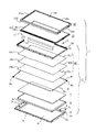
液晶表示装置1は、図1に示すように、バックライトユニット2、液晶表示パネル15及び前面枠18等の部材を備えている。これらの部材のうち液晶表示パネル15は、2枚の基板16a、16bを対向させて間に液晶層(図示省略)を設けて積層されたパネル16と、このパネル16に接続されたフレキシブル回路基板17とで構成され、この液晶表示パネル15は、バックライトユニット2が組み立てられた後に支持枠11上に載置され、前面枠18によりバックライトユニット2に固定される。なお2枚の基板16a、16bはその大きさが異なり、二辺をそろえて対向させており、そろえていない残りの二辺では基板16b上に走査線用のドライバ、映像信号線用のドライバがそれぞれ載置されている。
As shown in FIG. 1, the liquid crystal display device 1 includes members such as a
バックライトユニット2は、裏蓋ケース3、このケース3に収容される反射板6、導光板7、光学シート10及び線状光源8等と、これらの部品を収容し固定すると共に液晶表示パネル15を支持する支持枠11とで構成される。
The
これらの部品のうち裏蓋ケース3は、矩形状の底板3aと、この底板3aの外周縁から折曲された背低の側板3b〜3eとを有し、上方が開口し浅底の箱型ケースからなり、板金加工により形成される。
Among these components, the back cover case 3 has a rectangular bottom plate 3a and
側板3cには、線状光源8に接続されたリード線が導出される開口3c’が1個乃至複数個形成される。また、各側板3b〜3eのうち長辺の側板3dには、それぞれ複数個の係止部4が形成される。それぞれの係止部4は、図3に示すように、所定の幅及び長さを有する細溝、すなわちスリット4aと、このスリット4a上方の側板3dを凹ませた凹み部3d’とで構成される。側板3dを裏蓋ケース内側へ凹ませることにより、この凹み部3d’には後述の支持枠11に設けた線状突起14を係止する際にこの突起を側板表面から突出させないで設けることができる。
The
裏蓋ケース3の底板3a面には反射板6が敷設され、この反射板6は、反射材に例えば白色PETフィルムが使用される。また、導光板7は液晶表示パネル15とほぼ同じ大きさで、比較的厚い板厚で光を導光できる透明材料、例えばアクリル樹脂で形成される。この導光板7の外周囲には、線状光源8及び遮光テープ(図示省略)が配設されており、線状光源8には、ほぼL字状をなした蛍光ランプ8aが使用され、端部にそれぞれソケット8b、8bが装着され、導光板7の一角に当接させて配設される。また、遮光テープは遮光性のある材料で作製されたテープで、蛍光ランプ8aが配設されていない導光板7の他の一角に配設される。
A
光学シート10には、導光板7とほぼ同じ大きさを有する拡散シート10a、レンズシート10b、反射型偏光性シート10cが使用される。また、各シート10a〜10cの一端縁には、位置決め固定する突出片10a’〜10c’が形成される。
As the
支持枠11は、図2に示すように、内部に光学シート10を露出させる窓口11aを有し、周囲が4本の枠辺11b〜11eで囲まれた額縁状をなし、その外形は裏蓋ケース3の上部開口に嵌め込まれる大きさを有し合成樹脂材で形成される。
As shown in FIG. 2, the
前記合成樹脂材としては導電フィラが混入されたものを使用すると良い。導電フィラを混入した支持枠11を使用することにより、蛍光ランプ8aから出るノイズが外部へ放射されるのを効果的に遮蔽できる。ここで、合成樹脂材に混入する導電フィラの量を多くすれば、ノイズ対策としての効果がより高くなる反面、その分支持枠11の強度が低下し折れ曲がり易くなるという欠点がある。しかし後述する抜止手段を支持枠11に付設する本発明においては、支持枠11が折れ曲がり易くなったとしても、支持枠11が裏蓋ケース3から外れてしまうことを防止することができるので、ノイズ対策として、合成樹脂材に混入する導電フィラの量を増やすことも可能となる。
As the synthetic resin material, a material mixed with a conductive filler may be used. By using the
4本の枠辺11b〜11eのうち2本の枠片11c、11eは、蛍光ランプ8aを覆うため、また液晶パネル15を構成する基板16bの上に各種ドライバが載置さていることで表示エリア外の領域が広いため、その幅長が他の枠片11b、11dより幅広になっている。反対に枠片11b、11dは液晶パネル15の表示エリア外が狭く、狭額縁化のため幅挟になっている。また、各枠辺11b〜11eには、その表面の外周縁から、上方へ隆起させた囲い壁が形成される。この囲い壁を形成することにより、支持枠11上に液晶パネル15が載置されたときに液晶表示パネルの位置決めができるようになる。
Of the four
各枠辺11b〜11eのうち、枠辺11dには、その外壁に複数個(図2中では4個)の係止部121〜124が形成される。これらの係止部121〜124は、枠辺11dの外側壁に凹欠溝13で形成される。
Of
これらの凹欠溝13は、図2(b)に示すように、枠辺11dの長手方向に所定幅W0、枠辺11dの外側壁112dの表面からの深さW1、及び上面111dからの深さHを有し、溝の底部に平坦な底壁13aが形成された形状を有している。底壁13aは、外側壁112dの表面へ所定の長さW2突出した突出部13bが形成される
そして、支持枠11を裏蓋ケース3に取付ける際には、各凹欠溝13にケース側板3dの凹み部3d’が入り込み係止される。
As shown in FIG. 2B, these recessed
また、4個の係止部121〜124のうち、両端を除く係止部122、123には、凹欠溝13内の底壁面14先端縁のほぼ中央部に、所定の長さW3及び高さの線状突起14が形成される。この線状突起14は、上記凹み部3d’と係止され枠辺11dが外れないように抜止機能を果たすものである。なお、前記線状突起14は、線状に限定されず、任意の形状、例えば四角柱、三角柱、円柱でもよい。
Further, of the four locking
4本の枠辺11b〜11eのうち、枠片11dは、他の枠片11c、11eに比べて幅狭でかつ長いため、非常に曲り易くなっている。このため、各凹欠溝13にケース側板3dの凹み部3d’を入り込ませただけでは、枠片11dが曲がり易く、特に両端より中央部が曲がり易くなっている。そこで、4個の係止部121〜124のうち、両端を除く係止部122、123に突起14を設けることにより、効率よく抜止することができる。
Of the four
また、底壁13aの突出部13bの長さW2を裏蓋ケース3の板厚とほぼ同じ設定とすると、係合時にこの突出部13bがバックライトユニット2の外壁面から外へ突出することがなくなるので、他機器への組み込みの際に出っ張った部分がなくなり組込みが容易になる。
Also, the length W 2 of the projecting
なお、上記のW0、W1、H、W3等の長さは、例えば、7インチ型の液晶表示パネルでは、外形寸法が約165.40×92.20mmの支持枠を用いており、W0は約6.00mm、W1は約2.00mm、Hは約1.50mm、W3は約0.30mm、線状突起14の高さは、約0.15mmである。そしてこのように形成することで、十分な係止効果が得られた。
Note that the lengths of W 0 , W 1 , H, W 3 and the like described above are, for example, a 7-inch liquid crystal display panel using a support frame having an outer dimension of about 165.40 × 92.20 mm. W 0 is about 6.00 mm, W 1 is about 2.00 mm, H is about 1.50 mm, W 3 is about 0.30 mm, and the height of the
バックライトユニット1の組み立ては、先ず裏蓋ケース3の底部3aに反射板6を敷設し、この反射板6の上に導光板7を載置する。導光板7の外周囲にはL字状の蛍光ランプ8a及び遮光テープを配設し、これらの上に複数枚の光学シート10を載置する。蛍光ランプ8aの端部に取り付けられたソケット8b、8bに接続されたリード線8cは、開口3c’から外へ導出され、その他端にコネクタ9が取り付けられて外部電源への接続がなされる。
In assembling the backlight unit 1, first, the reflecting
裏蓋ケース3内に、反射板6、導光板7、光学シート10を収容した後に、支持枠11を裏蓋ケース3に嵌め込み、導光板7、光学シート10を固定して、バックライトユニット2を組立てる(図3(a))。支持枠11を裏蓋ケース3に嵌め込む際には、図2(b)、図3(b)に示すように、支持枠11の突出部13bが裏蓋ケース3のスリット4aに挿入され、線状突起14がケース側板3dの凹み部3d’に係止され抜止めとなる。
After the
次いで、支持枠11上に液晶パネル15を載置して、その上を前面枠18で覆い、この前面枠18を裏蓋ケース3に固定して液晶表示装置を完成させる。
Next, the
したがって、このバックライトユニット2を使用することにより、支持枠11が裏蓋ケース3から外れることがなくなるので、次工程においてバックライトユニット2に液晶パネル15を組み込む際に、支持枠11の外れ検査及び補修等が不要になり、装置の組立て工数の低減を図ることができる。
Therefore, since the
例えば、このバックライトユニットが部品メーカーで組立てられた後、装置メーカーへ搬送される途中、或いはその後の組み立てライン等において振動、衝撃、或いは扱い方によって支持枠が裏蓋ケースから外れてしまうことがなくなるので、支持枠の外れ検査及び補修等が不要になり、組立て工数が低減し液晶表示装置の生産性を上げることができる。 For example, after the backlight unit is assembled by a parts manufacturer, the support frame may come off from the back cover case due to vibration, impact, or handling in the middle of being transported to the device manufacturer or in the subsequent assembly line. As a result, there is no need for inspection and repair of the support frame, the number of assembling steps can be reduced, and the productivity of the liquid crystal display device can be increased.
なお、バックライトの光源として線状光源である蛍光ランプを用いて説明したが、光源としては蛍光ランプのような線状光源に限定されるものではなく、LEDのような点状光源を用いたものや、面状光源を用いたものでもよく、何れにしろ光源の形状に限定はなく、光源からの光がバックライトから出射する際に均一となって液晶パネルを照らすこととなればよい。 In addition, although it demonstrated using the fluorescent lamp which is a linear light source as a light source of a backlight, it is not limited to a linear light source like a fluorescent lamp as a light source, The point light source like LED was used. In any case, there is no limitation on the shape of the light source, and it is sufficient that the light from the light source becomes uniform and illuminates the liquid crystal panel when emitted from the backlight.
1 液晶表示装置
2 バックライトユニット
3 裏蓋ケース(箱型ケース)
4 係止部
6 反射板
7 導光板
8 線状光源
10 光学シート
11 支持枠
13 凹欠溝
14 線状突起(抜止手段)
15 液晶表示パネル
18 前面枠
1
4 Locking
15
Claims (6)
前記箱型ケースの側壁内側には第1係止部、前記箱型ケースの上方開口内に嵌め込まれる前記支持枠の枠側壁の外側表面には第2係止部をそれぞれ設け、
前記第2係止部は、前記支持枠の上方が開口した所定の深さを有する凹欠溝からなり、この凹欠溝の底壁面に前記抜止手段が設けられ、
前記第1、第2係止部が係合されたときに前記抜止手段が前記第1係止部に係止され抜止めされることを特徴とするバックライトユニット。 A box-shaped case having a side wall and an upper opening, and a frame-shaped support for fixing the optical member by accommodating an optical member such as a light source and an optical sheet inside the box-shaped case and fitting the optical member in the opening In a backlight unit with a frame,
A first locking portion is provided on the inside of the side wall of the box-type case, and a second locking portion is provided on the outer surface of the frame side wall of the support frame fitted into the upper opening of the box-type case,
The second locking portion comprises a recessed groove having a predetermined depth opened above the support frame, and the retaining means is provided on the bottom wall surface of the recessed groove,
The backlight unit, wherein when the first and second engaging portions are engaged, the retaining means is retained and retained by the first retaining portion.
Priority Applications (5)
| Application Number | Priority Date | Filing Date | Title |
|---|---|---|---|
| JP2004318076A JP4631396B2 (en) | 2004-11-01 | 2004-11-01 | Backlight unit and liquid crystal display device using the same |
| PCT/JP2005/019577 WO2006049040A1 (en) | 2004-11-01 | 2005-10-25 | Backlight unit and liquid crystal display employing it |
| US11/718,294 US7659949B2 (en) | 2004-11-01 | 2005-10-25 | Backlight unit and liquid crystal display employing the same |
| KR1020077009937A KR100878388B1 (en) | 2004-11-01 | 2005-10-25 | Backlight unit and liquid crystal display employing it |
| TW094138033A TW200619782A (en) | 2004-11-01 | 2005-10-31 | Backlight unit and liquid crystal display device using the same |
Applications Claiming Priority (1)
| Application Number | Priority Date | Filing Date | Title |
|---|---|---|---|
| JP2004318076A JP4631396B2 (en) | 2004-11-01 | 2004-11-01 | Backlight unit and liquid crystal display device using the same |
Publications (2)
| Publication Number | Publication Date |
|---|---|
| JP2006128036A JP2006128036A (en) | 2006-05-18 |
| JP4631396B2 true JP4631396B2 (en) | 2011-02-16 |
Family
ID=36319054
Family Applications (1)
| Application Number | Title | Priority Date | Filing Date |
|---|---|---|---|
| JP2004318076A Active JP4631396B2 (en) | 2004-11-01 | 2004-11-01 | Backlight unit and liquid crystal display device using the same |
Country Status (5)
| Country | Link |
|---|---|
| US (1) | US7659949B2 (en) |
| JP (1) | JP4631396B2 (en) |
| KR (1) | KR100878388B1 (en) |
| TW (1) | TW200619782A (en) |
| WO (1) | WO2006049040A1 (en) |
Families Citing this family (16)
| Publication number | Priority date | Publication date | Assignee | Title |
|---|---|---|---|---|
| TW200815848A (en) * | 2006-09-22 | 2008-04-01 | Innolux Display Corp | Backlight module and liquid crystal display device using the same |
| KR101262179B1 (en) * | 2007-01-19 | 2013-05-14 | 삼성디스플레이 주식회사 | Display device and case for the same |
| DE202007002131U1 (en) * | 2007-02-13 | 2007-04-19 | Patent-Treuhand-Gesellschaft für elektrische Glühlampen mbH | Lighting system for background illumination of liquid crystal displays comprises a frame having an upper part and a lower part joined together using a detachable connecting unit and a flat lamp arranged between the upper part and lower part |
| WO2009008617A2 (en) * | 2007-07-06 | 2009-01-15 | Lg Innotek Co., Ltd | Display device |
| KR100901616B1 (en) * | 2007-07-06 | 2009-06-08 | 엘지이노텍 주식회사 | Receiving device and display device having the receiving device |
| JP5007638B2 (en) * | 2007-09-26 | 2012-08-22 | 富士通株式会社 | Electronics |
| JP5369948B2 (en) * | 2009-07-10 | 2013-12-18 | カシオ計算機株式会社 | Surface light source and liquid crystal display device |
| TWI410715B (en) * | 2009-12-18 | 2013-10-01 | Au Optronics Corp | Backlight module and plastic frame structure thereof |
| KR101278904B1 (en) | 2011-12-27 | 2013-06-26 | (주)코텍 | Curved display |
| TWI502824B (en) * | 2012-12-04 | 2015-10-01 | Wistron Corp | Fixing mechanism and related electronic device |
| JP6096615B2 (en) * | 2013-07-11 | 2017-03-15 | ミネベアミツミ株式会社 | Surface lighting device |
| US10302846B2 (en) | 2015-02-02 | 2019-05-28 | Sharp Kabushiki Kaisha | Display device |
| WO2019028688A1 (en) * | 2017-08-09 | 2019-02-14 | 瑞仪(广州)光电子器件有限公司 | Frame assembly and display device |
| JP2019082535A (en) * | 2017-10-30 | 2019-05-30 | シャープ株式会社 | Display device |
| KR102253915B1 (en) * | 2019-09-18 | 2021-05-20 | 엘지전자 주식회사 | Display device |
| TWI724874B (en) * | 2020-04-21 | 2021-04-11 | 香港商冠捷投資有限公司 | Display device and manufacturing method thereof |
Citations (2)
| Publication number | Priority date | Publication date | Assignee | Title |
|---|---|---|---|---|
| JPH04291319A (en) * | 1991-03-20 | 1992-10-15 | Hitachi Ltd | Small-sized liquid crystal module |
| JPH1152379A (en) * | 1997-06-06 | 1999-02-26 | Toshiba Corp | Surface light source device and plane display device using the same |
Family Cites Families (6)
| Publication number | Priority date | Publication date | Assignee | Title |
|---|---|---|---|---|
| JPH07199180A (en) * | 1994-01-07 | 1995-08-04 | Hitachi Ltd | Liquid crystal display device |
| JP2001013889A (en) * | 1999-06-29 | 2001-01-19 | Toshiba Corp | Plane display device |
| KR100367012B1 (en) * | 2000-08-21 | 2003-01-09 | 엘지.필립스 엘시디 주식회사 | Liquid Crystal Display |
| JP2003092020A (en) | 2001-09-17 | 2003-03-28 | Seiko Instruments Inc | Display device with backlight |
| JP2004165031A (en) | 2002-11-14 | 2004-06-10 | Toyota Industries Corp | Flat light source device |
| JP4122964B2 (en) * | 2002-12-20 | 2008-07-23 | 豊田合成株式会社 | License plate lighting device |
-
2004
- 2004-11-01 JP JP2004318076A patent/JP4631396B2/en active Active
-
2005
- 2005-10-25 US US11/718,294 patent/US7659949B2/en active Active
- 2005-10-25 KR KR1020077009937A patent/KR100878388B1/en active IP Right Grant
- 2005-10-25 WO PCT/JP2005/019577 patent/WO2006049040A1/en active Application Filing
- 2005-10-31 TW TW094138033A patent/TW200619782A/en unknown
Patent Citations (2)
| Publication number | Priority date | Publication date | Assignee | Title |
|---|---|---|---|---|
| JPH04291319A (en) * | 1991-03-20 | 1992-10-15 | Hitachi Ltd | Small-sized liquid crystal module |
| JPH1152379A (en) * | 1997-06-06 | 1999-02-26 | Toshiba Corp | Surface light source device and plane display device using the same |
Also Published As
| Publication number | Publication date |
|---|---|
| KR100878388B1 (en) | 2009-01-13 |
| KR20070073848A (en) | 2007-07-10 |
| TWI305286B (en) | 2009-01-11 |
| WO2006049040A1 (en) | 2006-05-11 |
| JP2006128036A (en) | 2006-05-18 |
| US7659949B2 (en) | 2010-02-09 |
| TW200619782A (en) | 2006-06-16 |
| US20080088762A1 (en) | 2008-04-17 |
Similar Documents
| Publication | Publication Date | Title |
|---|---|---|
| TWI305286B (en) | ||
| CN102080785B (en) | Backlight assembly | |
| KR20090110068A (en) | Display apparatus | |
| KR20090060748A (en) | Display apparatus, upper container, and method of assembling the display apparatus | |
| US20100147582A1 (en) | Display panel and display device including the same | |
| JP2005327700A (en) | Backlight unit | |
| JP2005078917A (en) | Backlight device | |
| KR101020923B1 (en) | Optical assembly, backlight unit having the same, and display apparatus thereof | |
| JP2005078832A (en) | Backlight device | |
| WO2013191051A1 (en) | Display, and television receiver | |
| JP5050876B2 (en) | LCD module | |
| JP4605401B2 (en) | Backlight device | |
| JP4626621B2 (en) | Backlight device | |
| JP4650448B2 (en) | Backlight device | |
| JP4650446B2 (en) | Backlight device | |
| JP2008129474A (en) | Display device | |
| JP2007053094A (en) | Molder frame, and backlight assembly and display device equipped with molder frame | |
| JP2008046266A (en) | Liquid crystal display and its frame | |
| JP2005284106A (en) | Back light unit, liquid crystal display device, and frame member | |
| JP2005078873A (en) | Backlight device | |
| KR20070073113A (en) | Bottom chassis with optical sheets fixture and liquid crystal display using the same | |
| JP2008065211A (en) | Liquid crystal display | |
| KR102102909B1 (en) | Backlight unit | |
| KR101700163B1 (en) | Curved display and assembling method thereof | |
| JP2001273807A (en) | Back light apparatus and display having the same |
Legal Events
| Date | Code | Title | Description |
|---|---|---|---|
| A711 | Notification of change in applicant |
Free format text: JAPANESE INTERMEDIATE CODE: A711 Effective date: 20070228 |
|
| A621 | Written request for application examination |
Free format text: JAPANESE INTERMEDIATE CODE: A621 Effective date: 20070727 |
|
| A131 | Notification of reasons for refusal |
Free format text: JAPANESE INTERMEDIATE CODE: A131 Effective date: 20100511 |
|
| A521 | Request for written amendment filed |
Free format text: JAPANESE INTERMEDIATE CODE: A523 Effective date: 20100707 |
|
| TRDD | Decision of grant or rejection written | ||
| A01 | Written decision to grant a patent or to grant a registration (utility model) |
Free format text: JAPANESE INTERMEDIATE CODE: A01 Effective date: 20101019 |
|
| A01 | Written decision to grant a patent or to grant a registration (utility model) |
Free format text: JAPANESE INTERMEDIATE CODE: A01 |
|
| A61 | First payment of annual fees (during grant procedure) |
Free format text: JAPANESE INTERMEDIATE CODE: A61 Effective date: 20101101 |
|
| R150 | Certificate of patent or registration of utility model |
Ref document number: 4631396 Country of ref document: JP Free format text: JAPANESE INTERMEDIATE CODE: R150 Free format text: JAPANESE INTERMEDIATE CODE: R150 |
|
| FPAY | Renewal fee payment (event date is renewal date of database) |
Free format text: PAYMENT UNTIL: 20131126 Year of fee payment: 3 |
|
| S111 | Request for change of ownership or part of ownership |
Free format text: JAPANESE INTERMEDIATE CODE: R313113 |
|
| FPAY | Renewal fee payment (event date is renewal date of database) |
Free format text: PAYMENT UNTIL: 20131126 Year of fee payment: 3 |
|
| R350 | Written notification of registration of transfer |
Free format text: JAPANESE INTERMEDIATE CODE: R350 |
|
| FPAY | Renewal fee payment (event date is renewal date of database) |
Free format text: PAYMENT UNTIL: 20131126 Year of fee payment: 3 |
|
| S111 | Request for change of ownership or part of ownership |
Free format text: JAPANESE INTERMEDIATE CODE: R313113 |
|
| FPAY | Renewal fee payment (event date is renewal date of database) |
Free format text: PAYMENT UNTIL: 20131126 Year of fee payment: 3 |
|
| R350 | Written notification of registration of transfer |
Free format text: JAPANESE INTERMEDIATE CODE: R350 |
|
| R250 | Receipt of annual fees |
Free format text: JAPANESE INTERMEDIATE CODE: R250 |
|
| R250 | Receipt of annual fees |
Free format text: JAPANESE INTERMEDIATE CODE: R250 |
|
| R250 | Receipt of annual fees |
Free format text: JAPANESE INTERMEDIATE CODE: R250 |
|
| R250 | Receipt of annual fees |
Free format text: JAPANESE INTERMEDIATE CODE: R250 |
|
| R250 | Receipt of annual fees |
Free format text: JAPANESE INTERMEDIATE CODE: R250 |
|
| R250 | Receipt of annual fees |
Free format text: JAPANESE INTERMEDIATE CODE: R250 |
|
| R250 | Receipt of annual fees |
Free format text: JAPANESE INTERMEDIATE CODE: R250 |
|
| R250 | Receipt of annual fees |
Free format text: JAPANESE INTERMEDIATE CODE: R250 |
|
| S111 | Request for change of ownership or part of ownership |
Free format text: JAPANESE INTERMEDIATE CODE: R313111 |
|
| R350 | Written notification of registration of transfer |
Free format text: JAPANESE INTERMEDIATE CODE: R350 |
|
| R250 | Receipt of annual fees |
Free format text: JAPANESE INTERMEDIATE CODE: R250 |
|
| R250 | Receipt of annual fees |
Free format text: JAPANESE INTERMEDIATE CODE: R250 |