JP4627396B2 - Attaching the component elements to the filtering material available in the respiratory mask - Google Patents
Attaching the component elements to the filtering material available in the respiratory mask Download PDFInfo
- Publication number
- JP4627396B2 JP4627396B2 JP2001531461A JP2001531461A JP4627396B2 JP 4627396 B2 JP4627396 B2 JP 4627396B2 JP 2001531461 A JP2001531461 A JP 2001531461A JP 2001531461 A JP2001531461 A JP 2001531461A JP 4627396 B2 JP4627396 B2 JP 4627396B2
- Authority
- JP
- Japan
- Prior art keywords
- extension member
- exhalation valve
- mask
- mask body
- base
- Prior art date
- Legal status (The legal status is an assumption and is not a legal conclusion. Google has not performed a legal analysis and makes no representation as to the accuracy of the status listed.)
- Expired - Fee Related
Links
Images


Classifications
-
- A—HUMAN NECESSITIES
- A62—LIFE-SAVING; FIRE-FIGHTING
- A62B—DEVICES, APPARATUS OR METHODS FOR LIFE-SAVING
- A62B23/00—Filters for breathing-protection purposes
- A62B23/02—Filters for breathing-protection purposes for respirators
- A62B23/025—Filters for breathing-protection purposes for respirators the filter having substantially the shape of a mask
-
- A—HUMAN NECESSITIES
- A62—LIFE-SAVING; FIRE-FIGHTING
- A62B—DEVICES, APPARATUS OR METHODS FOR LIFE-SAVING
- A62B18/00—Breathing masks or helmets, e.g. affording protection against chemical agents or for use at high altitudes or incorporating a pump or compressor for reducing the inhalation effort
- A62B18/08—Component parts for gas-masks or gas-helmets, e.g. windows, straps, speech transmitters, signal-devices
- A62B18/10—Valves
-
- A—HUMAN NECESSITIES
- A62—LIFE-SAVING; FIRE-FIGHTING
- A62B—DEVICES, APPARATUS OR METHODS FOR LIFE-SAVING
- A62B23/00—Filters for breathing-protection purposes
- A62B23/02—Filters for breathing-protection purposes for respirators
-
- B—PERFORMING OPERATIONS; TRANSPORTING
- B01—PHYSICAL OR CHEMICAL PROCESSES OR APPARATUS IN GENERAL
- B01D—SEPARATION
- B01D46/00—Filters or filtering processes specially modified for separating dispersed particles from gases or vapours
- B01D46/0001—Making filtering elements
-
- B—PERFORMING OPERATIONS; TRANSPORTING
- B01—PHYSICAL OR CHEMICAL PROCESSES OR APPARATUS IN GENERAL
- B01D—SEPARATION
- B01D46/00—Filters or filtering processes specially modified for separating dispersed particles from gases or vapours
- B01D46/0002—Casings; Housings; Frame constructions
- B01D46/0005—Mounting of filtering elements within casings, housings or frames
-
- B—PERFORMING OPERATIONS; TRANSPORTING
- B01—PHYSICAL OR CHEMICAL PROCESSES OR APPARATUS IN GENERAL
- B01D—SEPARATION
- B01D46/00—Filters or filtering processes specially modified for separating dispersed particles from gases or vapours
- B01D46/10—Particle separators, e.g. dust precipitators, using filter plates, sheets or pads having plane surfaces
- B01D46/12—Particle separators, e.g. dust precipitators, using filter plates, sheets or pads having plane surfaces in multiple arrangements
-
- B—PERFORMING OPERATIONS; TRANSPORTING
- B01—PHYSICAL OR CHEMICAL PROCESSES OR APPARATUS IN GENERAL
- B01D—SEPARATION
- B01D46/00—Filters or filtering processes specially modified for separating dispersed particles from gases or vapours
- B01D46/42—Auxiliary equipment or operation thereof
- B01D46/4272—Special valve constructions adapted to filters or filter elements
-
- B—PERFORMING OPERATIONS; TRANSPORTING
- B01—PHYSICAL OR CHEMICAL PROCESSES OR APPARATUS IN GENERAL
- B01D—SEPARATION
- B01D53/00—Separation of gases or vapours; Recovering vapours of volatile solvents from gases; Chemical or biological purification of waste gases, e.g. engine exhaust gases, smoke, fumes, flue gases, aerosols
- B01D53/02—Separation of gases or vapours; Recovering vapours of volatile solvents from gases; Chemical or biological purification of waste gases, e.g. engine exhaust gases, smoke, fumes, flue gases, aerosols by adsorption, e.g. preparative gas chromatography
- B01D53/04—Separation of gases or vapours; Recovering vapours of volatile solvents from gases; Chemical or biological purification of waste gases, e.g. engine exhaust gases, smoke, fumes, flue gases, aerosols by adsorption, e.g. preparative gas chromatography with stationary adsorbents
- B01D53/0407—Constructional details of adsorbing systems
- B01D53/0415—Beds in cartridges
-
- A—HUMAN NECESSITIES
- A62—LIFE-SAVING; FIRE-FIGHTING
- A62B—DEVICES, APPARATUS OR METHODS FOR LIFE-SAVING
- A62B9/00—Component parts for respiratory or breathing apparatus
- A62B9/04—Couplings; Supporting frames
-
- B—PERFORMING OPERATIONS; TRANSPORTING
- B01—PHYSICAL OR CHEMICAL PROCESSES OR APPARATUS IN GENERAL
- B01D—SEPARATION
- B01D2259/00—Type of treatment
- B01D2259/40—Further details for adsorption processes and devices
- B01D2259/414—Further details for adsorption processes and devices using different types of adsorbents
- B01D2259/4141—Further details for adsorption processes and devices using different types of adsorbents within a single bed
- B01D2259/4145—Further details for adsorption processes and devices using different types of adsorbents within a single bed arranged in series
- B01D2259/4148—Multiple layers positioned apart from each other
-
- B—PERFORMING OPERATIONS; TRANSPORTING
- B01—PHYSICAL OR CHEMICAL PROCESSES OR APPARATUS IN GENERAL
- B01D—SEPARATION
- B01D2259/00—Type of treatment
- B01D2259/45—Gas separation or purification devices adapted for specific applications
- B01D2259/4541—Gas separation or purification devices adapted for specific applications for portable use, e.g. gas masks
-
- B—PERFORMING OPERATIONS; TRANSPORTING
- B01—PHYSICAL OR CHEMICAL PROCESSES OR APPARATUS IN GENERAL
- B01D—SEPARATION
- B01D2265/00—Casings, housings or mounting for filters specially adapted for separating dispersed particles from gases or vapours
- B01D2265/02—Non-permanent measures for connecting different parts of the filter
- B01D2265/021—Anti-rotational means
-
- B—PERFORMING OPERATIONS; TRANSPORTING
- B01—PHYSICAL OR CHEMICAL PROCESSES OR APPARATUS IN GENERAL
- B01D—SEPARATION
- B01D2265/00—Casings, housings or mounting for filters specially adapted for separating dispersed particles from gases or vapours
- B01D2265/04—Permanent measures for connecting different parts of the filter, e.g. welding, glueing or moulding
-
- B—PERFORMING OPERATIONS; TRANSPORTING
- B01—PHYSICAL OR CHEMICAL PROCESSES OR APPARATUS IN GENERAL
- B01D—SEPARATION
- B01D2275/00—Filter media structures for filters specially adapted for separating dispersed particles from gases or vapours
- B01D2275/10—Multiple layers
-
- B—PERFORMING OPERATIONS; TRANSPORTING
- B01—PHYSICAL OR CHEMICAL PROCESSES OR APPARATUS IN GENERAL
- B01D—SEPARATION
- B01D2279/00—Filters adapted for separating dispersed particles from gases or vapours specially modified for specific uses
- B01D2279/55—Filters adapted for separating dispersed particles from gases or vapours specially modified for specific uses for cleaning appliances, e.g. suction cleaners
Abstract
Description
【0001】
技術分野
本発明は、呼吸マスクの作製で使用するために特に適切なタイプのこのような材料を含む濾過材料に、1つ以上の部品要素を取り付けるための方法に関する。特に、本発明は、1つ以上の部品を濾過材料に取り付ける方法に関し、この場合好ましい方法は、高速製造システムの部分としての自動生産に適切な方法である。本発明は、本発明の方法に従って共に取り付けられる部品と濾過材料との組合せに関する。呼吸マスクに取り付けられる典型的な部品は、例えばバルブ、ヘッドバンド等を含む。
【0002】
発明の背景
濾過材料は、任意の数の異なるタイプのフィルタ内に組み込むことが可能であり、および/または濾過装置内に形成するか、さもなければ構成することが可能である。いずれにしろ、濾過材料への他の要素の組込みを容易にするために、あるいはフィルタ材料を濾過装置として構成するとき、部品要素を濾過材料に取り付けることが望ましいかもしれない。濾過材料それ自体には、典型的に、媒体を通した流体の流れを許容するが、フィルタ媒体を通した粒子状物質等の通過を制限する媒体内のオリフィスまたは通路を画定できる媒体が含まれる。さもなければ、このような媒体は、微粒子除去(すなわち吸引または化学反応による)の代わりにまたはそれに追加して、流体が濾過媒体を通過するときに流体から流体の任意の構成成分を除去するように設計し得る。
【0003】
本発明は、特に、空気中の汚染物質および/または不快または不愉快なガスからユーザの呼吸器系を保護するための多種多様の用途において利用される呼吸マスクの生産のために開発された。さらに、治療者は、治療者へのまたは治療者からの有害な微生物の拡散を防止するためにこのような呼吸マスクを利用する。
【0004】
種々の形態の呼吸マスクが商業的に入手可能であり、それらのいくつかは、それらが比較的短期間使用するように意図されるので「使い捨て可能」として分類される。他の非使い捨ての呼吸マスクは、マスクそれら自体は再利用可能であるが、交換可能なフィルタを含むことが可能である。使い捨て可能なマスクは、典型的に、空気濾過材料から主に形成されるマスク本体を有し、またマスク本体は、少なくとも人の鼻と口に合うように賦形されるかまたは構成可能である。使い捨てでないマスク用の交換フィルタは、典型的に、フィルタと再利用可能なマスクとが接続可能である構造部品と共に空気濾過材料の層を含む。
【0005】
使い捨て呼吸マスクは、複数のカテゴリの1つに一般的に分類でき、それらのいくつかは次のように説明される。1)時々折り畳まれるかプリーツされ、また人の鼻と口に比較的平らに合うように寸法決めされる平らな可撓性マスク、2)平らな状態に折り畳み、またマスクが人の鼻と口に合うことができるカップ状の使用可能状態に広げることができる折り畳み可能なマスク、3)それらの使用可能な状態に予め形成される成形マスク。これらの内、平らに折り畳まれるマスクのいずれのタイプも平らに束ねることができ、また使用に対応するために適切な縫い目、プリーツおよび/または折り畳みを設けることが可能である。カップ状の状態に広げることができる折り畳み可能なタイプのマスクは、概してカップ形状にマスクを開くことを可能にする縫い目、プリーツおよび/または折り目によって画定されるパネルによって通常形成される。他方で、成形マスクは、所望の顔適合形状に予め形成され、使用中にその形状を一般的に保持する。平らに折り畳まれたまたは成形されたマスクが使用されるとき、マスク本体は、着用者の少なくとも鼻と口の周囲に少なくともある程度の呼吸ゾーンを形成する。着用者が吸入するとき、空気が空気濾過材料を通して呼吸ゾーンに引き込まれる。
【0006】
使い捨て呼吸マスクは、一般的に、少なくとも1つの取り付けられる部品を組み込み、この部品は、濾過材料層または濾過材料層を有する複合材料にまたはそれを通して取り付けられる。例えば、このようなマスクのほとんどすべては、マスクをユーザの頭に固定できるヘッドバンド、ひもまたは他の手段を含む。さらに、このようなマスクは、バルブ、鼻クリップおよび顔シールドを含む他の取り付け部品を組み込むことも公知である。
【0007】
このような部品を取り付けるためにしばしば使用されるある方法は、例えば米国特許第5,325,893号に記述されているような熱溶接または超音波溶接の利用をベースとする。これらの方法は、部品が濾過材料によって有効にシールされるように、このような部品を取り付けることができるという点で有利である。すなわち、部品周囲全体にわたって溶接を行うことができるので、おそらくは繊維質材料である濾過材料をそれ自体と部品とに熱可塑性に溶接することができる。かくして、濾過材料の濾過効果が取付け界面で損なわれないように、部品を濾過材料に対しシールすることができる。しかし、溶接技術は、超音波または熱処理を行うために比較的複雑な装置の用意を必要とし、また特に繊維質材料が部品と接続される場合、優れた取付け成果を確かにするために十分な制御システムを必要とする点において、一般的に他のものよりも高価で、複雑である。
【0008】
代わりに、ある部品および他の形態の呼吸器のために、接着結合の利用が知られている。接着結合の利点は、溶接と同様に、効果的な取付けをより容易に行うことができることである。すなわち、接着剤が濾過材料と部品の両方に適合する限り、部品の周囲全体にわたって接着剤を塗布して優れた取付け部を形成することができる。しかし、この取付け部によって形成されるシールは、接着剤が塗布される箇所においてのみ強化される。すなわち、接着剤で外層(濾過材料または他のものであり得る)を取り付けて部品に対しシールし得るが、他の層は外層または部品と互いにシールされないことがあり得る。したがって、優れたシール(すなわち、例えばより大きな粒子が通過するのを許容しないシールはフィルタの機能である)が損なわれる可能性がある。いずれにしろ、このような接着剤付着技術は、接着剤の追加出費を必要とし、さらに接着剤の塗布を分配かつ制御する手段の用意を必要とする。このことはコストと複雑さを増す。
【0009】
他の状態では、ステープルのような締結具または他の締付構造体の使用を含む機械的締付技術も知られている。このような機械的なシステムは、熱および/または超音波発生器および制御装置、あるいは接着剤分配および塗布装置および制御装置のような複雑な接合装置を必要としない点において、一般的な利点を有する。しかし、他方、機械的締付システムそれ自体は、その代わりに複雑な整列および制御機構を必要とする可能性がある。機械的取付け技術の例は、米国特許第5,374,458号と第5,080,094号、および公開された国際出願WO96/11594と96/28217に開示されている。機械的締結具または締付システムを利用する場合の最大の関心は、効果的なシール、すなわち、相当量の汚染物質の通過を許容しないシールの形成であり、当該汚染物質は、さもなければ部品が取り付けられた濾過材料によって除去されるように意図されるこの問題は、マスク上のどこに(例えば、鼻の側面から離れた点と異なりユーザの鼻の真正面のような場所)部品が取り付けられるかに応じて変わり得る。さらに、ある機械的締付方法は、追加の固定部品の用意を必要とし得るだけでなく、追加の整列ステップおよびファスナまたは締付操作ステップを必要とし得る。
【0010】
これらの取付け方法は、部品を流体濾過材料に固定することが必要な場合に、例えば真空掃除機ごみ袋のようなエアフィルタおよびオイルフィルタの製造時に、他の分野においても使用されている。流体濾過の分野以外に利用される機械的締付技術の例は、米国特許第4,909,434号、第5,125,886号および第5,199,635号に開示され、この特許では、注出口を液体容器に固定するために機械的締付が利用される(ある場合にはヒートシールと組み合わせて)。
【0011】
本発明の要旨
本発明は、部品を濾過材料に取り付けるために、濾過材料と部品との間の効果的なシールを形成するために適切な機械的取付け技術を提供することによって、従来技術の不完全さと欠点を克服する。さらに、本発明は、インライン生産システムの部分として実施でき、また高速生産ラインで特に利用できるこのような技術を含む。
【0012】
さらに、本発明の方法は、基部側を有する濾過材料に取り付けられる部品と、濾過材料の中を延長部材を通過させることによって、また濾過材料と接触する延長部材の少なくともある部分または延長部材の基部側とは別の材料側を含む複合材料部分を有することによって、部品を濾過材料に締め付ける際に使用される延長部材とを利用する。延長部材は、材料を通して設けられると共に延長部材が部品の周囲に完全に効果的なシールを形成するように通過する開口部周囲全体にわたって材料の他の側と接触していることが好ましい。
【0013】
本発明の方法は、材料の開口部を通して部品の延長部材を挿入し、その後部品と材料との間に効果的なシールを形成するように、延長部材の変形を引き起こして材料と十分に接触した表面を延長部材が有するようにさせる変形ステップを実行するステップを含む。材料は、変形ステップの間に、特に濾過材料が2層以上を含む複合ウェブである場合(複数の層が互いにシールするように)、効果的なシールが強化されるように変形面と部品基部との間に少なくとも部分的に圧縮されることが好ましい。
【0014】
部品を濾過材料に取り付けるこのような技術と方法は、最小限のシステムの複雑さにより、濾過材料との効果的なシールを提供するために効果的な機械的締付装置によって、部品をこのような濾過材料に比較的容易に取り付けることができる点において、特に有利である。本発明の方法は、部品を濾過材料に位置決めするのと同時に延長部材を位置決めするので、部品に追加して、取り扱いかつ位置決めしなければならない追加部品を用意する必要がない。好ましくは、延長部材は部品と一体的に作製される。変形ステップは、部品の延長部分が作製される材料に応じて、熱を加えることなしに冷間形成工程として、あるいは熱または加熱形成工程の部分として行うことができる。本発明の方法は、比較的高速で実施可能なインライン生産システムの部分として利用するために特に適応できる。
【0015】
より具体的には、本発明は、部品、例えば呼吸マスクの部分を形成する空気濾過材料に呼気弁を取り付ける代替的方法を提供することに関する。
【0016】
本発明の前述の利点は、部品と濾過材料を含むウェブとを用意することによって達成でき、この場合部品は、第1および第2の主面と開口とを含むウェブに取り付けられ、および部品は材料の第1の主面に対して配置される基部と、基部から開口を通して延在する延長部材とを具備し、また基部に向かって折り返される延長部材の変形部分を有し、基部の少なくとも一部分は、材料と液密関係に部品を機械的に締め付けるように流体濾過材料の第2の主面に対して配置される。濾過材料は、部品とウェブとの取り付け状態において少なくとも幾分圧縮されることが好ましい。
【0017】
本発明はまた、上述したようにウェブと部品との組合せを作製する方法を提供し、この場合、本方法は、第1および第2の主面と開口とを有する、濾過材料層を含むウェブを用意するステップと、基部とこの基部から延在する変形可能な延長部材とを具備する部品を用意するステップと、開口を通して延在する延長部材を有するウェブの第1の主面に対して部品基部を位置決めするステップと、延長部材の少なくとも一部分がウェブの第2の主面に当接して、材料と液密関係に部品を締め付けるように延長部材を基部に向かって変形して戻すステップと、を含む。
【0018】
好適な実施形態の詳細な説明
複数の図面にわたって同様の構成要素に同様の参照番号が付された図面を参照すると、任意の長さの濾過材料12の一部に部品10を取り付ける方法が図1〜図5に示されている。濾過材料12は、公知の任意の濾過材料を表すために示され、その目的は、1つのみの濾過層または1つ以上の濾過層が含まれる濾過材料を含む濾過材料を流体が通過するとき、濾過すべき流体の任意の成分部分を流体から除去することである。さらに、図示した濾過材料層12は、濾過材料(1つ以上の濾過層)に他の構造体を組み込むおよび/または濾過層以外の付加層と組み合わせた複合ウェブを含むことが意図される。部品10は、濾過材料12に取り付けるために望ましい任意の部品であることが可能であり、また典型的に、任意の特定の用途に応じて濾過材料にある特徴を加える部品を具備する。例えば、本発明が特に取り組む呼吸マスクの場合、このような部品10は、呼気弁、ハーネス、アイシールド、ヘッドバンド等、または呼吸マスクを作製する際に使用するために適切な濾過材料12に固定されるこのような部品の任意の部分を含み得る。他の濾過材料12は、任意の数の他の用途のために、このような他の用途に適切であり得る他の部品10との組合わせが意図され、他の用途のいくつかについては以下に説明する。本発明は、このような部品10を濾過材料12に取り付ける方法、および濾過材料12と部品10との結果として得られる組合せに関する。
【0019】
図1に示したように、部品10は、濾過材料12を通して設けられる開口部14を通過するように位置決めされる。図2に示したように、開口部14の形状は円形であるが、開口部14の形状は任意の形状であり得ることが理解される。好ましくは、開口部14は、特に延長部材16が濾過材料12の開口部14を直接通過する箇所で、部品10の変形可能な延長部材16の形状と一致するように賦形される。図1にも示されているように、開口部14は、部品10の延長部材16の寸法よりもわずかに大きく寸法決めし得る。
【0020】
部品10はまた、部品10の延長部材16が開口部14内に位置決めされるときに濾過材料12の開口部14を少なくとも部分的に囲む、好ましくは完全に囲む基部18を含む。かくして、基部18は、開口部14にちょうど隣接した濾過材料12の第1の主面22の一部分に寄り掛かるための表面部分20を提供する。濾過材料12の第2の主面24はまた、部品10が以下に説明する取付け工程に従って修正されるときに部品の延長部材16の少なくとも一部分に接触するために使用される開口部14を囲む前記濾過部材の一部分を含む。部品10はまた、図示したように中央開口部26と、部品への追加部品の装着を容易にするための基部18からまた変形可能な延長部材16から離れて延在する表面特徴部28とを具備する。すなわち、表面特徴部28は、例えばさらなる部品上に設けられる接続システムの他の部分と協働する接続システムの部分として用意される。図示した例では、開口部26は、部品10によって濾過材料12に加えられることが望まれる機能的特徴の部分として、部品10を通した流体の制御通路を許容するために設けられる。開口部26および表面特徴部28は、任意の特定の用途に基づく部品10の特定の用途および機能的特徴に完全に左右される。特定の用途に望まれないならば、必要性もない。すなわち、本発明は、変形可能な延長部材16と基部18とを含む任意の部品10を、任意の形状物品または開口部14を有するある長さの濾過材料12に取り付けることができることを特徴とする。
【0021】
図2に示したように、延長部材16は、濾過材料12の第2の主面24から延在するように濾過材料12の開口部14を通過する。基部18、特にその表面部分20は濾過材料12の第1の主面22に対して位置する。基部18の形状は、部品10の中央開口部26の周囲に設けられる長方形の好ましい形状で示されている。開口部14の形状および/または延長部材16の形状については、特定の用途を考慮して、基部18を任意の所望の形状に賦形することができる。基部18は、以下に説明する取付け方法による濾過材料12への部品10の優れた機械的接続を容易にするように寸法決めかつ賦形されることが好ましい。上述のように、基部18は、延長部材16の周囲に完全に延在する必要はないが、以下に説明する取付け方法で役に立つ程度に十分に、延長部材16の周囲に延在することが好ましい。例えば、基部18はその代わりに、径方向に配設されて、延長部材16から延在する1つ以上のタブを具備し得る。
【0022】
本発明によれば、延長部材16は、図1に示したその状態から、それが基部18と共に部品10を濾過材料12に締め付ける状態に修正される。1つのそのような修正が図3に示され、逆湾曲部30は、延長部材16の先端32を曲げて基部18に向かって(部品10を通して設けられる開口部26の軸方向に)戻すことによって延長部材16内に画定され、また径方向延在部分34は先端32を径方向にさらに曲げることによって延長部材16内で画定される。この構成では、取付け面36は部分10の延長部材16の外面の一部分によって設けられる。濾過材料12の第1および第2の両方の主面22と24の上の開口部14を直接囲む濾過材料12の一部分は、かくして延長部材16の取付け面36と基部18の表面部分20との間に間挿される。効果は、濾過材料12の開口部14内に設けられるような濾過材料12に対する部品10の効果的な機械的締付である。部品10と濾過材料12との間に「液密の」接続が設けられることが好ましく、この「液密」とは、濾過材料の一方の主面から濾過材料の他方の主面に相当量の濾過されない流体が通過するのを許容する通路が、濾過材料と部品10の表面との間に存在しないことが好ましいことを意味する。相当量の流体は、濾過すべき流体から濾過される流体の成分を除去する際に、濾過材料の意図する機能を損ねる量である。
【0023】
液密シールを強化するために、部品10の表面20と36の間に間挿される濾過材料12は、部品10の延長部材16の形成または曲げ工程の間に、少なくとも幾分実際に圧縮または押し潰されることが好ましい。この圧縮または押し潰しは、部品表面20と36がより親密に濾過材料12と接触する点で、より優れた液密シールの形成に役立つ。濾過材料12が、付加層を有するウェブの部分であるならば、層は、互いにより優れたシール関係に維持される。さらに、シーラントまたは接着剤は、濾過材料12の第1の主面22と基部18の表面部分20との間、および濾過材料12の第2の主面24と延長部材16の表面36との間の界面の一方または両方の間に用意することが可能である。用意されるならば、接着剤またはシーラントを層の間に加えてもよい。部品10と濾過材料12の材料に適合した公知のまたは開発された従来の任意のシーラントまたは接着剤が考えられる。
【0024】
濾過材料12に対して部品10の回転を防止するように、部品10を濾過材料12に固定することも考えられる。これを行う一つの方法は、部品10の変形可能な延長部材16と濾過材料12の開口部14の両方を、非円形の形状に簡単に賦形することである。さもなければ、このような相対回転運動を把持して防止するために、濾過材料12の厚みの中に延在するための部品10の取付け面36および表面部分20の一方または両方から延在するグリップ特徴部(図示せず)を設けることが可能である。グリップ特徴部は、例えば、一方または両方の表面36と20から延在する1つ以上のスパイクまたはリブを具備する。代わりに、ある量の接着剤を濾過材料12と部品10の表面36と20との間の一方または両方の界面に用意して、この相対的な回転を防止することができる。もちろん、同様に接着剤とグリップ特徴部を組み合わせて使用することができる。
【0025】
図4には、濾過材料12と効果的に接続された後の部品10が示されている。すなわち、延長部材16から形成された逆湾曲部分30は、環状であり、部品10の中央開口部26と同心であることが理解される。湾曲部分30は環状であることが好ましいが、この理由は、そのことが、以下に説明する形成工程の支援によって最小の困難で湾曲部分の形成を可能にするからである。しかし、上述のように他の形状が意図されるが、これらの他の形状は、逆湾曲部の形成を許容するために他の補償ステップまたは特徴を必要とし得る。例えば、長方形の延長部材16(平面図に観測されるように)では、各側壁部それ自体の上のその逆の曲げを許容するように、前記延長部材の隅部にスリットを設けることが必要かもしれない。さらに、延長部材16から形成される径方向延在部分34は、図4の環状面としても示されている。この径方向部分34の形状はまた、その形状が延長部材16から形成されるという点で、同様に延長部材の形状をベースとする。さもなければ、延長部材16の他の形状が径方向延在部分34の形状を決めるであろう。
【0026】
本発明に従って濾過材料12への部品10の効果的な接続を提供するように、部品10の延長部材16を変形するために利用できる1つの特定の方法は、図5A〜図5Eに順番で概略的に示されている。一般に、このような延長部材16をそれ自体の上に曲げて戻すこのような変形工程として、対象物10の材料、特にその延長部材の材料および必要とされる変形度に応じて、冷間形成工程または加熱形成工程が考慮し得る。冷間形成工程は、変形ステップの間に延長部材16に熱を導入する必要なしに変形を行うことができる任意の工程であると考えられる。加熱形成工程は、熱を導入して延長部材16を変形させる能力を促進する工程である。加熱形成工程は、対象物10およびその延長部材16が、さもなければ変形工程の間に破壊する可能性がある熱可塑性材料(ポリスチレンまたはスチレン−ブタジエンコポリマのような比較的堅いポリマ材料のような)を含む場合に、必要となり得る。冷間形成工程は、対象物10の材料が、制御された(しかし加熱されない)形成工程の間に可塑性的に降伏するが破壊しない十分に変形可能な材料(ポリプロピレンのような比較的柔らかいポリマ材料のような)である場合に、実施し得る。図5A〜図5Eに示した方法の以下の説明は、好ましくは、環状湾曲部分30と径方向延在部分34とを提供するめに、対象物10の延長部材16をそれ自体の上に曲げて戻すことができるような冷間形成工程に関する。加熱形成工程は、類似しているが、延長部材16の変形または再形成により湾曲部分30と径方向延在部分34の形成を許容するために、十分な大きさの、少なくとも降伏位置における熱の導入を含むであろう。
【0027】
図5Aから始めると、対象物10はダイ40の受容部分38内に位置決めされる。ダイ40はまた、対象物10の中央開口部26内に嵌合して、その末端部の停止面44を画定する中央部分42を含む。対象物10に中央開口部が設けられないならば、ダイ40はこのような中央部分42を含む必要がなく、さもなければ停止面を設けることができる。ダイ40はまた、基部18が位置できる金敷面46を提供する。金敷面46は、環状基部18を支持するために環状であることが好ましいが、基部18と同延である必要はない。すなわち、金敷面は基部18の延長部よりも長くまたは短く径方向に延在可能であり、またダイ40の周囲全体にわたって延在する必要はない。ダイ40によって支持された対象物10によって、対象物10の延長部材16は濾過材料12の開口部14を通して挿入される。パンチアセンブリ48はダイ40と軸方向に整列して位置決めされ、またパンチアセンブリ48をその軸方向に移動するための往復駆動装置またはシステム(図示せず)と連動している。公知のまたは開発された任意の往復駆動装置またはシステムが考えられる。さらに、従来知られているように、パンチアセンブリ48とダイ40の両方を駆動すること、あるいはダイ40を固定パンチアセンブリ48に対して往復駆動することが考えられる。さらに、パンチアセンブリ48および/またはダイ40は、以下に記述および/または提案するような相対運動および変形工程を実施できる限り、直線的にまたは別の仕方で移動するように駆動し得る。パンチアセンブリ48は、第1の内側パンチ50と第2の外側パンチ52とを具備することが好ましく、それらは、以下に説明する目的のために互いに独立して移動可能である。この場合、内側パンチ50と外側パンチ52は、適切な駆動装置またはシステムに独立して接続されて、必要な運動を提供することが好ましい。外側パンチ52は内側パンチ50によって駆動し得るが、内側パンチ50が停止した後にもより遠くに延在するために、さらに作動できることが好ましい。この点に関して、内側パンチ50は停止面54を含むことができる。
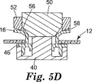
【0028】
図5Bにはパンチアセンブリ48が前進位置に示され、内側パンチ50の形成面56は対象物10の延長部材16の内部と接触している。より詳しくは、パンチ50の形成面56は、第1のパンチ50が前進されるときに延長部材16の円形状先端32の内部に接触するように、パンチ50の周囲に環状に延在する先細り面を含む。最初の接触後に内側パンチ50を前進させることによって、実質的に形成面56の傾斜に従う延長部材16の変形が引き起こされる。第1の内側パンチ50は、図5Cに示したように、その停止面54がダイ40の停止面44に接触するまで前進する。この前進の間、対象物10の延長部材16は、形成面56および外側パンチ52の端部に設けられた先細り形成面58の案内の下に連続的に変形される。上述のように、内側パンチ50の運動によって、外側パンチ52も同一の距離移動されることが好ましい。
【0029】
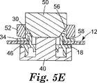
内側パンチ50がダイ40に対して停止されると、内側パンチ50に対する外側パンチ52の相対運動を引き起こすように外側パンチ52を作動することができる。外側パンチ52の連続的な前進運動は、図5Dに示したような対象物10の延長部材16のさらなる変形を引き起こす。この時点に、延長部材16の先端32は対象物10の基部18に向かって曲げ戻り始める。さらに、延長部材16に形成された湾曲部分30は、延長部材16が第1のパンチ50の形成面56に当接する箇所で明確に画定され始める。外側パンチ52のさらなる前進は、延長部材16がそれ自体の上に完全に折り曲げられるようにし、湾曲部分30が明確に規定される。次に、延長部材16の端部、その開口部14を囲む濾過材料12の一部分、および基部18は、外側パンチ52の先細り面58の内部先端とダイ40の金敷面46との間に挟まれることが好ましい。かくして、湾曲部分30は完全に画定され、径方向延在部分34は完成される。延長部材16の径方向延在部分34の取付け面36は、濾過材料12の第2の主面24に対して位置決めされ、その第1の主面22は基部18の表面20に対して位置決めされる。上述のように、好ましくは、第2の外側パンチ52によって用意される力は、径方向延在部分34と基部18との間に位置決めされる濾過材料12を少なくとも部分的に圧縮する程度に十分である。湾曲部分と径方向延在部分34が完全に画定されると、ダイ40によって支持された変形された部品10の位置からその部品を取り外すことができるように、内側および外側パンチ50と52は後退させることができる。換言すれば、変形された部品10は、今や有効に濾過材料12に接続されている。同一の操作順序は、他の濾過材料12に接続される次の要素10について実行することができるか、あるいは特定の工程および特定の用途に応じて同一の濾過材料12を使用できる。
【0030】
部品10の中央開口部26がない場合、ダイ40は部品10を通して延在する中央部分42を含まないであろう。さらに、停止面44が設けられない。部品10は、上述したのと同一の方法で変形できる本発明による延長部材16をなお含むであろう。延長部材16は管状であることができ、その平面図の形状は円形、長方形等のような任意の形状であり得る。内側パンチ50の運動は、例えば、その駆動装置またはシステム(図示せず)を制御することにより、簡単にその前進の程度を制御することによって他の任意の従来の手段によって制限できるであろう。さもなければ、変形工程は同一であり得る。
【0031】
部品10の中央開口部26がクロスブレースまたは他の要素のような他の構造的部品を含む場合には、ダイ40は、部品10を通して延在するための、およびストッパ面44を提供するためのダイの中央部分42をなお含み得る。しかし、中央部分42が部品10の中央開口部26の1つ以上の部分内をまたそれを通して十分に通過できるように、1つ以上のリリーフ領域(すなわち溝または切取り部分)を設けることが必要かもしれない。さもなければ、このようなリリーフ領域を有する中央部分42によっても、パンチおよびダイの運動を上述のように制限できる。
【0032】
内側パンチ50と外側パンチ52とをそれぞれ駆動するために、公知であるかあるいは開発された任意の適切な駆動機構を利用できる。各パンチを独立駆動し、好ましくは同期できるか、あるいは共通の駆動機構がそれらのパンチを共に移動でき、また外側パンチ52のさらなる延長を許容できる。例えば、共通の駆動装置は、空圧式、油圧式、電気的または機械的に駆動可能な単一のアクチュエータを含むことができ、このアクチュエータはパンチアセンブリ48と連動される。特に、このようなアクチュエータは、外側パンチのフルレンジの運動にわたって外側パンチを移動するように外側パンチ52と接続でき、また内側パンチ50はスリップまたは遊び許容手段によって外側パンチ52と連動できる。内側パンチ50が停止されるまで外側パンチ52の運動を内側パンチ50の運動に直接変換する程度に十分に堅いスプリング(図示せず)を、内側パンチ50と外側パンチ52との間に設けることができる。このようにして、内側パンチ50のストッパ面54がダイ40のストッパ面44に接触するとき、その運動は停止される。しかし、外側パンチ52は、それに取り付けられたアクチュエータの駆動下で前進し続けることができ、内側パンチ50に対する外側パンチの相対運動はスプリングまたは他の任意のスリップまたは遊び手段によって引き受けられる。
【0033】
また、図5A〜図5Eに概略的に示した変形操作を単一のパンチによって行い得ることも考えられる。すなわち、パンチが完全に前進した後に、延長部分の所望の形状を形成面それ自体が画定できる形成面を単一のパンチに設けることができる。上述の実施例のように、延長部分16の材料が十分に降伏するとき、パンチそれ自体の上に折り畳まれるようにパンチを前進させることができる。次に、さらなる前進はまた径方向延在部分34を画定できる。
【0034】
図1〜図5の延長部材16の代替的構成が図6と図7に示されている。部品の延長部材およびその基部の一部を画定する壁部の断面を示した部分断面図が示されている。特に、図6では、外側先端62および内側ペデスタル64を有する延長部材60が示されている。ペデスタル64から径方向外側にまた基部68の上方に部分的に延在する突出部66も設けることが好ましい。外側先端62とペデスタル64との間に、延長部材60の変形可能なセクション63が画定され、このセクションは、ペデスタル64から外側先端62のこのセクションの外面で先細りされることが好ましい。変形可能なセクション63を外側先端62に向かって先細りすることによって、延長部材60は外側先端62に向かってますます変形しやすくなる。さらに、変形可能な先細りセクション63は、射出成形のような成形工程によって部品を形成する機能を有利に容易にする。この構成は、部品を濾過材料に固定するために、上述した方法のような延長部材60の曲げ戻りを容易にする。ペデスタル64は、変形の完了後に部品の変形されない直立部分を提供するように、延長部材60の実質的に剛性のセクションを提供する。突出部66は、変形ステップの実行後に基部68に対して濾過材料を適所に保持するのを助けるように配慮することが好ましい。突出部66はまた、濾過材料の開口部14を画定する濾過材料の内縁とそれに取り付けられる部品との間の液密シールの形成を強化する。上述のように、好ましくは延長部材60、したがってその変形可能部分63、ペデスタル64および突出部66は、延長部材60の直交断面において一般的に円形である。
【0035】
図7では、外側先端72、変形可能部分73およびペデスタル74を有する延長部材70が示されている。図6の実施態様と同様に、変形可能部分73は、ペデスタル74からその部分の外面に沿って先端72に向かって先細りして、濾過材料の開口部への変形可能部分の挿入、変形可能部分の作製および基部78方向の変形可能部分の変形を容易にすることが好ましい。外側先端72から内側方向に変形可能部分73の内壁に沿って部分的に離間した点に溝76を設けることができ、この溝によって、上述のような取付け工程における延長部材70の曲げをさらに容易にする。変形可能部分73の外壁に第2の溝77を設けることも可能であり、前記外壁に隣接して前記溝はペデスタル74と接続して、延長部材70の曲げも容易にする。すなわち、溝76と77によって形成される薄化領域は、薄化領域のすぐ近くの領域よりも容易に降伏して、取付け工程中の延長部材70の曲げ箇所の点を画定するようにする。上述の最初の実施例に関して、溝77は湾曲部30の画定を容易にし、また溝76は、それに隣接して形成される湾曲ラインを画定することによって径方向延在部分34の形成を容易にする。ペデスタル74は、変形完了後に部品の変形されない直立部分を形成する。再び、延長部材70、したがってその変形可能部分73、ペデスタル74および溝76と77は、横断面で観測されるような概して円形に延在することが好ましい。図6と図7に示した修正は、選択的にまたは組み合わせて互いに利用し得ることをさらに指摘する。
【0036】
部品と濾過材料との間の代替的取付け構成が図8と図9に示されている。図8では、濾過材料12に接続された部品80が示されている。延長部材82は濾過材料12の開口部を通して設けられるが、濾過材料12の開口部は延長部材82の外径よりも小さく寸法決めされる。すなわち、濾過材料12の開口部にちょうど隣接するその材料の周辺部分は、例えば、対象物80が濾過材料12の開口部を通して挿入されるときに、延長部材82の外壁に沿って折り返される。濾過材料を折り返すことは、濾過材料12の固有の可撓性によって促進され得るか、あるいは開口縁部からのリリーフまたは切断を必要とし得る。いずれにしろ、延長部材82が部品80の基部84に向かって曲げて戻されて湾曲部分86を形成するとき、濾過材料12の周辺部分85は、径方向延在部分89と基部84との間に設けられることに加えて延長部材82の垂直部分87と88の間に間挿される。上述のように、周辺部分85を含む濾過材料12は、多層が含まれる場合にも気密取付け構成を提供するように少なくとも幾分圧縮されることが好ましい。この代替的構成は、図5A〜図5Eを参照して上述したのと同一の方法に従って形成されるが、変形操作の前に延長部材82の外壁の一部に沿って濾過材料12の周辺部分85を垂直に方向転換する追加ステップを伴う。
【0037】
当業者に十分に理解されるように、パンチおよびダイの構成は、任意の数の同様の修正を達成するように、パンチとダイの互いの間隔および互いの相対運動の程度に関して修正することができる。例えば、外側パンチ52を完全に前進させたとき、画定された湾曲部の両側の垂直部分が互いに近接して設けられるように、部品の延長部材が内側パンチ50の形成面56を最初に打つ点に近接して、上述の外側パンチ52の内側先端縁部を設けることができる。このことを利用して、その間の濾過材料周辺部分85のより大きな圧縮または押し潰しを行うことが可能である。上述のように、湾曲部86、垂直部分88および径方向延在部分89の形成は、その材料が標準温度で十分に可鍛性である(すなわち、破壊せずに可塑的に変形される能力を有する)ならば、延長部材82を冷間形成することによって実行し得るか、あるいは加熱によって熱形成し得る。
【0038】
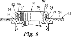
図9では、延長部材92を有する部品90は、図8を参照して上述したのと同様の方法で濾過材料12の開口部内に挿入される。その結果、濾過材料12の部分99は、湾曲部96によって分離される垂直部分97と98の間に間挿される。しかし、この構成は、径方向延在部分が形成されないという点において異なる。その代わりに、延長部材92の先端93の端面は、濾過材料12の第2の主面24に対して方向付けられて、部品90を濾過材料12に効果的に保持する。再び、このような構成は、図5A〜図5Eを参照して上述した方法に従って実施することができる。この場合、延長部材92の最初の長さは、湾曲部96を形成するとき、先端93が上述した方法で外側パンチ52のさらなる運動によって濾過材料12に方向付けられるように選択される。
【0039】
図8と図9に開示した修正が任意の数の方法および修正に利用し得ることが理解される。例えば、図9と同様の構成は、垂直部分97と98の間に設けられる濾過材料の部分99なしに形成できる。他の構成も意図され、この場合、このような部品の基部が濾過材料の第1の主面と少なくとも部分的に接触する間に、任意の部品の少なくともある部分の延長部材が濾過材料の第2の主面と接触する。
【0040】
上述のように、部品10は流体濾過材料12に取り付けられる任意の部品であり得る。さらに、部品10の延長部材が変形可能であるならば、上述のように、その変形が冷間工程または加熱形成工程として行うことができる任意の適切な材料から部品を形成することができる。好ましい材料は、例えばポリプロピレン、ポリエチレンまたはポリエステルのような降伏可能な熱可塑性のポリマを含む。これらのポリマは、冷間形成工程によってそれらを変形できるという点で好ましい。スチレン−ブタジエンのようなポリスチレンとコポリマとを含むより脆性の他の熱可塑性ポリマも使用可能であるが、それらは熱形成工程の部分として加熱をおそらく必要とするであろう。
【0041】
呼吸マスクの関連では、本出願の背景の項に述べているように、部品10は、呼吸器の呼気弁あるいは呼吸器ハーネスまたはアイシールド用の取付け部材の基部であり得る。呼吸マスクの作製では、濾過材料12は呼吸器本体(可撓性かつ折り畳み可能または予備形成のいずれにしろ)を典型的に提供し、また部品は基本的なマスク構造に特徴を加える。同じことが他の多くのタイプのフィルタについてしばしば当てはまり、例えば、真空掃除機と接続するためのフィルタ袋に取り付けられる流体入口/出口を含む真空掃除機用ごみ袋である。このことを考慮して、部品10および濾過材料12用の種々の可能な形態について記述し、提案した上述の取付け方法が利用できる広範囲の状態を説明する。
【0042】
図10と図11では、例えば、図12に示した折り畳み可能かつ可撓性の呼吸マスク102または図23に示した予め形成される呼吸マスク104のような呼吸マスクに本発明の方法で固定し得る呼気弁100が示されている。図10と図11に示した弁は、呼気弁100の周囲全体に延在することが好ましい基部107を含む弁本体106を具備する。基部107は上述の基部18と同様に機能し、呼吸マスク102の外面に寄り掛かるための表面108を含む。弁カバー110は弁本体106に永久的または取外し自在に取り付けでき、また空気を通すことができる開口部112を提供する。永久的な取付けは、例えば接着剤を塗布することによって、あるいは超音波溶接のような溶接技術によって達成できる。取外し可能な取付けは、例えば弾性クリップを使用することによって行うことができる。フラップ型弁が呼気中に開口部118を開口する一方向弁として機能するように、弁本体106は、弁開口部118を囲むシート面(図示せず)に寄り掛かる取付けフラップ型弁114(図23に図示)を含むことができる。このような弁は公知で商業的に入手可能であり、また米国特許第5,325,892号に記載されている。弁本体106および弁カバー110は、ポリプロピレン材料から典型的に形成される熱可塑性成形部品であることが好ましい。
【0043】
本発明によれば、弁本体106はまた、弁本体106から、また呼吸マスク102に対して位置する弁本体の表面108から離れて延在する延長部材116を含む。延長部材116が弁本体106と構造的に接続される方法は重要ではないが、延長部材116が構造的強度のために弁本体106と一体形成することが好ましい。さらに、中央開口部118が呼気弁100の流体の流動通路も画定するように、中央開口部118(すなわち円形、管状および中空)の周囲に延長部材116を位置決めすることも好ましい。図示したように、弁本体106の構造的完全性のための中央開口部118に交差して接続される構造的クロス部材120を設けることが可能であり、これによって、フラップ型弁114が中央開口部118に吸い込まれて戻るのを防止する。
【0044】
弁座面108および延長部材116を設けたことにより、呼気弁100は、図5A〜図5Eを参照して上述した方法で呼吸マスク102または104にこのようにして固定できる。特に、延長部材116は、呼吸マスク102または104に設けられる開口部を通して挿入され、この後に、上に述べたまたは提案した任意の方法で延長部材116を変形できる。さらに、呼気弁100は、マスクそれ自体が形成される前または後に呼吸マスク102または104に取り付け可能である。選択的にまたはインライン製造運転の部分として取付け操作を実行し得ることも考えられる。インライン取付け操作は、呼吸マスクの形成時にウェブに十分にアクセスできる製造ラインの任意の点で実行できる。
【0045】
折り畳み可能な呼吸マスク102が図12、図13、図14、図15に示されている。基本的に、このような呼吸マスク102は、略楕円形の中央パネル122と、上方および下方パネル124と126とを有するように画定される濾過材料を含む。呼気弁100は、中央パネル122に設けられる開口部128を通して取り付けることが好ましい。再び、弁本体106は延長部材116を含み、この延長部材は、図13から理解できるように、弁本体106の表面108と作用するように変形されて、呼気弁100を中央パネル122に固定する。マスク102が拡張されるようにパネル122、124、126が再構成されるとき、概してカップ形状のチャンバが着用者の鼻と口に合うべく画定されるように、呼吸マスク102は設計される。ヘッドバンド130は、中央パネル122の反対側長手方向端部の近くに取り付けられるようにすることがさらに好ましく、また図示したように、ヘッドバンドは、各部分がある長さの弾性材料を備える2部分ヘッドバンドを具備することが好ましい。ヘッドバンド130は、中央パネル122のようなパネルを形成する濾過材料にヒートシールまたは接着剤等によって従来の方法で固定できる。
【0046】
呼吸マスク102の利点は、上方および下方パネル124と126を中央パネル122の後方に折り畳んで格納するために平らに折り畳むことができる。折り畳まれた呼吸マスク102は図14と図15に示されている。呼吸マスク102のパネル122、124、126の各々は、内側および外側カバーウェブの間に位置決めされる濾過材料の少なくとも1つの層(すなわち、濾過材料を通過する空気から汚染物質を除去できる濾過材料の層)を典型的に含む。中央パネル122は補強材料層を有利に含むことも可能であり、同様に、上方パネル124は発泡材料の層を含み得る。図12〜図15に示したのと同様の呼吸マスクは国際公開特許出願番号WO96/28217およびWO97/32494に記述されている。
【0047】
図16では、折り畳み可能なタイプの呼吸マスクを作製するための形成工程が概略的に示されている。各製造ステップは、高速インライン工程を規定するように互いにインラインに実行することが好ましい。本発明によれば、この高速インライン工程は、他の工程ステップとインラインのおよび同一の運転速度による呼気弁のような部品の装着を有利に含むことができる。説明した方法によれば、マスク作製工程は、好ましくはこのような材料のロール形態の外側カバーウェブ材料200の供給から始まる。外側カバーウェブ材料200がシステムの機械方向に移動するとき、共に重ねられるいくつかの他の部品が前記外側カバーウェブに組み込まれて、積み重ねた層状材料から最終的に切断されるマスクを作製する。外側カバーウェブ200の上に加えられる第1の好ましい材料は、202において切断および塗布ステーション204に供給される。材料202は金属ストリップのような変形可能な材料を含むことが好ましく、この金属ストリップは、呼吸マスクに設けられる変形可能な鼻クリップの作製中にセクション206内に切り込んで入れることができる。これを行うために、外側カバーウェブ200に沿って離間した位置およびウェブ縁部の近くに、材料202の個別セクション206が加えられ、各呼吸マスク用に1つのセクション206が作製される。次に、補強材料208を連続的に供給して、カバーウェブ200の中央部分を覆う層を設けることが好ましい。鼻クリップ材料の離間したセクション206と、その上の補強材料208とを有する外側カバーウェブ200の頂部に、全幅の層の濾過材料210が設けられ、次に、内側カバーウェブ材料212が設けられる。この点に多層複合ウェブ214が形成され、このウェブから呼吸マスクを転換できる。種々の材料を互いに切断し、加え、重ねるための種々の操作は本発明の重要な特徴でなく、従来のまたは開発された任意の技術または方法は本発明に従って利用できることが指摘される。これらの操作は、高速製造工程が行われるようにインラインで実行されることが好ましい。
【0048】
複合ウェブ214が形成された後、溶接ステーション216、好ましくはヒートシール操作は、呼吸マスクの顔合わせ縁部になる外縁218と220(図18に図示)を画定するヒートシールラインを提供する。次に、発泡ストリップ材料222は、複合ウェブ材料214の上方に、特に、変形可能な鼻クリップ材料のセクション206の上方に連続的な材料として設けることが好ましい。図17では、ウェブ材料214および発泡ストリップ222の順次配置が、複合ウェブ材料214の頂面から矢印Aで示した機械方向に示されている。図示したウェブ材料の前縁(図17の底部)において、内側カバー材料212は、内側カバー材料を覆う連続層として発泡層222を含む。図の中央部分には、内側カバー材料212を付与する前の濾過材料が示され、この濾過材料210は、後縁に示したように、中央に配置された補強材料208と、その上の鼻クリップ材料のセクション206とを有する外側カバー層200を覆う。この点において、発泡ストリップ222および/または鼻クリップ材料のセクション206を内側カバーウェブ材料212または外側カバーウェブ200の外面に交互に位置決めし得るか、あるいは発泡ストリップ222を複合ウェブ材料214の構造に位置決めできることが指摘される。さらに、図示したような1つのみの層の代わりに濾過材料210の任意の数の層を設けることができる。
【0049】
次の転換ステップは、離間した平行な折り畳みライン226(図18にも図示)をスコアリング車輪が画定するスコアリングステーション224を含むことができ、このステップの目的は、順次作製される呼吸マスクを中央パネル228およびサイドパネル230と232に分割することである。切断ライン238と240(図18参照)それぞれにおいてヒートシールライン218と220のちょうど外側のウェブ材料を切断することによって、側縁リフーズストリップ236をトリムするための切断ステーション234が、スコアリングステーション224の後に用意される。開口部235は、切断ステーション234の各マスクの所定位置に対応する点においてウェブ材料を通して切断されることが好ましい。結果としてこの時点に得られるものは無数の呼吸マスクブランク237であり、各呼吸マスクブランクは開口部235を有し、共に一列に接続される。次に示したステーションは弁付けステーション242を具備することが好ましく、このステーションにおいて、呼気弁245は、他の製造操作部とインラインに各呼吸マスクブランク237に順次取り付けられる。このような弁付けステーション242によって呼気弁245を取り付ける方法は、以下により詳細に記述する。
【0050】
次に、弁245と順次接続される呼吸マスクブランク237は、折り畳みステーション244に前進させられ、これによって、サイドパネル230と232はそれぞれの折り畳みライン226において内側方向に折り畳まれて、順次接続される呼吸マスクブランク237を折り畳まれた状態で形成する。サイドパネル230が最初に上方に折り畳まれ、またサイドパネル232がサイドパネル230の頂部上方に折り畳まれるマスクブランク237の平面図が図19に示されている(図19に示し、以下に記述する他の特徴はさしあたり無視する)。
【0051】
次に、折り畳まれる呼吸マスクブランク270は、ステーション216と同様にヒートシール操作も含むことが好ましい他の溶接ステーション246に前進させられる。溶接ステーション246において、マスクブランク270は、それらが折り畳み状態にある間にライン248と250に沿って溶接される。このステップは、サイドパネル230と232それぞれの縁部218と220から離間されると共に概してそれら縁部に対応する円弧部分において、折り畳まれた側部230と232のウェブ材料とウェブ214の中央パネル228のウェブ材料とを溶接する。この操作によって、図14のマスクによって示したように(すなわち、サイドタブ付きの細長い楕円形のように)賦形されるマスクフロントパネルが画定され、また賦形されたフロントパネルは、使用可能なカップ形状の状態に広げることができる呼吸マスクを作製するようにサイドパネル230と232に接続される。
【0052】
次に、折り畳まれた各呼吸マスク270(なお直列に接続)は、ヘッドバンド材料254が各マスク270に加えられまた取り付けられるヘッドバンド取付けステーション252に前進させられる。特に、ヘッドバンド材料254は、図19にも示したように、一連の位置256と258において各マスク270に取り付けられ、この結果、個々のヘッドバンドは各マスク270に接続される。この取付けは、溶接操作によって、接着剤を塗布することによって、さもなければ機械的接続を行うことによって、各位置256と258で行うことができる。次に、最終の切断ステーション260は、折り畳まれた呼吸マスク270のストリップを画定する溶接ライン248と250の外側から余分な材料262(図19参照)をトリムする。
【0053】
切断ステーション260においても、ヘッドバンド材料254がマスク270に取り付けられる位置256と258の間の縁部264において、マスク270を少なくとも部分的に互いに分離することが好ましい。図16に示したように、各マスク270が余分な材料262から完全に切り取られるように、各マスク270は縁部264で完全に分離し得る。代わりに、マスク270は、ミシン目の線を切断するか、さもなければマスク270の間の弱い部分の線(図20参照)を画定することによって、部分的に縁部264で接続して残すことが可能である。次に、マスク270を使用するために容易に分離できる。共に接続されたマスク270を残す利点は、ロール形態でマスクを包装できることである。また、ヘッドバンド取付け位置256と258の間のヘッドバンド材料254の一部分は、図20に示したように互いに離間したヘッドバンドの縁部を残しつつ、切断または孔あけ工程中に取り外すことが可能である。代わりに、ヘッドバンドは縁部264に終端し得る。
【0054】
種々の任意の材料、すなわち、濾過層210、外側カバーウェブ材料200、内側カバーウェブ材料212、発泡材料222、補強材料208、鼻クリップ材料202およびヘッドバンド材料254のような材料を、図16に示した工程中に使用し得る。このような呼吸マスクを作製するために適切なある特定材料はWO96/28217に記載されており、その開示全体は参考として本出願に組み込まれている。代わりに、ヘッドバンド材料254はWO97/32493または米国特許第5,724,677号に記載されたようなものであることが可能であり、それらの開示全体も参考として本出願に組み込まれている。しかし、他の多くのヘッドバンド構成、デザインおよび取付け技術も、例えば、ステープルによってマスクに固定される2つの分離バンドを具備するヘッドバンドを含めて可能である。
【0055】
図12〜図15に示したマスク102のような呼吸マスクでごく一般的な濾過材料層は、電荷メルトブローミクロファイバ(BMF)の絡み合うウェブを含むことが多い。BMFファイバは、約10ミクロン(μm)以下の平均繊維直径を典型的に有する。ウェブにおいてランダムに絡み合うとき、ファイバはマットとして処理されのに十分な一体性を有する。マスク本体においてフィルタとして使用可能な繊維状材料の例は、米国特許第5,706,804号、第5,472,481号、第5,411,576号、および第4,419,993号に開示されている。繊維状材料は、米国特許第5,025,052号および第5,099,026号に記載された添加剤のような濾過性能を補強するための添加剤を含むことが可能であり、また性能を改善するために低レベルの抽出可能な炭化水素も有する。繊維状ウェブはまた、米国特許第4,874,399号に示されたようなより優れた耐油霧性を有するように製造し得る。例えば米国特許第5,496,507号、第4,592,815号、および第4,215,682号に記述された技術を用いて、不織布BMF繊維状ウェブに電荷を与えることができる。中央およびサイドパネルの外側および内側カバーウェブ(図12〜図15に示したマスク102の122、124、126で示したウェブ)は、濾過材料層を摩擦力から保護し、また濾過材料層から離れる可能性がある任意のファイバを保持する。カバーウェブは濾過能力も有し得るが、典型的に、濾過材料層の濾過能力ほど優れていない。カバーウェブは、例えば米国特許第4,807,619号および第4,536,440号に記載されたようなポリオレフィンとポリエステルとを含む不織布繊維性材料から作製し得る。
【0056】
開口部235を通して、接続された一連の呼吸マスクブランク237に弁245を取り付けできる方法について、図21と図22を参照して以下に記述する。以下の説明は、呼吸マスクが機械方向に停止せずに移動される間に、弁245を各呼吸マスクに取り付けできる方法に関する。すなわち、取付け方法は、弁付け操作を実行するために呼吸マスクの運動の停止を必要としないインライン操作を含むことが好ましい。しかし、それに代えて、接続された一連の呼吸マスクが停止される間に、弁付け操作を行い得ることが考えられる。さらに、上述のように、このような呼吸マスク、あるいは個別にまたは製造ラインの部分として濾過装置に転換される他の任意の濾過材料に弁付け操作を実行し得る。停止することなく、呼吸マスクブランク237に弁245を取り付けできる方法は、高速取付け操作および呼吸マスクの製造運転を実行できる点で好ましい。
【0057】
接続された一連の呼吸マスクブランク237は図16に示した弁付けステーション242に入るので、切断ステーション234の呼気弁取付け開口部235が前記マスクブランクに設けられている。さもなければ、各マスクブランク237の開口部235を切断するための独立した切断ステーションを弁付けステーション242内に設けることができるであろう。上述した弁付け方法と同様に、切断操作は、マスクブランク237が移動し続ける間に実行することが好ましい。製造運転中にインラインでおよび高速でこのような機能を実行するためのダイカット機構がよく知られている。特定のシステムと用途、および濾過材料が移動する間に切断操作を実行すべきかどうかに応じて、任意の適切な切断機構が考えられる。
【0058】
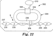
呼気弁取付け開口部235が設けられると、呼吸マスクブランク237は図22に示したように前進させられて、ガイドシステム304、パンチとダイアセンブリ306、弁ピックアップステーション308および弁フィーダ310を具備する弁付けステーション302に隣接して移動する。図21に概略的に示したように、ガイドシステム304は従来の構造であることが可能な上方ガイドトラック312を具備し、この上方ガイドトラックは、固定ガイドトラックとそれに沿って移動する転送機構(図示せず)とを含むことが好ましい。このような転送機構は、従来知られているような任意の方法で駆動可能なベルト、チェーン等を含み得る従来のまたは開発された任意の機構を具備することができる。ガイドシステム304は上方カムトラック314も具備し、この目的については以下に記述する。概略的にも示したように、ガイドシステム304はまた、好ましくは上方ガイドトラック312および上方カムトラック314と同様の構造の下方ガイドトラック316および下方カムトラック318を含むことが好ましい。
【0059】
上方ガイドトラック312の転送機構部分はパンチアセンブリ320に接続され、パンチアセンブリそれ自体は、図5A〜図5Eを参照して上述したのと同様の構造の内側パンチ322および外側パンチ324を含むことが好ましい。これによって、上方ガイドトラック312に沿ってパンチアセンブリ320を転送機構の速度で移動できる。さらに、上方カムトラック314は、同様に呼吸マスクブランク237が機械方向に移動される間に、パンチアセンブリ320をそれらのマスクブランクにおよびそこから離して移動する。特に、上方カムトラック314は、カムフォロア326が乗る表面を提供する。カムフォロア326は、例えば、パンチアセンブリ320の端部に回転して装着されるローラを具備することが可能であり、前記パンチアセンブリそれ自体は、それが転送機構によって移動される間にカムトラック314の通過を容易にするように、またカムトラックの通過に沿ったローラの乗りを許容するように構成される。図21から理解できるように、上方カムトラック314はカム部分315を含み、これによって、カムフォロア326、したがってパンチアセンブリ320は呼吸マスクブランク237に向かってまたそれから離れて移動される。この運動は、呼気弁245の変形および図5A〜図5Eを参照して上述した方法による呼気弁への前記呼吸マスクブランクの取付けに利用される。この運動はまた、上方ガイドトラック312の転送機構に摺動可能に装着されるパンチアセンブリ320によって促進される。
【0060】
下方ガイドトラック316の転送機構部分はダイアセンブリ328に接続され、このダイアセンブリは、取付け操作の前にダイアセンブリの上に弁部品を支持するための、およびパンチアセンブリ320と協働して取付け機能を実行するためのダイ部分を含む。ダイアセンブリ328はカムフォロア332も含み、このカムフォロアは、ダイアセンブリ328がその転送機構(図示せず)によって下方ガイドトラック316に沿って移動される間に、下方カムトラック318の表面に沿って乗る。上方カムトラック314と同様に、下方カムトラック318はカム部分319を含み、このカム部分によって、ダイアセンブリ328は、接続された呼吸マスクブランク237におよびそこから離して移動され、この運動はまた、呼気弁245の変形および呼吸マスクブランク237への呼気弁245の取付けに利用される。また、ダイアセンブリ328は下方ガイドトラック316の転送機構に摺動可能に接続される。取付け操作を効果的に実行するために、パンチアセンブリ320およびダイアセンブリ328は好ましくは互いに同期されかつ同様の速度で駆動され、また上方および下方カムトラック314と318のカム部分315と319それぞれは、取付け操作を実行するように相対位置決めされる。例えば、パンチアセンブリ320がカム部分315によって案内されるときにその形成位置に向かって移動するよりも早く、カム部分319によってダイアセンブリ328のその形成位置への前進開始が引き起こされ、またダイアセンブリがカム部分319によって案内されるときに移動するよりも早く、カム部分315によってパンチアセンブリ320の伸縮が引き起こされることが好ましい。これを行うために、カム部分319はカム部分315よりも長くなければならず、またカム部分315の両側でさらに遠くに延在するように位置決めすべきである。当然、さもなければ、任意の特定の形成操作に応じて、形成機構の一方の側面を他方の側面の前に前進できるか、あるいは両側を同時に前進できるように、カム部分315と319を互いに整列または位置決めできる。さらに、カム部分315と319によって促進される運動の程度は、十分な運動と力を供給して、変形操作およびマスクブランク237への呼気弁245の取付けを実行するように規定することが好ましい。上述のように、呼吸マスクブランク237を形成する材料のいくつかを少なくとも部分的に圧縮または押し潰して、気密接続の形成を強化するように、十分な力を用意することが好ましい。図5A〜図5Eを参照して上述したパンチアセンブリと同様に、内側パンチ322はスプリング(図示せず)のようなスリップまたは遊び手段によって外側パンチ324と連動されることが好ましく、この結果、内側パンチ322の運動を例えばダイ330によってより小さな運動に制限できる間に、外側パンチ324をカムフォロア326に駆動接続することができる。
【0061】
図22に示されているように、曲線状部分によって接続される直線部分を設けるように、細長い楕円形状のガイドシステム304を用意することができる。特定の所望の機能を実行できる限り他の形状が考えられる。弁ピックアップステーション308を第1の直線部分334に設けることが好ましく、その目的は、ダイ330がガイドシステム304の周囲に移動する間にダイの上に弁部品を装填することである。弁ピックアップステーション308に関連して、フィーダ310は連続量の部品を弁ピックアップステーション308に供給することが好ましい。弁ピックアップステーション308およびフィーダ310として利用される特定の機構は本発明の特定の部分を形成せず、また従来のまたは開発された装填および給送システムと機構を本発明に従って利用できることが考えられる。他の直線部分336は、呼吸マスクブランク237の運動とインラインに取付け操作を実行できるように、呼吸マスクブランクの機械方向と整列されることが好ましい。さらに、ダイアセンブリ328が各マスクブランク237の開口部235と整列して弁部品を供給するように、また直線部分336に沿って停止することなく変形ステップおよび取付け操作を完全に行うことができるように、マスクブランク237の機械速度をガイドシステム304の転送機構の速度と同期かつ整合しなければならない。さらに、上方および下方ガイドトラック312と316それぞれに沿って共通に駆動される複数のパンチおよびダイアセンブリ(すなわち、パンチアセンブリ320と同期ダイアセンブリ328との組合せ)を設けることが可能であり、この結果、1つ以上の取付け操作がガイドシステム304の直線部分336に沿って同時に進行し得ることが考えられる。これを容易にするために、直線部分336を適切に寸法決めすることができる。
【0062】
呼吸マスクブランク237の開口部235を通して呼気弁245を取り付けるために上述したような方法は、連続的および高速に実施できるので特に好ましい。取付け速度はマスク作製工程の機械速度と容易に同期できる。しかし、本発明による任意の方法は、濾過材料、または濾過材料を含むウェブ複合構造に部品を気密に効果的に取り付けできるという点で有利である。さらに、このような部品は、それが延在する開口部周囲の部品の内側に整然とした外観を有するように取り付けできるが、これは、剥き出しの縁部または溶接ラインが見られないからである。すなわち、変形工程により開口縁部が覆われる。さらに、部品と開口部との間の僅かな整列不良が隠され、また接続部が材料の両側に形成する効果的なシールを損なわない。さらに他の利点は、このような取付け工程から得られる機械的締付が、ウェブ材料を共に保持するように作用することである。このことは、部品取付けが複数の層を共に保持および/または微粒子損失の可能性を低減するように、ウェブ材料が複数の層を具備する場合、あるいはウェブ材料がその中に埋め込まれる微粒子を含む場合(炭素装入されたウェブが使用される場合)に、特に有利である。この作用はまた、層相互の液密シールを促進する。
【0063】
呼気弁を呼吸マスクに取り付けるための上述した本発明による方法の有効性を評価するために、図12〜図15に示したタイプのいくつかのマスクを、図16に示した工程に従って製作した。弁部品の基部および延長部材はポリプロピレン材料から形成され、また呼吸マスクの中央パネルは、ポリプロピレンスパンボンド不織布材料から成る内側および外側カバーウェブの間に設けられるBMF材料の層から構成される。各マスクの部品と中央パネルとの間のシールの品質は、呼気弁それ自体が閉位置にシールされたときに呼吸マスクの一方の側面から他方の側面に通過可能であった指標の流体量を測定することによって検査された。テストされた呼気弁は、図10と図11に示したタイプの呼気弁に含んでおり、この場合、フラップ型弁は各テスト毎に閉状態に維持された。流体の流量測定は、TSI Incorporated of Shoreview,Minnesota,U.S.A.から「CertiTest」モデル8130の商標名で入手可能なタイプの自動フィルタテスタを用いて行った。この器具によって、テストされたマスクおよび弁は、呼気弁が超音波溶接によってウェブ材料に取り付けられた同様のマスクと匹敵し得ることが確認された。
【0064】
上述のように、本発明による任意の取付け方法を利用して、材料またはマスクが完全に形成された後に任意の部品を任意の濾過材料または呼吸マスクに取り付け得ることも考えられる。図23に示した成形呼吸マスクに関して、例えば、着用者の口と鼻を覆うのに使用するための呼吸マスクのカップ形状の本体に、呼気弁100を予め形成した後に、呼気弁100を呼吸マスクに取り付け得る。このような予め形成されるマスクは公知であり、例えば米国特許第5,307,796号に記述されている。典型的に、マスク本体は、少なくとも1つの濾過材料層と、支持構造体をマスク本体に提供すると共に濾過層を支持するための賦形層とを具備する。賦形層は、従来の手順を用いてカップ形状に成形される任意の適切な材料、例えば熱接合可能な繊維の不織布ウェブから作製できる。典型的な特徴部は、図示したヘッドバンドストラップおよび鼻クリップを含む。いずれにしろ、成形工程前または後に本発明による方法を用いて呼気弁100を取り付けできるように、呼気アパーチャ(図示せず)が成形工程前または後に設けられる。
【0065】
また、本発明による任意の方法を利用して、呼吸マスクを他の分野で使用するために意図される濾過材料に他の部品を固定できる。例えば、図24では、真空掃除機で使用するためのフィルタ袋350に形成される空気濾過材料が示されている。このようなフィルタ袋は良く知られており、空気流を透過させる紙または他の材料から形成し得る。多層織物も良く知られている。図示したように、フィルタ袋350は、織物支持層354と356の間に設けられた濾過材料層352を具備する。入口358は、部品360を含むフィルタ袋350を通して画定され、前記部品は従来の方法でフィルタ袋350を真空掃除機の出口に取り付けるのを可能にする。部品360は、本発明による任意の方法によって適所に有利に固定でき、そのために、取付け操作に利用される上述の延長部材16と同様の変形可能な一体の延長部材(図示せず)が部品360に設けられる。部品360は、それが袋に形成される前または後に、それらの製造方法に応じて濾過材料に固定できるであろう。
【0066】
さらに、フィルタ370に接続された取付け部品372を有するフィルタを具備する他の濾過装置が図25に示されている。図示したフィルタ370は、再利用可能な呼吸マスクに取外し自在に取り付けられることが意図される使い捨て可能なフィルタを具備する。フィルタ370はディスク状であり、好ましくは溶接によってその周囲に縫合される多層ウェブ材料の円形ピースを具備する。このようなウェブ材料はスパンボンド材料層の間に位置決めされるミクロファイバ層を具備し、この層はフィルタ370の外面を形成する。図25に示した一般的なタイプのフィルタが公知であり、またこのような1つの例は、Minnesota Mining and Manufacturing Company of St.Paul,Minnesotaから「2040 High Efficiency Filter」の商標名で商業的に入手可能である。取付け部品372はスパンボンド材料の外層の1つに接続されることが好ましい。したがって、取付け部品372と内側ミクロファイバ層とを組み合わせる前に、外層の一方に接続することがさらに好ましい。特に、図25に示したように、スパンボンド層374は、取付け部品372が取り付けられる中央開口部を含む。ミクロファイバ層376はスパンボンド層374と取付け部品372の両方の開口部内側に見ることができる。本発明によれば、取付け部品372は延長部材を含み、この部材はスパンボンド層374の開口部を通して位置決めすることができ、またその背面に対して変形できる。さもなければ、取付け部品372それ自体が、その呼吸マスクまたは他のアイテムと取外し自在に接続可能にするために追加した特徴を所望するときに常にこの特徴を含む。
【0067】
濾過材料またはこのような濾過材料を有する任意の複合ウェブに部品を取り付ける必要がある場合、任意の数の異なる濾過装置および材料が考えられる。上述のように、濾過材料を含むため、濾過目的に対し有害な効果を与えないように、濾過材料を適所に固定して効果的なシールを提供するような方法による部品取付けが必要とされる。すなわち、取付け部は、流体の濾過が損なわれるような程度に相当の汚染物質が前記取付け部を通過できるのを許容してはならない。濾過材料を含むウェブの一方の側面に、提供される変形可能部分を含む任意の部品を取り付けるために、本発明による他の取付け方法も考えられ、この場合変形可能部分は、機械的締付による取付けが結果として得られるようにウェブの他方の側面に設けられる基部と共に利用できる。
【図面の簡単な説明】
【図1】 本発明による部品の取付け方法によって濾過材料に取り付けられる工程における部品の断面図である。
【図2】 濾過材料に取り付けられる工程の図1に示した部品の背面図である。
【図3】 図1と同様の断面図であるが、本発明による方法によって濾過材料に取り付けられた部品を示している。
【図4】 本発明による方法によって濾過材料に取り付けられた部品を示した図2と同様の背面図である。
【図5A】 本発明による1つの方法によって濾過材料に取り付けられる工程の順序における部品の概略図である。特に、本図は濾過材料層を通して設けられた開口部内に配置された部品を示しており、部品はまた、中央開口部とこの中央開口部を囲む延長部材とを含み、この延長部材によって部品は濾過材料に取り付けられ、および完全に開放した状態の形成パンチおよびダイ装置が示され、ダイは部品を支持するようにまた部品の中央開口部内に延在するように配置され、パンチは部品の延長部材から遠くに離間されている。
【図5B】本発明による1つの方法によって濾過材料に取り付けられる工程の順序における部品の概略図である。特に、本図は、濾過材料を通して配置された部品を示しており、パンチは部品の延長部材に接触して、それを変形させ始めるように前進される。
【図5C】本発明による1つの方法によって濾過材料に取り付けられる工程の順序における部品の概略図である。特に、本図は、濾過材料を通して配置された部品を示しており、パンチはダイの停止部分に接触するようにさらに前進され、部品の延長部材はさらに変形される。
【図5D】本発明による1つの方法によって濾過材料に取り付けられる工程の順序における部品の概略図である。特に、本図は濾過材料を通して配置された部品を示しており、ダイに接触するパンチおよびパンチの第2の構成要素は、部品に向かって延長部材を曲げて戻すために前進される。
【図5E】本発明による1つの方法によって濾過材料に取り付けられる工程の順序における部品の概略図である。特に、本図は、パンチの第2の構成要素のさらなる前進により濾過材料を通して配置されると共にそれに取り付けられる部品を示しており、これによって延長部材は部品に向かって十分に変形されて戻され、この結果、変形された延長部材の少なくとも表面部分は濾過材料に当接して、部品を濾過材料に機械的に締め付ける。
【図6】 図1〜図5の部品の延長部材の修正形態を示した拡大部分断面図であり、延長部は部品面からその先端に先細りし、濾過材料層への取付けを容易にするための突出部を有する。
【図7】 図6と同様の拡大部分断面図であり、延長部は部品面からその先端に先細りし、取付け工程中に形成される湾曲部を画定する弱い領域を設けるために画定された溝を含む。
【図8】 図3と同様であるが、濾過材料を部品に取り付ける方法の代替的構成を示している。
【図9】 図3と同様であるが、濾過材料を部品に取り付ける方法のもう1つの代替的構成を示している。
【図10】 本発明による呼吸マスクに接続するために適切な呼気弁の斜視図である。
【図11】 図10の呼気弁の背面図である。
【図12】 呼吸マスクに取り付けられ、ユーザの顔に位置決めされた図10と図11の呼気弁を示している。
【図13】 呼気弁を含む呼吸マスクの背面図であり、呼吸マスクは折り畳み型であり、広げた状態で示されている。
【図14】 前面からの図13の呼吸マスクの斜視図であり、呼吸マスクは折り畳まれた状態にある。
【図15】 背面からの図13の呼吸マスクの斜視図であり、呼吸マスクは折り畳まれた状態にある。
【図16】 図12〜図15に示したような呼吸マスクを作製するためのインライン工程の概略図であり、濾過材料層を含む複数の層からの呼吸マスクの生産とインラインで部品、すなわち呼気弁を呼吸マスクの各々に取り付けるための工程ステップを含む。
【図17】 図16の工程に従って構成されるタイプの呼吸マスクを作製するために適切な濾過材料を含む複合ウェブ材料を作製する際の層の順次形成を示した部分平面図である。
【図18】 図16の工程に従って呼吸マスクを作製する際の材料の部分平面図であり、呼吸マスクは、折り目ラインと側縁ヒートシールの形成後に部分的に形成されている。
【図19】 図16の工程に従って呼吸マスクを作製する際の材料の部分背面図であり、呼吸マスクは大部分形成され、ヘッドバンド材料は呼吸マスク上に位置決めされ、それに接続されている。
【図20】 図16の工程に従って形成された複数の呼吸マスクの部分背面図であり、呼吸マスクは完全に形成されているが、なお互いに取り付けられている。
【図21】 パンチおよびダイ装置と、本発明による呼吸マスク作製工程とインラインで部品を取り付けるための前記装置の制御方法とを示した図16の工程の一部の概略図である。
【図22】 図21に示した工程部分の平面概略図である。
【図23】 部品、すなわち呼気弁と組み合わせた成形タイプの呼吸マスクの正面図であり、部品は本発明による方法によって成形される呼吸マスクに取り付けることができる。
【図24】 フィルタ袋材料の開口部を通して取り付けられた部品を含む、真空掃除機内で使用可能なタイプのフィルタ袋を示し、部品は本発明による方法によってフィルタ袋に取り付けることができる。
【図25】 本発明による方法によってエアフィルタに取り付けられた部品を含む呼吸マスクに使用できるエアフィルタの片側面図である。[0001]
Technical field
The present invention relates to a method for attaching one or more component elements to a filtering material comprising such a material of a type particularly suitable for use in making a respiratory mask. In particular, the present invention relates to a method of attaching one or more parts to a filtering material, where the preferred method is a method suitable for automated production as part of a high speed manufacturing system. The present invention relates to a combination of parts and filtration material that are attached together according to the method of the present invention. Typical components attached to the respiratory mask include, for example, valves, headbands, and the like.
[0002]
Background of the Invention
The filtering material can be incorporated into any number of different types of filters and / or can be formed or otherwise configured in a filtering device. In any case, it may be desirable to attach the component elements to the filtration material to facilitate the incorporation of other elements into the filtration material or when the filter material is configured as a filtration device. The filtering material itself typically includes a medium that allows fluid flow through the medium but can define orifices or passages in the medium that restrict the passage of particulate matter and the like through the filter medium. . Otherwise, such media may replace or in addition to particulate removal (ie by suction or chemical reaction) to remove any component of the fluid from the fluid as it passes through the filtration media. Can be designed to.
[0003]
The present invention has been developed specifically for the production of respirators used in a wide variety of applications to protect a user's respiratory system from airborne contaminants and / or unpleasant or unpleasant gases. Furthermore, the therapist utilizes such a respiratory mask to prevent the spread of harmful microorganisms to or from the therapist.
[0004]
Various forms of respiratory masks are commercially available, some of which are classified as “disposable” because they are intended to be used for a relatively short period of time. Other non-disposable breathing masks can include a replaceable filter, although the masks themselves are reusable. Disposable masks typically have a mask body that is primarily formed from air filtration material, and the mask body is shaped or configurable to fit at least a person's nose and mouth. . Replacement filters for non-disposable masks typically include a layer of air filtration material with structural components to which the filter and reusable mask can be connected.
[0005]
Disposable breathing masks can generally be classified into one of several categories, some of which are described as follows. 1) A flat flexible mask that is sometimes folded or pleated and dimensioned to fit relatively flat on a person's nose and mouth, 2) Folds flat, and the mask is in the person's nose and mouth A foldable mask that can be expanded into a cup-shaped ready-to-use condition that can fit into the 3), and a molded mask that is pre-formed into those usable conditions. Of these, any type of mask that folds flat can be bundled flat and can be provided with appropriate seams, pleats and / or folds to accommodate use. A foldable type mask that can be expanded into a cup-like state is typically formed by panels defined by seams, pleats and / or folds that allow the mask to be opened in a generally cup-like shape. On the other hand, the molding mask is preformed to the desired face-fit shape and generally retains that shape during use. When a flat folded or molded mask is used, the mask body forms at least some breathing zone at least around the nose and mouth of the wearer. As the wearer inhales, air is drawn into the breathing zone through the air filtering material.
[0006]
Disposable breathing masks generally incorporate at least one attached component that is attached to or through a filter material layer or a composite material having a filter material layer. For example, almost all such masks include a headband, string or other means that can secure the mask to the user's head. In addition, such masks are also known to incorporate other attachments including valves, nose clips and face shields.
[0007]
One method often used to attach such parts is based on the use of thermal or ultrasonic welding as described, for example, in US Pat. No. 5,325,893. These methods are advantageous in that such parts can be attached so that the parts are effectively sealed by the filtering material. That is, since the entire circumference of the part can be welded, the filtering material, possibly a fibrous material, can be thermoplastically welded to itself and the part. Thus, the part can be sealed against the filtering material so that the filtering effect of the filtering material is not impaired at the mounting interface. However, welding techniques require the provision of relatively complex equipment to perform ultrasonic or heat treatment, and are sufficient to ensure good mounting results, especially when fibrous materials are connected to the parts. It is generally more expensive and complex than others in that it requires a control system.
[0008]
Instead, the use of adhesive bonding is known for certain parts and other forms of respiratory organs. The advantage of adhesive bonding is that, like welding, effective attachment can be made easier. That is, as long as the adhesive is compatible with both the filtering material and the part, the adhesive can be applied over the entire periphery of the part to form an excellent attachment. However, the seal formed by this attachment is reinforced only where the adhesive is applied. That is, an outer layer (which can be a filter material or other) can be attached and sealed to the part with an adhesive, but the other layers may not be sealed to each other with the outer layer or part. Thus, a good seal (ie, a seal that does not allow larger particles to pass through, for example, is a filter function) can be compromised. In any case, such an adhesive application technique requires additional expense of the adhesive and also requires provision of means to distribute and control the application of the adhesive. This adds cost and complexity.
[0009]
In other situations, mechanical clamping techniques including the use of fasteners such as staples or other clamping structures are also known. Such mechanical systems have the general advantage in that they do not require heat and / or ultrasonic generators and controllers, or complex joining devices such as adhesive dispensing and application devices and controllers. Have. However, on the other hand, the mechanical clamping system itself may instead require complex alignment and control mechanisms. Examples of mechanical mounting techniques are disclosed in US Pat. Nos. 5,374,458 and 5,080,094, and published international applications WO 96/11594 and 96/28217. Of greatest concern when utilizing mechanical fasteners or fastening systems is the formation of an effective seal, i.e. a seal that does not allow the passage of significant amounts of contaminants, which would otherwise be part This problem, which is intended to be removed by the attached filtering material, is where the part is attached on the mask (for example, a location directly in front of the user's nose as opposed to away from the side of the nose) Can vary depending on Furthermore, certain mechanical clamping methods may require not only the provision of additional fastening parts, but also additional alignment steps and fastener or clamping operation steps.
[0010]
These attachment methods are also used in other fields when it is necessary to secure a part to a fluid filtering material, for example when manufacturing air filters and oil filters such as vacuum cleaner garbage bags. Examples of mechanical clamping techniques utilized outside the field of fluid filtration are disclosed in U.S. Pat. Nos. 4,909,434, 5,125,886 and 5,199,635, in which Mechanical clamping is used to secure the spout to the liquid container (in combination with heat sealing in some cases).
[0011]
Summary of the present invention
The present invention overcomes the deficiencies and disadvantages of the prior art by providing a suitable mechanical attachment technique to form an effective seal between the filtration material and the part for attaching the part to the filtration material. Overcome. Furthermore, the present invention includes such techniques that can be implemented as part of an in-line production system and that are particularly available in high-speed production lines.
[0012]
Furthermore, the method of the present invention comprises a part attached to a filtration material having a base side, and passing at least an extension member through the filtration material and in contact with the filtration material, or at least a portion of the extension member or the base of the extension member By having a composite portion that includes a material side that is separate from the side, an extension member is utilized that is used in clamping the part to the filtration material. The extension member is preferably provided through the material and is in contact with the other side of the material over the entire circumference of the opening through which the extension member passes to form a fully effective seal around the part.
[0013]
The method of the present invention inserts the extension member of the part through the opening in the material and then causes sufficient deformation of the extension member to make sufficient contact with the material so as to form an effective seal between the part and the material. Performing a deforming step to cause the extension member to have a surface. The material is deformed and part base so that an effective seal is reinforced during the deformation step, especially if the filtering material is a composite web comprising two or more layers (so that the layers seal together) Is preferably at least partially compressed.
[0014]
Such techniques and methods of attaching the part to the filtration material allow this to be done with a mechanical clamping device that is effective to provide an effective seal with the filtration material with minimal system complexity. It is particularly advantageous in that it can be attached to a simple filter material relatively easily. The method of the present invention positions the extension member at the same time that the part is positioned on the filtering material, so there is no need to provide additional parts that must be handled and positioned in addition to the part. Preferably, the extension member is made integrally with the part. The deformation step can be performed as a cold forming process without applying heat, or as part of a heat or heat forming process, depending on the material from which the extension of the part is made. The method of the present invention is particularly adaptable for use as part of an in-line production system that can be implemented at relatively high speeds.
[0015]
More specifically, the present invention relates to providing an alternative method of attaching an exhalation valve to an air filtration material that forms part of a part, eg, a respiratory mask.
[0016]
The aforementioned advantages of the present invention can be achieved by providing a part and a web comprising a filtering material, wherein the part is attached to a web comprising first and second major surfaces and an opening, and the part is At least a portion of the base comprising a base disposed against the first major surface of the material and an extension member extending from the base through the opening and having a deformed portion of the extension member folded back toward the base Is placed against the second major surface of the fluid filtration material so as to mechanically clamp the part in a fluid tight relationship with the material. The filter material is preferably at least somewhat compressed in the attachment state between the part and the web.
[0017]
The present invention also provides a method of making a combination of a web and a part as described above, wherein the method includes a web comprising a filtration material layer having first and second major surfaces and an opening. Providing a part having a base and a deformable extension member extending from the base, and a part relative to the first major surface of the web having the extension member extending through the opening Positioning the base; deforming the extension member back toward the base so that at least a portion of the extension member abuts the second major surface of the web and clamps the part in a fluid-tight relationship with the material; including.
[0018]
Detailed Description of the Preferred Embodiment
Referring to the drawings in which like components have like reference numerals throughout the several views, a method of attaching a
[0019]
As shown in FIG. 1, the
[0020]
The
[0021]
As shown in FIG. 2, the
[0022]
In accordance with the present invention, the
[0023]
To enhance the fluid tight seal, the
[0024]
It is also conceivable to fix the
[0025]
FIG. 4 shows the
[0026]
One particular method that can be utilized to deform the
[0027]
Beginning with FIG. 5A, the
[0028]
In FIG. 5B, the
[0029]
When the
[0030]
Without the
[0031]
If the
[0032]
Any suitable drive mechanism known or developed may be utilized to drive the
[0033]
It is also conceivable that the deformation operation schematically shown in FIGS. 5A to 5E can be performed with a single punch. That is, after the punch has been fully advanced, a single punch can be provided with a forming surface that allows the forming surface itself to define the desired shape of the extension. As in the above-described embodiment, when the material of the
[0034]
Alternative configurations of the
[0035]
In FIG. 7, an
[0036]
An alternative mounting configuration between the part and the filtering material is shown in FIGS. In FIG. 8, a
[0037]
As will be appreciated by those skilled in the art, the punch and die configuration may be modified with respect to the distance between the punch and die and the degree of relative movement with respect to each other to achieve any number of similar modifications. it can. For example, when the
[0038]
In FIG. 9, a
[0039]
It will be appreciated that the modifications disclosed in FIGS. 8 and 9 may be utilized for any number of methods and modifications. For example, a configuration similar to FIG. 9 can be formed without a portion 99 of filtering material provided between the
[0040]
As described above, the
[0041]
In the context of a respiratory mask, as described in the background section of this application, the
[0042]
10 and 11, for example, a foldable and flexible
[0043]
In accordance with the present invention, the
[0044]
By providing the
[0045]
A foldable
[0046]
The advantage of the
[0047]
In FIG. 16, the forming process for making a foldable type respiratory mask is schematically shown. Each manufacturing step is preferably performed in-line with each other to define a high-speed in-line process. In accordance with the present invention, this high speed inline process can advantageously include the mounting of components such as an exhalation valve inline with other process steps and at the same operating speed. According to the described method, the mask making process begins with the provision of an outer
[0048]
After the
[0049]
The next diversion step can include a scoring station 224 in which scoring wheels define spaced parallel fold lines 226 (also shown in FIG. 18), the purpose of which is to sequentially produce a respiratory mask. Dividing into a
[0050]
Next, the breathing mask blank 237, which is sequentially connected to the
[0051]
The folded respirator blank 270 is then advanced to another
[0052]
Each folded respirator 270 (still connected in series) is then advanced to a
[0053]
Also at the cutting
[0054]
Various optional materials, such as
[0055]
A very common layer of filtration material in a respirator, such as the
[0056]
The manner in which
[0057]
Since the connected series of
[0058]
Once the exhalation
[0059]
The transfer mechanism portion of the
[0060]
The transfer mechanism portion of the
[0061]
As shown in FIG. 22, an elongate
[0062]
The method as described above for attaching the
[0063]
In order to evaluate the effectiveness of the method according to the invention described above for attaching an exhalation valve to a respiratory mask, several masks of the type shown in FIGS. 12 to 15 were produced according to the process shown in FIG. The base and extension members of the valve component are formed from polypropylene material, and the center panel of the breathing mask is composed of a layer of BMF material provided between the inner and outer cover webs of polypropylene spunbond nonwoven material. The quality of the seal between each mask part and the center panel is the amount of fluid in the indicator that was allowed to pass from one side of the breathing mask to the other when the exhalation valve itself was sealed in the closed position. Inspected by measuring. The expiratory valves tested included in the expiratory valves of the type shown in FIGS. 10 and 11, where the flap type valve was kept closed for each test. Fluid flow measurement is described in TSI Incorporated of Shoreview, Minnesota, U.S.A. S. A. Using an automatic filter tester of the type available under the trade name “CertiTest” model 8130. This instrument confirmed that the tested masks and valves could be comparable to similar masks where the exhalation valve was attached to the web material by ultrasonic welding.
[0064]
As discussed above, it is contemplated that any attachment method according to the present invention may be utilized to attach any part to any filtration material or respiratory mask after the material or mask has been completely formed. 23, for example, after the
[0065]
Also, any method according to the present invention can be utilized to secure other components to the filtering material intended for use in other areas of the respiratory mask. For example, FIG. 24 shows an air filtration material formed on a
[0066]
In addition, another filtration device comprising a filter having a mounting
[0067]
Any number of different filtration devices and materials are contemplated when it is necessary to attach the component to a filtration material or any composite web having such a filtration material. As mentioned above, the inclusion of filtering material requires component mounting in such a way as to secure the filtering material in place and provide an effective seal so as not to have a detrimental effect on the filtering purpose. . That is, the attachment must not allow substantial contaminants to pass through the attachment to such an extent that fluid filtration is impaired. Other attachment methods according to the invention are also conceivable for attaching any part including the provided deformable part to one side of the web containing the filtering material, in which case the deformable part is by mechanical clamping It can be utilized with a base provided on the other side of the web so that attachment is obtained.
[Brief description of the drawings]
FIG. 1 is a cross-sectional view of a part in a process of being attached to a filtering material by the part attaching method according to the present invention.
FIG. 2 is a rear view of the component shown in FIG. 1 during the process of attaching to the filtering material.
FIG. 3 is a cross-sectional view similar to FIG. 1, but showing the parts attached to the filtering material by the method according to the invention.
FIG. 4 is a rear view similar to FIG. 2, showing the parts attached to the filtering material by the method according to the invention.
FIG. 5A is a schematic illustration of parts in a sequence of steps that are attached to a filtering material by one method according to the present invention. In particular, the figure shows a part disposed in an opening provided through the layer of filtration material, the part also including a central opening and an extension member surrounding the central opening, by which the part is A forming punch and die device attached to the filtering material and fully open is shown, the die being positioned to support the part and extend into the central opening of the part, and the punch is an extension of the part It is spaced far from the member.
FIG. 5B is a schematic illustration of parts in a sequence of steps that are attached to a filtering material by one method according to the present invention. In particular, the figure shows the part placed through the filtering material, and the punch is advanced to contact the extension member of the part and begin to deform it.
FIG. 5C is a schematic view of parts in a sequence of steps that are attached to a filtering material by one method according to the present invention. In particular, this figure shows the part placed through the filtering material, the punch being further advanced to contact the stop portion of the die, and the extension member of the part being further deformed.
FIG. 5D is a schematic illustration of parts in a sequence of steps that are attached to a filtering material by one method according to the present invention. In particular, the figure shows the part placed through the filtering material, and the punch and the second component of the punch contacting the die are advanced to bend the extension member back toward the part.
FIG. 5E is a schematic illustration of parts in a sequence of steps that are attached to a filtering material by one method according to the present invention. In particular, this figure shows the part placed through and attached to the filtering material by further advancement of the second component of the punch, whereby the extension member is fully deformed back towards the part, As a result, at least the surface portion of the deformed extension member abuts against the filter material and mechanically clamps the component to the filter material.
FIG. 6 is an enlarged partial cross-sectional view showing a modified form of the extension member of the component shown in FIGS. 1 to 5, in which the extension portion tapers from the component surface to the tip thereof to facilitate attachment to the filter material layer. With protrusions.
FIG. 7 is an enlarged partial cross-sectional view similar to FIG. 6, with the extension tapering from the component surface to its tip, and a groove defined to provide a weak region that defines the curvature formed during the mounting process. including.
FIG. 8 is similar to FIG. 3, but shows an alternative configuration of the method of attaching the filtering material to the part.
FIG. 9 is similar to FIG. 3, but illustrates another alternative configuration of a method of attaching the filtering material to the part.
FIG. 10 is a perspective view of an exhalation valve suitable for connection to a respiratory mask according to the present invention.
FIG. 11 is a rear view of the exhalation valve of FIG.
12 shows the exhalation valve of FIGS. 10 and 11 attached to a respiratory mask and positioned on the user's face. FIG.
FIG. 13 is a rear view of a respiratory mask including an exhalation valve, the respiratory mask being folded and shown in an unfolded state.
14 is a perspective view of the respiratory mask of FIG. 13 from the front, with the respiratory mask in a folded state. FIG.
15 is a perspective view of the respiratory mask of FIG. 13 from the back, with the respiratory mask in a folded state. FIG.
FIG. 16 is a schematic diagram of an in-line process for making a respirator as shown in FIGS. 12-15, in-line with the production of a respirator from multiple layers including a layer of filtration material, ie exhaled Process steps for attaching a valve to each of the respiratory masks.
17 is a partial plan view showing the sequential formation of layers in making a composite web material that includes a suitable filtering material to make a type of respiratory mask constructed according to the process of FIG.
FIG. 18 is a partial plan view of a material when making a respirator according to the process of FIG. 16, where the respirator is partially formed after the formation of crease lines and side edge heat seals.
FIG. 19 is a partial rear view of the material in making a respiratory mask according to the process of FIG. 16, wherein the respiratory mask is largely formed and the headband material is positioned on and connected to the respiratory mask.
20 is a partial rear view of a plurality of respiratory masks formed according to the process of FIG. 16, wherein the respiratory masks are fully formed but are still attached to one another.
FIG. 21 is a schematic diagram of a portion of the process of FIG. 16 showing the punch and die apparatus, the respiratory mask making process according to the present invention, and the method of controlling the apparatus for mounting components in-line.
22 is a schematic plan view of the process portion shown in FIG. 21. FIG.
FIG. 23 is a front view of a molded type respiratory mask in combination with a component, an exhalation valve, which can be attached to a respiratory mask molded by the method according to the present invention.
FIG. 24 shows a filter bag of the type that can be used in a vacuum cleaner, including a part attached through an opening in the filter bag material, which part can be attached to the filter bag by the method according to the invention.
FIG. 25 is a side view of an air filter that can be used with a respiratory mask that includes components attached to the air filter by the method according to the present invention.
Claims (7)
(b)前記第1の主面と接触する面を有する基部と、前記基部から前記開口を通じて延在する管状の延長部材を備える呼気弁とを備え、
前記延長部材は、前記マスク本体に接触する変形部分を有し、前記変形部分によって、前記延長部材の一部が前記マスク本体の一部に沿って、前記第1及び第2の主面に対して相対的に折り返され、前記延長部材の一部が第2の主面に当接する、
呼吸マスク。(A) a mask body having first and second main surfaces facing each other and openings provided in the first and second main surfaces, and comprising a filtration material layer formed in a sheet shape;
(B) a base having a surface in contact with the first main surface, and an exhalation valve including a tubular extension member extending from the base through the opening;
The extension member has a deformed portion that comes into contact with the mask body, and the deformed portion causes a part of the extension member to extend along a part of the mask body with respect to the first and second main surfaces. relatively folding is returned Te, a portion of the extension member abuts against the second major surface,
Breathing mask.
シート状に形成された濾過材料層を具備するマスク本体であって、互いに対向する第1および第2の主面と前記マスク本体を貫通する開口部とを有する前記マスク本体を用意するステップと、
表面を有する呼気弁基部と、前記呼気弁基部から先端まで延在する変形可能な延長部材とを具備する呼気弁を用意するステップと、
最初に前記マスク本体内の前記開口部を通して前記延長部材の先端を挿入して、前記開口部を通して前記延長部材を延在させるとともに、前記マスク本体の前記第1の主面に対して前記呼気弁基部の前記表面を接触させるステップと、
次に、前記延長部材の少なくとも表面が前記マスク本体の前記第2の主面に当接するように、前記呼気弁基部に向かって折り返して前記延長部材を変形させ、前記呼気弁基部の前記表面と前記マスク本体の前記第1の主面とを接触させると共に、前記マスク本体と液密関係に前記呼気弁を締め付けるステップとを含む方法。A method of manufacturing a respiratory mask, wherein an exhalation valve is attached to the mask body,
Providing a mask body having a filter material layer formed in a sheet shape, the mask body having first and second main surfaces facing each other and an opening penetrating the mask body;
Providing an exhalation valve comprising a exhalation valve base having a surface and a deformable extension member extending from the exhalation valve base to a tip;
First, the distal end of the extension member is inserted through the opening in the mask body to extend the extension member through the opening, and the exhalation valve with respect to the first main surface of the mask body Contacting the surface of the base;
Next, the extension member is folded back toward the exhalation valve base so that at least the surface of the extension member is in contact with the second main surface of the mask body, and the surface of the exhalation valve base is Contacting the first major surface of the mask body and tightening the exhalation valve in a fluid tight relationship with the mask body.
濾過材料層を具備するウェブ材料を用意するステップと、前記ウェブ材料を一連の折り畳み可能な呼吸マスクに転換するステップと、呼気弁を各呼吸マスクに取り付けるステップを含み、複数の前記呼気弁の各1つを複数の前記呼吸マスクに取り付ける前記方法が、
マスク本体の第1の主面から前記マスク本体を通して、前記第1の主面に対向する前記マスク本体の第2の主面まで開口部を設けるステップと、
表面を有する呼気弁基部と、前記呼気弁基部から先端まで延在する変形可能な管状の延長部材とを具備する呼気弁を用意するステップと、
前記マスク本体内の開口部を通して前記呼気弁の延長部材を最初に先端を挿入して、前記開口部を通して前記延長部材を延在させるとともに、前記マスク本体の前記第1の主面に対して前記呼気弁基部の前記表面を接触させるステップと、
次に、前記延長部材の少なくとも表面が前記マスク本体の前記第2の主面に当接するように、前記呼気弁基部に向かって折り返して前記延長部材を変形させ、前記呼気弁基部の前記表面と前記マスク本体の前記第1の主面とを接触させると共に、前記呼気弁を前記マスク本体と液密関係に締め付けるステップと、を含む方法。An in-line method of manufacturing a plurality of foldable respirators that can be folded to form a cup shape that folds flat and creates an open volume around at least a portion of a wearer's face, comprising:
Providing a web material comprising a layer of filtration material; converting the web material into a series of foldable breathing masks; and attaching an exhalation valve to each breathing mask; The method of attaching one to a plurality of the respiratory masks;
Providing an opening from the first main surface of the mask main body through the mask main body to the second main surface of the mask main body facing the first main surface;
Providing an exhalation valve comprising a exhalation valve base having a surface and a deformable tubular extension member extending from the exhalation valve base to a tip;
The tip of the exhalation valve extension member is first inserted through the opening in the mask body to extend the extension member through the opening, and the first main surface of the mask body is Contacting the surface of the exhalation valve base;
Next, the extension member is folded back toward the exhalation valve base so that at least the surface of the extension member is in contact with the second main surface of the mask body, and the surface of the exhalation valve base is Contacting the first main surface of the mask body and tightening the exhalation valve in a fluid tight relationship with the mask body.
Applications Claiming Priority (3)
| Application Number | Priority Date | Filing Date | Title |
|---|---|---|---|
| US09/420,671 US6604524B1 (en) | 1999-10-19 | 1999-10-19 | Manner of attaching component elements to filtration material such as may be utilized in respiratory masks |
| US09/420,671 | 1999-10-19 | ||
| PCT/US2000/008044 WO2001028634A1 (en) | 1999-10-19 | 2000-03-24 | Manner of attaching component elements to filtration material such as may be utilized in respiratory masks |
Publications (3)
| Publication Number | Publication Date |
|---|---|
| JP2003512104A JP2003512104A (en) | 2003-04-02 |
| JP2003512104A5 JP2003512104A5 (en) | 2007-05-10 |
| JP4627396B2 true JP4627396B2 (en) | 2011-02-09 |
Family
ID=23667399
Family Applications (1)
| Application Number | Title | Priority Date | Filing Date |
|---|---|---|---|
| JP2001531461A Expired - Fee Related JP4627396B2 (en) | 1999-10-19 | 2000-03-24 | Attaching the component elements to the filtering material available in the respiratory mask |
Country Status (10)
| Country | Link |
|---|---|
| US (4) | US6604524B1 (en) |
| EP (2) | EP1224011B1 (en) |
| JP (1) | JP4627396B2 (en) |
| KR (1) | KR100661936B1 (en) |
| AT (2) | ATE451148T1 (en) |
| AU (1) | AU772555B2 (en) |
| BR (1) | BR0014807B1 (en) |
| DE (2) | DE60043518D1 (en) |
| MX (1) | MXPA02003845A (en) |
| WO (1) | WO2001028634A1 (en) |
Families Citing this family (76)
| Publication number | Priority date | Publication date | Assignee | Title |
|---|---|---|---|---|
| US6604524B1 (en) * | 1999-10-19 | 2003-08-12 | 3M Innovative Properties Company | Manner of attaching component elements to filtration material such as may be utilized in respiratory masks |
| US7743920B1 (en) * | 2001-10-10 | 2010-06-29 | Ric Investments, Llc | Patient interface packaging with integrated sizing gage |
| EP2266651B1 (en) * | 2002-02-04 | 2013-07-10 | Fisher & Paykel Healthcare Limited | Breathing assistance apparatus |
| US7188622B2 (en) * | 2003-06-19 | 2007-03-13 | 3M Innovative Properties Company | Filtering face mask that has a resilient seal surface in its exhalation valve |
| US8783257B2 (en) | 2004-02-23 | 2014-07-22 | Fisher & Paykel Healthcare Limited | Breathing assistance apparatus |
| ES2703450T3 (en) | 2004-04-02 | 2019-03-08 | Fisher & Paykel Healthcare Ltd | Breathing assistance device |
| US7360538B2 (en) * | 2005-07-18 | 2008-04-22 | Stephen Flynn | Oxygen therapy face mask |
| US20070068529A1 (en) * | 2005-09-27 | 2007-03-29 | Suresh Kalatoor | Respirator that uses a polymeric nose clip |
| US7503326B2 (en) | 2005-12-22 | 2009-03-17 | 3M Innovative Properties Company | Filtering face mask with a unidirectional valve having a stiff unbiased flexible flap |
| ES2954589T3 (en) | 2006-07-14 | 2023-11-23 | Fisher & Paykel Healthcare Ltd | Respiratory assistance device |
| US20080099022A1 (en) * | 2006-10-26 | 2008-05-01 | 3M Innovative Properties Company | Respirator That Uses A Predefined Nose Foam Shape |
| KR100690592B1 (en) * | 2006-10-31 | 2007-03-12 | 장정산업 주식회사 | Plucking machine of ear band for a dustproof mask |
| US20080271739A1 (en) | 2007-05-03 | 2008-11-06 | 3M Innovative Properties Company | Maintenance-free respirator that has concave portions on opposing sides of mask top section |
| US9770611B2 (en) | 2007-05-03 | 2017-09-26 | 3M Innovative Properties Company | Maintenance-free anti-fog respirator |
| US20080271740A1 (en) | 2007-05-03 | 2008-11-06 | 3M Innovative Properties Company | Maintenance-free flat-fold respirator that includes a graspable tab |
| US9642403B2 (en) | 2007-08-16 | 2017-05-09 | Kimberly-Clark Worldwide, Inc. | Strap fastening system for a disposable respirator providing improved donning |
| US20090044809A1 (en) * | 2007-08-16 | 2009-02-19 | Kimberly-Clark Worldwide, Inc. | Vent and strap fastening system for a disposable respirator |
| JP5449170B2 (en) | 2007-09-20 | 2014-03-19 | スリーエム イノベイティブ プロパティズ カンパニー | A filtering face-mounted respirator with a stretchable mask body |
| MX2010002886A (en) * | 2007-09-20 | 2010-03-30 | 3M Innovative Properties Co | Filtering face-piece respirator having a frame for supporting the exhalation valve. |
| EP2217334B1 (en) | 2007-11-27 | 2013-11-20 | 3M Innovative Properties Company | Face mask with unidirectional valve |
| CN101679892A (en) * | 2008-02-26 | 2010-03-24 | 松下电器产业株式会社 | Desulfurizer, hydrogen generation apparatus, fuel cell power generating system, and desulfurizing agent cartridge |
| US20090235934A1 (en) * | 2008-03-24 | 2009-09-24 | 3M Innovative Properties Company | Filtering face-piece respirator having an integrally-joined exhalation valve |
| JP2009254418A (en) * | 2008-04-11 | 2009-11-05 | Three M Innovative Properties Co | Nose clip for mask, and mask |
| US10792451B2 (en) | 2008-05-12 | 2020-10-06 | Fisher & Paykel Healthcare Limited | Patient interface and aspects thereof |
| US10258757B2 (en) | 2008-05-12 | 2019-04-16 | Fisher & Paykel Healthcare Limited | Patient interface and aspects thereof |
| US11660413B2 (en) | 2008-07-18 | 2023-05-30 | Fisher & Paykel Healthcare Limited | Breathing assistance apparatus |
| DK3323462T3 (en) | 2008-10-10 | 2022-01-17 | Fisher & Paykel Healthcare Ltd | NOSE PILLOWS FOR A PATIENT INTERFACE. |
| US9919120B2 (en) * | 2008-12-22 | 2018-03-20 | Koninklijke Philips N.V. | Respiratory interface device with flexible cover |
| CN102665823A (en) * | 2009-10-12 | 2012-09-12 | 亚历山大·J·瓦拉卡维格 | Breathing apparatus and associated methods of use |
| EP3741418A1 (en) | 2009-11-18 | 2020-11-25 | Fisher & Paykel Healthcare Limited | Nasal interface |
| US8365771B2 (en) | 2009-12-16 | 2013-02-05 | 3M Innovative Properties Company | Unidirectional valves and filtering face masks comprising unidirectional valves |
| US8635911B2 (en) * | 2010-05-05 | 2014-01-28 | Massachusetts Institute Of Technology | Apparatus and method for measuring buoyant mass and deformability of single cells |
| WO2012047121A1 (en) | 2010-10-08 | 2012-04-12 | Fisher & Paykel Healthcare Limited | Breathing assistance apparatus |
| US20120125341A1 (en) * | 2010-11-19 | 2012-05-24 | 3M Innovative Properties Company | Filtering face-piece respirator having an overmolded face seal |
| US10603456B2 (en) | 2011-04-15 | 2020-03-31 | Fisher & Paykel Healthcare Limited | Interface comprising a nasal sealing portion |
| CA2833106C (en) | 2011-04-15 | 2019-08-27 | Fisher & Paykel Healthcare Limited | Interface comprising a rolling nasal bridge portion |
| DE102012013470A1 (en) * | 2012-07-09 | 2014-05-08 | Mann + Hummel Gmbh | Method and device for manufacturing filter elements and filter element |
| US20140020561A1 (en) * | 2012-07-18 | 2014-01-23 | Glen Aery | Segmented stackable filter assembly for filtering a gas and method of manufacturing same |
| CA2880749C (en) | 2012-08-08 | 2022-03-08 | Fisher & Paykel Healthcare Limited | Headgear for patient interface |
| US9950130B2 (en) | 2012-09-04 | 2018-04-24 | Fisher & Paykel Healthcare Limited | Valsalva mask |
| DE102013004283A1 (en) * | 2013-03-13 | 2014-09-18 | Mann + Hummel Gmbh | Method and device for producing a filter element and filter element |
| USD746974S1 (en) | 2013-07-15 | 2016-01-05 | 3M Innovative Properties Company | Exhalation valve flap |
| EP4272840A1 (en) | 2013-07-15 | 2023-11-08 | 3M Innovative Properties Co. | Respirator having optically active exhalation valve |
| USD746439S1 (en) | 2013-12-30 | 2015-12-29 | Kimberly-Clark Worldwide, Inc. | Combination valve and buckle set for disposable respirators |
| WO2016032343A1 (en) | 2014-08-25 | 2016-03-03 | Fisher & Paykel Healthcare Limited | Respiratory mask and related portions, components or sub-assemblies |
| US10792194B2 (en) | 2014-08-26 | 2020-10-06 | Curt G. Joa, Inc. | Apparatus and methods for securing elastic to a carrier web |
| US10213722B2 (en) * | 2014-12-04 | 2019-02-26 | Columbus Industries, Inc. | Heat sealed recyclable filter |
| GB201421618D0 (en) * | 2014-12-04 | 2015-01-21 | 3M Innovative Properties Co | Respirator valve |
| GB201508114D0 (en) | 2015-05-12 | 2015-06-24 | 3M Innovative Properties Co | Respirator tab |
| KR101832646B1 (en) * | 2015-10-16 | 2018-02-26 | 아벤트, 인크. | Method and system for introducing a reserve nose wire in a facemask production line |
| EP3171724B1 (en) * | 2015-10-16 | 2019-05-22 | O&M Halyard International Unlimited Company | Method and system for cutting and placing nose wires in a facemask manufacturing process |
| US10143246B2 (en) * | 2015-10-16 | 2018-12-04 | O&M Halyard, Inc. | Method for cutting and placing nose wires in a facemask manufacturing process |
| USD827811S1 (en) | 2016-09-16 | 2018-09-04 | 3M Innovative Properties Company | Valve cover |
| USD828546S1 (en) | 2016-09-16 | 2018-09-11 | 3M Innovative Properties Company | Valve cover with openings |
| USD842983S1 (en) | 2016-09-16 | 2019-03-12 | 3M Innovative Properties Company | Valve cover |
| USD849245S1 (en) | 2016-09-16 | 2019-05-21 | 3M Innovative Properties Company | Valve cover |
| USD900306S1 (en) | 2016-09-16 | 2020-10-27 | 3M Innovative Properties Company | Valve cover |
| USD843562S1 (en) | 2016-09-16 | 2019-03-19 | 3M Innovative Properties Company | Valve cover with diamond pattern |
| USD882758S1 (en) | 2016-09-16 | 2020-04-28 | 3M Innovative Properties Company | Valve cover |
| MX2019002849A (en) | 2016-09-16 | 2019-07-08 | 3M Innovative Properties Co | Exhalation valve and respirator including same. |
| USD827812S1 (en) | 2016-09-16 | 2018-09-04 | 3M Innovative Properties Company | Valve cover with openings |
| USD824020S1 (en) | 2017-02-23 | 2018-07-24 | Fisher & Paykel Healthcare Limited | Cushion assembly for breathing mask assembly |
| USD823455S1 (en) | 2017-02-23 | 2018-07-17 | Fisher & Paykel Healthcare Limited | Cushion assembly for breathing mask assembly |
| USD823454S1 (en) | 2017-02-23 | 2018-07-17 | Fisher & Paykel Healthcare Limited | Cushion assembly for breathing mask assembly |
| DE102017003360B3 (en) * | 2017-04-06 | 2018-07-19 | Carl Freudenberg Kg | Pressure equalization device for a housing |
| US11813581B2 (en) | 2017-07-14 | 2023-11-14 | 3M Innovative Properties Company | Method and adapter for conveying plural liquid streams |
| KR101843899B1 (en) | 2017-10-20 | 2018-03-30 | 주식회사 에이피엠엔지니어링 | Apparatus for coupling mask test means |
| EP3746021B1 (en) | 2018-01-29 | 2024-01-31 | Curt G. Joa, Inc. | Apparatus and method of manufacturing an elastic composite structure for an absorbent sanitary product |
| MX2021006246A (en) * | 2018-11-30 | 2021-08-11 | Majid Zia | Pleated media for a conical shaped filter element. |
| US11925538B2 (en) | 2019-01-07 | 2024-03-12 | Curt G. Joa, Inc. | Apparatus and method of manufacturing an elastic composite structure for an absorbent sanitary product |
| US11173072B2 (en) | 2019-09-05 | 2021-11-16 | Curt G. Joa, Inc. | Curved elastic with entrapment |
| US11766080B2 (en) | 2020-06-26 | 2023-09-26 | Mark Lamoncha | Face shield for attachment to goggles or eyeglasses |
| US11865261B2 (en) | 2020-07-14 | 2024-01-09 | Mark Lamoncha | Respirator mask |
| US11358010B1 (en) * | 2021-04-01 | 2022-06-14 | Cliff R. Rusin | Mask clip assembly with a housing having an exhaust port and one-way valve |
| DE102022113700A1 (en) | 2022-05-31 | 2023-11-30 | Dräger Safety AG & Co. KGaA | Valve arrangement for a respiratory mask |
| EP4349419A1 (en) | 2022-10-07 | 2024-04-10 | 3M Innovative Properties Company | Disposable, flat-fold respirator having increased stiffness in selected areas |
Family Cites Families (79)
| Publication number | Priority date | Publication date | Assignee | Title |
|---|---|---|---|---|
| US521825A (en) * | 1894-06-26 | Apparatus for inserting | ||
| US719314A (en) * | 1899-07-15 | 1903-01-27 | United Shoe Machinery Ab | Machine for fastening lacing-hooks in shoes. |
| US1122280A (en) * | 1909-10-01 | 1914-12-29 | United Fast Color Eyelet Company | Method of forming and inserting eyelets and the like. |
| US1092554A (en) * | 1911-08-09 | 1914-04-07 | James Herman Abbott | Suction for dental plates. |
| US1101756A (en) * | 1914-02-07 | 1914-06-30 | Steve Krna | Mask. |
| US1440308A (en) * | 1921-12-21 | 1922-12-26 | Richard E Maloy | Apparatus for applying grommets |
| US1591183A (en) * | 1922-03-06 | 1926-07-06 | Meurer Steel Barrel Company In | Joint between rings and sheet metal and art of making same |
| US1748951A (en) * | 1922-10-09 | 1930-03-04 | United Shoe Machinery Corp | Method of inserting fasteners |
| FR776709A (en) * | 1934-06-27 | 1935-02-01 | Exhalation valve for gas mask | |
| FR785744A (en) * | 1935-02-16 | 1935-08-17 | Sepewe Eksport Przemyslu Obron | Gas protection mask |
| US2087969A (en) * | 1936-08-17 | 1937-07-27 | United Shoe Machinery Corp | Method and tool for roll-clenching eyelets |
| US2181026A (en) * | 1936-11-13 | 1939-11-21 | Schwartz Nathan | Respirator |
| US2160317A (en) * | 1936-12-18 | 1939-05-30 | Schwartz Nathan | Respirator |
| US2114358A (en) * | 1937-02-06 | 1938-04-19 | Schwartz Nathan | Filter type respirator |
| US2216619A (en) * | 1937-04-01 | 1940-10-01 | American Optical Corp | Respirator |
| US2131347A (en) * | 1937-11-24 | 1938-09-27 | Scovill Manufacturing Co | Fastener assembly |
| FR861818A (en) * | 1939-08-05 | 1941-02-18 | Exhalation valve for breathing apparatus | |
| US2238964A (en) * | 1939-09-01 | 1941-04-22 | Nicholas K Benos | Respirator |
| US2290885A (en) * | 1940-04-05 | 1942-07-28 | American Optical Corp | Respirator and method of making the same |
| US2378929A (en) * | 1942-06-29 | 1945-06-26 | American Optical Corp | Respirator |
| US2341566A (en) * | 1942-08-22 | 1944-02-15 | Monro Randolph | Noncombatant gas mask |
| US2550788A (en) * | 1944-12-12 | 1951-05-01 | Shellmar Products Corp | Eyelet and method of securing the same |
| US2457343A (en) * | 1946-12-23 | 1948-12-28 | Troy Sunshade Company | Means of securing webbing strips to furniture frames |
| US2776055A (en) * | 1954-08-13 | 1957-01-01 | Medical Plastics Inc | Blood filter with clot remover |
| US3003499A (en) * | 1959-08-04 | 1961-10-10 | Mine Safety Appliances Co | Inlet valve assembly for mask facepiece |
| US3332473A (en) * | 1964-05-08 | 1967-07-25 | Roy W Frederickson | Screen vent structure |
| US3512224A (en) * | 1968-04-29 | 1970-05-19 | Usm Corp | Grommet fastener and method for setting same |
| US3777966A (en) * | 1970-02-12 | 1973-12-11 | V Green | Means for setting grommets in woven fabrics |
| NL148842B (en) * | 1972-05-08 | 1976-03-15 | Gaastra N V | METHOD OF PRESSING A GROMMER OR SAILING SOCKET INTO SAIL OR THE LIKE. |
| US3934569A (en) * | 1973-07-27 | 1976-01-27 | Compression Dynamics, Incorporated | Apparatus and method for atomizing fuel-air mixture in a carburetion system |
| US3940837A (en) * | 1973-11-30 | 1976-03-02 | The Singer Company | Hot air furnace with improved heat exchanger construction |
| US3949716A (en) * | 1974-04-18 | 1976-04-13 | Textron, Inc. | Speed limiting governor for internal combustion engine |
| CA1048799A (en) * | 1976-10-05 | 1979-02-20 | Paul Preus | Barrier construction for water carried pollutants |
| US4180899A (en) * | 1977-08-09 | 1980-01-01 | Mikosinski Ronald M | Method of assembling a fastener |
| US4178034A (en) * | 1978-01-30 | 1979-12-11 | Mittendorf Theodor H | Vehicle insect protection apparatus |
| US4215682A (en) | 1978-02-06 | 1980-08-05 | Minnesota Mining And Manufacturing Company | Melt-blown fibrous electrets |
| US4273119A (en) * | 1980-02-26 | 1981-06-16 | Marchello John L | Breathing mask for horses |
| GB2072516A (en) * | 1980-03-31 | 1981-10-07 | Siebe Gorman & Co Ltd | Improvements in and relating to respiratory face masks |
| US4454881A (en) * | 1981-08-21 | 1984-06-19 | Moldex/Metric Products, Inc. | Multi-layer face mask with molded edge bead |
| US4419993A (en) | 1981-12-10 | 1983-12-13 | Minnesota Mining & Manufacturing Company | Anti-fogging surgical mask |
| JPS60168511A (en) | 1984-02-10 | 1985-09-02 | Japan Vilene Co Ltd | Production of electret filter |
| US4765177A (en) * | 1985-10-02 | 1988-08-23 | Pci Group, Inc. | Grommet forming fixture |
| US4807619A (en) | 1986-04-07 | 1989-02-28 | Minnesota Mining And Manufacturing Company | Resilient shape-retaining fibrous filtration face mask |
| US4726365A (en) * | 1986-05-09 | 1988-02-23 | Richard Jablonski | Air filtering apparatus |
| US5025052A (en) | 1986-09-12 | 1991-06-18 | Minnesota Mining And Manufacturing Company | Fluorochemical oxazolidinones |
| US5099026A (en) | 1986-09-12 | 1992-03-24 | Crater Davis H | Fluorochemical oxazolidinones |
| EP0266456A1 (en) * | 1986-11-06 | 1988-05-11 | Moldex-Metric AG & Co.KG | Respiratory face mask |
| US4827924A (en) * | 1987-03-02 | 1989-05-09 | Minnesota Mining And Manufacturing Company | High efficiency respirator |
| US4934362A (en) * | 1987-03-26 | 1990-06-19 | Minnesota Mining And Manufacturing Company | Unidirectional fluid valve |
| US5080094A (en) | 1987-04-13 | 1992-01-14 | Better Breathing, Inc. | Face mask |
| US4828694A (en) * | 1988-01-11 | 1989-05-09 | Filtertek, Inc. | Filter with filtration envelope spacing means |
| US4874399A (en) | 1988-01-25 | 1989-10-17 | Minnesota Mining And Manufacturing Company | Electret filter made of fibers containing polypropylene and poly(4-methyl-1-pentene) |
| US4909434A (en) | 1988-05-20 | 1990-03-20 | The Procter & Gamble Company | Moisture impervious carton having one-piece pouring spout sealed to innermost and outermost surfaces |
| US5125886A (en) | 1989-12-15 | 1992-06-30 | The Procter & Gamble Company | One piece pouring spout sealed to innermost and outermost surfaces of moisture impervious carton |
| US5199635A (en) | 1990-02-16 | 1993-04-06 | Capital Spouts, Inc. | Container having reclosable pour spout mounted thereon |
| US5307796A (en) | 1990-12-20 | 1994-05-03 | Minnesota Mining And Manufacturing Company | Methods of forming fibrous filtration face masks |
| US5348182A (en) | 1991-03-05 | 1994-09-20 | Portola Packaging, Inc. | Means for attaching fitment and method of applying fitment |
| US5325893A (en) | 1991-10-04 | 1994-07-05 | Tokushu Paper Mfg. Co., Ltd. | Air duct and paper therefor |
| US5169374A (en) * | 1991-12-03 | 1992-12-08 | Capitol Spouts, Inc. | Method and apparatus for securing a pouring spout to a container |
| US5374458A (en) | 1992-03-13 | 1994-12-20 | Minnesota Mining And Manufacturing Company | Molded, multiple-layer face mask |
| US5325892A (en) | 1992-05-29 | 1994-07-05 | Minnesota Mining And Manufacturing Company | Unidirectional fluid valve |
| GB9214716D0 (en) * | 1992-07-10 | 1992-08-19 | Emmark Technology | Tracheostomy filter |
| AU669420B2 (en) | 1993-03-26 | 1996-06-06 | Minnesota Mining And Manufacturing Company | Oily mist resistant electret filter media |
| EP0845554B1 (en) | 1993-08-17 | 2009-11-18 | Minnesota Mining And Manufacturing Company | Method of charging electret filter media |
| PL179214B1 (en) | 1994-10-13 | 2000-08-31 | Minnesota Mining & Mfg | Nasal camp for a respirator, respirator as such and method of making them |
| CA2213332C (en) | 1995-03-09 | 2008-05-13 | Minnesota Mining And Manufacturing Company | Flat-folded personal respiratory protection devices and processes for preparing same |
| GB9515213D0 (en) * | 1995-07-25 | 1995-09-20 | Kaptex Healthcare Limited | Filter assembly |
| GB9515986D0 (en) * | 1995-08-04 | 1995-10-04 | Racal Health & Safety Ltd | Uni-directional fluid valve |
| GB9515987D0 (en) * | 1995-08-04 | 1995-10-04 | Racal Health & Safety Ltd | Filter mask with eye sheild |
| US5680893A (en) * | 1996-01-26 | 1997-10-28 | Neer; Dana L. | Decorative privacy screen |
| US5724677A (en) | 1996-03-08 | 1998-03-10 | Minnesota Mining And Manufacturing Company | Multi-part headband and respirator mask assembly and process for making same |
| US5697105A (en) * | 1996-09-04 | 1997-12-16 | White; Mark | Hunting mask |
| US5706804A (en) | 1996-10-01 | 1998-01-13 | Minnesota Mining And Manufacturing Company | Liquid resistant face mask having surface energy reducing agent on an intermediate layer therein |
| US5967142A (en) | 1997-02-24 | 1999-10-19 | Minnesota Mining And Manufacturing Company | Method for connecting two components, especially in the assembly of diaphragm valves |
| GB9723740D0 (en) | 1997-11-11 | 1998-01-07 | Minnesota Mining & Mfg | Respiratory masks incorporating valves or other attached components |
| US6584976B2 (en) * | 1998-07-24 | 2003-07-01 | 3M Innovative Properties Company | Face mask that has a filtered exhalation valve |
| US6047698A (en) * | 1998-08-20 | 2000-04-11 | Moldex-Metric, Inc. | Unidirectional fluid valve |
| US6070736A (en) * | 1998-11-09 | 2000-06-06 | Rotex, Inc. | Sealing mechanism and method for screening machines |
| US6604524B1 (en) * | 1999-10-19 | 2003-08-12 | 3M Innovative Properties Company | Manner of attaching component elements to filtration material such as may be utilized in respiratory masks |
-
1999
- 1999-10-19 US US09/420,671 patent/US6604524B1/en not_active Expired - Fee Related
-
2000
- 2000-03-24 AT AT05024551T patent/ATE451148T1/en not_active IP Right Cessation
- 2000-03-24 DE DE60043518T patent/DE60043518D1/en not_active Expired - Lifetime
- 2000-03-24 KR KR1020027004934A patent/KR100661936B1/en not_active IP Right Cessation
- 2000-03-24 DE DE60024125T patent/DE60024125T2/en not_active Expired - Lifetime
- 2000-03-24 WO PCT/US2000/008044 patent/WO2001028634A1/en active IP Right Grant
- 2000-03-24 BR BRPI0014807-5A patent/BR0014807B1/en not_active IP Right Cessation
- 2000-03-24 AU AU39236/00A patent/AU772555B2/en not_active Ceased
- 2000-03-24 AT AT00918425T patent/ATE309844T1/en not_active IP Right Cessation
- 2000-03-24 MX MXPA02003845A patent/MXPA02003845A/en active IP Right Grant
- 2000-03-24 EP EP00918425A patent/EP1224011B1/en not_active Expired - Lifetime
- 2000-03-24 JP JP2001531461A patent/JP4627396B2/en not_active Expired - Fee Related
- 2000-03-24 EP EP05024551A patent/EP1647311B1/en not_active Expired - Lifetime
-
2001
- 2001-05-31 US US09/871,223 patent/US6959709B2/en not_active Expired - Fee Related
-
2003
- 2003-06-10 US US10/458,708 patent/US7007695B2/en not_active Expired - Fee Related
-
2005
- 2005-07-20 US US11/185,077 patent/US7069931B2/en not_active Expired - Fee Related
Also Published As
| Publication number | Publication date |
|---|---|
| EP1224011A1 (en) | 2002-07-24 |
| KR100661936B1 (en) | 2007-01-02 |
| DE60043518D1 (en) | 2010-01-21 |
| US6959709B2 (en) | 2005-11-01 |
| US6604524B1 (en) | 2003-08-12 |
| EP1224011B1 (en) | 2005-11-16 |
| US7069931B2 (en) | 2006-07-04 |
| US20050252839A1 (en) | 2005-11-17 |
| ATE309844T1 (en) | 2005-12-15 |
| BR0014807B1 (en) | 2009-01-13 |
| EP1647311A1 (en) | 2006-04-19 |
| BR0014807A (en) | 2002-06-11 |
| DE60024125D1 (en) | 2005-12-22 |
| US20040035426A1 (en) | 2004-02-26 |
| DE60024125T2 (en) | 2006-07-13 |
| US20010029952A1 (en) | 2001-10-18 |
| EP1647311B1 (en) | 2009-12-09 |
| ATE451148T1 (en) | 2009-12-15 |
| MXPA02003845A (en) | 2002-12-13 |
| US7007695B2 (en) | 2006-03-07 |
| KR20020064885A (en) | 2002-08-10 |
| WO2001028634A1 (en) | 2001-04-26 |
| JP2003512104A (en) | 2003-04-02 |
| AU3923600A (en) | 2001-04-30 |
| AU772555B2 (en) | 2004-04-29 |
Similar Documents
| Publication | Publication Date | Title |
|---|---|---|
| JP4627396B2 (en) | Attaching the component elements to the filtering material available in the respiratory mask | |
| US10238158B2 (en) | Filtering face-piece respirator having darted mask body | |
| JP4644411B2 (en) | Improved face mask structure | |
| RU2460556C2 (en) | Folding respirator with mask flanges | |
| JP5654815B2 (en) | Flat foldable filter face-mounted respirator with structural weld pattern | |
| EP1994961B2 (en) | Flat-folded personal respiratory protection devices and processes for preparing same | |
| US6484722B2 (en) | Flat-folded personal respiratory protection devices and processes for preparing same | |
| CN104870058B (en) | Filter mask respirator with fold flanges | |
| AU709576B2 (en) | Flat-folded personal respiratory protection devices and processes for preparing same | |
| JP2011092698A (en) | Filtering face-piece respirator having grasping feature indicator |
Legal Events
| Date | Code | Title | Description |
|---|---|---|---|
| A521 | Request for written amendment filed |
Free format text: JAPANESE INTERMEDIATE CODE: A523 Effective date: 20070315 |
|
| A621 | Written request for application examination |
Free format text: JAPANESE INTERMEDIATE CODE: A621 Effective date: 20070315 |
|
| A977 | Report on retrieval |
Free format text: JAPANESE INTERMEDIATE CODE: A971007 Effective date: 20090716 |
|
| A131 | Notification of reasons for refusal |
Free format text: JAPANESE INTERMEDIATE CODE: A131 Effective date: 20090721 |
|
| A601 | Written request for extension of time |
Free format text: JAPANESE INTERMEDIATE CODE: A601 Effective date: 20091021 |
|
| A602 | Written permission of extension of time |
Free format text: JAPANESE INTERMEDIATE CODE: A602 Effective date: 20091028 |
|
| A521 | Request for written amendment filed |
Free format text: JAPANESE INTERMEDIATE CODE: A523 Effective date: 20091124 |
|
| A131 | Notification of reasons for refusal |
Free format text: JAPANESE INTERMEDIATE CODE: A131 Effective date: 20100608 |
|
| A601 | Written request for extension of time |
Free format text: JAPANESE INTERMEDIATE CODE: A601 Effective date: 20100908 |
|
| A602 | Written permission of extension of time |
Free format text: JAPANESE INTERMEDIATE CODE: A602 Effective date: 20100915 |
|
| A521 | Request for written amendment filed |
Free format text: JAPANESE INTERMEDIATE CODE: A523 Effective date: 20101004 |
|
| TRDD | Decision of grant or rejection written | ||
| A01 | Written decision to grant a patent or to grant a registration (utility model) |
Free format text: JAPANESE INTERMEDIATE CODE: A01 Effective date: 20101102 |
|
| A01 | Written decision to grant a patent or to grant a registration (utility model) |
Free format text: JAPANESE INTERMEDIATE CODE: A01 |
|
| A61 | First payment of annual fees (during grant procedure) |
Free format text: JAPANESE INTERMEDIATE CODE: A61 Effective date: 20101105 |
|
| FPAY | Renewal fee payment (event date is renewal date of database) |
Free format text: PAYMENT UNTIL: 20131119 Year of fee payment: 3 |
|
| R150 | Certificate of patent or registration of utility model |
Free format text: JAPANESE INTERMEDIATE CODE: R150 |
|
| LAPS | Cancellation because of no payment of annual fees |