JP4627240B2 - 4-wheel drive transmission housing structure - Google Patents
4-wheel drive transmission housing structure Download PDFInfo
- Publication number
- JP4627240B2 JP4627240B2 JP2005299857A JP2005299857A JP4627240B2 JP 4627240 B2 JP4627240 B2 JP 4627240B2 JP 2005299857 A JP2005299857 A JP 2005299857A JP 2005299857 A JP2005299857 A JP 2005299857A JP 4627240 B2 JP4627240 B2 JP 4627240B2
- Authority
- JP
- Japan
- Prior art keywords
- housing
- flange
- transfer
- transmission housing
- rib
- Prior art date
- Legal status (The legal status is an assumption and is not a legal conclusion. Google has not performed a legal analysis and makes no representation as to the accuracy of the status listed.)
- Active
Links
- 230000005540 biological transmission Effects 0.000 title claims description 93
- 230000003014 reinforcing effect Effects 0.000 claims description 19
- 230000007246 mechanism Effects 0.000 claims description 14
- 230000002093 peripheral effect Effects 0.000 claims description 11
- 239000000565 sealant Substances 0.000 description 22
- 239000003795 chemical substances by application Substances 0.000 description 10
- 230000000694 effects Effects 0.000 description 10
- 230000006866 deterioration Effects 0.000 description 9
- 238000007789 sealing Methods 0.000 description 9
- 238000006243 chemical reaction Methods 0.000 description 5
- 238000004891 communication Methods 0.000 description 5
- 238000010586 diagram Methods 0.000 description 5
- 230000002787 reinforcement Effects 0.000 description 4
- 230000002411 adverse Effects 0.000 description 3
- 230000008878 coupling Effects 0.000 description 3
- 238000010168 coupling process Methods 0.000 description 3
- 238000005859 coupling reaction Methods 0.000 description 3
- 150000001875 compounds Chemical class 0.000 description 1
- 238000005516 engineering process Methods 0.000 description 1
- 238000009434 installation Methods 0.000 description 1
- 239000007788 liquid Substances 0.000 description 1
- 239000000463 material Substances 0.000 description 1
- 230000013011 mating Effects 0.000 description 1
- 230000003068 static effect Effects 0.000 description 1
Images


Classifications
-
- F—MECHANICAL ENGINEERING; LIGHTING; HEATING; WEAPONS; BLASTING
- F16—ENGINEERING ELEMENTS AND UNITS; GENERAL MEASURES FOR PRODUCING AND MAINTAINING EFFECTIVE FUNCTIONING OF MACHINES OR INSTALLATIONS; THERMAL INSULATION IN GENERAL
- F16H—GEARING
- F16H57/00—General details of gearing
- F16H57/02—Gearboxes; Mounting gearing therein
- F16H57/035—Gearboxes for gearing with endless flexible members
-
- B—PERFORMING OPERATIONS; TRANSPORTING
- B60—VEHICLES IN GENERAL
- B60K—ARRANGEMENT OR MOUNTING OF PROPULSION UNITS OR OF TRANSMISSIONS IN VEHICLES; ARRANGEMENT OR MOUNTING OF PLURAL DIVERSE PRIME-MOVERS IN VEHICLES; AUXILIARY DRIVES FOR VEHICLES; INSTRUMENTATION OR DASHBOARDS FOR VEHICLES; ARRANGEMENTS IN CONNECTION WITH COOLING, AIR INTAKE, GAS EXHAUST OR FUEL SUPPLY OF PROPULSION UNITS IN VEHICLES
- B60K17/00—Arrangement or mounting of transmissions in vehicles
- B60K17/34—Arrangement or mounting of transmissions in vehicles for driving both front and rear wheels, e.g. four wheel drive vehicles
- B60K17/344—Arrangement or mounting of transmissions in vehicles for driving both front and rear wheels, e.g. four wheel drive vehicles having a transfer gear
-
- F—MECHANICAL ENGINEERING; LIGHTING; HEATING; WEAPONS; BLASTING
- F16—ENGINEERING ELEMENTS AND UNITS; GENERAL MEASURES FOR PRODUCING AND MAINTAINING EFFECTIVE FUNCTIONING OF MACHINES OR INSTALLATIONS; THERMAL INSULATION IN GENERAL
- F16H—GEARING
- F16H57/00—General details of gearing
- F16H57/02—Gearboxes; Mounting gearing therein
- F16H57/03—Gearboxes; Mounting gearing therein characterised by means for reinforcing gearboxes, e.g. ribs
-
- F—MECHANICAL ENGINEERING; LIGHTING; HEATING; WEAPONS; BLASTING
- F16—ENGINEERING ELEMENTS AND UNITS; GENERAL MEASURES FOR PRODUCING AND MAINTAINING EFFECTIVE FUNCTIONING OF MACHINES OR INSTALLATIONS; THERMAL INSULATION IN GENERAL
- F16H—GEARING
- F16H57/00—General details of gearing
- F16H57/02—Gearboxes; Mounting gearing therein
- F16H57/037—Gearboxes for accommodating differential gearings
-
- F—MECHANICAL ENGINEERING; LIGHTING; HEATING; WEAPONS; BLASTING
- F16—ENGINEERING ELEMENTS AND UNITS; GENERAL MEASURES FOR PRODUCING AND MAINTAINING EFFECTIVE FUNCTIONING OF MACHINES OR INSTALLATIONS; THERMAL INSULATION IN GENERAL
- F16H—GEARING
- F16H57/00—General details of gearing
- F16H57/02—Gearboxes; Mounting gearing therein
- F16H2057/02039—Gearboxes for particular applications
- F16H2057/02043—Gearboxes for particular applications for vehicle transmissions
- F16H2057/02047—Automatic transmissions
-
- F—MECHANICAL ENGINEERING; LIGHTING; HEATING; WEAPONS; BLASTING
- F16—ENGINEERING ELEMENTS AND UNITS; GENERAL MEASURES FOR PRODUCING AND MAINTAINING EFFECTIVE FUNCTIONING OF MACHINES OR INSTALLATIONS; THERMAL INSULATION IN GENERAL
- F16H—GEARING
- F16H57/00—General details of gearing
- F16H57/02—Gearboxes; Mounting gearing therein
- F16H2057/02039—Gearboxes for particular applications
- F16H2057/02043—Gearboxes for particular applications for vehicle transmissions
- F16H2057/02052—Axle units; Transfer casings for four wheel drive
-
- Y—GENERAL TAGGING OF NEW TECHNOLOGICAL DEVELOPMENTS; GENERAL TAGGING OF CROSS-SECTIONAL TECHNOLOGIES SPANNING OVER SEVERAL SECTIONS OF THE IPC; TECHNICAL SUBJECTS COVERED BY FORMER USPC CROSS-REFERENCE ART COLLECTIONS [XRACs] AND DIGESTS
- Y10—TECHNICAL SUBJECTS COVERED BY FORMER USPC
- Y10T—TECHNICAL SUBJECTS COVERED BY FORMER US CLASSIFICATION
- Y10T74/00—Machine element or mechanism
- Y10T74/21—Elements
- Y10T74/2186—Gear casings
Description
本発明は、4輪駆動用変速機に関し、特に変速機ハウジングの構造に関する。 The present invention relates to a four-wheel drive transmission, and more particularly to the structure of a transmission housing.
変速機ハウジングやデフキャリア等の軸受ハウジングにおいては、回転軸の保持部に加えられる荷重によるハウジングの変形を、軸受部を中心とする放射状の補強リブにより防止している(例えば、特許文献1)。リブは、少ない材料で剛性を高めることができる。これにより、ハウジングの変形によるギヤの噛み合いの悪化やフリクション増大によるエネルギー損失等の不都合が回避される。
4輪駆動用変速機においては、変速機とトランスファが結合される。特に、変速機のコンバータハウジングにトランスファが結合される場合、コンバータハウジングのトランスファ結合部には、トランスファに加えられる荷重に由来する負荷がかかる。トランスファに加えられる荷重には、トランスファ等の重量(静的荷重)やトランスファから延存される回転軸から入力されるトルクの反力(動的荷重)等がある。 In a four-wheel drive transmission, a transmission and a transfer are coupled. In particular, when the transfer is coupled to the converter housing of the transmission, a load derived from the load applied to the transfer is applied to the transfer coupling portion of the converter housing. The load applied to the transfer includes the weight of the transfer (static load), the reaction force of the torque input from the rotating shaft extending from the transfer (dynamic load), and the like.
従来、4輪駆動用コンバータハウジングには、ディファレンシャルからトランスファへ延存される回転軸を中心として放射状にリブが設けられていた。しかし、トランスファに加えられる荷重に由来してコンバータハウジングにかかる負荷は、回転軸を中心として均等にはかからない。トランスファに加えられる荷重は、コンバータハウジングのトランスファとの結合部に集中して伝達される。 Conventionally, four-wheel drive converter housings have been provided with ribs radially about a rotating shaft extending from the differential to the transfer. However, the load applied to the converter housing due to the load applied to the transfer is not evenly applied around the rotation axis. The load applied to the transfer is concentrated and transmitted to the connection portion of the converter housing with the transfer.
このため、トランスファ結合部に集中して圧縮応力または引張応力が生じ、トランスファ結合部の剛性不足を十分に補えない。その結果、コンバータハウジングの変形によって、ギヤ噛合せの悪化、騒音や熱の発生、回転軸受部の偏磨耗、フリクション損失に伴うトルク伝達の悪化が生じるおそれがある、といった問題点があった。 For this reason, compressive stress or tensile stress is generated concentrated on the transfer coupling portion, and insufficient rigidity of the transfer coupling portion cannot be sufficiently compensated. As a result, there has been a problem that the deformation of the converter housing may cause deterioration of gear meshing, generation of noise and heat, uneven wear of the rotary bearing portion, and deterioration of torque transmission due to friction loss.
本発明は、上記課題に着目してなされたもので、トランスファに加えられる荷重に由来してコンバータハウジングにかかる負荷に対して、コンバータハウジングの剛性を高めることが可能な構造を有する4輪駆動用変速機ハウジングを提供することを目的とする。 The present invention has been made paying attention to the above problems, and is for a four-wheel drive having a structure capable of increasing the rigidity of the converter housing against the load applied to the converter housing due to the load applied to the transfer. An object is to provide a transmission housing.
上記目的を達成するため、請求項1に記載の4輪駆動用変速機ハウジングでは、エンジン出力回転を変速して出力する変速機構を収装する変速機ハウジングと、トルクコンバータを収装するコンバータハウジングと、前記変速機構からの出力を前輪側及び後輪側に分岐して伝達する4輪駆動用のトランスファを収装するトランスファハウジングと、を備えた4輪駆動用変速機ハウジングにおいて、前記コンバータハウジングには、一方の側面にエンジン取付け部とトランスファ取付け部とが、他方の側面に前記変速機ハウジングを取付ける変速機ハウジング取付け部が、一体形成され、前記トランスファ取付け部のフランジ面と前記変速機ハウジング取付け部のフランジ面との間に、第1補強リブ及び第2補強リブを設け、前記変速機ハウジング取付け部のフランジの内周線に内接する位置にリブ接合点を形成し、前記第1補強リブは、一端側の前記リブ接合点を起点として鉛直方向に延在し、他端側の前記トランスファ取付け部のフランジと一体に形成し、前記第2補強リブは、一端側の前記リブ接合点を起点として水平方向に延在し、他端側の前記エンジン取付け部のフランジと一体に形成し、かつ、前記第1補強リブ及び前記第2補強リブを、前記変速機構から前記トランスファに動力を伝達する駆動軸を囲むように設けた。
To achieve the above object, in the transmission housing for a four-wheel drive according to claim 1, a transmission housing that houses a transmission mechanism for shifting and outputting engine output rotation, and a converter housing that houses a torque converter. A transmission housing for housing a four-wheel drive transfer for branching and transmitting an output from the transmission mechanism to a front wheel side and a rear wheel side, wherein the converter housing Are formed integrally with an engine mounting portion and a transfer mounting portion on one side surface, and a transmission housing mounting portion for mounting the transmission housing on the other side surface. The flange surface of the transfer mounting portion and the transmission housing A first reinforcement rib and a second reinforcement rib are provided between the flange surface of the mounting portion, and the transmission housing Grayed mounting portion to form a rib junction at a position inscribing the inner peripheral line of the flange of the first reinforcing rib extends in a vertical direction the rib junction of one end as a starting point, the other end side The second reinforcing rib is formed integrally with the flange of the transfer mounting portion, and extends in the horizontal direction starting from the rib joining point on one end side, and is formed integrally with the flange of the engine mounting portion on the other end side. And the said 1st reinforcement rib and the said 2nd reinforcement rib were provided so that the drive shaft which transmits motive power from the said transmission mechanism to the said transfer might be enclosed.
よって、本願発明の4輪駆動用変速機ハウジングにあっては、従来のコンバータハウジングの構造を大きく変えることなくコンバータハウジングの剛性を高め、ギヤ噛合せの悪化、騒音や熱の発生、回転軸受部の偏磨耗、フリクション損失に伴うトルク伝達の悪化等、コンバータハウジング変形に伴う弊害を防止することができる。 Therefore, in the transmission housing for four-wheel drive of the present invention, the rigidity of the converter housing is increased without greatly changing the structure of the conventional converter housing, the gear meshing is deteriorated, noise and heat are generated, and the rotary bearing portion. It is possible to prevent adverse effects caused by the deformation of the converter housing, such as uneven wear and deterioration of torque transmission due to friction loss.
以下、本発明を実現する最良の形態を、実施例1に基づいて説明する。 Hereinafter, the best mode for realizing the present invention will be described based on the first embodiment.
[コンバータハウジングの取り付け位置]
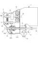
図1は、本発明の4輪駆動用変速機ハウジングを備えた4輪駆動用動力伝達系の斜視図である。図1において、プロペラシャフト6の軸方向のエンジン1側を前方と定義し、左前輪駆動軸4側を左方向、右前輪駆動軸5側を右方向と定義する。また、図面の鉛直上方を上方向と定義する。
[Converter housing mounting position]
FIG. 1 is a perspective view of a four-wheel drive power transmission system provided with a four-wheel drive transmission housing of the present invention. In FIG. 1, the engine 1 side in the axial direction of the
この4輪駆動用動力伝達系は、エンジン1、自動変速機2、トランスファ3から構成される。自動変速機2の右側面の前方にはエンジン1が取り付けられている。自動変速機2の右側面の後方にはトランスファ3が取り付けられている。自動変速機2の左側面開口部からは左前輪駆動軸4が延存されている。トランスファ3の右側面開口部からは右前輪駆動軸5が延存されている。トランスファ3の後面開口部からはプロペラシャフト6が延存されている。
The four-wheel drive power transmission system includes an engine 1, an automatic transmission 2, and a
自動変速機2の外殻である変速機ハウジング200は、コンバータハウジング210と第1ハウジング220と第2ハウジング230とから構成されている。本発明の変速機ハウジングは第1ハウジング220及び第2ハウジング230に相当する。本発明においてコンバータハウジングに変速機ハウジングを取付けるという場合は、特に第1ハウジング220をコンバータハウジング210に取付けることを意味する。
A
コンバータハウジング210左側面のフランジ211と第1ハウジング220右側面のフランジ221とが接合されている。また、第1ハウジング220左側面と第2ハウジング230右側面のフランジ同士が接合されている。コンバータハウジング210右側面には、エンジン1およびトランスファ3が取り付けられている。第2ハウジング230の上面には、変速機ハウジング200を車体に取り付けるためのボルト231、232,233が備えられている。
The
[自動変速機の概略]
図2は、本発明のコンバータハウジング210を備える自動変速機2およびトランスファ3の概略を表す断面図である。自動変速機2の変速機ハウジング200内には変速機構およびトルクコンバータ21が収装されている。変速機構は、発進クラッチを有する前後進切換機構22と、入出力間で無段変速するベルト式無段変速機構23と、ディファレンシャルギア24と、から構成されている。
[Outline of automatic transmission]
FIG. 2 is a cross-sectional view schematically showing the automatic transmission 2 and the
トルクコンバータ21は、エンジン出力軸10および変速機入力軸11と接続される。トルクコンバータ21は、エンジンから出力されたトルクを増幅し、変速機入力軸11を介して前後進切換機構22に伝達する。
Torque
ベルト式無段変速機構23は、前後進切換機構22および変速機入力軸11を介して入力された回転を変速機出力軸12に伝達する。変速機出力軸12の回転は、ディファレンシャルギア24および後輪用駆動軸15に伝達される。
The belt type continuously
ディファレンシャルギア24には左右前輪駆動軸13,14が接続される。ディファレンシャルギア24は、変速機出力軸12から入力された回転を左右前輪駆動軸13,14に伝達する。
Left and right front
後輪用駆動軸15はトランスファ3と接続され、変速機出力軸12から入力される回転をプロペラシャフト6に伝達する。トランスファ3はトランスファハウジングに収装されている。
The rear
[コンバータハウジングの構造]
図3は、コンバータハウジング210をエンジン1側から見た正面図である(図1参照)。
コンバータハウジング210の第1ハウジング220接合側の外周には、第1ハウジング220接合用のフランジ211が設けられている。
[Converter housing structure]
FIG. 3 is a front view of the
A
コンバータハウジング210のエンジン1取り付け側には、トルクコンバータ21収納用の凹部213が設けられており、その中心部に変速機入力軸11用の開口部214が設けられている。凹部213の外周には、コンバータハウジング210をエンジン1に取り付けるためのフランジ212が設けられている。
A
コンバータハウジング210のトランスファ3接合側には、右前輪駆動軸14および後輪用駆動軸15用の開口部215が設けられている。開口部215の周囲には、開口部215を中心として放射状にリブ216aないし216eが設けられている。リブ216aないし216eの遠心方向端にはそれぞれトランスファ3取り付け用のボルト穴217aないし217eが設けられている。
An
ボルト穴217aと217bを結んでリブ216iが、ボルト穴217cと217dを結んでリブ216jが、ボルト穴217dと217eを結んでリブ216kが設けられている。ボルト穴217a、217eとフランジ212を結んでそれぞれリブ216h、216lが設けられている。
A
開口部215の周囲部215a、リブ216aないし216e、リブ216hないし216l、ボルト穴217a周囲部ないし217f周囲部により、トランスファ3取付け用のフランジが構成されている。
The
ボルト穴217fを起点とする略水平方向、略鉛直方向の直線上には、それぞれリブ216f,216gが設けられている。リブ216gはボルト穴217cとボルト穴217fとを結ぶように形成され、同様に、リブ216fはボルト穴217fとボルト穴217i近傍のフランジ212とを結ぶように形成されている。リブ216g、リブ216fは、それぞれ本発明の第1補強リブ、第2補強リブに相当する。
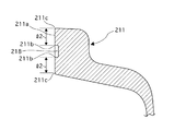
図4は、コンバータハウジング210を第1ハウジング220側から見た正面図である。
フランジ211のフランジ接合面211aは、第1ハウジング220の図外のフランジ接合面221aと接合するために、円滑な平面をなしている。ボルト穴217f(図3参照)の略裏側に位置する部分、すなわちボルト穴217gとボルト穴217hに挟まれる部分のフランジ接合面211a上には、溝218が設けられている。
FIG. 4 is a front view of the
The flange
図5は、コンバータハウジング210をトランスファ3取り付け側から見た斜視図である。フランジ212のエンジン1との接合面212a、およびトランスファ3取り付け用フランジのトランスファ3との接合面は、同一平面上に形成されている。リブ216f,216gは、フランジ211と上記平面との間で、一定の幅を備えるように形成されている。
FIG. 5 is a perspective view of the
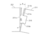
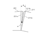
図6は、コンバータハウジング210のトランスファ3との接合部を拡大して示した正面図である。図6において、図面の鉛直上方を上方向と定義し、図面の水平方向を水平方向と定義する。
FIG. 6 is an enlarged front view showing a joint portion of the
リブ216gは、フランジ211およびフランジ212に囲まれる三日月形状の平面内で、リブ216gの長さが最大となるように、かつ、駆動軸用開口部215の周囲部215aおよびリブ216aないしリブ216e、リブ216hないしリブ216lの設置が妨げられない位置に、上下方向に設けられている。
The
具体的には、リブ216cの遠心方向端にあるボルト穴217cから略上方向に伸びる直線とフランジ211との交点部近傍にボルト穴217fが設けられている。そして、ボルト穴217fとボルト穴217cとを結ぶ直線上にリブ216gが設けられている。ボルト穴217f及びボルト穴217cは、フランジ211の内周線に接する位置に形成されている。
Specifically, a
また、ボルト穴217fからフランジ212に向かう略水平方向の直線上、すなわちボルト穴217fとボルト穴217cとを結ぶ直線と略直交する直線上にリブ216fが設けられている。リブ216fのボルト穴217f側と反対側の端は、ボルト穴217i近傍のフランジ212に接合して形成されている。
The
リブ216fとリブ216gは、ボルト穴217f周囲部を頂点として互いに直角に接合し、全体として逆L字形状をなしている。ボルト穴217f周囲部は、本発明のリブ接合点に相当する。
The
図7は、フランジ211の溝218が設けられた部分の正面拡大図である。溝218は、ボルト穴217gとボルト穴217hとを結ぶ軸方向のフランジ接合面211a上に設けられている。具体的には、ボルト穴217gとボルト穴217hとを結ぶ軸方向のフランジ接合面から、ボルト穴217g、217hをそれぞれ囲むリング形状のフランジ接合面211aを除いた範囲のフランジ接合面211a上に、一定の長さと幅をもって設けられている。ボルト穴217g、217h周囲のフランジ接合面211aのリング形状部分の幅をl1と定義する。
FIG. 7 is an enlarged front view of a portion where the
図8は、図6、7に示すA−A断面図である。すなわち、フランジ211の溝218が設けられた部分を、ボルト穴217gとボルト穴217hとを結ぶ軸に対して垂直に切った断面図を示す。溝218は、フランジ接合面211aの略中央位置に設けられている。溝218の端211bからフランジ接合面211aの端211cまでの長さをl2と定義する。l2はl1と同じか、あるいは、l1よりもやや大きくなるように設けられている。
FIG. 8 is a cross-sectional view taken along the line AA shown in FIGS. That is, a cross-sectional view in which a portion provided with the
次に、上記構成に基づくコンバータハウジングの作用を説明する。 Next, the operation of the converter housing based on the above configuration will be described.
[コンバータハウジングに設けられたリブの作用]
図9は、変速機ハウジング200、特にコンバータハウジング210に作用する力を模式的に表した図である。図9において、力の向きを矢印方向で表す。また、コンバータハウジング210のフランジ接合面211aと第1ハウジング220のフランジ接合面221aとが接合する部分をフランジ合わせ部とよぶ。
[Operation of ribs provided on converter housing]
FIG. 9 is a diagram schematically showing the force acting on the
コンバータハウジング210側のフランジ接合面211aには、変速機ハウジング200内部のオイルが外部に漏れることを防ぐため、シール剤が塗布されている。なお、一般にシール剤の種類には、溶剤型液状シール剤と嫌気性シール剤とがあるが、本実施例1では嫌気性シール剤が用いられる。
A sealant is applied to the flange
コンバータハウジング210には、回転軸14,16からトランスファ3に入力されるトルクの反力やトランスファ3の重量等に由来する荷重がかかる。この荷重により、コンバータハウジング210には、プロペラシャフト16軸方向に引張応力ft1および圧縮応力fc1が作用する。同様に、図の鉛直方向に引っ張り応力ft2および圧縮応力fc2が作用する。
The
リブ216f及びリブ216gは、図6に示すように駆動軸用開口部215及び放射状のリブ216aないし216eを囲むように逆L字型に形成されている。すなわち、リブ216fは、応力ft1、fc1が発生する方向に沿って最大の長さを有するように設けられている。同様に、リブ216gは、応力ft2、fc2が発生する方向に沿って最大の長さを有するように設けられている。したがって、リブ216f、リブ216gはこれらの応力ft、fcに対抗してコンバータハウジング210の剛性を強める、という作用を有する。
The
図5に示すように、リブ216f、リブ216gは前輪駆動軸方向に所定の幅を有するように形成されている。一方、リブ216fのボルト穴217f側と反対側の端は、フランジ212に接合している。リブ216gのボルト穴217f側と反対側の端は、ボルト穴217c周囲部と一体に形成されている。したがって、リブ216f、リブ216gのボルト穴217f側と反対側の端がそれぞれフランジ212、ボルト穴217c周囲部により固定されることにより、リブ216f、リブ216g自体の剛性が高められる、という作用を有する。
As shown in FIG. 5, the
[コンバータハウジングのフランジに設けられた溝の作用]
コンバータハウジング210にリブ216f、216gが設けられ、荷重に対抗して剛性が強められている。その結果、図9に示すように、リブ216gには、図面の時計回りに中点Mを中心とする力のモーメントが発生する。よって、リブ216gの上端にはコンバータハウジング210を右前輪駆動軸方向に引っ張る力f1、下端にはコンバータハウジング210を左前輪駆動軸方向に押す力f'1が働く。同時に、力f1の反力f2および力f'1の反力f'2が発生する。
[Operation of groove provided in flange of converter housing]
The
リブ216gは図面の鉛直方向に沿って最大の長さを有するように設けられている。したがって、リブを他の配置にした場合、例えばリブ216gを図面の鉛直方向に沿ってより短くした場合に比べ、リブ216gの鉛直上方端において作用する力のモーメントf1の大きさは最小となる。
The
このとき、コンバータハウジング210を右前輪駆動軸方向に引っ張る力f1およびその反力f2は、リブ216fとリブ216gの交差部分近傍のフランジ合わせ部において発生する。このため、力f1、f2によって、シール剤により密着されていたフランジ合わせ部に隙間が生じ、その部分のシール剤が破断することがある。
At this time, the force f1 that pulls the
一般にフランジ接合面の面積はシール剤強度が十分確保されるように規格により規定されている。しかし、フランジ合わせ部に生じた隙間の大きさが一定以上になると、嫌気性シール剤は連鎖的に変速機ハウジング200内部に向かって破断し、変速機ハウジング200内部と外部とが連通してしまう。これにより、変速機ハウジング200内部のオイルが外部に漏れ出してしまう、といった問題が生じる。
In general, the area of the flange joint surface is defined by the standard so that the sealant strength is sufficiently secured. However, when the size of the gap generated in the flange fitting portion exceeds a certain level, the anaerobic sealant breaks in a chained manner toward the inside of the
このシール剤の連鎖的な破断を防止するため、f1、f2が発生するフランジ合わせ部の(コンバータハウジング210側)フランジ接合面211aに溝218が設けられる(図7、8参照)。
In order to prevent the chain breakage of the sealant, a
図7、8に示すように、ボルト穴217g、217h周囲のフランジ接合面211aには溝218は設けられていない。また、l2はl1と同じか、あるいは、l1よりもやや大きくなるように設けられている。したがって、溝218が設けられている部分のフランジ接合面211aにおいて、シール剤を塗布する糊代は十分に確保されている。言い換えれば、溝218の領域や幅は、ボルト穴217g、217h周囲およびボルト穴217g、217hに挟まれるフランジ接合面211a上に、規格上および技術上定められる必要最低限の面積にシール剤を塗布できる範囲内に設定されている。
As shown in FIGS. 7 and 8, the
図10は、f1、f2により隙間が生じているが、溝218の作用によりシール剤が完全には破断していない状態のフランジ合わせ部の模式図である。図11は、溝218が設けられてない場合のフランジ合わせ部の模式図であり、f1、f2により隙間が生じ、かつ溝218が設けられてないため、シール剤が完全に破断しつつある状態を示したものである。図10,図11ともに、フランジ合わせ部を、ボルト穴217gとボルト穴217hとを結ぶ軸に対して垂直に切った断面図を示す。図10,11において、図の上方向は変速機ハウジング200外側方向、図の下方向は変速機ハウジング200内側方向を示す。図の斜線部分は、シール剤を示す。
FIG. 10 is a schematic view of the flange fitting portion in a state where a gap is generated by f1 and f2, but the sealant is not completely broken by the action of the
図10、図11において、フランジ接合面211aの上端211bとフランジ接合面221aとの間の距離をAとする。図10において、溝218の下端218aとフランジ接合面221aとの間の距離をBとする。また、シール剤の破断が生じる隙間の大きさの限界値をCとする。
10 and 11, A is a distance between the
図10より、AよりBのほうが小さい。また、Cは一定の値をとる。溝218を境界として変速機ハウジング200外側方向のフランジ合わせ部分ではシール剤破断が生じているため、AはCより大きい。一方、溝218を境界として変速機ハウジング200内側方向のフランジ合わせ部分ではシール剤破断が生じていないため、BはCより小さい。
From FIG. 10, B is smaller than A. C takes a constant value. A is larger than C because the sealant fracture occurs at the flange fitting portion in the outer direction of the
したがって、フランジ合わせ部に隙間が生じ、隙間の大きさAが限界値Cを超えた場合であっても、溝218が設けられている場合は、Bの大きさが限界値Cを超えない限り、溝218を境界として変速機ハウジング200内側方向のフランジ合わせ部分におけるシール剤の破断は生じない。すなわち、変速機ハウジング200内部と外部との連通を帰結するシール剤の破断は生じない。
Therefore, even when a gap is generated in the flange fitting portion and the size A of the gap exceeds the limit value C, if the
一方、AだけでなくBの大きさも限界値Cを超えると、変速機ハウジング200内部と外部との連通を帰結するような、溝218を境界として変速機ハウジング200内側方向のフランジ合わせ部分におけるシール剤の破断が生じる。
On the other hand, if not only A but also the size of B exceeds the limit value C, a seal at the flange-fitting portion in the direction toward the inside of the
それに対し、図11に示すように、フランジ接合面211aに溝218が設けられていない場合は、隙間の大きさAが限界値Cを超えるとシール剤の破断が生じ、破断は図の矢印方向に向かって連鎖し、変速機ハウジング200内部と外部との連通が生じる。
On the other hand, as shown in FIG. 11, when the
言い換えると、コンバータハウジング210のフランジ接合面211aに溝218を設けた場合(図10)、溝218を設けない場合(図11)に比べて、シール剤の破断を生じる角αの限界値が大きくなる。したがって、溝218を設けたフランジ接合面211aは、力f1、f2が発生している場合であっても、フランジ接合面211aに塗布されたシール剤の破断を容易に起こさず、変速機ハウジング200内部と外部の連通を容易に起こさない、という作用を有する。
In other words, when the
フランジ合わせ部のうち、力f1、f2によって最も大きな隙間が生じる部位はボルト穴217g、217h間の中点付近である(図7参照)。一方、ボルトにより締結されている両端(ボルト穴217g、217h周囲部)は最も隙間が生じにくい。ここで、ボルト穴217g、217h間の距離は、規格により一定の範囲内に定められている。
Of the flange fitting portion, the site where the largest gap is generated by the forces f1 and f2 is near the midpoint between the bolt holes 217g and 217h (see FIG. 7). On the other hand, the gap is less likely to occur at both ends (bolt
図7に示すように、溝218は、ボルト穴217g、217h間の中点を中心として両端(ボルト穴217g、217h周囲部)方向に向かって一定の長さを有するように設けられている。その長さの範囲内のフランジ合わせ部では、溝218の作用により、上記の距離Bが限界値Cより大きくなることはない。一方、その長さの範囲外のフランジ合わせ部では、ボルトの締結力により、上記の距離Aが限界値Cより大きくなることはない。
As shown in FIG. 7, the
言い換えると、溝218の長さや幅は、変速機ハウジング200内部と外部の連通を生じるようなシール剤の破断を防止できる範囲内であると同時に、フランジ接合面211aにシール剤を塗布できる必要最低限の面積を残す範囲内である。このように、溝218の領域は、シール剤塗布およびシール剤破断防止という2つの要請の調和点として設定されている。
In other words, the length and width of the
[本実施例1の効果]
以上のように、本実施例1では、コンバータハウジング210のトランスファ3取付け部のフランジ面と変速機ハウジング220取付け部のフランジ211面との間に、第1補強リブ216g及び第2補強リブ216fを設け、変速機ハウジング220取付け部のフランジ211の内周線に内接する位置にリブ接合点(ボルト穴217f周囲部)を形成し、第1補強リブ216gを、リブ接合点を起点として鉛直方向に形成し、第2補強リブ216fを、リブ接合点を起点として水平方向に形成し、かつ、第1補強リブ216g及び第2補強リブ216fを、変速機構22〜24からトランスファ3に動力を伝達する駆動軸を囲むように設けた。
[Effect of the first embodiment]
As described above, in the first embodiment, the first reinforcing
これにより、従来のコンバータハウジングの構造を大きく変えることなく、トランスファ3の取り付けに伴う応力の発生に対抗してコンバータハウジング210の剛性を高めることができる。これにより、ギヤ噛合せの悪化、騒音や熱の発生、回転軸受部の偏磨耗、フリクション損失に伴うトルク伝達の悪化等、コンバータハウジング変形に伴う弊害を防止することができる、という効果を有する。
Thereby, the rigidity of
さらに、第1補強リブ216gの両端のうち、リブ接合点の他端をトランスファ3取付け部のフランジ(ボルト穴217c周囲部)と一体に形成し、第2補強リブ216f両端のうち、リブ接合点の他端をエンジン1取付け部のフランジ212に接合して形成した。
Further, of the both ends of the first reinforcing
これにより、リブ216f、リブ216gのボルト穴217f側と反対側の端がそれぞれフランジ212、ボルト穴217c周囲部により固定されることにより、リブ216f、リブ216g自体の剛性が高められる。したがって従来のコンバータハウジングの構造を大きく変えることなく、トランスファ3の取り付けに伴う応力の発生に対抗してコンバータハウジング210の剛性を高めることができる。これにより、ギヤ噛合せの悪化、騒音や熱の発生、回転軸受部の偏磨耗、フリクション損失に伴うトルク伝達の悪化等、コンバータハウジング変形に伴う弊害を防止することができる、という効果を有する。
As a result, the ends of the
また、変速機ハウジング220取り付け部のフランジ211の変速機ハウジング220との接合面211aに、リブ接合点を挟む2つの接合用ボルト穴217g、217hを結ぶ軸線に沿って溝部218を設けた。
Further, a
これにより、リブ216f、リブ216gを設けたことに伴うリブ接合点近傍のフランジ合わせ部分におけるシール性の悪化を防止できる。すなわち、フランジ接合面211aに塗布されたシール剤の破断を容易に起こさず、変速機ハウジング200内部と外部の連通を容易に起こさない。したがって、変速機ハウジング200内部のオイルの外部への漏出を防止できる、という効果を有する。
As a result, it is possible to prevent deterioration of the sealing performance at the flange mating portion in the vicinity of the rib joint due to the provision of the
[他の実施例]
以上、本発明を実施するための最良の形態を、実施例1に基づいて説明してきたが、本発明の具体的な構成は実施例1に限定されるものではなく、発明の要旨を逸脱しない範囲の設計変更等があっても、本発明に含まれる。
[Other Examples]
The best mode for carrying out the present invention has been described based on the first embodiment. However, the specific configuration of the present invention is not limited to the first embodiment and does not depart from the gist of the present invention. Any changes in the design of the range are included in the present invention.
例えば、実施例1においては、溝218をコンバータハウジング210側のフランジ接合面211a上に設ける構成としているが、その替わりに、同様の溝をf1、f2が発生する第1ハウジング220側のフランジ接合面221a上に設ける構成としても良い。この場合も、荷重によるシール剤破断を防止するという実施例1と同等の作用効果が得られる。
For example, in the first embodiment, the
また、実施例1においては、溝218を境界として変速機ハウジング200外側方向および内側方向の両方のフランジ接合面211aにシール剤を塗布する構成としているが、溝218を境界として変速機ハウジング200内側方向のみのフランジ接合面211aにシール剤を塗布する構成としても良い。この場合も、荷重によるシール剤破断防止という実施例1と同等の作用効果が得られる。
In the first embodiment, the sealant is applied to the flange
1 エンジン
2 自動変速機
3 トランスファ
200 変速機ハウジング
210 コンバータハウジング
211,212 フランジ
211a フランジ接合面
215 開口部
216a〜216l リブ
217a〜217i ボルト穴
218 溝
220 第1ハウジング
230 第2ハウジング
DESCRIPTION OF SYMBOLS 1 Engine 2
Claims (2)
トルクコンバータを収装するコンバータハウジングと、
前記変速機構からの出力を前輪側及び後輪側に分岐して伝達する4輪駆動用のトランスファを収装するトランスファハウジングと、
を備えた4輪駆動用変速機ハウジングにおいて、
前記コンバータハウジングには、一方の側面にエンジン取付け部とトランスファ取付け部とが、他方の側面に前記変速機ハウジングを取付ける変速機ハウジング取付け部が、一体形成され、
前記トランスファ取付け部のフランジ面と前記変速機ハウジング取付け部のフランジ面との間に、第1補強リブ及び第2補強リブを設け、
前記変速機ハウジング取付け部のフランジの内周線に内接する位置にリブ接合点を形成し、
前記第1補強リブは、一端側の前記リブ接合点を起点として鉛直方向に延在し、他端側の前記トランスファ取付け部のフランジと一体に形成し、
前記第2補強リブは、一端側の前記リブ接合点を起点として水平方向に延在し、他端側の前記エンジン取付け部のフランジと一体に形成し、
かつ、前記第1補強リブ及び前記第2補強リブを、前記変速機構から前記トランスファに動力を伝達する駆動軸を囲むように設けたこと
を特徴とする4輪駆動用変速機ハウジング。 A transmission housing that houses a transmission mechanism for shifting and outputting engine output rotation;
A converter housing for housing the torque converter;
A transfer housing that houses a transfer for a four-wheel drive that branches and transmits the output from the speed change mechanism to the front wheel side and the rear wheel side;
In a four-wheel drive transmission housing comprising:
The converter housing is integrally formed with an engine mounting portion and a transfer mounting portion on one side surface, and a transmission housing mounting portion for mounting the transmission housing on the other side surface,
A first reinforcing rib and a second reinforcing rib are provided between the flange surface of the transfer mounting portion and the flange surface of the transmission housing mounting portion,
Forming a rib joint at a position inscribed in the inner peripheral line of the flange of the transmission housing mounting portion;
The first reinforcing rib extends in the vertical direction from the rib joint on one end side, and is integrally formed with the flange of the transfer mounting portion on the other end side ,
The second reinforcing rib extends in a horizontal direction starting from the rib joining point on one end side, and is formed integrally with a flange of the engine mounting portion on the other end side ,
The four-wheel drive transmission housing is characterized in that the first reinforcing rib and the second reinforcing rib are provided so as to surround a drive shaft for transmitting power from the transmission mechanism to the transfer.
を特徴とする請求項1に記載の4輪駆動用変速機ハウジング。 The groove portion is provided on the joint surface of the flange of the transmission housing mounting portion with the transmission housing along an axis connecting two joint bolt holes sandwiching the rib joint point. A transmission housing for a four-wheel drive as described.
Priority Applications (2)
| Application Number | Priority Date | Filing Date | Title |
|---|---|---|---|
| JP2005299857A JP4627240B2 (en) | 2005-10-14 | 2005-10-14 | 4-wheel drive transmission housing structure |
| US11/580,056 US7658128B2 (en) | 2005-10-14 | 2006-10-13 | Transmission housing structure for four wheel drive system |
Applications Claiming Priority (1)
| Application Number | Priority Date | Filing Date | Title |
|---|---|---|---|
| JP2005299857A JP4627240B2 (en) | 2005-10-14 | 2005-10-14 | 4-wheel drive transmission housing structure |
Publications (2)
| Publication Number | Publication Date |
|---|---|
| JP2007107630A JP2007107630A (en) | 2007-04-26 |
| JP4627240B2 true JP4627240B2 (en) | 2011-02-09 |
Family
ID=38033649
Family Applications (1)
| Application Number | Title | Priority Date | Filing Date |
|---|---|---|---|
| JP2005299857A Active JP4627240B2 (en) | 2005-10-14 | 2005-10-14 | 4-wheel drive transmission housing structure |
Country Status (2)
| Country | Link |
|---|---|
| US (1) | US7658128B2 (en) |
| JP (1) | JP4627240B2 (en) |
Families Citing this family (30)
| Publication number | Priority date | Publication date | Assignee | Title |
|---|---|---|---|---|
| US8056333B1 (en) | 2007-08-01 | 2011-11-15 | Hydro-Gear Limited Partnership | Pump and engine configuration |
| EP2065619A1 (en) * | 2007-11-28 | 2009-06-03 | Kwang Yang Motor Co., Ltd. | Vehicle transmission |
| US8925311B1 (en) | 2009-07-24 | 2015-01-06 | Hydro-Gear Limited Partnership | Transmission and engine configuration |
| GB2489938B8 (en) * | 2011-04-08 | 2017-06-14 | Vitec Group Plc | A drive train apparatus |
| CN202946651U (en) * | 2012-09-27 | 2013-05-22 | 陕西法士特齿轮有限责任公司 | Reverse gear intermediate shaft supporting structure of transmission |
| KR102061164B1 (en) * | 2013-02-28 | 2020-01-02 | 삼성전자주식회사 | Refrigerator Having Apparatus For Producing Carbonated Water |
| JP6248770B2 (en) * | 2014-04-11 | 2017-12-20 | スズキ株式会社 | Power transmission device |
| JP2016070442A (en) * | 2014-09-30 | 2016-05-09 | ダイハツ工業株式会社 | Transmission case |
| JP6474296B2 (en) | 2015-03-26 | 2019-02-27 | ジヤトコ株式会社 | Transmission case for vehicle transmission |
| CN106740050B (en) * | 2015-11-23 | 2021-11-23 | 舍弗勒技术股份两合公司 | Hybrid module assembly and shell thereof |
| CN105864402A (en) * | 2016-06-21 | 2016-08-17 | 肇庆高新区凯盈顺汽车设计有限公司 | Transmission housing |
| US10295044B2 (en) | 2016-10-12 | 2019-05-21 | Ford Global Technologies, Llc | Brace for powerplant |
| JP7013644B2 (en) * | 2016-11-14 | 2022-02-01 | スズキ株式会社 | transmission |
| USD866625S1 (en) * | 2017-02-28 | 2019-11-12 | Eaton Cummins Automated Transmission Technologies, Llc | Transmission housing |
| USD933712S1 (en) | 2017-02-28 | 2021-10-19 | Eaton Cummins Automated Transmission Technologies, Llc | Clutch housing |
| USD914073S1 (en) * | 2017-02-28 | 2021-03-23 | Eaton Cummins Automated Transmission Technologies, Llc | Transmission rear housing |
| CN107830157B (en) * | 2017-10-30 | 2020-08-14 | 兴化市雅兰机械制造有限公司 | Gear assembling gear box |
| WO2020157861A1 (en) * | 2019-01-30 | 2020-08-06 | 株式会社ショーワ | Steering device |
| JP7322497B2 (en) * | 2019-05-14 | 2023-08-08 | スズキ株式会社 | Vehicle drive system |
| USD898089S1 (en) * | 2019-06-03 | 2020-10-06 | Warn Industries, Inc. | Transmission end housing |
| USD966371S1 (en) | 2019-09-13 | 2022-10-11 | Eaton Cummins Automated Transmission Technologies, Llc | Transmission intermediate plate |
| USD930725S1 (en) | 2019-09-13 | 2021-09-14 | Eaton Cummins Automated Transmission Technologies, Llc | Transmission main housing |
| USD915485S1 (en) | 2019-09-13 | 2021-04-06 | Eaton Cummins Automated Transmission Technologies, Llc | Transmission rear housing |
| CN111075910A (en) * | 2020-01-09 | 2020-04-28 | 精进电动科技(菏泽)有限公司 | Reduction case structure |
| US11535057B2 (en) | 2020-09-09 | 2022-12-27 | Mahindra N.A. Tech Center | Axle assembly with sealed wheel end bearings and sealed pinion input bearings |
| US11225107B1 (en) | 2020-09-09 | 2022-01-18 | Mahindra N.A. Tech Center | Axle carrier housing with reinforcement structure |
| US11655891B2 (en) | 2020-09-09 | 2023-05-23 | Mahindra N.A. Tech Center | Method of machining an axle carrier housing |
| US11648745B2 (en) | 2020-09-09 | 2023-05-16 | Mahindra N.A. Tech Center | Modular tooling for axle housing and manufacturing process |
| EP4001699A1 (en) * | 2020-11-17 | 2022-05-25 | Ratier-Figeac SAS | Gearbox assembly |
| CN114508581B (en) * | 2022-02-22 | 2024-01-09 | 一汽解放汽车有限公司 | Transmission shell and transmission |
Citations (8)
| Publication number | Priority date | Publication date | Assignee | Title |
|---|---|---|---|---|
| JPH01133569U (en) * | 1988-03-08 | 1989-09-12 | ||
| JPH0392545A (en) * | 1989-09-05 | 1991-04-17 | Nissan Motor Co Ltd | Connecting structure between cylinder block and transmission side housing |
| JPH0558178A (en) * | 1991-09-02 | 1993-03-09 | Jatco Corp | Horizontal transmission for midship four-wheel drive |
| JPH10272944A (en) * | 1997-03-31 | 1998-10-13 | Mazda Motor Corp | Transfer structure of four-wheel drive vehicle |
| JPH10299870A (en) * | 1997-04-25 | 1998-11-13 | Nissan Motor Co Ltd | Transmission case joining structure |
| JP2001271915A (en) * | 2000-03-24 | 2001-10-05 | Tcm Corp | Industrial vehicle |
| JP2002327833A (en) * | 2001-04-27 | 2002-11-15 | Fuji Heavy Ind Ltd | Lubricant feeder for transmission |
| JP2003214530A (en) * | 2002-01-21 | 2003-07-30 | Nissan Motor Co Ltd | Breather structure of transfer |
Family Cites Families (12)
| Publication number | Priority date | Publication date | Assignee | Title |
|---|---|---|---|---|
| EP0201931B1 (en) * | 1985-05-15 | 1989-01-18 | Toyota Jidosha Kabushiki Kaisha | Power transmission for automotive vehicle |
| KR920003985B1 (en) * | 1987-09-01 | 1992-05-21 | 마쯔다 가부시기가이샤 | Four-wheel drive vehicle |
| JPH083348B2 (en) * | 1988-10-07 | 1996-01-17 | 日産自動車株式会社 | Automatic transaxle |
| JP2698144B2 (en) * | 1989-01-31 | 1998-01-19 | マツダ株式会社 | Car transmission case |
| US4995971A (en) * | 1989-08-07 | 1991-02-26 | Ford Motor Company | Dual purpose automatic transmission oil pan |
| JP3637111B2 (en) * | 1995-08-11 | 2005-04-13 | 富士重工業株式会社 | Transmission fastening structure of power unit for vehicle |
| JP3627337B2 (en) * | 1995-12-27 | 2005-03-09 | アイシン・エィ・ダブリュ株式会社 | Electric vehicle drive |
| US6158303A (en) * | 1997-03-21 | 2000-12-12 | Mazda Motor Corporation | Transfer case for four wheel drive vehicle |
| JP2001146956A (en) | 1999-11-19 | 2001-05-29 | Suzuki Motor Corp | Differential device of automobile |
| DE10047233A1 (en) * | 2000-09-23 | 2002-04-11 | Zahnradfabrik Friedrichshafen | machine housing |
| JP4040486B2 (en) * | 2003-02-10 | 2008-01-30 | トヨタ自動車株式会社 | Foamed resin oil pan and method for producing the same |
| US7493999B2 (en) * | 2004-03-22 | 2009-02-24 | General Motors Corporation | Hybrid electro-mechanical transmission park system and method of assembly |
-
2005
- 2005-10-14 JP JP2005299857A patent/JP4627240B2/en active Active
-
2006
- 2006-10-13 US US11/580,056 patent/US7658128B2/en active Active
Patent Citations (8)
| Publication number | Priority date | Publication date | Assignee | Title |
|---|---|---|---|---|
| JPH01133569U (en) * | 1988-03-08 | 1989-09-12 | ||
| JPH0392545A (en) * | 1989-09-05 | 1991-04-17 | Nissan Motor Co Ltd | Connecting structure between cylinder block and transmission side housing |
| JPH0558178A (en) * | 1991-09-02 | 1993-03-09 | Jatco Corp | Horizontal transmission for midship four-wheel drive |
| JPH10272944A (en) * | 1997-03-31 | 1998-10-13 | Mazda Motor Corp | Transfer structure of four-wheel drive vehicle |
| JPH10299870A (en) * | 1997-04-25 | 1998-11-13 | Nissan Motor Co Ltd | Transmission case joining structure |
| JP2001271915A (en) * | 2000-03-24 | 2001-10-05 | Tcm Corp | Industrial vehicle |
| JP2002327833A (en) * | 2001-04-27 | 2002-11-15 | Fuji Heavy Ind Ltd | Lubricant feeder for transmission |
| JP2003214530A (en) * | 2002-01-21 | 2003-07-30 | Nissan Motor Co Ltd | Breather structure of transfer |
Also Published As
| Publication number | Publication date |
|---|---|
| US7658128B2 (en) | 2010-02-09 |
| US20070155572A1 (en) | 2007-07-05 |
| JP2007107630A (en) | 2007-04-26 |
Similar Documents
| Publication | Publication Date | Title |
|---|---|---|
| JP4627240B2 (en) | 4-wheel drive transmission housing structure | |
| US8955658B2 (en) | Vehicle power transmission device | |
| JP5303970B2 (en) | Carrier assembly | |
| EP2644942A1 (en) | Vehicular power transmission device | |
| US8839922B2 (en) | Vehicle power transmission device | |
| EP2644944B1 (en) | Vehicular power transmission device | |
| JP5186977B2 (en) | Transmission case | |
| CN114135653A (en) | Power transmission device | |
| KR101833122B1 (en) | Transmission case of transmission device for vehicle | |
| JP6135450B2 (en) | Differential device | |
| JP6509084B2 (en) | Transmission case of transmission for vehicle | |
| JP5905693B2 (en) | Fluid transmission device for vehicles | |
| JP5866951B2 (en) | Axle connection structure | |
| JP5613419B2 (en) | Power transmission device | |
| JP6624953B2 (en) | Oil pump drive structure | |
| JP6328184B2 (en) | Transmission unit | |
| JP2008121738A (en) | Flange structure to which rotation driving force transmitting member is fixed | |
| JP7082035B2 (en) | Differential device | |
| JP2006199222A (en) | Power transmitting device for vehicle | |
| JP5926575B2 (en) | Seal body, apparatus and method | |
| CN112654804A (en) | Housing component of power transmission device | |
| JP2015086899A (en) | Fluid-type transmission device | |
| KR200166655Y1 (en) | Torque converter for a vehicle | |
| JP4109622B2 (en) | Bearing structure of input shaft | |
| JP2019100484A (en) | Torsional damper |
Legal Events
| Date | Code | Title | Description |
|---|---|---|---|
| A621 | Written request for application examination |
Free format text: JAPANESE INTERMEDIATE CODE: A621 Effective date: 20070808 |
|
| A977 | Report on retrieval |
Free format text: JAPANESE INTERMEDIATE CODE: A971007 Effective date: 20081211 |
|
| A131 | Notification of reasons for refusal |
Free format text: JAPANESE INTERMEDIATE CODE: A131 Effective date: 20090310 |
|
| A521 | Request for written amendment filed |
Free format text: JAPANESE INTERMEDIATE CODE: A523 Effective date: 20090422 |
|
| A131 | Notification of reasons for refusal |
Free format text: JAPANESE INTERMEDIATE CODE: A131 Effective date: 20100216 |
|
| A521 | Request for written amendment filed |
Free format text: JAPANESE INTERMEDIATE CODE: A523 Effective date: 20100414 |
|
| TRDD | Decision of grant or rejection written | ||
| A01 | Written decision to grant a patent or to grant a registration (utility model) |
Free format text: JAPANESE INTERMEDIATE CODE: A01 Effective date: 20101102 |
|
| A01 | Written decision to grant a patent or to grant a registration (utility model) |
Free format text: JAPANESE INTERMEDIATE CODE: A01 |
|
| A61 | First payment of annual fees (during grant procedure) |
Free format text: JAPANESE INTERMEDIATE CODE: A61 Effective date: 20101104 |
|
| FPAY | Renewal fee payment (event date is renewal date of database) |
Free format text: PAYMENT UNTIL: 20131119 Year of fee payment: 3 |
|
| R150 | Certificate of patent or registration of utility model |
Ref document number: 4627240 Country of ref document: JP Free format text: JAPANESE INTERMEDIATE CODE: R150 Free format text: JAPANESE INTERMEDIATE CODE: R150 |
|
| FPAY | Renewal fee payment (event date is renewal date of database) |
Free format text: PAYMENT UNTIL: 20131119 Year of fee payment: 3 |
|
| FPAY | Renewal fee payment (event date is renewal date of database) |
Free format text: PAYMENT UNTIL: 20141119 Year of fee payment: 4 |
|
| S111 | Request for change of ownership or part of ownership |
Free format text: JAPANESE INTERMEDIATE CODE: R313114 |
|
| R350 | Written notification of registration of transfer |
Free format text: JAPANESE INTERMEDIATE CODE: R350 |