JP4624342B2 - Cartridge and method for preparing a beverage - Google Patents
Cartridge and method for preparing a beverage Download PDFInfo
- Publication number
- JP4624342B2 JP4624342B2 JP2006500240A JP2006500240A JP4624342B2 JP 4624342 B2 JP4624342 B2 JP 4624342B2 JP 2006500240 A JP2006500240 A JP 2006500240A JP 2006500240 A JP2006500240 A JP 2006500240A JP 4624342 B2 JP4624342 B2 JP 4624342B2
- Authority
- JP
- Japan
- Prior art keywords
- cartridge
- beverage
- storage chamber
- filter
- outlet
- Prior art date
- Legal status (The legal status is an assumption and is not a legal conclusion. Google has not performed a legal analysis and makes no representation as to the accuracy of the status listed.)
- Expired - Fee Related
Links
Images


Classifications
-
- B—PERFORMING OPERATIONS; TRANSPORTING
- B65—CONVEYING; PACKING; STORING; HANDLING THIN OR FILAMENTARY MATERIAL
- B65D—CONTAINERS FOR STORAGE OR TRANSPORT OF ARTICLES OR MATERIALS, e.g. BAGS, BARRELS, BOTTLES, BOXES, CANS, CARTONS, CRATES, DRUMS, JARS, TANKS, HOPPERS, FORWARDING CONTAINERS; ACCESSORIES, CLOSURES, OR FITTINGS THEREFOR; PACKAGING ELEMENTS; PACKAGES
- B65D85/00—Containers, packaging elements or packages, specially adapted for particular articles or materials
- B65D85/70—Containers, packaging elements or packages, specially adapted for particular articles or materials for materials not otherwise provided for
- B65D85/804—Disposable containers or packages with contents which are mixed, infused or dissolved in situ, i.e. without having been previously removed from the package
- B65D85/8043—Packages adapted to allow liquid to pass through the contents
-
- A—HUMAN NECESSITIES
- A47—FURNITURE; DOMESTIC ARTICLES OR APPLIANCES; COFFEE MILLS; SPICE MILLS; SUCTION CLEANERS IN GENERAL
- A47J—KITCHEN EQUIPMENT; COFFEE MILLS; SPICE MILLS; APPARATUS FOR MAKING BEVERAGES
- A47J31/00—Apparatus for making beverages
- A47J31/24—Coffee-making apparatus in which hot water is passed through the filter under pressure, i.e. in which the coffee grounds are extracted under pressure
- A47J31/34—Coffee-making apparatus in which hot water is passed through the filter under pressure, i.e. in which the coffee grounds are extracted under pressure with hot water under liquid pressure
- A47J31/36—Coffee-making apparatus in which hot water is passed through the filter under pressure, i.e. in which the coffee grounds are extracted under pressure with hot water under liquid pressure with mechanical pressure-producing means
- A47J31/3666—Coffee-making apparatus in which hot water is passed through the filter under pressure, i.e. in which the coffee grounds are extracted under pressure with hot water under liquid pressure with mechanical pressure-producing means whereby the loading of the brewing chamber with the brewing material is performed by the user
- A47J31/3676—Cartridges being employed
- A47J31/369—Impermeable cartridges being employed
- A47J31/3695—Cartridge perforating means for creating the hot water inlet
-
- A—HUMAN NECESSITIES
- A47—FURNITURE; DOMESTIC ARTICLES OR APPLIANCES; COFFEE MILLS; SPICE MILLS; SUCTION CLEANERS IN GENERAL
- A47J—KITCHEN EQUIPMENT; COFFEE MILLS; SPICE MILLS; APPARATUS FOR MAKING BEVERAGES
- A47J31/00—Apparatus for making beverages
- A47J31/06—Filters or strainers for coffee or tea makers ; Holders therefor
- A47J31/0642—Filters or strainers for coffee or tea makers ; Holders therefor specially adapted to cooperate with a cartridge, e.g. having grooves or protrusions to separate cartridge from the bottom of the brewing chamber
-
- A—HUMAN NECESSITIES
- A47—FURNITURE; DOMESTIC ARTICLES OR APPLIANCES; COFFEE MILLS; SPICE MILLS; SUCTION CLEANERS IN GENERAL
- A47J—KITCHEN EQUIPMENT; COFFEE MILLS; SPICE MILLS; APPARATUS FOR MAKING BEVERAGES
- A47J31/00—Apparatus for making beverages
- A47J31/06—Filters or strainers for coffee or tea makers ; Holders therefor
- A47J31/0657—Filters or strainers for coffee or tea makers ; Holders therefor for brewing coffee under pressure, e.g. for espresso machines
- A47J31/0668—Filters or strainers for coffee or tea makers ; Holders therefor for brewing coffee under pressure, e.g. for espresso machines specially adapted for cartridges
- A47J31/0673—Means to perforate the cartridge for creating the beverage outlet
-
- A—HUMAN NECESSITIES
- A47—FURNITURE; DOMESTIC ARTICLES OR APPLIANCES; COFFEE MILLS; SPICE MILLS; SUCTION CLEANERS IN GENERAL
- A47J—KITCHEN EQUIPMENT; COFFEE MILLS; SPICE MILLS; APPARATUS FOR MAKING BEVERAGES
- A47J31/00—Apparatus for making beverages
- A47J31/44—Parts or details or accessories of beverage-making apparatus
- A47J31/4403—Constructional details
- A47J31/4407—Lids, covers or knobs
-
- A—HUMAN NECESSITIES
- A47—FURNITURE; DOMESTIC ARTICLES OR APPLIANCES; COFFEE MILLS; SPICE MILLS; SUCTION CLEANERS IN GENERAL
- A47J—KITCHEN EQUIPMENT; COFFEE MILLS; SPICE MILLS; APPARATUS FOR MAKING BEVERAGES
- A47J31/00—Apparatus for making beverages
- A47J31/44—Parts or details or accessories of beverage-making apparatus
- A47J31/4492—Means to read code provided on ingredient pod or cartridge
-
- A—HUMAN NECESSITIES
- A47—FURNITURE; DOMESTIC ARTICLES OR APPLIANCES; COFFEE MILLS; SPICE MILLS; SUCTION CLEANERS IN GENERAL
- A47J—KITCHEN EQUIPMENT; COFFEE MILLS; SPICE MILLS; APPARATUS FOR MAKING BEVERAGES
- A47J31/00—Apparatus for making beverages
- A47J31/44—Parts or details or accessories of beverage-making apparatus
- A47J31/54—Water boiling vessels in beverage making machines
- A47J31/56—Water boiling vessels in beverage making machines having water-level controls; having temperature controls
-
- B—PERFORMING OPERATIONS; TRANSPORTING
- B67—OPENING, CLOSING OR CLEANING BOTTLES, JARS OR SIMILAR CONTAINERS; LIQUID HANDLING
- B67D—DISPENSING, DELIVERING OR TRANSFERRING LIQUIDS, NOT OTHERWISE PROVIDED FOR
- B67D1/00—Apparatus or devices for dispensing beverages on draught
- B67D1/08—Details
- B67D1/0801—Details of beverage containers, e.g. casks, kegs
- B67D2001/0812—Bottles, cartridges or similar containers
Description
本発明は、飲料を調製するためのカートリッジシステムに関し、特に、実質的に空気および水分に対して不透過性である材料で形成され、飲料の調製用に1種類または複数種類の原料を含有するシール済みカートリッジに関する。カートリッジシステムを製造する方法も開示される。 The present invention relates to a cartridge system for preparing a beverage, in particular formed of a material that is substantially impermeable to air and moisture and contains one or more ingredients for the preparation of a beverage. It relates to a sealed cartridge. A method of manufacturing a cartridge system is also disclosed.
空気に対して不透過性である個包装内に飲料調製原料をシールすることが、これまで提案されてきた。例えば、挽いたコーヒーを圧縮して含有するカートリッジやカプセルは、一般に「エスプレッソ」機械と呼ばれる特定のコーヒー調製機械で使用するものとして知られている。こうした調製機械を用いたコーヒーの製造では、コーヒーカートリッジが煎出チャンバ内に配置され、湯がこのカートリッジを比較的高い圧力で通過することにより、挽かれたコーヒーから薫り高いコーヒー成分が抽出されて、コーヒー飲料を生成する。通常、こうした機械は、6×10⁵Paを超える圧力で動作する。このタイプの調製機械は、これに含まれる水ポンプおよびシールなどのコンポーネンツが高圧に耐えられるものでなければならないため、今まで比較的高価であった。 It has been proposed to seal beverage preparation ingredients in individual packages that are impermeable to air. For example, cartridges and capsules containing compressed ground coffee are known for use in certain coffee brewing machines commonly referred to as “espresso” machines. In the production of coffee using such a brewing machine, a coffee cartridge is placed in the brewing chamber, and hot water passes through the cartridge at a relatively high pressure to extract ground coffee components from the ground coffee. Produce coffee drinks. Usually such machines operate at pressures in excess of 6 × 10 5 Pa. This type of preparation machine has been relatively expensive until now because the components, such as water pumps and seals, it must be able to withstand high pressures.
従来技術には、概して0.7から2.0×10⁵Paで動作する飲料調製用カートリッジが記載されている(例えば、特許文献1参照)。しかし、このカートリッジは、商業または工業市場用飲料調製機内で使用する設計となっており、比較的高価である上、多くのタイプの飲料を生成することができない。したがって、システムのカートリッジおよび飲料調製機が、特に、価格、性能および信頼性の面で家庭向け市場に適したものとなっている飲料調製用システムが必要である。また、操作が単純であり操作の信頼性が高く、広範なタイプの飲料を比較的低圧で生成可能である、こうしたシステムのための飲料調製機も必要である。 The prior art describes beverage preparation cartridges that generally operate at 0.7 to 2.0 × 10 5 Pa (see, for example, Patent Document 1). However, this cartridge is designed for use in beverage brewers for commercial or industrial markets, is relatively expensive and cannot produce many types of beverages. Accordingly, there is a need for a beverage preparation system in which the system cartridge and beverage preparation machine are particularly suitable for the home market in terms of price, performance and reliability. There is also a need for a beverage preparation machine for such a system that is simple to operate, reliable in operation, and capable of producing a wide variety of beverages at relatively low pressures.
したがって、本発明は、1種類または複数種類の飲料原料を含有し、実質的に空気および水分に対して不透過性である材料で形成されたカートリッジであって、前記1種類または複数種類の飲料原料を含有する貯蔵チャンバ(134)を含み、前記貯蔵チャンバの幅に対する前記貯蔵チャンバの高さのアスペクト比が0.10と0.43との間であることを特徴とするカートリッジを提供する。 Accordingly, the present invention is a cartridge formed of a material that contains one or more types of beverage ingredients and is substantially impermeable to air and moisture, wherein the one or more types of beverages There is provided a cartridge comprising a storage chamber (134) containing a raw material, wherein the aspect ratio of the height of the storage chamber to the width of the storage chamber is between 0.10 and 0.43.
これらのアスペクト比を有するカートリッジを使用することによって、低い圧力における効率的な調製が可能になることが確認されている。 It has been determined that the use of cartridges having these aspect ratios allows for efficient preparation at low pressures.
特に、前記アスペクト比は、飲料原料の不均一または薄い抽出、希釈、または分解に繋がるような、カートリッジを通じた不均一または不適切な水の流れを招きうる望まれない高い背圧の確立(build up)を妨げることが確認されている。高い背圧を妨げることにより、低圧のシステムと共にカートリッジを使用することが可能になり、そのような低圧システムは高圧のシステムよりも安価であり従って家庭向けのマーケットにより適している。 In particular, the aspect ratio establishes an undesirably high back pressure that can lead to uneven or improper water flow through the cartridge, leading to uneven or thin extraction, dilution, or degradation of the beverage ingredients. up) has been confirmed. Preventing high back pressure allows the cartridge to be used with low pressure systems, which are less expensive than high pressure systems and are therefore more suitable for the home market.
さらに、これらのアスペクト比の使用は、使用の際のカートリッジが水平に配置される場合に、特に有利な効果を有する。貯蔵チャンバの幅と高さを慎重に選択することにより、プロセスの一貫性を改善するために内向きおよび上向きの両方の流れの要素を有する貯蔵チャンバ内における流れの改善が可能になる。 Furthermore, the use of these aspect ratios has a particularly advantageous effect when the cartridge in use is arranged horizontally. Careful selection of the width and height of the storage chamber allows for improved flow in the storage chamber with both inward and upward flow elements to improve process consistency.
好ましくは、貯蔵チャンバの幅に対する貯蔵チャンバの高さのアスペクト比は、0.21と0.28との間である。更に好ましくは、アスペクト比は概ね0.25である。 Preferably, the aspect ratio of the height of the storage chamber to the width of the storage chamber is between 0.21 and 0.28. More preferably, the aspect ratio is approximately 0.25.
好ましくは、カートリッジはディスク形である。 Preferably, the cartridge is disk shaped.
もしくは、カートリッジはディスク型でなく、且つ、前記アスペクト比は最大距離に対する最大高さの比率として測定される。 Alternatively, the cartridge is not disk-shaped and the aspect ratio is measured as the ratio of the maximum height to the maximum distance.
カートリッジは、該貯蔵チャンバに放射状に導入される1つまたはそれ以上の入口を含んでもよい。 The cartridge may include one or more inlets that are introduced radially into the storage chamber.
前記1つまたはそれ以上の入口は、水性媒体の流れを内向きに前記貯蔵チャンバに導くように、前記カートリッジの周縁に、またはその近傍に配置されてもよい。 The one or more inlets may be located at or near the periphery of the cartridge to direct the flow of aqueous medium inward to the storage chamber.
カートリッジは、貯蔵チャンバとカートリッジの下面の少なくとも一部との間に配置されたフィルタと、前記フィルタとカートリッジの頂部との間に形成された1つまたはそれ以上の通路とを更に含み、該1つまたはそれ以上の通路は前記カートリッジの出口に連通し、これによって、前記1つまたはそれ以上の入口を出口に連結している飲料の流路が上向きに前記フィルタを通じて前記1つまたはそれ以上の通路内へと流通することとしてもよい。 The cartridge further includes a filter disposed between the storage chamber and at least a portion of the lower surface of the cartridge, and one or more passages formed between the filter and the top of the cartridge. One or more passages communicate with the outlet of the cartridge, whereby a beverage flow path connecting the one or more inlets to the outlet is directed upwardly through the filter. It is good also as distributing in a passage.
飲料原料は、焙煎および挽き作業を施したコーヒーであってもよい。 The beverage ingredient may be coffee that has been roasted and ground.
クレームされたアスペクト比の使用は、抽出が行われる焙煎および挽き作業を施したコーヒーなどのような原料について特に有利である。抽出中におけるチャンバー内の正確な圧力と流れのパターンは、調製される飲料の品質と一貫性のために大変重要である。 The use of the claimed aspect ratio is particularly advantageous for ingredients such as roasted and ground operations such as coffee where extraction is performed. The exact pressure and flow pattern in the chamber during extraction is very important for the quality and consistency of the beverage being prepared.
本発明はまた、貯蔵チャンバ内に1種類または複数種類の飲料原料を含有するカートリッジから飲料を供給する方法を提供する。この方法は、前記1種類または複数種類の飲料原料から飲料を形成するように、前記カートリッジに水性媒体を通過させるステップと、前記飲料を入れ物内に供給するステップとを含み、前記カートリッジは、前記貯蔵チャンバの幅に対する前記貯蔵チャンバの高さのアスペクト比が0.10と0.43との間であり、前記水性媒体は0.1から2.0バール(10から200KPa)の圧力でカートリッジを通過させられることを特徴とする。 The present invention also provides a method of dispensing a beverage from a cartridge containing one or more beverage ingredients in a storage chamber. The method includes passing an aqueous medium through the cartridge to form a beverage from the one or more types of beverage ingredients and supplying the beverage into a container, the cartridge comprising the cartridge The aspect ratio of the height of the storage chamber to the width of the storage chamber is between 0.10 and 0.43, and the aqueous medium is loaded into the cartridge at a pressure of 0.1 to 2.0 bar (10 to 200 KPa). It is made to pass through.
好ましくは、貯蔵チャンバの幅に対する貯蔵チャンバの高さのアスペクト比は0.21と0.28との間である。 Preferably, the aspect ratio of the height of the storage chamber to the width of the storage chamber is between 0.21 and 0.28.
本発明は更に、2.0から4.0バールの圧力の水性媒体と共に使用され、1種類または複数種類の飲料原料を含有し、且つ実質的に空気および水分に対して不透過性である材料で形成され、前記1種類または複数種類の飲料原料を含有する貯蔵チャンバを含んだカートリッジを提供する。このカートリッジは、貯蔵チャンバの幅に対する前記貯蔵チャンバの高さのアスペクト比が0.10と0.43との間である。 The present invention is further used with an aqueous medium at a pressure of 2.0 to 4.0 bar and contains one or more beverage ingredients and is substantially impermeable to air and moisture. And a cartridge including a storage chamber containing the one or more types of beverage ingredients. The cartridge has an aspect ratio of the height of the storage chamber to the width of the storage chamber between 0.10 and 0.43.
本発明はまた、貯蔵チャンバ内に1種類または複数種類の飲料原料を含有するカートリッジから飲料を供給する方法であって、前記1種類または複数種類の飲料原料から飲料を形成するように、前記カートリッジに水性媒体を通過させるステップと、前記飲料を入れ物内に供給するステップとを含み、前記カートリッジは、前記貯蔵チャンバの幅に対する前記貯蔵チャンバの高さのアスペクト比が0.42と0.68との間であり、前記水性媒体は2.0から4.0バールの圧力でカートリッジを通過させられることを特徴とする方法を提供する。 The present invention is also a method for supplying a beverage from a cartridge containing one or more types of beverage ingredients in a storage chamber, wherein the cartridge is formed from the one or more types of beverage ingredients. Passing the aqueous medium through the container and supplying the beverage into a container, wherein the cartridge has an aspect ratio of the height of the storage chamber to the width of the storage chamber of 0.42 and 0.68. Wherein the aqueous medium is passed through the cartridge at a pressure of 2.0 to 4.0 bar.
本発明のカートリッジは、飲料製品の構成のために好適な1種類または複数種類の原料を含有する。飲料製品は、例えば、コーヒー、茶、チョコレートまたはミルクを含む日常の(daily-based)飲料であってよい。飲料原料は粉状化され、挽き作業を施され、葉を元にし(leaf-based)、または液状であってよい。飲料原料は不溶性または可溶性のいずれであってもよい。焙煎され挽き作業を施されたコーヒー、葉茶(leaf tea)、粉状化された固形ココア(cocoa solids)およびスープ、液状のミルクを基にした(milk-based)飲料および濃縮されたフルーツジュースが例に含まれる。 The cartridge of the present invention contains one or more ingredients suitable for the construction of a beverage product. The beverage product may be a daily-based beverage including, for example, coffee, tea, chocolate or milk. The beverage ingredients may be pulverized, ground, leaf-based, or liquid. The beverage ingredient may be insoluble or soluble. Roasted and ground coffee, leaf tea, pulverized cocoa solids and soup, milk-based beverages and concentrated fruits Juice is included in the example.
以下の説明において、用語「上方」、「下方」およびその等価の用語を、本発明の特徴要素の相対的位置付けを説明するために用いる。用語「上方」、「下方」およびその等価用語を、例えば図4に示すように、飲料調製機に挿入して引き続き供給を行う、普通の方向にあるカートリッジ(または他のコンポーネンツ)に対して指すものと理解すべきである。具体的に言えば、「上方」および「下方」は、カートリッジの頂面11からより近い相対的位置、またはより遠い相対的位置をそれぞれ指す。また、用語「内側」、「外側」およびその等価用語も、以下、本発明の特徴要素の相対的位置付けを説明するために用いる。この用語「内側」、「外側」およびその等価用語を、カートリッジ1(または他のコンポーネンツ)の中心または長軸Xからより近いまたはより遠い、カートリッジ(または他のコンポーネンツ)内での相対的位置付けをそれぞれ指すものと理解すべきである。 In the following description, the terms “upper”, “lower” and equivalent terms are used to describe the relative positioning of the features of the present invention. The terms “upper”, “lower” and their equivalents refer to cartridges (or other components) in the normal orientation that are inserted into the beverage preparation machine for subsequent delivery, for example as shown in FIG. Should be understood. Specifically, “upper” and “lower” refer to relative positions that are closer or farther from the top surface 11 of the cartridge, respectively. The terms “inner”, “outer” and equivalent terms are also used to describe the relative positioning of the features of the present invention. The terms “inner”, “outer” and equivalent terms are used to refer to relative positioning within the cartridge (or other component) closer or further from the center or major axis X of the cartridge 1 (or other component). It should be understood as referring to each.
本発明の実施形態を、添付の図面を参照しながら、あくまで例示として以下に説明する。 Embodiments of the present invention will be described below by way of example only with reference to the accompanying drawings.
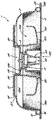
図11に示すように、カートリッジ1は主に、外側部材2と、内側部材3と、ラミネート5とを含む。外側部材2と、内側部材3と、ラミネート5とを組み合わせると、1種類または複数種類の飲料原料を含有するための内部120と、入口121と、出口122と、入口121から出口122までをつないで内部120を貫通する飲料流路とを有するカートリッジ1が形成される。入口121と出口122とは、当初はラミネート5でシールされているが、使用時に、そのラミネート5を穿孔またはカッティング(cutting)することにより開口される。飲料流路は、以下で説明するように、外側部材2と、内側部材3と、ラミネート5との間の空間的相互関係により画定される。この他にも、以下でさらに説明するように、フィルタ4などのコンポーネンツを任意にカートリッジ1に含めることができる。
As shown in FIG. 11, the cartridge 1 mainly includes an
第1の型式のカートリッジ1を、図1から図11に示す。第1の型式のカートリッジ1は、焙煎および挽き作業を施したコーヒーやリーフティなどの濾過生成物の供給に使用するように特に設計されたものである。しかし、この型式のカートリッジ1および、以下で説明する他の型式を、ココア、コーヒー、茶、甘味料類、強壮剤類、調味料類、アルコール飲料類、調味乳、果汁類、スカッシュ類、ソース類、およびデザート類などの他の生成物に使用することも可能である。 A first type of cartridge 1 is shown in FIGS. The first type of cartridge 1 is specifically designed for use in supplying filtered products such as coffee and leaf tea that have been roasted and ground. However, this type of cartridge 1 and the other types described below are cocoa, coffee, tea, sweeteners, tonics, seasonings, alcoholic beverages, seasoned milk, fruit juices, squash, sauces And other products such as desserts can also be used.
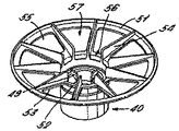
図5からわかるように、カートリッジ1の全体形状は、その直径または幅(breadth)が高さより大幅に大きい略円形またはディスク形状である。長軸Xは、図1に示すように、外側部材の中心を通っている。通常、外側部材2の外径全体は74.5mm±6mmであり、外側の高さ全体は16mm±3mmである。通常、このカートリッジ1の容積は30.2ml±20%である。
As can be seen from FIG. 5, the overall shape of the cartridge 1 is a substantially circular or disk shape whose diameter or breadth is significantly greater than its height. The major axis X passes through the center of the outer member as shown in FIG. Usually, the entire outer diameter of the
本発明でのカートリッジのアスペクト比(aspect ratio)は、2.0バールまでで稼動されるカートリッジでは0.10と0.43との間であり、0.2バールから4.0バールまでで稼動されるカートリッジでは0.42から0.68までである。好ましくは、2.0バールより低い領域で稼動されるカートリッジのアスペクト比は0.21と0.28の間である。アスペクト比とは、1種類または複数種類の飲料原料を含有する内部120の内部幅(カートリッジがディスク型である場合には、内径)に対する、内部120の垂直高さの最大値の比率と定義される。例示される実施態様では、垂直高さの最大値は14.3mmであり、幅(この例では直径と同視される)は57.8mmである。図36に示されるように、本発明のカートリッジから飲料を供給(dispense)するために必要とされる圧力は、カートリッジのアスペクト比に応じて異なる。0.10と0.43との間のアスペクト比は、飲料を調整するのに必要な圧力を抑制する要求と、調整中の飲料の抽出と泡立ちとを最大化する要求とを均衡させるために有利である。 The aspect ratio of the cartridge in the present invention is between 0.10 and 0.43 for cartridges operating up to 2.0 bar, and operating from 0.2 bar to 4.0 bar. In the cartridge to be used, it is from 0.42 to 0.68. Preferably, the aspect ratio of cartridges operating in the region below 2.0 bar is between 0.21 and 0.28. The aspect ratio is defined as the ratio of the maximum value of the vertical height of the interior 120 to the interior width of the interior 120 containing one or more types of beverage ingredients (inner diameter if the cartridge is a disk type). The In the illustrated embodiment, the maximum vertical height is 14.3 mm and the width (equivalent to the diameter in this example) is 57.8 mm. As shown in FIG. 36, the pressure required to dispense beverage from the cartridge of the present invention varies depending on the aspect ratio of the cartridge. An aspect ratio between 0.10 and 0.43 is to balance the need to reduce the pressure required to adjust the beverage with the requirement to maximize the extraction and frothing of the beverage being adjusted. It is advantageous.
より高圧のシステム、典型的にはより大きい容量のカートリッジが用いられるシステムのために、より高い0.42から0.68までのアスペクト比が有用に用いられうる。 Higher aspect ratios from 0.42 to 0.68 can be usefully used for higher pressure systems, typically systems where larger capacity cartridges are used.
非ディスクの形状のカートリッジは、高さの最大値を距離(distance)の最大値で序した値と定義されるアスペクト比をもつことになる。 A non-disc shaped cartridge will have an aspect ratio defined as the maximum height ordered by the maximum distance.
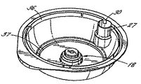
外側部材2は主に、湾曲した環状壁13を有するボウル形状のシェル10と、閉じた頂部11と、開いた底部12とを含む。閉じた頂部11から開いた底部12にかけて環状壁13が広がっているため、外側部材2の直径は、その頂部11にて、底部12の直径に比較して小さくなっている。環状壁13と閉じた底部11とが共に、内部34を有する入れ物を画成している。
The
中空で内側向きの円柱状延出部18が、長軸Xを中心として閉じた頂部11に設けられている。図2でさらによくわかるように、円柱状延出部18は、第1、第2および第3の部分19、20および21を有する階段状プロファイルを含む。第1の部分19は、直円柱状である。第2の部分20は、截頭円錐形状であり、内側に先細りになっている。第3の部分21は、もう1つの直円柱であり、下方面31により閉じられている。第1、第2および第3の部分19、20および21の直径は、円柱状延出部18の頂部11から閉じた下方面31にかけて、円柱状延出部18の直径が狭まるように、段階的に小さくなっている。略水平な肩32が、第2の部分20と第3の部分21との間の結合部分にて円柱状延出部18に形成されている。
A hollow, inwardly extending
外向きに延出する肩33が、底部12に向けて外側部材2に形成されている。この外向きに延出する肩33が、環状壁13と同軸である副次的壁15を形成し、これにより、副次的壁15と環状壁13との間にマニホルド16を形成する環状トラックを画成するようになっている。マニホルド16は、外側部材2の周囲をめぐって通っている。一連のスロット17が、環状壁13にマニホルド16と同じ高さで設けられており、これにより、マニホルド16と外側部材2の内部34との間が気体および液体連通した状態となる。図3に示すように、スロット17は、環状壁13に形成された垂直スリットを含む。20から40本のスリットを設ける。図示した実施形態では、37本のスロット17が、ほぼ等間隔でマニホルド16の周囲に設けられている。スロット17を、好ましくは、1.4から1.8mmの長さとする。通常、各スロットの長さは、外側部材2の高さ全体の10%である1.6mmである。各スロットの幅は、0.25から0.35mmである。通常、各スロットの幅は0.3mmである。スロット17の幅を十分に狭くして、保管時、使用時のいずれかに飲料原料がマニホルド16内に通過してしまわないようにする。
An outwardly extending shoulder 33 is formed on the
入口チャンバ26を、外側部材2の周囲にて外側部材2内に形成する。図5で最もよくわかるように、円柱状壁部27が設けられており、これが外側部材2の内部34に入口チャンバ26を画成し、同時に入口チャンバ26を外側部材2の内部34から仕切っている。この円柱状壁部27は、長軸Xに垂直な1平面上に形成された閉じた上方面28と、外側部材2の底部12と同平面上にある開いた下方端部29とを有する。入口チャンバ26は、図1に示すように、2本のスロット30を介してマニホルド16と連通する。別法として、1から4本のスロットを用いて、マニホルド16と入口チャンバ26との間を連通させてもよい。
An
外向きに延出する肩33の下方端部には、長軸Xに垂直に外向きに延出するフランジ35が設けられている。通常、このフランジ35の幅は2から4mmである。フランジ35の一部が、外側部材2の保持によってハンドル24を形成するように、拡張されている。ハンドル24には、掴みやすくするために先を上向きにしたリム25が設けられている。
A
外側部材2を、高密度ポリエチレン、ポリプロピレン、ポリスチレン、ポリエステル、またはこれらの2種以上の積層体から単体ピースとして形成する。適したポリプロピレンは、DSM UK Limited(Redditch、United Kingdom)から入手可能な一連のポリマー類である。この外側部材は、不透明でも、透明でも、半透明でもよい。この製造処理を射出成形とすることができる。
The
図7から図10に示すように、内側部材3は、環状フレーム41と、下向きに延出する円柱状漏斗40とを含む。図7に示すように、長軸Xは内側部材3の中心を通っている。
As shown in FIGS. 7 to 10, the
図8で最もよくわかるように、環状フレーム41は、外側リム51と、等間隔で設けられた10本の径方向スポーク53で接合されている内側ハブ52とを含む。内側ハブ52は円柱状漏斗40と一体であり、かつ円柱状漏斗40から延出している。濾過口部55が、径方向スポーク53の間で環状フレーム41内に形成されている。この濾過口部55をカバーするように、フィルタ4が環状フレーム41上に配置される。このフィルタを好ましくは、不織繊維材料であるポリエステルなど、湿潤強さの高い材料で製造する。この他に使用可能な材料として、織紙繊維を含むセルロース材料などの水分不透過性セルロース材料が挙げられる。この織紙繊維をポリプロピレン、ポリ塩化ビニルおよび/またはポリエチレンの繊維と混合させることができる。こうしたプラスチック材料をセルロース材料内に組み合わせると、そのセルロース材料がヒートシール可能なものとなる。フィルタ4を、熱および/または圧力で活性化される材料で処理またはコーティングして、熱および/または圧力により環状フレーム41にシールできるようにしてもよい。
As best seen in FIG. 8, the annular frame 41 includes an
図7の断面プロファイルに示すように、内側ハブ52は外側リム51より下の位置に配置されるため、環状フレーム41のプロファイルが、下方に傾斜したものとなる。
As shown in the cross-sectional profile of FIG. 7, the
各スポーク53の上面に、直立型ウェブ54が設けられる。このウェブが、環状フレーム41上方の孔空間を複数の通路57に分割する。各通路57は両側をウェブ54に、また下面をフィルタ4にその境界を接した状態となる。通路57は外側リム51から下方に円柱状漏斗40に向けて延在し、ウェブ54の内側末端部により画成される開口56にて円柱状漏斗40に開いている。
An
円柱状漏斗40は、内側の注ぎ口43を取り囲む外側チューブ42を含む。この外側チューブ42が、円柱状漏斗40の外面を形成している。注ぎ口43はその上方端部にて外側チューブ42に、環状フランジ47により接合されている。注ぎ口43は、その上方端部に位置して通路57の開口56と連通する入口45と、その下方端部に位置し、調製済み飲料を通過させてカップや他の入れ物内に注ぐ出口44とを含む。注ぎ口43は、その上方端部に略截頭円錐状部分48を、またその下方端部に円柱状部分58を含む。この円柱状部分58にわずかに先細る部分を設けて、出口44に向けて幅を細めてもよい。略截頭円錐形部分48を設けることにより、飲料に乱流を起こすことなく、飲料を通路57から出口44に向けて下向きに流動させやすくなる。略截頭円錐形部分48の上面には、円柱状漏斗40の周囲に等間隔で位置する支持ウェブ49を設ける。この支持ウェブ49の間に複数のチャネル50が画定される。支持ウェブ49の上縁部は互いに同じ高さであり、長軸Xに垂直である。
The
内側部材3を、上述したように、外側部材2と同様、ポリプロピレンまたはこれに類似した材料から射出成形により単体ピースとして形成することができる。
As described above, the
別法として、内側部材3および/または外側部材2を、生分解性ポリマーで製造してもよい。適した材料の例として、分解性ポリエチレン(例えば、英国ボアハムウッドのSymphony Environmental製SPITEK)、生分解性ポリエステルアミド(例えば、Symphony Environmental製BAK1095)、ポリ乳酸(米国ミネソタ州のCargil製PLA)、デンプン系ポリマー、セルロース誘導体、およびポリペプチドが挙げられる。
Alternatively, the
ラミネート5は、アルミニウムによる第1の層、および無延伸ポリプロピレンによる第2の層の2層から形成される。このアルミニウム層は0.02から0.07mmの厚さである。無延伸ポリプロピレン層は0.025から0.065mmの厚さである。一実施形態において、アルミニウム層は0.06mmの厚さであり、ポリプロピレン層は0.025mmの厚さである。このラミネートは、組み立て時の巻き込みに高い抵抗を有するため、特に有利である。このため、ラミネート5を、歪みを発生させることなく、正しいサイズおよび形状に事前に切断しておき、その後製造ラインの組み立てステーションに移送することができる。したがって、このラミネート5は溶接(welding)に特に適している。他のラミネート材料も使用可能であり、その例として、PET/アルミニウム/PP、PE/EVOH/PP、PET/金属被覆/PP、およびアルミニウム/PPラミネートが挙げられる。打ち抜き加工した在庫品ではなく、ロールラミネートによる在庫品を用いてもよい。
The
カートリッジ1を、可撓性のラミネートではなく、剛性または半剛性の蓋で閉じてもよい。 The cartridge 1 may be closed with a rigid or semi-rigid lid instead of a flexible laminate.
カートリッジ1の組み立ては、
a)内側部材3を外側部材2に挿入するステップと、
b)フィルタ4を決まった形状に切断し、内側部材3上に配置して、円柱状漏斗40上で受け、環状フレーム41に対向する位置にくるようにするステップと、
c)内側部材3、外側部材2、およびフィルタ4を超音波溶接で接合するステップと、
d)このカートリッジ1に、1種類または複数種類の飲料原料を充填するステップと、
e)ラミネート5を外側部材2に取付けるステップと
を含む。
Assembling the cartridge 1
a) inserting the
b) cutting the filter 4 into a fixed shape, placing it on the
c) joining the
d) filling the cartridge 1 with one or more types of beverage ingredients;
e) attaching the
上記ステップについては、以下でさらに詳細に説明する。
外側部材2を、その開いた底部12を上向きにして方向付ける。次に、内側部材3をその外側部材2内に挿入して、外側リム51がカートリッジ1の頂部11において軸方向延出部14内に遊合状態で受けられるようにする。これと同時に、外側部材2の円柱状延出部18が、内側部材3の円柱状漏斗40の上方部分内に受けられる。円柱状延出部18の閉じた下方面31が内側部材3の支持ウェブ49に当たった状態で、円柱状延出部18の第3の部分21が円柱状漏斗40内に納まる。次に、フィルタ4を、フィルタ材料が環状リム51に接触するように、内側部材3上に配置する。超音波溶接処理により、このフィルタ4を内側部材3に接合し、同時に同一処理ステップにおいて、内側部材3を外側部材2に接合する。内側部材3およびフィルタ4を外側リム51に沿って溶接する。内側部材3および外側部材2は、外側リム51およびウェブ54の上方縁部に沿って溶接線により接合する。
The above steps are described in further detail below.
The
図11で最もよくわかるように、外側部材2および内側部材3を互いに接合すると、環状フランジ41の下方かつ円柱状漏斗40の外側に、内部120内の孔空間130ができ、これが濾過チャンバとなる。この濾過チャンバ130と環状フレーム41上方の通路57とを、濾紙4が隔てる。
As best seen in FIG. 11, when the
濾過チャンバ130には1種類または複数種類の飲料原料200が含有される。1種類または複数種類の飲料原料は、濾過チャンバ130内に包装される。濾過式飲料の場合、この原料は通常、焙煎および挽き作業を施したコーヒーまたはリーフティである。濾過チャンバ130内の飲料原料の包装密度は、所望に応じて変更可能である。通常、濾過式コーヒー生成物の場合、この濾過チャンバは、通常5から14mm厚さの濾過床に5.0から10.2グラムの焙煎および挽き作業を施したコーヒーを含有する。任意に、内部120に、その中で自由に移動できるため、飲料を注ぐ時点で乱流を起こし、その飲料原料の沈殿物を砕いて混合しやすくする球体などの1種類または複数種類の物体を入れてもよい。
The
次に、ラミネート5を外向きに延出するフランジ35の下面に接合するためにラミネート5の周囲に溶接部126を形成することにより、ラミネート5を外側部材2に取付ける。溶接部126を、ラミネート5が入口チャンバ26の円柱状壁部27の下方縁部に対してシールするように延在させる。さらに、溶接部125を、ラミネート5と円柱状漏斗40の外側チューブ42の下方縁部との間に形成する。このラミネート5が、濾過チャンバ130の下方壁となり、かつ入口チャンバ26および円柱状漏斗40をシールする。ただし、ラミネート5と注ぎ口43の下方縁部との間には、供給前に小さな隙間123ができるようになっている。ラミネート5の材料特性に応じて、熱および超音波溶接など、様々な溶接方法が使用可能である。
Next, the
有利には、外側部材2とラミネート5との間に内側部材3がある。この内側部材3を、ポリプロピレンなどの比較的硬い材料で形成する。これにより、内側部材3は、カートリッジ1が圧縮されてもラミネート5と外側部材2との間のスペースを保つように作用する荷重受け部材となる。使用時、カートリッジ1の受ける圧縮荷重を130から280Nとすると好ましい。この圧縮力は、カートリッジが内部加圧下で破損することを防ぐ作用をすると同時に、内側部材3および外側部材2を互いに寄せる役割を果たす。これにより、確実に、カートリッジ1内の通路および口部の内側寸法は固定され、カートリッジ1が加圧されても変化しなくなる。
Advantageously, there is an
このカートリッジ1を使用するには、まず、これを飲料調製機内に挿入し、入口121および出口122を、ラミネート5を穿孔してそれをバックグラウンドに折り返す、その飲料調製機の穴開け部材により開ける。通常は水である、圧力下にある水性媒体を、0.1から2.0バールの圧力でカートリッジ1に入れて、入口121から入口チャンバ26内へ通す。ここから、水はスロット30を通過してマニホルド16を回り、複数のスロット17を介してカートリッジ1の濾過チャンバ130内に入る。この水は、濾過チャンバ130を介して径方向内側に押し入れられ、そこに含有されている飲料原料200と混ざり合う。この水は同時に、その飲料原料内を通って上側に押し上げられる。水がこのように飲料原料内を通過することで形成された飲料は、フィルタ4および濾過口部55を通過して、環状フレーム41上方に位置する通路57内に入る。フィルタ4がスポーク53にシールされ、リム51が外側部材2に溶接されており、他の出口がまったくない状態であるため、この飲料すべてが確実にフィルタ4を通過する。
To use this cartridge 1, first it is inserted into the beverage preparation machine and the
次に、この飲料はウェブ54間に形成された径方向通路57に沿って下向きに流動し、開口56を通過して円柱状漏斗40内に入る。続いて、チャネル50に沿って支持ウェブ47間を通過し、注ぎ口43から下の出口44に落ち、これにより、この飲料はカップなどの入れ物内に注がれる。
The beverage then flows downward along a
好ましくは、飲料調製機に空気パージ性能を含めて、操作サイクルの終了時に圧縮空気をカートリッジ1内に押し入れることにより、残留飲料をその入れ物内に流し出す。 Preferably, the beverage preparation machine includes air purge capability, and the residual beverage is poured into the container by pushing compressed air into the cartridge 1 at the end of the operating cycle.
次に、図12から図18を参照しながら、第2の型式のカートリッジ1について説明する。第2の型式のカートリッジ1は、クレマとして知られる細かい気泡の泡立ちを有する飲料を生成することが望ましい、焙煎および挽き作業を施したコーヒーなどのエスプレッソ型生成物の供給に使用するように特に設計されたものである。第2の型式のカートリッジ1が備える特徴は、その多くが第1の型式のものと同じであるため、同様の参照符号を用いて同様の特徴を指している。以下の説明では、第1の型式と第2の型式との間の違いについて述べる。同様に機能する共通の特徴について、以下では詳細な説明を省略する。 Next, the second type cartridge 1 will be described with reference to FIGS. A second type of cartridge 1 is particularly suitable for use in the supply of espresso type products such as roasted and ground coffee, where it is desirable to produce a beverage with fine bubble foam known as crema. It is designed. Since many of the features of the second type cartridge 1 are the same as those of the first type, the same reference numerals are used to indicate the same features. In the following description, the difference between the first model and the second model will be described. Detailed descriptions of common features that function in the same manner will be omitted below.
外側部材2の構造は、第1の型式のカートリッジ1が備え、図1から図6に示すものと同じである。
The structure of the
内側部材3の環状フレーム41は、第1の型式のものと同じである。また、フィルタ4が、濾過口部55をカバーするように、環状フレーム41上に配置される。円柱状漏斗40の外側チューブ42も、第1の場合と同様である。ただし、第2の型式の内側部材2に、第1の型式の場合と比較していくつか相違点がある。図16に示すように、注ぎ口43に、出口44から注ぎ口43に向けて一部延出する仕切り65が設けられている。この仕切り65を設けることにより、飲料が注ぎ口43を出る際にしぶきを飛ばす、かつ/またははねることを防止しやすくなる。注ぎ口43のプロファイルも異なっており、この注ぎ口43は、チューブ43の上方端部近傍で明確な屈曲部66を備える階段状プロファイルを含む。
The annular frame 41 of the
リム67が、環状フランジ47から直立して設けられて、外側チューブ42と注ぎ口43とを接合している。このリム67は入口45から注ぎ口43までを取り囲み、リム67と外側チューブ42の上方部分との間に環状チャネル69を画成する。リム67には、内向きの肩68が設けられている。リム67周囲の一箇所に、口部70がスロットの形態で設けられており、このスロットは、図12および図13で最もよくわかるように、リム67の上方縁部から肩68の高さよりわずかに下の箇所まで延在するものである。このスロットの幅は0.64mmである。
A
図16および図17に示すように、環状フランジ47に、口部70と周方向に位置合わせされた空気入口71を設ける。この空気入口71は、外側チューブ42と注ぎ口43との間でフランジ47の上方箇所とフランジ47の下方の孔スペースとを流通させるように、フランジ47を貫通する口部を含む。好ましくは、図示のように、空気入口71に、上方略截頭円錐形部分73と下方円柱状部分72とを含める。空気入口71は通常、ピンなどの成形工具により形成される。空気入口71を先細りプロファイルにすると、成形工具を成形原料から取り出しやすくなる。空気入口71に近位である外側チューブ42の壁を、空気入口71から注ぎ口43の入口45へとつながるシュート75を形成する形状とする。図17に示すように、空気入口71とシュート75との間に斜めの肩74が形成されて、スロット70から噴射される飲料が、空気入口71のごく近位にあるフランジ47の上面を直接汚さないようにしている。
As shown in FIGS. 16 and 17, the
第2の型式のカートリッジ1を組み立てる手順は、第1の型式の組み立てと同様である。しかし、いくつかの相違点もある。図18に示すように、円柱状延出部18の第3の部分21は、支持ウェブに対してではなく、支持リム67内に納まる。第2の部分20と第3の部分21との間に位置する円柱状延出部18の肩32は、内側部材3の支持リム67が含む上方縁部に当たる。このようにして、内側部材3と外側部材2との間に、カートリッジ1の周囲のほぼ全体に延び、円柱状延出部18と支持リム67との間の面シールを含む界面ゾーン124が形成される。ただし、支持リム67に形成するスロット70が支持リム67を貫通して肩68のわずか下方の箇所まで下向きに延在しているため、円柱状延出部18と支持リム67との間のシールは流体密ではない。したがって、円柱状延出部18と支持リム67との間が界面嵌合することにより、スロット70が口部128へと変化して、環状チャネル69と注ぎ口43との間を気体および液体連通させている。この口部は通常、その幅が0.64mm、長さが0.69mmである。
The procedure for assembling the second type cartridge 1 is the same as that for the first type assembly. However, there are some differences. As shown in FIG. 18, the
第2の型式のカートリッジ1で飲料を供給する操作は、第1の型式と同様であるが、いくつかの点で異なっている。径方向通路57内の飲料は、ウェブ54間に形成された通路57を下向きに流動して、開口56から円柱状漏斗40の環状チャネル69内に入る。環状チャネル69内に入った後、この飲料は、濾過チャンバ130および通路57内に収集した飲料の背圧により、圧力下で口部128から押出される。したがって、飲料は口部128から噴射されて、注ぎ口43の上方端部が形成する膨張チャンバ内に押出される。図18に示すように、この飲料噴射は、空気入口71上をそのまま通過する。飲料が注ぎ口43に入ると、飲料噴射の圧力が降下する。この結果、空気が空気入口71を介して引き込まれるのと同時に、その空気が飲料流内に多数の小さな気泡として混入される。口部128から出た飲料噴射は、下向きに流れて集まり、出口44までくると、ここでカップなどの入れ物内に注出され、気泡が所望のクレマとなる。したがって、口部128および空気入口71が共に、空気を飲料内に取り込むように作用するエダクタとなる。このエダクタ内への飲料の流動をできる限り滑らかに保ち、圧力損失を低減しなければならない。そのためには有利なことに、エダクタの壁部を凹形表面に製造して、「壁面効果」摩擦による損失を低減しなければならない。口部128の寸法公差は小さい。好ましくは、この口部サイズを0.02mm2前後に定める。毛状物、繊維または他の表面凹凸をエダクタ内、またはエダクタの出口近傍に設けて、空気の取り込み量を増加させることがわかっている有効領域を増加してもよい。
The operation of supplying the beverage with the second type cartridge 1 is similar to the first type, but differs in several respects. Beverage in the
次に、第3の型式のカートリッジ1について説明し、これを図19から図29に示す。第3の型式のカートリッジ1は、粉末、液体、シロップ、ゲルまたはこれに類似の形態でよい溶解性生成物の供給に使用するように特に設計されたものである。この溶解性生成物は、使用時にカートリッジ1内を水などの水性媒体が通過すると、その水性媒体によって溶解する、または水性媒体内に懸濁液を形成する。この飲料例として、ココア、コーヒー、乳、茶、スープ、またはこの他の、水を加えて元に戻す生成物や水溶解性生成物が挙げられる。第3の型式のカートリッジ1が備える特徴は、その多くが第1および第2の型式のものと同じであるため、同様の参照符号を用いて同様の特徴を指している。以下の説明では、第3の型式と第1の型式および第2の型式との間の違いについて述べる。同様に機能する共通の特徴について、以下では詳細な説明を省略する。 Next, a third type of cartridge 1 will be described, which is shown in FIGS. A third type of cartridge 1 is specifically designed for use in supplying a soluble product that may be in the form of a powder, liquid, syrup, gel or the like. When an aqueous medium such as water passes through the cartridge 1 during use, the soluble product is dissolved by the aqueous medium or forms a suspension in the aqueous medium. Examples of this beverage include cocoa, coffee, milk, tea, soup, or other products that are reconstituted with water or water soluble products. Since many of the features of the third type cartridge 1 are the same as those of the first and second types, the same reference numerals are used to indicate the same features. In the following description, differences between the third model, the first model, and the second model will be described. Detailed descriptions of common features that function in the same manner will be omitted below.
第1および第2の型式の外側部材2と比較すると、図20に示すように、第3の型式の外側部材2に含まれる中空で内向きの円柱状延出部18の直径は全体として大きくなっている。具体的に言えば、第1および第2の型式の外側部材2では13.2mmであったところが、第1の部分19の直径は通常16から18mmである。さらに、第1の部分19には、図20で最もよくわかるように、凸状外面19aすなわちバルジが設けられている。このバルジの機能については以下で説明する。しかし、カートリッジ1のうち、第3の部分21の直径は同じである。このため、肩32の面積がこの第3の型式のカートリッジ1では広くなっている。通常、カートリッジ1の容積は、組み立て時で32.5ml±20%である。
Compared with the
環状壁13の下方端部に設けるスロットの数および位置もまた異なっている。3から5本のスロットを設ける。図23に示すように、この実施形態では、4本のスロット36が等間隔でマニホルド16の周囲に設けられている。このスロット36は、第1および第2の型式のカートリッジ1の場合よりわずかに幅広で、0.35から0.45mmであり、好ましくは、0.4mm幅である。
The number and position of the slots provided at the lower end of the
他の点において、カートリッジ1の外側部材2はいずれも同じである。
In other respects, the
内側部材3に含まれる円柱状漏斗40の構造は、第1の型式のカートリッジ1と同じであり、外側チューブ42、注ぎ口45、環状フランジ47、および支持ウェブ49が設けられている。唯一の相違点は、注ぎ口45であり、これは上方略截頭円錐形部分92と下方円柱状部分93とを備える形状となっている。
The structure of the
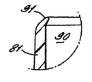
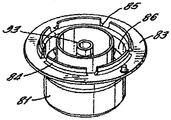
第1および第2の型式と比較すると、図24から図28に示すように、環状フレーム41は、円柱状漏斗40を取り囲み、かつ円柱状漏斗40を環状フランジ47にまたはこの近傍に結合する8本の径方向ストラット87により円柱状漏斗40に接続されているスカート部分80に置き換えられている。このスカート部分80からは、円柱状の延出部81がストラット87から上向きに延出して、上面が開いたチャンバ90を画成している。円柱状延出部81の上方リム91は、図26に示すように、内向きプロファイルを有する。スカート部分80の環状壁82は、ストラット87から下向きに延在して、スカート部分80と外側チューブ42との間に環状チャネル86を画成している。
Compared to the first and second types, as shown in FIGS. 24 to 28, the annular frame 41 surrounds the
環状壁82は、その下方端部に、長軸Xに垂直に位置する外側フランジ83を含んでいる。リム84が、フランジ83の下面から下向きにぶら下がり、リム84に沿って周方向に等間隔な5個の口部85を具備している。したがって、リム84の下方は、城砦型プロファイルとなっている。
The annular wall 82 includes an
ストラット87間に口部89を設けることにより、チャンバ90と環状チャネル86との間を連通させている。
By providing an opening 89 between the
第3の型式のカートリッジ1を組み立てる手順は、第1の型式の組み立てと同様であるが、いくつかの相違点もある。図29に示すように、外側部材2と内側部材3とは、互いに溶接されるのではなく、互いに押し嵌めされ、スナップ嵌合構造により保持される。この2つの部材の接合時、内向き円柱状延出部18が、スカート部分80の上方円柱状延出部81の内側に受けられる。内側部材3は、円柱状延出部18に含まれる第1の部分19の凸状外表面19aが上方円柱状延出部81の内向きリム91と摩擦係合することにより、外側部材2内に保持される。
The procedure for assembling the third type cartridge 1 is similar to the first type assembly, but there are also some differences. As shown in FIG. 29, the
内側部材3が外側部材2内に配置した状態になると、混合チャンバ134が、スカート部分80の外側に画成される。この混合チャンバ134が、供給前の飲料原料200を含有する。4つの入口36と5つの口部85とが互い違いに周方向に配置されることに留意されたい。内側部材3および外側部材2を相対的にどのように位置決めしても4つの入口36および5つの口部85を用いることで確実にこの入口と口部との間に位置のずれが発生するため、この2つの部品の互いに対する径方向位置を組み立て時に決定または固定しなくてもよい。
When the
1種類または複数種類の飲料原料を、カートリッジの混合チャンバ134内に包装する。この混合チャンバ134内における飲料原料の包装密度は所望に応じて変更可能である。
One or more beverage ingredients are packaged in the mixing
次に、ラミネート5を内側部材3および外側部材2に、第1および第2の型式において上述したように取付ける。
Next, the
使用時、第1および第2の形式のカートリッジと同様に、水が、4本のスロット36を通って混合チャンバ134に入る。この水が径方向内側に混合チャンバ内に押し入れられ、そこに含有されている飲料原料と混ざり合う。この水の中に生成物が溶解または混合されて、混合チャンバ134内に飲料が形成され、これが、混合チャンバ134内の飲料および水の背圧により、口部85から環状チャネル86内に駆逐される。4つの入口36と5つの口部85とが互い違いに周方向に配置されることにより、水の噴射が入口スロット36から径方向に直接口部85内に入ることは、まず混合チャンバ134内で循環が発生しない限り、あり得ない。このため、生成物の溶解または混合の程度および安定性は大幅に高まる。形成された飲料は、環状チャネル86内を上方向に押し上げられ、ストラット87間の口部89を通ってチャンバ90内に入る。次にチャンバ90から支持ウェブ49間の入口45を介して注ぎ口43に入り、出口44までくると、ここでカップなどの入れ物内に注がれる。このカートリッジを、粘稠液またはゲルの形態である飲料原料に適用できることがわかっている。一用途において、カートリッジ1内には、周囲温度にて粘性が1700〜3900mPa、0℃にて5000〜10000mPaであり、屈折固形分が67ブリックス度±3である液状チョコレート原料が入れられる。別の用途において、カートリッジ1内には、周囲温度にて粘性が70〜2000mPa、0℃にて80〜5000mPaであり、全固形分量が40から70%である液体コーヒーが入れられる。この液状コーヒー原料に、0.1〜2.0重量%、好ましくは0.5〜1.0重量%の重炭酸ナトリウムを含有させることができる。重炭酸ナトリウムは、コーヒーのpHレベルを4.8以下に維持して、コーヒーを充填したカートリッジの貯蔵寿命を最長12ヶ月にできるように作用するものである。
In use, water enters the mixing
第4の型式のカートリッジ1を図30から図34に示す。第4の型式のカートリッジ1は、濃縮型液状乳などの液状生成物の供給に用いるように特に設計されたものである。第4の型式のカートリッジ1に含まれる特徴は、その多くが第1から第3の型式のものと同じであるため、同様の参照符号を用いて同様の特徴を指す。以下の説明では、第4の型式と第1から第3の型式との間の違いについて述べる。同様に機能する共通の特徴について、以下では詳細な説明を省略する。 A fourth type of cartridge 1 is shown in FIGS. The fourth type of cartridge 1 is specifically designed for use in the supply of liquid products such as concentrated liquid milk. Since many of the features included in the fourth type cartridge 1 are the same as those of the first to third types, the same reference numerals are used to indicate the same features. In the following description, the difference between the fourth model and the first to third models will be described. Detailed descriptions of common features that function in the same manner will be omitted below.
外側部材2は、第3の型式のカートリッジ1の、図19から図23に示すものと同じである。
The
内側部材3の円柱状漏斗40は、第2の型式のカートリッジ1に類似しているが、いくつかの点で異なる。図30に示すように、注ぎ口43は、上方略截頭円錐部分106と、下方円柱状部分107とを含む形状である。この注ぎ口43の内面には3つの軸方向リブ105が設けられて、供給された飲料を下向きに出口44に方向付け、注がれた飲料が注ぎ口内で旋回しないようにしている。したがって、リブ105はバッフルとして作用する。第2の型式のカートリッジ1と同様、空気入口71が環状フランジ47を貫通して設けられている。しかし、空気入口71の下のシュート75は、第2の型式の場合より細長くなっている。
The
スカート部分80が、上述した第3の型式のカートリッジ1に示したものと同様に設けられている。5から12個の口部85がリム84内に設けられている。第3の型式のカートリッジ1では5個であったが、通常10個の口部を設ける。 A skirt portion 80 is provided similar to that shown in the third type of cartridge 1 described above. Five to twelve mouths 85 are provided in the rim 84. In the third type of cartridge 1, the number is five, but usually ten mouths are provided.
スカート部分80のフランジ83から、これと一体となって延出している環状ボウル100が設けられている。この環状ボウル100は、上方口104を上向きに開いたフレア型本体101を含む。図30および図31に示す4個の送り口部103が、この本体101内にて、スカート部分80と接合するボウル100の下方端部に、またはその近傍に配置されている。好ましくは、この送り口部をボウル100の周囲に等間隔で配置する。
An
ラミネート5は、これまでの実施形態で説明したタイプのものである。
The
第4の型式のカートリッジ1の組み立て手順は、第3の型式の手順と同様である。 The assembly procedure of the fourth type cartridge 1 is the same as that of the third type.
第4の型式のカートリッジ1の操作は、第3の型式の操作と同様である。水が、第1から第3の形式のカートリッジと同様に、カートリッジ1および混合チャンバ134に入る。ここで、上述したように、水が液体生成物と混ざり合い、これを希釈して、上述したように、ボウル100の下の口部85を通り、出口44に向けて押出される。図34に示すように、環状ボウル100に当初含有される一定割合の液体生成物は、混合チャンバ134に入った水によりすぐに希釈されるわけではない。混合チャンバ134の下方部分にある希釈された液体生成物は、上方口104から環状ボウル100内に押し上げられるのではなく、口部85から出て行くことになる。したがって、環状ボウル100内の液体生成物は、混合チャンバ134の下方部分にある生成物と比較して、操作サイクルの最初の段階ではまだ比較的濃縮状態を保っている。環状ボウル100内の液体生成物は、重力を受けて送り口部103から、混合チャンバ134内にてボウル100の下で口部85を通過する生成物流内へと滴下される。環状ボウル100は、一定量の濃縮液体生成物を取り置き、操作サイクル中、定期的に液体流路内にそれを注出することにより、円柱状漏斗40に入る希釈済み液体生成物の濃度を平均化する作用をする。これを、およそ15秒の操作サイクル間における、全固形分含有量の割合として測定される乳の濃度を示す図35aに例示する。線aはボウル100を設けた場合の濃度プロファイルを例示し、線bはボウル100を設けないカートリッジの場合を例示したものである。この図からわかるように、カップ100を設けた場合の濃度プロファイルのほうが、操作サイクル中、均等であり、ボウル100を設けない場合には起こっている急激な濃度の大幅低下がない。この乳の初期濃度は通常、30から35%SSであり、サイクル終了時にはこれが10%SSとなる。これによる希釈率はおよそ3倍であるが、本発明では1倍から6倍までの希釈率が可能である。他の液体飲料原料の場合、この濃度を変更することができる。例えば、液状チョコレートの場合、初期濃度はおよそ67%SSであり、サイクル終了時にはこれが12から15%SSとなる。これによる希釈率(供給飲料内における飲料原料に対する水性媒体の比率)はおよそ5倍であるが、本発明では2倍から10倍までの希釈率が可能である。液体コーヒーの場合、初期濃度はおよそ40から67%SSであり、供給終了時にはこれが1から2%SSとなる。これによる希釈率はおよそ20倍から70倍であるが、本発明では10倍から100倍までの希釈率が可能である。
The operation of the fourth type cartridge 1 is the same as the operation of the third type. Water enters the cartridge 1 and the mixing
こうした飲料は、圧力下で押出されて、濾過チャンバ134およびチャンバ90に収集される飲料の背圧により、環状チャネル86から口部128を通過する。したがって、飲料は口部128から噴射されて、注ぎ口43の上方端部が形成する膨張チャンバ内に押出される。図34に示すように、この飲料噴射は、空気入口71上をそのまま通過する。飲料が注ぎ口43に入ると、飲料噴射の圧力が降下する。この結果、空気が空気入口71を介して引き込まれるのと同時に、その空気が飲料流内に多数の小さな気泡として混入される。口部128から出た飲料噴射は、下向きに流れて集まり、出口44までくると、ここでカップなどの入れ物内に注がれ、気泡が所望の泡立った外観を形成する。
Such beverages are extruded under pressure and pass through the
有利なことに、内側部材3、外側部材2、ラミネート5、およびフィルタ4はすべて、別個のコンポーネンツであり、個別には蛇行通路や細い隙間を含んでいないため、これらを容易に殺菌消毒することができる。必要な通路が形成されるのは、殺菌消毒後にこれらのコンポーネンツを結合した時点である。これは、飲料原料が液状乳濃縮物などの乳原料を主原料とする生成物である場合に特に重要である。
Advantageously, the
飲料カートリッジの第4の実施形態は、液状乳などの濃縮した乳原料を主原料とする液体生成物の供給に特に有利である。これまで、粉末状の乳生成物は、小袋の形態で提供され、これを事前に調製した飲料に加えるようになっていた。しかし、カプチーノタイプ飲料の場合、乳を泡立てる必要がある。これはこれまで、液状乳生成物に蒸気を通すことで実施されてきた。しかし、これには、蒸気供給用設備が必要であるため、この飲料の供給に用いる機械のコストならびに複雑度が増してしまう。また、蒸気を使用すると、カートリッジ操作時に怪我を負う危険性も高まる。したがって、本発明は、濃縮した乳原料を主原料とする液体生成物を中に有する飲料カートリッジを提供するものである。乳生成物を濃縮した場合、新鮮な乳またはUHT乳と比較すると、特定容積の乳に対してより多くの量の泡沫を生成できることがわかっている。これを利用すれば、乳用カートリッジに必要なサイズが縮小される。新鮮な半脱脂乳は、およそ1.6%の脂肪分および10%の全固形分を含む。本発明による濃縮型液状乳調製物は、0.1から12%の脂肪分および25から40%の全固形分を含む。一典型的実施例では、この調製物は4%の脂肪分および30%の全固形分を含む。この濃縮型乳調製物は、以下に記載するように低圧調製機械による泡立てに適している。具体的に言えば、この乳の泡立てを、上述した第4の実施形態のカートリッジを用い、2バール未満、好ましくはおよそ1.5バールの圧力で行う。 The fourth embodiment of the beverage cartridge is particularly advantageous for the supply of a liquid product whose main ingredient is a concentrated milk ingredient such as liquid milk. In the past, powdered milk products have been provided in the form of sachets, which have been added to pre-prepared beverages. However, in the case of cappuccino-type beverages, it is necessary to foam the milk. This has been done so far by passing steam through the liquid milk product. However, this requires steam supply equipment, which increases the cost and complexity of the machine used to supply this beverage. The use of steam also increases the risk of injury during cartridge operation. Accordingly, the present invention provides a beverage cartridge having therein a liquid product mainly composed of concentrated milk ingredients. It has been found that when the milk product is concentrated, a greater amount of foam can be produced for a particular volume of milk when compared to fresh or UHT milk. If this is utilized, the size required for the milk cartridge is reduced. Fresh semi-fat milk contains approximately 1.6% fat and 10% total solids. The concentrated liquid milk preparation according to the present invention comprises 0.1 to 12% fat and 25 to 40% total solids. In one exemplary embodiment, the preparation contains 4% fat and 30% total solids. This concentrated milk preparation is suitable for whipping with a low pressure preparation machine as described below. Specifically, this milk frothing is performed using the cartridge of the fourth embodiment described above at a pressure of less than 2 bar, preferably about 1.5 bar.
濃縮乳を泡立てることは、カプチーノおよびミルクセーキなどの飲料に特に都合がよい。好ましくは、乳を口部128から空気入口71上に通過させ、任意にボウル100を用いて、乳の40%を超える量、好ましくは、70%を超える量を泡立てられるようにする。液状チョコレートの場合、70%を超える量の泡立てが可能である。液状コーヒーの場合、70%を超える量の泡立てが可能である。泡沫性(formability)のレベルは、供給した液体飲料原料の容積に対して生成された泡沫容積の比率として測定される。例えば、138.3mlの飲料が供給され、そのうち58.3mlが泡沫となった場合、泡沫性は、[58.3/(138.3−58.3)]*100=72.9%となる。この乳(および他の液体原料)の泡沫性は、図35bでわかるように、ボウル100を設けることで高められる。ボウル100を設けて供給した乳の泡沫性(線a)は、ボウルを設けずに供給した乳の泡沫性(線b)より高くなっている。これは、乳の泡沫性が乳の濃度に正比例し、図35aに示すように、ボウル100が操作サイクルの大半で乳の濃度を高く維持するためである。また、乳の泡沫性は、図35cに示すように、水性媒体の温度に正比例することも知られている。したがって、水性媒体が最も高温である操作サイクルの終了近くまで、より多くの乳がカートリッジ内に残るため、ボウル100を設けると有利となる。これによりさらに、泡沫性が改良される。
Foaming concentrated milk is particularly convenient for beverages such as cappuccino and milk shakes. Preferably, the milk is passed from the
第4の実施形態のカートリッジも、液状コーヒー生成物の供給に有利である。 The cartridge of the fourth embodiment is also advantageous for supplying a liquid coffee product.
本発明によるこの実施形態の飲料カートリッジから有利なことに、従来技術によるカートリッジと比較して、煎出した飲料の安定性を改良できることがわかっている。以下に示す表1を参照すると、焙煎および挽き作業を施したコーヒーを含有するカートリッジAおよびカートリッジBそれぞれについて、20試料を煎出して得られた収率が示されている。カートリッジAは、本発明の第1の実施形態による飲料カートリッジである。カートリッジBは、本願出願人による特許文献1に記載された従来技術による飲料カートリッジである。煎出した飲料の屈折率をブリックス度で測定し、これを、標準表および式を用いて溶解性固形分の比率(%SS)に変換する。以下の実施例において、
%SS=0.7774*(ブリックス度値)+0.0569
%収率=(%SS*煎出量(g))/(100*コーヒー重量(g))
である。
Advantageously, the beverage cartridge of this embodiment according to the present invention has been found to be able to improve the stability of brewed beverages compared to cartridges according to the prior art. Referring to Table 1 below, the yields obtained by brewing 20 samples for each of cartridge A and cartridge B containing roasted and ground coffee are shown. The cartridge A is a beverage cartridge according to the first embodiment of the present invention. The cartridge B is a beverage cartridge according to the prior art described in Patent Document 1 by the present applicant. The refractive index of the brewed beverage is measured in Brix degrees, which is converted to a soluble solids ratio (% SS) using a standard table and formula. In the following examples:
% SS = 0.7774 * (Brix degree value) +0.0569
% Yield = (% SS * decoction amount (g)) / (100 * coffee weight (g))
It is.

上記データについてt検定統計分析を行ったところ、以下の結果を得た。 When t-test statistical analysis was performed on the above data, the following results were obtained.
この分析から、煎出濃さに匹敵する収率の安定性は、標準偏差が0.88%であった本発明によるカートリッジについて、従来技術によるカートリッジの標準偏差2.24%と比較して、より大幅に高かった(95%の信頼水準)ことがわかる。これは、本発明によるカートリッジにより煎出した飲料の濃さのほうが、再現可能かつ均一であるということである。これは、同じ飲料を何度も味わいたく、その煎出濃さを恣意に変更したくない消費者に好ましい。 From this analysis, the yield stability comparable to the decoction concentration is compared to the standard deviation of 2.24% for the cartridge according to the prior art for the cartridge according to the present invention with a standard deviation of 0.88%, It can be seen that it was significantly higher (95% confidence level). This means that the strength of the beverage brewed by the cartridge according to the invention is reproducible and uniform. This is preferred for consumers who want to taste the same beverage over and over and do not want to change its brewing intensity arbitrarily.
上述したカートリッジの材料に、バリアコーティングを施して、酸素および/または湿気、および/または他の汚染侵入物に対する防御性を改良してもよい。このバリアコーティングを施すと、飲料原料がカートリッジから漏れることに対する防御性を改良し、かつ/または飲料原料に悪影響を与えかねないカートリッジ材料からの抽出物滲出の程度を抑えることができる。バリアコーティングの材料を、PET、ポリアミド、EVOH、PVDCまたは金属化材料からなる群から選択することができる。バリアコーティングの適用には、いくつかの機構が利用可能であり、その例として、これらに限定するものではないが、蒸着、真空蒸着、プラズマコーティング、共押出加工、インモールドラベリング、および二段/多段成形が挙げられる。 Barrier coatings may be applied to the cartridge materials described above to improve protection against oxygen and / or moisture and / or other contaminant intrusions. By applying this barrier coating, it is possible to improve the protection against the leakage of beverage ingredients from the cartridge and / or to reduce the extent of extract exudation from the cartridge material that may adversely affect the beverage ingredients. The material of the barrier coating can be selected from the group consisting of PET, polyamide, EVOH, PVDC or metallized material. Several mechanisms are available for the application of barrier coatings, including but not limited to vapor deposition, vacuum deposition, plasma coating, coextrusion, in-mold labeling, and two-stage / Multi-stage molding is exemplified.
Claims (11)
前記カートリッジはディスク形であり、且つ前記貯蔵チャンバの幅に対する前記貯蔵チャンバの高さのアスペクト比が0.10と0.43との間であることを特徴とするカートリッジ(1)。A cartridge (1) containing one or more types of beverage ingredients (200) and formed from a material that is substantially impermeable to air and moisture, said one or more types of beverages An annular storage chamber (130; 134) containing raw material and an annular manifold (16) surrounding the storage chamber (130; 134), the manifold allowing flow from the manifold to the storage chamber; A filter having one or more inlets (17; 36), the cartridge further being arranged between the storage chamber (130; 134) and at least a part of the lower surface of the top (11) of the cartridge (4) and one or more passages (57) formed between the filter (4) and the top of the cartridge. The one or more passages (57) communicates with the outlet (44) of the center of the cartridge, whereby, one or more inlets of the storage chamber; a (17 36) to the outlet (44) A cartridge in which a flow path of connected beverages flows upwardly through the filter (4) into the one or more passages (57),
The cartridge (1), wherein the cartridge is disk-shaped and the aspect ratio of the height of the storage chamber to the width of the storage chamber is between 0.10 and 0.43.
前記貯蔵チャンバの幅に対する前記貯蔵チャンバの高さのアスペクト比が0.42と0.68との間であり、
前記カートリッジは更に、前記貯蔵チャンバ(130;134)と前記カートリッジの頂部(11)の下面の少なくとも一部との間に配置されたフィルタ(4)と、前記フィルタ(4)と前記カートリッジの頂部との間に形成された1つまたはそれ以上の通路(57)とを含み、該1つまたはそれ以上の通路(57)は前記カートリッジの中央の出口(44)に連通し、これによって、前記貯蔵チャンバの1つまたはそれ以上の入口(17;36)を出口(44)に連結している飲料の流路が上向きに前記フィルタ(4)を通じて前記1つまたはそれ以上の通路(57)内へと流通することを特徴とするカートリッジ。Used with an aqueous medium at a pressure of 2.0 to 4.0 bar, formed of a material containing one or more beverage ingredients (200) and substantially impermeable to air and moisture An annular storage chamber (130; 134) containing the one or more beverage ingredients (200) and an annular manifold (16) surrounding the storage chamber (130; 134), the manifold comprising: A disc-shaped cartridge (1) having one or more inlets (17; 36) allowing flow from a manifold to the storage chamber,
The aspect ratio of the height of the storage chamber to the width of the storage chamber is between 0.42 and 0.68;
The cartridge further includes a filter (4) disposed between the storage chamber (130; 134) and at least a portion of the lower surface of the top (11) of the cartridge, and the top of the filter (4) and the cartridge. One or more passages (57) formed between the cartridge and the one or more passages (57) in communication with the central outlet (44) of the cartridge, whereby A beverage flow path connecting one or more inlets (17; 36) of the storage chamber to an outlet (44) is directed upwardly through the filter (4) into the one or more passages (57). A cartridge characterized by being distributed to.
Applications Claiming Priority (2)
| Application Number | Priority Date | Filing Date | Title |
|---|---|---|---|
| GB0301708A GB2397498B (en) | 2003-01-24 | 2003-01-24 | Cartridge and method for the preparation of beverages |
| PCT/GB2004/000282 WO2004064584A1 (en) | 2003-01-24 | 2004-01-23 | Cartridge and method for the preparation of beverages |
Related Child Applications (1)
| Application Number | Title | Priority Date | Filing Date |
|---|---|---|---|
| JP2010215305A Division JP5665457B2 (en) | 2003-01-24 | 2010-09-27 | Cartridge and method for preparing a beverage |
Publications (2)
| Publication Number | Publication Date |
|---|---|
| JP2006518226A JP2006518226A (en) | 2006-08-10 |
| JP4624342B2 true JP4624342B2 (en) | 2011-02-02 |
Family
ID=9951777
Family Applications (3)
| Application Number | Title | Priority Date | Filing Date |
|---|---|---|---|
| JP2006500240A Expired - Fee Related JP4624342B2 (en) | 2003-01-24 | 2004-01-23 | Cartridge and method for preparing a beverage |
| JP2010215305A Expired - Fee Related JP5665457B2 (en) | 2003-01-24 | 2010-09-27 | Cartridge and method for preparing a beverage |
| JP2013251418A Expired - Fee Related JP5836353B2 (en) | 2003-01-24 | 2013-12-04 | Cartridge and method for preparing a beverage |
Family Applications After (2)
| Application Number | Title | Priority Date | Filing Date |
|---|---|---|---|
| JP2010215305A Expired - Fee Related JP5665457B2 (en) | 2003-01-24 | 2010-09-27 | Cartridge and method for preparing a beverage |
| JP2013251418A Expired - Fee Related JP5836353B2 (en) | 2003-01-24 | 2013-12-04 | Cartridge and method for preparing a beverage |
Country Status (21)
| Country | Link |
|---|---|
| EP (1) | EP1440636B1 (en) |
| JP (3) | JP4624342B2 (en) |
| KR (1) | KR101073747B1 (en) |
| CN (1) | CN100548198C (en) |
| AR (1) | AR044748A1 (en) |
| AT (1) | ATE453350T1 (en) |
| AU (1) | AU2004206098A1 (en) |
| BR (1) | BRPI0406890A (en) |
| CA (1) | CA2513723C (en) |
| DE (1) | DE602004024837D1 (en) |
| ES (1) | ES2337138T3 (en) |
| GB (1) | GB2397498B (en) |
| HK (1) | HK1065691A1 (en) |
| LT (1) | LT2005073A (en) |
| MX (1) | MXPA05007868A (en) |
| NO (1) | NO20053938L (en) |
| PE (1) | PE20040887A1 (en) |
| PL (1) | PL206809B1 (en) |
| RU (1) | RU2337601C2 (en) |
| TW (1) | TWI324054B (en) |
| WO (1) | WO2004064584A1 (en) |
Cited By (1)
| Publication number | Priority date | Publication date | Assignee | Title |
|---|---|---|---|---|
| JP2011045727A (en) * | 2003-01-24 | 2011-03-10 | Kraft Foods Research & Development Inc | Cartridge and method for preparation of beverage |
Families Citing this family (38)
| Publication number | Priority date | Publication date | Assignee | Title |
|---|---|---|---|---|
| GB2411106B (en) * | 2004-02-17 | 2006-11-22 | Kraft Foods R & D Inc | Cartridge for the preparation of beverages |
| JP4754568B2 (en) * | 2005-05-06 | 2011-08-24 | 信越ポリマー株式会社 | Substrate storage container and manufacturing method thereof |
| ATE512098T1 (en) * | 2005-06-22 | 2011-06-15 | Friesland Brands Bv | HOLDING DEVICE AND CUP WITH CONCENTRATE FOR PRODUCING HOT DRINKS |
| NL1029312C2 (en) * | 2005-06-22 | 2006-12-27 | Friesland Brands Bv | Cup used to prepare beverage by means of hot water appliance has covering layer with liquid-permeable perforations and surface that serves as inlet aperture for receiving liquid suitable for preparation substance |
| ITGE20050010U1 (en) * | 2005-10-19 | 2007-04-20 | Ariete Spa | DISPOSABLE CARTRIDGE-FILTER FOR ESPRESSO COFFEE MACHINES. |
| NZ579245A (en) * | 2007-03-23 | 2011-03-31 | Nestec Sa | Beverage ingredient capsule with opening plate having capilliary pressure-relief openings |
| JP5400039B2 (en) | 2007-06-05 | 2014-01-29 | ネステク ソシエテ アノニム | Capsule and method for producing food liquid by centrifugation |
| PL2155021T3 (en) | 2007-06-05 | 2011-09-30 | Nestec Sa | Capsule system, device and method for preparing a food liquid contained in a receptacle by centrifugation |
| DK2152607T3 (en) | 2007-06-05 | 2012-04-23 | Nestec Sa | DISPOSAL CAPS FOR PREPARING A FOOD FLUID BY CENTRIFUGATION |
| US8431175B2 (en) | 2007-06-05 | 2013-04-30 | Nestec S.A. | Method for preparing a beverage or food liquid and system using brewing centrifugal force |
| ATE504228T1 (en) | 2007-06-05 | 2011-04-15 | Nestec Sa | METHOD FOR PRODUCING A DRINK OR LIQUID FOOD |
| EP2330953B1 (en) | 2008-09-02 | 2015-06-03 | Nestec S.A. | Method for preparing a food liquid contained in a capsule by centrifugation and system adapted for such method |
| WO2010026053A1 (en) | 2008-09-02 | 2010-03-11 | Nestec S.A. | Controlled beverage production device using centrifugal forces |
| JP5497778B2 (en) | 2008-12-09 | 2014-05-21 | ネステク ソシエテ アノニム | Liquid food preparation system for preparing liquid food by centrifugation |
| DK2952125T3 (en) | 2009-06-17 | 2021-06-28 | Douwe Egberts Bv | Capsule FOR PREPARING A BEVERAGE |
| CN102573582B (en) | 2009-06-17 | 2017-04-26 | 皇家戴维艾格伯茨有限公司 | System and method for preparing a quantity-on-schedule beverage suitable for consumption |
| PT2308776E (en) | 2009-08-19 | 2013-08-26 | Nestec Sa | Capsule system comprising a capsule and a water injection device |
| US8658232B2 (en) | 2009-08-28 | 2014-02-25 | Nestec S.A. | Capsule system for the preparation of beverages by centrifugation |
| GB2475291B (en) | 2009-11-12 | 2012-03-28 | Kraft Foods R & D Inc | Beverage preparation machines |
| CA2781963C (en) | 2009-12-08 | 2014-01-07 | International Paper Company | Thermoformed articles made from reactive extrusion products of biobased materials |
| MX2012006502A (en) * | 2009-12-08 | 2012-07-03 | Nestec Sa | Capsule system with flow adjustment means. |
| GB2481068B (en) | 2010-06-11 | 2012-06-20 | Kraft Foods R & D Inc | Cartridge for the preparation of beverages |
| EP2394539B1 (en) * | 2010-06-11 | 2013-12-04 | Alain Frydman | Bi-material capsule |
| IT1401828B1 (en) * | 2010-09-28 | 2013-08-28 | Macchiavelli Srl | SYSTEM FOR THE PREPARATION OF A BEVERAGE FROM AN INFUSION PRODUCT CONTAINED IN AN INTERCHANGEABLE CAPSULE |
| GB2493211B (en) | 2011-07-29 | 2014-01-22 | Kraft Foods R & D Inc | A method and a system for making a beverage, and a beverage cartridge |
| WO2013076519A1 (en) | 2011-11-22 | 2013-05-30 | Tuttoespresso S.R.L. | Capsule for beverage preparation |
| CN104093338B (en) * | 2011-12-26 | 2016-11-16 | 皇家飞利浦有限公司 | For brewing the device of component in a solvent |
| US20150232263A1 (en) * | 2012-09-05 | 2015-08-20 | Nestec S.A | Beverage capsule with anti-dripping membrane |
| US10450130B2 (en) * | 2012-09-12 | 2019-10-22 | Kraft Foods R & D, Inc. | Cartridges, systems and methods for preparation of beverages |
| US9783361B2 (en) | 2013-03-14 | 2017-10-10 | Starbucks Corporation | Stretchable beverage cartridges and methods |
| US10442610B2 (en) | 2014-03-11 | 2019-10-15 | Starbucks Corporation | Pod-based restrictors and methods |
| GB2527292A (en) * | 2014-06-13 | 2015-12-23 | Kraft Foods R&D Inc | Cartridge for the preparation of beverages |
| US9877495B2 (en) | 2015-01-09 | 2018-01-30 | Starbucks Corporation | Method of making a sweetened soluble beverage product |
| DE102015115250A1 (en) * | 2015-09-10 | 2017-03-16 | Pester Pac Automation Gmbh | Use of a packaging |
| EP3272672B2 (en) | 2016-07-19 | 2023-02-15 | Delica AG | Capsule |
| CA3041722A1 (en) | 2016-11-09 | 2018-05-17 | Pepsico, Inc. | Carbonated beverage makers, methods, and systems |
| WO2021177829A1 (en) | 2020-03-04 | 2021-09-10 | Liposoma Health B.V. | Cartridges containing lipid formulations for health ingredient-containing hot drinks |
| NL2029172B1 (en) | 2021-09-10 | 2023-03-21 | Liposoma Health B V | Lipid formulations for the preparation of health ingredient-containing hot drinks |
Family Cites Families (10)
| Publication number | Priority date | Publication date | Assignee | Title |
|---|---|---|---|---|
| US1576735A (en) * | 1921-10-08 | 1926-03-16 | Reginald A Fessenden | Infusor |
| US3083101A (en) * | 1959-04-06 | 1963-03-26 | Noury Jean | Refill for filtration coffee-pot |
| ATE142974T1 (en) * | 1990-07-27 | 1996-10-15 | Nestle Sa | CLOSED CARTRIDGE FOR PREPARING A BEVERAGE AND METHOD AND DEVICE FOR PRODUCING THE SAME |
| ATE93373T1 (en) * | 1990-07-27 | 1993-09-15 | Nestle Sa | METHOD FOR BREWING CLOSED PORTION PACKS AND APPARATUS FOR CARRYING OUT THESE METHOD. |
| CA2083324A1 (en) * | 1992-02-03 | 1993-08-04 | Shirdan J. Grykiewicz | Brew basket |
| GB9316717D0 (en) * | 1993-08-11 | 1993-09-29 | Gen Foods Ltd | Cartridge and method for the preparation fo whipped beverages |
| WO1995007648A1 (en) * | 1993-09-17 | 1995-03-23 | Mars G.B. Limited | Beverage brewing |
| WO1995016377A1 (en) * | 1993-12-13 | 1995-06-22 | Ferr-Max Kft. | Method of and apparatus for preparing a frothy coffee beverage, especially for household use |
| GB0003355D0 (en) | 2000-02-14 | 2000-04-05 | Kraft Jacobs Suchard Limited | Cartridge and method for the preparation of whipped beverages |
| GB2397498B (en) * | 2003-01-24 | 2006-01-04 | Kraft Foods R & D Inc | Cartridge and method for the preparation of beverages |
-
2003
- 2003-01-24 GB GB0301708A patent/GB2397498B/en not_active Expired - Lifetime
-
2004
- 2004-01-23 MX MXPA05007868A patent/MXPA05007868A/en unknown
- 2004-01-23 KR KR1020057013573A patent/KR101073747B1/en active IP Right Grant
- 2004-01-23 ES ES04250388T patent/ES2337138T3/en not_active Expired - Lifetime
- 2004-01-23 PL PL377941A patent/PL206809B1/en unknown
- 2004-01-23 AT AT04250388T patent/ATE453350T1/en not_active IP Right Cessation
- 2004-01-23 RU RU2005126733/12A patent/RU2337601C2/en active
- 2004-01-23 CN CNB2004800074048A patent/CN100548198C/en not_active Expired - Lifetime
- 2004-01-23 AU AU2004206098A patent/AU2004206098A1/en not_active Abandoned
- 2004-01-23 AR ARP040100195A patent/AR044748A1/en unknown
- 2004-01-23 DE DE602004024837T patent/DE602004024837D1/en not_active Expired - Lifetime
- 2004-01-23 EP EP04250388A patent/EP1440636B1/en not_active Expired - Lifetime
- 2004-01-23 WO PCT/GB2004/000282 patent/WO2004064584A1/en active Application Filing
- 2004-01-23 CA CA2513723A patent/CA2513723C/en not_active Expired - Lifetime
- 2004-01-23 JP JP2006500240A patent/JP4624342B2/en not_active Expired - Fee Related
- 2004-01-23 BR BR0406890-4A patent/BRPI0406890A/en not_active IP Right Cessation
- 2004-01-26 PE PE2004000099A patent/PE20040887A1/en not_active Application Discontinuation
- 2004-01-27 TW TW093101692A patent/TWI324054B/en not_active IP Right Cessation
- 2004-11-01 HK HK04108569.0A patent/HK1065691A1/en not_active IP Right Cessation
-
2005
- 2005-08-22 LT LT2005073A patent/LT2005073A/en not_active Application Discontinuation
- 2005-08-23 NO NO20053938A patent/NO20053938L/en not_active Application Discontinuation
-
2010
- 2010-09-27 JP JP2010215305A patent/JP5665457B2/en not_active Expired - Fee Related
-
2013
- 2013-12-04 JP JP2013251418A patent/JP5836353B2/en not_active Expired - Fee Related
Cited By (1)
| Publication number | Priority date | Publication date | Assignee | Title |
|---|---|---|---|---|
| JP2011045727A (en) * | 2003-01-24 | 2011-03-10 | Kraft Foods Research & Development Inc | Cartridge and method for preparation of beverage |
Also Published As
Similar Documents
| Publication | Publication Date | Title |
|---|---|---|
| JP5836353B2 (en) | Cartridge and method for preparing a beverage | |
| JP4815358B2 (en) | Cartridge for preparing beverage | |
| JP6175602B2 (en) | Cartridge for preparing beverage | |
| US20180290822A1 (en) | Cartridge and method for the preparation of beverages | |
| US7533604B2 (en) | Cartridge system for the preparation of beverages and method of manufacturing said system | |
| US7219598B2 (en) | Cartridge for the preparation of beverages | |
| US7340990B2 (en) | Cartridge and method for the preparation of beverages | |
| EP1440908A1 (en) | Cartridge and method for the preparation of beverages | |
| JP4431135B2 (en) | Cartridge for preparing beverage | |
| EP1440909A1 (en) | Cartridge system for the preparation of beverages and method of manufacturing said system | |
| EP1440906A1 (en) | Cartridge for the preparation of beverages |
Legal Events
| Date | Code | Title | Description |
|---|---|---|---|
| A621 | Written request for application examination |
Free format text: JAPANESE INTERMEDIATE CODE: A621 Effective date: 20070123 |
|
| A131 | Notification of reasons for refusal |
Free format text: JAPANESE INTERMEDIATE CODE: A131 Effective date: 20080613 |
|
| A521 | Request for written amendment filed |
Free format text: JAPANESE INTERMEDIATE CODE: A523 Effective date: 20080910 |
|
| A02 | Decision of refusal |
Free format text: JAPANESE INTERMEDIATE CODE: A02 Effective date: 20081010 |
|
| A521 | Request for written amendment filed |
Free format text: JAPANESE INTERMEDIATE CODE: A523 Effective date: 20090108 |
|
| RD13 | Notification of appointment of power of sub attorney |
Free format text: JAPANESE INTERMEDIATE CODE: A7433 Effective date: 20090114 |
|
| A521 | Request for written amendment filed |
Free format text: JAPANESE INTERMEDIATE CODE: A821 Effective date: 20090114 |
|
| A911 | Transfer to examiner for re-examination before appeal (zenchi) |
Free format text: JAPANESE INTERMEDIATE CODE: A911 Effective date: 20090219 |
|
| A912 | Re-examination (zenchi) completed and case transferred to appeal board |
Free format text: JAPANESE INTERMEDIATE CODE: A912 Effective date: 20090626 |
|
| RD13 | Notification of appointment of power of sub attorney |
Free format text: JAPANESE INTERMEDIATE CODE: A7433 Effective date: 20100513 |
|
| A521 | Request for written amendment filed |
Free format text: JAPANESE INTERMEDIATE CODE: A821 Effective date: 20100513 |
|
| A521 | Request for written amendment filed |
Free format text: JAPANESE INTERMEDIATE CODE: A523 Effective date: 20100927 |
|
| A01 | Written decision to grant a patent or to grant a registration (utility model) |
Free format text: JAPANESE INTERMEDIATE CODE: A01 |
|
| A61 | First payment of annual fees (during grant procedure) |
Free format text: JAPANESE INTERMEDIATE CODE: A61 Effective date: 20101102 |
|
| R150 | Certificate of patent or registration of utility model |
Free format text: JAPANESE INTERMEDIATE CODE: R150 |
|
| FPAY | Renewal fee payment (event date is renewal date of database) |
Free format text: PAYMENT UNTIL: 20131112 Year of fee payment: 3 |
|
| R250 | Receipt of annual fees |
Free format text: JAPANESE INTERMEDIATE CODE: R250 |
|
| R250 | Receipt of annual fees |
Free format text: JAPANESE INTERMEDIATE CODE: R250 |
|
| R250 | Receipt of annual fees |
Free format text: JAPANESE INTERMEDIATE CODE: R250 |
|
| S111 | Request for change of ownership or part of ownership |
Free format text: JAPANESE INTERMEDIATE CODE: R313113 |
|
| S531 | Written request for registration of change of domicile |
Free format text: JAPANESE INTERMEDIATE CODE: R313531 |
|
| R350 | Written notification of registration of transfer |
Free format text: JAPANESE INTERMEDIATE CODE: R350 |
|
| LAPS | Cancellation because of no payment of annual fees |