JP4622323B2 - Optical communication device, optical communication system, and communication method of optical communication device - Google Patents
Optical communication device, optical communication system, and communication method of optical communication device Download PDFInfo
- Publication number
- JP4622323B2 JP4622323B2 JP2004169467A JP2004169467A JP4622323B2 JP 4622323 B2 JP4622323 B2 JP 4622323B2 JP 2004169467 A JP2004169467 A JP 2004169467A JP 2004169467 A JP2004169467 A JP 2004169467A JP 4622323 B2 JP4622323 B2 JP 4622323B2
- Authority
- JP
- Japan
- Prior art keywords
- light
- emission intensity
- slave
- optical
- emitting element
- Prior art date
- Legal status (The legal status is an assumption and is not a legal conclusion. Google has not performed a legal analysis and makes no representation as to the accuracy of the status listed.)
- Expired - Fee Related
Links
Images





Landscapes
- Optical Communication System (AREA)
Description
本発明は、光通信装置及びその通信方法にかかり、特に、各々異なる光ファイバを介して複数の第2装置と各々接続された分配型光信号伝送体と光ファイバを介して接続され、複数の第2装置の各々へ光通信によって任意の情報を送信可能な光通信装置、光通信システム及び当該光通信装置における通信方法に関する。 The present invention relates to an optical communication device and a communication method therefor, and in particular, is connected to a plurality of second devices through different optical fibers, respectively, and a distributed optical signal transmission body connected to each of the plurality of second devices through an optical fiber. The present invention relates to an optical communication device capable of transmitting arbitrary information to each of the second devices by optical communication , an optical communication system, and a communication method in the optical communication device.
従来より、入射された信号光を拡散させて伝播させる層状の導波路に、信号光の入出射を担う信号光入出射部が複数形成されて構成され、入射された光信号を複数の分配先へ分配可能な分配型光信号伝送体(光シートバスともいう)、及び、該分配型光信号伝送体を含んで構成された光通信システムが提案されている(特許文献1〜6を参照)。レーザ光等の指向性の強い光信号を分配する場合、以前は光信号を一旦電気信号に変換して分配した後、分配した電気信号を、各分配先に対応して設けられた複数の発光素子によって各分配先へ光信号として送信する等の複雑な構成を必要としていたが、上記の分配型光信号伝送体を用いることで指向性の強い光信号も直接することが可能となり、光通信システムの構成を簡単にすることができる。また分配型光信号伝送体は、電気信号の信号線をコネクタによって挿抜するのと同様に、光信号を伝送する光ファイバを容易に挿抜可能であり、光通信システムの構築や構成の変更も容易であるという利点を有している。
Conventionally, a layered waveguide that diffuses and propagates incident signal light is formed with a plurality of signal light input / output portions that are responsible for the input and output of signal light, and the incident optical signal is distributed to a plurality of distribution destinations. A distribution-type optical signal transmission body (also referred to as an optical sheet bus) that can be distributed to an optical communication system and an optical communication system that includes the distribution-type optical signal transmission body have been proposed (see
このような分配型光信号伝送体を用いるものとして、例えば、1つの装置(以下、マスタという)と、一つ以上の同一装置(以下、スレーブという)とを分配型光信号伝送体を用いて接続するものがある。 Using such a distributed optical signal transmitter, for example, one device (hereinafter referred to as a master) and one or more identical devices (hereinafter referred to as slaves) using a distributed optical signal transmitter. There is something to connect.
この場合には、分配型光信号伝送体は、信号を分配する機能を有するので、同一の部品(材料)の伝送路を使った場合には、伝送経路で損失する光量はどこのスレーブで測定してもほぼ同じとなる。そのため、通常マスタの光送信器が光強度を調整して、スレーブ全ての受信器で最小受光量以上の光強度を確保させたり、信号の光量やオンオフのバランスなどの直流バランス(以下、DCバランスという)がとれた信号を送信したりして、受信器のフォトダイオードの応答性を良くすることで送信が可能となる。 In this case, the distribution-type optical signal transmitter has a function to distribute signals, so if the transmission path of the same part (material) is used, the amount of light lost in the transmission path is measured by which slave. But it is almost the same. For this reason, the master optical transmitter usually adjusts the light intensity to ensure that all slave receivers have a light intensity greater than the minimum received light amount, or the DC balance (hereinafter referred to as DC balance) such as the light intensity of the signal and the on / off balance. The signal can be transmitted by improving the responsiveness of the photodiode of the receiver.
しかし、分配型光信号伝送体からスレーブまでの伝送路を考えたとき、伝送距離が同一でない場合の送信、結合部の損失や部品(材料)の違いによる損失などがありスレーブ毎に受信できている受光量に差がある可能性がある。例えば、光ファイバとしてPOF(Plastic Optical Fiber)を使用した場合には、伝送経路の長さによって各スレーブ毎に受信できる受光量に差が発生する可能性が大きい。 However, when considering the transmission path from the distributed optical signal transmitter to the slave, there are transmissions when the transmission distance is not the same, loss of the coupling part, loss due to differences in parts (materials), etc., and each slave can receive it. There may be a difference in the amount of received light. For example, when POF (Plastic Optical Fiber) is used as an optical fiber, there is a high possibility that a difference occurs in the amount of received light that can be received for each slave depending on the length of the transmission path.
また、意図して分配型光信号伝送体からスレーブまでの伝送距離を変えたシステムとして使用したい場合も考えられる。この場合、マスタとしては受光量が最も少ないスレーブ(損失の大きいスレーブ)に合わせて光送信器の発光素子の光量を高くして光を届かせる方法があるが、発光素子の寿命は光強度に反比例して短くなるものであり、必ずしも好ましいとは言えない。また、光強度を増すことで消費電力の増加や加熱の問題なども引き起こすことも考えられる。 Further, there may be a case where the system is intended to be used as a system in which the transmission distance from the distributed optical signal transmission body to the slave is changed intentionally. In this case, as a master, there is a method to increase the light intensity of the light emitting element of the optical transmitter in accordance with the slave with the least amount of received light (slave slave), but the life of the light emitting element depends on the light intensity. It becomes shorter in inverse proportion and is not necessarily preferable. In addition, increasing the light intensity may cause an increase in power consumption and heating problems.
このような無駄な消費電力を抑える技術としては、特許文献7に記載の技術などが提案されている。特許文献7に記載の技術では、親ノードと複数の子ノードの相互通信において子ノードに受信レベルを検出できる受信器を設けて固定レベルであるものとして親ノードの受信レベルと実際に受光された減衰したレベルを比較して親ノードとの距離を推測して、子ノードの送信レベルを決定する技術が提案されており、特許文献7に記載の技術では、親ノードの送信レベルは固定で子ノードの送信レベルを調整するので、親ノードに近い子ノードの無駄な消費電力を抑えることができる。
しかしながら、特許文献7に記載の技術では、子ノードの無駄な消費電力を抑えることはできるものの、一般的に消費電力が高くなりがちな親ノードの送信レベルは固定であるので、親ノードの消費電力は抑えることができない、という問題がある。
However, although the technology described in
また、上述のような分配型光信号伝送体を用いることで、システム構築やシステム変更がしやすくなったが、上述のように各スレーブの伝送路の距離が異なる場合などのように、伝送路での光損失が各スレーブで異なる場合には、依然として上述のような問題が残る。 In addition, the use of the distributed optical signal transmission body as described above facilitates system construction and system change. However, as described above, the transmission path is different when the distances of the transmission paths of the slaves are different. In the case where the optical loss in each slave is different, the above problem still remains.
さらに、光通信を行う際の受光素子は、所定時間受光していない期間があると、次に受光する際のレスポンスが低下する。すなわち、受光している間は活性状態としてレスポンスよく反応するが、受光していない時間が増えると非活性状態となり、反応レスポンスが低下してしまう、という問題がある。 Furthermore, if there is a period in which the light receiving element when performing optical communication has not received light for a predetermined time, the response when receiving light next time decreases. That is, while it receives light, it reacts as an active state with a good response, but when the time during which no light is received increases, it becomes inactive and the reaction response decreases.
本発明は、上記事実を考慮してなされたもので、受光レスポンスの低下などの悪影響を及ぼすことなく、分配型光信号伝送体を介して複数の装置と確実に光通信を行うことができる光通信装置、光通信システム、及び当該光通信装置の通信方法を提供することを目的とする。 The present invention has been made in consideration of the above facts, and is capable of reliably performing optical communication with a plurality of devices via a distributed optical signal transmitter without adverse effects such as a decrease in light reception response. It is an object of the present invention to provide a communication device , an optical communication system , and a communication method for the optical communication device.
上記目的を達成するために請求項1に記載の発明に係わる光通信装置は、第1光ファイバを介して分配型光信号伝送体と接続されると共に、前記分配型光信号伝送体が各々異なる第2光ファイバを介して複数の第2装置と各々接続され、任意の情報に応じて変調して第1発光素子から射出した光を前記第1光ファイバ、前記分配型光信号伝送体及び前記第2光ファイバを介して前記複数の第2装置へ各々伝送させ、前記複数の第2装置に各々設けられた第2受光素子で受光させることで、前記複数の第2装置の各々へ光通信によって任意の情報を送信可能な光通信装置であって、前記第1発光素子の発光強度を前記複数の第2装置毎に記憶する記憶手段と、予め前記複数の第2装置の各々に対して、前記第1発光素子の発光強度を所定量ずつ増大させながら光信号の送信を繰り返すことによって、前記複数の第2装置の各々が受光できた際の、前記第1発光素子の発光強度を、前記複数の第2装置毎に前記記憶手段に登録する登録手段と、前記記憶手段に記憶された発光強度で前記第2装置へ前記情報を送信し、前記登録手段により前記記憶手段に登録された、次伝送先の第2装置に対する前記第1発光素子の発光強度を読取り、該次伝送先の第2装置に対する前記第1発光素子の発光強度よりも前記現伝送先の第2装置に対する前記第1発光素子の発光強度の方が小さい場合には、現伝送先の第2装置の第2受光素子に対して前記情報を送信している間に、前記第1発光素子の発光強度を次伝送先の第2装置に対する前記第1発光素子の発光強度となるように光強度を増加することで、次伝送先の第2装置の第2受光素子を受信可能な状態に活性化する活性化手段と、を備えることを特徴としている。 In order to achieve the above object, the optical communication apparatus according to the first aspect of the present invention is connected to the distributed optical signal transmission body via the first optical fiber, and the distributed optical signal transmission bodies are different from each other. A plurality of second devices are connected to each other via a second optical fiber, and light emitted from the first light emitting element after being modulated in accordance with arbitrary information is emitted from the first optical fiber, the distributed optical signal transmitter, and the Each of the plurality of second devices is optically communicated by transmitting to each of the plurality of second devices via a second optical fiber and receiving light by a second light receiving element provided in each of the plurality of second devices. An optical communication device capable of transmitting arbitrary information by the storage means for storing the emission intensity of the first light emitting element for each of the plurality of second devices, and for each of the plurality of second devices in advance. , The light emission intensity of the first light emitting element by a predetermined amount By repeating the transmission of the optical signal while enlarging, the emission intensity of the first light emitting element when each of the plurality of second devices has received light is registered in the storage means for each of the plurality of second devices. and registration means for, the said information transmitted by the stored light emission intensity in the storage unit to the second device, is registered in the storage means by the registering means, the first light emitting to the second device follows the transmission destination read the emission intensity of the device, in the case towards the emission intensity of the first light emitting element to the second device of the current transmission destination than the emission intensity of the first light emitting element to the second device said next destination is small , while sending the information to the second light receiving element of the second device of the current transmission destination, the emission of the first light emitting element the emission intensity of the first light emitting element to the second device follows the transmission destination Increase the light intensity to In is characterized in that it comprises activation means for activating ready to receive the second light receiving element of the next transmission destination of the second device.
なお、前記第1発光素子の発光強度を前記複数の第2装置毎に記憶する記憶手段によって、各伝送先に応じた最適な発光強度で光通信を行うことが可能となり、発光素子の寿命も長くすることが可能となる。 The storage means for storing the light emission intensity of the first light emitting element for each of the plurality of second devices makes it possible to perform optical communication with the optimum light emission intensity corresponding to each transmission destination, and also the life of the light emitting element. It can be made longer.
請求項1に記載の発明のように、現伝送先の第2装置の第2受光素子に対して前記情報を送信している間に、前記第1素子の発光強度を次伝送先の第2装置に対する前記第1素子の発光強度となるように光強度を増加することにより、次伝送先の第2装置の第2受光素子を活性化させておくことで、第2受光素子のレスポンスの低下を防止できるので、直ぐに次伝送先の第2装置を切り換えて光通信を開始することが可能となる。 As in the first aspect of the present invention, while the information is being transmitted to the second light receiving element of the second device at the current transmission destination, the emission intensity of the first element is set to the second transmission destination at the second transmission destination. Decreasing the response of the second light receiving element by activating the second light receiving element of the second device of the next transmission destination by increasing the light intensity so as to be the light emission intensity of the first element with respect to the device Therefore, it is possible to immediately switch the second device of the next transmission destination and start optical communication.
請求項2に記載の発明のように、次伝送先の第2装置に対する前記第1発光素子の、前記記憶手段に登録された発光強度を読取り、該発光強度が現伝送先の第2装置に対する前記第1発光素子の発光強度以上の場合には、前記活性化手段による活性化を省略するように前記活性化手段を制御する活性化制御手段を更に備えるようにしてもよい。すなわち、次伝送先の第2装置に対する前記第1発光素子の、前記記憶手段に登録された発光強度を読取り、該発光強度が現伝送先の第2装置に対する前記第1発光素子の発光強度以上の場合には、次伝送先の第2受光素子は既に活性化されているので、活性化手段による活性化が不要となり、省略して光通信を直ぐに行うことが可能となる。 According to a second aspect of the present invention, the light emission intensity registered in the storage means of the first light emitting element for the second device of the next transmission destination is read, and the light emission intensity is for the second device of the current transmission destination. An activation control means for controlling the activation means so as to omit the activation by the activation means when the light emission intensity of the first light emitting element is equal to or higher may be further provided. That is, the emission intensity registered in the storage means of the first light emitting element for the second device of the next transmission destination is read, and the emission intensity is equal to or greater than the emission intensity of the first light emitting element for the second device of the current transmission destination. In this case, since the second light receiving element of the next transmission destination has already been activated, activation by the activating means is unnecessary, and optical communication can be performed immediately without the activation.
上記目的を達成するために請求項3に記載の発明に係わる光通信システムは、請求項1又は請求項2に記載の光通信装置と、前記分配型光信号伝送体と、前記複数の第2装置とを有する光通信システムである。In order to achieve the above object, an optical communication system according to a third aspect of the present invention includes an optical communication apparatus according to the first or second aspect, the distributed optical signal transmission body, and the plurality of second optical systems. An optical communication system having the apparatus.
また、第2装置は、請求項4に記載の発明のように、前記第2受光素子による受光量が該第2受光素子により受光可能な受光量以上のときにのみ、前記第2装置が受信した信号と判断する判断手段を更に備えるようにしてもよい。これによって、第2受光素子の受光量不足による信号の誤検出を防止することが可能となる。
Further, as in the invention according to
請求項5に記載の発明に係わる光通信装置の通信方法は、記憶手段と第1発光素子とを備え、第1光ファイバを介して分配型光信号伝送体と接続されると共に、前記分配型光信号伝送体が各々異なる第2光ファイバを介して複数の第2装置と各々接続され、前記記憶手段には、予め、前記複数の第2装置の各々に対して、前記第1発光素子の発光強度を所定量ずつ増大させながら光信号の送信を繰り返すことによって、前記複数の第2装置の各々が受光できた際の前記第1発光素子の発光強度が、前記複数の第2装置毎に記憶され、伝送体の前記第2装置に対応する前記記憶手段に記憶された発光強度で、前記第2装置へ任意の情報を光通信によって伝送する光通信装置の通信方法であって、次伝送先の第2装置に対する第1発光素子の発光強度を前記記憶手段から読取る段階と、現伝送先の第2装置に対する第1発光素子の発光強度と、前記次伝送先の第2装置に対する第1発光素子の発光強度とを比較する段階と、前記現伝送先の第2装置に対する第1発光素子の発光強度が前記次伝送先の第2装置に対する第1発光素子の発光強度よりも小さい場合には、現伝送先の第2装置に対して前記情報を伝送している間に、前記第1発光素子の発光強度を次伝送先の第2装置に対する第1発光素子の発光強度となるように光強度を増加する活性化段階と、を備えることを特徴とする。 According to a fifth aspect of the present invention, there is provided a communication method for an optical communication apparatus comprising a storage means and a first light emitting element, connected to a distribution type optical signal transmission body via a first optical fiber, and the distribution type. An optical signal transmission body is connected to each of a plurality of second devices via different second optical fibers, and the storage means previously stores the first light emitting element with respect to each of the plurality of second devices. By repeating the transmission of the optical signal while increasing the light emission intensity by a predetermined amount, the light emission intensity of the first light emitting element when each of the plurality of second devices can receive light is determined for each of the plurality of second devices. A communication method of an optical communication device for transmitting arbitrary information to the second device by optical communication with the light emission intensity stored in the storage means corresponding to the second device of the transmission body, and transmitting next information Light emission of the first light emitting element with respect to the second device Reading the degree from the storage means, comparing the emission intensity of the first light emitting element for the second device of the current transmission destination and the emission intensity of the first light emitting element for the second device of the next transmission destination, wherein when the light emission intensity of the first light emitting element to the second device of the current transmission destination is smaller than the emission intensity of the first light emitting element to the second device of the next transmission destination, to the second device of the current destination An activation step of increasing the light intensity so that the light emission intensity of the first light emitting element becomes the light emission intensity of the first light emitting element with respect to the second device of the next transmission destination while transmitting the information. It is characterized by that.
以上説明したように本発明によれば、光ファイバ及び分配型光信号伝送体を介して接続された他装置へ光通信によって情報を送信する際に、次伝送先の他装置の受光素子が伝送路で生じる光量不足によって最小受光量以下となり情報を受信できない状態であるときに、次伝送先の装置の受光素子に対して情報を送信する前に、次伝送先の受光素子を受信可能な状態に活性化することで、受光レスポンスの低下などの悪影響を及ぼすことなく、分配型光信号伝送体を介して複数の装置と確実に光通信を行うことができる、という効果がある。 As described above, according to the present invention, when information is transmitted by optical communication to another device connected via an optical fiber and a distribution-type optical signal transmitter, the light receiving element of the other device of the next transmission destination transmits the information. When the information cannot be received because the amount of light received on the road is insufficient, and the information cannot be received before the information is transmitted to the light receiving element of the next transmission destination device. By being activated, there is an effect that the optical communication can be surely performed with a plurality of devices via the distributed optical signal transmitter without adverse effects such as a decrease in the light receiving response.
以下、図面を参照して本発明の実施の形態の一例を詳細に説明する。 Hereinafter, an example of an embodiment of the present invention will be described in detail with reference to the drawings.
図1には、本発明の実施の形態に係わる電子機器10が示されている。電子機器10は複数の電子回路12A、12B、12C、12Dを含んで構成されている。電子回路12A〜12Dのうち、電子回路12Aは他の電子回路12B〜12Dの動作制御等を行うマスタとして機能し、電子回路12B〜12Dは電子回路12Aの制御下で動作するスレーブとして機能する。
FIG. 1 shows an
なお、電子機器10としては任意の機器を適用可能であるが、一例としてLAN等のネットワークを介して画像データを受信し、受信した画像データに基づきスクリーン処理等の画像処理を行うことで各色成分(例えばC(シアン)、M(マゼンダ)、Y(イエロー)、K(黒)、S(特別色)等)の露光用画像データを生成し、生成した露光用画像データに基づいて各色成分毎に設けられたROS(Raster Output Scanner)による画像露光を制御することで各色成分の静電潜像を形成し、形成した各色成分の静電潜像を各色成分の現像剤で現像して重ね合わせることでフルカラーのトナー像を形成し、形成したフルカラーのトナー像を記録用紙に転写して定着させる構成のフルカラープリンタを適用することができる。この場合、スレーブとして機能する電子回路12B〜12Dとしては、各色成分の露光用画像データの生成及びROSによる画像露光を制御する画像処理回路を、マスタとして機能する電子回路12Aとしては、各画像処理回路の動作を制御する制御回路(例えばCPU及びメモリ等の周辺デバイスを含んで構成された制御回路)を適用することができる。
Although any device can be applied as the
本発明の実施の形態では、電子回路12Aと電子回路12B〜12Dの間の通信が光通信によって行われ、電子回路12Aと電子回路12B〜12Dの間には、これらの電子回路の間の光通信を実現する光通信システム14が設けられている。光通信システム14は、個々の電子回路12A〜12Dに接続された光通信インタフェース(I/F)部16A〜16Dを含んで構成されている。光通信I/F部16A〜16Dは接続されている電子回路12A〜12Dと同一の基板に各々搭載されている。光通信I/F部16A〜16Dは互いに略同一の構成とされており、複数個(例えば5個)のLD(レーザダイオード)が一列に配列されて成るLDアレイ18と、複数個(例えば5個)のPD(光検出器)が一列に配列されて成るPDアレイ20と、電子回路12、LDアレイ18及びPDアレイ20と各々接続された光通信制御部22が設けられている。なお、LDアレイ18としてはVCSEL(Vertical Cavity Surface Emitting Lasers)等の面発光レーザを適用することができる。
In the embodiment of the present invention, communication between the electronic circuit 12A and the electronic circuits 12B to 12D is performed by optical communication, and light between these electronic circuits is interposed between the electronic circuit 12A and the electronic circuits 12B to 12D. An
個々の光通信I/F部16のLDアレイ18及びPDアレイ20は、各々光コネクタ24を着脱自在に構成されており、光通信I/F部16AのLDアレイ18に接続された光コネクタ24には第1光ファイバ26の一端が、PDアレイ20に装着された光コネクタ24には第1光ファイバ28の一端が取付けられており、光通信I/F部16BのLDアレイ18に接続された光コネクタ24には第2光ファイバ36の一端が、PDアレイ20に装着された光コネクタ24には第2光ファイバ30の一端が取付けられている。同様に、光通信I/F部16CのLDアレイ18に接続された光コネクタ24には第2光ファイバ38の一端が、PDアレイ20に接続された光コネクタ24には第2光ファイバ32の一端が取付けられており、光通信I/F部16DのLDアレイ18に接続された光コネクタ24には第2光ファイバ40の一端が、PDアレイ20に接続された光コネクタ24には第2光ファイバ34の一端が取付けられている。
Each of the
第1光ファイバ26,28、第2光ファイバ30、32、34、36、38、40は、POF(Plastic Optical Fiber)と称する合成樹脂製の光ファイバ(コア材がアクリル、コア材を覆うクラッド材がフッ素樹脂で形成された光ファイバ)が、LDアレイ18におけるLDの数及びPDアレイ20におけるPDの数と同数(例えば5本)だけ束ねられて各々構成されている。図2にも示すように、第1光ファイバ26、第2光ファイバ30,32,34の他端には光コネクタ24が各々取付けられ、これらの光コネクタ24は光シートバス42Aに各々接続されている。また、詳細な図示は省略するが、第1光ファイバ28、第2光ファイバ36、38、40の他端にも光コネクタ24が各々取付けられ、これらの光コネクタ24は光シートバス42Bに各々接続されている。なお、光シートバス42A、42Bは本発明に係る分配型光信号伝送体に対応している。
The first
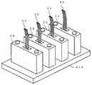
光シートバス42A、42Bは、合成樹脂製のベース部材に、図3に示す導波路部材44が光ファイバの本数と同数(例えば5個)だけ埋設されて構成されている。導波路部材44は、光透過率が高く後述するクラッド層よりも屈折率の高い材料(例えばポリメチルメタクリレート等)から成り、全体としては細長い矩形状で、幅寸法が階段状に変化している階段状部46A、46Bが中間部の2箇所に各々形成された形状とされている。導波路部材44の両端部及び階段状部46A、46Bの計4箇所には、導波路部材44の長手方向及び上下方向(図3の上下方向)に対して45°の角度で傾斜された傾斜面44A〜44Dが各々形成されている。この傾斜面44A〜44Dは信号光入出射部として機能する。導波路部材44は、導波路部材44の上面のうち個々の傾斜面44A〜44Dに対応する部分がベース部材の上面から各々露出するように埋設されており、光コネクタ24は導波路部材44のうち上記の露出部分と対向するようにベース部材に接続される。また、導波路部材44は、ベース部材の上面から露出している部分以外の外面が、導波路部材44を構成する材料よりも屈折率の低い材料(例えばフッ素ポリマ等)から成るクラッド層で被覆されている。
The optical sheet buses 42A and 42B are configured by embedding a
光シートバス42Aにおいて、第1光ファイバ26が取付けられた光コネクタ24は、導波路部材44のうち幅寸法が最大の部分に形成された傾斜面44Aに対応する露出部分と対向するようにベース部材に接続され、第2光ファイバ30、32、34が取付けられた光コネクタ24は、傾斜面44B〜44Dに対応する露出部分と対向するようにベース部材に接続される。第1光ファイバ26は光コネクタ24を介して光通信I/F部16AのLDアレイ18と接続されているので、光通信I/F部16AのLDアレイ18が発光すると、LDアレイ18の個々のLDから射出された信号光(レーザ光)は第1光ファイバ26を伝送して導波路部材44に入射し、傾斜面44Aで反射されることで導波路部材44内に閉じこめられた状態で導波路部材44内を拡散・伝播する。そして、図3(A)にも示すように、傾斜面44B〜44Dで各々反射されることで導波路部材44から射出し、光コネクタ24を介して第2光ファイバ30、32、34を伝送し光通信I/F部16B〜16DのPDアレイ20で各々受光される。
In the optical sheet bus 42A, the
また、光シートバス42Bにおいて、第1光ファイバ28が取付けられた光コネクタ24は傾斜面44Aに対応する露出部分と対向するようにベース部材に接続され、第2光ファイバ36、38、40が取付けられた光コネクタ24は、傾斜面44B〜44Dに対応する露出部分と対向するようにベース部材に接続される。第2光ファイバ36、38、40は光コネクタ24を介して光通信I/F部16B〜16DのLDアレイ18と接続されているので、光通信I/F部16B〜16Dの何れかのLDアレイ18が発光すると、該LDアレイ18の個々のLDから射出された信号光(レーザ光)は第2光ファイバ36、38、40を伝送して導波路部材44に入射し、傾斜面44B〜44Dで反射されることで導波路部材44内に閉じこめられた状態で導波路部材44内を拡散・伝播する。そして、図3(B)にも示すように、傾斜面44Aで反射されることで導波路部材44から射出し、光コネクタ24を介して第1光ファイバ28を伝送し、光通信I/F部16AのPDアレイ20で受光される。
In the optical sheet bus 42B, the
このように、光通信I/F部16AのLDアレイ18は、第1光ファイバ26、光シートバス42A及び第2光ファイバ30、32、34を介して、光通信I/F部16B〜16DのPDアレイ20と光学的に各々結合されており、光通信I/F部16B〜16DのLDアレイ18は、第2光ファイバ36、38、40、光シートバス42B及び第1光ファイバ28を介して、光通信I/F部16AのPDアレイ20と光学的に各々結合されている。
As described above, the
次に図4を参照し、光通信I/F部16A〜16Dに各々設けられた光通信制御部22の構成を説明する。光通信制御部22は、電子回路12に接続され電子回路12との通信を司る電子回路I/F部50を備えている。電子回路I/F部50は、他の電子回路12へ送信すべき情報を電子回路12から受信すると共に、他の電子回路12から受信した情報を電子回路12へ送信する。電子回路I/F部50には送信制御部52が接続されており、電子回路12から電子回路I/F部50が受信した情報(他の電子回路12へ送信すべき送信情報)は送信制御部52へ出力される。送信制御部52はフラッシュメモリ等から成る不揮発性のNVMメモリ54を内蔵しており、このNVMメモリ54には最適発光強度テーブル(詳細は後述)が記憶される。
Next, the configuration of the optical
なお、本実施の形態において、光通信I/F部16AのNVMメモリ54には、スレーブとして機能する個々の電子回路12(12B〜12D)に接続された光通信I/F部16(16B〜16D)の数、及び、該光通信I/F部16(16B〜16D)に対して予め設定されたIDが予め記憶されており、光通信I/F部16B〜16DのNVMメモリ54には自身のID及び光通信I/F部16Aに対して予め設定されたIDが予め記憶されている。上記情報は、例えばスレーブとして機能する電子回路12の増設等の電子機器10の構成変更に伴い、スレーブとして機能する電子回路12に接続された光通信I/F部16の数の増減があった場合に、オペレータ等によって書き替えられる。
In the present embodiment, the
送信制御部52には8B/10Bエンコーダ56が接続されており、送信情報は送信制御部52から1バイトずつ8B/10Bエンコーダ56へ出力される。PDアレイ20の各PDは光を受光していない状態が継続するとレスポンスが低下するという特性を有している。本実施の形態に係る光通信システム14は送信情報を光信号によってシリアルで送信するが、通常のデータには全ビットが0又は1のデータ(全ビットのデータを送信している間LDが発光しないデータ)が含まれている可能性があるので、このようなデータをシリアルで送信している間に、受信側のPDが非活性の状態となってレスポンスが低下する恐れがある。このため、8B/10Bエンコーダ56は、送信制御部52から1バイト(8ビット)ずつ入力される送信情報を、全ビットに含まれる0のビット及び1のビットの割合が一定値以下にならないように予め設定された変換条件に従い、8ビットの送信情報を10ビットの送信情報へ変換する。なお、8B/10Bエンコーダ56は実際には複数設けられており、8ビットの送信情報から10ビットの送信情報への変換は個々の8B/10Bエンコーダ56で並列に行われる。
An 8B /
8B/10Bエンコーダ56はP/S(パラレル/シリアル)変換部60を介してLD駆動部62に接続されており、8B/10Bエンコーダ56で変換された10ビットの送信情報は、P/S変換部60に入力されてシリアルのデータへ変換された後にLD駆動部62に入力される。また、8B/10Bエンコーダ56にはECC(Error-Correcting Code)生成部58が接続されており、8B/10Bエンコーダ56から出力された10ビットの送信情報はECC生成部58にも入力され、ECC生成部58によって誤り訂正のためのエラーコレクションコードが生成される。ECC生成部58もP/S変換部60を介してLD駆動部62に接続されており、ECC生成部58で生成されたエラーコレクションコードは、P/S変換部60でシリアルのデータへ変換された後にLD駆動部62に入力される。そしてLD駆動部62は、8B/10Bエンコーダ56からP/S変換部60を介して入力された送信情報及びECC生成部58からP/S変換部60を介して入力されたエラーコレクションコードに応じてLDアレイ18の個々のLDの点消灯を制御することで、送信情報を光信号として送信する。
The 8B /
また、LD駆動部62は送信制御部52と接続されており、送信制御部52からクロック信号及び発光強度制御情報が各々入力される。LDアレイ18のうちの特定のLDはクロック信号送信用とされており、LD駆動部62は入力されたクロック信号に従って特定のLDの点消灯を制御する。また、LD駆動部62はLDアレイ18の個々のLDの発光強度を制御可能とされており、入力された発光強度制御情報に従って個々のLDの発光強度を制御する。
The LD driving unit 62 is connected to the
一方、PDアレイ20には信号処理部64が接続されており、PDアレイ20の個々のPDが光信号を受信(受光)することで個々のPDから出力信号は、信号処理部64によって増幅され、デジタルの受信情報に復調されて出力される。信号処理部64はS/P(シリアル/パラレル)変換部66を介して誤り訂正部70に接続されており、信号処理部64から出力されたシリアルの受信情報はS/P変換部66によってパラレルの受信情報へ変換された後に誤り訂正部70に入力される。また、信号処理部64はS/P変換部66を介して誤り検出部68に接続されている。誤り検出部68は、信号処理部64からS/P変換部66を介して入力されるパラレルの受信情報に含まれるエラーコレクションコードに基づき、受信情報本体にビット化け等の誤り(エラー)が生じていないか否かを検証する。誤り訂正部70は誤り検出部68に接続されており、受信情報本体に誤りが生じていることが誤り検出部68によって検出された場合に受信情報本体の誤り訂正を行う。
On the other hand, a
誤り訂正部70は8B/10Bデコーダ72を介して受信制御部74に接続されており、誤り訂正を経て誤り訂正部70から出力された受信情報(本体)は、8B/10Bデコーダ72により10ビット単位で通常の8ビットのデータに変換され、受信制御部74へ入力される。また、信号処理部64は受信制御部74と接続されており、受信した光信号のうちクロック信号は受信制御部74に直接入力され、光信号送信側との同期をとるために用いられる。受信制御部74は電子回路I/F部50及び送信制御部52に各々接続されており、入力された受信情報を送信制御部52へ出力すると共に、電子回路I/F部50を介して電子回路12へ出力する。また、信号処理部64は送信制御部52にも接続されており、光信号受信(受光)時に光信号の受光量を表す受光量情報を送信制御部52へ出力する。
The
なお、光通信I/F部16Aは本発明に係る光通信装置に対応しており、光通信I/F部16AのLDアレイ18の各LDは本発明に係る第1発光素子に、光通信I/F部16AのPDアレイ20の各PDは本発明に係る第1受光素子に各々対応している。また、光通信I/F部16B〜16Dは本発明に係る第2装置に対応しており、光通信I/F部16B〜16DのLDアレイ18の各LDは本発明に係る第2発光素子に、光通信I/F部16B〜16DのPDアレイ20の各PDは本発明に係る第2受光素子に各々対応している。
The optical communication I / F unit 16A corresponds to the optical communication apparatus according to the present invention, and each LD of the
続いて、上述のように構成された本実施の形態に係わる電子機器10における通信に先だって行われる動作について説明する。なお、図5(A)は、本発明の実施の形態に係るマスタで実行される最適発光強度検出処理の流れを示すフローチャートであり、図5(B)は本発明の実施の形態に係る任意のスレーブnで実行される光信号受信時処理の流れを示すフローチャートである。
Next, operations performed prior to communication in the
本実施の形態では、電子機器10の電源投入時に、マスタとして機能する電子回路12Aに接続された光通信I/F部16Aの光通信制御部22(の送信制御部52)により、スレーブとして機能する各電子回路12に接続された光通信I/F部16へ情報を送信する際の光通信I/F部16AのLDアレイ18の各LDの最適発光強度を、個々の光通信I/F部16B〜16Cについて各々検出する最適発光強度検出処理(図5(A))が実行される。なお、送信制御部52は、最適発光強度検出処理の実行が終了すると実行終了時点からの経過時間の計測を開始し、前回実行してから所定時間以上経過した場合にも最適発光強度検出処理を行う。また、以下では光通信I/F部16Aを単に「マスタ」と称する。
In the present embodiment, when the
本実施の形態に係る最適発光強度検出処理では、まずステップ100において、NVMメモリ54を参照することで、スレーブとして機能する個々の電子回路12に接続された光通信I/F部16(以下、単に「スレーブ」と称する)の数及び個々のスレーブに予め設定されたIDを認識する。次のステップ102では、以下で処理対象とするスレーブ(便宜上、このスレーブを「スレーブn」と称する)を決定する。ステップ104では、スレーブnに対するマスタのLDアレイ18の最適発光強度がNVMメモリ54の最適発光強度テーブルに登録されているか否か判定する。判定が否定された場合には、例えばスレーブnが今回新たに増設された等の理由で、前回の最適発光強度検出処理ではスレーブnに対するマスタのLDアレイ18の最適発光強度の検出が行われていないと判断できるので、ステップ106へ移行し、スレーブnに対するマスタのLDアレイ18の最適発光強度を検出するためのLDアレイ18の各LDの発光強度の初期値及び変更範囲として所定値を設定した後にステップ112へ移行する。
In the optimum light emission intensity detection processing according to the present embodiment, first, in
一方、前回の最適発光強度検出処理で検出されたスレーブnに対するマスタのLDアレイ18の最適発光強度が最適発光強度テーブルに登録されていた場合、今回検出する最適発光強度は、最適発光強度テーブルに登録されている最適発光強度と同一又は近似した値となる可能性が高い。このため、ステップ104の判定が肯定された場合にはステップ108へ移行し、前回の最適発光強度検出処理で検出されたスレーブnに対するマスタのLDアレイ18の最適発光強度を最適発光強度テーブルから読み出し、次のステップ110では、今回検出する最適発光強度が読み出した最適発光強度と同一又は近似した値となることを前提に、読み出した最適発光強度に基づいてLDアレイ18の各LDの発光強度の初期値及び変更範囲を設定する。例えば、発光強度の変更範囲を、読み出した最適発光強度を中心としかつ通常よりも狭い範囲に設定し、発光強度の初期値を、設定した変更範囲の上限又は下限に相当する値に設定する。これにより、最適発光強度検出処理に要する時間を短縮することができる。
On the other hand, when the optimum emission intensity of the
次のステップ112では、最適発光強度検出のためにLDアレイ18の各LDを発光させる際に用いる強度検出用情報に、送信先IDとしてスレーブnのIDを、送信元IDとして自身(マスタ)のIDを各々付加すると共に、LDアレイ18の各LDの発光強度(最初は上記で設定した初期値)を表す発光強度情報を付加する。そしてステップ114では、設定した発光強度でLDアレイ18の各LDを発光させるための発光強度制御情報をLD駆動部62へ出力すると共に、スレーブn及びマスタのID、発光強度情報を付加した強度検出用情報(送信情報)を8B/10Bエンコーダ56、ECC生成部58、P/S変換部60を介してLD駆動部62へ出力する。これにより、点灯(発光)時の発光強度が設定した発光強度に一致するように、送信情報に応じてマスタのLDアレイ18の各LDが点消灯されることで、上記の送信情報に応じて変調された光信号がマスタのLDアレイ18から射出され、第1光ファイバ26、光シートバス42A、第2光ファイバ30,32,34を伝送した後に各スレーブ(光通信I/F部16B〜16D)のPDアレイ20で各々受光されることになる。なお、スレーブへ送信する情報に、スレーブのIDを送信先IDとして付加する処理は請求項11に記載の付加手段に対応している。これにより、特定のスレーブへ送信した情報が、特定のスレーブ以外のスレーブで自装置宛の情報と誤認識されることを防止することができる。
In the
次のステップ116では、スレーブnから受光状態通知を受信したか否か判定する。判定が否定された場合はステップ118へ移行し、光信号を送信してから所定時間が経過したか否か判定する。判定が否定された場合はステップ116に戻り、何れかの判定が肯定される迄、ステップ116,118を繰り返す。
In the
一方、各スレーブでは、PDアレイ20が光信号を受光し、その受光量がPDアレイ20の各PDの許容範囲内であった場合には、受光された光信号が受信情報として復調され、S/P変換部66、誤り検出部68、誤り訂正部70、8B/10Bデコーダ72を介して受信制御部74へ入力される。そして、受信情報が受信制御部74から送信制御部52へ入力されることで、送信制御部52において光信号受信時処理(図5(B)参照)が実行される。この光信号受信時処理では、まずステップ150において、受信情報に含まれている送信先IDを抽出し、抽出した送信先IDが自装置のIDか否かを判定することで、受信情報が自装置宛の情報か否か判定する。判定が否定された場合は何ら処理を行うことなく光信号受信時処理を終了する。また、判定が肯定された場合(自装置がスレーブnの場合)はステップ152へ移行し、ステップ152以降の処理を行う。
On the other hand, in each slave, when the
ここで、スレーブnにおける光信号の受光量がPDアレイ20の各PDの許容範囲外であった場合(受光量が不足していた場合)には、スレーブnの送信制御部52で上記の光信号受信時処理(図5(B))が実行されないので、マスタの送信制御部52で実行されている最適発光強度検出処理(図5(A))のステップ118の判定が肯定されてステップ120へ移行し、発光強度の設定値を所定量だけ増加設定した後にステップ112に戻る。これにより、点灯(発光)時の発光強度が所定量だけ増加するように送信情報に応じてLDアレイ18の各LDが再度点消灯されることで、同一の送信情報に応じて変調された光信号が各スレーブへ再度送信される。また、前述のステップ120の処理は、ステップ118の判定が肯定される毎に実行される。従って、スレーブnにおける光信号の受光量が不足していた場合には、スレーブnにおける光信号の受光量が許容範囲内になり、スレーブnの送信制御部52で光信号受信時処理(図5(B))が実行されるように、マスタのLDアレイ18の各LDの発光強度を所定量ずつ増大させながら光信号の送信が繰り返されることになる。
Here, when the received light amount of the optical signal in the slave n is outside the allowable range of each PD in the PD array 20 (when the received light amount is insufficient), the
また、スレーブnにおける光信号の受光量がPDアレイ20の各PDの許容範囲内であった場合には、送信制御部52で光信号受信時処理(図5(B))が実行されると共に、前述のステップ150の判定が肯定されてステップ152へ移行し、受信情報が強度検出用情報か否かを判断することで、自装置に対する最適発光強度の検出がマスタで実行中か否か判定する。判定が否定された場合はステップ158へ移行し、受信情報が最適発光強度を通知する情報か否かを判定する。この判定も否定された場合はステップ162へ移行し、受信情報の内容に応じた処理を実行して光信号受信時処理を終了する。
When the received light amount of the optical signal in the slave n is within the allowable range of each PD of the
また、ステップ152の判定が肯定された場合はステップ154へ移行し、信号処理部64から入力される受光量情報に基づいて、PDアレイ20の各PDによる光信号の受光状態を表す受光状態情報を生成する。なお、受光状態情報としては、例えばPDアレイ20の各PDの受光量の許容範囲の下限値とPDアレイ20の各PDによる光信号の実際の受光量の偏差を表す情報を適用することができるが、これに代えて、PDアレイ20の各PDの受光量の許容範囲の上限値とPDアレイ20の各PDによる光信号の実際の受光量の偏差を表す情報を適用してもよいし、PDアレイ20の各PDの受光量の許容範囲の上限値及び下限値、PDアレイ20の各PDによる光信号の実際の受光量を各々表す情報を適用してもよい。
On the other hand, if the determination in step 152 is affirmative, the process proceeds to step 154, and the light reception state information indicating the light reception state of the optical signal by each PD of the
そしてステップ156では、受信情報から発光強度情報を抽出し、抽出した発光強度情報を生成した受光状態情報に付加すると共に、送信先IDとしてマスタのIDを、送信元IDとして自装置のIDを各々付加した後に、予め設定された発光強度(これに代えて前回検出した最適発光強度を適用してもよい)でLDアレイ18の各LDを発光させるための発光強度制御情報をLD駆動部62へ出力すると共に、発光強度情報を付加した受光状態情報を8B/10Bエンコーダ56、ECC生成部58、P/S変換部60を介してLD駆動部62へ出力し、光信号受信時処理を終了する。これにより、点灯(発光)時の発光強度が設定した発光強度に一致するように、上記の受信状態情報に応じてスレーブnのLDアレイ18の各LDが点消灯されることで、上記の受信状態情報に応じて変調された光信号がスレーブnのLDアレイ18から射出され、第2光ファイバ36、38、40の何れか、光シートバス42B、第1光ファイバ28を伝送した後にマスタのPDアレイ20で受光されることになる。
In
マスタでは、スレーブnから発光強度情報を付加した受光状態情報を受信すると、最適発光強度検出処理(図5(A))のステップ116の判定が肯定されてステップ122へ移行し、受信した受光状態情報を参照することで、該受光状態情報に付加されている発光強度情報が表す発光強度が、スレーブnへ情報を送信する際のLDアレイ18の各LDの最適発光強度か否か判定する。この最適発光強度としては、例えばスレーブnのPDアレイ20の各PDの受光量が受光量の許容範囲の下限値に一致する最適状態となる発光強度を適用することができる。このように最適状態となる発光強度を適用することで、マスタのLDアレイ18を最大限に長寿命化できると共に、発熱量を必要最小限に抑制できる。また、受信した受光状態情報が表す受光量が上記の最適状態に相当する受光量と相違していた場合には、ステップ122の判定が否定されてステップ124へ移行し、受光状態情報によって通知されたスレーブnのPDアレイ20の各PDの受光状態に応じて発光強度を変更設定した後にステップ112に戻る。
When the master receives light reception state information to which light emission intensity information is added from slave n, the determination in
これにより、点灯(発光)時の発光強度が変更設定後の発光強度に一致するように前回と同一の情報に応じてLDアレイ18の各LDが再度点消灯され、前回と同一の情報に応じて変調された光信号が前回とは異なる発光強度で各スレーブへ再度送信される。従って、スレーブnにおける光信号の受光量が最適状態に相当する受光量と相違していた場合には、スレーブnにおける光信号の受光量が最適状態になるように、スレーブnのPDアレイ20の各PDの受光状態に応じてマスタのLDアレイ18の各LDの発光強度を変更設定しながら光信号の送信が繰り返されることになる。
Thereby, each LD of the
スレーブnのPDアレイ20の各PDの受光量が最適状態に相当する受光量に一致すると、ステップ122の判定が肯定されてステップ126へ移行し、現在の発光強度(最後に受信した受光状態情報に付加されていた発光強度情報が表す発光強度)を、スレーブnに対するマスタのLDアレイ18の最適発光強度として、スレーブnのIDと対応付けてNVMメモリ54の最適発光強度テーブルに登録する。このように、処理対象のスレーブnへ送信する強度検出用情報に発光強度情報を付加し、スレーブnから受信した受光状態情報に付加されている発光強度情報に基づいて、最適発光強度(スレーブnにおける光信号の受光量が最適状態になるときのマスタのLDアレイ18の発光強度)を認識する処理を行うことにより、最適発光強度を確実に認識することができる。
When the received light amount of each PD in the
次のステップ128では、スレーブnに対して上記の最適発光強度を通知する情報を生成し、生成した情報に送信先IDとしてスレーブnのIDを、送信元IDとして自身(マスタ)のIDを各々付加して光通信により送信する。これにより、スレーブnの送信制御部52で実行される光信号受信時処理(図5(B))では、ステップ150の判定が肯定され、ステップ152の判定が否定され、ステップ158の判定が肯定されてステップ160へ移行し、マスタから通知されたスレーブnに対するマスタのLDアレイ18の最適発光強度がスレーブnのNVMメモリ54に記憶される。
In the next step 128, information for notifying the slave n of the optimum light emission intensity is generated, and the ID of the slave n as the transmission destination ID and the own (master) ID as the transmission source ID are generated in the generated information. In addition, it transmits by optical communication. Thereby, in the optical signal reception process (FIG. 5B) executed by the
また、マスタで実行されている最適発光強度検出処理(図5(A))では、次のステップ130において、上述したステップ102以降の処理を全てのスレーブに対して行ったか否か判定する。判定が否定された場合はステップ102に戻り、新たなスレーブを処理対象としてステップ102の処理を繰り返す。これにより、全てのスレーブに対してマスタのLDアレイ18の最適発光強度が各々検出され、検出された最適発光強度がNVMメモリ54の最適発光強度テーブルに各々登録されると共に、対応するスレーブnに通知されることになる。
In the optimum emission intensity detection process (FIG. 5A) executed by the master, in the next step 130, it is determined whether or not the processes after
ステップ130の判定が肯定されて最適発光強度検出処理(図5(A))が終了すると、マスタの送信制御部52は、個々のスレーブに対し、マスタへ情報を送信する際の個々のスレーブのLDアレイ18の各LDの最適発光強度を検出する処理の実行を指示する所定の情報を、光通信によって順に送信する。これにより、前記所定の情報を受信することで最適発光強度を検出する処理の実行が指示されたスレーブ(便宜上「スレーブn」と称する)では、送信制御部52で最適発光強度検出処理(図6(A))が実行される。なお、図6(A)は、任意のスレーブnで実行される最適発光強度検出処理の流れを示すフローチャートであり、(B)はマスタで実行される光信号受信時処理の流れを示すフローチャートである。
When the determination in step 130 is affirmed and the optimum emission intensity detection process (FIG. 5A) is completed, the master
この最適発光強度検出処理では、まずステップ180において、マスタから通知されてNVMメモリ54に記憶させた最適発光強度(スレーブnに対するマスタのLDアレイ18の最適発光強度)を読み出す。本実施の形態では、マスタによる各スレーブへの情報の送信に用いられる光伝送路(第1光ファイバ26、光シートバス42A及び第2光ファイバ30、32、34)と、各スレーブによるマスタへの情報の送信に用いられる光伝送路(第1光ファイバ28、光シートバス42B及び第2光ファイバ36、38、40)が相違しているものの、光伝送路の距離は略等しいので、スレーブnがマスタへ情報を送信する際の最適発光強度は、マスタがスレーブnへ情報を送信する際の最適発光強度と同一又は近似した値となる可能性が高い。
In the optimum emission intensity detection process, first, in step 180, the optimum emission intensity notified from the master and stored in the NVM memory 54 (the optimum emission intensity of the
上記に基づきステップ182では、今回検出する最適発光強度がNVMメモリ54から読み出した最適発光強度(マスタで検出されて通知された、スレーブnに対するマスタのLDアレイ18の最適発光強度)と同一又は近似した値となることを前提に、読み出した最適発光強度に基づいてスレーブnのLDアレイ18の各LDの発光強度の初期値及び変更範囲を設定する。これにより、最適発光強度検出処理に要する時間を短縮することができる。次のステップ184では、最適発光強度検出のためにLDアレイ18の各LDを発光させる際に用いる強度検出用情報に、送信先IDとしてマスタのIDを、送信元IDとして自装置(スレーブn)のIDを各々付加すると共に、スレーブnのLDアレイ18の各LDの発光強度を表す発光強度情報を付加する。
Based on the above, in step 182, the optimum emission intensity detected this time is the same as or approximate to the optimum emission intensity read from the NVM memory 54 (the optimum emission intensity of the
そしてステップ186では、設定した発光強度でLDアレイ18の各LDを発光させるための発光強度制御情報をLD駆動部62へ出力すると共に、マスタ及び自装置のID、発光強度情報を付加した強度検出用情報(送信情報)を8B/10Bエンコーダ56、ECC生成部58、P/S変換部60を介してLD駆動部62へ出力する。これにより、点灯(発光)時の発光強度が設定した発光強度に一致するように、送信情報に応じてスレーブnのLDアレイ18の各LDが点消灯されることで、上記の送信情報に応じて変調された光信号がスレーブnからマスタへ送信され、第2光ファイバ36,38,40の何れか、光シートバス42B、第1光ファイバ28を伝送した後にマスタのPDアレイ20で受光される。
In step 186, the emission intensity control information for causing each LD of the
次のステップ188では、マスタから受光状態通知を受信したか否か判定する。判定が否定された場合はステップ190へ移行し、光信号を送信してから所定時間が経過したか否か判定する。判定が否定された場合はステップ188に戻り、何れかの判定が肯定される迄、ステップ188,190を繰り返す。 In the next step 188, it is determined whether or not a light reception state notification is received from the master. When determination is denied, it transfers to step 190, and it is determined whether predetermined time passed since transmitting the optical signal. If the determination is negative, the process returns to step 188, and steps 188 and 190 are repeated until either determination is positive.
マスタでは、各スレーブの何れかから光信号を受信する毎に、送信制御部52で光信号受信時処理(図6(B)参照)が実行される。この光信号受信時処理では、まずステップ210において、受信情報に含まれている送信先IDを抽出し、抽出した送信先IDが自装置のIDか否かを判定することで、受信情報が自装置宛の情報か否か判定する。判定が否定された場合は何ら処理を行うことなく光信号受信時処理を終了する。なお、本第1実施形態の構成では、各スレーブが送信する情報は何れもマスタ宛の情報であり、ステップ210の判定が否定されることはないので、ステップ210を省略してもよい。また、判定が肯定された場合はステップ212へ移行し、ステップ212以降の処理を行う。
In the master, every time an optical signal is received from any one of the slaves, the
ここで、マスタにおける光信号の受光量がPDアレイ20の各PDの許容範囲外であった場合(受光量が不足していた場合)には、マスタの送信制御部52で上記の光信号受信時処理(図6(B))が実行されないので、スレーブnの送信制御部52で実行されている最適発光強度検出処理(図6(A))のステップ188の判定が肯定されてステップ190へ移行し、発光強度の設定値を所定量だけ増加設定した後にステップ184に戻る。これにより、点灯(発光)時の発光強度が所定量だけ増加するように送信情報に応じてLDアレイ18の各LDが再度点消灯されることで、同一の送信情報に応じて変調された光信号がマスタへ再度送信される。従って、マスタにおける光信号の受光量が不足していた場合には、マスタにおける光信号の受光量が許容範囲内になるように、LDアレイ18の各LDの発光強度を所定量ずつ増大させながら光信号の送信が繰り返される。
Here, when the received light amount of the optical signal at the master is out of the allowable range of each PD of the PD array 20 (when the received light amount is insufficient), the
また、マスタにおける光信号の受光量がPDアレイ20の各PDの許容範囲内であった場合には、マスタの送信制御部52で光信号受信時処理(図6(B))が実行されると共に、前述のステップ210の判定が肯定されてステップ212へ移行し、受信情報が強度検出用情報か否かを判断することで、自装置に対する最適発光強度の検出がスレーブnで実行中か否か判定する。判定が否定された場合はステップ214へ移行し、受信情報の内容に応じた処理を実行して光信号受信時処理を終了する。
If the received light amount of the optical signal in the master is within the allowable range of each PD of the
また、ステップ212の判定が肯定された場合はステップ216へ移行し、信号処理部64から入力される受光量情報に基づいて、PDアレイ20の各PDによる光信号の受光状態を表す受光状態情報を生成する。そしてステップ218では、受信情報から発光強度情報を抽出し、抽出した発光強度情報を生成した受光状態情報に付加すると共に、送信先IDとしてスレーブnのIDを、送信元IDとして自装置(マスタ)のIDを各々付加した後に、先に検出して最適発光強度テーブルに登録されているスレーブnに対する最適発光強度でLDアレイ18の各LDを発光させるための発光強度制御情報をLD駆動部62へ出力すると共に、発光強度情報を付加した受光状態情報(送信情報)を8B/10Bエンコーダ56、ECC生成部58、P/S変換部60を介してLD駆動部62へ出力し、光信号受信時処理を終了する。これにより、スレーブn及びマスタのID、発光強度情報が付加された受光状態情報が、マスタから光通信によってスレーブnへ送信される。
If the determination in
スレーブnでは、マスタから発光強度情報が付加された受光状態情報を受信すると、最適発光強度検出処理(図6(A))のステップ188の判定が肯定されてステップ194へ移行し、受信した受光状態情報を参照することで、該受光状態情報に付加されている発光強度情報が表す発光強度が、マスタへ情報を送信する際のLDアレイ18の各LDの最適発光強度か否か判定する。判定が否定された場合はステップ196へ移行し、受光状態情報によって通知されたマスタのPDアレイ20の各PDの受光状態に応じて発光強度を変更設定した後にステップ184に戻る。 これにより、マスタにおける光信号の受光量が最適状態になるように、マスタのPDアレイ20の各PDの受光状態に応じてスレーブnのLDアレイ18の各LDの発光強度を変更設定しながら光信号の送信が繰り返されることになる。
When the slave n receives the light reception state information to which the light emission intensity information is added from the master, the determination in step 188 of the optimum light emission intensity detection process (FIG. 6A) is affirmed, and the process proceeds to step 194. By referring to the state information, it is determined whether or not the light emission intensity represented by the light emission intensity information added to the light reception state information is the optimum light emission intensity of each LD of the
マスタのPDアレイ20の各PDの受光量が最適状態に相当する受光量に一致すると、ステップ194の判定が肯定されてステップ198へ移行し、現在の発光強度(最後に受信した受光状態情報に付加されていた発光強度情報が表す発光強度)を、マスタに対するスレーブnのLDアレイ18の最適発光強度としてNVMメモリ54に記憶させ、最適発光強度検出処理を終了する。なお、上述した最適発光強度検出処理は、マスタからの指示により各スレーブで順次実行される。
When the received light amount of each PD in the
以上のようにしてマスタ及び各スレーブで光通信の相手に対する最適発光強度の検出が完了すると、通常の光通信が行われるが、この通常の光通信において、マスタが任意のスレーブに情報を送信する場合、マスタの送信制御部52は、情報送信対象のスレーブのIDと対応付けてNVMメモリ54の最適発光強度テーブルに登録されている最適発光強度を読み出し、読み出した最適発光強度でLDアレイ18の各LDを発光させるための発光強度制御情報をLD駆動部62へ出力する。すなわち、マスタの送信制御部52は本発明の設定手段として機能する。
As described above, when the master and each slave complete the detection of the optimum light emission intensity for the other party of optical communication, normal optical communication is performed. In this normal optical communication, the master transmits information to an arbitrary slave. In this case, the master
また、任意のスレーブ(スレーブn)がマスタに情報を送信する場合、スレーブnの送信制御部52は、NVMメモリ54に記憶されている最適発光強度(マスタに対するスレーブnのLD18の最適発光強度)を読み出し、読み出した最適発光強度でLDアレイ18の各LDを発光させるための発光強度制御情報をLD駆動部62へ出力する。これにより、任意のスレーブnからマスタへの情報の送信に際しても、マスタにおける光信号の受光量が最適状態になるように、スレーブnのLDアレイ18の各LDの発光強度が制御される。
When an arbitrary slave (slave n) transmits information to the master, the
このように、本発明の実施の形態では、各スレーブに対するマスタのLDアレイ18の最適発光強度がマスタによって検出され、マスタは任意のスレーブへ情報を送信する際にLDアレイ18の各LDの発光強度が情報送信先のスレーブに対応する最適発光強度となるように制御するので、光通信によって個々のスレーブへ確実に情報を送信することができると共に、LDアレイ18の発光強度が個々のスレーブ毎に最適化されるので、マスタのLDアレイ18が必要以上の発光強度で発光されることでLDアレイ18の寿命に悪影響を及ぼしたり、LDアレイ18が必要以上に発熱することを防止することができる。
Thus, in the embodiment of the present invention, the optimum light emission intensity of the
ところで、上述のように構成された光通信システム14において、図7に示すように、光シートバス42から各スレーブ16a〜16dまでの伝送距離が異なる場合には、上述したように光ファイバとしてPOFを適用しているので、伝送距離が異なることによって、各スレーブにおける光損失がそれぞれ異なることになる。
By the way, in the
一般的には、マスタ16Aは、最長距離(光損失大)に伝送できるように光強度を上げればそれ以外の光損失の小さい伝送距離の短いスレーブにも必然的に伝送できることになるが、光量増によって発光素子の寿命が短くなることや発熱が多くなる問題があり、必ずしも適切な方法とは言えないのは上述したとおりであり、本実施の形態では、上述のように伝送したいスレーブにだけ最小受光量以上で届くように随時光強度を切り換えるようになっている。詳細には上述した通りであり、各スレーブ毎に最適発光強度を決定した後に、スレーブに対応する各電子回路に対して通常の通信を行う際には、各スレーブに応じて最適発光強度を切り換えて、伝送先のスレーブに対応するIDを情報に付加して情報を送信する。 In general, if the light intensity is increased so that the master 16A can transmit the longest distance (high light loss), the master 16A can inevitably transmit to other slaves having a small transmission distance with a small light loss. There is a problem that the lifetime of the light emitting element is shortened due to the increase and heat generation is increased, and it is not necessarily an appropriate method as described above. In this embodiment, only the slave to be transmitted as described above is used. The light intensity is switched from time to time so that it reaches the minimum received light amount or more. The details are as described above, and after determining the optimum emission intensity for each slave, when performing normal communication to each electronic circuit corresponding to the slave, the optimum emission intensity is switched according to each slave. Then, the ID corresponding to the transmission destination slave is added to the information and the information is transmitted.
しかしながら、上述したように、PDアレイ20の各PDは光を受光していない状態が継続するとレスポンスが低下するという特性を有しているので、あるスレーブと通信を行っている時に、現在通信中のスレーブよりも光損失が大きい(伝送距離の長い)スレーブでは、PDアレイ20に光が届いていないことがあり得る。例えば、図7のスレーブ16aから次のスレーブ16bに通信を切り換える場合には、スレーブ16bのPDアレイ20に光が届いてないことがある。この場合に、次のスレーブと通信を行うためには、PDアレイ20が活性化していないために、レスポンスが悪くなってしまう、という問題が発生する。このようにレスポンスが悪い状態で通信を行うことで、誤通信などの弊害を引き起こすことも考えられる。
However, as described above, each PD of the
そこで、本実施の形態では、通常の通信時に伝送先のスレーブを切り換える際に、PDアレイ20の非活性によって発生するレスポンスの低下を防止するためにマスタ16Aが伝送先のスレーブを活性化するための活性化処理を行うようになっている。
Therefore, in the present embodiment, when switching the transmission destination slave during normal communication, the master 16A activates the transmission destination slave in order to prevent a decrease in response caused by the inactivation of the
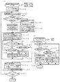
次に、マスタ16Aによって行われる活性化処理について説明する。図8は、マスタ16Aで行われる活性化処理の流れの一例を示すフローチャートである。なお、本実施の形態では、マスタ16Aで行う活性化処理は、現在のスレーブから次のスレーブに切り換える際、すなわち伝送先スレーブを切り換える毎に、現在のスレーブへの通信が終了した時点で行う処理として説明する。また、マスタ16Aで行われる活性化処理は本発明の活性化手段に対応する。 Next, the activation process performed by the master 16A will be described. FIG. 8 is a flowchart showing an example of the flow of activation processing performed by the master 16A. In the present embodiment, the activation process performed by the master 16A is a process performed when communication with the current slave is completed when switching from the current slave to the next slave, that is, whenever the transmission destination slave is switched. Will be described. The activation process performed by the master 16A corresponds to the activation means of the present invention.
本実施の形態では、上述のようにして最適光強度が決定されて通常の通信に移行すると、各スレーブを切り換える際に活性化処理を行うことで、各スレーブのPDアレイ20に光が届いていない場合にPDの活性化を行う。PDの活性化は、次のスレーブに対応する最適光強度に設定し、例えば、周波数変調したIDを付与しない擬似パターンを送信することで行われる。
In the present embodiment, when the optimum light intensity is determined as described above and a transition is made to normal communication, light is delivered to the
詳細には、本実施の形態に係わるマスタ16Aで行われる活性化処理では、まずステップ300において、スレーブExx(便宜上、次伝送先のスレーブを「スレーブExx」と称する)へ伝送するか否か判定する。判定が否定された場合には、そのまま活性化処理を終了して通常の通信を継続する。
Specifically, in the activation process performed by the master 16A according to the present embodiment, first, in
現在のスレーブから切り換えてスレーブExxへ伝送する場合には、ステップ300の判定が肯定されてステップ302へ移行し、NVMメモリ54を参照して、最適光強度テーブルから対応するスレーブの最適光強度を読み出して、ステップ304へ移行する。そして、読み出さした次のスレーブExxのLD駆動62の発光強度設定を最適光強度に設定した後にステップ306へ移行する。
When switching from the current slave and transmitting to the slave Exx, the determination in
次にステップ306では、直前の伝送先の光強度より次の伝送先の光強度の方が小さいか否か判定する。すなわち、NVMメモリ54を参照して直前の伝送先のスレーブの最適光強度と次の伝送先スレーブの最適光強度を比較することによって判定を行う。判定が否定された場合には、ステップ308へ移行して、擬似パターンの送信開始処理を行う。
Next, in
擬似パターンの送信開始処理では、スレーブExxに対応する最適光強度の擬似パターンで発光させるための発光制御情報をLD駆動部62へ出力する。これによって、予め定められた擬似パターンでLDアレイ18の各LDが発光し、スレーブ側のPDアレイ20が活性化される。なお、スレーブ側のPDアレイ20の活性化は、クロック信号等の周波数を変調して調整した信号を適用することが可能である。また、擬似パターンや周波数を変調して調整した信号は、、DCバランスのとれた信号を送信する。
In the pseudo-pattern transmission start process, the emission control information for causing the pseudo-pattern with the optimum light intensity corresponding to the slave Exx to emit light is output to the LD driving unit 62. As a result, each LD of the
そして、ステップ310では、所定時間経過したか否か判定する。すなわち、所定時間活性化を行った後に、ステップ312へ移行して、次のスレーブExxへの情報送信を開始して、一連の活性化処理を終了する。すなわち、活性化を行っている間は通信を待機し、活性化が終了した時点で通信を開始するので、活性化される前に通信を行うことによる誤通信を防止することができる。 In step 310, it is determined whether a predetermined time has elapsed. That is, after activation for a predetermined time, the process proceeds to step 312 to start transmission of information to the next slave Exx, and a series of activation processes is completed. That is, communication is waited during activation, and communication is started when activation is completed. Therefore, erroneous communication due to communication before activation can be prevented.
一方、ステップ306の判定が肯定、すなわち、直前の伝送先のスレーブの光強度より小さい場合には、現在のスレーブへの通信時の光強度によって次のスレーブのPDアレイ20が活性化されているので、擬似パターンの送信を行わずにそのままステップ312へ移行して、次のスレーブExxへの情報送信を開始して、一連の活性化処理を終了する。なお、ステップ306が肯定されてステップ312へ移行する処理は本発明の活性化制御手段に対応する。
On the other hand, if the determination in
また、ステップ312で次のスレーブExxへ情報送信が開始されると、スレーブ側では、上述した光信号受信時処理(図5(B))が行われる。すなわち、自装置宛と認識したスレーブは、ステップ150が肯定され、この場合には、強度検出ではなく、最適発光強度通知ではないので、ステップ152及びステップ158が否定されて、受信情報に応じた処理が実行される。すなわち、情報を受信する処理が実行され、マスタから送信される情報が受信され、後段に接続される電子回路12B〜12Dにスレーブが受信した情報が出力される。この時、上述したように活性化処理によってPDアレイ20が活性化されているので、マスタから送信される情報を確実に受信することができる。
Further, when information transmission to the next slave Exx is started in step 312, the above-described optical signal reception process (FIG. 5B) is performed on the slave side. That is, for the slave recognized as addressed to its own device, step 150 is affirmed, and in this case, not the intensity detection but the optimum light emission intensity notification, so step 152 and step 158 are denied, and according to the received information Processing is executed. That is, a process of receiving information is executed, information transmitted from the master is received, and information received by the slave is output to the electronic circuits 12B to 12D connected to the subsequent stage. At this time, as described above, since the
ここで、上述のようにして行われる活性化処理について、図7の場合を例に挙げて具体的に説明する。 Here, the activation process performed as described above will be specifically described by taking the case of FIG. 7 as an example.
図7において、マスタ16Aがスレーブ16a、16b、16c、16dの順番に信号を伝送しようとしたとする。マスタ16Aは、スレーブ16aに信号を伝送している時に、マスタ16AのLDアレイの光強度は、スレーブ16aが最も光損失が少ないので、最小の光強度となり、スレーブ16b、16c、16dには、PDアレイ20を活性化させるために必要な光が十分に届いてない場合ある。この状態では、スレーブ16aからスレーブ16bに伝送先を切り換えて直ぐに信号を送信できないので、マスタ16Aは、まずLDアレイ18の光強度をスレーブ16bの光強度に切り換える(ステップ300〜304)。そして、ステップ308において、直流(DC)バランスのとれた擬似パターンもしくはクロックなどの一定の周波数を送信してスレーブ16bのPDアレイ20が受信し得る状態になるまでの一定時間活性化させ、ステップ310でマスタ16Aはデータを電送しない待ち状態となる。その後、一定時間経過後にステップ310の判定が肯定されて、ステップ312へ移行して、マスタ16Aはスレーブ16bに光信号を伝送し始める。このように、光信号を送信する前に、非活性であったPDアレイ20を擬似パターン等で活性化させてから光信号を伝送することで、誤通信などの弊害を防止することができる。
In FIG. 7, it is assumed that the master 16A tries to transmit signals in the order of the
また、スレーブ16bからスレーブ16cに切り換えを行う場合も同様に処理が行われる。スレーブ16cからスレーブ16dに切り換える場合には、伝送確立の際に既に最適光強度が決定されていることからスレーブ16dはスレーブ16cよりも光強度は小さくて済むことがわかっている。そこで、ステップ306の判定が肯定されてステップ312へ移行して、マスタ16Aは瞬時に光信号をスレーブ16dに伝送を始めることができる。
The same processing is performed when switching from the slave 16b to the
このように、本実施の形態では、スレーブの切り換えの際に、光が十分に届いていないと判断される場合に活性化処理を行なうようにしたので、伝送経路がそれぞれ異なるスレーブが接続されている場合であっても、誤通信などの弊害を起こすことなく通信を行うことができる。 As described above, in this embodiment, when the slave is switched, the activation process is performed when it is determined that the light does not reach sufficiently. Therefore, slaves having different transmission paths are connected. Even if it is, communication can be performed without causing adverse effects such as erroneous communication.
続いて、上述の活性化処理の変形例について説明する。上記の実施の形態では、擬似パターン等の通信信号とは関係のない信号をスレーブの切り換え時に送信して活性化を行なう例を説明したが、変形例では、次に切り換えるスレーブの光強度が大きい場合に、切り換える前に次の光強度に切り換えて、現在の通信時に次のスレーブのPDアレイ20を活性化させるものであり、切り換え時間を短縮させることができる。
Subsequently, a modification of the above-described activation process will be described. In the above-described embodiment, an example in which activation is performed by transmitting a signal not related to a communication signal such as a pseudo pattern at the time of switching of the slave has been described. However, in the modification, the light intensity of the slave to be switched next is high. In this case, the light intensity is switched to the next light intensity before switching, and the
図9は、マスタ16Aによって行なわれる活性化処理の変形例の流れを示すフローチャートである。なお、変形例では、現在のスレーブへの通信が終了する前に行われる処理として説明する。 FIG. 9 is a flowchart showing a flow of a modification of the activation process performed by the master 16A. In the modified example, the process is described as being performed before communication with the current slave is completed.
まずステップ350において、次のスレーブExxへ伝送準備か否か判定する。判定が否定された場合には、そのまま活性化処理を終了して通常の通信を継続する。なお、ステップ350の判定は、現在のスレーブから次のスレーブに切り換える前に行われ、現在のスレーブの通信が終了する所定時間前(PDアレイ20を活性化させるために必要な時間から定めることが可能である時間)である時に判定が肯定される。
First, in
現在のスレーブから切り換えて次伝送先のスレーブExxへ伝送する場合には、ステップ350の判定が肯定されてステップ352へ移行し、NVMメモリ54を参照して、最適光強度テーブルから対応するスレーブの最適光強度を読み出して、ステップ354へ移行する。そして、読み出した次のスレーブExxのLD駆動部62の最適光強度を確認した後にステップ356へ移行する。
When switching from the current slave and transmitting to the next transmission destination slave Exx, the determination in
次にステップ356では、現在通信中の光強度より次の伝送先の光強度の方が小さいか否か判定する。すなわち、NVMメモリ54を参照して現在のスレーブの最適光強度と次伝送先スレーブの最適光強度を比較することによって判定を行う。判定が否定された場合には、ステップ358へ移行して、現在の通信を行いながら、次のスレーブExxの最適光強度となるように光強度を徐々に増加させ、一連の活性化処理を終了する。このように、伝送中の光強度より次の光強度の方が大きい場合には、現在の通信中に次のスレーブへ十分な光が届いてないことが考えられるので、現在の通信中に徐々に次のスレーブの最適光強度となるように徐々に光強度を増加させることで、次のスレーブのPDアレイ20が活性化され、直ぐにスレーブを切り換えて通信を行うことが可能となる。
Next, in step 356, it is determined whether the light intensity of the next transmission destination is smaller than the light intensity currently being communicated. That is, the determination is performed by referring to the
一方、現在の通信中の光強度より次伝送先のスレーブへの光強度の方が小さい場合には、十分に次伝送先のスレーブのPDアレイ20が活性化されているので、ステップ356の判定が肯定されてステップ360へ移行して、光強度の変更を行わずに、現在の光強度での通信を継続し、一連の活性化処理を終了する。
On the other hand, if the light intensity to the slave at the next transmission destination is smaller than the light intensity during the current communication, the
なお、変形例の活性化処理が終了した時点で、次伝送先のスレーブの光強度の方が小さい場合には、光強度の変更が行われていないので、次伝送先のスレーブへ通信を切り換える際に光強度を次伝送先のスレーブの最適光強度となるように光強度を減少させる方が、LD寿命の面から好ましい。 If the light intensity of the slave at the next transmission destination is smaller at the time when the activation process of the modification is completed, the light intensity has not been changed, so the communication is switched to the slave at the next transmission destination. At this time, it is preferable from the viewpoint of the LD lifetime that the light intensity is reduced so that it becomes the optimum light intensity of the slave of the next transmission destination.
このように、変形例では、現在のスレーブへの通信が終了する前に、次のスレーブのPDアレイ20が活性化されていないと判断される場合には、現在のスレーブの通信中に光強度を増加させることで、次伝送先のスレーブのPDアレイ20を活性化させるので、スレーブを切り換えて直ぐに通信を行うことができる。また、上記の実施の形態のように現在の通信が終了した時点で次のスレーブのPDアレイ20を活性化させるのではなく、現在の通信中に次伝送先のスレーブのPDアレイ20を活性化させるので、スレーブの切り換え時間を短縮することができる。
As described above, in the modified example, when it is determined that the
なお、上記の実施の形態では、スレーブで行われる光信号受信時処理の際にまず最初にステップ150で自装置宛であるか否かを判定するようにしたが、光強度が弱い場合に自装置宛か否かを誤判断する可能性があるので、まず始めに光強度が最低受光量以下か否かを判断して、最低受光量以下の場合には、信号とみなさない判断手段を設けるようにしてもよい。すなわち、図10に示すフローチャートのように、ステップ150に先だって、ステップ148において、最低受光量以下か否かを判定するようにしてもよい。該判定が肯定された場合には、そのまま光信号受信時処理を終了することで、光強度が弱い場合に信号とみなさない処理を追加することができる。すなわち、上記判断手段を設けることが可能となり、当該ステップ148が本発明の判断手段に対応し、判断手段を設けることで弱い信号を誤検出するを防止することができる。 In the above embodiment, at the time of optical signal reception processing performed by the slave, it is first determined in step 150 whether or not it is addressed to the own device. Since there is a possibility of misjudging whether or not it is destined for the device, it is first determined whether or not the light intensity is less than the minimum received light amount. You may do it. That is, as in the flowchart shown in FIG. 10, prior to step 150, it may be determined in step 148 whether or not it is equal to or less than the minimum received light amount. If the determination is affirmative, the processing at the time of receiving an optical signal is terminated as it is, thereby adding processing that is not regarded as a signal when the light intensity is weak. That is, it is possible to provide the determination means, and the step 148 corresponds to the determination means of the present invention. By providing the determination means, it is possible to prevent erroneous detection of a weak signal.
また、マスタにおける光信号受信時処理においても同様に判断手段を設けるようにしてもよい。 Similarly, a determination unit may be provided in the optical signal reception process in the master.
さらに、上記の実施の形態では、電子機器10の一例としてフルカラープリンタを例に挙げたが、本発明はこれに限定されるものではなく、例えばコンピュータ等の任意の電子機器を適用可能であることは言うまでもない。
Furthermore, in the above-described embodiment, a full-color printer is taken as an example of the
10 電子機器
14 光通信システム
16 光通信I/F部
18 LDアレイ
20 PDアレイ
22 光通信制御部
26、28、30、32、34、36、38、40 光ファイバ
42 光シートバス
52 送信制御部
DESCRIPTION OF
Claims (5)
前記第1発光素子の発光強度を前記複数の第2装置毎に記憶する記憶手段と、
予め前記複数の第2装置の各々に対して、前記第1発光素子の発光強度を所定量ずつ増大させながら光信号の送信を繰り返すことによって、前記複数の第2装置の各々が受光できた際の、前記第1発光素子の発光強度を、前記複数の第2装置毎に前記記憶手段に登録する登録手段と、
前記記憶手段に記憶された発光強度で前記第2装置へ前記情報を送信し、前記登録手段により前記記憶手段に登録された、次伝送先の第2装置に対する前記第1発光素子の発光強度を読取り、該次伝送先の第2装置に対する前記第1発光素子の発光強度よりも前記現伝送先の第2装置に対する前記第1発光素子の発光強度の方が小さい場合には、現伝送先の第2装置の第2受光素子に対して前記情報を送信している間に、前記第1発光素子の発光強度を次伝送先の第2装置に対する前記第1発光素子の発光強度となるように光強度を増加することで、次伝送先の第2装置の第2受光素子を受信可能な状態に活性化する活性化手段と、
を備えることを特徴とする光通信装置。 The distributed optical signal transmission body is connected to a plurality of second devices via different second optical fibers, and is connected to arbitrary information via a first optical fiber. In response, the light emitted from the first light emitting element is transmitted to the plurality of second devices via the first optical fiber, the distributed optical signal transmission body, and the second optical fiber, respectively, An optical communication device capable of transmitting arbitrary information to each of the plurality of second devices by optical communication by receiving light with a second light receiving element provided in each of the second devices,
Storage means for storing emission intensity of the first light emitting element for each of the plurality of second devices;
When each of the plurality of second devices has received light by repeating transmission of an optical signal to each of the plurality of second devices in advance while increasing the light emission intensity of the first light emitting element by a predetermined amount. Registration means for registering the emission intensity of the first light emitting element in the storage means for each of the plurality of second devices;
The information is transmitted to the second device with the light emission intensity stored in the storage means, and the light emission intensity of the first light emitting element with respect to the second device of the next transmission destination registered in the storage means by the registration means. reading, when the direction of emission intensity of the first light emitting element to the second device of the current transmission destination than the emission intensity of the first light emitting element to the second device said next destination is small, the current destination while sending the information to the second light receiving element of the second device, the emission intensity of the first light emitting element such that the emission intensity of the first light emitting element to the second device follows the transmission destination Activating means for activating the second light receiving element of the second device of the next transmission destination so as to be receivable by increasing the light intensity;
An optical communication device comprising:
第1光ファイバを介して分配型光信号伝送体と接続されると共に、前記分配型光信号伝送体が各々異なる第2光ファイバを介して複数の第2装置と各々接続され、
前記記憶手段には、予め、前記複数の第2装置の各々に対して、前記第1発光素子の発光強度を所定量ずつ増大させながら光信号の送信を繰り返すことによって、前記複数の第2装置の各々が受光できた際の前記第1発光素子の発光強度が、前記複数の第2装置毎に記憶され、
伝送体の前記第2装置に対応する前記記憶手段に記憶された発光強度で、前記第2装置へ任意の情報を光通信によって伝送する光通信装置の通信方法であって、
次伝送先の第2装置に対する第1発光素子の発光強度を前記記憶手段から読取る段階と、
現伝送先の第2装置に対する第1発光素子の発光強度と、前記次伝送先の第2装置に対する第1発光素子の発光強度とを比較する段階と、
前記現伝送先の第2装置に対する第1発光素子の発光強度が前記次伝送先の第2装置に対する第1発光素子の発光強度よりも小さい場合には、現伝送先の第2装置に対して前記情報を伝送している間に、前記第1発光素子の発光強度を次伝送先の第2装置に対する第1発光素子の発光強度となるように光強度を増加する活性化段階と、
を備えることを特徴とする通信方法。 A storage means and a first light emitting element;
The distribution-type optical signal transmission body is connected to a plurality of second devices via different second optical fibers, and is connected to the distribution-type optical signal transmission body via a first optical fiber,
In the storage unit, the plurality of second devices are repeatedly transmitted to each of the plurality of second devices in advance by increasing the light intensity of the first light emitting element by a predetermined amount. The light emission intensity of the first light-emitting element when each of the first light-receiving element can receive light is stored for each of the plurality of second devices,
A communication method of an optical communication device for transmitting arbitrary information to the second device by optical communication with a light emission intensity stored in the storage means corresponding to the second device of a transmission body,
Reading the emission intensity of the first light emitting element for the second device of the next transmission destination from the storage means;
Comparing the light emission intensity of the first light emitting element with respect to the second device of the current transmission destination and the light emission intensity of the first light emitting element with respect to the second device of the next transmission destination;
Wherein when the light emission intensity of the first light emitting element to the second device of the current transmission destination is smaller than the emission intensity of the first light emitting element to the second device of the next transmission destination, to the second device of the current destination An activation step of increasing the light intensity so that the light emission intensity of the first light emitting element becomes the light emission intensity of the first light emitting element for the second device of the next transmission destination while transmitting the information;
A communication method comprising:
Priority Applications (1)
| Application Number | Priority Date | Filing Date | Title |
|---|---|---|---|
| JP2004169467A JP4622323B2 (en) | 2004-06-08 | 2004-06-08 | Optical communication device, optical communication system, and communication method of optical communication device |
Applications Claiming Priority (1)
| Application Number | Priority Date | Filing Date | Title |
|---|---|---|---|
| JP2004169467A JP4622323B2 (en) | 2004-06-08 | 2004-06-08 | Optical communication device, optical communication system, and communication method of optical communication device |
Publications (2)
| Publication Number | Publication Date |
|---|---|
| JP2005354138A JP2005354138A (en) | 2005-12-22 |
| JP4622323B2 true JP4622323B2 (en) | 2011-02-02 |
Family
ID=35588259
Family Applications (1)
| Application Number | Title | Priority Date | Filing Date |
|---|---|---|---|
| JP2004169467A Expired - Fee Related JP4622323B2 (en) | 2004-06-08 | 2004-06-08 | Optical communication device, optical communication system, and communication method of optical communication device |
Country Status (1)
| Country | Link |
|---|---|
| JP (1) | JP4622323B2 (en) |
Family Cites Families (8)
| Publication number | Priority date | Publication date | Assignee | Title |
|---|---|---|---|---|
| JPS5977727A (en) * | 1982-10-26 | 1984-05-04 | Agency Of Ind Science & Technol | Optical transmission method |
| JPS62298242A (en) * | 1986-06-18 | 1987-12-25 | Hitachi Cable Ltd | Optical data transmission system using optical star coupler |
| JPS6378640A (en) * | 1986-09-22 | 1988-04-08 | Toshiba Corp | Optical transmission equipment |
| JPH01245725A (en) * | 1988-03-28 | 1989-09-29 | Hitachi Cable Ltd | Optical reception circuit |
| JPH03207132A (en) * | 1990-01-09 | 1991-09-10 | Seiko Instr Inc | Multioutput type optical communication equipment |
| JPH0472939A (en) * | 1990-07-13 | 1992-03-06 | Hitachi Ltd | Packet exchange using optical switch |
| JPH05122237A (en) * | 1991-10-29 | 1993-05-18 | Furukawa Electric Co Ltd:The | Optical communication system |
| JPH11136192A (en) * | 1997-10-24 | 1999-05-21 | Nec Corp | Optical communication system in pds system and its communication method |
-
2004
- 2004-06-08 JP JP2004169467A patent/JP4622323B2/en not_active Expired - Fee Related
Also Published As
| Publication number | Publication date |
|---|---|
| JP2005354138A (en) | 2005-12-22 |
Similar Documents
| Publication | Publication Date | Title |
|---|---|---|
| US6512617B1 (en) | Methods and systems for control and calibration of VCSEL-based optical transceivers | |
| US20070285491A1 (en) | Optical scanning apparatus | |
| CN110692207A (en) | Automatic optical reflectometer power adjustment | |
| EP2792492A1 (en) | Ink cartridge, ink cartridge set, inkjet record device, ink cartridge installation detection module and method | |
| US20200022075A1 (en) | Electronic devices with multi-connectors and methods thereof | |
| JP4595384B2 (en) | Optical communication apparatus, optical communication system, and optical communication control method | |
| JP2005354481A (en) | Optical communication device and optical communication system | |
| JP4670364B2 (en) | Optical communication device | |
| JP2005354138A (en) | Optical communication apparatus and communication method of optical communication apparatus | |
| JP7096202B2 (en) | Multi-core connector Optical fiber measuring device and method | |
| JP4389677B2 (en) | Optical communication system and optical communication control method | |
| JP2006005532A (en) | Optical communication system | |
| CN110168310B (en) | Light detection method, light detection device, and program | |
| TW201639318A (en) | Communication device, communication system, and communication method | |
| US8073346B2 (en) | Image forming apparatus configured to use a cartridge including memory and a cartridge without memory | |
| JP2006180241A (en) | Optical communication apparatus and optical communication ion method | |
| US7308205B2 (en) | Optical transmission apparatus | |
| JP2006180240A (en) | Optical communication apparatus and optical communication method | |
| US7610494B2 (en) | Encrypted microcode update of an optical transceiver | |
| US20070134961A1 (en) | Apparatus and method for interfacing XFP optical transceiver with 300-pin MSA optical transponder | |
| JP5463679B2 (en) | Optical transceiver | |
| KR101738613B1 (en) | Computer system including usb connector for user authentication | |
| JP2006003136A (en) | Photoelectric sensor | |
| JP6729169B2 (en) | Underwater communication system and underwater communication device | |
| KR102474536B1 (en) | Multifunctional optical cable, lighting combined communication apparatus using the same, and method for performing the same |
Legal Events
| Date | Code | Title | Description |
|---|---|---|---|
| A621 | Written request for application examination |
Free format text: JAPANESE INTERMEDIATE CODE: A621 Effective date: 20070517 |
|
| A977 | Report on retrieval |
Free format text: JAPANESE INTERMEDIATE CODE: A971007 Effective date: 20090715 |
|
| A131 | Notification of reasons for refusal |
Free format text: JAPANESE INTERMEDIATE CODE: A131 Effective date: 20090804 |
|
| A521 | Request for written amendment filed |
Free format text: JAPANESE INTERMEDIATE CODE: A523 Effective date: 20091001 |
|
| A131 | Notification of reasons for refusal |
Free format text: JAPANESE INTERMEDIATE CODE: A131 Effective date: 20100413 |
|
| A521 | Request for written amendment filed |
Free format text: JAPANESE INTERMEDIATE CODE: A523 Effective date: 20100610 |
|
| A131 | Notification of reasons for refusal |
Free format text: JAPANESE INTERMEDIATE CODE: A131 Effective date: 20100727 |
|
| A521 | Request for written amendment filed |
Free format text: JAPANESE INTERMEDIATE CODE: A523 Effective date: 20100903 |
|
| TRDD | Decision of grant or rejection written | ||
| A01 | Written decision to grant a patent or to grant a registration (utility model) |
Free format text: JAPANESE INTERMEDIATE CODE: A01 Effective date: 20101005 |
|
| A01 | Written decision to grant a patent or to grant a registration (utility model) |
Free format text: JAPANESE INTERMEDIATE CODE: A01 |
|
| A61 | First payment of annual fees (during grant procedure) |
Free format text: JAPANESE INTERMEDIATE CODE: A61 Effective date: 20101018 |
|
| R150 | Certificate of patent or registration of utility model |
Ref document number: 4622323 Country of ref document: JP Free format text: JAPANESE INTERMEDIATE CODE: R150 Free format text: JAPANESE INTERMEDIATE CODE: R150 |
|
| FPAY | Renewal fee payment (event date is renewal date of database) |
Free format text: PAYMENT UNTIL: 20131112 Year of fee payment: 3 |
|
| LAPS | Cancellation because of no payment of annual fees |