JP4616301B2 - Endoscopic treatment tool - Google Patents
Endoscopic treatment tool Download PDFInfo
- Publication number
- JP4616301B2 JP4616301B2 JP2007081351A JP2007081351A JP4616301B2 JP 4616301 B2 JP4616301 B2 JP 4616301B2 JP 2007081351 A JP2007081351 A JP 2007081351A JP 2007081351 A JP2007081351 A JP 2007081351A JP 4616301 B2 JP4616301 B2 JP 4616301B2
- Authority
- JP
- Japan
- Prior art keywords
- forceps
- endoscope
- sheath
- treatment tool
- end portion
- Prior art date
- Legal status (The legal status is an assumption and is not a legal conclusion. Google has not performed a legal analysis and makes no representation as to the accuracy of the status listed.)
- Expired - Fee Related
Links
Images


Classifications
-
- A—HUMAN NECESSITIES
- A61—MEDICAL OR VETERINARY SCIENCE; HYGIENE
- A61B—DIAGNOSIS; SURGERY; IDENTIFICATION
- A61B10/00—Other methods or instruments for diagnosis, e.g. instruments for taking a cell sample, for biopsy, for vaccination diagnosis; Sex determination; Ovulation-period determination; Throat striking implements
- A61B10/02—Instruments for taking cell samples or for biopsy
- A61B10/04—Endoscopic instruments
-
- A—HUMAN NECESSITIES
- A61—MEDICAL OR VETERINARY SCIENCE; HYGIENE
- A61B—DIAGNOSIS; SURGERY; IDENTIFICATION
- A61B1/00—Instruments for performing medical examinations of the interior of cavities or tubes of the body by visual or photographical inspection, e.g. endoscopes; Illuminating arrangements therefor
- A61B1/00131—Accessories for endoscopes
- A61B1/00133—Drive units for endoscopic tools inserted through or with the endoscope
-
- A—HUMAN NECESSITIES
- A61—MEDICAL OR VETERINARY SCIENCE; HYGIENE
- A61B—DIAGNOSIS; SURGERY; IDENTIFICATION
- A61B1/00—Instruments for performing medical examinations of the interior of cavities or tubes of the body by visual or photographical inspection, e.g. endoscopes; Illuminating arrangements therefor
- A61B1/00131—Accessories for endoscopes
- A61B1/00137—End pieces at either end of the endoscope, e.g. caps, seals or forceps plugs
-
- A—HUMAN NECESSITIES
- A61—MEDICAL OR VETERINARY SCIENCE; HYGIENE
- A61B—DIAGNOSIS; SURGERY; IDENTIFICATION
- A61B10/00—Other methods or instruments for diagnosis, e.g. instruments for taking a cell sample, for biopsy, for vaccination diagnosis; Sex determination; Ovulation-period determination; Throat striking implements
- A61B10/02—Instruments for taking cell samples or for biopsy
- A61B10/06—Biopsy forceps, e.g. with cup-shaped jaws
-
- A—HUMAN NECESSITIES
- A61—MEDICAL OR VETERINARY SCIENCE; HYGIENE
- A61B—DIAGNOSIS; SURGERY; IDENTIFICATION
- A61B1/00—Instruments for performing medical examinations of the interior of cavities or tubes of the body by visual or photographical inspection, e.g. endoscopes; Illuminating arrangements therefor
- A61B1/012—Instruments for performing medical examinations of the interior of cavities or tubes of the body by visual or photographical inspection, e.g. endoscopes; Illuminating arrangements therefor characterised by internal passages or accessories therefor
- A61B1/018—Instruments for performing medical examinations of the interior of cavities or tubes of the body by visual or photographical inspection, e.g. endoscopes; Illuminating arrangements therefor characterised by internal passages or accessories therefor for receiving instruments
-
- A—HUMAN NECESSITIES
- A61—MEDICAL OR VETERINARY SCIENCE; HYGIENE
- A61B—DIAGNOSIS; SURGERY; IDENTIFICATION
- A61B17/00—Surgical instruments, devices or methods, e.g. tourniquets
- A61B17/34—Trocars; Puncturing needles
- A61B17/3478—Endoscopic needles, e.g. for infusion
-
- A—HUMAN NECESSITIES
- A61—MEDICAL OR VETERINARY SCIENCE; HYGIENE
- A61B—DIAGNOSIS; SURGERY; IDENTIFICATION
- A61B10/00—Other methods or instruments for diagnosis, e.g. instruments for taking a cell sample, for biopsy, for vaccination diagnosis; Sex determination; Ovulation-period determination; Throat striking implements
- A61B10/02—Instruments for taking cell samples or for biopsy
- A61B10/04—Endoscopic instruments
- A61B2010/045—Needles
-
- A—HUMAN NECESSITIES
- A61—MEDICAL OR VETERINARY SCIENCE; HYGIENE
- A61B—DIAGNOSIS; SURGERY; IDENTIFICATION
- A61B17/00—Surgical instruments, devices or methods, e.g. tourniquets
- A61B17/28—Surgical forceps
- A61B17/29—Forceps for use in minimally invasive surgery
- A61B2017/2926—Details of heads or jaws
- A61B2017/2932—Transmission of forces to jaw members
- A61B2017/2939—Details of linkages or pivot points
Description
本発明は、内視鏡用処置具に関する。 The present invention relates to an endoscope treatment tool.
近年、内視鏡下で人体の実質臓器の内部を生検し、組織診断したいという要望がある。
このような要望に応えるものとして、特許文献1や特許文献2には、内視鏡のチャンネルに挿入されて使用される内視鏡用処置具であって、開閉する一対の鉗子カップの先端を、鋭く尖った針形状にしたものが開示されている。
このような内視鏡用処置具では、内視鏡のチャンネルにセットされた状態で、一対の鉗子カップを、先端の鋭く尖った針形状部分を利用して、実質臓器の内部の診断部位まで突き刺し、鉗子カップを開きながらさらに前方へ押し込み、鉗子カップを診断部位にまで至らせた後、鉗子カップを閉じることによって、診断部位の生検組織を採取する。
In order to meet such a demand, Patent Document 1 and
In such an endoscopic treatment tool, with a pair of forceps cups set to the endoscope channel, a sharply pointed needle-shaped portion is used to reach a diagnostic site inside the substantial organ. The biopsy tissue at the diagnostic site is collected by piercing, pushing the forceps cup forward and pushing it forward to reach the diagnostic site, and then closing the forceps cup.
ところで、上記特許文献1あるいは特許文献2に記載された内視鏡用処置具にあっては、実質臓器内部の生体組織を採取するにあたり、鉗子カップを開かせる操作と、鉗子カップを前方へ押し込む操作の2つの操作を同時に行なうことが必要となるが、それら操作を1人の操作者で行うことができず、二人の操作者が協同しながら行っているのが実情である。
しかしながら、そのような操作は時間的にはほんのわずかであるが、その操作のために、わざわざ二人の操作者が待機しなければならない。また、上記操作は、二人の操作者が息を合わせて行わなければならず、息をあわせるのが困難である。
By the way, in the endoscope treatment instrument described in Patent Document 1 or
However, although such an operation is very little in time, two operators have to wait for the operation. In addition, the above operation must be performed by two operators with each other's breath, and it is difficult to adjust the breath.
この発明は、上記従来技術の問題点に鑑みてなされたものであり、その目的は、実質臓器内部の生体組織を採取するにあたり、同時に行なう必要のある、鉗子カップを開かせる操作と鉗子カップを前方へ押し込む操作の2つの操作を、1人の操作者であってもきわめて容易に行うことができる、内視鏡用処置具を提供することである。 The present invention has been made in view of the above-described problems of the prior art, and an object of the present invention is to open a forceps cup and a forceps cup that need to be performed at the same time when collecting a living tissue inside a substantial organ. To provide an endoscopic treatment tool that allows two operations of pushing forward to be performed very easily even by one operator.
本発明は、上記課題を解決するため、以下の手段を採用する。
本発明に係る内視鏡用処置具は、内視鏡のチャンネルに挿入される外シースと、前記外シース内にその軸線方向に沿って移動可能に配置される鉗子シースと、前記鉗子シースの先端に取り付けられ、かつ、少なくとも一つに先端に尖った針状部が形成されて、互いに協働して全体で開閉可能な複数の鉗子カップと、前記鉗子シース内にその軸線方向に沿って移動可能に配置されるとともに前記鉗子カップに接続され、それ自身の軸線方向に移動されたときに前記鉗子カップを開閉操作する操作ワイヤと、前記外シースの基端部の軸線方向に沿って移動可能に取り付けられ、かつ、前記鉗子シースの基端部に接続された第1の操作部と、前記第1の操作部に、前記鉗子シースの基端部の軸線方向に沿って移動可能に取り付けられ、かつ、前記操作ワイヤの基端部に接続された第2の操作部と、を含み、前記第2の操作部は、押圧操作されるボタンであり、前記ボタンには、前記押圧操作が解かれたときに、前記ボタンを元の位置に戻す弾性部材が付設され、前記弾性部材の前記ボタンが存する側とは逆側に弾性部材ストッパが配置され、前記弾性部材ストッパは、位置決め機構によって前記弾性部材に当接する当接位置と前記弾性部材に当接しないフリー位置のいずれかの位置に、択一的に位置きめされることを特徴とする。
The present invention employs the following means in order to solve the above problems.
An endoscopic treatment tool according to the present invention includes an outer sheath inserted into a channel of an endoscope, a forceps sheath that is movably disposed in the outer sheath along an axial direction thereof, and the forceps sheath. A plurality of forceps cups attached to the tip and having at least one needle-like portion pointed at the tip and capable of opening and closing in cooperation with each other, and the forceps sheath along the axial direction thereof An operation wire that is movably arranged and connected to the forceps cup and that opens and closes the forceps cup when moved in its own axial direction, and moves along the axial direction of the proximal end portion of the outer sheath A first operation portion that is detachably attached and connected to the proximal end portion of the forceps sheath, and is attached to the first operation portion so as to be movable along the axial direction of the proximal end portion of the forceps sheath And said operation A second operation unit connected to a proximal end portion of the wire, and the second operation unit is a button to be pressed, and when the pressing operation is released to the button, An elastic member for returning the button to its original position is attached, and an elastic member stopper is disposed on the opposite side of the elastic member to the side where the button exists, and the elastic member stopper contacts the elastic member by a positioning mechanism. It is characterized in that it is positioned alternatively at either a contact position or a free position where it does not contact the elastic member .
本発明に係る内視鏡用処置具は、前記外シースの基端部に接続され、かつ前記内視鏡のチャンネルの挿入口に固定される内視鏡連結具を設けてもよい。
本発明に係る内視鏡用処置具は、前記第1の操作部が、操作者の手によって把持されるパイプ状のハンドルであってもよい。
本発明に係る内視鏡用処置具は、前記ボタンは、前記第1の操作部を構成する前記パイプ状のハンドルの基端部に設けられ、前記パイプ状のハンドルを把持する操作者の手の指によって押圧操作されてもよい。
The endoscope treatment tool according to the present invention may be provided with an endoscope connector that is connected to a proximal end portion of the outer sheath and is fixed to an insertion port of a channel of the endoscope.
In the endoscope treatment tool according to the present invention, the first operation unit may be a pipe-shaped handle that is grasped by an operator's hand.
In the endoscope treatment tool according to the present invention, the button is provided at a proximal end portion of the pipe-shaped handle constituting the first operation section, and an operator's hand holding the pipe-shaped handle. The finger may be pressed by a finger.
本発明に係る内視鏡用処置具は、前記第1の操作部が前記内視鏡連結具側へ移動する際に、その移動限界位置を定める第1の操作部ストッパが設けられてもよい。
本発明に係る内視鏡用処置具は、前記内視鏡連結具が、前記内視鏡のチャンネルの挿入口に固定されるとき、前記外シースの基端部の固定位置をその前記外シースの基端部の軸線方向に沿って移動調整するシース固定位置調整機構を備えてもよい。
本発明に係る内視鏡用処置具は、前記複数の鉗子カップのうち、一つの鉗子カップにのみ前記針状部が形成されてもよい。
本発明に係る内視鏡用処置具は、前記複数の鉗子カップのうち、前記針状部が形成されていない鉗子カップのみが開閉可能であってもよい。
本発明に係る内視鏡用処置具は、前記複数の鉗子カップのうち、すべての鉗子カップに前記針状部が形成されていてもよい。
The endoscope treatment tool according to the present invention may be provided with a first operation portion stopper that determines a movement limit position when the first operation portion moves toward the endoscope connector. .
An endoscope treatment tool according to the present invention is configured such that when the endoscope connector is fixed to an insertion port of a channel of the endoscope, a fixing position of a base end portion of the outer sheath is set to the outer sheath. A sheath fixing position adjusting mechanism that moves and adjusts along the axial direction of the base end portion of the base end may be provided.
In the endoscope treatment tool according to the present invention, the needle-like portion may be formed only in one forceps cup among the plurality of forceps cups.
In the endoscope treatment tool according to the present invention, only the forceps cup in which the needle-like portion is not formed may be opened and closed among the plurality of forceps cups.
In the endoscope treatment tool according to the present invention, the needle-like portion may be formed on all forceps cups among the plurality of forceps cups.
本発明によれば、実質臓器内部の生体組織を採取するにあたり、同時に行なう必要のある、鉗子カップを開かせる操作と鉗子カップを前方へ押し込む操作の2つの操作を、1人の操作者であってもきわめて容易に行うことができる。 According to the present invention, a single operator can perform two operations of opening the forceps cup and pushing the forceps cup forward, both of which must be performed at the same time when collecting the living tissue inside the parenchyma. But it can be done very easily.
以下、本発明に係る実施形態について説明する。
なお、後述する変形例において、同じ構成要素には同一符号を付すことにより、重複する説明を省略する。
Embodiments according to the present invention will be described below.
In addition, in the modification mentioned later, the overlapping description is abbreviate | omitted by attaching | subjecting the same code | symbol to the same component.
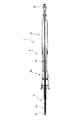
図1は内視鏡のチャンネルに挿入されて使用される内視鏡用処置具の全体を示している。内視鏡用処置具1は、内視鏡のチャンネルに挿入されて実際の処置を行う鉗子本体2と、鉗子本体2のチャンネルに対する位置調整や鉗子カップの開閉操作を行う操作部本体3とからなっている。
鉗子本体2は、内視鏡のチャンネルに挿入される外シース10と、外シース10内に、外シース10の軸線方向に沿って移動可能に配置されるコイルシース(鉗子シース)11と、コイルシース11の先端に互いに開閉可能に取り付けられた一対の鉗子カップ13と、コイルシース11内に、コイルシースの軸線方向に沿って移動可能に配置されるとともに鉗子カップ13に接続されて、それ自身が軸線方向に移動したときに鉗子カップ13を開閉する操作ワイヤ14とを備える。
なお、この明細書では、内視鏡のチャンネルに挿入されることを前提とし、内視鏡用処置具の各構成部材において、図1における左側を先端側、右側を基端側と呼ぶ。
FIG. 1 shows an entire endoscope treatment tool used by being inserted into an endoscope channel. The endoscope treatment tool 1 includes a
The
In this specification, on the premise that the component is inserted into the channel of the endoscope, the left side in FIG. 1 is referred to as the distal end side and the right side is referred to as the proximal end side in each component of the endoscope treatment tool.
外シース10は、内視鏡の挿入部の湾曲に追従して変形可能なように、可撓性を有するパイプ材、例えば4フッ化エチレン樹脂等のチューブによって構成される。
コイルシース11は、可撓性を有し、かつ、基端部側からの押し込み力が、先端部まで伝達されるように、例えば、ステンレス鋼線を密着状態で巻かれたものが利用される。
The
As the
一対の鉗子カップ13は、図5に示すように、中央から先端部にかけて断面半円状のカップ形状とされている。一対の鉗子カップ13のうちの一方の鉗子カップ13、ここでは図5における上側の鉗子カップの先端には、円錐状に尖った針状部12が形成されている。針状部12は、鉗子カップ本体から先端側へ張り出すように、かつ、鉗子カップの開閉動作に支障が無い範囲で、一方の鉗子カップから他方の鉗子カップ側へ張り出すように形成されている。そして、針状部12の先端中心12aは、一対の鉗子カップ13の中心に位置する突き合わせ部分に配置される。
鉗子カップ13の中間部は、コイルシース11の先端部に取り付けられたベース板15に、ピン16を介して回転可能に取り付けられている。また、鉗子カップ13の基端部は、ピン17を介して対をなすリンク部材18、18の先端にそれぞれ連結され、リンク部材18、18の基端部は、ピン19を介して連結棒20に連結されている。なお、連結棒20は操作ワイヤ14の先端部に連結されている。
As shown in FIG. 5, the pair of
An intermediate portion of the
そして、鉗子カップ13、リンク部材18及び連結棒20は、リンク機構21を構成し、このリンク機構21によって、操作ワイヤ14がコイルシース11に対して先端側へ移動する際、図16、図17に示すように、一対の鉗子カップ13を開操作し、操作ワイヤ14がコイルシース11に対して基端側へ移動する際、図18に示すように、一対の鉗子カップ13を閉操作する。
The
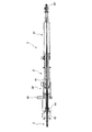
操作部本体3は、内視鏡のチャンネルの挿入口に固定され、かつ、外シース10の基端部に接続された内視鏡連結具30と、内視鏡連結具30に外シース10の基端部の軸線方向に沿って移動可能に取り付けられ、かつ、コイルシース11の基端部に接続されたスライダ(第1の操作部)31と、このスライダ31にコイルシース11の基端部の軸線方向に沿って移動可能に取り付けられ、かつ、操作ワイヤ14の基端部に接続されたボタン(第2の操作部)32とを、主に構成要素としている。
The operation unit
内視鏡連結具30について説明すると、符号41は、内視鏡のチャンネルの挿入口43に同軸状に組み付けられる円筒状の連結部材を示し(図8参照)、この連結部材41の先端部には、図4に示すように、ロック部材42が連結部材の軸線に直交する方向へスライド自在に連設されている。連結部材41は、図8に示すように、内部に内視鏡のチャンネル挿入口43に嵌合されるアダプタ鉗子栓44が嵌合された状態で、ロック部材42が図10における下方にスライドされることにより、アダプタ鉗子栓44を介して、内視鏡のチャンネル挿入口43に液密状態で固定される。
The
連結部材41には軸線に沿って操作部支持パイプ部材45が取り付けられており、この操作部支持パイプ材45は外シース10に外嵌される。
連結部材41の基端側には、パイプ固定部材46の先端部が連結部材41の軸線に沿って移動可能に挿入されている。パイプ固定部材46は、連結部材41との間に介在される螺子47を締め付けることによって、連結部材41に対する固定位置が任意に設定できる。
An operation portion
A distal end portion of the
パイプ固定部材46の先端には、シース固定部材48を介して、外シース10の基端部が接続されている。パイプ固定部材46の基端側にはスライダ受け49が、パイプ固定部材46と同軸状に連結されている。スライダ受け49およびパイプ固定部材46の軸線に沿って形成された貫通孔49a、46aには、それぞれコイルシース11が挿通される。
ここで、連結部材41、パイプ固定部材46及びスライダ受け49等は、前記内視鏡連結具30を構成している。また、パイプ固定部材46、螺子47およびシース固定部材48は、連結部材41に対する外シース10の基端部の固定位置を調整するシース固定位置調整機構50を構成している。
A proximal end portion of the
Here, the connecting
スライダ受け49の基端側外周にはスライダ31が、スライダ受け49の外周に形成されたスライド溝49bに外嵌されることで、スライダ受け49に対して同軸状にかつ軸線方向に移動可能に取り付けられる。スライダ31は、スライダ受け49に外嵌するスライダ本体52と、スライダ本体52の先端側に取り付けられた抜け止め部材54と、スライダ本体52の基端側に取り付けられたコイルシース連結部材55から構成される。
スライダ本体52には軸線に沿って貫通孔52aが形成され、この貫通孔52aにはコイルシース11が挿通される。スライダ本体52は、ここでは、図15に示すように、操作者が片手で握れるパイプ状のハンドルにより構成されている。
The
A through
スライダ本体52のスライダ受け49に対する先端側への移動限界位置は、スライダ受け49の外周にその軸線方向に移動可能かつ螺子56aによって任意の位置に固定されるストッパ(第1の操作部ストッパ)56により決定される。また、スライダ本体52のスライダ受け49に対する基端側の移動限界位置は、抜け止め部材54が、スライダ受け49の基端部に形成された外フランジ49bに当接することで決定される。
ここで、スライダ本体52を先端側へ移動させると、コイルシース連結部材55、コイルシース11及び鉗子カップ13が一体的に同方向へ移動する。また、逆に、スライダ本体52を基端側へ移動させると、コイルシース連結部材55、コイルシース11及び鉗子カップ13が一体的に同方向へ移動する。
なお、スライダ受け49の略中央部外周にはリング状の溝が形成されており、図3に示すように、このリング溝に取り付けられるCリング57によって、ストッパ56の先端側へのそれ以上の移動が規制される。
The movement limit position of the slider
Here, when the slider
A ring-shaped groove is formed on the outer periphery of the substantially central portion of the
コイルシース連結部材55は、図6に示すように全体が円筒状に形成されていて、先端側の小径部58と基端側の大径部59とを有する。小径部58は、スライダ本体52の基端部に形成された貫通孔に挿入されて固定されている。また、小径部58には前記コイルシース11の基端部が挿入された状態で、接着材等の適宜固定手段で固定されている。
コイルシース連結部材の大径部59の内部には、先端側から基端側にかけて、スプリング受け(弾性部材ストッパ)60、コイルスプリング(弾性部材)61及びボタン32の一部が収納される。また、コイルシース連結部材の大径部59には操作ワイヤ14が挿通されていて、操作ワイヤ14の基端部は前述したように前記ボタン32に固定されている。
As shown in FIG. 6, the entire coil
Inside the
コイルシース連結部材55の大径部59の側壁には、クランク溝59aが互いに対称をなすよう180ずれて形成されており、このクランク溝59aにはスプリング受け60のネック部60aが嵌合される。そして、スプリング受け60のネック部60aが、クランク溝59aの縦溝59aaに係合されるか横溝59abに係合されるかで、スプリング受け60は、コイルスプリング61に必ず当接する位置にあるか、あるいはコイルスプリング61に必ずしも当接しないフリーの位置にあるかのいずれかが択一的に選択できるようになっている。つまり、大径部59のクランク溝59aは、スプリング受け60のネック部60aと相俟って、スプリング受け60の位置を定める位置決め機構を構成している。
そして、スプリング受け60がクランク溝59aの横溝59abに係合してコイルスプリング61に必ずと当接する位置にあるとき、つまり、図7に示す状態にあるときには、コイルスプリング61によって常時ボタン32を基端側へ押圧することとなる。この状態で、操作者がボタン32を先端側へ押圧操作すると、操作ワイヤ14が先端側に押されて鉗子カップ13を開らき、ボタン32の押圧を解除すると、コイルスプリング61の付勢力によって操作ワイヤ14が基端側へ押し戻されて元の位置に戻り、鉗子カップ13を閉じる。
なお、コイルシース連結部材の大径部59の基端部にはキャップ62が嵌合されていて、このキャップ62がボタン32の先端側に設けられた大径部32aに係合することで、ボタン32の抜け止めを果たす。
A
When the
Note that a
次に、前記内視鏡用処置具を用いた、被検者の実質臓器の組織採取方法について説明する。
予め滅菌処理された内視鏡用処置具を滅菌パックから取り出し、図7に示すように、スプリング受け60のネック部60aの大径部のクランク溝59aに対する係合位置を、縦溝59aaから横溝59abへずらして、スプリング受け60をコイルスプリング61に必ず当接する位置にセットする。これにより、コイルスプリング61がボタン32を、常時基端側(図7中右側)へ付勢することとなる。
なお、滅菌処理されるとき、スプリング受け60は、そのネック部60aが縦溝59aaに係合される位置にあって、必ずしもコイルスプリング61に当接しないフリーの状態になる。したがって、部品同士が当接状態になるのを回避することができ、滅菌処理がスムーズに行われる。
Next, a method for collecting a tissue of a subject's parenchymal organ using the endoscope treatment tool will be described.
The endoscopic treatment tool that has been sterilized in advance is taken out of the sterilization pack, and as shown in FIG. 7, the engagement position of the
When sterilization is performed, the
前述したようにスプリング受け60をコイルスプリング61に必ず当接する位置にセットした内視鏡用処置具1を、内視鏡のチャンネルに挿入口43から挿入する。
具体的には、内部にコイルシース11及び鉗子カップ13等を挿入セットされた外シース10をチャンネル内に挿入し、図8に示すように、チャンネル挿入口43にアダプタ鉗子栓44を嵌合させ、さらに、連結部材41をチャンネル挿入口43側へ移動させてアダプタ鉗子栓44に嵌合させる(図9参照)。この状態で、図10に示すように、ロック部材42を連結部材41の軸線と直行する方向へ移動させてロックする。これにより、内視鏡用処置具1が内視鏡から不用意に外れなくなるように固定される。
As described above, the endoscope treatment tool 1 in which the
Specifically, the
次に、内視鏡用処置具1をセットされた内視鏡の挿入部を、被検者の口あるいは肛門等の自然開口から体腔内に挿入し、その先端を実質臓器Aの診断部位Aa近傍まで至らせる。
次に、図11に示すように、シース固定位置調整機構50の螺子47を緩め、パイプ固定部材46を連結部材41の先端側へ移動させて、内視鏡挿入部の先端に開口しているチャンネルの出口から外シース10の先端が若干量突出するように位置調整し、この状態で螺子47を締め付ける。このときの外シース10の先端の位置は、内視鏡挿入部の先端に取り付けた光学観察系及び超音波観察系で、それぞれ好適に観察できる位置である。
次に、図12に示すように、螺子56aを緩めストッパ56を、スライダ受け49の軸線方向に沿って先端側へ移動させて、Cリング57よりも若干手前の箇所に至らせる。このストッパ56の位置は、スライダ本体52を先端側への移動させる際の目安となる。このため、後述するように、操作者は安心してスライダ本体52の移動操作することができる。
Next, the insertion portion of the endoscope in which the endoscope treatment tool 1 is set is inserted into a body cavity from a natural opening such as the mouth or anus of the subject, and the tip thereof is a diagnostic site Aa of the substantial organ A. Bring to the vicinity.
Next, as shown in FIG. 11, the
Next, as shown in FIG. 12, the
次に、図13に示すように、操作者がスライダ本体52を手で握って、その先端がストッパ56に当接する位置まで移動させる。
これにより、コイルシース11およびコイルシース11の先端に取り付けた鉗子カップ13が先端側へ移動し、鉗子カップ13が外シース10から突出する。そして、鉗子カップ13の先端が実質臓器Aの診断部位Aaに穿刺する(図14参照)。このとき、鉗子カップ13は、先端に細く尖った針状部12が形成されているため、穿刺専用の処置具や切開用の処置具を用いることなく、鉗子カップ13そのままで、実質臓器Aの診断部位Aaに穿刺することができる。
Next, as shown in FIG. 13, the operator holds the
Thereby, the
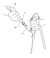
次に、図15、図16に示すように、スライダ本体52の基端側に取り付けてあるボタン32を、コイルスプリング61の付勢力に抗して親指で押しながら、ストッパ56がCリング57に当接する位置まで、スライダ本体52をさらに先端側へ移動させる。
ボタン32が押されることで、コイルシース11に対して操作ワイヤ14が先端側へ相対移動し、これにより、鉗子カップ13が開かれる。スライダ本体52がさらに先端側へ移動されることで、コイルシース11を介して鉗子カップ13が先端側へ移動される。つまり、鉗子カップ13は開かれると同時に先端側へ移動され、実質臓器Aの内部の診断部位Aaと対向する(図17参照)。
Next, as shown in FIGS. 15 and 16, the
When the
このような操作は、単に、片手でスライド本体52を握り、そのまま親指でボタン32を押しながら、握ったスライド本体を先端側に押し込むだけであり、1人の操作者であってもきわめて容易に行うことができる。
Such an operation is simply performed by simply holding the
次に、図18に示すように、ボタン32の押圧を解除する。これにより、コイルスプリング61の付勢力によって操作ワイヤ14が基端側へ移動され、鉗子カップ13は閉じる。つまり、鉗子カップ13によって、診断部位Aaの生検組織を採取する。この操作も、親指によるボタンの押圧操作を解除するだけ足りることから、きわめて容易な操作である。
Next, as shown in FIG. 18, the pressing of the
次に、図19に示すように、スライダ本体52とストッパ56を、基端側へ移動させてそれぞれ元の位置に戻す。
次に、図20に示すように、ロック部材42を連結部材41の軸線に直交する方向へ移動させて、元の位置に戻す。
最後に、図21に示すように、連結部材41とアダプタ鉗子栓44との嵌合を解いた後、内視鏡用処置具1を内視鏡のチャンネルから引き抜く。
以上の操作によって、被検者の実質臓器Aの内部から診断部位Aaの生検組織を採取することができる。
実施形態の変形例について説明する。
Next, as shown in FIG. 19, the slider
Next, as shown in FIG. 20, the
Finally, as shown in FIG. 21, after the fitting between the connecting
By the above operation, the biopsy tissue of the diagnostic site Aa can be collected from the inside of the subject's real organ A.
A modification of the embodiment will be described.
<第1の変形例>
図22〜図24は、鉗子カップの第1の変形例を示す。
前述した鉗子カップ13は、操作ワイヤ14が先端側へ移動して開操作されるときに、双方の鉗子カップ13がそれぞれピン16を中心に回転動作するが、この変形例では、対を成す鉗子カップ71(71a、71b)の内、一方の鉗子カップ71aのみが回転動作し、他方の鉗子カップ71bは回転動作しない。
<First Modification>
22 to 24 show a first modification of the forceps cup.
In the above-described
すなわち、コイルシース11の先端には他方の鉗子カップ71bが、コイルシース11と連結される連結部分と一体的に固定的に取り付けられている。他方の鉗子カップ71bの中間部にはピン73を介して、一方の鉗子カップ71aの中間部が回転可能に取り付けられている。一方の鉗子カップ71aの基端部はピン74を介してリンク部材75の先端部に連結され、リンク部材75の基端部はピン76を介して連結棒77に連結されている。なお、連結棒77は、操作ワイヤ14の先端に連結されている。
That is, the
つまり、一方の鉗子カップ71a、リンク部材75及び連結棒77は、リンク機構78を構成し、このリンク機構78によって、操作ワイヤ14がコイルシース11に対して先端側へ移動する際、図24に示すように、一方の鉗子カップ71aのみが回転して開動作し、操作ワイヤ14がコイルシース11に対して基端側へ移動する際、図23に示すように、一方の鉗子カップ71aのみが回転して閉動作する。
また、他方の鉗子カップ71bの先端部にのみ円錐状に尖った針状部72が形成され、一方の鉗子カップ71aの先端部には針状部が形成されていない。
That is, the one
Further, a conical pointed needle-
次に、この鉗子カップ71を用いた実質臓器Aの内部から診断部位Aaの生検組織を採取する方法について、前述した方法と異なる点のみ説明する。
まず、図23に示すように、コイルシース11を先端側へ移動させて、鉗子カップ71の先端に形成された針状部72を利用して、鉗子カップ71を実質臓器Aの診断部位Aaの近傍に穿刺する。このとき、コイルシース11に直接固定されている、非可動側鉗子カップである他方の鉗子カップ71bに針状部72を形成しているので、コイルシース11を押圧移動するときに、その押圧力が直接針状部72に伝わることとなり、鉗子カップ71によるスムーズな穿刺が可能となる。
Next, only a difference from the above-described method will be described with respect to a method of collecting the biopsy tissue of the diagnostic site Aa from the inside of the substantial organ A using the
First, as shown in FIG. 23, the
次に、さらに、コイルシース11をさらに先端側へ移動させながら、同時に、図示せぬボタンを押圧操作して操作ワイヤ14を前方へ移動させる。これにより、図24に示すように、一方の鉗子カップ71aが開きながら同時鉗子カップ71全体が先端側へ移動し、実質臓器Aの内部の診断部位Aaと対向する。
ここで、鉗子カップ71は、双方が開動作するのはなく、先端に針状部72を有しない一方の鉗子カップ71aのみが開動作する。このため、開動作の際、実質臓器によって抵抗力を受けることが少なく、スムーズな開動作が行える。
ちなみに、先端にそれぞれ針状部が形成された鉗子カップを開動作させるときには、針状部がそれぞれ実質臓器に突き刺さりながら回転することとなり、実質臓器から大きな抵抗力を受ける。
Next, while further moving the
Here, the
Incidentally, when opening the forceps cups each having a needle-like portion formed at the tip, the needle-like portions rotate while being pierced into the real organs, respectively, and receive a large resistance force from the real organs.
<第2の変形例>
図25及び図26は鉗子カップの第2の変形例を示す。
この変形例では、鉗子カップ81(81a、81b)の先端部に形成される針状部82が、先端を3角錐状(トラカールポイント)に形成されている。また、針状部82は、双方の鉗子カップ81a、81bに形成されるのではなく、片方の鉗子カップ81bにのみ形成されている。なお、この変形例では双方の鉗子カップ81a、81bが回転動作する。
<Second Modification>
25 and 26 show a second modification of the forceps cup.
In this modification, a needle-
<第3の変形例>
図27〜図29は、鉗子カップの第3の変形例を示す。
この変形例が、前述の図25、図26に示した鉗子カップと異なるところは、鉗子カップ91およびベース板92の表面に、それぞれディンプル部93を複数設けた点である。
このように鉗子カップ91およびベース板92の表面にディンプル部93を設けることにより、ディンプル部93からの反射波を受けることで、鉗子カップやベース板の位置を正確に把握することができ、超音波画像下での実質臓器内部の診断部位採取作業が容易になる。
<Third Modification>
27 to 29 show a third modification of the forceps cup.
This modification is different from the forceps cup shown in FIGS. 25 and 26 described above in that a plurality of
By providing the
<第4の変形例>
図30、図31は鉗子カップの変形例を示す。
この変形例では、鉗子カップ101(101a、101b)の先端部に形成される針状部102が、先端を図30における下方から上方に向けて斜めにカットし、このカットされた部分の両サイドをさらに斜めにカットされた形状(ランセットポイント)になっている。また、この変形例でも、針状部102は、双方の鉗子カップ101a、101bに形成されるのではなく、片方の鉗子カップ101bにのみ形成されている。なお、この変形例でも双方の鉗子カップ101a、101bが回転動作する。
<Fourth Modification>
30 and 31 show a modification of the forceps cup.
In this modified example, the needle-
なお、本発明の技術範囲は上記実施形態に限定されるものではなく、本発明の趣旨を逸脱しない範囲において種々の変更を加えることが可能である。
例えば、上記実施形態では、鉗子カップ13,71(71a、71b)、81(81a、81b)、91、101(101a、101b)が2つある例について説明しているが、これに限られることなく、鉗子カップが3以上あってもよい。
また、上記実施形態では、鉗子カップを開閉操作するボタン32をコイルスプリング61によって自動復帰する構成にしているが、これに限られることなく、他の弾性部材、例えば、ゴムによって自動復帰させてもよい。さらに、弾性部材を用いることなく、操作者が手動によって復帰させる構成にしても良い。
The technical scope of the present invention is not limited to the above embodiment, and various modifications can be made without departing from the spirit of the present invention.
For example, in the embodiment described above, an example in which there are two
In the above embodiment, the
また、上記実施形態では、鉗子カップの一方にのみ針状部を形成したが、これに限られることなく、複数ある鉗子カップそれぞれに針状部を設けても良い。
また、上記実施形態では、内視鏡のチャンネルの挿入口43に内視鏡用処置具を固定するための、連結部材41およびロック部材42を備えているが、これら部材41、42は必ずしも必要でものはなく、なくても本発明は成立する。また、連結部材41に対してパイプ固定部材46の位置を調整するための螺子47も同様に、なくても本発明は成立する。
Moreover, in the said embodiment, although the needle-shaped part was formed only in one of the forceps cups, you may provide a needle-shaped part in each of several forceps cups, without being restricted to this.
Moreover, in the said embodiment, although the
1…内視鏡用処置具、2…鉗子本体、3…操作部本体、10…外シース、11…コイルシース(鉗子シース)、12…針状部、13…鉗子カップ、14…操作ワイヤ、30…内視鏡連結具、31…スライダ(第1の操作部)、32…ボタン(第2の操作部)、50…シース固定位置調整機構、56…ストッパ(第1の操作部ストッパ)、59a…クランク溝(位置決め機構)、60…スプリング受け(弾性部材ストッパ)、60a…ネック部(位置決め機構)、61…コイルスプリング(弾性部材)
DESCRIPTION OF SYMBOLS 1 ... Endoscopic treatment tool, 2 ... Forceps main body, 3 ... Operation part main body, 10 ... Outer sheath, 11 ... Coil sheath (forceps sheath), 12 ... Needle-shaped part, 13 ... Forceps cup, 14 ... Operation wire, 30 ... endoscope connector, 31 ... slider (first operation part), 32 ... button (second operation part), 50 ... sheath fixing position adjusting mechanism, 56 ... stopper (first operation part stopper), 59a ... Crank groove (positioning mechanism), 60 ... Spring receiver (elastic member stopper), 60a ... Neck portion (positioning mechanism), 61 ... Coil spring (elastic member)
Claims (9)
前記外シース内にその軸線方向に沿って移動可能に配置される鉗子シースと、
前記鉗子シースの先端に取り付けられ、かつ、少なくとも一つに先端に尖った針状部が形成されて、互いに協働して全体で開閉可能な複数の鉗子カップと、
前記鉗子シース内にその軸線方向に沿って移動可能に配置されるとともに前記鉗子カップに接続され、それ自身の軸線方向に移動されたときに前記鉗子カップを開閉操作する操作ワイヤと、
前記外シースの基端部の軸線方向に沿って移動可能に取り付けられ、かつ、前記鉗子シースの基端部に接続された第1の操作部と、
前記第1の操作部に、前記鉗子シースの基端部の軸線方向に沿って移動可能に取り付けられ、かつ、前記操作ワイヤの基端部に接続された第2の操作部と、
を含み、
前記第2の操作部は、押圧操作されるボタンであり、
前記ボタンには、前記押圧操作が解かれたときに、前記ボタンを元の位置に戻す弾性部材が付設され、
前記弾性部材の前記ボタンが存する側とは逆側に弾性部材ストッパが配置され、前記弾性部材ストッパは、位置決め機構によって前記弾性部材に当接する当接位置と前記弾性部材に当接しないフリー位置のいずれかの位置に、択一的に位置きめされる内視鏡用処置具。 An outer sheath that is inserted into the channel of the endoscope;
A forceps sheath disposed movably along the axial direction in the outer sheath;
A plurality of forceps cups attached to the distal end of the forceps sheath and having at least one pointed needle-like portion formed therein and capable of opening and closing in cooperation with each other;
An operation wire that is movably disposed along the axial direction in the forceps sheath and connected to the forceps cup, and opens and closes the forceps cup when moved in its own axial direction;
A first operation portion attached to be movable along the axial direction of the proximal end portion of the outer sheath and connected to the proximal end portion of the forceps sheath;
A second operating portion attached to the first operating portion movably along the axial direction of the proximal end portion of the forceps sheath, and connected to the proximal end portion of the operating wire;
Only including,
The second operation unit is a button to be pressed,
The button is provided with an elastic member that returns the button to its original position when the pressing operation is released,
An elastic member stopper is disposed on the opposite side of the elastic member to the side where the button exists, and the elastic member stopper has a contact position that contacts the elastic member by a positioning mechanism and a free position that does not contact the elastic member. An endoscopic treatment tool that is alternatively positioned at any position .
Applications Claiming Priority (1)
| Application Number | Priority Date | Filing Date | Title |
|---|---|---|---|
| US11/411,276 US8197396B2 (en) | 2006-04-26 | 2006-04-26 | Treatment tool for endoscope and medical procedure |
Related Child Applications (1)
| Application Number | Title | Priority Date | Filing Date |
|---|---|---|---|
| JP2010198111A Division JP5282076B2 (en) | 2006-04-26 | 2010-09-03 | Endoscopic treatment tool |
Publications (2)
| Publication Number | Publication Date |
|---|---|
| JP2007289673A JP2007289673A (en) | 2007-11-08 |
| JP4616301B2 true JP4616301B2 (en) | 2011-01-19 |
Family
ID=38309992
Family Applications (2)
| Application Number | Title | Priority Date | Filing Date |
|---|---|---|---|
| JP2007081351A Expired - Fee Related JP4616301B2 (en) | 2006-04-26 | 2007-03-27 | Endoscopic treatment tool |
| JP2010198111A Expired - Fee Related JP5282076B2 (en) | 2006-04-26 | 2010-09-03 | Endoscopic treatment tool |
Family Applications After (1)
| Application Number | Title | Priority Date | Filing Date |
|---|---|---|---|
| JP2010198111A Expired - Fee Related JP5282076B2 (en) | 2006-04-26 | 2010-09-03 | Endoscopic treatment tool |
Country Status (4)
| Country | Link |
|---|---|
| US (2) | US8197396B2 (en) |
| EP (1) | EP1849415B1 (en) |
| JP (2) | JP4616301B2 (en) |
| DE (1) | DE602007011342D1 (en) |
Families Citing this family (34)
| Publication number | Priority date | Publication date | Assignee | Title |
|---|---|---|---|---|
| JP4880251B2 (en) * | 2005-06-21 | 2012-02-22 | オリンパスメディカルシステムズ株式会社 | High frequency treatment tool |
| JP4526544B2 (en) * | 2007-02-08 | 2010-08-18 | オリンパスメディカルシステムズ株式会社 | Endoscopic treatment tool |
| EP1955657B1 (en) * | 2007-02-08 | 2011-01-12 | Olympus Medical Systems Corp. | Treatment tool for endoscope |
| JP5393491B2 (en) | 2009-03-04 | 2014-01-22 | Hoya株式会社 | Ultrasound endoscope puncture needle device |
| WO2011095156A1 (en) * | 2010-02-02 | 2011-08-11 | Medi-Globe Gmbh | Device for establishing the penetration depth of a tubular or rod-shaped sliding part in a receiving part and medical handpiece using such devices |
| DE102010010798A1 (en) * | 2010-03-09 | 2011-09-15 | Epflex Feinwerktechnik Gmbh | Hand-operated functional hose instrument and operating device therefor |
| WO2011111271A1 (en) | 2010-03-11 | 2011-09-15 | オリンパスメディカルシステムズ株式会社 | Forceps suitable for intraperitoneal manipulations and technique of using forceps suitable for intraperitoneal manipulations |
| DE102010013309A1 (en) * | 2010-03-29 | 2011-09-29 | Karl Storz Gmbh & Co. Kg | Lifting device for moving a probe in a medical instrument |
| WO2012032302A1 (en) | 2010-09-09 | 2012-03-15 | Queen Mary & Westfiled College | Method and apparatus for forming stoma trephines and anastomoses |
| JP2013537057A (en) * | 2010-09-09 | 2013-09-30 | クイーン マリー アンド ウエストフィールド カレッジ、ユニバーシティ オブ ロンドン | Forceps with trocar tip |
| JP2012115471A (en) * | 2010-11-30 | 2012-06-21 | Olympus Corp | Medical treatment instrument, and manipulator |
| JP5155499B2 (en) * | 2011-02-16 | 2013-03-06 | オリンパスメディカルシステムズ株式会社 | Medical equipment system |
| US20130023790A1 (en) * | 2011-07-19 | 2013-01-24 | Schaeffer Jeremy R | Biopsy device |
| BR112014008970A2 (en) | 2011-10-15 | 2017-05-02 | Transmed7 Llc | methods and devices for soft tissue control biopsy |
| US8708889B2 (en) * | 2011-10-24 | 2014-04-29 | Trocare, LLC | Jawed trocar assembly |
| CN103429174B (en) * | 2012-03-13 | 2015-12-23 | 奥林巴斯株式会社 | Endoscope treatment tool |
| CN104254284B (en) | 2012-08-13 | 2016-06-29 | 奥林巴斯株式会社 | Endoscope treatment tool |
| CN104519783B (en) * | 2013-02-27 | 2016-11-23 | 奥林巴斯株式会社 | The advance and retreat assistive device of endoscopic surgical apparatus |
| US9463001B2 (en) | 2013-05-28 | 2016-10-11 | Transmed7, Llc | Soft tissue coring biopsy devices and methods |
| US9155527B2 (en) | 2013-08-22 | 2015-10-13 | Transmed7, Llc | Soft tissue coring biopsy devices and methods |
| EP3043719B1 (en) | 2013-09-12 | 2022-04-13 | Transmed7, LLC | Tissue coring biopsy devices |
| CN105188508B (en) * | 2013-11-21 | 2017-04-12 | 奥林巴斯株式会社 | Endoscopic treatment device |
| JP1532468S (en) * | 2014-09-27 | 2015-08-31 | ||
| JP1532467S (en) * | 2014-09-27 | 2015-08-31 | ||
| US10231750B2 (en) | 2014-09-29 | 2019-03-19 | Transmed7, Llc | Excisional device distal working end actuation mechanism and method |
| DE202015105488U1 (en) * | 2015-10-16 | 2017-01-17 | M T W - Endoskopie W. Haag Kg | biopsy forceps |
| WO2017087958A1 (en) * | 2015-11-20 | 2017-05-26 | Boston Scientific Scimed, Inc. | Actuation handle for accessory devices |
| CN109069137B (en) * | 2016-04-04 | 2021-08-20 | 奥林巴斯株式会社 | Treatment tool for endoscope |
| JP2019201673A (en) * | 2016-08-18 | 2019-11-28 | オリンパス株式会社 | Movement/retreat aid for treatment instrument and endoscope system |
| WO2018098271A1 (en) * | 2016-11-23 | 2018-05-31 | Boston Scientific Scimed, Inc. | Biopsy devices |
| CN113710305A (en) * | 2019-05-24 | 2021-11-26 | 贝克顿·迪金森公司 | Needle track assist device including components and method thereof |
| USD950055S1 (en) * | 2019-10-17 | 2022-04-26 | Robert A. Van Wyk | Surgical jaws |
| CN113081271B (en) * | 2021-03-17 | 2022-07-15 | 北京铸正机器人有限公司 | Minimally invasive surgery robot |
| USD1017031S1 (en) * | 2021-09-10 | 2024-03-05 | Aegis Spine, Inc. | Medical device adapter |
Citations (6)
| Publication number | Priority date | Publication date | Assignee | Title |
|---|---|---|---|---|
| JPS62253041A (en) * | 1986-04-25 | 1987-11-04 | オリンパス光学工業株式会社 | Treatment jig for endoscope |
| JPH05237120A (en) * | 1992-02-27 | 1993-09-17 | Asahi Optical Co Ltd | Biopsy forceps for endoscope |
| JP2000201939A (en) * | 1999-01-12 | 2000-07-25 | Asahi Optical Co Ltd | Medical implement |
| JP2000342516A (en) * | 1999-06-03 | 2000-12-12 | Asahi Optical Co Ltd | Endoscope for treating and treating tool |
| JP2005198868A (en) * | 2004-01-16 | 2005-07-28 | Olympus Corp | Endo-therapy accessory for endoscope |
| JP2005312828A (en) * | 2004-04-30 | 2005-11-10 | Olympus Corp | Puncture needle |
Family Cites Families (16)
| Publication number | Priority date | Publication date | Assignee | Title |
|---|---|---|---|---|
| US3763860A (en) * | 1971-08-26 | 1973-10-09 | H Clarke | Laparoscopy instruments and method for suturing and ligation |
| US4763670A (en) | 1986-09-19 | 1988-08-16 | Microvasive, Inc. | Microbiological specimen sampling device |
| JPH03139340A (en) * | 1989-10-24 | 1991-06-13 | Olympus Optical Co Ltd | Treating implement for endoscope |
| US5383877A (en) * | 1991-05-01 | 1995-01-24 | Clarke; Henry C. | Instruments and method for suturing and ligation |
| US5312432A (en) * | 1992-05-01 | 1994-05-17 | Vance Products Inc. | Percutaneously insertable, needle-sized tissue retractor and system |
| US5776146A (en) * | 1993-10-20 | 1998-07-07 | Applied Medical Resources | Laparoscopic surgical clamp |
| DE19608768C2 (en) * | 1996-03-07 | 1999-12-23 | Dieter Lang | Medical forceps |
| US5819738A (en) * | 1996-07-03 | 1998-10-13 | Symbiosis Corporation | Jaw assembly having progressively larger teeth and endoscopic biopsy forceps instrument incorporating same |
| US6142956A (en) * | 1996-11-25 | 2000-11-07 | Symbiosis Corporation | Proximal actuation handle for a biopsy forceps instrument having irrigation and aspiration capabilities |
| US6517552B1 (en) * | 1997-10-29 | 2003-02-11 | Arthrex, Inc. | Suture retriever |
| DK200001852A (en) * | 1999-12-14 | 2001-06-15 | Asahi Optical Co Ltd | Manipulation section for an endoscopic treatment instrument |
| JP4716594B2 (en) * | 2000-04-17 | 2011-07-06 | オリンパス株式会社 | Endoscope |
| ES2432616T3 (en) * | 2003-09-15 | 2013-12-04 | Covidien Lp | Accessory system for use with bronchoscopes |
| US7789825B2 (en) | 2003-09-29 | 2010-09-07 | Ethicon Endo-Surgery, Inc. | Handle for endoscopic device |
| JP4370147B2 (en) | 2003-11-10 | 2009-11-25 | オリンパス株式会社 | Ultrasound puncture needle |
| US20060020274A1 (en) * | 2004-07-23 | 2006-01-26 | Usgi Medical Inc. | Manipulatable grasping needle |
-
2006
- 2006-04-26 US US11/411,276 patent/US8197396B2/en active Active
-
2007
- 2007-03-27 JP JP2007081351A patent/JP4616301B2/en not_active Expired - Fee Related
- 2007-04-16 DE DE602007011342T patent/DE602007011342D1/en active Active
- 2007-04-16 EP EP07007733A patent/EP1849415B1/en not_active Expired - Fee Related
-
2010
- 2010-09-03 JP JP2010198111A patent/JP5282076B2/en not_active Expired - Fee Related
-
2011
- 2011-11-30 US US13/307,557 patent/US8961558B2/en not_active Expired - Fee Related
Patent Citations (6)
| Publication number | Priority date | Publication date | Assignee | Title |
|---|---|---|---|---|
| JPS62253041A (en) * | 1986-04-25 | 1987-11-04 | オリンパス光学工業株式会社 | Treatment jig for endoscope |
| JPH05237120A (en) * | 1992-02-27 | 1993-09-17 | Asahi Optical Co Ltd | Biopsy forceps for endoscope |
| JP2000201939A (en) * | 1999-01-12 | 2000-07-25 | Asahi Optical Co Ltd | Medical implement |
| JP2000342516A (en) * | 1999-06-03 | 2000-12-12 | Asahi Optical Co Ltd | Endoscope for treating and treating tool |
| JP2005198868A (en) * | 2004-01-16 | 2005-07-28 | Olympus Corp | Endo-therapy accessory for endoscope |
| JP2005312828A (en) * | 2004-04-30 | 2005-11-10 | Olympus Corp | Puncture needle |
Also Published As
| Publication number | Publication date |
|---|---|
| US8197396B2 (en) | 2012-06-12 |
| JP2007289673A (en) | 2007-11-08 |
| US20120123201A1 (en) | 2012-05-17 |
| EP1849415B1 (en) | 2010-12-22 |
| US8961558B2 (en) | 2015-02-24 |
| JP2010274128A (en) | 2010-12-09 |
| DE602007011342D1 (en) | 2011-02-03 |
| US20070255311A1 (en) | 2007-11-01 |
| EP1849415A2 (en) | 2007-10-31 |
| JP5282076B2 (en) | 2013-09-04 |
| EP1849415A3 (en) | 2009-05-06 |
Similar Documents
| Publication | Publication Date | Title |
|---|---|---|
| JP4616301B2 (en) | Endoscopic treatment tool | |
| JP4320061B2 (en) | Endoscope control device | |
| JP4624485B2 (en) | Suture device and suture system | |
| US7306613B2 (en) | Endoscopic instruments | |
| JP5248596B2 (en) | Visualization obturator with handle | |
| US20130317291A1 (en) | Treatment system and endoscope system | |
| KR20100110801A (en) | Surgical instrument | |
| JP5797361B1 (en) | Endoscopic treatment tool | |
| JP2010536517A (en) | Trocar tube, trocar, obturator and / or rectoscope for performing transluminal endoscopic surgery through a natural body hole | |
| JP5591416B2 (en) | Endoscopic treatment tool | |
| JP5437233B2 (en) | Visualization entry trocar with moving blade | |
| US20130310684A1 (en) | Treatment instrument | |
| JP2015061669A (en) | Suturing device | |
| US20160354066A1 (en) | Needle tube | |
| JP5883117B2 (en) | Minimally invasive surgical system | |
| WO2016021290A1 (en) | Surgical instrument | |
| WO2015087939A1 (en) | Endoscope treatment instrument | |
| US11350814B2 (en) | Endoscope gripping device | |
| JP2006187471A (en) | Treatment instrument for endoscope | |
| JP4132343B2 (en) | Biopsy forceps | |
| JP2005319164A (en) | Treatment appliance for endoscope | |
| US11369367B2 (en) | Suturing device | |
| JPH08280700A (en) | Surgical appliance |
Legal Events
| Date | Code | Title | Description |
|---|---|---|---|
| A621 | Written request for application examination |
Free format text: JAPANESE INTERMEDIATE CODE: A621 Effective date: 20100113 |
|
| A977 | Report on retrieval |
Free format text: JAPANESE INTERMEDIATE CODE: A971007 Effective date: 20100527 |
|
| A131 | Notification of reasons for refusal |
Free format text: JAPANESE INTERMEDIATE CODE: A131 Effective date: 20100706 |
|
| A521 | Request for written amendment filed |
Free format text: JAPANESE INTERMEDIATE CODE: A523 Effective date: 20100903 |
|
| A521 | Request for written amendment filed |
Free format text: JAPANESE INTERMEDIATE CODE: A821 Effective date: 20100906 |
|
| TRDD | Decision of grant or rejection written | ||
| A01 | Written decision to grant a patent or to grant a registration (utility model) |
Free format text: JAPANESE INTERMEDIATE CODE: A01 Effective date: 20101005 |
|
| A01 | Written decision to grant a patent or to grant a registration (utility model) |
Free format text: JAPANESE INTERMEDIATE CODE: A01 |
|
| A61 | First payment of annual fees (during grant procedure) |
Free format text: JAPANESE INTERMEDIATE CODE: A61 Effective date: 20101021 |
|
| R151 | Written notification of patent or utility model registration |
Ref document number: 4616301 Country of ref document: JP Free format text: JAPANESE INTERMEDIATE CODE: R151 |
|
| FPAY | Renewal fee payment (event date is renewal date of database) |
Free format text: PAYMENT UNTIL: 20131029 Year of fee payment: 3 |
|
| S111 | Request for change of ownership or part of ownership |
Free format text: JAPANESE INTERMEDIATE CODE: R313111 |
|
| R350 | Written notification of registration of transfer |
Free format text: JAPANESE INTERMEDIATE CODE: R350 |
|
| S531 | Written request for registration of change of domicile |
Free format text: JAPANESE INTERMEDIATE CODE: R313531 |
|
| R350 | Written notification of registration of transfer |
Free format text: JAPANESE INTERMEDIATE CODE: R350 |
|
| R250 | Receipt of annual fees |
Free format text: JAPANESE INTERMEDIATE CODE: R250 |
|
| R250 | Receipt of annual fees |
Free format text: JAPANESE INTERMEDIATE CODE: R250 |
|
| R250 | Receipt of annual fees |
Free format text: JAPANESE INTERMEDIATE CODE: R250 |
|
| R250 | Receipt of annual fees |
Free format text: JAPANESE INTERMEDIATE CODE: R250 |
|
| LAPS | Cancellation because of no payment of annual fees |