JP4612837B2 - Lens fixing method and optical apparatus - Google Patents
Lens fixing method and optical apparatus Download PDFInfo
- Publication number
- JP4612837B2 JP4612837B2 JP2004376819A JP2004376819A JP4612837B2 JP 4612837 B2 JP4612837 B2 JP 4612837B2 JP 2004376819 A JP2004376819 A JP 2004376819A JP 2004376819 A JP2004376819 A JP 2004376819A JP 4612837 B2 JP4612837 B2 JP 4612837B2
- Authority
- JP
- Japan
- Prior art keywords
- lens
- intermediate member
- fixing
- fixed
- fixing method
- Prior art date
- Legal status (The legal status is an assumption and is not a legal conclusion. Google has not performed a legal analysis and makes no representation as to the accuracy of the status listed.)
- Expired - Fee Related
Links
Images


Description
本発明は、レンズ相互を固定するレンズ固定方法及び該方法により相互に固定された複数のレンズを有する光学機器に関するものである。 The present invention relates to a lens fixing method for fixing lenses to each other and an optical apparatus having a plurality of lenses fixed to each other by the method.
従来、この種のレンズ固定に関する技術として下記のものがある。 Conventionally, there are the following techniques related to this type of lens fixing.
(1)プラスチックの鏡筒内に、第一のレンズを挿入し、さらに第二のレンズを挿入した後、第二のレンズの外周部側面を第一のレンズ外周部側面に当接させ、その後、鏡筒の先端部の一片を熱カシメ等の方法により変形させ、固定する方法が知られている。 (1) After the first lens is inserted into the plastic lens barrel and the second lens is further inserted, the outer peripheral side surface of the second lens is brought into contact with the first lens outer peripheral side surface, and thereafter A method is known in which a piece of the tip of the lens barrel is deformed and fixed by a method such as thermal caulking.
(2)それとは別に、レンズ外周部とレンズ枠を紫外線硬化型接着剤等により固定する方法が知られている。 (2) Aside from that, a method of fixing the lens outer peripheral portion and the lens frame with an ultraviolet curable adhesive or the like is known.
(3)また、光学部材であるレンズ同士の組立体の固定方法として、鏡筒内に固定する前に、第一のレンズと第二のレンズの光軸を一致させた後に、接着剤で鏡筒内に固着するような方法が知られている(特許文献1)。 (3) Also, as a method of fixing the assembly of lenses that are optical members, the optical axes of the first lens and the second lens are aligned with each other before being fixed in the lens barrel, and then mirrored with an adhesive. A method of fixing in a cylinder is known (Patent Document 1).
(4)また、レンズをレンズ枠などに固定する方法として、レンズをレーザ光透過プラスチックにより形成し、レーザ光吸収プラスチックにより形成されたレンズ枠の溶着面にレンズを当接させて、レンズを通してレーザ光をレンズ枠の溶着面に照射し、固定する方法が知られている(特許文献2)。
しかしながら、上述の従来例では、下記の問題がある。 However, the above-described conventional example has the following problems.
(1)鏡筒をカシメ治具により熱で溶かし、レンズ外周先端部を覆うように構成するため、カシメに要する時間が長くなり、組立工数が増大し、コストアップを招く問題が生じる。また、カシメ治具によりレンズ保持部材外周部を熱により溶かして固定する必要上、レンズ保持部材およびレンズに対して押圧する力がかかるので、組立後のレンズ位置精度が保証し難いという問題があった(近年の小型化されたレンズ群は、偏芯や光軸に対する傾きが原因となって生じる性能のばらつき、つまり性能の劣化に対して非常に敏感であり、したがって、レンズの小型化が進む状況下において、従来の組立方法では、高性能のズームレンズを量産することは難しい)。 (1) Since the lens barrel is melted by heat with a caulking jig so as to cover the tip of the outer periphery of the lens, the time required for caulking becomes longer, the number of assembling steps increases, and there is a problem of increasing costs. In addition, since it is necessary to melt and fix the outer periphery of the lens holding member with heat with a caulking jig, a pressing force is applied to the lens holding member and the lens, which makes it difficult to guarantee the accuracy of the lens position after assembly. (Recent lens groups that have been miniaturized in recent years are extremely sensitive to performance variations caused by decentering and tilting with respect to the optical axis, that is, performance degradation, and therefore, lens miniaturization advances. Under the circumstances, it is difficult to mass-produce high-performance zoom lenses with the conventional assembly method).
(2)レンズ保持部材とレンズ外周部を紫外線硬化型接着剤により固定する方法においては、紫外線硬化型接着剤を塗布した後、紫外線を照射するまでの間に液状の接着剤がレンズ保持部材の外周面に流れ出し、これが紫外線照射により硬化すると、組立後に周囲の部品との干渉を生じ、作動不良の原因、特に光学性能の悪化を招くという問題があった。また、液状接着剤が、レンズ保持部材とレンズ外周部との隙間からレンズ内部に流れ込み、光路を遮り、レンズ光学性能を保証できなくなる等の問題があった。また、紫外線硬化型接着剤が固化する際、不均一な収縮が発生し、接着開始前のレンズ位置からレンズがずれて固定され、光学性能が低下することがあった。また、従来例においては、迷光など有効光束以外の光を遮断するためにレンズ外周面に遮光剤を塗布する必要があった。 (2) In the method of fixing the lens holding member and the outer periphery of the lens with the ultraviolet curable adhesive, the liquid adhesive is applied to the lens holding member after the ultraviolet curable adhesive is applied and before the ultraviolet rays are irradiated. When it flows out to the outer peripheral surface and is cured by irradiation with ultraviolet rays, there is a problem that interference with surrounding parts occurs after assembling, resulting in a malfunction and particularly deterioration of optical performance. Further, there is a problem that the liquid adhesive flows into the lens through a gap between the lens holding member and the lens outer peripheral portion, interrupts the optical path, and cannot guarantee the lens optical performance. In addition, when the ultraviolet curable adhesive is solidified, non-uniform shrinkage occurs, and the lens is displaced and fixed from the lens position before the start of adhesion, and the optical performance may be deteriorated. In the conventional example, it is necessary to apply a light shielding agent to the outer peripheral surface of the lens in order to block light other than the effective light beam such as stray light.
(3)上述の従来方法によれば、鏡筒内に固定する前に、非接合レンズと接合レンズの光軸とを一致させて固着するので、光軸のずれを修正可能であり、またレンズのうち少なくとも一方の外周部側面に段差が設けられているため、段差内に接着剤が入り込み、研磨面にはみ出すことがない、という利点がある反面、接合レンズと非接合レンズを紫外線硬化型接着剤などの接着剤で接着した後に、さらに鏡筒内に接着するなどしているため、遮光剤や接着剤の固着に要する時間が長くなり、組立工数が増大し、コストアップを招く問題がある。さらに、紫外線硬化型接着剤を用いたガラス製のレンズの接着においては、固着の際に、紫外線硬化型接着剤とガラスの線膨張係数の違いから、レンズが剥離するおそれがあった。 (3) According to the conventional method described above, the optical axis of the non-bonded lens and the cemented lens are fixed and fixed before being fixed in the lens barrel. Since there is a step on the side surface of at least one of the two, there is an advantage that the adhesive enters the step and does not protrude onto the polished surface, but the bonded lens and the non-bonded lens are bonded with ultraviolet curing. After bonding with an adhesive such as an adhesive, the time required for fixing the light-shielding agent or the adhesive is increased, and the number of assembling steps increases, resulting in an increase in cost. . Further, in the adhesion of a glass lens using an ultraviolet curable adhesive, the lens may be peeled off due to the difference in the linear expansion coefficient between the ultraviolet curable adhesive and the glass.
(4)レンズ相互間を固定する場合に、レンズにレーザ光による溶着面を形成することが困難である。 (4) When fixing between lenses, it is difficult to form the welding surface by a laser beam on a lens.
(発明の目的)
本発明の目的は、レンズ相互を高精度に且つ省スペースで固定することができるレンズ固定方法及び光学機器を提供することである。
(Object of invention)
An object of the present invention is to provide a lens fixing method and an optical apparatus that can fix lenses with high accuracy and space-saving.
上記目的を達成するために、本発明のレンズ固定方法は、第一のレンズに第二のレンズを固定するレンズ固定方法であって、光が照射されることで発熱する材料と、発熱することで接着力を増す材料とを含有する中間部材を、前記第一のレンズに対して位置決めする第一の位置決めステップと、前記第一のレンズに位置決めされた前記中間部材の第一の部分に光を照射する第一の照射ステップと、前記第一のレンズと前記第二のレンズとの間に前記中間部材が位置するように、前記第二のレンズを前記第一のレンズに対して位置決めする第二の位置決めステップと、前記中間部材の前記第一の部分とは異なる第二の部分に光を照射する第二の照射ステップとを有することを特徴としている。 In order to achieve the above object, the lens fixing method of the present invention is a lens fixing method for fixing a second lens to a first lens, which generates heat when irradiated with light and a material that generates heat. light intermediate member containing a material to increase the adhesion, the first portion of the first positioning step and said intermediate member positioned in said first lens to be positioned relative to the first lens in And positioning the second lens with respect to the first lens so that the intermediate member is positioned between the first lens and the second lens. It has a 2nd positioning step and a 2nd irradiation step which irradiates light to the 2nd part different from the said 1st part of the said intermediate member, It is characterized by the above-mentioned.
本発明によれば、レンズ相互を高精度に且つ省スペースで固定することができ、レンズ枠を小型にすることが可能となる。 According to the present invention, the lenses can be fixed with high accuracy and in a small space, and the lens frame can be reduced in size.
本発明を実施するための最良の形態は、後述する実施例1〜5に記載の通りである。 The best mode for carrying out the present invention is as described in Examples 1 to 5 described later.
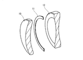
図1は、本発明の実施例1であるレンズ固定方法に用いられる構成部材を示す要部断面斜視図である。 FIG. 1 is a cross-sectional perspective view of a main part showing constituent members used in a lens fixing method that is Embodiment 1 of the present invention.
10と12は光学ガラスのレンズ、11は組み込み時にレンズ10とレンズ12との光入出射面間に介在する円形形状に形成されたシート材の中間部材である。この中間部材11は可視光線を遮光するような材料で構成されており、撮影光線以外の周辺部や図外の構成部品などからの反射有害光線を遮断する機能を有する光学絞り機能を兼ねている。中間部材11は熱を与えると接着力を増すような材料(例えば、ポリエステル、ポリイミド、ポリウレタン、アイオイマー樹脂、エチレンとメタクリル酸の共重合樹脂を主成分とするホットメルトシート、熱接着シート(熱硬化型)に近赤外光レーザを顕著に吸収する材料(例えば、カーボンブラック、染料や顔料等の所定の着色材)が混入されたもの)で形成されている。
10 and 12 are optical glass lenses, and 11 is an intermediate member of a sheet material formed in a circular shape interposed between the light incident and exit surfaces of the
図2はレンズ10、レンズ12、中間部材11が組み込まれた状態を示す要部断面図である。13はレーザ光であり、近赤外光を後述のように照射し、中間部材11の接着力を増加させることで、レンズ10とレンズ12を固定するためのものである。
FIG. 2 is a cross-sectional view of the main part showing a state in which the
実施例1のレンズ固定方法は以下のような順序に従ってレンズ10とレンズ12の固定を行うものである。
The lens fixing method of the first embodiment is to fix the
上述のように、レンズ10が中間部材11を介してレンズ12と組み込まれた状態において、図示しない押圧装置でレンズ10,12と中間部材11を密着させた状態に固定する。このとき、中間部材11が挟持されるレンズ10とレンズ12は、その外周端部において図示しない位置決め調整枠により光軸に垂直方向の位置が規制される。そのため、中間部材11はレンズ10とレンズ12の有効径内に介入することなく位置決めされる。この状態において、図示しないレーザ照射装置からスポット状のレーザ光13をレンズ12の光入出射面から入射させ、レンズ12を透過させ、中間部材11に対して照射させる。中間部材11は上述のように近赤外光を吸収するような材料で構成され、また、熱が与えられると接着力を増す部材で構成されているので、レーザ光13を吸収すると、瞬時に接着力が増加する。この際、中間部材11はレンズ10及び12と接着固定されることとなる。なお、所定の照射時間の後、レーザ照射を終了させ、レンズの固定工程が完了する。
As described above, when the
以上のように、中間部材11を熱することによりレンズ10,12を直接固定するようにしたので、高精度に且つ省スペースでレンズ10,12を固定することができる。そして、これらのレンズ10,12を支持するレンズ枠を小型にすることができる。
As described above, since the
なお、中間部材11とレンズ10とレンズ12の接触部は、図示しない押圧装置によるレンズ10とレンズ12の中間部材11との押圧を解き、図示しない位置決め調整枠を外しても、中間部材11の接着力によって常にレンズ10とレンズ12は固定されているため、ガタが生じることなく、高精度に位置決めされている。さらに、強い衝撃が加わった場合には、中間部材11が弾性変形することで衝撃を吸収し、レンズ10,12が割れることを防止する効果も有している。2枚のレンズ10,12が中間部材11と調整位置状態のまま固定されることとなる。
The contact portion of the
上述の実施例1において、レンズ10と12、中間部材11は、単に組み込まれた状態においてレーザ照射を受けるような構成での説明を行ったが、例えばレンズ10を真空吸引工具などにより保持した状態とし、中間部材11の位置決め調整と、レンズ12の偏芯および傾き調整を行い、その状態を保ったまま、調整後、レーザ照射を行うような構成にすることもできることはいうまでもない。
In Embodiment 1 described above, the
また、レーザ照射はスポット状に複数箇所で行うように構成したが、照射箇所はこれに限定されるものではなく、中間部材11の形状に合わせたレーザ光13を照射しても良い。
In addition, although the laser irradiation is configured to be performed at a plurality of spots in a spot shape, the irradiation spot is not limited to this, and the
また、スポット状のレーザ光を複数箇所に照射する場合には、中間部材11上の均等な位置間隔で照射することが好ましい。中間部材11の形状が樽型などリング形状ではない場合、照射位置は各辺の中間位置に照射するなど、均等な間隔でなくても良い。このとき各スポット位置は光軸を中心とする円の周上に配置されることが好ましい。
Moreover, when irradiating a spot-like laser beam to several places, it is preferable to irradiate with the equal position space | interval on the
また、レーザ光の照射は複数箇所に同時にスポット照射を行っても良いし、同時照射を行わない場合は、対角配置で順次スポット照射を行っても良い。 In addition, the laser beam irradiation may be performed at a plurality of spots at the same time. When simultaneous irradiation is not performed, spot irradiation may be performed sequentially in a diagonal arrangement.
また、例えば均等に3箇所(120度ずつの配置)同時照射を行った後、時計回りか、反時計回りに60度回転させレーザ照射を行い、計6箇所の固定を行うなど、レンズ10,12またはレーザ照射位置を回転させて固定を行っても良い。 Further, for example, after performing simultaneous irradiation at three locations (positions of 120 degrees each) equally and then rotating the laser clockwise by 60 degrees clockwise or counterclockwise to fix a total of six positions, etc. 12 or the laser irradiation position may be rotated for fixing.
また、合わせて、レーザ照射角度は中間部材11の表面に垂直に照射されるように設置しても良いし、垂直方向とは限らずに他方向から照射しても良い。
In addition, the laser irradiation angle may be set so that the surface of the
また、複数箇所を同時に照射するレーザ光は、厳密には同時ではなく、レンズ10,12の位置精度に影響が無い程度の時間差、例えば数十ms〜数百msの時間差で照射されるようにしても良い。
In addition, the laser beams for irradiating a plurality of locations at the same time are not exactly the same, but are irradiated with a time difference that does not affect the positional accuracy of the
また、上述のレンズに関しては、硝材から構成されたレンズであっても、また樹脂材料で構成されたレンズであっても、本発明の意図に反するものではないことはいうまでもない。 In addition, regarding the lens described above, it goes without saying that a lens made of a glass material or a lens made of a resin material is not contrary to the intention of the present invention.
また、上述のレンズ固定方法に関しては、レンズの光入出射面で固定を行うことから、レンズの外径寸法の精度を必要としない。そのため、レンズは芯取り工程が行われていないレンズでもよい。芯取り工程とは、レンズの曲率中心とレンズの外形中心を合わせてレンズの外径を仕上げることである。 Further, regarding the above-described lens fixing method, since the lens is fixed on the light incident / exit surface, the accuracy of the outer diameter of the lens is not required. Therefore, the lens may not be a centering process. The centering process is to finish the outer diameter of the lens by matching the center of curvature of the lens with the center of the outer shape of the lens.
したがって、本実施例のレンズ固定方法を用いてレンズとレンズ枠の固定を行った場合、レンズの外径でレンズ枠と固定する必要がないため、レンズ枠のレンズ外周を覆う形状が必要なくなり、レンズ枠を小型化できる。 Therefore, when the lens and the lens frame are fixed using the lens fixing method of the present embodiment, it is not necessary to fix the lens frame with the outer diameter of the lens. The lens frame can be downsized.
また、図示しないレンズ枠とレンズの固定に関しては、従来の方法を用いて固定を行っても良いし、本発明の方法を用いて、レンズ保持部材とレンズの間に中間部材を介して固定を行っても良い。 Further, regarding the fixing of the lens frame and the lens (not shown), the fixing may be performed using a conventional method, or the fixing of the lens frame and the lens may be performed via an intermediate member using the method of the present invention. You can go.
また、本発明の方法によりレンズ同士を固定した後に、レンズをレンズ保持部材に取り付けても良いし、一方のレンズをレンズ保持部材に取り付けた後に、もう一方のレンズを取り付けても良い。 Further, after fixing the lenses by the method of the present invention, the lens may be attached to the lens holding member, or after attaching one lens to the lens holding member, the other lens may be attached.
上述実施例のレンズ固定方法において、中間部材11は厚み数μm〜数十μmのシート状に構成されており、精度の影響を受けにくい構成となっている。
In the lens fixing method of the above-described embodiment, the
また、中間部材11の融点はレンズ10やレンズ12の融点よりも十分に低いため、レーザ照射によりレンズ10やレンズ12が熱影響を受けることはない。
Further, since the melting point of the
上述実施例において、レンズ10とレンズ12の位置決めは、中間部材11を介して面接触で規定したが、本発明はこれに限定されるものではなく、位置決めは線接触や点接触でもよいことはいうまでもない。
In the above embodiment, the positioning of the
図3は、本発明の実施例2であるレンズ固定方法に用いられる構成部材を示す要部断面斜視図であり、図4は、レンズ及び中間部材が組み込まれた状態を示す断面図である。 FIG. 3 is a cross-sectional perspective view of a main part showing constituent members used in the lens fixing method that is Embodiment 2 of the present invention, and FIG. 4 is a cross-sectional view showing a state in which the lens and the intermediate member are incorporated.
実施例2は実施例1と同様の構成部材を用い、中間部材31に、レンズ30とレンズ32の光入出射面の曲率に沿った表面形状を形成したことを特徴とする。例えば、この中間部材31は、平面シートを円周状に打ち抜いた後、レンズ30とレンズ32の光入出射面の曲率に沿うようにフォーミングしたものであり、このため凹凸のあるレンズの光入出射面に対し、形状に倣いシワがよることなく密着するように形成されている。
The second embodiment is characterized in that the same structural members as those of the first embodiment are used, and the surface shape is formed on the
実施例2のレンズ固定方法は実施例1とほぼ同様のため、その説明は省略する。 Since the lens fixing method of the second embodiment is almost the same as that of the first embodiment, the description thereof is omitted.
上述のように中間部材31のレンズ30とレンズ32に接する面は、レンズ30とレンズ32の光入出射面に沿った表面形状として形成されているため、中間部材31は図4に示すようにレンズ30とレンズ32に密着が容易となる。
As described above, the surface of the
また、本実施例2では、中間部材31を形成するシート状の部材を打ち抜いた後、フォーミングするという方法でレンズの光入出射面の曲率に沿うような面形状を形成したが、中間部材31はこれに限られるものではなく、同様の効果を得るために、中間部材31の形状を他の方法で形成しても良いことはいうまでもない。
In the second embodiment, the sheet-like member forming the
また、その実施例として、中間部材31の形状を固定するレンズ形状に合わせて形成することで、図5に示すような組み合わせのレンズを固定することも可能である。図5(a)は凹レンズ50と凹レンズ52が中間部材51により固定された状態を示す要部断面図、図5(b)は凸レンズ53と凸レンズ55が中間部材54により固定された状態を示す要部断面図、図5(c)は曲率の異なる凹レンズ56と凸レンズ58が中間部材57により固定された状態を示す要部断面図である。
Further, as an example, it is possible to fix a combination of lenses as shown in FIG. 5 by forming the
例えば、図5(a)に示すように、凹レンズ50と凹レンズ52を固定する場合において、説明する。中間部材51は、レンズ50とレンズ52に接する面がレンズ光入出射面の曲率に沿った表面形状で形成されているため、中間部材51はレンズ50とレンズ52に密着が容易になる。同様に、図5(b)に示すような、凸レンズ53と凸レンズ55を固定する場合や、図5(c)に示すような曲率の異なる凹レンズ56と凸レンズ58を固定する場合においても、各中間部材54,57は、レンズ光入出射面に沿った表面形状を構成しているため、中間部材とレンズの密着が容易になる。
For example, as shown in FIG. 5A, the case where the
また、同様の効果を得るために、中間部材を他の形状に形成しても良いことはいうまでもない。 Needless to say, the intermediate member may be formed in another shape in order to obtain the same effect.
また、上述レンズに関しては、硝材から構成されたレンズであっても、また樹脂材料で構成されたレンズであっても、本発明の意図に反するものではないことはいうまでもない。 Further, as for the above-mentioned lens, it goes without saying that a lens made of a glass material or a lens made of a resin material is not contrary to the intention of the present invention.
また、上述レンズは芯取り工程が行われていないレンズでも良い。 The lens described above may be a lens that has not been subjected to the centering process.
図6は、本発明の実施例3であるレンズ固定方法に用いられる構成部材を示す要部断面斜視図である。 FIG. 6 is a cross-sectional perspective view of a main part showing constituent members used in a lens fixing method that is Embodiment 3 of the present invention.
実施例3のレンズ固定方法は実施例1と同様のため、その説明は省略する。 Since the lens fixing method of the third embodiment is the same as that of the first embodiment, the description thereof is omitted.
本実施例3で用いる中間部材61は、図7に示されるように、その外周部および内周部にそれぞれ切り欠き部が形成されている。このため、レンズ60,62の凹凸のあるレンズ光入出射面に対し、中間部材61はレンズ形状に倣い、シワがよることなく密着しやすい。
As shown in FIG. 7, the
また、本実施例3では、中間部材61の外周部および内周部にそれぞれ切り欠き部を形成することでレンズとの密着性を出したが、切り欠き部を他の形状にしても良いことはいうまでもない。図8に他の切り欠き形状や切り込み形状の例の一部を示す。図8(a)は切り欠き形状の一例、図8(b)は切り込み形状の一例である。
Further, in the third embodiment, the notch portions are formed in the outer peripheral portion and the inner peripheral portion of the
また、レンズ60,62と中間部材61は全面が接触するように配置してもよいし、レンズ60,62と中間部材61の一部分が接触するように配置してもよい。そして、レンズ間の空気間隔に合わせて、中間部材61の厚みを設定すれば、スペーサーなどを用いずに、レンズとレンズの空気間隔を調整することができる。
In addition, the
図9は、本発明の実施例4であるレンズ固定方法に用いられる構成部材を示す要部断面斜視図及びレンズが中間部材により固定された状態を示す要部断面図である。図9(a)はレンズ90とレンズ92と中間部材91を示す図、図9(b)はその固定後を示す図、(c)は他の形状パターンの中間部材93を用いたレンズ90とレンズ92の固定後を示す図である。
FIG. 9 is a cross-sectional perspective view of main parts showing components used in a lens fixing method that is Embodiment 4 of the present invention and a cross-sectional view of main parts showing a state in which the lens is fixed by an intermediate member. 9A is a view showing the
実施例4では実施例1と同様の構成部材を用い、中間部材91,94にレンズ90又はレンズ90とレンズ92のレンズ外周面を覆うような形状に形成したことを特徴としている。
The fourth embodiment is characterized in that the same structural members as in the first embodiment are used, and the
実施例4のレンズ固定方法は実施例1と同様のため、その説明は省略する。 Since the lens fixing method of the fourth embodiment is the same as that of the first embodiment, the description thereof is omitted.
図9(a)に示すように、本実施例4で用いる中間部材91は、レンズ90とレンズ92の光入出射面の表面形状に沿った形状に形成されると共に、レンズ90の外周端面を覆うように形成されている。そのため、図9(b)に示すように、中間部材91はレンズ90とレンズ92の固定を行うと共に、レンズ90の外周端面からの迷光など有効光束以外の光を遮断する遮光作用を有している。
As shown in FIG. 9A, the
また、中間部材91は切り込み形状を有しているため、凹凸のあるレンズ面に対し、レンズ90とレンズ92の光入出射面の表面形状に倣い、シワがよることなく密着しやすい。
Further, since the
また、図9(c)に示すような中間部材93のように、レンズ90とレンズ92の外周面を覆うように形成された場合においては、レンズ90とレンズ92の固定を行うと共に、レンズ90とレンズ92のレンズ外周端面における遮光作用を有し、レンズ90とレンズ92のレンズ外周端面からの迷光などを遮断する。
Further, when the
図10は、本発明の実施例5であるレンズ固定方法に用いられる構成部材を示す要部断面斜視図であり、100と102はレンズ、101は組み込み時にレンズ100とレンズ102の間に介在するリング状に形成された中間部材、104は中間部材101の外周端部を示す。
FIG. 10 is a cross-sectional perspective view of a main part showing components used in a lens fixing method that is Embodiment 5 of the present invention.
実施例5は実施例1と同様の構成部材を用い、レンズ100と中間部材101の固定位置を、レンズ102と中間部材101の固定位置とは異なる位置にしたことを特徴としている。
The fifth embodiment uses the same components as in the first embodiment, and is characterized in that the fixing position of the
例えば、本実施例で固定したレンズ100とレンズ102は、図10に示すように、外径寸法が異なる。また、中間部材101の外周端部104の直径寸法は、レンズ102の外径寸法とほぼ近い値となっている。そのため、中間部材101は、その外周端部104がレンズ102の外周端部と一致するように位置決めされる。中間部材101によりレンズ100とレンズ102が固定された状態を図11に示す。図11(a)は位置決め固定前、図11(b)は位置決め固定後をそれぞれ示す図である。図11(a)に示すように、中間部材101は位置決め前においては平面の形状であるが、位置決め後においては図11(b)に示すようにレンズ100とレンズ102の光入出射面の曲率に倣う。
For example, the
実施例5のレンズ固定方法は、以下のような手順に従ってレンズ100とレンズ102の固定を行うものである。
In the lens fixing method of the fifth embodiment, the
図12(a)に示すように、位置決めされたレンズ102と中間部材101とに対して図示しないレーザ照射装置からレーザ光103が図のように照射される。中間部材101は上述のように、近赤外光を吸収するような部材で形成され、また熱が与えられると接着力を増す部材で形成されているので、レーザ光103を吸収すると、発熱し、接着力が増加する。したがって、レーザ光103の照射により中間部材101はレンズ102に固定される。
As shown in FIG. 12A, the
次に図12(b)に示すように、固定されたレンズ102と中間部材101とに、レンズ100を位置決めし、図示しない押圧装置でレンズ100と中間部材101、レンズ102を密着させた状態にする。この際、中間部材101はレンズ102に固定されているため、レンズ100の位置決め調整中も中間部材101はレンズ102に対して動くことがない。
Next, as shown in FIG. 12B, the
レンズ100を位置決めした状態で、図12(b)のようにレーザ光103の照射を行う。このとき、図12(b)に示すようにレーザ光103の照射位置は前述の図12(a)で行ったレーザ光103の照射位置とは同径上の異なる位置になる。レーザ照射された部位の中間部材101は熱を与えられるが、レンズ102と中間部材101との固定位置とは異なる位置に熱が与えられるため、中間部材101は固定された位置からずれることはない。所定の照射時間の後、レーザ照射を終了させ、レンズの固定工程が完了する。
With the
本実施例のレンズ固定方法は、基本となる第一のレンズであるレンズ102と中間部材101を位置決めして固定した後、第二のレンズであるレンズ100を位置決めして固定している。その際、第一のレンズと中間部材の固定位置(すなわち、レーザ光103の照射位置)は、第二のレンズの固定位置(すなわち、レーザ光103の照射位置)とは異なるようにすることで、第一のレンズと第二のレンズが中間部材を介して固定される。ここでは、基本となるレンズを第一のレンズとして説明を行ったが、基本となるレンズは、第一のレンズでも第二のレンズでも良いことはいうまでもない。
In the lens fixing method of the present embodiment, the
また、本実施例のレンズ固定方法は、第一のレンズと中間部材の固定位置と、第二のレンズと中間部材の固定位置を、同径上に異なる位置に配置するように構成したが、同様の効果を得るために、他のパターンの固定位置を構成しても良いことはいうまでもない。 Further, the lens fixing method of the present embodiment is configured so that the fixing position of the first lens and the intermediate member and the fixing position of the second lens and the intermediate member are arranged at different positions on the same diameter. Needless to say, in order to obtain the same effect, a fixed position of another pattern may be configured.
他のパターンの固定配置の例を以下に説明する。図13は本発明の実施例5の変形例である構成部材を示す要部断面斜視図であり、130と132はレンズ、131は中間部材である。133はレーザ光、134は中間部材131の外周端部を示す。中間部材131の外径は、レンズ132の外径とほぼ同じ直径値にされている。図14は固定後の状態を示す要部断面斜視図であり、図14(a)はレンズ132と中間部材131が固定された状態を示す図、図14(b)はレンズ130及び中間部材131とレンズ132が固定された状態を示す図である。
An example of the fixed arrangement of other patterns will be described below. FIG. 13 is a cross-sectional perspective view of a main part showing a structural member that is a modification of the fifth embodiment of the present invention, wherein 130 and 132 are lenses, and 131 is an intermediate member.
以下のような手順に従ってレンズ130とレンズ132の固定が行われる。
The
図13に示すように、中間部材131はリング形状のシート材の外周部および内周部にそれぞれ切り込み部が形成されている。中間部材131の外周端部134のうち切り欠き部が形成されていない部分において、レンズ132と中間部材131の位置決めを行う。
図14(a)に示すように位置決めされたレンズ132と中間部材131において、中間部材131の外周部であって切り欠き部が形成されていない部分にレーザ光133の照射を行うと、中間部材131は熱を与えられ、接着力が増加し、レンズ132と中間部材131は固定される。
As shown in FIG. 13, the
When the
次に図14(b)に示すように、固定されたレンズ132と中間部材131に対して、レンズ130を位置決めして、図示しない押圧装置でレンズ130と中間部材131、レンズ132を密着させた状態にする。この際、中間部材131はレンズ132と固定されているため、レンズ130の位置決め調整中も動くことがない。
Next, as shown in FIG. 14B, the
レンズ130を位置決めした状態で、レーザ光133の照射を行う。このとき、図14(b)に示すようにレーザ光133の照射位置は前述の図14(a)で行ったレーザ照射位置とは異なる位置である、中間部材131の内周部であって切り欠き部が形成されていない部分に照射する。レーザ照射された部位の中間部材131は熱を与えられるが、レンズ132と中間部材131との固定位置とは異なる位置に熱が与えられるため、中間部材131は固定位置からずれることはない。所定の照射時間の後、レーザ照射を終了させ、レンズの固定工程が完了する。
The
上述レンズに関しては、硝材から構成されたレンズであっても、また樹脂材料で構成されたレンズであっても、本発明の意図に反するものではないことはいうまでもない。 It goes without saying that the lens described above is not contrary to the intention of the present invention, whether it is a lens made of a glass material or a lens made of a resin material.
また、上述レンズは芯取り工程が行われていないレンズでも良い。 The lens described above may be a lens that has not been subjected to the centering process.
また、上述5つの実施例においては撮影光学系に関する光学レンズの固定に関して説明を行ったが、本発明はこれに限定されるものではなく、例えば、固定するレンズは2枚だけではなく、2枚以上のレンズを固定するような場合にも適用することできる。さらに、前述5つの実施例と異なる場合であっても、請求項の内容に沿ったものであればどのような実施形態であっても良いことはいうまでもない。 In the above-described five embodiments, the fixing of the optical lens related to the photographing optical system has been described. However, the present invention is not limited to this. For example, not only two lenses but also two lenses are fixed. The present invention can also be applied to the case where the above lens is fixed. Further, it is needless to say that any embodiment may be used as long as it is different from the above five embodiments as long as it conforms to the content of the claims.
10,12,30,32,50,52,
53,55,56,58,60,62,
90,92,100,102,130,132 レンズ
11,31,51,54,57,61,81,
82,91,101,131 中間部材
13,103,133 レーザ光
10, 12, 30, 32, 50, 52,
53, 55, 56, 58, 60, 62,
90, 92, 100, 102, 130, 132
82, 91, 101, 131
Claims (4)
光が照射されることで発熱する材料と、発熱することで接着力を増す材料とを含有する中間部材を、前記第一のレンズに対して位置決めする第一の位置決めステップと、
前記第一のレンズに位置決めされた前記中間部材の第一の部分に光を照射する第一の照射ステップと、
前記第一のレンズと前記第二のレンズとの間に前記中間部材が位置するように、前記第二のレンズを前記第一のレンズに対して位置決めする第二の位置決めステップと、
前記中間部材の前記第一の部分とは異なる第二の部分に光を照射する第二の照射ステップとを有することを特徴とするレンズ固定方法。 A lens fixing method for fixing a second lens to a first lens,
A first positioning step for positioning an intermediate member that includes a material that generates heat when irradiated with light and a material that increases adhesive force by generating heat;
A first irradiation step of irradiating light to a first portion of the intermediate member positioned on the first lens;
A second positioning step of positioning the second lens with respect to the first lens such that the intermediate member is positioned between the first lens and the second lens;
And a second irradiation step of irradiating light to a second portion different from the first portion of the intermediate member.
Priority Applications (10)
| Application Number | Priority Date | Filing Date | Title |
|---|---|---|---|
| JP2004376819A JP4612837B2 (en) | 2004-12-27 | 2004-12-27 | Lens fixing method and optical apparatus |
| US11/282,821 US20060139772A1 (en) | 2004-12-27 | 2005-11-21 | Method of fixing optical member and optical unit |
| TW094142118A TWI298804B (en) | 2004-12-27 | 2005-11-30 | Method of fixing optical member and optical unit |
| EP05258055.2A EP1674910B1 (en) | 2004-12-27 | 2005-12-23 | Method of fixing an optical member and an optical unit made thereby |
| EP20120169996 EP2500759A3 (en) | 2004-12-27 | 2005-12-23 | Method of fixing an optical member and an optical unit made thereby |
| KR1020050130353A KR100750242B1 (en) | 2004-12-27 | 2005-12-27 | Method of fixing optical member and optical unit |
| CNB2005101341803A CN100374893C (en) | 2004-12-27 | 2005-12-27 | Method of fixing optical member and optical unit |
| HK06109058A HK1086888A1 (en) | 2004-12-27 | 2006-08-15 | Method of fixing optical member and optical unit |
| US11/468,179 US7760446B2 (en) | 2004-12-27 | 2006-08-29 | Method of fixing optical member and optical unit |
| US12/795,844 US7907357B2 (en) | 2004-12-27 | 2010-06-08 | Method of fixing optical member and optical unit |
Applications Claiming Priority (1)
| Application Number | Priority Date | Filing Date | Title |
|---|---|---|---|
| JP2004376819A JP4612837B2 (en) | 2004-12-27 | 2004-12-27 | Lens fixing method and optical apparatus |
Publications (3)
| Publication Number | Publication Date |
|---|---|
| JP2006184464A JP2006184464A (en) | 2006-07-13 |
| JP2006184464A5 JP2006184464A5 (en) | 2008-02-14 |
| JP4612837B2 true JP4612837B2 (en) | 2011-01-12 |
Family
ID=36737647
Family Applications (1)
| Application Number | Title | Priority Date | Filing Date |
|---|---|---|---|
| JP2004376819A Expired - Fee Related JP4612837B2 (en) | 2004-12-27 | 2004-12-27 | Lens fixing method and optical apparatus |
Country Status (1)
| Country | Link |
|---|---|
| JP (1) | JP4612837B2 (en) |
Families Citing this family (4)
| Publication number | Priority date | Publication date | Assignee | Title |
|---|---|---|---|---|
| JP5003059B2 (en) * | 2006-08-21 | 2012-08-15 | 株式会社ニコン | Optical module and manufacturing method thereof |
| JP5087457B2 (en) * | 2008-04-09 | 2012-12-05 | リコー光学株式会社 | Lens fixing method and lens unit |
| CN206515587U (en) * | 2016-07-20 | 2017-09-22 | 瑞声声学科技(苏州)有限公司 | Anti-dazzling screen and the camera lens module with the anti-dazzling screen |
| WO2019180799A1 (en) * | 2018-03-19 | 2019-09-26 | 正和 川田 | Space ring, lens system, method for manufacturing space ring, and method for assembling lens system |
Citations (10)
| Publication number | Priority date | Publication date | Assignee | Title |
|---|---|---|---|---|
| JPS5237945U (en) * | 1975-09-10 | 1977-03-17 | ||
| JPS62153908A (en) * | 1985-12-27 | 1987-07-08 | Ricoh Co Ltd | Lens unit |
| JPS63129045A (en) * | 1986-11-19 | 1988-06-01 | Toshiba Corp | Joined body of optical parts and its production |
| JPH0224414U (en) * | 1988-07-29 | 1990-02-19 | ||
| JPH06273651A (en) * | 1993-03-19 | 1994-09-30 | Olympus Optical Co Ltd | Lens barrel |
| JPH0995649A (en) * | 1995-09-30 | 1997-04-08 | Toppan Moore Co Ltd | Heat-sensitive adhesive sheet and adhesion activation |
| JPH09113783A (en) * | 1995-10-19 | 1997-05-02 | Canon Inc | Lens holding barrel and optical equipment using the same |
| JPH11344657A (en) * | 1998-06-01 | 1999-12-14 | Sony Corp | Assembly of lenses and its assembling method |
| JP2001290063A (en) * | 2000-04-04 | 2001-10-19 | Canon Inc | Lens adhering method and lens holding method |
| JP2004020867A (en) * | 2002-06-14 | 2004-01-22 | Fuji Photo Film Co Ltd | Lens-fitted photographic film unit and its manufacturing method |
-
2004
- 2004-12-27 JP JP2004376819A patent/JP4612837B2/en not_active Expired - Fee Related
Patent Citations (10)
| Publication number | Priority date | Publication date | Assignee | Title |
|---|---|---|---|---|
| JPS5237945U (en) * | 1975-09-10 | 1977-03-17 | ||
| JPS62153908A (en) * | 1985-12-27 | 1987-07-08 | Ricoh Co Ltd | Lens unit |
| JPS63129045A (en) * | 1986-11-19 | 1988-06-01 | Toshiba Corp | Joined body of optical parts and its production |
| JPH0224414U (en) * | 1988-07-29 | 1990-02-19 | ||
| JPH06273651A (en) * | 1993-03-19 | 1994-09-30 | Olympus Optical Co Ltd | Lens barrel |
| JPH0995649A (en) * | 1995-09-30 | 1997-04-08 | Toppan Moore Co Ltd | Heat-sensitive adhesive sheet and adhesion activation |
| JPH09113783A (en) * | 1995-10-19 | 1997-05-02 | Canon Inc | Lens holding barrel and optical equipment using the same |
| JPH11344657A (en) * | 1998-06-01 | 1999-12-14 | Sony Corp | Assembly of lenses and its assembling method |
| JP2001290063A (en) * | 2000-04-04 | 2001-10-19 | Canon Inc | Lens adhering method and lens holding method |
| JP2004020867A (en) * | 2002-06-14 | 2004-01-22 | Fuji Photo Film Co Ltd | Lens-fitted photographic film unit and its manufacturing method |
Also Published As
| Publication number | Publication date |
|---|---|
| JP2006184464A (en) | 2006-07-13 |
Similar Documents
| Publication | Publication Date | Title |
|---|---|---|
| KR100750242B1 (en) | Method of fixing optical member and optical unit | |
| US7760446B2 (en) | Method of fixing optical member and optical unit | |
| TWI505704B (en) | Method for manufacturing camera module and camera module | |
| US7256952B2 (en) | Fixation method for optical member and optical unit | |
| US8618437B2 (en) | Optical apparatus and manufacturing method thereof | |
| JP4779315B2 (en) | Lens unit manufacturing method | |
| JP2010139627A (en) | Member connecting mechanism and imaging apparatus | |
| JP4612837B2 (en) | Lens fixing method and optical apparatus | |
| WO2017022500A1 (en) | Method for adhesion fixing of optical assembly, and optical assembly | |
| JP4566613B2 (en) | Lens fixing method | |
| JP4241473B2 (en) | Method for manufacturing a combination lens | |
| JP2010139566A (en) | Lens unit | |
| JP2008268876A (en) | Imaging lens, manufacturing method therefor, and compound lens | |
| JP2006018253A (en) | Optical member and its manufacturing method | |
| JP4498127B2 (en) | Optical member fixing method and optical apparatus | |
| JP3129506U (en) | Laser equipment | |
| JP2018205701A (en) | Imaging lens unit and method of manufacturing the same | |
| JP4829573B2 (en) | Optical member fixing method | |
| JP2006023668A (en) | Manufacturing method for combination lens and combination lens | |
| JP2006162947A (en) | Optical device and optical member fixing method | |
| JP2016020951A (en) | Lens barrel and optical instrument | |
| JP2006017818A (en) | Lens unit and manufacturing method thereof | |
| JP4574216B2 (en) | Optical unit | |
| JPH09105805A (en) | Luminous flux splitting prism | |
| JP2009294612A (en) | Optical unit and method for fixing optical member |
Legal Events
| Date | Code | Title | Description |
|---|---|---|---|
| A521 | Written amendment |
Free format text: JAPANESE INTERMEDIATE CODE: A523 Effective date: 20071225 |
|
| A621 | Written request for application examination |
Free format text: JAPANESE INTERMEDIATE CODE: A621 Effective date: 20071225 |
|
| A977 | Report on retrieval |
Free format text: JAPANESE INTERMEDIATE CODE: A971007 Effective date: 20090910 |
|
| A131 | Notification of reasons for refusal |
Free format text: JAPANESE INTERMEDIATE CODE: A131 Effective date: 20090915 |
|
| A521 | Written amendment |
Free format text: JAPANESE INTERMEDIATE CODE: A523 Effective date: 20091113 |
|
| A131 | Notification of reasons for refusal |
Free format text: JAPANESE INTERMEDIATE CODE: A131 Effective date: 20100112 |
|
| A521 | Written amendment |
Free format text: JAPANESE INTERMEDIATE CODE: A523 Effective date: 20100311 |
|
| A02 | Decision of refusal |
Free format text: JAPANESE INTERMEDIATE CODE: A02 Effective date: 20100511 |
|
| RD01 | Notification of change of attorney |
Free format text: JAPANESE INTERMEDIATE CODE: A7421 Effective date: 20100520 |
|
| RD01 | Notification of change of attorney |
Free format text: JAPANESE INTERMEDIATE CODE: A7421 Effective date: 20100630 |
|
| A521 | Written amendment |
Free format text: JAPANESE INTERMEDIATE CODE: A523 Effective date: 20100729 |
|
| A911 | Transfer of reconsideration by examiner before appeal (zenchi) |
Free format text: JAPANESE INTERMEDIATE CODE: A911 Effective date: 20100818 |
|
| TRDD | Decision of grant or rejection written | ||
| A01 | Written decision to grant a patent or to grant a registration (utility model) |
Free format text: JAPANESE INTERMEDIATE CODE: A01 Effective date: 20101005 |
|
| A01 | Written decision to grant a patent or to grant a registration (utility model) |
Free format text: JAPANESE INTERMEDIATE CODE: A01 |
|
| A61 | First payment of annual fees (during grant procedure) |
Free format text: JAPANESE INTERMEDIATE CODE: A61 Effective date: 20101016 |
|
| FPAY | Renewal fee payment (event date is renewal date of database) |
Free format text: PAYMENT UNTIL: 20131022 Year of fee payment: 3 |
|
| R150 | Certificate of patent or registration of utility model |
Free format text: JAPANESE INTERMEDIATE CODE: R150 |
|
| LAPS | Cancellation because of no payment of annual fees |