JP4611034B2 - In-subject information acquisition device storage case - Google Patents
In-subject information acquisition device storage case Download PDFInfo
- Publication number
- JP4611034B2 JP4611034B2 JP2005000933A JP2005000933A JP4611034B2 JP 4611034 B2 JP4611034 B2 JP 4611034B2 JP 2005000933 A JP2005000933 A JP 2005000933A JP 2005000933 A JP2005000933 A JP 2005000933A JP 4611034 B2 JP4611034 B2 JP 4611034B2
- Authority
- JP
- Japan
- Prior art keywords
- capsule endoscope
- information acquiring
- subject
- acquiring apparatus
- blister pack
- Prior art date
- Legal status (The legal status is an assumption and is not a legal conclusion. Google has not performed a legal analysis and makes no representation as to the accuracy of the status listed.)
- Expired - Fee Related
Links
Images


Classifications
-
- A—HUMAN NECESSITIES
- A61—MEDICAL OR VETERINARY SCIENCE; HYGIENE
- A61B—DIAGNOSIS; SURGERY; IDENTIFICATION
- A61B1/00—Instruments for performing medical examinations of the interior of cavities or tubes of the body by visual or photographical inspection, e.g. endoscopes; Illuminating arrangements therefor
- A61B1/04—Instruments for performing medical examinations of the interior of cavities or tubes of the body by visual or photographical inspection, e.g. endoscopes; Illuminating arrangements therefor combined with photographic or television appliances
- A61B1/041—Capsule endoscopes for imaging
-
- A—HUMAN NECESSITIES
- A61—MEDICAL OR VETERINARY SCIENCE; HYGIENE
- A61B—DIAGNOSIS; SURGERY; IDENTIFICATION
- A61B1/00—Instruments for performing medical examinations of the interior of cavities or tubes of the body by visual or photographical inspection, e.g. endoscopes; Illuminating arrangements therefor
- A61B1/00142—Instruments for performing medical examinations of the interior of cavities or tubes of the body by visual or photographical inspection, e.g. endoscopes; Illuminating arrangements therefor with means for preventing contamination, e.g. by using a sanitary sheath
- A61B1/00144—Hygienic packaging
-
- A—HUMAN NECESSITIES
- A61—MEDICAL OR VETERINARY SCIENCE; HYGIENE
- A61B—DIAGNOSIS; SURGERY; IDENTIFICATION
- A61B50/00—Containers, covers, furniture or holders specially adapted for surgical or diagnostic appliances or instruments, e.g. sterile covers
- A61B50/30—Containers specially adapted for packaging, protecting, dispensing, collecting or disposing of surgical or diagnostic appliances or instruments
-
- A—HUMAN NECESSITIES
- A61—MEDICAL OR VETERINARY SCIENCE; HYGIENE
- A61B—DIAGNOSIS; SURGERY; IDENTIFICATION
- A61B50/00—Containers, covers, furniture or holders specially adapted for surgical or diagnostic appliances or instruments, e.g. sterile covers
- A61B2050/005—Containers, covers, furniture or holders specially adapted for surgical or diagnostic appliances or instruments, e.g. sterile covers with a lid or cover
- A61B2050/0065—Peelable cover
-
- A—HUMAN NECESSITIES
- A61—MEDICAL OR VETERINARY SCIENCE; HYGIENE
- A61B—DIAGNOSIS; SURGERY; IDENTIFICATION
- A61B90/00—Instruments, implements or accessories specially adapted for surgery or diagnosis and not covered by any of the groups A61B1/00 - A61B50/00, e.g. for luxation treatment or for protecting wound edges
- A61B90/08—Accessories or related features not otherwise provided for
- A61B2090/0813—Accessories designed for easy sterilising, i.e. re-usable
-
- A—HUMAN NECESSITIES
- A61—MEDICAL OR VETERINARY SCIENCE; HYGIENE
- A61B—DIAGNOSIS; SURGERY; IDENTIFICATION
- A61B5/00—Measuring for diagnostic purposes; Identification of persons
- A61B5/07—Endoradiosondes
-
- A—HUMAN NECESSITIES
- A61—MEDICAL OR VETERINARY SCIENCE; HYGIENE
- A61B—DIAGNOSIS; SURGERY; IDENTIFICATION
- A61B50/00—Containers, covers, furniture or holders specially adapted for surgical or diagnostic appliances or instruments, e.g. sterile covers
- A61B50/30—Containers specially adapted for packaging, protecting, dispensing, collecting or disposing of surgical or diagnostic appliances or instruments
- A61B50/33—Trays
Description
本発明は、被検体内に導入されて被検体内部の画像情報を取得する被検体内情報取得装置、たとえば飲み込み型のカプセル型内視鏡を収容する被検体内情報取得装置の収容ケースに関するものである。 The present invention relates to an in-subject information acquisition device that is introduced into a subject and acquires image information inside the subject, for example, a storage case of an in- subject information acquisition device that stores a swallowable capsule endoscope. It is.
近年、内視鏡の分野では、撮像機能と無線機能とが装備されたカプセル型内視鏡が登場している。このカプセル型内視鏡は、観察(検査)のために被検体である被検者に飲み込まれた後、被検者の生体から自然排出されるまでの観察期間、胃、小腸などの臓器の内部(体腔内)をその蠕動運動に伴って移動し、撮像機能を用いて順次撮像する構成である。 In recent years, in the field of endoscopes, capsule endoscopes equipped with an imaging function and a wireless function have appeared. This capsule endoscope is used for observation (examination) after being swallowed by the subject, and during the observation period until it is naturally discharged from the subject's living body, organs such as the stomach and small intestine The inside (inside the body cavity) moves with the peristaltic motion and sequentially captures images using an imaging function.
また、これら臓器内の移動によるこの観察期間、カプセル型内視鏡によって体腔内で撮像された画像データは、順次無線通信などの無線機能により、被検体の外部に設けられた外部装置に送信され、外部装置内に設けられたメモリに蓄積される。被検者がこの無線機能とメモリ機能を備えた外部装置を携帯することにより、被検者は、カプセル型内視鏡を飲み込んだ後、排出されるまでの観察期間、不自由を被ることなく行動が可能になる。観察後は、医者もしくは看護士によって、外部装置のメモリに蓄積された画像データに基づいて、体腔内の画像をディスプレイなどの表示手段に表示させて診断を行うことができる。 Also, during this observation period due to movement in these organs, image data captured in the body cavity by the capsule endoscope is sequentially transmitted to an external device provided outside the subject by a wireless function such as wireless communication. Are stored in a memory provided in the external device. When the subject carries the external device having the wireless function and the memory function, the subject does not suffer any inconvenience during the observation period from swallowing the capsule endoscope until it is discharged. Action is possible. After observation, a doctor or nurse can make a diagnosis by displaying an image in the body cavity on a display means such as a display based on the image data stored in the memory of the external device.
この種のカプセル型内視鏡では、たとえば特許文献1に示すような飲み込み型のものがあり、カプセル型内視鏡の駆動を制御するため、内部に外部磁場によってオン・オフするリードスイッチを備え、この外部磁場を供給する永久磁石を含むパッケージに収容された構成が提案されている。すなわち、カプセル型内視鏡内に備わるリードスイッチは、一定強度以上の磁場が与えられた環境下では、オフ状態を維持し、外部磁場の強度が低下することによってオンする構造を有する。このため、パッケージに収容されている状態では、カプセル型内視鏡は駆動しない。そして、飲み込み時に、このカプセル型内視鏡をパッケージから取り出すことで、永久磁石から離隔してカプセル型内視鏡が磁力の影響を受けなくなり、駆動を開始する。このような構成を有することによって、パッケージ内に収容された状態では、カプセル型内視鏡の駆動が防止可能となり、パッケージから取り出し後は、カプセル型内視鏡の撮像機能による画像の撮像および無線機能による画像信号の送信が行われていた。 In this type of capsule endoscope, for example, there is a swallow type as shown in Patent Document 1, and in order to control the drive of the capsule endoscope, a reed switch that is turned on / off by an external magnetic field is provided. The structure accommodated in the package containing the permanent magnet which supplies this external magnetic field is proposed. That is, the reed switch provided in the capsule endoscope has a structure in which the reed switch is turned on by maintaining the off state and reducing the strength of the external magnetic field in an environment where a magnetic field having a certain intensity or more is applied. For this reason, in the state accommodated in the package, the capsule endoscope is not driven. When the capsule endoscope is swallowed, the capsule endoscope is taken out of the package, so that it is separated from the permanent magnet so that the capsule endoscope is not affected by the magnetic force and starts to drive. By having such a configuration, the capsule endoscope can be prevented from being driven in the state of being accommodated in the package, and after taking out from the package, the imaging of the image by the imaging function of the capsule endoscope and wireless The image signal was transmitted by the function.
しかしながら、このような装置では、カプセル型内視鏡を被検者への使用前に滅菌する必要があるが、カプセル型内視鏡は、たとえばOリングなどで保持された状態でパッケージに収容されており、滅菌ガスがパッケージ内に侵入しずらく、またOリングとカプセル型内視鏡の接触面やパッケージとカプセル型内視鏡の接触面などは滅菌しにくく、カプセル型内視鏡全体をムラなく滅菌することができない恐れがある。 However, in such a device, it is necessary to sterilize the capsule endoscope before use to a subject. However, the capsule endoscope is accommodated in a package in a state of being held by, for example, an O-ring. The sterilization gas does not easily enter the package, and the contact surface between the O-ring and the capsule endoscope and the contact surface between the package and the capsule endoscope are difficult to sterilize. There is a possibility that it cannot be sterilized without unevenness.
本発明は、上記問題に鑑みてなされたものであって、収容ケースに収容された被検体内情報取得装置全体をムラなく、確実に滅菌することができる被検体内情報取得装置の収容ケースを提供することを目的とする。また、本発明の他の目的は、被検体内情報取得装置を確実に保持することができる被検体内情報取得装置の収容ケースを提供することにある。 The present invention has been made in view of the above problems, and provides an accommodation case for an in-vivo information acquisition device that can sterilize the entire in- subject information acquisition device accommodated in the accommodation case without unevenness. The purpose is to provide. Another object of the present invention is to provide a housing case in the in-vivo information acquisition apparatus capable of securely holding the in-vivo information acquiring device.
上述した課題を解決し、目的を達成するために、本発明にかかる被検体内情報取得装置の収容ケースは、互いの間にカプセル型内視鏡を保持するための保持空間領域を形成し、前記保持空間領域内に前記カプセル型内視鏡を収容して保持する第1および第2の保持手段と、前記保持空間領域を閉塞し、滅菌ガス透過性を有する滅菌シートと、を備えることを特徴とする。 In order to solve the above-described problems and achieve the object, the storage case of the in-vivo information acquiring apparatus according to the present invention forms a holding space region for holding the capsule endoscope between each other, First and second holding means for accommodating and holding the capsule endoscope in the holding space region; and a sterilizing sheet that closes the holding space region and has sterilization gas permeability. Features.
また、請求項2の発明にかかる被検体内情報取得装置の収容ケースは、上記発明において、前記第1および第2の保持手段のいずれか一方が他方の保持手段内に収容されることを特徴とする。 According to a second aspect of the present invention, there is provided a housing case for an in-vivo information acquiring apparatus according to the above invention, wherein either one of the first and second holding means is housed in the other holding means. And
また、請求項3の発明にかかる被検体内情報取得装置の収容ケースは、上記発明において、前記第1および第2の保持手段間に前記滅菌ガスの通過が可能な通路を、さらに備えることを特徴とする。 Further, the storage case of the in- vivo information acquiring apparatus according to the invention of claim 3 further includes a passage through which the sterilizing gas can pass between the first and second holding means in the above invention. Features.
また、請求項4の発明にかかる被検体内情報取得装置の収容ケースは、上記発明において、前記第1および第2の保持手段の少なくとも一方に前記滅菌ガスの通過が可能な穴部を、さらに備えることを特徴とする。 According to a fourth aspect of the present invention, there is provided a storage case for an in-vivo information acquiring apparatus according to the above invention, wherein at least one of the first and second holding means further includes a hole through which the sterilizing gas can pass. It is characterized by providing.
また、請求項5の発明にかかる被検体内情報取得装置の収容ケースは、上記発明において、前記第1および第2の保持手段の少なくとも一方が前記滅菌ガスの通過が可能なメッシュ形状に形成されることを特徴とする。 According to a fifth aspect of the present invention, there is provided the housing case for the in- vivo information acquiring apparatus according to the first aspect, wherein at least one of the first and second holding means is formed in a mesh shape through which the sterilizing gas can pass. It is characterized by that.
また、請求項6の発明にかかる被検体内情報取得装置の収容ケースは、上記発明において、前記第1および第2の保持手段は、前記保持空間領域内に収容されるカプセル型内視鏡を点接触または線接触で保持することを特徴とする。 Further, in the storage case of the in- vivo information acquiring apparatus according to the invention of claim 6, in the above invention, the first and second holding means are capsule endoscopes housed in the holding space region. It is characterized by holding by point contact or line contact.
また、請求項7の発明にかかる被検体内情報取得装置の収容ケースは、上記発明において、前記収容されたカプセル型内視鏡は、前記第1および第2の保持手段の少なくとも一方に保持され、かつ前記保持空間領域内に収容されることを特徴とする。 Further, in the storage case of the in- vivo information acquiring apparatus according to the invention of claim 7, in the above invention, the stored capsule endoscope is held by at least one of the first and second holding means. And it is accommodated in the said holding | maintenance space area | region.
本発明にかかる被検体内情報取得装置の収容ケースは、第1および第2の保持手段間で形成される保持空間領域内に被検体内情報取得装置を収容して保持することで、被検体内情報取得装置を確実に保持できるとともに、この保持空間領域を閉塞するように、滅菌ガス透過性を有する滅菌シートを設けることで、収容ケースに収容された被検体内情報取得装置全体をムラなく、確実に滅菌することができるという効果を奏する。 Housing case of the in-vivo information acquiring apparatus according to the present invention, by receiving and holding the in-vivo information acquiring apparatus in the holding space region formed between the first and second holding means, subject By providing a sterilization sheet having sterilization gas permeability so as to securely hold the internal information acquisition device and close the holding space region, the entire internal information acquisition device stored in the storage case can be uniformly distributed. The effect that it can sterilize reliably is produced.
以下に、本発明にかかる被検体内情報取得装置の収容ケースの実施の形態を図1〜図16の図面に基づいて詳細に説明する。なお、本発明は、これらの実施の形態に限定されるものではなく、本発明の要旨を逸脱しない範囲で種々の変更実施の形態が可能である。 Hereinafter, embodiments of a storage case of an in-vivo information acquiring apparatus according to the present invention will be described in detail with reference to the drawings of FIGS. The present invention is not limited to these embodiments, and various modifications can be made without departing from the scope of the present invention.
(実施の形態1)
図1は、本発明にかかる無線型被検体内情報取得システムの概念を示すシステム概念図である。図1において、このカプセル型内視鏡システムは、被検体1の体腔内に導入される無線型被検体内情報取得装置としての飲み込み型のカプセル型内視鏡2と、被検体1の外部に配置されて、カプセル型内視鏡2との間で各種の情報を無線通信する体外装置である受信装置3とを備えている。また、無線型被検体内情報取得システムは、受信装置3が受信したデータに基づいて画像表示を行う表示装置4と、受信装置3と表示装置4間でデータの入出力を行う携帯型記録媒体5とを備えている。
(Embodiment 1)
FIG. 1 is a system conceptual diagram showing the concept of a wireless in-vivo information acquiring system according to the present invention. In FIG. 1, this capsule endoscope system includes a
カプセル型内視鏡2は、図2の側断面図に示すように、外装ケースである密閉容器11と、密閉容器11内にあって、たとえば体腔内の被検体部位を照明するための照明光を出射するLEDなどの複数の発光素子20と、照明光による反射光を受光して被検体部位を撮像するCCDやCMOSなどの固体撮像素子22(以下代表して、「CCD22」という)と、このCCD22に被写体の像を結像させる結像レンズ27と、このCCD22で取得した画像情報などをRF信号に変調して送信するRF送信ユニット24と、RF信号の電波を放出する送信アンテナ部25と、電池29などの構成要素を備える。
As shown in the side sectional view of FIG. 2, the
密閉容器11は、人が飲み込める程度の大きさのものであり、略半球状の先端カバー11aと、筒形状の胴部カバー11bとを弾性的に嵌合させて、内部を液密に封止する外装ケースを形成している。先端カバー11aは、略半球状のドーム形状であって、ドームの後側が円形状に開口している。この先端カバー11aは、透明性あるいは透光性を有する透明部材、たとえば光学的性能や強度を確保するのに好ましいシクロオレフィンポリマーあるいはポリカーボネイトなどで成形され、かつその表面を鏡面仕上げ加工が施された後述する鏡面仕上げ部11a1を有し、発光素子20からの照明光を密閉容器11の外部に透過することを可能にするとともに、この照明光による被検体からの反射光を内部に透過することを可能にする。この鏡面仕上げ部11a1は、固体撮像素子22の撮像範囲などによって決まる所定の鏡面仕上げ範囲(図2中、一点鎖線a,aで示す範囲)に形成される。
The airtight container 11 is of a size that can be swallowed by a person. The substantially
また、胴部カバー11bは、先端カバー11aの後端に位置して、上記構成要素を覆う部材である。この胴部カバー11bは、円筒形状の胴部と、略半球状のドーム形状の後端部を一体に形成し、この胴部の前側が円形状に開口している。この胴部カバー11bは、強度を確保するのに好ましいポリサルフォンなどで形成され、後述する照明手段、撮像手段および電池29を胴部に収容し、無線送信手段を後端部に収容している。
Moreover, the trunk |
カプセル型内視鏡2は、図3のブロック図に示すように、密閉容器11の内部に、照明手段としてのLED20およびLED20の駆動状態を制御するLED駆動回路21と、LED20によって照射された領域からの反射光である体腔内の画像(被検体内情報)を結像レンズ27を介して撮像する撮像手段としてのCCD22およびCCD22の駆動状態を制御するCCD駆動回路23と、無線送信手段としてのRF送信ユニット24および送信アンテナ部25とを備えている。
As shown in the block diagram of FIG. 3, the
また、カプセル型内視鏡2は、これらLED駆動回路21、CCD駆動回路23およびRF送信ユニット24の動作を制御するシステムコントロール回路26を備えることにより、このカプセル型内視鏡2が被検体1内に導入されている間、LED20によって照射された被検部位の画像データをCCD22によって取得するように動作している。この取得された画像データは、さらにRF送信ユニット24によってRF信号に変換され、送信アンテナ部25を介して被検体1の外部に送信されている。さらに、カプセル型内視鏡2は、システムコントロール回路26に電力を供給する電池29を備えており、システムコントロール回路26は、電池29から供給される駆動電力を他の構成要素(機能実行手段)に対して分配する機能を有している。
In addition, the
このシステムコントロール回路26は、たとえば各構成要素と電池29との間に接続された切り替え機能を有するスイッチ素子およびラッチ回路などを備えている。そして、このラッチ回路は、外部からの磁界が加わると、スイッチ素子をオン状態にし、それ以降はこのオン状態を保持して、電池29からの駆動電力をカプセル型内視鏡2内の各構成要素に供給している。なお、この実施の形態では、カプセル型内視鏡2内に備わる撮像機能を有する撮像手段、照明機能を有する照明手段および無線機能を有する無線送信手段を総称して、所定の機能を実行する機能実行手段としている。具体的には、システムコントロール回路26を除いたものは、予め設定された所定の機能を実行する機能実行手段である。
The
受信装置3は、図1に示すように、カプセル型内視鏡2から無線送信された体腔内の画像データを受信する無線受信手段としての機能を有する。この受信装置3は、被検体1に着用されるとともに、図示しない複数の受信用アンテナを有する受信ジャケット31と、受信された無線信号の信号処理などを行う外部装置32とを備える。
As illustrated in FIG. 1, the receiving device 3 has a function as a wireless receiving unit that receives image data in a body cavity wirelessly transmitted from the
表示装置4は、カプセル型内視鏡2によって撮像された体腔内画像などを表示するためのものであり、携帯型記録媒体5によって得られるデータに基づいて画像表示を行うワークステーションなどのような構成を有する。具体的には、表示装置4は、CRTディスプレイ、液晶ディスプレイなどによって直接画像を表示する構成としても良いし、プリンタなどのように、他の媒体に画像を出力する構成としても良い。
The display device 4 is for displaying an in-vivo image captured by the
携帯型記録媒体5は、外部装置32および表示装置4にも接続可能であって、両者に対して装着されて、接続された時に情報の出力または記録が可能な構造を有する。この実施の形態では、携帯型記録媒体5は、カプセル型内視鏡2が被検体1の体腔内を移動している間は、外部装置32に挿入されてカプセル型内視鏡2から送信されるデータを記録する。次に、カプセル型内視鏡2が被検体1から排出された後、つまり、被検体1の内部の撮像が終了した後には、外部装置32から取り出されて表示装置4に挿入され、この表示装置4によって、携帯型記録媒体5に記録されたデータが読み出される構成を有する。たとえば、この携帯型記録媒体5は、コンパクトフラッシュ(登録商標)メモリなどから構成され、外部装置32と表示装置4とのデータの入出力を、携帯型記録媒体5を介して間接的に行うことができ、外部装置32と表示装置4との間が有線で直接接続された場合と異なり、被検体1が体腔内の撮影中に自由に動作することが可能となる。
The
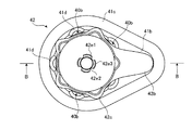
ところで、機能実行手段を備えるカプセル型内視鏡は、被検者への使用前には、滅菌されてその滅菌状態を保つ必要がある。そこで、この実施の形態では、上記のカプセル型内視鏡2を滅菌可能な収容ケースに収容している。以下に図4〜図12を用いて、実施の形態1にかかる収容ケースを説明する。ここで、図4は、このカプセル型内視鏡を収容する収容ケースの構成を示す斜視図であり、図5は、図4に示した収容ケースから滅菌シートを取り除いた場合の一例を示す斜視図であり、図6は、図5に示した収容ケースの上面を示す上面図であり、図7は、同じく収容ケースの側面を示す側面図であり、図8は、図5に示した実施の形態1にかかる中蓋部の上面を示す上面図であり、図9は、同じく実施の形態1にかかる中蓋部の側面を示す側面図であり、図10は、図9に示した孔部の拡大したA−A断面を示す断面図であり、図11は、図5に示した収容ケースの上面を示す上面図であり、図12は、図11のB−B断面を示す断面図である。
By the way, the capsule endoscope provided with the function execution means needs to be sterilized and kept in a sterilized state before being used for the subject. Therefore, in this embodiment, the
まず、図4および図5において、収容ケース40は、カプセル型内視鏡2を内部に収容可能な外部収容部からなるブリスターパック41と、ブリスターパック41内に備えられ、ブリスターパック41との間でカプセル型内視鏡2を保持する内部収容部からなる中蓋部42と、ブリスターパック41の上面に設けられて、ブリスターパック41の開口を閉塞する滅菌シート43とを備える。なお、ブリスターパック41と中蓋部42とは、第1および第2の保持手段を構成している。
First, in FIGS. 4 and 5, the
ブリスターパック41は、図6および図7に示すように、有底の円筒部41aと、この円筒部41aの開口上縁の一部に設けられた舌片形状の取手部41bと、この円筒部41aの開口上縁および取手部41bの外周に設けられた縁部41cと、円筒部41aの周面に設けられ、円筒部41aの内部から外部方向に突出した略半円柱形状の複数の突起部41dとを備える。
As shown in FIGS. 6 and 7, the
この円筒部41aは、底面41eを有し、この底面41eは、円筒部41aの外周側に設けられた外側底面41e1と、この外側底面41e1の略中央部分に設けられた内側底面41e2とからなる。内側底面41e2は、所定半径の円盤形状に形成され、外側底面41e1は、内側底面41e2の位置から円筒部41aの外部(開口方向と逆方向)に向けて突出した底面からなり、下面が所定の幅を有する中空のドーナツ形状に形成されている。この外側底面41e1と内側底面41e2との間には、図7に示すように、高低差Dが生じている。また、内側底面41e2の中央部分には、内側底面41e2の位置から外側底面41e1方向に向けて窪んだ略半球形状の保持部41e3が設けられている。この保持部41e3は、カプセル型内視鏡2の胴部カバー11bを構成するドーム形状の後端部を保持するためのもので、内側には開口方向に向って十文字形状の突起部41e4が設けられ、線接触で保持された胴部カバー11bの後端部へ滅菌ガスが侵入して、この後端部全体をムラなく滅菌することを可能にしている。なお、この突起部41e4は、複数の突起で構成し、後端部をそれぞれ点接触で保持するように構成することも可能である。
The
取手部41bは、上面が略三角形状の板状部材からなり、図5に示すように、後述する中蓋部42の取手部42bが当接可能に構成されている。縁部41cは、所定の幅を有し、円筒部41aの開口上縁および取手部41bの外周に、階段状に1段高く設けられ、取手部41bに当接した中蓋部42の取手部の動きを抑制している。また、この縁部41cの高さは、取手部41bに当接した中蓋部42の取手部42bや縁部42cの厚みと同等以上に構成されており、この中蓋部42がブリスターパック41内に収容された状態で、縁部41cの上面に滅菌シート43の貼り付けを可能にしている。
The
この突起部41dは、円筒部41aの長手方向に設けられた略半円柱形状の突起からなり、上端(円筒部41aの開口側)の径が最も大きく下端(底面41e側)にいくにしたがって径が徐々に小さくなるように構成され、かつ円筒部41aの長手方向に沿ってそれぞれが略等間隔に配置されている。この突起部41dは、上端が開口し、下端が半ドーム形状の底面を形成している。なお、この実施の形態では、円筒部41aの周面に5つの突起部41dがそれぞれ略等間隔に配置されている。
The
中蓋部42は、図8および図9に示すように、有底の円筒部42aと、この円筒部42aの開口上縁の一部に設けられた舌片形状の取手部42bと、この円筒部41aの開口上縁に取手部42bと連なるように設けられた縁部42cと、円筒部42aの内部から外部方向に突出した略半円柱形状の複数の突起部42dとを備える。
As shown in FIGS. 8 and 9, the
この円筒部42aは、図8〜図12に示すように、底面42eを有し、この底面42eの中央部分には、カプセル型内視鏡2を保持するための孔部42e1が設けられている。この孔部42e1は、底面42eの位置から円筒部42aの内部(開口方向)に向けて突出した上面を有する略円筒の断面凸形状に形成されており、その内径は、カプセル型内視鏡2の外径より若干大きい内径で構成されている。この孔部42e1の内周には、孔部42e1の開口に向う長手方向に直線状の突起42e2が複数、この実施の形態では4つ形成されている。また、この孔部42e1の上面側には、段差部42e3が設けられており、この段差部42e3の内径は、孔部42e1の開口側の内径よりも、小さい径で構成されている。図12に示すように、中蓋部42がブリスターパック41内に収容された時に、この円筒部42aの孔部42e1を含む底面42eおよびブリスターパック41の保持部41e3を含む内側底面41e2は、本発明にかかる保持空間領域40aを形成しており、カプセル型内視鏡2を収容して保持することを可能としている。
As shown in FIGS. 8 to 12, the
この実施の形態では、図9、図12に示すように、孔部42e1にカプセル型内視鏡2の先端カバー11a側が挿入された時に、一点鎖線a,aの範囲内の鏡面仕上げ部11a1が突起42e2および段差部42e3を含む孔部42e1の構成部分と非接触な状態になるように、突起42e2が密閉容器11の胴部カバー11bの一部を線接触で保持するとともに、段差部42e3の先端部が先端カバー11aの一部を線接触で保持するように構成されている。なお、これら突起42e2は、孔部42e1の長手方向に直線状に形成させるものに限らず、たとえば孔部42e1に複数の突起部を設け、密閉容器11の胴部カバー11bの一部をそれぞれ点接触で保持するように構成することも可能である。
In this embodiment, as shown in FIGS. 9 and 12, when the
取手部42bは、上面が取手部41bより略小型の略三角形状の板状部材からなり、図8、図11に示すように、円筒部41aの開口上縁に設けられた縁部42cと一体的に形成されている。この取手部42bは、中蓋部42がブリスターパック41内に収容された時に、ブリスターパック41の取手部41bと当接可能に構成されている。また、縁部42cは、円筒部42aの開口上縁に設けられ、中蓋部42がブリスターパック41内に収容された時に、ブリスターパック41の開口上縁に当接可能に構成されている。上述したように、これら取手部42bおよび縁部42cの厚みは、ブリスターパック41の縁部41cの厚み以下に構成されている。そして、この中蓋部42がブリスターパック41内に収容された時に、この縁部41cによって取手部42bの動きが取手部41bの幅の範囲に制限されるとともに、縁部41cの上面に滅菌シート43が貼り付けられると、これら取手部42bおよび縁部42cを含む中蓋部42全体が、ブリスターパック41内に収容された状態になる。
The
突起部42dは、円筒部42aの長手方向に設けられた略半円柱形状の突起からなり、円筒部42aの長手方向に沿ってそれぞれが略等間隔に配置されている。この突起部42dは、上端が開口し、下端が半ドーム形状の底面を形成している。なお、この実施の形態では、円筒部42aの周面に5つの突起部42dがそれぞれ略等間隔に配置されている。これら突起部42dは、中蓋部42がブリスターパック41内に収容されて取手部41bと42bが当接した状態で、それぞれがブリスターパック41の突起部41dと対向しない位置で、かつ突起部42dの最突出部分が円筒部41aの内周面と接触可能に形成されて、ブリスターパック41内での中蓋部42のガタツキを防止している。
The
図5、図11、図12に示すように、ブリスターパック41の突起部41d内周面と、中蓋部42の円筒部42aの外周面との間には、本発明にかかる空隙による通路40bが形成されており、滅菌シート43を介して外部から侵入した滅菌ガスの通過を可能にしている。また、この通路40bと保持空間領域40aとは互いに連通しており、通路40bを通った滅菌ガスが保持空間領域40aへ到達するのを可能にしている。
As shown in FIGS. 5, 11, and 12, a
また、カプセル型内視鏡2は、内部に外部からの磁界によってオン/オフ動作を行う電源供給用のリードスイッチ(図示せず)を有しており、このリードスイッチのオン状態になって各機能実行手段に電源が供給されたことを、図2に示したLED20の点滅によって外部に知らしめる。そこで、使用時には、滅菌シート43を収容ケース40から剥離させ、中蓋部42の円筒部42a内側に磁性体(磁石)を収納し、この収納された磁性体の磁界によってリードスイッチをオン状態にし、透明または半透明の孔部42e1からLED20の点滅状態を確認することが可能となる。すなわち、孔部42e1は、カプセル型内視鏡2の保持および保護機能の他に、LEDの点滅確認を容易にするための機能を有している。
The
このように、この実施の形態では、中蓋部42がブリスターパック41内に収容された時に、製造されたカプセル型内視鏡2を、中蓋部42の底面42eとブリスターパック41の内側底面41e2とによって形成された保持空間領域40aに収容して、保持部41e3および孔部42e1で保持することでカプセル型内視鏡2を収容ケース40内にセットする。次に、この収容ケース40の開口に滅菌シート43をヒートシールした後に、収容ケース40全体をEOG滅菌にかけることで、収容ケース40内部の菌が滅菌され、点接触または線接触で保持空間領域40a内に保持されるカプセル型内視鏡2全体をムラなく、確実に滅菌状態にすることができる。また、この実施の形態では、ヒートシールされた滅菌シート43により新たな菌の収容ケース40内への侵入を防ぐことで、収容ケース内の滅菌状態を保持することができる。
Thus, in this embodiment, when the
また、被検者への使用時には、収容ケース40から滅菌シート43を剥離させて、たとえば滅菌済みの磁性体を中蓋部42の円筒部42a内側に収納して、カプセル型内視鏡2のリードスイッチをオンにし、電池29から各機能実行手段への電源供給を可能にする。次に、図13に示すように、中蓋部42の取手部42bを指で摘んで中蓋部42をブリスターパック41内から取り出すと、カプセル型内視鏡2は、誰の手にも触れられることなく、孔部42e1に保持された状態で取り出される。なお、中蓋部42の取り出しには、たとえば孔部42e1を中蓋部42の内側から指で摘んで取り出すことも可能である。
Further, when used for a subject, the
したがって、この実施の形態では、ブリスターパックと中蓋部間に通路およびこの通路に連通する保持空間領域を形成し、かつ形成された保持空間領域内にカプセル型内視鏡を収容して線接触で保持することで、カプセル型内視鏡を確実に保持できるとともに、この通路および保持空間領域を閉塞するように、滅菌ガス透過性を有する滅菌シートでブリスターパックの開口を閉塞するので、ガス滅菌時に、カプセル型内視鏡の接触部分にも通路および保持空間領域を介して滅菌ガスが侵入して、ガス滅菌が施され、これによって収容ケースに収容されたカプセル型内視鏡全体をムラなく、確実に滅菌することができる。 Therefore, in this embodiment, a passage and a holding space region communicating with the passage are formed between the blister pack and the inner lid portion, and the capsule endoscope is accommodated in the formed holding space region to make line contact. By holding the capsule endoscope, the capsule endoscope can be securely held, and the opening of the blister pack is closed with a sterilizing gas permeable sterilization sheet so as to close the passage and the holding space region. Occasionally, sterilization gas also enters the contact portion of the capsule endoscope through the passage and the holding space region, and gas sterilization is performed, so that the entire capsule endoscope housed in the housing case is evenly distributed. Can be sterilized reliably.
(実施の形態2)
図14は、図5に示した実施の形態2にかかる中蓋部の上面の一例を示す上面図である。なお、以下の図において、実施の形態1と同様の構成部分に関しては、説明の都合上、同一符号を付記するものとする。図において、中蓋部42は、孔部42e1の近隣の底面42eに複数の穴部42f、この実施の形態では、4つの穴部42fを設け、この穴部42fを介して中蓋部42の内側と外側の滅菌ガスの流通を可能にしている。この穴部42fは、孔部42e1に近い位置に設けることで、孔部42e1に保持されたカプセル型内視鏡2への滅菌ガスの到達を早め、より迅速にカプセル型内視鏡2全体をムラなく、確実に滅菌状態にすることができる。
(Embodiment 2)
FIG. 14 is a top view illustrating an example of the top surface of the inner lid portion according to the second embodiment illustrated in FIG. 5. In the following drawings, the same components as those in Embodiment 1 are denoted by the same reference numerals for convenience of explanation. In the figure, the
また、図15は、同じく、実施の形態2にかかる中蓋部の構成の他例を示す斜視図である。図において、この例では、孔部42e1の頭頂部に穴部42gを設け、この穴部42gを介して中蓋部42の内側と外側の滅菌ガスの流通を可能にしている。この穴部42gは、カプセル型内視鏡2が保持されている孔部42e1の頭頂部に設けられているので、さらにカプセル型内視鏡2への滅菌ガスの到達を早め、より迅速にカプセル型内視鏡2全体をムラなく、確実に滅菌状態にすることができる。
FIG. 15 is also a perspective view showing another example of the configuration of the inner lid portion according to the second embodiment. In the figure, in this example, a
なお、本発明では、この実施の形態の2例に限らず、たとえばこれら2例を組み合わせて底面42eと孔部42e1の頭頂部に穴部42f,42gを設けても良いし、孔部42e1の周面に上記と同様の穴部を設けることも可能である。これらの場合にも、実施の形態2と同様の効果を奏することができる。また、その他に中蓋部42の円筒部42aの周面に穴部を設けることも可能である。
The present invention is not limited to the two examples of this embodiment, and for example, these two examples may be combined to provide the
(実施の形態3)
図16は、図5に示した実施の形態3にかかる中蓋部の構成を示す斜視図である。図において、この実施の形態では、中蓋部42の取手部42bおよび縁部42cを除く部分、すなわち円筒部42a、底面42e、孔部42e1を網の目形状のメッシュで構成して、中蓋部42の内側と外側の滅菌ガスの流通を可能にしている。この実施の形態では、中蓋部42の主要部分が全てメッシュで構成されているので、さらにカプセル型内視鏡2への滅菌ガスの到達を早め、より迅速にカプセル型内視鏡2全体をムラなく、確実に滅菌状態にすることができる。
(Embodiment 3)
FIG. 16 is a perspective view illustrating a configuration of the inner lid portion according to the third embodiment illustrated in FIG. 5. In this embodiment, in this embodiment, the portion other than the
なお、本発明では、この実施の形態に限らず、たとえば円筒部42aの周面のみ、底面のみ、または孔部のみをメッシュで構成することも可能であるし、またこれらを組み合わせて構成することも可能である。
In the present invention, not limited to this embodiment, for example, only the peripheral surface, only the bottom surface, or only the hole portion of the
1 被検体
2 カプセル型内視鏡
3 受信装置
4 表示装置
5 携帯型記録媒体
11 密閉容器
11a 先端カバー
11a1 鏡面仕上げ部
11b 胴部カバー
20 発光素子(LED)
21 LED駆動回路
22 固体撮像素子
23 CCD駆動回路
24 RF送信ユニット
25 送信アンテナ部
26 システムコントロール回路
27 結像レンズ
29 電池
31 受信ジャケット
32 外部装置
40 収容ケース
40a 保持空間領域
40b 通路
41 ブリスターパック
41a,42a 円筒部
41b,42b 取手部
41c,42c 縁部
41d,42d 突起部
41e,42e 底面
41e1 外側底面
41e2 内側底面
41e3 保持部
41e4 突起部
42 中蓋部
42e1 孔部
42e2 突起
42e3 段差部
42f,42g 穴部
43 滅菌シート
DESCRIPTION OF SYMBOLS 1
DESCRIPTION OF
Claims (8)
前記ブリスターパック内に収容され、前記ブリスターパックとの間に前記被検体内情報取得装置を保持するための保持空間領域を形成し、前記保持空間領域内に前記被検体内情報取得装置を収容して保持する中蓋部と、
前記収容空間を閉塞し、滅菌ガス透過性を有する滅菌シートと、
を備え、
前記中蓋部を前記ブリスターパックから取り出した際に、前記被検体内情報取得装置が前記中蓋部に保持された状態で取り出されることを特徴とする被検体内情報取得装置の収容ケース。 A blister pack forming a storage space for storing the in-subject information acquisition device;
Wherein is accommodated in the blister pack, said to form a holding space region for holding the in-vivo information acquiring apparatus, the accommodating intra-subject information acquiring apparatus to the holding space region between the blister pack Holding the inner lid ,
A sterilization sheet that closes the housing space and has sterilization gas permeability;
Equipped with a,
When the inner lid part was removed from the blister pack, the housing case of the in-vivo information acquiring apparatus according to claim Rukoto retrieved in a state where the in-vivo information acquiring apparatus is held in said lid.
前記中蓋部の底面には、前記筒部の内側に向けて突出した孔部であって、前記保持空間領域を形成して前記被検体内情報取得装置を保持する孔部が設けられていることを特徴とする請求項1に記載の被検体内情報取得装置の収容ケース。On the bottom surface of the inner lid portion, there is provided a hole portion that protrudes toward the inside of the cylinder portion and that forms the holding space region and holds the in-vivo information acquiring apparatus. The housing case for the in-vivo information acquiring apparatus according to claim 1.
前記中蓋部は、前記カプセル型内視鏡を、該カプセル型内視鏡の長手方向の一部を収容して保持することを特徴とする請求項1〜7のいずれか一つに記載の被検体内情報取得装置の収容ケース。 The in-vivo information acquiring apparatus, Ri capsule endoscope der that acquires image information inside the subject,
Wherein in the lid, wherein the capsule endoscope, to any one of claims 1 to 7, characterized that you receive and retain a portion of the longitudinal direction of the capsule endoscope Storage case for the in-subject information acquisition apparatus.
Priority Applications (6)
| Application Number | Priority Date | Filing Date | Title |
|---|---|---|---|
| JP2005000933A JP4611034B2 (en) | 2005-01-05 | 2005-01-05 | In-subject information acquisition device storage case |
| PCT/JP2005/022791 WO2006073041A1 (en) | 2005-01-05 | 2005-12-12 | Storage case for capsule type endoscope |
| EP05814177.1A EP1834569B1 (en) | 2005-01-05 | 2005-12-12 | Storage case for capsule type endoscope |
| US11/631,246 US7766167B2 (en) | 2005-01-05 | 2005-12-12 | Capsule endoscope storage case |
| AU2005323706A AU2005323706B2 (en) | 2005-01-05 | 2005-12-12 | Storage case for capsule type endoscope |
| CN2005800401222A CN101065047B (en) | 2005-01-05 | 2005-12-12 | Storage case for capsule type endoscope |
Applications Claiming Priority (1)
| Application Number | Priority Date | Filing Date | Title |
|---|---|---|---|
| JP2005000933A JP4611034B2 (en) | 2005-01-05 | 2005-01-05 | In-subject information acquisition device storage case |
Publications (3)
| Publication Number | Publication Date |
|---|---|
| JP2006187425A JP2006187425A (en) | 2006-07-20 |
| JP2006187425A5 JP2006187425A5 (en) | 2008-01-24 |
| JP4611034B2 true JP4611034B2 (en) | 2011-01-12 |
Family
ID=36647526
Family Applications (1)
| Application Number | Title | Priority Date | Filing Date |
|---|---|---|---|
| JP2005000933A Expired - Fee Related JP4611034B2 (en) | 2005-01-05 | 2005-01-05 | In-subject information acquisition device storage case |
Country Status (6)
| Country | Link |
|---|---|
| US (1) | US7766167B2 (en) |
| EP (1) | EP1834569B1 (en) |
| JP (1) | JP4611034B2 (en) |
| CN (1) | CN101065047B (en) |
| AU (1) | AU2005323706B2 (en) |
| WO (1) | WO2006073041A1 (en) |
Families Citing this family (12)
| Publication number | Priority date | Publication date | Assignee | Title |
|---|---|---|---|---|
| JP4546278B2 (en) * | 2005-02-16 | 2010-09-15 | オリンパス株式会社 | Capsule endoscope power starter |
| US7434691B2 (en) * | 2006-09-08 | 2008-10-14 | The Smartpill Corporation | Ingestible capsule packaging |
| US8128560B2 (en) * | 2006-10-31 | 2012-03-06 | Olympus Medical Systems Corp. | Power-supply starter apparatus for capsule-type medical device, start method of capsule-type medical device, and stop method of power supply for capsule-type medical device |
| US7931149B2 (en) * | 2009-05-27 | 2011-04-26 | Given Imaging Ltd. | System for storing and activating an in vivo imaging capsule |
| EP2471438A4 (en) * | 2010-03-05 | 2012-08-01 | Olympus Medical Systems Corp | Capsule-type endoscope startup system |
| CN102753081B (en) * | 2010-04-05 | 2015-06-24 | 奥林巴斯医疗株式会社 | Package for capsule medical device |
| CN103228196B (en) | 2011-05-13 | 2014-07-09 | 奥林巴斯医疗株式会社 | Storage case for capsule-type endoscope, capsule-type endoscope kit, method for assembling capsule-type endoscope kit, and device for assembling capsule-type endoscope kit |
| JP6177315B2 (en) * | 2012-05-19 | 2017-08-09 | キャプソ・ヴィジョン・インコーポレーテッド | Optical wireless docking system for capsule camera |
| US9943641B2 (en) * | 2013-03-14 | 2018-04-17 | Becton, Dickinson And Company | Package for medical product |
| CN109229744A (en) * | 2018-09-28 | 2019-01-18 | 深圳市资福医疗技术有限公司 | It is a kind of to seal fungi-proofing capsule endoscope packing device |
| DE102018125610A1 (en) * | 2018-10-16 | 2020-04-16 | Aesculap Ag | Absorbable packaging for a medical device |
| CN111467045A (en) | 2020-05-25 | 2020-07-31 | 安翰科技(武汉)股份有限公司 | Capsule endoscope packing plant |
Citations (15)
| Publication number | Priority date | Publication date | Assignee | Title |
|---|---|---|---|---|
| JPS60123372A (en) * | 1983-11-16 | 1985-07-02 | エチコン・インコーポレーテツド | Sealable vessel for packaging medical product under sterile state |
| US4697703A (en) * | 1986-07-02 | 1987-10-06 | Malcolm Will | Joint prosthesis package |
| US5219077A (en) * | 1992-02-10 | 1993-06-15 | Ethicon, Inc. | Package for mesh onlay and attached mesh plug technical field |
| JPH05212058A (en) * | 1992-02-07 | 1993-08-24 | Nikon Corp | Medical material storage case |
| JPH07187249A (en) * | 1993-10-18 | 1995-07-25 | Ethicon Inc | Sterilized packaged product |
| JPH10286263A (en) * | 1997-04-11 | 1998-10-27 | Olympus Optical Co Ltd | Endoscopic treatment tool housing case |
| JPH11193010A (en) * | 1997-12-26 | 1999-07-21 | Seikagaku Kogyo Co Ltd | Pasteurization method in medical pasteurization packaging |
| JP2000060791A (en) * | 1998-08-26 | 2000-02-29 | Olympus Optical Co Ltd | Endoscope tray |
| JP2000185055A (en) * | 1998-12-24 | 2000-07-04 | Junji Suwata | Disposable operation instrument set |
| JP2002017824A (en) * | 2000-06-30 | 2002-01-22 | Olympus Optical Co Ltd | High-temperature and high-pressure steam sterilizing vessel |
| JP2002034890A (en) * | 2000-07-28 | 2002-02-05 | Olympus Optical Co Ltd | Endoscope |
| JP2003116773A (en) * | 2002-02-18 | 2003-04-22 | Olympus Optical Co Ltd | Hood member mounting tool |
| JP2003523795A (en) * | 1999-11-15 | 2003-08-12 | ギブン・イメージング・リミテツド | How to launch the image acquisition process |
| US20030168370A1 (en) * | 2002-03-08 | 2003-09-11 | Barbara L. Merboth | Package with insert for holding allograft implant to preclude lipid transfer |
| JP2004261240A (en) * | 2003-02-25 | 2004-09-24 | Olympus Corp | Capsule type medical instrument |
Family Cites Families (14)
| Publication number | Priority date | Publication date | Assignee | Title |
|---|---|---|---|---|
| US4124141A (en) * | 1977-07-11 | 1978-11-07 | Armentrout James L | Sterile container |
| US4915913A (en) * | 1984-05-22 | 1990-04-10 | Genesis Medical Corporation | Medical sterilizer device with improved latch mechanism |
| CN86208639U (en) | 1986-11-04 | 1987-12-23 | 谢世庚 | Combining sterilized box for injector |
| US5082112A (en) * | 1991-02-05 | 1992-01-21 | United States Surgical Corporation | Package for endoscopic ligating instrument |
| US5144942A (en) * | 1991-03-21 | 1992-09-08 | United States Surgical Corporation | Endoscopic instrumentation kit and package therefor |
| US5165539A (en) * | 1991-12-19 | 1992-11-24 | Kimberly-Clark Corporation | Surgical instrument transport tray |
| US5221007A (en) * | 1992-02-19 | 1993-06-22 | Plastofilm Industries Inc. | Telescoping capsule package for suporting fragile article |
| EP0560470A1 (en) * | 1992-03-07 | 1993-09-15 | Oxley Developments Company Limited | Personnel identification devices |
| US5246109A (en) * | 1992-05-22 | 1993-09-21 | Biomedical Sensors, Ltd. | Package for an active medical device |
| US5379895A (en) * | 1993-09-13 | 1995-01-10 | Minnesota Mining And Manufacturing Company | Package for surgical device |
| IL108352A (en) * | 1994-01-17 | 2000-02-29 | Given Imaging Ltd | In vivo video camera system |
| US5590778A (en) * | 1995-06-06 | 1997-01-07 | Baxter International Inc. | Double-sterile package for medical apparatus and method of making |
| US6311838B1 (en) * | 1999-12-21 | 2001-11-06 | Cobe Cardiovascular, Inc. | Packaging system for medical components |
| US7291308B2 (en) * | 2004-08-27 | 2007-11-06 | Ethicon, Inc. | Endoscope immersion tray |
-
2005
- 2005-01-05 JP JP2005000933A patent/JP4611034B2/en not_active Expired - Fee Related
- 2005-12-12 CN CN2005800401222A patent/CN101065047B/en not_active Expired - Fee Related
- 2005-12-12 EP EP05814177.1A patent/EP1834569B1/en not_active Expired - Fee Related
- 2005-12-12 AU AU2005323706A patent/AU2005323706B2/en not_active Ceased
- 2005-12-12 WO PCT/JP2005/022791 patent/WO2006073041A1/en active Application Filing
- 2005-12-12 US US11/631,246 patent/US7766167B2/en active Active
Patent Citations (15)
| Publication number | Priority date | Publication date | Assignee | Title |
|---|---|---|---|---|
| JPS60123372A (en) * | 1983-11-16 | 1985-07-02 | エチコン・インコーポレーテツド | Sealable vessel for packaging medical product under sterile state |
| US4697703A (en) * | 1986-07-02 | 1987-10-06 | Malcolm Will | Joint prosthesis package |
| JPH05212058A (en) * | 1992-02-07 | 1993-08-24 | Nikon Corp | Medical material storage case |
| US5219077A (en) * | 1992-02-10 | 1993-06-15 | Ethicon, Inc. | Package for mesh onlay and attached mesh plug technical field |
| JPH07187249A (en) * | 1993-10-18 | 1995-07-25 | Ethicon Inc | Sterilized packaged product |
| JPH10286263A (en) * | 1997-04-11 | 1998-10-27 | Olympus Optical Co Ltd | Endoscopic treatment tool housing case |
| JPH11193010A (en) * | 1997-12-26 | 1999-07-21 | Seikagaku Kogyo Co Ltd | Pasteurization method in medical pasteurization packaging |
| JP2000060791A (en) * | 1998-08-26 | 2000-02-29 | Olympus Optical Co Ltd | Endoscope tray |
| JP2000185055A (en) * | 1998-12-24 | 2000-07-04 | Junji Suwata | Disposable operation instrument set |
| JP2003523795A (en) * | 1999-11-15 | 2003-08-12 | ギブン・イメージング・リミテツド | How to launch the image acquisition process |
| JP2002017824A (en) * | 2000-06-30 | 2002-01-22 | Olympus Optical Co Ltd | High-temperature and high-pressure steam sterilizing vessel |
| JP2002034890A (en) * | 2000-07-28 | 2002-02-05 | Olympus Optical Co Ltd | Endoscope |
| JP2003116773A (en) * | 2002-02-18 | 2003-04-22 | Olympus Optical Co Ltd | Hood member mounting tool |
| US20030168370A1 (en) * | 2002-03-08 | 2003-09-11 | Barbara L. Merboth | Package with insert for holding allograft implant to preclude lipid transfer |
| JP2004261240A (en) * | 2003-02-25 | 2004-09-24 | Olympus Corp | Capsule type medical instrument |
Also Published As
| Publication number | Publication date |
|---|---|
| US20080039675A1 (en) | 2008-02-14 |
| JP2006187425A (en) | 2006-07-20 |
| EP1834569A1 (en) | 2007-09-19 |
| CN101065047B (en) | 2010-05-05 |
| EP1834569B1 (en) | 2017-07-12 |
| CN101065047A (en) | 2007-10-31 |
| US7766167B2 (en) | 2010-08-03 |
| AU2005323706B2 (en) | 2008-12-04 |
| EP1834569A4 (en) | 2011-11-23 |
| AU2005323706A1 (en) | 2006-07-13 |
| WO2006073041A1 (en) | 2006-07-13 |
Similar Documents
| Publication | Publication Date | Title |
|---|---|---|
| JP4546278B2 (en) | Capsule endoscope power starter | |
| US7766167B2 (en) | Capsule endoscope storage case | |
| EP1834568B1 (en) | Capsule endoscope storage case | |
| JP5277321B2 (en) | Power supply starter for capsule medical devices | |
| WO2008053893A1 (en) | Starter device for electric power source for capsule-type medical device, method of starting capsule-type medical device, and method of stopping electric power source | |
| JP4520352B2 (en) | Storage case for wireless in-vivo information acquisition device | |
| JP4632734B2 (en) | Capsule endoscope power starter | |
| JP4611091B2 (en) | In-subject information acquisition device storage case | |
| JP4579038B2 (en) | Storage case for wireless in-vivo information acquisition device | |
| JP4520266B2 (en) | Capsule endoscope storage case | |
| JP4579005B2 (en) | In-subject information acquisition device storage case | |
| JP4472401B2 (en) | In-subject information acquisition device |
Legal Events
| Date | Code | Title | Description |
|---|---|---|---|
| A521 | Request for written amendment filed |
Free format text: JAPANESE INTERMEDIATE CODE: A523 Effective date: 20071205 |
|
| A621 | Written request for application examination |
Free format text: JAPANESE INTERMEDIATE CODE: A621 Effective date: 20071205 |
|
| A131 | Notification of reasons for refusal |
Free format text: JAPANESE INTERMEDIATE CODE: A131 Effective date: 20100601 |
|
| A521 | Request for written amendment filed |
Free format text: JAPANESE INTERMEDIATE CODE: A523 Effective date: 20100802 |
|
| TRDD | Decision of grant or rejection written | ||
| A01 | Written decision to grant a patent or to grant a registration (utility model) |
Free format text: JAPANESE INTERMEDIATE CODE: A01 Effective date: 20100928 |
|
| A01 | Written decision to grant a patent or to grant a registration (utility model) |
Free format text: JAPANESE INTERMEDIATE CODE: A01 |
|
| A61 | First payment of annual fees (during grant procedure) |
Free format text: JAPANESE INTERMEDIATE CODE: A61 Effective date: 20101013 |
|
| FPAY | Renewal fee payment (event date is renewal date of database) |
Free format text: PAYMENT UNTIL: 20131022 Year of fee payment: 3 |
|
| R151 | Written notification of patent or utility model registration |
Ref document number: 4611034 Country of ref document: JP Free format text: JAPANESE INTERMEDIATE CODE: R151 |
|
| FPAY | Renewal fee payment (event date is renewal date of database) |
Free format text: PAYMENT UNTIL: 20131022 Year of fee payment: 3 |
|
| S531 | Written request for registration of change of domicile |
Free format text: JAPANESE INTERMEDIATE CODE: R313531 |
|
| R350 | Written notification of registration of transfer |
Free format text: JAPANESE INTERMEDIATE CODE: R350 |
|
| R250 | Receipt of annual fees |
Free format text: JAPANESE INTERMEDIATE CODE: R250 |
|
| R250 | Receipt of annual fees |
Free format text: JAPANESE INTERMEDIATE CODE: R250 |
|
| R250 | Receipt of annual fees |
Free format text: JAPANESE INTERMEDIATE CODE: R250 |
|
| R250 | Receipt of annual fees |
Free format text: JAPANESE INTERMEDIATE CODE: R250 |
|
| LAPS | Cancellation because of no payment of annual fees |