JP4600524B2 - Development device - Google Patents
Development device Download PDFInfo
- Publication number
- JP4600524B2 JP4600524B2 JP2008151790A JP2008151790A JP4600524B2 JP 4600524 B2 JP4600524 B2 JP 4600524B2 JP 2008151790 A JP2008151790 A JP 2008151790A JP 2008151790 A JP2008151790 A JP 2008151790A JP 4600524 B2 JP4600524 B2 JP 4600524B2
- Authority
- JP
- Japan
- Prior art keywords
- toner
- supply
- roller
- developing device
- region
- Prior art date
- Legal status (The legal status is an assumption and is not a legal conclusion. Google has not performed a legal analysis and makes no representation as to the accuracy of the status listed.)
- Expired - Fee Related
Links
Images


Classifications
-
- G—PHYSICS
- G03—PHOTOGRAPHY; CINEMATOGRAPHY; ANALOGOUS TECHNIQUES USING WAVES OTHER THAN OPTICAL WAVES; ELECTROGRAPHY; HOLOGRAPHY
- G03G—ELECTROGRAPHY; ELECTROPHOTOGRAPHY; MAGNETOGRAPHY
- G03G15/00—Apparatus for electrographic processes using a charge pattern
- G03G15/06—Apparatus for electrographic processes using a charge pattern for developing
- G03G15/08—Apparatus for electrographic processes using a charge pattern for developing using a solid developer, e.g. powder developer
- G03G15/0806—Apparatus for electrographic processes using a charge pattern for developing using a solid developer, e.g. powder developer on a donor element, e.g. belt, roller
- G03G15/0808—Apparatus for electrographic processes using a charge pattern for developing using a solid developer, e.g. powder developer on a donor element, e.g. belt, roller characterised by the developer supplying means, e.g. structure of developer supply roller
-
- G—PHYSICS
- G03—PHOTOGRAPHY; CINEMATOGRAPHY; ANALOGOUS TECHNIQUES USING WAVES OTHER THAN OPTICAL WAVES; ELECTROGRAPHY; HOLOGRAPHY
- G03G—ELECTROGRAPHY; ELECTROPHOTOGRAPHY; MAGNETOGRAPHY
- G03G15/00—Apparatus for electrographic processes using a charge pattern
- G03G15/06—Apparatus for electrographic processes using a charge pattern for developing
- G03G15/08—Apparatus for electrographic processes using a charge pattern for developing using a solid developer, e.g. powder developer
- G03G15/0806—Apparatus for electrographic processes using a charge pattern for developing using a solid developer, e.g. powder developer on a donor element, e.g. belt, roller
- G03G15/081—Apparatus for electrographic processes using a charge pattern for developing using a solid developer, e.g. powder developer on a donor element, e.g. belt, roller characterised by the developer handling means after the supply and before the regulating, e.g. means for preventing developer blocking
-
- G—PHYSICS
- G03—PHOTOGRAPHY; CINEMATOGRAPHY; ANALOGOUS TECHNIQUES USING WAVES OTHER THAN OPTICAL WAVES; ELECTROGRAPHY; HOLOGRAPHY
- G03G—ELECTROGRAPHY; ELECTROPHOTOGRAPHY; MAGNETOGRAPHY
- G03G2215/00—Apparatus for electrophotographic processes
- G03G2215/08—Details of powder developing device not concerning the development directly
- G03G2215/0855—Materials and manufacturing of the developing device
- G03G2215/0866—Metering member
Description
この発明は現像装置に関し、より詳しくは、複写機、プリンタ等の電子写真方式の画像形成装置に用いられる現像装置に関する。 The present invention relates to a developing device, and more particularly to a developing device used in an electrophotographic image forming apparatus such as a copying machine or a printer.
一般的に、電子写真方式の画像形成装置では、感光体を露光してその感光体の表面に静電潜像を形成し、その静電潜像を現像装置によって現像してその感光体の表面にトナー像を形成し、そのトナー像を記録媒体としてのシートに転写および定着させる。 In general, in an electrophotographic image forming apparatus, a photosensitive member is exposed to form an electrostatic latent image on the surface of the photosensitive member, and the electrostatic latent image is developed by a developing device. Then, a toner image is formed, and the toner image is transferred and fixed on a sheet as a recording medium.
この種の現像装置として、例えば特許文献1(特開2006−98854号公報)、特許文献2(特開2006−98855号公報)には、ケース、感光体にトナーを搬送する現像ローラ、現像ローラに圧接されてトナーを供給する供給ローラ、トナーを規制する規制ブレード、トナーを攪拌して搬送するトナー攪拌搬送部材、および、トナー攪拌搬送部材によって搬送されたトナーを受けて供給ローラの方へ案内するトナー受け部材を備えたものが記載されている。現像ローラは感光体に略接するようにケースの開口に配設される一方、供給ローラ、規制ブレード、トナー攪拌搬送部材およびトナー受け部材はいずれもケース内に配設されている。現像ローラと供給ローラとは、それぞれの中心軸の周りに互いに同じ向きに回転し、その結果、現像ローラと供給ローラとの間のニップ部ではそれぞれの外周面が互いに逆向き(カウンタの向き)に摺動する。規制ブレードは、上記ケース内で上記現像ローラのうち上記ニップ部よりも下方の部分に接して、上記供給ローラから供給された上記現像ローラ上のトナーを規制する。 As this type of developing device, for example, Patent Document 1 (Japanese Patent Laid-Open No. 2006-98854) and Patent Document 2 (Japanese Patent Laid-Open No. 2006-98855) describe a developing roller that conveys toner to a case, a photoreceptor, and a developing roller. A supply roller that is pressed against the toner and supplies a toner, a regulating blade that regulates the toner, a toner agitation conveyance member that agitates and conveys the toner, and a toner that is conveyed by the toner agitation conveyance member, and guides it toward the supply roller And a toner receiving member is described. The developing roller is disposed in the opening of the case so as to be substantially in contact with the photosensitive member, while the supply roller, the regulating blade, the toner stirring and conveying member, and the toner receiving member are all disposed in the case. The developing roller and the supply roller rotate in the same direction around the respective central axes. As a result, the outer peripheral surfaces of the nip portion between the developing roller and the supply roller are opposite to each other (counter direction). To slide. The regulating blade is in contact with a portion below the nip portion of the developing roller within the case and regulates the toner on the developing roller supplied from the supply roller.
特許文献3(特開2007−3889号公報)、特許文献4(特開2002−24437号公報)、特許文献5(特開2003−107903号公報)にも、現像ローラと供給ローラとのニップ部の下方にトナー攪拌搬送部材に相当する部材(それぞれパドル、アジテータ、搬送羽根と呼ばれる。以下「トナー攪拌搬送部材等」という。)が配設された、概ね同様の構成をもつ現像装置が開示されている。
上述のように、現像ローラと供給ローラとがそれらの間のニップ部で互いに逆向きに摺動している場合、現像ローラと供給ローラとのニップ部直下の領域(現像ローラの表面と供給ローラの表面とで挟まれた略三角形の領域)でトナーパッキングが発生する傾向がある。トナーパッキングが発生すると、現像ローラや供給ローラを駆動する歯車が回り難くなり、歯車がガタついて画質劣化や歯車の破壊が引き起こされる場合がある。 As described above, when the developing roller and the supply roller slide in opposite directions at the nip portion between them, the region immediately below the nip portion between the developing roller and the supply roller (the surface of the developing roller and the supply roller) There is a tendency for toner packing to occur in a substantially triangular region sandwiched between the surface of the toner. When toner packing occurs, the gears that drive the developing roller and the supply roller are difficult to rotate, and the gears may rattle and cause image quality degradation and gear destruction.
上記各特許文献の現像装置では、トナー攪拌搬送部材等は、現像ローラと供給ローラとのニップ部の下方に配設されて、現像ローラと供給ローラとのニップ部から下方へ自重で落ちるトナーを、上方に配設されたトナー受け部材へ搬送する。このように、現像ローラと供給ローラとのニップ部の下方にトナーが落ちる比較的広い空間を設けておくことで、現像ローラと供給ローラとのニップ部直下の領域でトナーパッキングが発生するのを防止している。 In the developing devices of each of the above patent documents, the toner agitating / conveying member is disposed below the nip portion between the developing roller and the supply roller, and removes the toner that falls by its own weight from the nip portion between the developing roller and the supply roller. Then, the toner is conveyed to a toner receiving member disposed above. In this way, by providing a relatively wide space where the toner falls below the nip portion between the developing roller and the supply roller, toner packing occurs in the region immediately below the nip portion between the developing roller and the supply roller. It is preventing.
しかしながら、上記各特許文献に開示されたようなトナー攪拌搬送部材等(駆動源によって駆動される)を備えた場合、現像装置の構成が大型で複雑になるという問題がある。 However, when the toner agitating / conveying member or the like (driven by a driving source) as disclosed in each of the above patent documents is provided, there is a problem that the configuration of the developing device is large and complicated.
そこで、この発明の課題は、トナーパッキングの発生を防止でき、しかも小型かつ簡単に構成できる現像装置を提供することにある。 SUMMARY OF THE INVENTION An object of the present invention is to provide a developing device that can prevent the occurrence of toner packing and that can be configured in a small and simple manner.
上記課題を解決するため、この発明の現像装置は、
非磁性1成分のトナーを収容したハウジングと、
このハウジングの開口に水平方向に延在する現像ローラと、
上記ハウジング内で上記現像ローラに対して平行に圧接されて第1のニップ部を形成し、上記現像ローラの回転の向きと同じ向きに回転して上記現像ローラへトナーを供給する供給ローラと、
上記ハウジング内に設置され、上記供給ローラのうち上記第1のニップ部よりも回転方向上流側の下方の部分に接して第2のニップ部を形成し、上記供給ローラから上記現像ローラへのトナーの供給量を規制する供給安定化部材とを備え、この供給安定化部材は、上記現像ローラのうち上記第1のニップ部よりも下方の部分と上記供給ローラのうち上記第1のニップ部よりも下方の部分とで挟まれた略三角形の第1領域から、上記第2のニップ部に関して上記第1領域とは反対の側まで延在し、
上記第1領域に溜まろうとするトナーの圧力によって、上記第1領域から、上記供給安定化部材の下方を通り、上記第2のニップ部に関して上記第1領域とは反対の側の上記供給安定化部材の上方に相当する第2領域まで、トナーが押し戻される流路であるトナー循環流路を備える。
In order to solve the above problems, the developing device of the present invention provides:
A housing containing non-magnetic single component toner;
A developing roller extending horizontally in the opening of the housing;
A supply roller that is pressed in parallel with the developing roller in the housing to form a first nip portion, rotates in the same direction as the developing roller, and supplies toner to the developing roller;
A toner is installed in the housing and forms a second nip portion in contact with a lower portion of the supply roller on the upstream side in the rotation direction than the first nip portion, and the toner from the supply roller to the developing roller A supply stabilizing member that regulates the supply amount of the developing roller, and the supply stabilizing member includes a portion below the first nip portion of the developing roller and a first nip portion of the supply roller. Extends from the substantially triangular first region sandwiched between the lower portion to the opposite side of the first region with respect to the second nip portion,
The supply stabilization on the side opposite to the first region with respect to the second nip portion from the first region and below the supply stabilization member due to the pressure of the toner to be accumulated in the first region. A toner circulation channel, which is a channel through which the toner is pushed back, is provided up to a second region corresponding to the upper part of the member.
ここで、「下方」、「上方」は、重力の方向に従って定まるものとする。 Here, “lower” and “upper” are determined according to the direction of gravity.
この発明の現像装置では、供給ローラが、現像ローラに対して平行に圧接されて第1のニップ部を形成し、上記現像ローラの回転の向きと同じ向きに回転する。すると、上記ハウジングに収容されているトナー、特に上記供給ローラの周囲に存在するトナーが上記供給ローラの回転に伴って搬送されて、上記第2領域から上記第2のニップ部へ送り込まれる。そして、この第2のニップ部で上記供給ローラから上記現像ローラへのトナーの供給量が規制される。上記供給ローラがさらに回転すると、上記第2のニップ部で規制されたトナーが搬送されて、上記供給ローラと上記現像ローラとの間の上記第1のニップ部へ送り込まれる。これにより、上記供給ローラから上記現像ローラへトナーが供給されて、上記現像ローラの外周面に担持される。上記現像ローラの外周面上のトナーは、上記現像ローラが回転することによって、例えば公知の規制部材によって規制された後、この現像装置の現像対象である感光体の表面の静電潜像を現像するのに用いられる。 In the developing device of the present invention, the supply roller is pressed in parallel with the developing roller to form the first nip portion, and rotates in the same direction as the rotation direction of the developing roller. Then, the toner accommodated in the housing, particularly the toner present around the supply roller, is conveyed along with the rotation of the supply roller, and is fed from the second region to the second nip portion. The second nip portion regulates the amount of toner supplied from the supply roller to the developing roller. When the supply roller further rotates, the toner regulated by the second nip portion is conveyed and sent to the first nip portion between the supply roller and the developing roller. Thus, the toner is supplied from the supply roller to the developing roller and is carried on the outer peripheral surface of the developing roller. The toner on the outer peripheral surface of the developing roller is regulated by, for example, a known regulating member as the developing roller rotates, and then develops the electrostatic latent image on the surface of the photoconductor that is the development target of the developing device. Used to do.
上記供給ローラが上記現像ローラへトナーを供給するとき、上記第1のニップ部で上記現像ローラに付着しなかったトナーは上記第1領域に溜まろうとする。ここで、この現像装置では、上記第1のニップ部で上記現像ローラに付着しなかったトナーは、上記第1領域に溜まろうとするトナーの圧力によって、トナー循環流路を通して、上記第1領域から、上記供給安定化部材の下方を通り、上記第1領域とは反対の側の上記供給安定化部材の上方に相当する第2領域まで、押し戻される。上記第2領域まで押し戻されたトナーは、上記供給ローラの回転に伴って、再び上記第2のニップ部へ送り込まれ、上記第1領域に達する。このようにして、上記トナー循環流路を通して、トナーが循環する。したがって、トナーパッキングの発生を防止できる。この結果、トナーパッキングに起因した画質劣化や歯車の破壊が引き起こされることがない。また、この現像装置では、トナーは、上記トナー循環流路を通して、上記第1領域に溜まろうとするトナーの圧力自体によって上記第2領域まで押し戻されるので、既述の各特許文献に開示されたようなトナー攪拌搬送部材等を設ける必要がない。したがって、この発明の現像装置は、小型かつ簡単に構成され得る。 When the supply roller supplies toner to the developing roller, the toner that has not adhered to the developing roller at the first nip portion tends to accumulate in the first region. Here, in this developing device, the toner that has not adhered to the developing roller at the first nip portion passes from the first region through the toner circulation channel due to the pressure of the toner that tends to accumulate in the first region. Then, it passes back below the supply stabilizing member and is pushed back to the second region corresponding to the upper side of the supply stabilizing member on the side opposite to the first region. The toner pushed back to the second region is sent again to the second nip portion as the supply roller rotates, and reaches the first region. In this way, the toner circulates through the toner circulation channel. Therefore, occurrence of toner packing can be prevented. As a result, image quality deterioration and gear destruction caused by toner packing are not caused. Further, in this developing device, the toner is pushed back to the second region by the pressure of the toner that is to be accumulated in the first region through the toner circulation flow path, so that it is disclosed in each of the aforementioned patent documents. It is not necessary to provide a toner agitating and conveying member. Therefore, the developing device of the present invention can be configured in a small and simple manner.
なお、上記ハウジング内で上記現像ローラのうち上記第1のニップ部よりも回転方向下流側の下方の部分に接して、上記現像ローラ上のトナーを規制する規制部材を備えるのが望ましい。 It is preferable that a regulating member for regulating toner on the developing roller is provided in contact with a lower portion of the developing roller on the downstream side in the rotation direction than the first nip portion in the housing.
上記規制部材および上記供給安定化部材は、上記各ローラの軸方向に沿って延在するのが望ましい。 It is desirable that the regulating member and the supply stabilizing member extend along the axial direction of each roller.
一実施形態の現像装置では、In the developing device of one embodiment,
上記供給安定化部材は、下方に向いた面である第1面と、上記第2のニップ部に関して上記第1領域とは反対の側の端面である第2面とを有し、The supply stabilizing member has a first surface that is a surface facing downward, and a second surface that is an end surface opposite to the first region with respect to the second nip portion,
上記ハウジングは、上記第1面に対向する第1の内壁面と、上記第2面に対向する第2の内壁面とを有しており、The housing has a first inner wall surface facing the first surface, and a second inner wall surface facing the second surface,
上記トナー循環流路は、上記供給安定化部材と、上記第1の内壁面及び上記第2の内壁面とによって挟まれた領域を含むことを特徴とする。The toner circulation flow path includes a region sandwiched between the supply stabilizing member, the first inner wall surface, and the second inner wall surface.
一実施形態の現像装置では、上記トナー循環流路の、上記トナーの流れる向きに垂直な断面の寸法が、実質的に一定であることを特徴とする。 In the developing device according to an embodiment, a dimension of a cross section of the toner circulation channel perpendicular to the toner flow direction is substantially constant.
この一実施形態の現像装置では、上記トナー循環流路の、上記トナーの流れる向きに垂直な断面の寸法が、実質的に一定であることから、上記トナー循環流路内でトナーが滞留し難くなる。したがって、上記トナー循環流路に沿ってトナーが循環し易くなり、トナーパッキングの発生をより確実に防止できる。 In the developing device of this embodiment, since the dimension of the cross section of the toner circulation channel perpendicular to the toner flow direction is substantially constant, the toner is difficult to stay in the toner circulation channel. Become. Therefore, the toner can easily circulate along the toner circulation flow path, and toner packing can be prevented more reliably.
一実施形態の現像装置では、上記トナー循環流路の、上記トナーの流れる向きに垂直な断面の寸法が、0.5mmを超えていることを特徴とする。 In the developing device according to one embodiment, a dimension of a cross section of the toner circulation channel perpendicular to the toner flow direction is more than 0.5 mm.
この一実施形態の現像装置では、上記トナー循環流路の、上記トナーの流れる向きに垂直な断面の寸法が、0.5mmを超えていることから、上記トナー循環流路内でトナーが滞留し難くなる。したがって、上記トナー循環流路に沿ってトナーが循環し易くなり、トナーパッキングの発生をより確実に防止できる。 In the developing device of this embodiment, since the dimension of the cross section of the toner circulation channel perpendicular to the toner flow direction exceeds 0.5 mm, the toner stays in the toner circulation channel. It becomes difficult. Therefore, the toner can easily circulate along the toner circulation flow path, and toner packing can be prevented more reliably.
一実施形態の現像装置では、上記トナー循環流路の上記第1領域から上記第2領域までの長さが5mmから20mmまでの範囲内にあることを特徴とする。 In one embodiment, the length of the toner circulation channel from the first region to the second region is in the range of 5 mm to 20 mm.
ここで、上記トナー循環流路の「長さ」とは、上記トナーの流れる向きに垂直な断面内で最短距離となるルートを通るときの長さを意味する。 Here, the “length” of the toner circulation channel means a length when passing through a route having the shortest distance in a cross section perpendicular to the direction in which the toner flows.
この一実施形態の現像装置では、上記トナー循環流路の上記第1領域から上記第2領域までの長さが5mmから20mmまでの範囲内にある。上記トナー循環流路の長さが5mmから20mmまでの範囲内にあるから、このトナー循環流路がトナーを循環させる流路として確実に機能する。なお、上記トナー循環流路の上記長さが短すぎると、上記第1領域から下方へのトナーの流れが有効に形成されず、上記トナーの循環が困難となる可能性がある。一方、上記トナー循環流路の上記長さが長すぎると、上記トナー循環流路の途中でトナーパッキングが発生する可能性が生ずる。 In the developing device of this embodiment, the length of the toner circulation channel from the first region to the second region is in the range of 5 mm to 20 mm. Since the length of the toner circulation channel is in the range from 5 mm to 20 mm, this toner circulation channel functions reliably as a channel for circulating toner. If the length of the toner circulation channel is too short, the toner flow downward from the first region is not effectively formed, and it may be difficult to circulate the toner. On the other hand, if the length of the toner circulation channel is too long, toner packing may occur in the middle of the toner circulation channel.
一実施形態の現像装置では、上記各ローラの中心軸に垂直な断面で、上記供給安定化部材の上記第1領域側の端部は上記現像ローラに接近するように上記第1領域の中央部まで延在していることを特徴とする。 In a developing device according to an embodiment, the central portion of the first region has a cross section perpendicular to the central axis of each roller, and an end portion of the supply stabilizing member on the first region side approaches the developing roller. It is characterized by extending to.
ここで「上記現像ローラに接近する」とは、上記供給安定化部材の上記第1領域側の端部は、上記供給安定化部材のうち上記供給ローラの下部に接する部分が屈曲して接近していても良い。 Here, “approaching the developing roller” means that the end of the supply stabilizing member on the first area side is bent and approaches the portion of the supply stabilizing member that contacts the lower portion of the supply roller. May be.
この一実施形態の現像装置では、上記各ローラの中心軸に垂直な断面で、上記供給安定化部材の上記第1領域側の端部は上記現像ローラに接近するように上記第1領域の中央部まで延在している。したがって、上記第1領域のうち上記現像ローラと上記供給ローラとの間の第1のニップ部近傍で発生したトナーが、上記供給安定化部材の上記端部の下方へ押し出され、その結果、上記トナー循環流路に沿ったトナーの流れが発生し易い。したがって、上記トナー循環流路がトナーを循環させる流路として確実に機能する。 In the developing device according to this embodiment, the supply stabilizing member has a cross section perpendicular to the central axis of each roller, and the end of the supply stabilizing member on the first region side approaches the developing roller. It extends to the department. Therefore, the toner generated in the vicinity of the first nip portion between the developing roller and the supply roller in the first region is pushed out below the end portion of the supply stabilization member, and as a result, A toner flow along the toner circulation channel is likely to occur. Therefore, the toner circulation channel functions reliably as a channel for circulating the toner.
一実施形態の現像装置では、上記各ローラは導電性材料からなる層を含み、上記供給安定化部材は導電性材料からなることを特徴とする。 In the developing device of one embodiment, each of the rollers includes a layer made of a conductive material, and the supply stabilizing member is made of a conductive material.
ここで「導電性材料」とは、例えば金属である。 Here, the “conductive material” is, for example, a metal.
この一実施形態の現像装置では、上記供給安定化部材は導電性材料からなるので、電位が制御され得る。上記供給安定化部材の電位を例えば上記供給ローラの電位と同じに制御してトナーを予備的に帯電させることで、上記供給ローラから上記現像ローラへのトナーの供給を安定化できる。 In the developing device of this embodiment, since the supply stabilizing member is made of a conductive material, the potential can be controlled. By controlling the potential of the supply stabilizing member to be equal to the potential of the supply roller, for example, and preliminarily charging the toner, the supply of toner from the supply roller to the developing roller can be stabilized.
一実施形態の現像装置では、上記供給安定化部材の上記第2領域側の端部は、上記第2のニップ部よりも上方に位置することを特徴とする。 In the developing device according to an embodiment, an end of the supply stabilizing member on the second region side is located above the second nip portion.
この一実施形態の現像装置では、上記供給安定化部材の上記第2領域側の端部は、上記第2のニップ部よりも上方に位置する。したがって、上記第2領域にトナーが溜まりやすくなる。この結果、上記供給ローラから上記現像ローラへのトナーの供給を安定化できる。 In the developing device according to this embodiment, the end portion on the second region side of the supply stabilizing member is located above the second nip portion. Therefore, toner tends to accumulate in the second region. As a result, the toner supply from the supply roller to the developing roller can be stabilized.
一実施形態の現像装置では、上記供給安定化部材のうち少なくとも上記第2のニップ部を形成する部分は、可撓性を示す板状に形成されていることを特徴とする。 In the developing device of one embodiment, at least a portion of the supply stabilizing member that forms the second nip portion is formed in a plate shape that exhibits flexibility.
この一実施形態の現像装置では、上記供給安定化部材のうち少なくとも上記第2のニップ部を形成する部分は、可撓性を示す板状に形成されている。したがって、上記供給ローラと上記供給安定化部材との間の接触の圧力が調節し易くなる。例えば、上記供給ローラが中心軸の周りに回転するとき、この供給ローラの外径振れや偏心、供給ローラの軸の振動によって、上記供給ローラと上記供給安定化部材との間の当接の仕方にばらつき要因が生じることがある。このようなばらつき要因が生じたとしても、この現像装置では、上記供給安定化部材がそのばらつきを吸収するように撓む。したがって、上記供給ローラと上記供給安定化部材との間の当接の仕方が安定する。この結果、上記供給ローラから上記現像ローラへのトナーの供給を安定化できる。 In the developing device of this embodiment, at least a portion of the supply stabilizing member that forms the second nip portion is formed in a plate shape that exhibits flexibility. Therefore, the contact pressure between the supply roller and the supply stabilization member can be easily adjusted. For example, when the supply roller rotates around the central axis, the supply roller and the supply stabilization member come into contact with each other due to the outer diameter fluctuation or eccentricity of the supply roller or the vibration of the supply roller shaft. Variation factors may occur. Even if such a variation factor occurs, in this developing device, the supply stabilizing member bends to absorb the variation. Therefore, the manner of contact between the supply roller and the supply stabilization member is stabilized. As a result, the toner supply from the supply roller to the developing roller can be stabilized.
以下、この発明を図示の実施の形態により詳細に説明する。 Hereinafter, the present invention will be described in detail with reference to the illustrated embodiments.
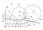
図1は、この発明の一実施形態の現像装置10を鉛直方向に切断したときの断面構造を示している。この現像装置10は、概略、現像ローラ36と、この現像ローラ36にトナーを供給するための供給ローラ38と、トナーの供給を安定化するための供給安定化部材70と、これらのローラ36,38および供給安定化部材70をトナー90と共に収容するハウジング32を備えている。
FIG. 1 shows a cross-sectional structure when a developing
トナー90としては、負極性に帯電する例えば非磁性1成分トナーが用いられ、必要に応じてチタン酸ストロンチウム等を含む外添剤が添加される。トナー90の直径は、特に限定されるものではないが、例えば6μm〜7μmである。なお、本発明は、正極性に帯電するトナーを用いることを妨げるものではない。
As the
ハウジング32には、図1の紙面に垂直な水平方向に延びるトナー供給用の開口部34が形成されている。
The
現像ローラ36は、ハウジング32の開口34を略塞ぐ態様で、図1の紙面に垂直な水平方向に延在している。供給ローラ38は、ハウジング32内で現像ローラ36に沿って略同じ高さレベルに設けられている。現像ローラ36と供給ローラ38は、互いに平行な図示しない回転軸を有し、自らの中心O1,O2の周りに回転可能に、かつ、互いに圧接された状態で設けられている。これにより、現像ローラ36と供給ローラ38は、第1のニップ部としてのニップ部66を形成している。現像ローラ36と供給ローラ38は、図示しないモータなどの駆動源に連結されており、その駆動源の駆動に基づいて図中に矢印d1,d2で示す反時計回りに回転するようになっている。その結果、現像ローラ36と供給ローラ38との間のニップ部66ではそれぞれの外周面が互いに逆向き(カウンタの向き)に摺動する。現像ローラ36と供給ローラ38の具体的な構成は後述する。
The developing
供給安定化部材70は、ハウジング32内で、供給ローラ38の最下部に沿って設置されている。供給安定化部材70は、図5に示すように、供給ローラ38の長手方向X(図1の紙面に垂直な水平方向)に沿って延びる水平板部71と、この水平板部71の片側(図1における左側)の側縁から上方へ延びる垂直板部72と、長手方向Xに関して水平板部71の両端に設けられたL字状の支持部74,75を有している。供給安定化部材70は、支持部74,75を介してハウジング32に固定されている。図1に示すように、供給安定化部材70の水平板部71は、供給ローラ38の最下部に対して下方から接した状態にある。これにより、供給安定化部材70の水平板部71と供給ローラ38とは、第2のニップ部としてのニップ部76を形成している。供給ローラ38に関して言えば、供給安定化部材70とのニップ部76は先に述べた現像ローラ36とのニップ部66よりも回転方向上流側に位置する。詳細には図示しないが、ニップ部76では、供給ローラ38は供給安定化部材70によって押し込まれて、自然状態から、この例では0.5mm程度凹んだ状態にある。
The
図1の断面では、この供給安定化部材70の水平板部71の図1における右側の端部71eは、現像ローラに接近するように、現像ローラ36のうちニップ部66よりも下方の部分と供給ローラ38のうちニップ部66よりも下方の部分とで挟まれた略三角形(または扇形)の領域(これを「第1領域」と呼ぶ。)21の略中央部まで延在している。供給安定化部材70の水平板部71は、その第1領域21から、ニップ部76に関して第1領域21とは反対の側(図1における左側)まで延びて、垂直板部72に連なっている。垂直板部72の上端72fは、ニップ部76よりも上方に位置している。この図1の断面で、ニップ部76に関して第1領域21とは反対の側で、供給安定化部材70の上方の領域、より詳しくは、水平板部71、垂直板部72および供給ローラ38で概ね囲まれた領域を、「第2領域」24と呼ぶ。
In the cross section of FIG. 1, an
この現像装置10では、第1領域21から、供給安定化部材70の水平板部71の下方、垂直板部72の図1における左側方を順次通り、第2領域24に達するトナー循環流路20が形成されている。水平板部71の下方には、水平板部71の下面と、その下面に対向するハウジング32の水平面32a(図2参照)とで仕切られた水平流路22が形成されている。また、垂直板部72の左側方には、垂直板部72の図1における左側面と、その左側面に対向するハウジング32の垂直面32b(図2参照)とで仕切られた垂直流路23が形成されている。トナー循環流路20は、第1領域21を、これらの水平流路22と垂直流路23を通して第2領域24に連通させている。
In the developing
ハウジング32内で開口部34の下縁近傍には、規制部材としての金属板からなる規制ブレード44が設けられている。規制ブレード44は、現像ローラ36のうちニップ部66よりも回転方向下流側の下方の部分に接して、現像ローラ36の外周面上のトナーを規制する。
A regulating
現像装置10はまた、スクリュウ等からなる2つの搬送部材40,42を有し、これら搬送部材40,42によって、ハウジング32内のトナー90が循環されるようになっている。
The developing
ハウジング32内の開口部34の上縁近傍には、除電手段50が設けられている。除電手段50は、現像ローラ36に当接する導電部材52と、導電部材52を現像ローラ36へ押し当てるための押し当て部材54を有する。
In the vicinity of the upper edge of the
現像ローラ36には、現像ローラ36に現像バイアスVDを印加するための電源56(現像バイアス印加手段)が接続されている。
The developing
導電部材52には、現像ローラ36上の極性と逆極性の除電バイアスVRを導電部材52に印加する電源58が接続されている。
The
この現像装置10では、供給ローラ38が矢印d2で示す反時計回りに回転すると、ハウジング32に収容されているトナー90、特に供給ローラ38の周囲に存在するトナーが供給ローラ38の回転に伴って搬送されて、第2領域24から、供給安定化部材70の水平板部71と供給ローラ38との間のニップ部76へ送り込まれる。そして、このニップ部76で供給ローラ38から現像ローラ36へのトナーの供給量が規制される。供給ローラ38がさらに回転すると、ニップ部76で規制されたトナーが搬送されて、供給ローラ38と現像ローラ36との間のニップ部(トナー供給・回収領域)66へ送り込まれる。これにより、供給ローラ38から現像ローラ36へトナーが供給されて、現像ローラ36の外周面に担持される。この際、現像ローラ36に供給されるトナーは、現像ローラ36と供給ローラ38との摩擦により予備帯電される。現像ローラ36が矢印d1で示す反時計回りに回転することによって、供給ローラ38から供給された現像ローラ36の外周面上のトナーは、現像ローラ36と規制ブレード44との接触部へ送り込まれる。そして、この規制ブレード44によって、現像ローラ36の外周面上のトナーは、層厚が規制されるとともに、規制ブレード44との摩擦接触により更に帯電される。現像ローラ36がさらに回転すると、現像ローラ36の外周面上の規制および帯電を受けたトナーは、感光体4と現像ローラ36とが対向する現像領域68に達する。現像領域68に達したトナーは、感光体4が担持する静電潜像(作像部分)に付着して、感光体4の外周面にトナー像を形成する。
In the developing
現像領域68を通過後、現像に供されずに現像ローラ36の外周面上に残されたトナーは、現像ローラ36の回転に伴って、現像ローラ36と導電部材52との接触部に達し、この導電部材52により除電されて現像ローラ36から剥離されやすい状態になる。この後、その剥離されやすい状態になったトナーは、現像ローラ36の回転に伴って供給ローラ38と現像ローラ36との間のニップ部66に達し、供給ローラ38によって回収される。
The toner remaining on the outer peripheral surface of the developing
さて、供給ローラ38から現像ローラ36へ上述のニップ部66でトナーが供給されるとき、現像ローラ36に付着しなかったトナーは第1領域21に溜まろうとする。この現像装置10では、上記ニップ部66で現像ローラ36に付着しなかったトナーは、第1領域21に溜まろうとするトナーの圧力によって、第1領域21から、トナー循環流路20を通して、第2領域24まで押し戻される。すなわち、トナーは、第1領域21から、供給安定化部材70の水平板部71の下方の水平流路22、垂直板部72の左側方の垂直流路23を順次通して、第2領域24まで押し戻される。第2領域24まで押し戻されたトナーは、供給ローラ38の回転に伴って、再びニップ部76へ送り込まれ、第1領域21に達する。このようにして、トナー循環流路20を通して、トナーが循環する。したがって、トナーパッキングの発生を防止できる。この結果、トナーパッキングに起因した画質劣化や歯車の破壊が引き起こされることがない。また、この現像装置10では、トナーは、トナー循環流路20を通して、第1領域21に溜まろうとするトナーの圧力自体によって第2領域24まで押し戻されるので、既述の各特許文献に開示されたようなトナー攪拌搬送部材等を設ける必要がない。したがって、この現像装置10は、小型かつ簡単に構成され得る。
When the toner is supplied from the
現像ローラ36としては、現像装置の分野で従来から使用されている一般的なものが使用可能である。例えば、現像ローラ36は、導電性材料としてのアルミニウムやステンレス鋼等の芯金のみからなる金属ローラから構成されていても良いし、または、芯金とその芯金の外周面に形成されたアクリロニトリル−ブタジエンゴム等からなるコーティング層とからなる複合ローラの構成を有していても良い。そのコーティング層は、単層からなっていても良いし、または、2層以上の多層から構成されていても良いが、この例では、好ましく中間層と表層との2層から構成されている。現像ローラ36の直径は、10mm〜25mmの範囲内であるのが望ましく、この例では16mmに設定されている。現像ローラ36の軸方向寸法は、この例では220mmに設定されている。
As the developing
供給ローラ38は、円柱状の芯金46と、該芯金46の外周に形成された発泡層48から構成されている。芯金46の素材としては、例えば鉄、ステンレス鋼、アルミニウム等の導電性材料や、樹脂等が用いられる。芯金46の表面には、腐食等を防止するためメッキ処理を行うようにしても良い。発泡層48の素材としては、樹脂発泡体またはゴム発泡体が用いられ、具体的には、耐久性に優れたポリウレタン発泡体を用いることが望ましい。発泡層48の素材としてポリウレタン発泡体以外に用いられる具体例としては、エポキシ樹脂、アクリル樹脂等の熱硬化性樹脂の発泡体、ポリエチレン、ポリスチレン等の熱可塑性樹脂の発泡体が挙げられる。発泡層48の硬度は、JIS−K6400の試験方法による値が50N以上で且つ200N以下であることが好ましく、50N以上で且つ100N以下であることが望ましい。供給ローラ38の直径は、自然状態で10mm〜20mmの範囲内であるのが望ましく、この例では12mmに設定されている。供給ローラ38の軸方向寸法は、現像ローラ36の軸方向寸法に対応させて、この例では220mmに設定されている。
The
供給安定化部材70は、導電性材料としての金属、この例では、厚み0.2mmのステンレス鋼(SUS301)からなる板材を、図5中に示したように折り曲げて形成されている。このように、供給安定化部材70を比較的薄厚のステンレス鋼で構成することによって、供給安定化部材70のうち少なくとも水平板部71が可撓性を示す。したがって、供給安定化部材70の水平板部71と供給ローラ38との間の接触の圧力が調節し易くなる。例えば、供給ローラ38が中心O2の周りに回転するとき、この供給ローラ38の外径振れや偏心、供給ローラ38の軸の振動によって、供給安定化部材70の水平板部71と供給ローラ38との間の当接の仕方にばらつき要因が生じることがある。このようなばらつき要因が生じたとしても、供給安定化部材70の水平板部71がそのばらつきを吸収するように撓む。したがって、供給安定化部材70の水平板部71と供給ローラ38との間の当接の仕方が安定する。この結果、供給ローラ38から現像ローラ36へのトナーの供給を安定化できる。
The
また、供給安定化部材70が上述のように導電性材料からなれば、供給安定化部材70の電位を制御することが可能になる。つまり、供給安定化部材70の電位を例えば供給ローラ38の電位と同じに制御してトナーを予備的に帯電させることで、供給ローラ38から現像ローラ36へのトナーの供給を安定化できる。なお、供給安定化部材70への電源の接続は、例えば図5中に示した支持部74,75に対して行うことができる。
Further, if the
本発明者はコニカミノルタ製カラーレーザプリンタ(商品名magicolor5570)に用いられている現像器を、図2、図3、図4に示すような構造タイプA、B、Cに改造するとともに、水平流路22や垂直板部72の寸法等の設計パラメータを様々に変更して、本発明の検証実験を行った。
The present inventor modified the developing unit used in the Konica Minolta color laser printer (trade name: magiccolor 5570) into the structure types A, B, and C as shown in FIGS. A verification experiment of the present invention was performed by changing various design parameters such as the dimensions of the
図2に示す構造タイプAは、実質的に図1中に示した構造と同じものである。図示の断面で、水平流路22の鉛直方向の寸法を22a、垂直流路23の水平方向の寸法を23b、供給安定化部材70の水平板部71の端部71eと現像ローラ36との距離を21cと表している。
The structure type A shown in FIG. 2 is substantially the same as the structure shown in FIG. In the cross section shown in the drawing, the vertical dimension of the
この構造タイプAでは、既述のように供給安定化部材70の材料をSUS301、厚み0.2mmに設定するとともに、図示の断面で水平板部71の左右方向の寸法を11mmに設定し、長手方向(図5中のX方向)の寸法を、現像ローラ36と供給ローラ38の軸方向寸法に対応させて220mmに設定している。垂直板部72の鉛直方向の寸法を2.5mmに設定している。供給ローラ38が供給安定化部材70によって押し込まれて、自然状態から凹んだ寸法は0.5mmに設定している。
In this structure type A, as described above, the material of the
図3に示す構造タイプBは、構造タイプAに対して、供給安定化部材(符号70′で表す。)の水平板部71の端部(符号71e′で表す。)が現像ローラ36に接近するように、この例では曲げ角度45°で斜め上方に屈曲している点が異なっている。この例では、供給安定化部材70′の端部71e′は、第1領域21の略中央部まで延在している。これにより、供給安定化部材70′の端部71e′と現像ローラ36との距離21cを2mmに設定している。このように構成した場合、上記ニップ部66で現像ローラ36に付着しなかったトナーが、第1領域21内で渦流(図3の紙面に垂直な方向の中心をもつ)となって滞留するようなことがなく、符号21iで示すようにニップ部66から供給安定化部材70の端部71e′を越えて下方へ容易に押し出される。その結果、トナー循環流路20に沿ったトナーの流れが発生し易い。したがって、上記トナー循環流路がトナーを循環させる流路として確実に機能する。
In the structure type B shown in FIG. 3, the end portion (represented by
この構造タイプBでは、既述のように供給安定化部材70の材料をSUS301、厚み0.2mmに設定するとともに、図示の断面で水平板部71の左右方向の寸法を10mmに設定し、長手方向(図5中のX方向)の寸法を、現像ローラ36と供給ローラ38の軸方向寸法に対応させて220mmに設定している。垂直板部72の鉛直方向の寸法を2.5mmに設定している。供給ローラ38が供給安定化部材70によって押し込まれて、自然状態から凹んだ寸法は0.5mmに設定している。
In this structure type B, as described above, the material of the
図4に示す構造タイプCは、構造タイプAに対して、ハウジング32の水平面32aと垂直面32bとが作るコーナー部(符号32cで表す)が、円弧状の断面をもつように丸く形成されている点が異なっている。
The structure type C shown in FIG. 4 is formed so that the corner portion (denoted by reference numeral 32c) formed by the
この構造タイプCでは、既述の構造タイプAと同様に、供給安定化部材70の材料をSUS301、厚み0.2mmに設定するとともに、図示の断面で水平板部71の左右方向の寸法を11mmに設定し、長手方向(図5中のX方向)の寸法を、現像ローラ36と供給ローラ38の軸方向寸法に対応させて220mmに設定している。垂直板部72の鉛直方向の寸法を2.5mmに設定している。供給ローラ38が供給安定化部材70によって押し込まれて、自然状態から凹んだ寸法は0.5mmに設定している。
In this structure type C, as in the structure type A described above, the material of the
図6の表は、上記検証実験で構造タイプA、B、Cや設計パラメータ等を変更して作製した各種現像器サンプルと、それらの評価結果とを対応付けて示している。 The table of FIG. 6 shows various developing device samples produced by changing the structure types A, B, C, design parameters, and the like in the verification experiment, and their evaluation results in association with each other.
表中の左欄のNo.C1,C2,C3,E1,E2,…,E9がそれぞれのサンプルを特定している。 No. in the left column of the table. C1, C2, C3, E1, E2,..., E9 specify the respective samples.
表中の「供給安定化部材」欄は、供給安定化部材70の有無を表している。「構造タイプ」欄は、図2、図3、図4に示すような構造タイプA、B、Cを表している。「寸法22a」欄は水平流路22の鉛直方向の寸法、「寸法23b」欄は垂直流路23の水平方向の寸法、「距離21c」欄は供給安定化部材70の水平板部71の端部71eと現像ローラ36との距離をそれぞれミリメートル(mm)単位で表している。「電位」欄は、供給安定化部材70の電位が、供給ローラ38の電位と同じ電位に制御されているか、またはフロート(バイアス印加なし)にされているかを表している。
The “supply stabilizing member” column in the table indicates the presence or absence of the
表中の「評価」欄は、「供給安定性」の評価結果、「トナーパッキング」の評価結果、およびそれらの「総合」の評価結果を示している。 The “evaluation” column in the table indicates the evaluation result of “supply stability”, the evaluation result of “toner packing”, and the evaluation result of “total” thereof.
「供給安定性」の評価は、次のようなものである。まず、コニカミノルタ製カラーレーザプリンタ(商品名magicolor5570)を使用し、印字率1%の画像を2000枚印字した後の劣化トナーを採取した。その劣化トナーを各現像器サンプルC1,C2,C3,E1,E2,…,E9のハウジングに充填した。そして、それらの現像器サンプルを上記カラーレーザプリンタに取り付けて、高温高湿環境(気温30°C、湿度85%)下でベタ画像を印字して、印字された画像の品質を評価した。この評価条件は、一般的にトナーの流動性も悪く、トナーの荷電量も下がるため、供給安定性を確保することが難しいと考えられる条件である。「供給安定性」の評価結果を表す符号「○」は、画像先端・後端間で濃度差がないレベルであることを示している。符号「△」は、画像先端・後端間で軽微な濃度差があるが、問題にならないレベルであることを示している。符号「×」は、画像先端・後端間で濃度差があり、画像が劣化したと認められるレベルであることを示している。
The evaluation of “supply stability” is as follows. First, using a color laser printer manufactured by Konica Minolta (trade name: magiccolor 5570), deteriorated toner was collected after 2000 images with a printing rate of 1% were printed. The deteriorated toner was filled in the housings of the developer unit samples C1, C2, C3, E1, E2,. These developer samples were attached to the color laser printer, and a solid image was printed under a high temperature and high humidity environment (
「トナーパッキング」の評価は、次のようなものである。まず、各現像器サンプルC1,C2,C3,E1,E2,…,E9のハウジングに未使用のトナーを充填した。それらの現像器サンプルをコニカミノルタ製カラーレーザプリンタ(商品名magicolor5570)に取り付けて、低温低湿環境(気温10°C、湿度10%)下で、印字率0%の画像を200枚印字した。この後、各現像器サンプル内のトナーパッキングの状態を観察した。この評価条件は、一般的にトナーの流動性も良く、かさ密度も高くなるため、トナーパッキングを引き起こし易いと考えられる条件である。「トナーパッキング」の評価結果を表す符号「○」は、画像・駆動ともに良好であることを示している。符号「△」は、画像に軽微な歯車ピッチのノイズが発生したことを示している。符号「×」は、トナーパッキングを引き起こし、画像に歯車ピッチのノイズが発生したことを示している。符号「××」は、トナーパッキングを引き起こし、歯車の飛びが発生したことを示している。
The evaluation of “toner packing” is as follows. First, unused toner was filled in the housings of the developing device samples C1, C2, C3, E1, E2,. These developer samples were attached to a Konica Minolta color laser printer (trade name: magiccolor 5570), and 200 images with a printing rate of 0% were printed in a low temperature and low humidity environment (
「総合」の評価は、「供給安定性」と「トナーパッキング」とを併せたものである。「総合」の評価結果を表す符号「○」は良好であることを示している。符号「×」は悪いことを示している。 The “comprehensive” evaluation is a combination of “supply stability” and “toner packing”. A symbol “◯” representing an evaluation result of “overall” indicates that the evaluation is good. The symbol “x” indicates a bad thing.
表中の評価結果から分かるように、まず、供給安定化部材70が無い場合(現像器サンプルC1)は、供給安定性が悪くて、総合評価が悪かった。 As can be seen from the evaluation results in the table, first, when there was no supply stabilizing member 70 (developer sample C1), the supply stability was poor and the overall evaluation was bad.
次に、供給安定化部材70が有り、構造タイプAに設定された場合について主に分析を行う。
Next, the analysis is performed mainly for the case where the
現像器サンプルC2から分かるように、水平流路22の鉛直方向寸法22a、垂直流路23の水平方向寸法23bが0.5mmであれば、トナーパッキングが極端に起こって、総合評価が悪かった。これに対して、例えば現像器サンプルE1から分かるように、水平流路22の鉛直方向寸法22a、垂直流路23の水平方向寸法23bが0.5mmを超えていれば、トナーパッキングが起こらず、総合評価が良好であった。これにより、トナーパッキングの発生を防止するためには、トナーの流れる向きに垂直な断面の寸法が0.5mm超、より確実には1.5mm超であることが望ましい。
As can be seen from the developer sample C2, if the
現像器サンプルE3から分かるように、水平流路22の鉛直方向寸法22aが3mmである場合において、垂直流路23の水平方向寸法23bが3mmであれば、トナーパッキングが「○」であり、総合評価が良好であった。これに対して、現像器サンプルE5,C3から分かるように、水平流路22の鉛直方向寸法22aが3mmである場合において、垂直流路23の水平方向寸法23bが10mm、30mmというように極端に広がると、トナーパッキングが「△」、「×」となった。また、現像器サンプルE4から分かるように、水平流路22の鉛直方向寸法22aが5mmである場合において、垂直流路23の水平方向寸法23bが1mmというように、寸法の大小が極端に逆転したときも、トナーパッキングが「△」となった。これらの結果、トナーパッキングの発生を防止するためには、トナーの流れる向きに垂直な断面の寸法が、極端に変化しないこと、より確実には実質的に一定であることが望ましい。この点に関し、構造タイプCに設定された現像器サンプルE9も、トナーパッキングが「○」であり、総合評価が良好であった。
As can be seen from the developer sample E3, when the
現像器サンプルE1,E6,E7では、水平流路22の鉛直方向寸法22aが3mm、垂直流路23の水平方向寸法23bが1.5mmというように極端に変化しない場合において、供給安定化部材70の水平板部71の端部71eと現像ローラ36との距離21cが2mm、6mm、1mmと設定されている。距離21cが比較的近くて、端部71eが第1領域21の中央部まで延在している現像器サンプルE1,E7では、トナーパッキングが「○」であり、総合評価が良好であった。これに対して、距離21cが6mmに広がった現像器サンプルE6では、トナーパッキングが「△」となった。これにより、トナーパッキングの発生を防止するためには、供給安定化部材70の水平板部71の端部71eが現像ローラ36に接近するように、第1領域21の中央部まで延在しているのが望ましい。この点に関し、構造タイプBに設定された現像器サンプルE8も、トナーパッキングが「○」であり、総合評価が良好であった。
In the developer samples E1, E6, and E7, when the
現像器サンプルE1,E2では、水平流路22の鉛直方向寸法22aが3mm、垂直流路23の水平方向寸法23bが1.5mmというように極端に変化しない場合において、供給安定化部材70の電位が、供給ローラ38の電位と同じ電位に制御されているか、またはフロート(バイアス印加なし)にされているかが異なっている。同電位に制御されている現像器サンプルE1では供給安定性が「○」であったが、フロートにされた現像器サンプルE2では供給安定性が「△」であった。これにより、供給安定化部材70の電位を供給ローラ38の電位と同じに制御するのが望ましい。その結果、トナーを予備的に帯電させることで、供給ローラ38から現像ローラ36へのトナーの供給を安定化できる。
In the developer samples E1 and E2, when the
トナーパッキングの発生を防止するためには、トナー循環流路20の第1領域21から第2領域24までの長さが5mmから20mmまでの範囲内にあるのが望ましい。なお、トナー循環流路20の上記長さが短すぎると、第1領域21から下方へのトナーの流れが有効に形成されず、トナーの循環が困難となる可能性がある。一方、トナー循環流路20の上記長さが長すぎると、トナー循環流路20の途中でトナーパッキングが発生する可能性が生ずる。
In order to prevent the occurrence of toner packing, the length from the
なお、上述の実施形態では、供給安定化部材70の水平板部71は水平な状態で供給ローラ38に対して下方から接している。しかしながら、これに限られるものではなく、上記供給安定化部材70の水平板部71(特にその上面)は水平面に対して傾斜した状態で、供給ローラ38に対して下方から接していても良い。
In the above-described embodiment, the
また、図2、図3、図4中に示すように、規制ブレード44のハウジング内の端部44eは下方へ屈曲して、第1領域21から下方へのトナーの流れを助けるようにしても良い。また、上述の実施形態では、規制部材として板状の規制ブレードを設けたが、これに限られるものではなく、規制部材はローラ状であっても良い。
As shown in FIGS. 2, 3, and 4, the
10 現像装置
20 トナー循環流路
32 ハウジング
36 現像ローラ
38 供給ローラ
70 供給安定化部材
DESCRIPTION OF
Claims (9)
このハウジングの開口に水平方向に延在する現像ローラと、
上記ハウジング内で上記現像ローラに対して平行に圧接されて第1のニップ部を形成し、上記現像ローラの回転の向きと同じ向きに回転して上記現像ローラへトナーを供給する供給ローラと、
上記ハウジング内に設置され、上記供給ローラのうち上記第1のニップ部よりも回転方向上流側の下方の部分に接して第2のニップ部を形成し、上記供給ローラから上記現像ローラへのトナーの供給量を規制する供給安定化部材とを備え、この供給安定化部材は、上記現像ローラのうち上記第1のニップ部よりも下方の部分と上記供給ローラのうち上記第1のニップ部よりも下方の部分とで挟まれた略三角形の第1領域から、上記第2のニップ部に関して上記第1領域とは反対の側まで延在し、
上記第1領域に溜まろうとするトナーの圧力によって、上記第1領域から、上記供給安定化部材の下方を通り、上記第2のニップ部に関して上記第1領域とは反対の側の上記供給安定化部材の上方に相当する第2領域まで、トナーが押し戻される流路であるトナー循環流路を備えた現像装置。 A housing containing non-magnetic single component toner;
A developing roller extending horizontally in the opening of the housing;
A supply roller that is pressed in parallel with the developing roller in the housing to form a first nip portion, rotates in the same direction as the developing roller, and supplies toner to the developing roller;
A toner is installed in the housing and forms a second nip portion in contact with a lower portion of the supply roller on the upstream side in the rotation direction than the first nip portion, and the toner from the supply roller to the developing roller A supply stabilizing member that regulates the supply amount of the developing roller, and the supply stabilizing member includes a portion below the first nip portion of the developing roller and a first nip portion of the supply roller. Extends from the substantially triangular first region sandwiched between the lower portion to the opposite side of the first region with respect to the second nip portion,
The supply stabilization on the side opposite to the first region with respect to the second nip portion from the first region and below the supply stabilization member due to the pressure of the toner to be accumulated in the first region. A developing device including a toner circulation channel, which is a channel through which toner is pushed back to a second region corresponding to the upper part of the member.
上記供給安定化部材は、下方に向いた面である第1面と、上記第2のニップ部に関して上記第1領域とは反対の側の端面である第2面とを有し、The supply stabilizing member has a first surface that is a surface facing downward, and a second surface that is an end surface opposite to the first region with respect to the second nip portion,
上記ハウジングは、上記第1面に対向する第1の内壁面と、上記第2面に対向する第2の内壁面とを有しており、The housing has a first inner wall surface facing the first surface, and a second inner wall surface facing the second surface,
上記トナー循環流路は、上記供給安定化部材と、上記第1の内壁面及び上記第2の内壁面とによって挟まれた領域を含むことを特徴とする現像装置。The developing device, wherein the toner circulation channel includes a region sandwiched between the supply stabilizing member, the first inner wall surface, and the second inner wall surface.
上記トナー循環流路の、上記トナーの流れる向きに垂直な断面の寸法が、実質的に一定であることを特徴とする現像装置。 The developing device according to claim 1 or 2 ,
The developing device according to claim 1, wherein a dimension of a cross section of the toner circulation passage perpendicular to the toner flow direction is substantially constant.
上記トナー循環流路の、上記トナーの流れる向きに垂直な断面の寸法が、0.5mmを超えていることを特徴とする現像装置。 In the developing device according to any one of claims 1 to 3 ,
The developing device according to claim 1, wherein a dimension of a cross section of the toner circulation channel perpendicular to the direction in which the toner flows exceeds 0.5 mm.
上記トナー循環流路の上記第1領域から上記第2領域までの長さが5mmから20mmまでの範囲内にあることを特徴とする現像装置。 In the developing device according to any one of claims 1 to 4 ,
The developing device, wherein a length of the toner circulation channel from the first region to the second region is in a range of 5 mm to 20 mm.
上記各ローラの中心軸に垂直な断面で、上記供給安定化部材の上記第1領域側の端部は上記現像ローラに接近するように上記第1領域の中央部まで延在していることを特徴とする現像装置。 The developing device according to any one of claims 1 to 5 ,
In the cross section perpendicular to the central axis of each of the rollers, the end of the supply stabilizing member on the first region side extends to the center of the first region so as to approach the developing roller. A developing device.
上記各ローラは導電性材料からなる層を含み、
上記供給安定化部材は導電性材料からなることを特徴とする現像装置。 The developing device according to any one of claims 1 to 6 ,
Each of the rollers includes a layer made of a conductive material,
The developing device according to claim 1, wherein the supply stabilizing member is made of a conductive material.
上記供給安定化部材の上記第2領域側の端部は、上記第2のニップ部よりも上方に位置することを特徴とする現像装置。 The developing device according to any one of claims 1 to 7,
The developing device, wherein an end of the supply stabilizing member on the second region side is positioned above the second nip portion.
上記供給安定化部材のうち少なくとも上記第2のニップ部を形成する部分は、可撓性を示す板状に形成されていることを特徴とする現像装置。 The developing device according to any one of claims 1 to 8 ,
2. A developing device according to claim 1, wherein at least a portion forming the second nip portion of the supply stabilizing member is formed in a plate shape exhibiting flexibility.
Priority Applications (2)
| Application Number | Priority Date | Filing Date | Title |
|---|---|---|---|
| JP2008151790A JP4600524B2 (en) | 2008-06-10 | 2008-06-10 | Development device |
| US12/477,177 US8139990B2 (en) | 2008-06-10 | 2009-06-03 | Developing device and image forming apparatus |
Applications Claiming Priority (1)
| Application Number | Priority Date | Filing Date | Title |
|---|---|---|---|
| JP2008151790A JP4600524B2 (en) | 2008-06-10 | 2008-06-10 | Development device |
Publications (2)
| Publication Number | Publication Date |
|---|---|
| JP2009300511A JP2009300511A (en) | 2009-12-24 |
| JP4600524B2 true JP4600524B2 (en) | 2010-12-15 |
Family
ID=41400440
Family Applications (1)
| Application Number | Title | Priority Date | Filing Date |
|---|---|---|---|
| JP2008151790A Expired - Fee Related JP4600524B2 (en) | 2008-06-10 | 2008-06-10 | Development device |
Country Status (2)
| Country | Link |
|---|---|
| US (1) | US8139990B2 (en) |
| JP (1) | JP4600524B2 (en) |
Families Citing this family (3)
| Publication number | Priority date | Publication date | Assignee | Title |
|---|---|---|---|---|
| JP5597611B2 (en) * | 2011-09-15 | 2014-10-01 | 京セラドキュメントソリューションズ株式会社 | Developing device and image forming apparatus having the same |
| JP5929726B2 (en) * | 2012-11-27 | 2016-06-08 | 富士ゼロックス株式会社 | Developing device and image forming apparatus using the same |
| KR20160043863A (en) | 2014-10-14 | 2016-04-22 | 삼성전자주식회사 | Developing device and image forming apparatus using the same |
Citations (4)
| Publication number | Priority date | Publication date | Assignee | Title |
|---|---|---|---|---|
| JP2002365908A (en) * | 2001-06-08 | 2002-12-20 | Ricoh Co Ltd | Imaging device |
| JP2003330261A (en) * | 2002-05-17 | 2003-11-19 | Seiko Epson Corp | Developing device and image forming apparatus using it |
| JP2004163789A (en) * | 2002-11-15 | 2004-06-10 | Canon Inc | Development device and image forming apparatus |
| JP2005128525A (en) * | 2003-10-20 | 2005-05-19 | Samsung Electronics Co Ltd | Toner cartridge for electrophotographic image forming apparatus |
Family Cites Families (12)
| Publication number | Priority date | Publication date | Assignee | Title |
|---|---|---|---|---|
| JP3418228B2 (en) | 1993-04-23 | 2003-06-16 | 株式会社リコー | Developing device |
| JP3444017B2 (en) | 1994-05-18 | 2003-09-08 | 富士ゼロックス株式会社 | Developing device using one-component developer |
| US6516171B2 (en) * | 1999-05-03 | 2003-02-04 | Hitachi, Ltd. | Color electrographic apparatus with developing device having separated toner supply and recovery chambers |
| JP2002244437A (en) | 2001-02-16 | 2002-08-30 | Ricoh Co Ltd | Developer carrying device and developing device using the same |
| JP4810012B2 (en) * | 2001-07-13 | 2011-11-09 | キヤノン株式会社 | Developing device, process cartridge, and image forming apparatus |
| US6539193B1 (en) * | 2001-08-23 | 2003-03-25 | Toshiba Tec Kabushiki Kaisha | Developing apparatus and image forming apparatus for stably forming a developer layer on a developer device |
| US6519437B1 (en) | 2001-08-23 | 2003-02-11 | Toshiba Tec Kabushiki Kaisha | Prevention of excessive toner accumulation in a developing apparatus |
| DE60221778T2 (en) | 2001-12-07 | 2008-06-05 | Seiko Epson Corp. | Developer and image-forming apparatus including this |
| JP2006098855A (en) | 2004-09-30 | 2006-04-13 | Seiko Epson Corp | Development apparatus |
| JP2006098854A (en) | 2004-09-30 | 2006-04-13 | Seiko Epson Corp | Image forming apparatus |
| JP5261864B2 (en) | 2005-06-24 | 2013-08-14 | 株式会社リコー | Color electrophotographic equipment |
| JP2007333829A (en) * | 2006-06-13 | 2007-12-27 | Konica Minolta Business Technologies Inc | Toner supply roller, developing device and image forming apparatus |
-
2008
- 2008-06-10 JP JP2008151790A patent/JP4600524B2/en not_active Expired - Fee Related
-
2009
- 2009-06-03 US US12/477,177 patent/US8139990B2/en active Active
Patent Citations (4)
| Publication number | Priority date | Publication date | Assignee | Title |
|---|---|---|---|---|
| JP2002365908A (en) * | 2001-06-08 | 2002-12-20 | Ricoh Co Ltd | Imaging device |
| JP2003330261A (en) * | 2002-05-17 | 2003-11-19 | Seiko Epson Corp | Developing device and image forming apparatus using it |
| JP2004163789A (en) * | 2002-11-15 | 2004-06-10 | Canon Inc | Development device and image forming apparatus |
| JP2005128525A (en) * | 2003-10-20 | 2005-05-19 | Samsung Electronics Co Ltd | Toner cartridge for electrophotographic image forming apparatus |
Also Published As
| Publication number | Publication date |
|---|---|
| JP2009300511A (en) | 2009-12-24 |
| US20090304415A1 (en) | 2009-12-10 |
| US8139990B2 (en) | 2012-03-20 |
Similar Documents
| Publication | Publication Date | Title |
|---|---|---|
| JP4861152B2 (en) | Developing device, process cartridge, and image forming apparatus | |
| JP6792811B2 (en) | Developing equipment and image forming equipment | |
| JP2018081196A (en) | Developing device, process cartridge, and image forming apparatus | |
| JP2009109741A (en) | Developing device and image forming device equipped with it | |
| JP2012032718A (en) | Development device and image forming apparatus | |
| JP4600524B2 (en) | Development device | |
| JP2017107040A (en) | Developing device and image forming apparatus | |
| JP2021028667A (en) | Developing device and process cartridge and image forming apparatus | |
| JP5140693B2 (en) | Toner dispersion mechanism, developing device including the same, and image forming apparatus | |
| JP6945801B2 (en) | Developing equipment, process cartridges, and image forming equipment | |
| US8953976B2 (en) | Developing device, image forming apparatus, and process cartridge | |
| JP4428088B2 (en) | Developing device and image forming apparatus using the same | |
| JP5245555B2 (en) | Development device | |
| JP5284002B2 (en) | Developing device and image forming apparatus using the same | |
| US9632458B2 (en) | Developing device, process cartridge, and image forming apparatus | |
| JP4820581B2 (en) | Developing device, image forming apparatus, and process cartridge | |
| JP4842193B2 (en) | Development device | |
| JP6997971B2 (en) | Developing equipment and image forming equipment | |
| JP5659136B2 (en) | Developing device and image forming apparatus including the same | |
| JP6881100B2 (en) | Developing equipment, process cartridges, and image forming equipment | |
| JP2010026487A (en) | Developing device and image forming apparatus equipped therewith | |
| JP2010066578A (en) | Developing device and image forming apparatus | |
| JP5594906B2 (en) | Stirring member, developing device including the same, and image forming apparatus | |
| JP2018045173A (en) | Developing device and image forming apparatus | |
| JP6016088B2 (en) | Shutter mechanism and image forming apparatus |
Legal Events
| Date | Code | Title | Description |
|---|---|---|---|
| A977 | Report on retrieval |
Free format text: JAPANESE INTERMEDIATE CODE: A971007 Effective date: 20100419 |
|
| A131 | Notification of reasons for refusal |
Free format text: JAPANESE INTERMEDIATE CODE: A131 Effective date: 20100427 |
|
| A521 | Written amendment |
Free format text: JAPANESE INTERMEDIATE CODE: A523 Effective date: 20100624 |
|
| TRDD | Decision of grant or rejection written | ||
| A01 | Written decision to grant a patent or to grant a registration (utility model) |
Free format text: JAPANESE INTERMEDIATE CODE: A01 Effective date: 20100831 |
|
| A01 | Written decision to grant a patent or to grant a registration (utility model) |
Free format text: JAPANESE INTERMEDIATE CODE: A01 |
|
| A61 | First payment of annual fees (during grant procedure) |
Free format text: JAPANESE INTERMEDIATE CODE: A61 Effective date: 20100913 |
|
| FPAY | Renewal fee payment (event date is renewal date of database) |
Free format text: PAYMENT UNTIL: 20131008 Year of fee payment: 3 |
|
| R150 | Certificate of patent or registration of utility model |
Free format text: JAPANESE INTERMEDIATE CODE: R150 |
|
| S111 | Request for change of ownership or part of ownership |
Free format text: JAPANESE INTERMEDIATE CODE: R313111 |
|
| R350 | Written notification of registration of transfer |
Free format text: JAPANESE INTERMEDIATE CODE: R350 |
|
| LAPS | Cancellation because of no payment of annual fees |