JP4593805B2 - Auto focus camera - Google Patents
Auto focus camera Download PDFInfo
- Publication number
- JP4593805B2 JP4593805B2 JP2001033667A JP2001033667A JP4593805B2 JP 4593805 B2 JP4593805 B2 JP 4593805B2 JP 2001033667 A JP2001033667 A JP 2001033667A JP 2001033667 A JP2001033667 A JP 2001033667A JP 4593805 B2 JP4593805 B2 JP 4593805B2
- Authority
- JP
- Japan
- Prior art keywords
- focus detection
- line
- focus
- detection point
- points
- Prior art date
- Legal status (The legal status is an assumption and is not a legal conclusion. Google has not performed a legal analysis and makes no representation as to the accuracy of the status listed.)
- Expired - Fee Related
Links
Images


Description
【0001】
【発明の属する技術分野】
本発明は、撮影画面上に複数の焦点検出点を持つ自動焦点カメラの改良に関するものである。
【0002】
【従来の技術】
焦点検出装置の1つのタイプとして、撮影レンズの射出瞳を焦点検出系の光学系によって分割し、各瞳領域を通過した光束が形成する2つの被写体像を光電変換素子列で受光し、これら2つの被写体像の相対位置の変位(ずれ)量を検出して、撮影レンズの焦点状態を検出する方法が広く知られている。このようにして相対位置変位を求め、撮影レンズの焦点はずれ量、いわゆるデフォーカス量を検出する。デフォーカス量を検出する検出方法を用いた場合、1対のセンサは被写体空間の特定の領域の輝度分布のみを抽出するため、その領域に輝度分布を有しない被写体ではデフォーカス量を算出する事ができない。そこで、センサ対とそれに対応する焦点光学系を複数用意して、複数の被写体領域の輝度分布を抽出することによって、より多くの被写体に対して焦点検出を可能とする方法が、これまで特公昭59−28886号、特開昭62−212611号等により提案されている。
【0003】
この複数の焦点検出点(焦点検出を行う領域を意味する)から検出されるデフォーカス量によって被写体空間の状態、すなわち焦点検出点に対応する空間に存在する被写体の相対位置を、カメラは把握する事ができる。焦点検出を行う複数の焦点検出点は、例えば図16の200〜206(実際には、焦点検出点マークであるが、便宜上、焦点検出点として説明を進める)で示された7ヶ所のように配置されており、これら複数の焦点検出点に対応する複数の焦点検出機構から最終的なデフォーカス量を得る方法、すなわち撮影レンズの焦点調節動作を行うための焦点検出点を決定する方法としては、中央焦点検出点に重み付けをおいた近点優先手法や、相対位置が互いに近傍である被写体をグループとして捉えるグルーピング手法などが広く知られている。
【0004】
本願出願人による提案である特願平11−062551号の焦点検出点自動選択アルゴリズムをもとに、その一例を示す。
【0005】
図17は、近点優先とグルーピング手法を採用した、焦点検出点自動選択アルゴリズムのフローチャートである。図中のラインとは、それぞれの焦点検出点に対応した光電変換素子列からなるラインセンサを指す。実際の検出はこのラインセンサの出力によって行われるので、各焦点検出点200〜206に対応した7つのラインを基準にして述べる。
【0006】
焦点検出点自動選択が開始されると、7つのラインセンサによって焦点検出が行われる。このときそれぞれの焦点検出点に対応した被写体に領域の輝度分布が抽出される。被写体領域に輝度分布がない場合、そのライン出力はエラーとなる。
【0007】
まず、ステップS01において、輝度分布の抽出に成功、すなわち焦点検出に成功したライン数がカウントされ、焦点検出成功ラインが1ラインのみで、残り6ラインで出力エラーとなった場合、撮影レンズの焦点調節動作を行うための焦点検出点は、このラインに対応した焦点検出点に決定される(S02)。
【0008】
複数のラインで焦点検出に成功した場合、ステップS03に移行する。この複数の焦点検出成功ラインの中で、検出されたデフォーカス量から、カメラから被写体の距離が最も近いと判断された検出ラインをラインAと名付ける。次にステップS04において、ラインAからカメラに対して無限遠側に中デフォーカス範囲内に焦点検出成功ラインが存在するか確認する。中デフォーカス範囲とは、予定結像面の近傍において、光軸方向にピントのずれ量換算でa(mm)のデフォーカス量を表す。
【0009】
すなわち、撮影レンズの焦点距離をf(mm)、予定結像面からカメラに最も近い被写体までの距離をL(mm)とすると、カメラに最も近い被写体から無限遠側に略{(L−f)2 /f2 }×a(mm)の範囲内に存在する被写体のグルーピングを目的とする。a=2(mm)とすると、例えば焦点距離50(mm)の撮影レンズを装着しているときに、カメラに最も近い被写体が結像面から2.55(m)の位置に存在すると、その位置から無限遠方向に5(m)の範囲において被写体のグルーピングを行うことになる。
【0010】
この中デフォーカス範囲内に焦点検出成功ラインが存在すれば、ステップS05に移り、存在するこれら全てのラインをラインBと名付ける。次にステップS06に移行し、カメラから最も遠い被写体を捉えたラインBからさらに、小デフォーカス範囲内に焦点検出ラインが存在するか確認する。このときの小デフォーカス範囲とは、予定結像面の近傍において、光軸方向にピントのずれ量換算でb(mm)のデフォーカス量を表す。ただし、a>bである。小デフォーカス範囲内に焦点検出成功ラインが存在すれば、それらをラインCと名付ける。
【0011】
すなわち、カメラから最も近い被写体に対し、中デフォーカス範囲内に被写体が存在する場合には、グルーピングの範囲をもう少し広げることを意図する。ラインCが存在した場合には、ステップS08において、ラインA,ラインB、ラインCを主被写体グループとする。また、上記ステップS06で、小デフォーカス範囲内に焦点検出ラインが存在しなかった場合、すなわちラインCが存在しない場合には、ステップS09において、ラインA,ラインBを主被写体グループとする。
【0012】
上記ステップS04において、中デフォーカス範囲内に焦点検出成功ラインが存在しない場合には、ステップS10において、ラインAをラインOと名前を付け直し、2番目にカメラから近い被写体を捉えた焦点検出成功ラインをラインAとする。
【0013】
次にステップS11に移行し、ステップS04と同様に、ラインAからカメラに対して無限遠側に中デフォーカス範囲内に焦点検出成功ラインが存在するか確認する。存在すればそれらのラインを全てラインBと名付け(S12)、ステップS13に移り、ステップS06と同様にカメラから最も遠い被写体を捉えたラインBからさらに、小デフォーカス範囲内に焦点検出ラインが存在するか確認する。存在すればステップS14で、それら全てのラインをラインCと名付ける。この場合、ラインO,ラインA,ラインB、ラインCを主被写体グループとする。上記ステップS13で、小デフォーカス範囲内に焦点検出成功ラインが存在しない場合には、ラインO,ラインA,ラインBを主被写体グループとする。また、ステップS11で、中デフォーカス範囲内に焦点検出成功ラインが存在しない場合には、ラインO,ラインAを主被写体グループとする。
【0014】
以上のように、カメラから最も近い被写体を基準に主被写体グループを定義する。
【0015】
このようにして定義された主被写体グループのうち、中央検出点に近い焦点検出点に対応するラインを抽出する(S18)。このとき抽出されたラインが1本であれば(S21)そのラインを選択し、2本以上であれば最もカメラに近い被写体を検出したラインを選択し、この選択されたラインに対応する焦点検出点において撮影レンズの焦点調節動作を行う事が決定される。
【0016】
以上のアルゴリズムにより、複数存在する焦点検出点から、主被写体が存在すると思われる焦点検出点を抽出し、その焦点検出点において撮影レンズの焦点調節動作が行われることになる。
【0017】
一方で撮影者が撮影画面のどの方向を注視しているかを検出する、視線検出機能付きカメラが広く提供されている。特開平2−264632号においては、撮影者の眼球に赤外光を照射し、眼球の角膜から反射光による角膜反射像と瞳孔の結像位置を利用して、撮影者の視線を求める視線検出装置が開示されている。
【0018】
図18は、公知の視線検出方法の原理説明図である。
【0019】
同図において、13a,13bは各々使用者に対して不感の赤外光を放射する発光ダイオード等の光源であり、各光源13a,13bは受光レンズ12の光軸に対してx方向に略対称に配置され、さらに使用者の眼球15を下方(y方向にオフセットした位置)から照明するように配置されている。眼球15で反射した照明光の一部は受光レンズ12を介してイメージセンサ14に集光する。16は角膜、17は虹彩である。
【0020】
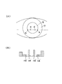
図19(A)は上記イメージセンサ14に投影される眼球像の概略図であり、図19(B)は上記イメージセンサ14の出力ラインからの信号の強度分布を示す図である。
【0021】
以下、上記の各図を用いて視線の検出方法について説明する。
【0022】
光源13bより放射された赤外光は使用者の眼球15の角膜16を照射する。このとき角膜16の表面で反射した赤外光の一部により形成される反射角膜像d(虚像)は受光レンズ12により集光され、イメージセンサ14上の位置d’に結像する。同様に光源13aにより放射された赤外光は、眼球15の角膜16を照射する。このとき、角膜16の表面で反射した赤外光の一部により形成された角膜反射像eは受光レンズ12により集光され、イメージセンサ14上の位置e’に結像する。
【0023】
また、虹彩17の端部a,bからの光束は、受光レンズ12を介してイメージセンサ14上の位置a’,b’に該端部a,bの像を結像する。受光レンズ12の光軸に対する眼球15の光軸の回転角θが小さい場合、虹彩17の端部a,bのx座標をxa,xbとすると、瞳孔19の中心位置cの座標xは、
xc≒(xa+xb)/2
と表される。
【0024】
また、角膜反射像d及びeの中点のx座標と角膜16の曲率中心oのx座標xoとは略一致する。このため角膜反射像の発生位置d,eのx座標をxd,xe、角膜16の曲率中心oと瞳孔19の中心cまでの標準的な距離をLocとし、距離Locに対する個人差を考慮する係数をA1とすると、眼球15の光軸15aの回転角θは、
A1×Loc×sinθ≒xc−(xd+xe)/2 …(1)
の関係式を略満足する。このため、図19(A)に示した様に、イメージセンサ14上に投影された眼球15の各特徴点(角膜反射像及び瞳孔の中心)の位置を検出することにより、眼球15の光軸15aの回転角θを求めることができる。
【0025】
眼球15の光軸15aの回転角は(1)式より、
β×A1×Loc×sinθ≒(xa′+xb′)/2
−(xd′+xe′)/2 …(2)
とかきかえられる。ただし、βは受光レンズ12に対する眼球15の位置により決まる倍率で、実質的には角膜反射像の間隔|xd′−xe′|の関数として求められる。
【0026】
眼球15の光軸の回転角θは
θ≒arcsin{(xc′−xf′)/(β×A1×Loc)}………(3)
と書き換えられる。ただし
xc′≒(xa′+xb′)/2
xf′≒(xd′+xe′)/2
である。
【0027】
ところで、使用者の眼球15の光軸15aと視軸とは一致しないため、使用者の眼球の光軸の水平方向の回転角θが算出されると、光軸と視軸との角度補正をすることにより使用者の水平方向の視線θHは求められる。眼球15の光軸15aと視軸との補正角度δに対する個人差を考慮する係数(視線補正係数)をB1とすると、使用者の水平方向の視線θHは
θH =θ±(B1×δ) ………(4)
と求められる。ここで符号±は、使用者に関して右への回転角を正とすると、観察装置(ファインダー系)をのぞく使用者の目が左目の場合は+、右目の場合は−の符号が選択される。
【0028】
又、同図においては、使用者の眼球がz−x平面(水平面)内で回転する例を示しているが、使用者の眼球がy−z平面(垂直面)内で回転する場合においても同様に検出可能である。ただし、使用者の視線の垂直方向の成分は眼球15の光軸15aの垂直方向の成分θ′と一致するため垂直方向の視線θVは
θV=θ′
となる。
【0029】
さらに、光学装置として一眼レフカメラを用いた場合においては視線データθH,θVより使用者が見ているピント板上の位置(xn,yn)は

ここで視線の個人差を補正する係数はA1、B1と二つであるため、例えば使用者に位置の異なる二つの視標を見てもらい、該指標の位置と上記(5)式に従い算出された固視点の位置とを一致させることにより、前記係数A1,B1を求めることが可能である。
【0030】
このようにして、撮影者が撮影画面のどこを見ているのかを検出する事により、検出された座標(xn,yn)に最も近い位置に存在する焦点検出点を、撮影レンズの焦点調節動作を行うための焦点検出点として決定できる。
【0031】
【発明が解決しようとする課題】
カメラが焦点検出点から得られる被写体空間情報をもとに、撮影レンズの焦点調節動作を行う焦点検出点を決定する従来方式の自動選択アルゴリズムにおいては、一連のグルーピング手法によって、全ての焦点検出点から一部の焦点検出点が抽出され、さらに撮影画面上の焦点検出点の相対位置によって対象とする焦点検出点は絞り込まれ、最終的に近点優先の原理によって一つの焦点検出点が選択されている。すなわち、撮影画面上に存在する焦点検出点は、各情報によって篩に掛けられ、それぞれの情報で1つでも条件を満足しない場合には、最終的に撮影レンズの焦点調節動作を行うための焦点検出点として選択されない仕組みになっている。
【0032】
このアルゴリズムでは、撮影画面上の焦点検出点が増えた場合を考えると、互いに近傍に存在する隣接した2つの焦点検出点においても、各条件を当てはめたとき、微妙な差異によってでも篩で分断されてしまうことが生じ、極端に異なる結果が得られることになる。
【0033】
従って、このような篩方式による焦点検出点の抽出方法は、特定の焦点検出点が選択されにくかったり、被写体やカメラの構え方のわずかな変化によって、大きく異なるピント結果が得られることになる。
【0034】
また自動選択アルゴリズムにおいては、本質的にカメラが撮影者の意図を予測している点からして、撮影シーンによっては撮影者の意図する焦点検出点とはずれが生じる事は避けられない。例えば図20のように、撮影画面上主被写体となる候補が2つ以上存在する場合、自動選択アルゴリズムによると手前の花にピントが合される。しかし実際には、撮影者は手前をぼかして奥の花を主被写体としてピントを合わせたかったのかもしれない。
【0035】
さらに、図21のようなシーンにおいて、手前の植木と中央付近の車では、自動選択アルゴリズムでは、近点優先の原理から手前の植木にピントを合わせることになる。撮影者が観察すれば主被写体になりにくいと容易に判断できる物体でも、自動選択アルゴリズムは、被写体情報であるデフォーカス量から一律に主被写体を予測するので、撮影者の意思情報がない以上、このような問題が必然的に残ってしまう。
【0036】
一方で撮影者の眼球像を観察する事により、視線方向を検出して撮影レンズの焦点調節動作を行う焦点検出点を決定する、視線選択アルゴリズムでは、算出される撮影画面上での座標が必ずしも撮影者が意図していた座標とは一致しないという問題がある。この原因は数多く確認されているが、代表的なものとして、眼球動作が無意識のうちに続けられていたり、周辺視野でもって外界を観察する事があることから、視線を捉えればその人が何を観察しているのかを必ず検出できるとは限らない点、睫や瞼が瞳孔に掛かったり、外乱光によって偶発的に生じる像の乱れによって取得眼球画像に不具合が生じる点、撮影ごとに変化するカメラの構え方による点、周辺照度変化による瞳孔径の変化や回転角の変化による点などが挙げられる。
【0037】
以上のように従来方式による自動選択アルゴリズム、視線選択アルゴリズム双方にそれぞれ問題があり、撮影者は思い通りの焦点検出点を選択することに必ずしも成功するとは限らなかったのである。
【0038】
(発明の目的)
本発明の目的は、複数の焦点検出点のうち特定の焦点検出点が選択されにくかったり、被写体やカメラの構え方のわずかな変化によって大きくピントがずれてしまうといったことを無くすことのできる自動焦点カメラを提供しようとするものである。
【0039】
【課題を解決するための手段】
上記目的を達成するために、本発明は、撮影画面上の複数の焦点検出点のうちの1つの焦点検出点を選択し、該焦点検出点にて得られる焦点検出情報によって撮影レンズの焦点調節動作を行う合焦手段を有する自動焦点カメラにおいて、焦点検出点ごとにデフォーカス量を検出する第1の検出手段と、姿勢を検出する第2の検出手段と、前記第1の検出手段によって検出された複数の焦点検出点に対応するデフォーカス量から最も近い1の焦点検出点および当該1の焦点検出点に離散していて且つ無限遠側のデフォーカス量を示す焦点検出点の点数を当該1の焦点検出点に離散していなく且つ無限遠側のデフォーカス量を示す焦点検出点の点数よりも高い点数を付与するとともに、前記第2の検出手段によって検出された姿勢に基づいて予め定められた点数化マップに従って前記複数の焦点検出点の各々に対して点数を付与する点数化手段とを有し、前記合焦手段は、前記点数化手段により、付与された前記複数の焦点検出点の点数をそれぞれの焦点検出点毎に合計した数値の多寡により、前記複数の焦点検出点のうちの1つの焦点検出点を選択して撮影レンズの焦点調節動作を行う自動焦点カメラとするものである。
【0040】
【発明の実施の形態】
以下、本発明を図示の実施の形態に基づいて詳細に説明する。
【0041】
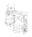
図1は本発明を一眼レフカメラに適用したときの実施の一形態を示す要部概略図である。
【0042】
図1において、1は撮影レンズで、便宜上2枚のレンズで示したが、実際はさらに多数のレンズから構成されている。2は主ミラーで、ファインダ系による被写体像の観察状態と被写体像の撮影状態に応じて撮影光路へ斜設され或は退去される。3はサブミラーで、主ミラー2を透過した光束をカメラボディの下方の後述する焦点検出装置6へ向けて反射する。4はシャッタ、5は感光部材で、銀塩フィルム或はCCDやMOS型等の固体撮像素子等である。6は焦点検出装置であり、結像面近傍に配置されたフィールドレンズ6a,反射ミラー6b及び6c,二次結像レンズ6d,絞り6e、複数のCCDから成るラインセンサ6f等から構成されている。
【0043】
この実施の形態における焦点検出装置6は、周知の位相差方式にて焦点検出を行うものであり、図3に示すように、撮影画面内(ファインダ視野内)の複数の領域である200〜206(7箇所)を焦点検出点として、該焦点検出点が焦点検出可能となるように構成されている。
7は撮影レンズ1の予定結像面に配置されたピント板、8はファインダ光路変更用のペンタプリズム、9,10は各々観察画面内の被写体輝度を測定するための結像レンズと測光センサである。結像レンズ9はペンタプリズム8内の反射光路を介してピント板7と測光センサ10を共役に関係付けている。
【0044】
上記ペンタプリズム8の射出後方には光分割器11aを備えた接眼レンズ11が配置され、使用者の眼15によるピント板7の観察に使用される。光分割器11aは、例えば可視光を透過し赤外光を反射するダイクロイックミラーより成っている。12は受光レンズ、14はCCD等の光電変換素子列を二次元的に配したイメージセンサで、受光レンズ12に関して所定の位置にある使用者の眼球15の瞳孔近傍と共役になるように配置されている。13a〜13fは各々照明光源であるところの赤外発光ダイオードである。
【0045】
21は明るい被写体の中でも視認できる高輝度のスーパーインポーズ用LEDで、ここから発光された光は投光用プリズム22を介し、主ミラー2で反射されてピント板7の表示部に設けた微小プリズムアレイ7aで垂直方向に曲げられ、ペンタプリズム8,接眼レンズ11を通って使用者の眼15に達する。
【0046】
そこで、ピント板7の焦点検出点に対応する複数の位置にこの微小プリズムアレイ7aを枠状に形成し、これを各々に対応した7つのスーパーインポーズ用LED21(各々をLED−L1,LED−L2,LED−C,LED−R1,LED−R2,LED−U,LED−Dとする)によって照明する。これによって前述のように、図3に示したファインダ視野において、各々の焦点検出点200,201,202,203,204,205,206がファインダー視野内で光り、焦点検出点を表示させることができるものである。23はファインダ視野領域を形成する視野マスク、24はファインダ視野外に撮影情報を表示するためのファインダ内LCDで、照明用LED(F−LED)25によって照明される。上記ファインダ内LCD24を透過した光は三角プリズム26によってファインダ視野外に導かれ、図3に示した様に使用者に各種の撮影情報を視認させることができる。
【0047】
27はカメラの姿勢を検出するための公知の姿勢センサであり、この出力によりカメラが縦位置に構えられているのか、横位置に構えられているのかといった情報を検出する。
【0048】
31は撮影レンズ1内に設けた絞り、32は後述する絞り駆動回路111を含む絞り駆動装置、33はレンズ駆動用モータ、34は駆動ギヤ等から成るレンズ駆動部材である。35はフォトカプラで、前記レンズ駆動部材34に連動するパルス板36の回転を検知して焦点調節回路110に伝えている。焦点調節回路110は、この情報とカメラ側からのレンズ駆動量の情報に基づいて前記レンズ駆動用モータ33を所定量駆動させ、撮影レンズ1を合焦位置に移動させるようになっている。37は公知のカメラとレンズとのインターフェイスとなるマウント接点である。
【0049】
図2(A),(B)は、上記の構成より成る一眼レフカメラの上面と背面の概略図である。図2において、41はレリーズ釦であり、42は外部モニタ表示装置としてのモニタ用LCDである。44は撮影モード等の選択を行うためのモードダイヤルである。
【0050】
45は他の操作部材及びモードと組み合わせることによって、種々の設定値を設定するための回転式電子ダイヤルである。46は、本発明の特徴と直接かかわる、画面内の複数の焦点検出点200〜206のいずれかを用いて、焦点検出を行うかを選択する焦点検出点選択釦である。この動作については後で詳細に説明する。また、他の図2に記載されている操作部材は本発明と特に関係しない為、説明を省略する。
【0051】
図4は上記構成の一眼レフカメラに内蔵された電気回路図であり、図1と同じ部分は同一符号を付してある。
【0052】
カメラ本体に内蔵されたマイクロコンピュータ(以下、CPUと記す)100には、視線検出回路101、測光回路102、自動焦点検出回路103、信号入力回路104、LCD駆動回路105、LED駆動回路106、IRED駆動回路107、シャッタ制御回路108、モータ制御回路109が接続されている。また、撮影レンズ1内に配置された焦点調節回路110、絞り駆動回路111とは、図1で示したマウント接点37を介して信号の伝達がなされる。
【0053】
CPU100に付随したEEPROM100aは記憶手段としての視線の個人差を補正する視線補正データの記憶機能を有している。前記視線検出回路101は、イメージセンサ14(CCD−EYE)からの眼球像の信号をA/D変換し、この像情報をCPU100に送信する。CPU100は後述するように視線検出に必要な眼球像の各特徴点を所定のアルゴリズムにしたがって抽出し、さらに各特徴点の位置から使用者の視線を算出する。
【0054】
ラインセンサ6fは、前述の図3に示すファインダ視野内の7つの焦点検出点200〜206に対応した7組のラインセンサCCD−L2,CCD−L1,CCD−C,CCD−R1,CCD−R2,CCD−U,CCD−Dから構成される公知のCCDラインセンサである。前記自動焦点検出回路103は、上記のラインセンサ6fから得た電圧をA/D変換し、CPU100に送る。
【0055】
SW1はレリーズ釦41の第1ストロークでオンし、測光,AF,視線検出動作等を開始させる為のスイッチ、SW2はレリーズ釦の第2ストロークでオンするレリーズスイッチ、SW−AELは43のAEロック釦を押すことによってオンするAEロックスイッチ、SW−DIAL1とSW−DIAL2は、45の電子ダイアル内に設けられたダイアルスイッチで、信号入力回路104のアップダウンカウンタに入力され、この電子ダイアルの回転クリック量がここでカウントされる。
【0056】
前記LCD駆動回路105は、ファインダ内LCD24やモニタ用LCD42を表示駆動させるための公知の構成より成るもので、CPU100からの信号に従い、絞り値,シャッタ秒時,設定した撮影モード等の表示をモニタ用LCD42とファインダ内LCD24の両方に同時に表示させることができる。
【0057】
前記LED駆動回路106は、照明用LED(F−LED)25とスーパーインポーズ用LED21を点灯,点滅制御する。前記IRED駆動回路107は、赤外発光ダイオード(IRED1〜6)13a〜13fを状況に応じて選択的に点灯させる。
【0058】
前記シャッタ制御回路108は、通電すると先幕を走行させるマグネットMG−1と、後幕を走行させるマグネットMG−2を制御し、感光部材に所定光量を露光させる。前記モータ制御回路109は、フィルムの巻き上げ、巻き戻しを行うモータM1と主ミラー2及びシャッタ4のチャージを行うモータM2を制御するためのものである。
【0059】
これらのシャッタ制御回路108、モータ制御回路109によって一連のカメラのレリーズシーケンスが動作する。
【0060】
次に、本実施の形態における複数の焦点検出点から実際に撮影レンズの焦点調節動作を行うために用いられる焦点検出点を選択する方法について説明する。
【0061】
図5(A)〜(H)は、焦点検出点選択釦46を押下ながら電子ダイヤル45を時計方向にクリック回転させるごとに(A)→(B)→…→(H)とファインダ内のスーパーインポーズ表示が順次変化し、さらにもう1クリック回転させることで(A)に戻る様子を示している。また、反時計方向に電子ダイヤル45を回転させたときには、図5の矢印とは正反対の順に表示を行う。
【0062】
図5(A)の表示状態において、他の操作部材の操作に移行すると、カメラが7つの焦点検出点200〜206より撮影レンズの焦点調節動作を行うための焦点検出点を、各焦点検出点のデフォーカス量の状態、および焦点検出点の相対位置、および撮影者の視線方向をそれぞれ考慮して選択する焦点検出点融合選択モードに設定される。この融合選択モードにおける融合選択アルゴリズムが本実施の形態の中心となるので、後に詳細に説明する。
【0063】
図5(B)〜(H)は7つの焦点検出点から撮影レンズの焦点調節動作を行うための焦点検出点を、撮影者が予めある1つの焦点検出点に限定しておくための、焦点検出点手動選択モードにおける表示状態を表す。例えば図5(B)は焦点検出点200に限定したものであり、図5(C)は焦点検出点201に限定したものである。
【0064】
この焦点検出点手動選択モードによる焦点検出点選択は、焦点検出点を1点に絞っているために焦点検出時間が短くなり、合焦スピードのアップが図れると同時に、被写体がファインダ視野に対して一定の位置関係に固定されている場合においては、撮影者の意図する主被写体に正確にピント合わせを行うことができるといった効果がある。
【0065】
逆に焦点検出点が1点しか存在しないために、被写体が動いたり、構図を少し変えただけで主被写体を焦点検出点から外してしまい、焦点検出が不可能となる欠点がある。さらに手動にて焦点検出点を切換えるのは手間がかかり、シャッタチャンスを逃す恐れもある。
【0066】
そこで、撮影シーンと撮影者の意思に応じて、7つの焦点検出点から任意の1つをカメラが自動的に選択する、焦点検出点融合選択モードが有効となる。
【0067】
図6は、図5(A)の表示状態において撮影を行う焦点検出点融合選択モードに設定された場合の、融合選択アルゴリズムのフローチャートを示す。ここでの融合選択アルゴリズムは、撮影モードにおいて撮影者が被写体に対してカメラを構え、レリーズ釦41の第1ストロークによってONされるスイッチSW−1をONしたときに開始される。
【0068】
スイッチSW−1がONされると、7つのラインセンサによって焦点検出が行われる(S100)。このときそれぞれの焦点検出点に対応した被写体空間領域のデフォーカス量が検出される。ステップS101に移行し、このデフォーカス量を基準に被写体空間情報の点数化が行われる。
【0069】
被写体空間情報の点数化とは、
【0070】
【数式1】
で表されるように、デフォーカス量を基準に各焦点検出点に数値を割り振ることである。具体的には、図7の被写体空間情報の点数化動作を示すサブルーチンを用いて説明する。
【0072】
図7のサブルーチンである被写体空間情報の点数化に移行(S101)すると、まずデフォーカス量を基準に被写体のグループ化を試みるサブルーチンS102へ進む。図8は焦点検出ラインによるグループ化を示すサブルーチンである。ステップS111において焦点検出に成功したライン数がカウントされ、焦点検出成功ラインが1ラインのみで、残り6ラインで出力エラーとなった場合、撮影レンズの焦点調節動作を行うための焦点検出点は、このラインに対応した焦点検出点に決定される(S112)。この場合、カメラはこの焦点検出点でしかピント合せができないので、被写体空間情報のみによって、この焦点検出点が選択されることになる。
【0073】
複数のラインで焦点検出に成功した場合、ステップS113に移行する。この複数の焦点検出成功ラインの中で、検出されたデフォーカス量から、カメラから被写体の距離が最も近いと判断された検出ラインをラインAと名付ける。次にステップS114において、ラインAからカメラに対して無限遠側の中デフォーカス範囲内に焦点検出成功ラインが存在するか確認する。中デフォーカス範囲とは、予定結像面5の近傍において、光軸方向にピントのずれ量換算でA(mm)のデフォーカス量を表す。
【0074】
すなわち、撮影レンズの焦点距離をf(mm)、予定結像面5からカメラに最も近い被写体までの距離をL(mm)とすると、カメラに最も近い被写体から無限遠側に略{(L−f)2/f2 }×A(mm)の範囲内に存在する被写体のグルーピングを目的とする。この中デフォーカス範囲内に焦点検出成功ラインが存在すれば、ステップS115に移り、存在するこれら全てのラインをラインBと名付ける。次にステップS116に移行し、カメラから最も遠い被写体を捉えたラインBからさらに、小デフォーカス範囲内に焦点検出ラインが存在するか確認する。このときの小デフォーカス範囲とは、予定結像面5の近傍において、光軸方向にピントのずれ量換算でB(mm)のデフォーカス量を表す。ただし、A>Bである。小デフォーカス範囲内に焦点検出成功ラインが存在すれば、それらをラインCと名付ける。
【0075】
すなわち、カメラから最も近い被写体に対し、中デフォーカス範囲内に被写体が存在する場合には、グルーピングの範囲をもう少し広げることを意図する。ラインCが存在した場合には、ステップS118のおいて、ラインA,ラインB、ラインCを主被写体グループとする。ステップS116で、小デフォーカス範囲内に焦点検出ラインが存在しなかった場合、すなわちラインCが存在しない場合には、ステップS119において、ラインA,ラインBを主被写体グループとする。ステップS114において、中デフォーカス範囲内に焦点検出成功ラインが存在しない場合には、ステップS120において、ラインAをラインOと名前を付け直し、2番目にカメラから近い被写体を捉えた焦点検出成功ラインをラインAとする。
【0076】
次に、ステップS121に移行し、ステップS114と同様に、ラインAからカメラに対して無限遠側に中デフォーカス範囲内に焦点検出成功ラインが存在するか確認する。存在すればそれらのラインを全てラインBと名付け(S122)、ステップS123に移り、ステップS116と同様にカメラから最も遠い被写体を捉えたラインBからさらに、小デフォーカス範囲内に焦点検出ラインが存在するか確認する。存在すればステップS124で、それら全てのラインをラインCと名付ける。この場合、ラインO,ラインA,ラインB,ラインCを主被写体グループとする。
【0077】
上記ステップS123で、小デフォーカス範囲内に焦点検出成功ラインが存在しない場合には、ラインO,ラインA,ラインBを主被写体グループとする。また、上記ステップS121で、中デフォーカス範囲内に焦点検出成功ラインが存在しない場合には、ラインO,ラインAを主被写体グループとする。
【0078】
以上のように、カメラから最も近い被写体を基準に主被写体グループを定義する。
【0079】
このようにして主被写体グループが定義されると、図7のステップS103に移行し、ラインO、A、B,Cに対して特定の点数が与えられる。このときの点数化ルールを示すのが図9である。
【0080】
本実施の形態においては、得られる各情報に関して、主被写体が存在するであろう焦点検出点には高得点を、そうでない焦点検出点には低得点を与えることにした。さらに、割り振る点数の範囲は任意に設定可能であるが、本実施の形態では、1点〜5点を各焦点検出点に割り振ることにした。
【0081】
図9の点数化ルールでは、まずデフォーカス量検出によって被写体グループを捉えたラインに、ラインO,A,B,Cのいずれが存在するかによって分類している。さらにグループに存在するラインO,A,B,Cを捉えた焦点検出点の撮影画面上での配列が、互いに隣り合うか、もしくは離れた位置に存在するかによって分類している。こうして分類されたラインO,A,B,Cに点数が与えられる。ただし、ラインO,Aは図8のフローチャートによると、それぞれ1本もしくは0本しか存在しないが、ラインB,Cはグループ化によっては複数存在し得るので、とくに隣接および離散のいずれの可能性もあり、主被写体の構成に影響の大きい、複数のラインBが存在する場合の為に#Bを設けた。
【0082】
一例を図10を用いて説明する。
【0083】
焦点検出点が不可能であった焦点検出点205は対象から外し、残りの焦点検出点に点数を割り振る。焦点検出点203がラインAとなったとすると、まずこの焦点検出点に点数5がつく。ラインBは焦点検出点200と204に名付けられた。このとき焦点検出点203に隣り合う焦点検出点204には点数4が与えられるが、これらと離れた焦点検出点200には点数5が与えられる。ラインCと名付けられた焦点検出点206には点数4が与えられる。その他の焦点検出は可能であったが遠距離に存在する被写体を捉えた焦点検出点201,202には点数1が付けられる。このようにして、ラインに付けられた点数をステップS104で実際の全ての焦点検出点に被写体空間情報として対応させることができる。ちなみにこの場合には、
【0084】
【数式2】
となる。
【0086】
このようにして被写体空間情報を点数化した後、図7のステップS104を介して図6のメインルーチンへ戻り、ステップS200へ進む。
【0087】
図6のステップS200では、本体に具備された姿勢センサ27によってカメラの姿勢を検出する。これにより、撮影者がカメラを横位置に構えているのか縦位置に構えているのか、さらに縦位置であれば、カメラグリップ40を天方向に向けた構え方なのか、もしくは地方向に向けた構え方なのかを検出できる。これら3つのタイプの構え方を、図11(A),(B),(C)の各状態とする。
【0088】
カメラの姿勢検出が終わると、ステップS201へ移行し、焦点検出点情報の点数化が行われる。焦点検出点情報とは、カメラの構え方による撮影画面上の焦点検出点の相対的な配置状態と、それに対応する一般的な傾向としての、主被写体出現頻度を表す。すなわち、撮影画面に対し中央寄りもしくは上方に主被写体を置く構図が一般的に多いことを考慮したものであり、撮影画面中央寄りもしくは上方の焦点検出点を選ばれやすいように点数操作を行うものである。一方で、従来の篩方式にこの考えを適用したときに生じる、特定の焦点検出点が極端に選ばれにくいといった弊害を取り除くための操作でもある。
【0089】
この焦点検出点情報の点数化とは、具体的には、
【0090】
【数式3】
で表すこととし、カメラの状態図11の(A),(B),(C)それぞれに図12で示す点数マップに従い、
【0092】
【数式4】
と本実施の形態では定めることにする。
【0094】
次に、ステップS300に進み、撮影者の視線検出を行う。視線検出原理は従来例に示した通りであるので、ここでは省略する。
【0095】
視線検出によって撮影者が撮影画面上どの点を観察しているのか、多少の誤差は含むものの、おおよその座標(Xn,Yn)が検出される。おおよその座標(Xn,Yn)が検出されると、ステップS301に移行し、視線情報の点数化を行う。
【0096】
視線情報の点数化とは、
【0097】
【数式5】
で表されるように、視線座標を基準に各焦点検出点に数値を割り振ることである。具体的には図13の視線情報の点数化動作を示すサブルーチンを用いて説明する。
【0099】
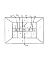
ステップS301でサブルーチンである視線情報の点数化に入ると、ステップS311に移行し、視線座標の撮影画面エリアへの対応付けが行われる。撮影画面エリアとは、図14のように、撮影画面を19の領域に分割した各エリアa〜sであると本実施の形態では定義する。検出された視線座標(Xn,Yn)がどのエリアに属するかによって、7つの焦点検出点に与えられる点数を変化させることを目的とする。従ってステップS311では、具体的には、視線座標→撮影画面エリアの変換が行われる。
【0100】
次に、撮影画面エリア→各焦点検出点への点数割り振りをステップS312で行う。本実施の形態では、図15に示す点数化ルールを適用する。これは、図14の各エリアa〜sに対し、検出視線座標がその領域に属したとき、カメラは7つの焦点検出点のうち、どの焦点検出点で撮影レンズの焦点調節動作を行うのが妥当であるのかを基準に、高い点数から順に低い点数までを割り振ったものである。例えば、エリアaに視線座標(Xn,Yn)が検出されると、エリアaが対象とする焦点検出点はエリアaに最も近い焦点検出点204のみであり、この焦点検出点に点数5が与えられ、その他の焦点検出点には点数1が与えられる。
【0101】
また、エリアoに検出されると、エリアoに含まれる焦点検出点205にもっとも高い点数5が与えられ、焦点検出点205に隣接する焦点検出点202に点数4が、次に近い焦点検出点201,203に点数3が与えられ、エリアoの対象外である焦点検出点200,204,206には点数1が与えられる。これは、検出視線座標には誤差が含まれていることを前提としているため、たとえエリア内に焦点検出点が存在していても、その点のみを対象とはせず、少し広い範囲での焦点検出点の全てを対象として、最終的に撮影レンズの焦点調節動作を行うための焦点検出点として選択される可能性を持たせておくためである。
【0102】
以上の操作により視線情報の点数化が終わると、図6のメインルーチンに戻り、ステップS400の情報の融合/比較演算に移行する。ここでは、これまでのルーチンにより数値化された被写体空間情報および焦点検出点情報および視線情報を融合し、7つの焦点検出点の間で比較を行う。
【0103】
各焦点検出点の合計得点を、
【0104】
【数式6】
で計算することにする。
【0106】
本実施の形態では、di ,pi ,ei の全ての点数化に対し点数0から5の範囲で与えている。すなわちどの情報も均等に取り扱っていることになる。そこで各情報間の重み付け係数として、α, β, γを用意する。これはどの情報を重視するかによって自由に設定可能な係数である。例えば、視線情報を補助情報として、被写体空間情報や焦点検出点情報を主たる情報として取り扱うならば、γを小さくしてα,βを大きくすれば良いし、逆に視線情報を重視するならばγを大きくすれば良い。
【0107】
このように重み付け係数を介して合計された各焦点検出点の合計得点を比較する。本実施の形態では、主被写体が存在するであろう焦点検出点には高得点を、そうでない焦点検出点には低い得点を与え、さらに重視する情報には重み付け係数で高い比率を与えてきたので、最終的にどの焦点検出点で撮影レンズの焦点調節動作を行うかは、合計得点の最も高い焦点検出点を選択すれば良い(ステップS500)。
【0108】
以上のプロセスにより、最終的に撮影レンズの焦点調節動作を行うための焦点検出点が1つ選択された。1つの焦点検出点が選択されると、その焦点検出点をスーパーインポーズ表示で撮影者に知らしめ、公知の撮影動作が実行される。
【0109】
以上の実施の形態によれば、カメラに具備されるセンサ群(ラインセンサ群6f、イメージセンサ14、姿勢センサ27)から得られる各種の情報を、焦点検出点を基準として数値化し、最終的に合計して得られる数値の多寡により、撮影レンズの焦点調節動作を行うための焦点検出点を選択する方式であるため、複数存在する焦点検出点のうち特定の焦点検出点が選択されにくかったり、被写体やカメラの構え方のわずかな変化によって大きく異なるピント結果になってしまうといった課題が解決される。
【0110】
具体的には、複数の焦点検出点によって検出されるデフォーカス量や被写体までの距離による被写体空間情報、およびカメラの構え方による、主被写体出現の頻度を表す焦点検出点情報、および撮影者が撮影画面上の注視座標を略表す視線情報のうち、少なくとも2つを用いることとしている。また、各情報間の足し合わせを行う際に、どの情報カテゴリーを優先するかによって、足し合わせの比率を変化させるようにしている。又、焦点検出点で捉えた、カメラに最も近接する被写体から一定距離に存在する被写体を被写体グループとし、このグループを捉えた焦点検出点に対して、近接する被写体を捉えた焦点検出点から順に点数を付与したり、前記被写体グループ内に、空間的に離れた被写体が存在すると思われる場合には、主被写体である可能性を同等とする点数を付与するようにしている。又、撮影画面を複数の領域に分割し、視線座標がある領域に計算された場合、どの焦点検出点において撮影レンズの焦点調節動作をさせるのが妥当かを基準に、全ての焦点検出点に対して点数を付与した点数化マップを用意している。
【0111】
また、従来の自動選択アルゴリズムでは、撮影者の意思を情報として取り込んでいなかったため、思いもよらない被写体にピントが合わせられたり、一方で、撮影者の視線によって焦点検出点を選択する視線選択方式では、種々の理由から正確な撮影画面上の視線座標は検出できないために、必ずしも撮影者が意図していた座標と一致しなかったりしていた。しかし本実施の形態によれば、特定の情報に偏ることなく、各情報の数値化操作によって、互いの情報の不足する部分を補い、総合的に主被写体の存在する可能性が最も高い焦点検出点を選択するため、従来のアルゴリズムでは成し得なかった主被写体の捕捉率を実現することが可能となった。
【0112】
(変形例)
情報のカテゴリーとして、上記の実施の形態では、被写体空間情報および焦点検出点情報および視線情報の3つを対象としたが、最終的に撮影レンズの焦点調節動作を行うための焦点検出点を選択するための情報としては、このうち任意の2つのみを用いても良い。
【0113】
また同様に、対象とする情報のカテゴリーは、この3つに絞られるものではなく、焦点検出点を選択するために有意な情報であれば、カテゴリーの対象としても良い。
【0114】
また、焦点検出点を7つとしたが、この点数に限るものではない。
【0115】
また、情報の点数化の設定点数範囲を0〜5の整数値を用いたが、この範囲は任意の実数値を設定しても良い。また、被写体が存在すると思われる焦点検出点ほど高得点を与えたが、逆にそのような焦点検出点に低い点数を与え、最終的に最も低い得点が付与された焦点検出点を選択されるようにしてもよい。
【0116】
本実施の形態で用いた各情報の点数化マップは、実情に即して任意に変更可能である。
【0117】
また、視線情報における撮影画面の領域分割数を19とし、図14のように設定したが、この境界の分割ラインと領域分割数は自由に設定可能である。
【0118】
また、本実施の形態での点数化の順序は、被写体空間情報→焦点検出点情報→視線情報の順であったが、この順序は任意に設定可能である。
【0119】
【発明の効果】
以上説明したように、本発明によれば、複数の焦点検出点のうち特定の焦点検出点が選択されにくかったり、被写体やカメラの構え方のわずかな変化によって大きくピントがずれてしまうといったことを無くすことができる自動焦点カメラを提供できるものである。
【図面の簡単な説明】
【図1】本発明の実施の一形態に係る一眼レフカメラの要部概略図である。
【図2】図1の一眼レフカメラの要部外観図である。
【図3】図1のファインダ視野図である。
【図4】図1の一眼レフカメラの電気的構成を示すブロック図である。
【図5】図3のファインダ視野内の表示状態を説明する為の図である。
【図6】本発明の実施の一形態における動作を示すフローチャートである。
【図7】図6内のサブルーチンを示すフローチャートである。
【図8】同じく図6内のサブルーチンを示すフローチャートである。
【図9】本発明の実施の一形態における点数化マップ図である。
【図10】本発明の実施の一形態における点数化例を示す図である。
【図11】一般的なカメラの構え方について説明する為の図である。
【図12】本発明の実施の一形態における点数化マップ図である。
【図13】図6内のサブルーチンを示すフローチャートである。
【図14】本発明の実施の一形態における撮影画面分割を示す図である。
【図15】本発明の実施の一形態における点数化マップ図である。
【図16】従来例のファンダ視野図である。
【図17】従来例の自動選択アルゴリズムを示すフローチャートである。
【図18】一般的な視線検出装置の要部概略図である。
【図19】眼球像の要部概略図である。
【図20】撮影シーンの一例を示す図である。
【図21】同じく査定シーンの他の例を示す図である。
【符号の説明】
1 撮影レンズ
6 焦点検出装置
6f ラインセンサ群
13 赤外発光ダイオード(IRED)
14 イメージセンサ(CCD−EYE)
24 ファインダ内LCD
27 姿勢センサ
41 レリーズ釦
46 焦点検出点選択釦
100 CPU
101 視線検出回路
103 焦点検出回路
110 焦点調節回路
200〜206 焦点検出点[0001]
BACKGROUND OF THE INVENTION
The present invention relates to an improvement of an autofocus camera having a plurality of focus detection points on a photographing screen.
[0002]
[Prior art]
As one type of focus detection device, the exit pupil of the photographing lens is divided by the optical system of the focus detection system, and two subject images formed by the light flux that has passed through each pupil region are received by the photoelectric conversion element array. A method for detecting the focus state of a photographic lens by detecting the amount of displacement (displacement) of the relative positions of two subject images is widely known. In this way, the relative position displacement is obtained, and the defocus amount of the photographing lens, so-called defocus amount, is detected. When the detection method for detecting the defocus amount is used, the pair of sensors extract only the luminance distribution of a specific area in the subject space, and therefore the defocus amount is calculated for a subject that does not have the luminance distribution in that area. I can't. Therefore, a method that enables focus detection for a larger number of subjects by preparing multiple sensor pairs and corresponding focus optical systems and extracting the luminance distribution of the multiple subject areas has been disclosed. 59-28886, JP-A-62-212611 and the like.
[0003]
The camera grasps the state of the subject space, that is, the relative position of the subject existing in the space corresponding to the focus detection point, based on the defocus amount detected from the plurality of focus detection points (meaning a region where focus detection is performed). I can do things. The plurality of focus detection points for performing focus detection are, for example, 200 to 206 in FIG. 16 (actually, focus detection point marks are shown. As A method for obtaining a final defocus amount from a plurality of focus detection mechanisms corresponding to the plurality of focus detection points, that is, a focus adjustment operation of the photographing lens. As a method for determining a focus detection point for performing the focusing, a near point priority method in which the central focus detection point is weighted, and a grouping method in which subjects whose relative positions are close to each other are grouped are known. .
[0004]
An example is shown based on the focus detection point automatic selection algorithm of Japanese Patent Application No. 11-062551, which is a proposal by the present applicant.
[0005]
FIG. 17 is a flowchart of an automatic focus detection point selection algorithm that employs the near point priority and grouping method. The line in the figure indicates a line sensor composed of a photoelectric conversion element array corresponding to each focus detection point. Since the actual detection is performed by the output of the line sensor, description will be made with reference to seven lines corresponding to the
[0006]
When automatic focus detection point selection is started, focus detection is performed by the seven line sensors. At this time, the luminance distribution of the area is extracted from the subject corresponding to each focus detection point. If there is no luminance distribution in the subject area, the line output becomes an error.
[0007]
First, in step S01, when the luminance distribution is successfully extracted, that is, the number of lines for which focus detection is successful is counted, and there is only one focus detection success line and an output error occurs in the remaining six lines, the focus of the photographing lens A focus detection point for performing the adjustment operation is determined as a focus detection point corresponding to this line (S02).
[0008]
If focus detection is successful for a plurality of lines, the process proceeds to step S03. Among the plurality of focus detection success lines, a detection line that is determined to be the closest to the subject from the camera based on the detected defocus amount is named line A. Next, in step S04, it is confirmed whether a focus detection success line exists in the middle defocus range from the line A to the camera at infinity. The middle defocus range represents a defocus amount of a (mm) in the optical axis direction in the vicinity of the planned imaging plane.
[0009]
That is, if the focal length of the photographic lens is f (mm) and the distance from the planned imaging plane to the subject closest to the camera is L (mm), the object closest to the camera is approximately {(L−f ) 2 / F 2 } The purpose is to group subjects existing within a range of xa (mm). If a = 2 (mm), for example, when a photographic lens with a focal length of 50 (mm) is attached, and the subject closest to the camera is located 2.55 (m) from the image plane, The subject grouping is performed in the range of 5 (m) from the position to infinity.
[0010]
If a focus detection success line exists in the defocus range, the process moves to step S05, and all these existing lines are named line B. Next, the process proceeds to step S06, where it is confirmed whether a focus detection line exists within the small defocus range from the line B that captures the subject farthest from the camera. The small defocus range at this time represents a defocus amount of b (mm) in the optical axis direction in the vicinity of the planned imaging plane. However, a> b. If there are focus detection success lines in the small defocus range, they are named line C.
[0011]
That is, when the subject is within the middle defocus range with respect to the subject closest to the camera, the grouping range is intended to be expanded a little more. If line C exists, in step S08, line A, line B, and line C are set as the main subject group. If no focus detection line exists in the small defocus range in step S06, that is, if no line C exists, line A and line B are set as main subject groups in step S09.
[0012]
In step S04, if there is no focus detection success line in the middle defocus range, in step S10, the line A is renamed as line O, and the focus detection succeeds in capturing the subject closest to the camera. Let line A be line A.
[0013]
Next, the process proceeds to step S11, and as in step S04, it is confirmed whether a focus detection success line exists in the middle defocus range from the line A to the infinity side with respect to the camera. If they exist, all those lines are named line B (S12), and the process proceeds to step S13. As in step S06, there is a focus detection line within the small defocus range from line B that captures the subject farthest from the camera. Confirm whether to do. If it exists, all these lines are named line C in step S14. In this case, line O, line A, line B, and line C are set as the main subject group. If the focus detection success line does not exist within the small defocus range in step S13, line O, line A, and line B are set as the main subject group. In step S11, when there is no focus detection success line in the middle defocus range, the lines O and A are set as the main subject group.
[0014]
As described above, the main subject group is defined based on the subject closest to the camera.
[0015]
A line corresponding to the focus detection point close to the center detection point is extracted from the main subject group defined in this manner (S18). If there is one line extracted at this time (S21), that line is selected. If there are two or more lines, the line that detects the object closest to the camera is selected, and the focus detection corresponding to the selected line is detected. It is determined that the focus adjustment operation of the taking lens is performed at the point.
[0016]
With the above algorithm, a focus detection point where the main subject is supposed to exist is extracted from a plurality of focus detection points, and the focus adjustment operation of the photographing lens is performed at the focus detection point.
[0017]
On the other hand, cameras with a line-of-sight detection function for detecting which direction on the shooting screen the photographer is gazing at are widely provided. In Japanese Patent Laid-Open No. 2-264632, eye gaze detection is performed to irradiate a photographer's eyeball with infrared light, and to use the cornea reflection image by the reflected light from the cornea of the eyeball and the imaging position of the pupil. An apparatus is disclosed.
[0018]
FIG. 18 is a diagram illustrating the principle of a known gaze detection method.
[0019]
In the figure,
[0020]
FIG. 19A is a schematic diagram of an eyeball image projected on the
[0021]
Hereinafter, the gaze detection method will be described with reference to each of the above-described drawings.
[0022]
The infrared light emitted from the
[0023]
Further, the light beams from the ends a and b of the
xc≈ (xa + xb) / 2
It is expressed.
[0024]
Further, the x coordinate of the midpoint of the cornea reflection images d and e and the x coordinate xo of the center of curvature o of the
A1 × Loc × sin θ≈xc− (xd + xe) / 2 (1)
Is substantially satisfied. For this reason, as shown in FIG. 19A, the optical axis of the
[0025]
The rotation angle of the
β × A1 × Loc × sin θ≈ (xa ′ + xb ′) / 2
− (Xd ′ + xe ′) / 2 (2)
It can be rewritten. However, β is a magnification determined by the position of the
[0026]
The rotation angle θ of the optical axis of the
θ≈arcsin {(xc′−xf ′) / (β × A1 × Loc)} (3)
It can be rewritten as However,
xc′≈ (xa ′ + xb ′) / 2
xf′≈ (xd ′ + xe ′) / 2
It is.
[0027]
By the way, since the
θH = θ ± (B1 × δ) (4)
Is required. Here, when the rotation angle to the right with respect to the user is positive, the sign ± is selected when the user's eyes except the observation apparatus (finder system) are left eyes, and when the right eye is −, signs are selected.
[0028]
Further, in the figure, an example in which the user's eyeball rotates in the zx plane (horizontal plane) is shown, but even when the user's eyeball rotates in the yz plane (vertical plane). Similarly, it can be detected. However, since the vertical component of the user's line of sight coincides with the vertical component θ ′ of the
θV = θ ′
It becomes.
[0029]
Further, when a single-lens reflex camera is used as the optical device, the position (xn, yn) on the focusing screen that the user is viewing from the line-of-sight data θH, θV is
Here, there are two coefficients A1 and B1 for correcting the individual differences in the line of sight. For example, the user sees two targets at different positions, and is calculated according to the position of the index and the above equation (5). The coefficients A1 and B1 can be obtained by matching the positions of the fixed viewpoints.
[0030]
In this way, by detecting where the photographer is looking at the photographing screen, the focus detection point present at the position closest to the detected coordinates (xn, yn) is used to adjust the focus of the photographing lens. It can be determined as a focus detection point for performing.
[0031]
[Problems to be solved by the invention]
In the conventional automatic selection algorithm that determines the focus detection point for the focus adjustment operation of the photographic lens based on the subject space information obtained from the focus detection point, all focus detection points are obtained by a series of grouping methods. A part of the focus detection points are extracted, and the target focus detection points are narrowed down by the relative position of the focus detection points on the shooting screen, and finally one focus detection point is selected by the principle of near point priority. ing. That is, the focus detection points existing on the photographing screen are sieved by each piece of information, and if even one of the pieces of information does not satisfy the condition, the focal point for finally performing the focus adjustment operation of the photographing lens. The system is not selected as a detection point.
[0032]
In this algorithm, considering the increase in the number of focus detection points on the shooting screen, even when two conditions are applied to adjacent two focus detection points that are close to each other, even if there are subtle differences, they are divided by a sieve. Result in extremely different results.
[0033]
Therefore, the focus detection point extraction method based on such a sieving method makes it difficult to select a specific focus detection point, or obtains a significantly different focus result depending on a slight change in the subject or the way the camera is held.
[0034]
Further, in the automatic selection algorithm, it is unavoidable that the camera predicts the intention of the photographer, so that a deviation from the focus detection point intended by the photographer occurs depending on the photographing scene. For example, as shown in FIG. 20, when there are two or more candidates to be main subjects on the shooting screen, according to the automatic selection algorithm, the front flower is focused. However, in reality, the photographer may have wanted to blur the front and focus on the back flower as the main subject.
[0035]
Furthermore, in the scene as shown in FIG. 21, in the front plant and the car near the center, the automatic selection algorithm focuses on the front plant from the principle of near point priority. Even for objects that can be easily determined to be difficult to become the main subject if the photographer observes, the automatic selection algorithm uniformly predicts the main subject from the defocus amount that is the subject information, so as long as there is no intention information of the photographer, Such a problem inevitably remains.
[0036]
On the other hand, by observing the eyeball image of the photographer, the gaze selection algorithm that detects the gaze direction and determines the focus detection point for performing the focus adjustment operation of the photographic lens, the calculated coordinates on the photographic screen are not necessarily There is a problem that it does not match the coordinates intended by the photographer. Many causes have been confirmed, but as a typical example, eye movements continue unconsciously or the outside world may be observed with peripheral vision. It is not always possible to detect whether or not you are observing the eye, the eyelids are trapped in the pupil, or the eyeball image is defective due to the disturbance of the image caused by ambient light, and changes with every shooting Examples include points depending on how the camera is held, points due to changes in pupil diameter due to changes in ambient illumination, and changes in rotation angle.
[0037]
As described above, both the conventional automatic selection algorithm and the line-of-sight selection algorithm have problems, and the photographer has not always succeeded in selecting the desired focus detection point.
[0038]
(Object of invention)
An object of the present invention is to provide an automatic focus that can eliminate the difficulty of selecting a specific focus detection point from among a plurality of focus detection points, or a large focus shift due to a slight change in the way the subject or camera is held. Is to provide a camera.
[0039]
[Means for Solving the Problems]
In order to achieve the above object, the present invention selects one focus detection point from among a plurality of focus detection points on a shooting screen, and adjusts the focus of the shooting lens based on focus detection information obtained at the focus detection point. In an autofocus camera having a focusing means for performing an operation, First detection means for detecting a defocus amount for each focus detection point When, A second detection means for detecting an attitude; and one focus detection point closest to the defocus amount corresponding to the plurality of focus detection points detected by the first detection means and the one focus detection point. In addition, the number of focus detection points indicating the defocus amount on the infinity side is not discrete at the one focus detection point, and a score higher than the number of focus detection points indicating the defocus amount on the infinity side is given. And based on the posture detected by the second detection means Scoring means for assigning a score to each of the plurality of focus detection points according to a predetermined scoring map, and the focusing means by the scoring means, Grant The focus adjustment operation of the photographic lens is performed by selecting one of the plurality of focus detection points according to the numerical value obtained by summing the scores of the plurality of focus detection points for each focus detection point. The auto focus camera to be used.
[0040]
DETAILED DESCRIPTION OF THE INVENTION
Hereinafter, the present invention will be described in detail based on illustrated embodiments.
[0041]
FIG. 1 is a main part schematic diagram showing an embodiment when the present invention is applied to a single-lens reflex camera.
[0042]
In FIG. 1,
[0043]
The
Reference numeral 7 denotes a focusing plate arranged on the planned imaging plane of the taking
[0044]
An
[0045]
[0046]
Therefore, the
[0047]
[0048]
[0049]
2A and 2B are schematic views of the upper surface and the rear surface of a single-lens reflex camera having the above-described configuration. In FIG. 2, 41 is a release button, and 42 is a monitor LCD as an external monitor display device.
[0050]
[0051]
FIG. 4 is an electric circuit diagram built in the single-lens reflex camera having the above-described configuration, and the same parts as those in FIG.
[0052]
A microcomputer (hereinafter referred to as CPU) 100 built in the camera body includes a line-of-
[0053]
The
[0054]
The
[0055]
SW1 is turned on by the first stroke of the
[0056]
The
[0057]
The
[0058]
When energized, the
[0059]
These
[0060]
Next, a method for selecting a focus detection point used for actually performing the focus adjustment operation of the photographing lens from a plurality of focus detection points in the present embodiment will be described.
[0061]
5 (A) to 5 (H), (A) → (B) →... → (H) each time the
[0062]
In the display state of FIG. 5A, when the operation shifts to the operation of another operation member, the focus detection point for the camera to perform the focus adjustment operation of the photographing lens from the seven
[0063]
FIGS. 5B to 5H show the focus for limiting the focus detection point for performing the focus adjustment operation of the photographing lens from the seven focus detection points to one focus detection point in advance by the photographer. The display state in the detection point manual selection mode is shown. For example, FIG. 5B is limited to the
[0064]
The focus detection point selection in this focus detection point manual selection mode is because the focus detection point is reduced to one point, the focus detection time is shortened, the focusing speed can be increased, and at the same time the subject is in the viewfinder field of view. When the positional relationship is fixed, there is an effect that the main subject intended by the photographer can be accurately focused.
[0065]
On the other hand, since there is only one focus detection point, there is a drawback that the main subject is removed from the focus detection point even if the subject moves or the composition is slightly changed, and focus detection is impossible. Further, manually switching the focus detection point is time-consuming and may miss a photo opportunity.
[0066]
Therefore, the focus detection point fusion selection mode in which the camera automatically selects any one of the seven focus detection points according to the shooting scene and the photographer's intention is effective.
[0067]
FIG. 6 shows a flowchart of the fusion selection algorithm when the focus detection point fusion selection mode for performing photographing in the display state of FIG. 5A is set. The fusion selection algorithm here is started when the photographer holds the camera on the subject in the shooting mode and turns on the switch SW-1 that is turned on by the first stroke of the
[0068]
When the switch SW-1 is turned on, focus detection is performed by the seven line sensors (S100). At this time, the defocus amount of the subject space area corresponding to each focus detection point is detected. In step S101, the subject space information is scored based on the defocus amount.
[0069]
What is scoring of subject space information?
[0070]
[Formula 1]
In other words, a numerical value is assigned to each focus detection point on the basis of the defocus amount. Specifically, a description will be given using a subroutine showing the operation of scoring the subject space information in FIG.
[0072]
When the process shifts to scoring of subject space information, which is the subroutine of FIG. 7 (S101), the process proceeds to a subroutine S102 that attempts to group subjects based on the defocus amount. FIG. 8 is a subroutine showing grouping by focus detection lines. When the number of lines successfully detected in step S111 is counted, and there is only one focus detection success line and an output error occurs in the remaining six lines, the focus detection point for performing the focus adjustment operation of the photographing lens is The focus detection point corresponding to this line is determined (S112). In this case, since the camera can focus only at this focus detection point, this focus detection point is selected only by subject space information.
[0073]
If focus detection is successful for a plurality of lines, the process proceeds to step S113. Among the plurality of focus detection success lines, a detection line that is determined to be the closest to the subject from the camera based on the detected defocus amount is named line A. Next, in step S114, it is confirmed whether a focus detection success line exists in the middle defocus range on the infinity side from the line A to the camera. The middle defocus range represents the defocus amount of A (mm) in the vicinity of the planned
[0074]
That is, if the focal length of the photographic lens is f (mm) and the distance from the planned
[0075]
That is, when the subject is within the middle defocus range with respect to the subject closest to the camera, the grouping range is intended to be expanded a little more. If line C exists, in step S118, line A, line B, and line C are set as the main subject group. If the focus detection line does not exist in the small defocus range in step S116, that is, if the line C does not exist, line A and line B are set as the main subject group in step S119. In step S114, if there is no focus detection success line within the middle defocus range, in step S120, the line A is renamed as line O, and the focus detection success line that captures the second closest subject from the camera. Is line A.
[0076]
Next, the process proceeds to step S121, and as in step S114, it is confirmed whether a focus detection success line exists in the middle defocus range from the line A to the infinity side with respect to the camera. If there are, all these lines are named line B (S122), and the process proceeds to step S123. Similar to step S116, there is a focus detection line in the small defocus range from line B that captures the subject farthest from the camera. Confirm whether to do. If there are, all these lines are named line C in step S124. In this case, line O, line A, line B, and line C are set as the main subject group.
[0077]
If the focus detection success line does not exist within the small defocus range in step S123, line O, line A, and line B are set as the main subject group. If there is no focus detection success line in the middle defocus range in step S121, line O and line A are set as the main subject group.
[0078]
As described above, the main subject group is defined based on the subject closest to the camera.
[0079]
When the main subject group is defined in this way, the process proceeds to step S103 in FIG. 7, and specific points are given to the lines O, A, B, and C. FIG. 9 shows the scoring rules at this time.
[0080]
In the present embodiment, for each piece of information obtained, a high score is given to a focus detection point where the main subject will be present, and a low score is given to a focus detection point that is not. Furthermore, although the range of the number of points to be allocated can be arbitrarily set, in the present embodiment, 1 to 5 points are allocated to each focus detection point.
[0081]
In the scoring rule of FIG. 9, first, classification is made according to which of lines O, A, B, and C is present in the line that captures the subject group by defocus amount detection. Further, the focus detection points that capture the lines O, A, B, and C existing in the group are classified according to whether they are adjacent to each other or separated from each other on the photographing screen. Points are given to the lines O, A, B, and C thus classified. However, according to the flowchart of FIG. 8, there are only one or zero lines O and A, respectively, but there may be a plurality of lines B and C depending on the grouping. Yes, #B is provided for the case where there are a plurality of lines B that greatly affect the configuration of the main subject.
[0082]
An example will be described with reference to FIG.
[0083]
The
[0084]
[Formula 2]
It becomes.
[0086]
After scoring the subject space information in this way, the process returns to the main routine of FIG. 6 via step S104 of FIG. 7, and proceeds to step S200.
[0087]
In step S200 of FIG. 6, the posture of the camera is detected by the
[0088]
When the camera posture detection is completed, the process proceeds to step S201, and the focus detection point information is scored. The focus detection point information represents the relative arrangement state of the focus detection points on the photographing screen depending on how the camera is held, and the main subject appearance frequency as a general tendency corresponding thereto. In other words, considering the fact that there are generally many compositions that place the main subject closer to the center or above the shooting screen, the point operation is performed so that the focus detection point near or above the shooting screen can be easily selected. It is. On the other hand, this is also an operation for removing the adverse effect of applying this idea to the conventional sieving method, such that a specific focus detection point is extremely difficult to select.
[0089]
Specifically, the focus detection point information is scored as follows:
[0090]
[Formula 3]
In accordance with the score map shown in FIG. 12, each of (A), (B), and (C) of the camera state diagram 11
[0092]
[Formula 4]
In this embodiment, it is determined.
[0094]
Next, the process proceeds to step S300 to detect the photographer's line of sight. Since the gaze detection principle is as shown in the conventional example, it is omitted here.
[0095]
Approximate coordinates (Xn, Yn) are detected, although there are some errors, which point the photographer is observing on the shooting screen by eye gaze detection. When the approximate coordinates (Xn, Yn) are detected, the process proceeds to step S301, and the line-of-sight information is scored.
[0096]
What is gaze information scoring?
[0097]
[Formula 5]
In other words, a numerical value is assigned to each focus detection point based on the line-of-sight coordinates. Specifically, a description will be given using a subroutine showing the operation of scoring the line-of-sight information in FIG.
[0099]
When the scoring of the line-of-sight information, which is a subroutine, starts in step S301, the process proceeds to step S311 to associate the line-of-sight coordinates with the imaging screen area. The shooting screen area is an area obtained by dividing the shooting screen into 19 areas as shown in FIG. a In the present embodiment, it is defined as ~ s. The object is to change the number of points given to the seven focus detection points depending on which area the detected line-of-sight coordinates (Xn, Yn) belong to. Therefore, in step S311, specifically, the transformation from the line-of-sight coordinates to the imaging screen area is performed.
[0100]
Next, in step S312, score allocation from the shooting screen area to each focus detection point is performed. In this embodiment, the scoring rules shown in FIG. 15 are applied. This is each area in FIG. a In contrast, when the detected line-of-sight coordinates belong to that region, the camera is high based on which of the seven focus detection points it is appropriate to perform the focus adjustment operation of the photographing lens. The score is assigned from the lowest score to the lowest score. For example, area a If line-of-sight coordinates (Xn, Yn) are detected in a The focus detection points targeted by Area a Is the closest
[0101]
Further, when detected in the area o, the
[0102]
When the scoring of the line-of-sight information is completed by the above operation, the process returns to the main routine of FIG. 6 and proceeds to the information fusion / comparison operation in step S400. Here, the subject space information, the focus detection point information, and the line-of-sight information digitized by the routine so far are fused, and comparison is made among the seven focus detection points.
[0103]
The total score of each focus detection point,
[0104]
[Formula 6]
We will calculate with
[0106]
In this embodiment, d i , P i , E i Is given in the range of 0 to 5 points. In other words, all information is handled equally. Therefore, α, β, and γ are prepared as weighting coefficients between the pieces of information. This is a coefficient that can be freely set depending on which information is important. For example, if gaze information is handled as auxiliary information and subject space information and focus detection point information are handled as main information, γ may be reduced and α and β may be increased, and conversely, if gaze information is emphasized, γ Should be increased.
[0107]
Thus, the total score of each focus detection point totaled through the weighting coefficient is compared. In the present embodiment, a high score is given to a focus detection point where the main subject is likely to be, a low score is given to a focus detection point that is not, and a high ratio is given to weighted coefficients for more important information. Therefore, it is only necessary to select the focus detection point having the highest total score as to which focus detection point the focus adjustment operation of the photographing lens is finally performed (step S500).
[0108]
Through the above process, one focus detection point for finally performing the focus adjustment operation of the photographing lens is selected. When one focus detection point is selected, the focus detection point is notified to the photographer in a superimpose display, and a known shooting operation is executed.
[0109]
According to the above embodiment, various information obtained from the sensor group (
[0110]
Specifically, subject space information based on the amount of defocus detected by a plurality of focus detection points and distance to the subject, focus detection point information indicating the frequency of appearance of the main subject depending on how the camera is held, and the photographer At least two pieces of line-of-sight information that represent the gaze coordinates on the photographing screen are used. In addition, when adding information, the ratio of addition is changed depending on which information category has priority. In addition, a subject group that is located at a fixed distance from the subject closest to the camera, captured at the focus detection point, is defined as a subject group. In the case where it is considered that there is a subject that is spatially separated in the subject group, a score that is equally likely to be a main subject is assigned. In addition, when the shooting screen is divided into a plurality of areas and the line-of-sight coordinates are calculated in a certain area, the focus detection point is determined based on which focus detection point is appropriate for the focus adjustment operation of the shooting lens. A scoring map with points is prepared.
[0111]
In addition, the conventional automatic selection algorithm did not capture the photographer's intention as information, so it was possible to focus on an unexpected subject, or on the other hand, to select the focus detection point based on the photographer's line of sight In the system, since the gaze coordinates on the photographing screen cannot be detected accurately for various reasons, the coordinates are not necessarily coincident with the coordinates intended by the photographer. But book Implementation According to this form, without focusing on specific information, each information is digitized to compensate for the lack of each other's information and select the focus detection point that is most likely to have the main subject overall. Therefore, it has become possible to realize a capture rate of the main subject that could not be achieved by the conventional algorithm.
[0112]
(Modification)
As the information category, in the above embodiment, the subject space information, the focus detection point information, and the line-of-sight information are targeted, but finally the focus detection point for performing the focus adjustment operation of the photographing lens is selected. As information for doing this, only two of them may be used.
[0113]
Similarly, the category of information to be targeted is not limited to these three, and may be a category target as long as it is significant information for selecting a focus detection point.
[0114]
In addition, although seven focus detection points are used, the number of points is not limited to this.
[0115]
Moreover, although the integer value of 0-5 was used for the set score range for information scoring, any real value may be set for this range. In addition, the higher the score is given to the focus detection point at which the subject is supposed to exist, the lower the score is given to the focus detection point, and the focus detection point to which the lowest score is finally given is selected. You may do it.
[0116]
The scoring map for each information used in the present embodiment can be arbitrarily changed according to the actual situation.
[0117]
Further, the number of area divisions of the photographing screen in the line-of-sight information is set to 19 and set as shown in FIG.
[0118]
Further, the order of scoring in this embodiment is the order of subject space information → focus detection point information → line-of-sight information, but this order can be arbitrarily set.
[0119]
【The invention's effect】
As described above, according to the present invention, it is difficult to select a specific focus detection point from among a plurality of focus detection points, or the focus is greatly shifted due to a slight change in the manner of holding the subject or the camera. Autofocus camera that can be eliminated Can offer Is.
[Brief description of the drawings]
FIG. 1 is a schematic diagram of a main part of a single-lens reflex camera according to an embodiment of the present invention.
2 is an external view of a main part of the single-lens reflex camera of FIG. 1. FIG.
FIG. 3 is a view of the viewfinder in FIG. 1;
4 is a block diagram showing an electrical configuration of the single-lens reflex camera of FIG. 1. FIG.
FIG. 5 is a diagram for explaining a display state in the viewfinder field of FIG. 3;
FIG. 6 is a flowchart showing an operation in one embodiment of the present invention.
FIG. 7 is a flowchart showing a subroutine in FIG. 6;
FIG. 8 is a flowchart showing the subroutine in FIG. 6;
FIG. 9 is a scoring map according to the embodiment of the present invention.
FIG. 10 is a diagram showing an example of scoring in an embodiment of the present invention.
FIG. 11 is a diagram for explaining how to hold a general camera.
FIG. 12 is a scoring map according to one embodiment of the present invention.
FIG. 13 is a flowchart showing a subroutine in FIG. 6;
FIG. 14 is a diagram showing shooting screen division according to the embodiment of the present invention.
FIG. 15 is a scoring map according to one embodiment of the present invention.
FIG. 16 is a view of a conventional fanda field.
FIG. 17 is a flowchart showing a conventional automatic selection algorithm.
FIG. 18 is a schematic diagram of a main part of a general visual line detection device.
FIG. 19 is a schematic view of a main part of an eyeball image.
FIG. 20 is a diagram illustrating an example of a shooting scene.
FIG. 21 is a diagram showing another example of an assessment scene.
[Explanation of symbols]
1 Photo lens
6 Focus detection device
6f Line sensor group
13 Infrared light emitting diode (IRED)
14 Image sensor (CCD-EYE)
24 LCD in the viewfinder
27 Attitude sensor
41 Release button
46 Focus detection point selection button
100 CPU
101 Eye-gaze detection circuit
103 Focus detection circuit
110 Focus adjustment circuit
200-206 Focus detection point
Claims (3)
焦点検出点ごとにデフォーカス量を検出する第1の検出手段と、
姿勢を検出する第2の検出手段と、
前記第1の検出手段によって検出された複数の焦点検出点に対応するデフォーカス量から最も近い1の焦点検出点および当該1の焦点検出点に離散していて且つ無限遠側のデフォーカス量を示す焦点検出点の点数を当該1の焦点検出点に離散していなく且つ無限遠側のデフォーカス量を示す焦点検出点の点数よりも高い点数を付与するとともに、前記第2の検出手段によって検出された姿勢に基づいて予め定められた点数化マップに従って前記複数の焦点検出点の各々に対して点数を付与する点数化手段とを有し、
前記合焦手段は、前記点数化手段により、付与された前記複数の焦点検出点の点数をそれぞれの焦点検出点毎に合計した数値の多寡により、前記複数の焦点検出点のうちの1つの焦点検出点を選択して撮影レンズの焦点調節動作を行うことを特徴とする自動焦点カメラ。In an autofocus camera having a focusing unit that selects one focus detection point from among a plurality of focus detection points on a shooting screen and performs focus adjustment operation of a shooting lens based on focus detection information obtained at the focus detection point ,
First detection means for detecting a defocus amount for each focus detection point ;
A second detection means for detecting the posture;
One focus detection point closest to the defocus amount corresponding to the plurality of focus detection points detected by the first detection means and the defocus amount on the infinity side that is discrete to the one focus detection point The number of focus detection points shown is not discrete at the one focus detection point, and is higher than the number of focus detection points showing the defocus amount on the infinity side, and is detected by the second detection means Scoring means for assigning a score to each of the plurality of focus detection points according to a scoring map determined in advance based on the determined posture ;
Said focusing means, by the scoring means, the amount of numerical values the sum granted a score of said plurality of focus detecting points for each of the focus detection point, one focus of the plurality of focus detection points An autofocus camera characterized by selecting a detection point and performing a focus adjustment operation of the taking lens.
Priority Applications (1)
| Application Number | Priority Date | Filing Date | Title |
|---|---|---|---|
| JP2001033667A JP4593805B2 (en) | 2001-02-09 | 2001-02-09 | Auto focus camera |
Applications Claiming Priority (1)
| Application Number | Priority Date | Filing Date | Title |
|---|---|---|---|
| JP2001033667A JP4593805B2 (en) | 2001-02-09 | 2001-02-09 | Auto focus camera |
Related Child Applications (1)
| Application Number | Title | Priority Date | Filing Date |
|---|---|---|---|
| JP2008028349A Division JP4594402B2 (en) | 2008-02-08 | 2008-02-08 | Auto focus camera |
Publications (3)
| Publication Number | Publication Date |
|---|---|
| JP2002236249A JP2002236249A (en) | 2002-08-23 |
| JP2002236249A5 JP2002236249A5 (en) | 2008-03-27 |
| JP4593805B2 true JP4593805B2 (en) | 2010-12-08 |
Family
ID=18897383
Family Applications (1)
| Application Number | Title | Priority Date | Filing Date |
|---|---|---|---|
| JP2001033667A Expired - Fee Related JP4593805B2 (en) | 2001-02-09 | 2001-02-09 | Auto focus camera |
Country Status (1)
| Country | Link |
|---|---|
| JP (1) | JP4593805B2 (en) |
Citations (4)
| Publication number | Priority date | Publication date | Assignee | Title |
|---|---|---|---|---|
| JPH01288833A (en) * | 1988-05-16 | 1989-11-21 | Canon Inc | Multipoint range finding camera |
| JPH06138378A (en) * | 1992-10-28 | 1994-05-20 | Canon Inc | Camera provided with focus detecting means and line-of-sight detecting means |
| JPH08152552A (en) * | 1994-11-29 | 1996-06-11 | Olympus Optical Co Ltd | Range-finding device and range-finding method |
| JPH08327885A (en) * | 1995-05-30 | 1996-12-13 | Fuji Photo Optical Co Ltd | Range finder |
-
2001
- 2001-02-09 JP JP2001033667A patent/JP4593805B2/en not_active Expired - Fee Related
Patent Citations (4)
| Publication number | Priority date | Publication date | Assignee | Title |
|---|---|---|---|---|
| JPH01288833A (en) * | 1988-05-16 | 1989-11-21 | Canon Inc | Multipoint range finding camera |
| JPH06138378A (en) * | 1992-10-28 | 1994-05-20 | Canon Inc | Camera provided with focus detecting means and line-of-sight detecting means |
| JPH08152552A (en) * | 1994-11-29 | 1996-06-11 | Olympus Optical Co Ltd | Range-finding device and range-finding method |
| JPH08327885A (en) * | 1995-05-30 | 1996-12-13 | Fuji Photo Optical Co Ltd | Range finder |
Also Published As
| Publication number | Publication date |
|---|---|
| JP2002236249A (en) | 2002-08-23 |
Similar Documents
| Publication | Publication Date | Title |
|---|---|---|
| JPH06304142A (en) | Device for detecting line of sight | |
| US5983030A (en) | Optical apparatus having a visual axis detector | |
| JPH08271784A (en) | Optical instrument with function of detecting line of sight | |
| US6097894A (en) | Optical apparatus and camera capable of line of sight detection | |
| US5402199A (en) | Visual axis detecting apparatus | |
| JPH07199042A (en) | Camera provided with sight-line detecting function | |
| JPH05333259A (en) | Optical device provided with means for detecting line of sight | |
| JP4594402B2 (en) | Auto focus camera | |
| JP4593805B2 (en) | Auto focus camera | |
| JP4054436B2 (en) | Optical device | |
| JPH07151958A (en) | Optical equipment with line-of-sight detecting function | |
| JP3184542B2 (en) | camera | |
| JP3225628B2 (en) | Eye gaze detection device | |
| JP3647088B2 (en) | Camera having line-of-sight detection means | |
| JP3176147B2 (en) | Eye gaze detection device | |
| JP3391892B2 (en) | Eye gaze detecting device, optical device, and eye gaze detecting method | |
| JP2003339642A (en) | Visual line detector and optical apparatus having the same | |
| JP2003084193A (en) | Optical device | |
| JPH06148511A (en) | Line-of-sight detector and optical device with the same | |
| JP2003307774A (en) | Optical apparatus with line-of-sight detecting function | |
| JP3211427B2 (en) | Eye gaze detection device | |
| JP2756413B2 (en) | Optical device provided with gaze detection device | |
| JPH0954239A (en) | Optical device provided with line-of-sight detecting function and camera | |
| JPH07323008A (en) | Line of sight detecting apparatus, camera and method for correcting line of sight | |
| JP3332581B2 (en) | An optical device, a camera, a line-of-sight detection device, a line-of-sight detection method, and a relative position determination method between an eyepiece and an eyeball position. |
Legal Events
| Date | Code | Title | Description |
|---|---|---|---|
| A521 | Written amendment |
Free format text: JAPANESE INTERMEDIATE CODE: A523 Effective date: 20080208 |
|
| A621 | Written request for application examination |
Free format text: JAPANESE INTERMEDIATE CODE: A621 Effective date: 20080208 |
|
| RD01 | Notification of change of attorney |
Free format text: JAPANESE INTERMEDIATE CODE: A7421 Effective date: 20100520 |
|
| A131 | Notification of reasons for refusal |
Free format text: JAPANESE INTERMEDIATE CODE: A131 Effective date: 20100608 |
|
| RD01 | Notification of change of attorney |
Free format text: JAPANESE INTERMEDIATE CODE: A7421 Effective date: 20100630 |
|
| A521 | Written amendment |
Free format text: JAPANESE INTERMEDIATE CODE: A523 Effective date: 20100806 |
|
| TRDD | Decision of grant or rejection written | ||
| A01 | Written decision to grant a patent or to grant a registration (utility model) |
Free format text: JAPANESE INTERMEDIATE CODE: A01 Effective date: 20100914 |
|
| A01 | Written decision to grant a patent or to grant a registration (utility model) |
Free format text: JAPANESE INTERMEDIATE CODE: A01 |
|
| A61 | First payment of annual fees (during grant procedure) |
Free format text: JAPANESE INTERMEDIATE CODE: A61 Effective date: 20100916 |
|
| FPAY | Renewal fee payment (event date is renewal date of database) |
Free format text: PAYMENT UNTIL: 20130924 Year of fee payment: 3 |
|
| R150 | Certificate of patent or registration of utility model |
Free format text: JAPANESE INTERMEDIATE CODE: R150 |
|
| LAPS | Cancellation because of no payment of annual fees |