JP4572202B2 - Movable video display - Google Patents
Movable video display Download PDFInfo
- Publication number
- JP4572202B2 JP4572202B2 JP2006549425A JP2006549425A JP4572202B2 JP 4572202 B2 JP4572202 B2 JP 4572202B2 JP 2006549425 A JP2006549425 A JP 2006549425A JP 2006549425 A JP2006549425 A JP 2006549425A JP 4572202 B2 JP4572202 B2 JP 4572202B2
- Authority
- JP
- Japan
- Prior art keywords
- pressure plate
- panel
- display
- movable
- moving image
- Prior art date
- Legal status (The legal status is an assumption and is not a legal conclusion. Google has not performed a legal analysis and makes no representation as to the accuracy of the status listed.)
- Expired - Fee Related
Links
Images


Classifications
-
- G—PHYSICS
- G09—EDUCATION; CRYPTOGRAPHY; DISPLAY; ADVERTISING; SEALS
- G09F—DISPLAYING; ADVERTISING; SIGNS; LABELS OR NAME-PLATES; SEALS
- G09F11/00—Indicating arrangements for variable information in which the complete information is permanently attached to a movable support which brings it to the display position
Description
本発明は、一般には表示器と関連している。具体的には、本申請書では絵柄部分に対するストライプ状の覆いの動きに対応して複数の絵柄を表示するための可動式動画表示器について明らかにしている。 The present invention generally relates to a display. Specifically, this application clarifies a movable moving picture display for displaying a plurality of patterns corresponding to the movement of the stripe-shaped cover with respect to the pattern part.
ストライプ状の覆いに対する絵柄部分の相対的な動きによって複数の分解された絵柄の連続的な表示を可能とする装置は以前から知られていた。絵柄部分には複数の分解された絵柄があるのに対し、ストライプ状の覆いには複数の空白部分によって分離されている複数の覆いが付けられている。覆いは、分解された絵柄が一つしか見えないよう選択的に視野を妨げると同時に、動画と称することができる分解されたストリップの隙間を埋めるという二つの機能を果たす。これによって、複数の覆いが複数の分解された絵柄の動画を解読し、動画が完全、且つ整合性のある絵柄として現れる。 Devices have been known for some time that allow the continuous display of a plurality of decomposed patterns by the relative movement of the pattern parts with respect to the striped covering. The pattern portion has a plurality of decomposed patterns, while the striped cover is provided with a plurality of covers separated by a plurality of blank portions. The cover serves two functions: selectively obstructing the field of view so that only one decomposed picture can be seen, while at the same time filling the gaps in the decomposed strips, which can be referred to as animations. As a result, the plurality of covers decodes the moving image of the plurality of decomposed patterns, and the moving image appears as a complete and consistent pattern.
絵柄部分と覆いが規定量の相対的な動きをすると、それまで動いていた絵柄のストリップは隠され、次の分解された絵柄が動画として一瞬の状況を引き継ぐ。こうした手順が絵柄部分に配置されている分解された全絵柄の最後まで続く。一連の手順が終わると、最初の分解された絵柄が再び現れ、全く同様の新たな一連の手順が始まる。独自の分解された絵柄の数は、分解された絵柄を形成するストリップの幅に対する覆いの幅によって数学的に制限される。具体的に説明すると、分解された絵柄は、各覆いの幅を各分解された絵柄のストリップの幅で除した値に1を加えた数より多くできない。 When the pattern part and the cover move relative to each other by a predetermined amount, the strip of the pattern that has been moved up to that time is hidden, and the next decomposed pattern takes over the situation for a moment as a movie. These procedures continue until the end of all decomposed patterns placed in the pattern part. At the end of the sequence, the first disassembled picture reappears and a completely new sequence begins. The number of unique disassembled pictures is mathematically limited by the width of the cover relative to the width of the strip that forms the disassembled picture. More specifically, the decomposed pattern cannot be more than the number obtained by adding 1 to the value obtained by dividing the width of each cover by the width of the strip of each decomposed pattern.
技術に関して豊富な知識がある人であれば、絵柄を鮮明に表す表示器の能力は表示可能な個々の絵柄の数だけでなく、分解された絵柄と覆い間の位置合わせ精度と配置を正確なものとし、また装置内の相対的な動きの間にそうした正確な位置合わせ精度を維持する能力によって決まる点を正当に理解するだろう。こうした表示器の性能にとって同様に重要なのが、表示面全体で覆いと分解された絵柄を密着させ、こうした状態を維持する能力である。 If you are knowledgeable about technology, the ability of the display to clearly display the pattern is not only the number of individual patterns that can be displayed, but also the accuracy and alignment of the disassembled pattern and cover. And will reasonably understand that it depends on the ability to maintain such accurate alignment accuracy during relative movement within the device. Equally important for the performance of such a display is the ability to keep the cover and disassembled pattern in close contact across the entire display surface.
覆いと分解された絵柄が完全に接触しなければ、小さな空洞が各層の間に生じ、見る人に表示絵柄が見えにくくする望ましくない影が生まれる。又、不完全な接触により、見る際に望ましくない視差によるズレが起こり、見る人には周りが見えるため、覆いの裏も見えることから、複数の絵柄を認識してしまう。 If the cover and the disassembled picture are not in full contact, small cavities are created between the layers, creating undesirable shadows that make it difficult for the viewer to see the display picture. Also, due to incomplete contact, an undesired shift due to parallax occurs when viewing, and the viewer can see the surroundings, and the back of the cover is also visible, so a plurality of patterns are recognized.
覆いと分解された絵柄の間が完全に接触しない場合、意図している動画効果は妨げられ、さらに、又は代わりに、デザイナーは見る際のズレや、結果として起こる他の不都合を解消するため、動画のコマ割が少ない設計を提供し、こうした状態を補正せざるを得なくなる。逆に、良い接触ができれば、さらに動画のコマ割を増やし、より高度で複雑な動画の連続が可能になる。 If there is no complete contact between the cover and the disassembled pattern, the intended video effect will be hampered, and / or alternatively, the designer will eliminate any misalignment in viewing and other inconveniences that result, We provide a design with fewer frame allocations for videos, and we have to correct these conditions. Conversely, if a good contact can be made, it will be possible to increase the number of frames of the moving image, and to continue more sophisticated and complicated moving images.
従来の技術では、正確な配置、及びストライプ状の覆いと分解された絵柄層の間を常に密着させ、こうした状態を維持するために補正用のバネを取り付けたプレッシャー・プレート、折り曲げた突起方式、そしてこれらと同様に複雑な手段等の様々な手段を採用してきた。こうした手段はある程度はうまく機能したが、かさばり、高価で、構造と機能が複雑で、信頼性に欠けることが多かった。こうした点、及びそれ以外の要因がこのような手段が広告、ダイレクト・メール、グリーティング・カード、本、雑誌、包装、及びその他市場などと比較して広く成功する力を制約し、場合によっては全く削いできた。 In the prior art, accurate placement, a pressure plate with a spring for correction, a bent projection method, a close contact between the striped cover and the decomposed pattern layer at all times, and maintaining this state, Similar to these, various means such as complicated means have been adopted. While these measures worked well to some extent, they were bulky, expensive, complex in structure and function, and often unreliable. These and other factors limit the ability of such tools to be widely successful compared to advertising, direct mail, greeting cards, books, magazines, packaging, and other markets, and in some cases I was able to sharpen.
本発明者は自らが持つ「手動による可動式表示器」の米国特許番号:5,901,484、及び「連続的な動画を伴う画像表示器」の米国特許番号:6,286,873等の開示によってこの技術を進化させた(参考として両特許を本申請書に添付している)。特許5,901,484では、内側と外側のシリンダーに分解された絵柄と覆いが刻み込まれ、シリンダーが弾力性のある材料で作られているために接触圧力を与えるようシリンダー内に折り目が作られている、という手段の明細を開示し、従来技術が持つ多くの欠陥の解決策となった。この手段は単純さと効果、及び従来技術では手の届かなかった市場に採用される力によって有利な改良となった。 The present inventor has advanced this technology by disclosing U.S. Pat. No. 5,901,484 of "Manually movable display" and "U.S. Pat. No. 6,286,873" of "Image display with continuous moving image". (For reference, both patents are attached to this application). Patent 5,901,484 says that the inner and outer cylinders are engraved with disassembled patterns and covers, and because the cylinders are made of a resilient material, creases are made in the cylinders to provide contact pressure. The specification of the means is disclosed, and it has become a solution for many defects of the prior art. This measure has been an advantageous improvement due to simplicity and effectiveness, and the power employed in markets that were unreachable with the prior art.
とはいえ、可動式表示器がこれまで採用されていなかった用途で利用されること等が可能になるよう、さらに平らで、さらに小型の新たな可動式表示器の構造が依然必要なことが明らかになった。当然ながら、これは構造と機能が単純で安価であると同時に、覆いと分解された絵柄の層の間の正確な配置と密接な接触が可能で、こうした状態を維持できる可動式表示器に施させる有利な改良となる。 Nonetheless, there is still a need for a new, more flat, and smaller movable display structure so that it can be used in applications that have not previously been used. It was revealed. Of course, this is applied to a mobile display that is simple and inexpensive in structure and function, while at the same time allowing precise placement and close contact between the cover and the disassembled picture layer. This is an advantageous improvement.
有利な点として、本発明は従来の可動式表示器の技術の欠点を克服する可動式動画表示器を提供するという基本的な目的に基づいている。 Advantageously, the present invention is based on the basic object of providing a movable moving picture display that overcomes the drawbacks of the prior art movable display technology.
本発明のさらに詳細な目的は、比較的平らで小型の形態となりうる可動式表示器を提供することである。 A more detailed object of the present invention is to provide a movable indicator that can be in a relatively flat and compact form.
本発明ではさらに覆いと分解された絵柄層の間で正確な位置合わせ精度と密接な接触を実現させ、その状態を維持する可動式表示器の提供を目的としている。 Another object of the present invention is to provide a movable display that realizes accurate alignment accuracy and intimate contact between the cover and the decomposed pattern layer and maintains the state.
さらに発明のもう一つの目的は、次々に流体的に変化する鮮明で複雑な複数の絵柄の表示が可能な可動式表示器の提供である。 Furthermore, another object of the present invention is to provide a movable display capable of displaying a plurality of clear and complex pictures that change fluidly one after another.
発明の実施形態のさらなる目的は、手で持ち、手動で操作可能な可動式動画表示器の提供である。 A further object of an embodiment of the invention is to provide a movable video display that can be held by hand and operated manually.
発明の実施形態のさらなる目的は、構造、操作、及び製造が容易となる可動式表示器で以上のような目標を達成することである。 A further object of embodiments of the invention is to achieve these goals with a movable display that is easy to construct, operate and manufacture.
以上の、そしてこの発明のさらなる目的、及び優位点は、本明細書と図面の審査人のみならず、可動式動画表示器の本発明の実施形態を利用する機会に恵まれる人には直ちに理解されるだろう。 The above and further objects and advantages of the present invention will be readily understood not only by the examiner of the present specification and drawings, but also by those who have the opportunity to use the embodiments of the present invention of a mobile video display. It will be.
前述は、以下の詳細な説明の理解を深めることが可能となり、また発明者の技術への寄与をさらに正当に評価するためのみに発明の特定の特徴の概要を説明していることを理解して頂けるだろう。発明の実施形態の詳細の説明に先立って、以下の構造、構成の説明、及び創意に富んだ概念の説明図は単に様々な可能性がある発明の具体例にすぎない点をここで明確にしておきたい。
It will be appreciated that the foregoing has provided a better understanding of the following detailed description and outlines certain features of the invention only in order to more fully assess the inventors' contribution to the technology. You will be able to. Prior to the detailed description of the embodiments of the invention, it is now clarified that the following structure, configuration description, and inventive concept illustrations are merely specific examples of the invention with various possibilities. I want to keep it.
可動式表示器のための本発明は様々な実施形態の対象となる。しかし、高い技術を持つ人であれば理解可能で、また適切な事例であれば本発明を実施できるために、ここで明らかにしている広範な発明の中で好ましい特定の実施形態を以下で説明し、添付した図面で示している。 The present invention for a movable display is the subject of various embodiments. However, specific embodiments preferred within the broad invention disclosed herein are described below, so that those skilled in the art can understand and, where appropriate, can practice the invention. And shown in the accompanying drawings.
図面を詳しく参照すると、本発明に基づいた可動式表示器の典型的な実施形態を簡単な形で図1に示しており、装置は通常、符号10で示している。ここでは可動式表示器10はプレッシャー・プレート・キャリア12と称することができるものを土台としている。プレッシャー・プレート14は一端と他端部分が適切な手段によってプレッシャー・プレート・キャリア12に固定されており、具体的には例えば図1に示したのりしろ16、機械的な留め具、摩擦による保持、或いは他の有効な手段によって固定されている。比較的可動性のある動画層18には少なくとも、プレッシャー・プレート14とプレッシャー・プレート・キャリア12の間で移動できるような一部分がある。
Referring to the drawings in detail, an exemplary embodiment of a movable display according to the present invention is shown in simplified form in FIG. Here, the
図2に示したように、プレッシャー・プレート14には上に覆い24を取り付けることができ、一方、動画層18には分解された絵柄26を付けられる。覆い24と分解された絵柄26の相対的な位置は、当然ながら、分解された絵柄26をプレッシャー・プレート14上に付け、覆い24は動画層18上に付けるというように、簡単に置き換えられる点は指摘しておきたい。覆い24と分解された絵柄26が描かれている配置は、特定の手段では好まれる可能性はあるものの、見本にすぎない。特に、分解された絵柄26と覆い24が同色のインクで描かれている場合、どちらをプレッシャー・プレート14に印刷、或いは付ける、或いはつなげても、またどちらを動画層18に印刷、或いは付ける、或いはつなげても動画効果は似通ったものになる。またここに描かれている分解された絵柄26、則ち一連のハートのデザインは、本発明によって可能な無限の種類がある分解された絵柄26の例にすぎないことも同様に明らかである。
As shown in FIG. 2, a
複数の覆い24は直線、曲線、開口部を備えた不透明な部分、及び機能するこれ以外の構造など、様々な形になる可能性があることは明白である。当然ながら、分解された絵柄26の形は覆い24の形と対応する。覆い24の間に挿入される複数の空白部分は、分解された絵柄26を選択的に見られる隙間、透明な線、或いはその他の手法で構成することができる。
It is clear that the plurality of
いずれの場合も、プレッシャー・プレート14とプレッシャー・プレート・キャリア12に対する動画層18の動きによって、覆い24が連続している分解された絵柄26が同絵柄を一連の一貫性のある絵柄に完全に転換する役割を果たすことで、可動式表示器10に動画が表示される。前述のように、絵柄のキャリア層(この例では動画層18)と覆いのキャリア層(この例ではプレッシャー・プレート14)間を密接且つ安定して接触させることが滑らかで鮮明な絵柄の表示、及び絵柄間の移り変わりには不可欠である。本発明ではプレッシャー・プレート14が自らのバネ仕掛けの付勢手段として機能するよう、プレッシャー・プレート14の第一と第二付勢機構20と22等によりプレッシャー・プレート14の絵柄部分と動画層18の間を密着させている。
In either case, the motion of the
この例では付勢機構20と22は、プレッシャー・プレート14に基本的に平行に配置された折り目を構成している。しかし、プレッシャー・プレート14の中央の絵柄部分を動画層18並びにプレッシャー・プレート・キャリア12と密接に接触させるように傾斜させる際に、他の多くの付勢機構(20、22)が有効である可能性があることが分かるだろう。例えば、これに限定されるものではないが、適切に形成された曲線、反り、そして他の構造と仕組みによって望ましい傾斜を形成可能であり、従って、これらは十分、本発明の範囲内となる。また発明の実施形態では一つのみ、又は複数の付勢機構20と22が採用可能であることも明らかである。図1と図2で見本として示した構造では、プレッシャー・プレート14、動画層18、及びプレッシャー・プレート・キャリア12の間を密接に接触させ、その状態を維持するため、表示器10は折れ目の付勢機構20と22によって働くテコの作用を利用している。
In this example, the urging
表示器10の構成材は様々な材料で形成可能である。現在、見ている実施形態ではプレッシャー・プレート14は高分子材料から成る弾力性のある材料で作られている。さらに具体的には、プレッシャー・プレート14は不透明な覆い24と共に印刷された、柔軟且つダイカットされた透明な中程度の重さがあるアセテート、或いは同様に透明又は半透明な材料で形成できる。この実施形態では分解された絵柄26が描かれている動画層18はどのような適切な材料によっても形成できる。材料は不透明、又は特定の実施形態では透明か半透明でも良い。一例として、動画層18はカード・ストック(硬い厚手の紙)で形成できる。プレッシャー・プレート14とプレッシャー・プレート・キャリア12に対する動画層18の滑らかな移動を助けるために、動画層18の端は平行で、滑ら、且つまっすぐ相対する状態であって良い。
The constituent material of the
図2に示したように、プレッシャー・プレート14には丸で囲んだ複数の位置合わせ記号「X」28を付ける一方、動画層18にはこれに対応した複数の位置合わせ記号「十字形」30を付けることもできる。位置合わせ記号28と30によって、動画層18の分解された絵柄26に対するプレッシャー・プレート14の覆い24の最初の配置を正確なものにできる。具体的には、位置合わせ記号28と30を利用することで、位置合わせ記号「X」28の中央を「十字形」位置合わせ記号30の中央と一致させ、動画層18に対するプレッシャー・プレート14の位置を確認できる。図2〜5で示したような特定の実施形態では、小さい位置合わせのストリップ32、33、34、35をプレッシャー・プレート14と動画層18にさらに付けることで、一段と正確な相対的な位置合わせが可能になる。
As shown in FIG. 2, the
図3〜5を参照して頂ければ分かる通り、相対しているツメ46と48によって、動画層18をプレッシャー・プレート14に対し適切な方向と位置で維持し、また動画層18がプレッシャー・プレート14の覆い24に対し垂直に移動するようにできる。表示器10が完全に組み立てられた際には、ツメ46と48をプレッシャー・プレート・キャリア12から内向きに突出させ、動画層18の上に乗るようにする。相対しているツメは何個でも取り付けられるが、現在の好ましい実施形態では、動画層18の第一面に二つのツメ46、及び動画層18の第二面に二つのツメ48がある。ツメ46と48はプレッシャー・プレート・キャリア12に取り付けるか、或いは図3〜5に示したように、ダイカット工程によって一体化して形成できる。
As can be seen with reference to FIGS. 3-5, the opposing
表示器10を組み立てる際は、動画層18をツメ46と48の下に置くことでプレッシャー・プレート・キャリア12に取り付けられる。その後、プレッシャー・プレート14をプレッシャー・プレート・キャリア12の上に置き、プレッシャー・プレート14の出っ張った部分が動画層18とプレッシャー・プレート・キャリア12と向き合うように、付勢機構20と22は外向きにする。そして、プレッシャー・プレート14上の位置合わせ記号28は動画層18上の位置合わせ記号30と正確に合わせる。このような正確な配置を維持しつつ、プレッシャー・プレート14をプレッシャー・プレート・キャリア12の一端の近くにある第一ののりしろ16と接着し、その後、プレッシャー・プレート14を可能な限り平らにした状態で、そのプレッシャー・プレート14をプレッシャー・プレート・キャリア12の他端近くにある第二ののりしろ16と接着する。
When the
それによって、動画層18はプレッシャー・プレート14とプレッシャー・プレート・キャリア12の間にうまく挟まれ、動画層18はプレッシャー・プレート14によってプレッシャー・プレート・キャリア12にぴったり収まるため、プレッシャー・プレート14を通して見える。このような手段によって、プレッシャー・プレート14はのりしろ16によって引っ張られた状態で固定でき、プレッシャー・プレート14の動画部分と動画層18の間を全面的に接触できる。プレッシャー・プレート・キャリア12のツメ46と48及び動画層18の端との関係によって正確な配置と移動可能性が確保される。
As a result, the moving
絵柄を最適な状態で表示するには、動画層18はプレッシャー・プレート14に対する位置合わせ精度を維持すべきであると同時に、動かしている間の「小刻みな動き」は最低限にしなければならない。このような点は矛盾する特徴となることが明らかになっている。実際には、ツメ46と48及び動画層18の端の間の理想的な隙間は、表示器10及び生産の際に利用される打抜型等の道具を設計する間の試行錯誤の中から見つかることが多い。例えば、カード・ストックなどの土台の厚みと質感が違う場合はダイカットの許容範囲を変える必要がある可能性がある。いずれにせよ、動画層18の端はできるだけまっすぐで、滑らかに切断しなければならず、これは端がでこぼこであると、ツメ46と48に対する動画層18の自由な移動が阻まれる可能性があるためである。実際には、四つのツメ46と48を若干上向き又は下向きに折り曲げる、或いは動かすなどの「微調整」によって適切な位置合わせ精度と滑らかな滑りを確保することが可能かもしれない。しかし、理想的には、許容範囲が適切に調整されていれば、調整の必要はなくなる。
In order to display the pattern in an optimal state, the moving
前述のように、動画層18とプレッシャー・プレート14間で相対的な動きが起こり、覆い24によって分解された絵柄26が連続的に完了し、一貫したものとなることで動画が生じる。相対的な動きは動画層18が動くと同時に、プレッシャー・プレート14が固定されているプレッシャー・プレート・キャリア12は動かないことによって起こる。或いは、プレッシャー・プレート14を取り付けてあるプレッシャー・プレート・キャリア12を動かすと同時に、動画層18は動かないことで相対的な動きを作り出せる。さらに、相対的な動きはプレッシャー・プレート・キャリア12と動画層18が異なる速度で反対方向、又は同方向に同時に動くことで実現できる。相対的な動きは電動の手段或いは手動で起こすことができる。
As described above, a relative movement occurs between the moving
様々な手段により動画層18とプレッシャー・プレート・キャリア12の間で一定の位置合わせ精度を実現し、維持できる点は指摘しておきたい。当然ながら、端が滑らかな動画層18は下に取り付けられたプレッシャー・プレート・キャリア12のツメ46と48に押さえられて導かれる、という上述の手段に従って実現できる。しかし逆に、動画層18の端は滑らかにせず、代わりにプレッシャー・プレート・キャリア12の切り込みに挿入する複数のツメを付けても良い。
It should be pointed out that a certain alignment accuracy can be realized and maintained between the moving
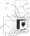
優れた技術があれば、前述の発明を利用した手段に様々な用途が見つけられるだろう。そのような用途はそれぞれ十分、本発明の範囲内と見なされるべきである。発明の数多くの用途の一例を図3〜5及び図9に示し、ここでは表示器10はグリーティング・カード、招待状、通知、広告、カードとして考えうる種類の他の全てのカードの形となっている。図3では表示器10の組み立て前の形を第一面から示している。図4も表示器10が組み立てられる前の形を示しているが、第二面から見たものである。図5は一部組み立てられた形の表示器10、又図9は表示器10のカード版の変型を示している。
If there is an excellent technology, various uses will be found in the means using the above-mentioned invention. Each such application should be considered well within the scope of the present invention. An example of the many uses of the invention is shown in FIGS. 3-5 and 9, in which the
図3〜5では、表示器10には台紙40があり、一端は動画層18と、また他端は第一表紙パネル38の一端、上の端はシールド・パネル42とつながっている。第一表紙パネル38は他端は第二表紙パネル36の一端とつながっており、第二表紙パネル36の他端はプレッシャー・プレート・キャリア12とつながっている。第一表紙パネル38、第二表紙パネル36、及びシールド・パネル42にはそれぞれ、分解された絵柄26に対応しており、最終的には一致する形の切り抜き窓44がある。図4が示しているように、第二表紙パネル36には、第一表紙パネル38に貼り付けられるよう、のりしろ50を付けてもよい。同様に、台紙40にもシールド・パネル42に貼り付けるためにのりしろ52が付いている。
3 to 5, the
表示器10は従って、パネル36、38、40及び42を折りたたみ貼り付けることで図5に示した構造に組み立てられる。明らかに、図5の動画層18をプレッシャー・プレート14の外側に開いた状態で示してあるのは、表示器10の構造を明確にする目的のみのためである。通常はプレッシャー・プレート14の下に、移動するように取り付けられている。又、分かりやすくするため、図5では覆い24は一部しか示していない。さらに、シールド・パネル42が上に開いた状態になっているのも、分かりやすくするためである。通常はのりしろ52によってプレッシャー・プレート14、動画層18、及び他の表示器10の構成材の上に貼り付けられており、表示器10の画像部分のみが切り抜き窓44から見えるように露出しており、この例ではたまたまハート型になっている。
Accordingly, the
図5から明らかなように、明らかに第二表紙パネル36は第一表紙パネル38より狭い。その結果、第二表紙パネル36より延びるプレッシャー・プレート・キャリア12の端は第一表紙パネル38のちょうつがいの接合を台紙40と置き換える。この置き換えにより、カードの表紙を本質的に構成する第一及び第二表紙パネル38、36により形成される構造の旋回運動が動画層18と関係するプレッシャー・プレート・キャリア12の動きを引き起こし、その結果前述の表示器10の動画表示を引き起こす。
As is apparent from FIG. 5, the
図9から明らかなように、動画層18とプレッシャー・プレート・キャリア12は図3〜5とは基本的に反対側に付けることもできる。具体的には、台紙40は先ほどと同様、第一表紙パネル38及びシールド・パネル42とつながっているが、一端は図3〜5で示したように動画層18とではなく、プレッシャー・プレート・キャリア12とつながっている。動画層18は第二表紙パネル36の他端につながっているため、プレッシャー・プレート・キャリア12と入れ替えることが可能である。表示器10はこれ以外の点は基本的に先ほど説明した実施形態と全く同じである。
As is apparent from FIG. 9, the moving
当然、ここで示している第一及び第二表紙パネル38と36の二つによるプレッシャー・プレート・キャリア12又は動画層18とのつながりが、台紙40に対する第二表紙パネル38とのつながりから外れている状態は、単に見本である。優れた技術があれば、表紙パネルに対しプレッシャー・プレート・キャリア12又は動画層18が開く位置を変える他の手段、例えば第一及び第二表紙パネル38と36の組み合わせによって形成されるものなど様々な手段に気づくだろう。それぞれの手段は本発明の範囲内に入る。
Naturally, the connection between the
分解された絵柄26に対する覆い24の正確な配置と的確な位置合わせ精度は、表示器10が最適な動作をするために重要であることを再び指摘しておきたい。しかし、こうした配置や位置合わせ精度を達成するのは、特に図3〜5及び9の実施形態では難しい。図3と4を再び参照すると、組み立て前にプレッシャー・プレート・キャリア12と動画層18は複数の折り目によって分けられ、こうした折り目は以上の構成材が移動できる関係になるように作られなければならない。覆い24と分解された絵柄26の位置を合わせ、表示器10を適切に開閉するには、動画層18、台紙40、第一表紙パネル38、第二表紙パネル36、及びプレッシャー・プレート・キャリア12の間の折り目の位置と方向が正確でなければならない。覆い24と分解された絵柄26が整列する、あるいは表示器10が適切に開閉するためには、動画層18、台紙40、第一表紙パネル38、第二表紙パネル36、プレッシャー・プレート・キャリア12の間の折り目は位置、方向について正確に作られなければならない。一つの折り目の位置又は方向が不適切であると、残りの折り目の位置又は方向に本質的に影響し、その影響は大きくなる可能性があり、それによって動作しない、或いは動画が適切に動かない表示器10となってしまう。
It should be pointed out again that the correct placement and correct alignment accuracy of the covering 24 with respect to the decomposed
表示器10の折り目の位置と方向を常に正確にするのは、素材が白紙である関係で難しいことが明らかになっている。さらに、打ち抜き加工や他の類似した工程等によって折り目の位置と方向が正確であっても、カード・ストック等の多くの基材の質によって折り目が比較的太く、不正確になってしまう傾向がある。このように太く、不正確な折り目によって、表示器10を組み立て、作動できる正確さは損なわれてしまう。
It has become clear that it is difficult to always make the position and direction of the fold of the
本発明者は実験により、望ましい位置と方向性を備えた基材に一連のミシン目、切り込み、折り目付け、鋸歯状の縁、又はその他直線の変型を表面に施すことで、折り目の正確さと精度を改善できることを発見した。例えば、図3〜5及び9では動画層18、台紙40、第一表紙パネル38、第二表紙パネル36、及びプレッシャー・プレート・キャリア12の間の折り目にはミシン目線45がある。このミシン目線45は正確な位置と方向で付けられている。この線によって、例えば動画層18を台紙40に対して折り曲げると、その間の折り目はミシン目線45にぴったり沿ったものとなりやすい。従って、こうしてできた折り目は直線の表面形状の変型、則ちこの例ではミシン目線45を形成しているミシン目がない場合より細く、正確になる。
The inventor has experimented with applying a series of perforations, cuts, creases, serrated edges, or other linear variations to the surface with the desired location and orientation to ensure the accuracy and accuracy of the folds. I found that I can improve. For example, in FIGS. 3-5 and 9, there is a
表面形状変型の質は利用する基材の質、並びに結果として作り出される製品の望ましい特徴及び耐久性など多くの要因によって変わる可能性がある点は指摘しておきたい。例えば、特定の実施形態、或いは特定の折り目と関連して、比較的大きなミシン目によってミシン目線45を形成できる。しかし、他の実施形態では比較的大きなミシン目によるでこぼこ、又は耐久性の低下は望ましくなく、比較的小さなミシン目を利用することが正しくなる。また、ミシン目は単に見本であり、同様の効果を得るため他の表面形状の変型も利用可能である。
It should be pointed out that the quality of the surface profile can vary depending on many factors such as the quality of the substrate used and the desired characteristics and durability of the resulting product. For example, the
繰り返しになるが、この発明を利用したさらに多くの実施形態が可能である。図6と7では表示器10の代替構造を示しており、表示器10は基本的に、プレッシャー・プレート14とプレッシャー・プレート・キャリアという二つの部分のみで形成でき、この二つを台紙部分15と名付ける。台紙部分15の素材は堅いパネルで、両端が滑らかであっても良い。特定の例では、台紙部分15はカードでも良く、例えばクレジット・カード、広告用カード、会員カード、ギフト・カード、身分証明書、ノベルティ・カード、及びその他いかなる種類のカードでも良い。プレッシャー・プレート14も、台紙部分15に隣接している面と密着させるために中央部分を傾斜させる目的で付勢機構(20、22)を台紙部分15の端の近くに付けても良い。
Again, many more embodiments utilizing the present invention are possible. FIGS. 6 and 7 show an alternative structure of the
図6で示しているように、プレッシャー・プレート14は特定の実施形態では台紙部分15を完全に覆い、両方の遠位端を合わせて貼り付けることができる。或いは、図7のように、プレッシャー・プレート14に台紙部分15の端の上にかぶせる簡単なクリップ部分11と13を付けることもできる。いずれの場合でも、分解された絵柄26はプレッシャー・プレート14、又は隣接した台紙部分15の面に付け、覆い24はもう一方のプレッシャー・プレート14と台紙部分15に付けられる。こうした構造では、プレッシャー・プレート14を台紙部分15に対して単に移動させることで、プレッシャー・プレート14と台紙部分15間の密接な接触と正確な位置合わせによって動画を表すことができる。
As shown in FIG. 6, the
表示器10の表示面と言える面にある第一と第二の付勢機構(20、22)は、プレッシャー・プレート14の画像部分と台紙部分15の間の十分な接触を生み出す。しかし、特定の実施形態では、第三、そして場合によっては第四の付勢機構21と23を表示器10の背面に付けることで、さらに密着させられる。こうした構造を表したのが図8である。ここではプレッシャー・プレート14が台紙部分15を完全に覆っており、第三と第四の付勢機構21と23が表示器10の背面の端近くに形成されている。第三と第四の付勢機構21と23は第一と第二の付勢機構20、22と共にプレッシャー・プレート14の表示部分と台紙部分15の間の密着の度合いを高められる。ここでも、付勢機構20、21、22と23はプレッシャー・プレート14を延長した折り目として示している。しかし、本発明の範囲内の様々な形で同じ効果をもたらすことができる。
The first and second biasing mechanisms (20, 22) on the display surface of the
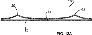
さらに表示器10の変型でプレッシャー・プレート14とプレッシャー・プレート・キャリア12が一体となって台紙部分15となり、動画を作り出すものを図10〜12、13A、及び13Bに示している。プレッシャー・プレート14にはここでもプレッシャー・プレート14の動画部分と台紙部分15の間を完全に接触させるため、第一と第二の付勢機構(20、22)付いている。しかし、付勢機構20と22はプレッシャー・プレート14の両端近くに作られており、台紙部分15に対するプレッシャー・プレート14の移動経路に対し一般的に垂直となっている。
Further, FIGS. 10 to 12, 13 </ b> A, and 13 </ b> B show a modification of the
プレッシャー・プレート14には複数のツメ54がヘッダー部分58とフッター部分60から内向きに突出している。ツメ54は通常、台紙部分15の幅よりやや外側から台紙部分15よりやや内側の位置に、向かい合って飛び出している。これによってツメ54が台紙部分15の背面に配置される一方、プレッシャー・プレート14の本体部分は台紙15の表示面に置かれることによって、プレッシャー・プレート14は台紙部分15と移動可能な状態で関わることができる。
The
図12、13Aと13Bを合わせて参照すると、利用者が表示器10を左手と右手100Aと100Bで持ち、親指102Aと102Bをできれば位置表示マーク55と56(付勢機構(20、22)の中央部)の上、或いはその近くに置くことで表示器10の動画が表示されることが分かる。利用者が位置表示記号55と56を押すことで、表示器10を図13Aの圧迫していない状態から図13Bの圧迫した状態にできる。表示器10をこのように押すと、プレッシャー・プレート14の動画部分と台紙部分15は、位置表示記号55と56が押されることに加えて、向かい合ったツメ54の力によって完全に密着する。その後、プレッシャー・プレート14を台紙部分15に対し移動させることで鮮明な動画を実現できる。
Referring to FIGS. 12, 13A and 13B together, the user holds the
可動式動画表示器10の複数の実施形態の見本及び本発明の詳細を示したことで、発明の精神或いは範囲から逸脱することなく様々な変更及び追加ができることが高い技術を持った人には理解されるだろう。現在の好ましい実施形態は単にここで示した広範な発明を体現しているにすぎない点を心に留めて頂ければ尚更である。発明の主な特徴を念頭に置いている人は、こうした主な特徴を持ちつつ、好ましい実施形態に含まれている全ての特徴は採用せずに実施形態を制作することが可能であろう。
For those skilled in the art, it is possible to make various changes and additions without departing from the spirit or scope of the invention by showing a sample of a plurality of embodiments of the movable moving
従って、以下の特許請求の範囲は発明者に与えられた保護の範囲を規定することを意図している。こうした特許請求の範囲には、発明の精神及び領域から逸脱しない範囲で同等の構造を含むと判断される。さらに複数の以下の特許請求の範囲は、時には構造や材料の詳説なしに、特定の機能を果たす手段として特定の構成部分について述べる可能性がある点にも触れておく。法律が定めているように、こうした特許請求の範囲の構成部分は本明細書で明確に説明しているものと一致している構造及び材料を対象としているのみならず、全ての同等物を対象としているものと解釈される。 Accordingly, the following claims are intended to define the scope of protection conferred upon the inventor. Such claims are deemed to include equivalent structures without departing from the spirit and scope of the invention. Furthermore, the following claims also note that certain components may be described as a means for performing a specific function, sometimes without detailed description of structure or material. As required by law, the components of these claims cover not only structures and materials consistent with those explicitly described herein, but also all equivalents. It is interpreted as.
Claims (30)
前記表示器(10)の表示面と相対する背面とを有するプレッシャー・プレート・キャリア(12、15);
プレッシャー・プレート・キャリア(12、15)に固定された第一端、前記第一端に相対する、プレッシャー・プレート・キャリア(12、15)に固定された第二端、及び前記第一端と第二端の間の本体部を有し、プレッシャー・プレート・キャリア(12、15)につながれるプレッシャー・プレート(14);
複数の分解された絵柄(26);
複数の不透明部分を含み、複数の隙間を有する覆い(24)で、前記覆い(24)は、
前記複数の隙間に前記複数の分解された絵柄(26)が介在し、プレッシャー・プレート(14)と組み合わせて、プレッシャー・プレート・キャリア(12、15)により、複数の分解された絵柄(26)に対し移動可能なよう保持され、複数の覆い(24)と複数の分解された絵柄(26)が可動式動画表示器(10)のプレッシャー・プレート・キャリア(12、15)の表示面に取り付けられており、複数の分解された絵柄(26)と複数の覆い(24)が相互の関係によって移動し、可動式動画表示器(10)の動画を動画部分に作り出す、複数の覆い(24);及び
少なくともプレッシャー・プレート(14)の一部にプレッシャー・プレート・キャリア(12、15)方向の傾斜を作るため、プレッシャー・プレート(14)の第一端および第二端から離れて位置するプレッシャー・プレート(14)に形成される折り目を含む、プレッシャー・プレート(14)の本体部に少なくとも一つの付勢機構(20、21、22、23);を備える可動式動画表示器(10)。A movable video display (10) for displaying a plurality of images, wherein the display (10) is:
A pressure plate carrier (12, 15) having a back surface opposite to the display surface of the indicator (10);
A first end fixed to the pressure plate carrier (12, 15), a second end fixed to the pressure plate carrier (12, 15) opposite the first end, and the first end; A pressure plate (14) having a body between the second ends and connected to a pressure plate carrier (12, 15);
Multiple decomposed patterns (26);
A cover (24) comprising a plurality of opaque portions and having a plurality of gaps, wherein said cover (24)
Wherein the plurality of decomposed picture (26) is interposed in said plurality of gap, in combination with the pressure plate (14), by the pressure plate carrier (12, 15), a plurality of decomposed picture (26) Multiple covers (24) and multiple disassembled pictures (26) are attached to the display surface of the pressure plate carrier (12, 15) of the movable video display (10) A plurality of covers (24) that create a video of the moving video display (10) in the video part by moving the disassembled pattern (26) and the plurality of covers (24) in relation to each other. And a pressure located away from the first and second ends of the pressure plate (14) to create an inclination in the direction of the pressure plate carrier (12, 15) on at least a portion of the pressure plate (14).・ Shape on plate (14) Is the containing folds, at least one of the biasing mechanism to the main body portion of the pressure plate (14) (20, 21, 22, 23); movable moving indicator with (10).
プレッシャー・プレート・キャリア(12、15)に固定された第一端、前記第一端に相対する、プレッシャー・プレート・キャリア(12、15)に固定された第二端、及び前記第一端と第二端の間の本体部を有し、プレッシャー・プレート・キャリア(12、15)につながるプレッシャー・プレート(14);
複数の分解された絵柄(26);
複数の不透明部分を含み、複数の隙間を有し、前記複数の隙間に前記複数の分解された絵柄(26)が介在し、プレッシャー・プレート(14)と組み合わせて、プレッシャー・プレート・キャリア(12、15)により、複数の分解された絵柄(26)に対し移動可能なように保持され、複数の覆い(24)と複数の分解された絵柄(26)が可動式動画表示器(10)のプレッシャー・プレート・キャリア(12、15)の表示面に取り付けられており、複数の分解された絵柄(26)と複数の覆い(24)が相互の関係によって移動し、可動式動画表示器(10)の動画を前記表示面にある動画部分に作り出し、プレッシャー・プレート・キャリア(12、15)は、前記表示面に相対する背面を有する、複数の覆い(24);及び
可動式動画表示器(10)の動画部分の外側と背面に形成され、プレッシャー・プレート・(14)の第一端と第二端から離れて位置する、プレッシャー・プレート(14)の本体部にある、第一と第二の付勢機構(20、21、22、23);
を備える複数の画像を表示するための可動式動画表示装置(10)。Pressure plate carrier (12, 15);
A first end fixed to the pressure plate carrier (12, 15), a second end fixed to the pressure plate carrier (12, 15) opposite the first end, and the first end; A pressure plate (14) having a body between the second ends and leading to a pressure plate carrier (12, 15);
Multiple decomposed patterns (26);
Look including a plurality of opaque portions, a plurality of gaps, said plurality of decomposed picture (26) is interposed in said plurality of gap, in combination with the pressure plate (14), the pressure plate carrier ( 12 and 15) are held so as to be movable with respect to a plurality of disassembled patterns (26), and a plurality of covers (24) and a plurality of disassembled patterns (26) are movable video display (10) Is attached to the display surface of the pressure plate carrier (12, 15), and a plurality of disassembled patterns (26) and a plurality of covers (24) move according to the mutual relationship, and a movable video display ( 10) moving image on the display surface, the pressure plate carrier (12, 15) having a back surface facing the display surface, a plurality of covers (24); and a movable moving image display (10) is formed on the outside and back of the video part, The first and second urging mechanisms (20, 21, 22, 23) in the main body of the pressure plate (14), which are located away from the first and second ends of the shear plate (14) );
A movable video display device (10) for displaying a plurality of images.
隣接した一端と他端があり、ヒンジ接続部により台紙(40)と回転可能につながっている、折りたたまれかつ接着された第一及び第二表紙パネル(36、38);
台紙(40)と第一及び第二表紙パネル(36、38)をつなぐヒンジ接続部から離れて位置するヒンジ接続部で、台紙(40)と回転可能につながっている第一パネル(18);
台紙(40)と第一及び第二表紙パネル(36、38)とをつなぐヒンジ接続部から離れて位置するヒンジ接続部で第一及び第二表紙パネル(36、38)と回転可能につながっており、第二表紙パネル(36)の両側にあるミシン目線間の幅を第一表紙パネル(38)の両側にあるミシン目線間の幅より狭くすることにより、第一及び第二表紙パネル(36、38)が台紙(40)に対し回転することで、第一パネルと第二パネル(12、18)が重なる関係にある場合、第一パネル(18)に対する相対的なスライド移動を引き起こす、第二パネル(12);
第一パネル(18)又は第二パネル(12)の一方に保持される複数の分解された絵柄(26);そして
複数の不透明部分を含み、複数の隙間を有し、前記複数の隙間に前記複数の分解された絵柄(26)が介在し、第一パネル(18)又は第二パネル(12)のもう一方に保持される、複数の覆い(24);
を備える複数の画像を表示するための動画表示装置(10)であって、
第二パネル(12)に対する第一パネル(18)の相対的な動きが可動式動画表示器(10)の動画を動画部分に作り出し、第一パネル(18)は台紙(40)に対して回転することができ、第二パネル(12)は第一及び第二表紙パネル(36、38)に対して回転することができ、第一及び第二表紙パネル(36、38)が台紙(40)に対して回転する場合、第一パネルと第二のパネル(12、18)は平坦かつほぼ並行関係に維持されることができる動画表示器(10)。Mount with adjacent one and other ends (40);
Folded and bonded first and second cover panels (36, 38) having adjacent one and other ends and rotatably connected to the mount (40) by a hinge connection;
A first panel (18) rotatably connected to the mount (40) at a hinge connection located away from the hinge connection connecting the mount (40) and the first and second cover panels (36, 38);
A hinge connection part located away from the hinge connection part that connects the mount (40) and the first and second cover panels (36, 38), and is rotatably connected to the first and second cover panels (36, 38). The width between the perforation lines on both sides of the second cover panel (36) is made narrower than the width between the perforation lines on both sides of the first cover panel (38), so that the first and second cover panels (36 , 38) is rotated with respect to the mount (40), and when the first panel and the second panel (12, 18) are in an overlapping relationship, the first panel (18) is caused to slide relative to the first panel (18). Two panels (12);
A plurality of disassembled pictures (26) held on one of the first panel (18) or the second panel (12); and
It includes a plurality of opaque portions, has a plurality of gaps, and the plurality of disassembled patterns (26) intervene in the plurality of gaps, and the other of the first panel (18) or the second panel (12) Multiple covers (24) retained;
A video display device (10) for displaying a plurality of images comprising:
The relative movement of the first panel (18) relative to the second panel (12) creates a moving image of the movable video display (10) in the video part, and the first panel (18) rotates relative to the backing (40) it is possible to, the second panel (12) can rotate relative to the first and second cover panels (36, 38), the first and second cover panels (36, 38) is mount (40) When rotating with respect to the moving image display (10), the first panel and the second panel (12, 18) can be maintained in a flat and substantially parallel relationship.
Applications Claiming Priority (2)
| Application Number | Priority Date | Filing Date | Title |
|---|---|---|---|
| US53489404P | 2004-01-08 | 2004-01-08 | |
| PCT/US2005/000460 WO2005070075A2 (en) | 2004-01-08 | 2005-01-07 | Moveable animated display device |
Publications (2)
| Publication Number | Publication Date |
|---|---|
| JP2007526500A JP2007526500A (en) | 2007-09-13 |
| JP4572202B2 true JP4572202B2 (en) | 2010-11-04 |
Family
ID=34806886
Family Applications (1)
| Application Number | Title | Priority Date | Filing Date |
|---|---|---|---|
| JP2006549425A Expired - Fee Related JP4572202B2 (en) | 2004-01-08 | 2005-01-07 | Movable video display |
Country Status (3)
| Country | Link |
|---|---|
| US (1) | US7151541B2 (en) |
| JP (1) | JP4572202B2 (en) |
| WO (1) | WO2005070075A2 (en) |
Families Citing this family (49)
| Publication number | Priority date | Publication date | Assignee | Title |
|---|---|---|---|---|
| US7959437B2 (en) | 2002-10-29 | 2011-06-14 | Rmo, Inc. | Orthodontic appliance with encoded information formed in the base |
| US7695277B1 (en) | 2004-10-28 | 2010-04-13 | Rmo, Inc. | Orthodontic bracket with frangible cover mechanism |
| JP2009532134A (en) * | 2006-03-31 | 2009-09-10 | アールエムオー,インコーポレイテツド | Orthodontic bracket with liner archwire slot and cover |
| US8979528B2 (en) | 2006-09-07 | 2015-03-17 | Rmo, Inc. | Customized orthodontic appliance method and system |
| US9554875B2 (en) | 2006-09-07 | 2017-01-31 | Rmo, Inc. | Method for producing a customized orthodontic appliance |
| US8251697B2 (en) | 2006-09-07 | 2012-08-28 | Rmo, Inc. | Reduced-friction buccal tube and method of use |
| US7359120B1 (en) * | 2006-11-10 | 2008-04-15 | Genie Lens Technologies, Llc | Manufacture of display devices with ultrathin lens arrays for viewing interlaced images |
| US7480100B1 (en) | 2007-10-15 | 2009-01-20 | Genie Lens Technologies, Llc | Lenticular devices using sets of lenses to display paired sets of interlaces of images |
| US20090126242A1 (en) * | 2007-11-20 | 2009-05-21 | Americhip Technologies, Llc | Thin motorized novelty device |
| JP5304056B2 (en) * | 2008-07-01 | 2013-10-02 | 大日本印刷株式会社 | Packaging box |
| JP5239557B2 (en) * | 2008-07-01 | 2013-07-17 | 大日本印刷株式会社 | Packaging box |
| US7836620B2 (en) * | 2008-07-21 | 2010-11-23 | Andrews McMeel Publishing, LLC | Animated media and methods of construction |
| US7810261B2 (en) * | 2008-07-24 | 2010-10-12 | Americhip, Inc. | Animated foldable card |
| US20100052934A1 (en) * | 2008-08-27 | 2010-03-04 | Americhip, Inc. | Novelty video device and method |
| USD654113S1 (en) | 2008-08-27 | 2012-02-14 | Americhip, Inc. | Multi-spread video book |
| USD691194S1 (en) | 2008-08-27 | 2013-10-08 | Americhip, Inc. | Printed media insert |
| USD647559S1 (en) | 2008-08-27 | 2011-10-25 | Americhip, Inc. | Video book |
| USD643060S1 (en) | 2008-08-27 | 2011-08-09 | Americhip, Inc. | Video insert |
| USD655750S1 (en) | 2008-08-27 | 2012-03-13 | Americhip, Inc. | Video trading card |
| USD642611S1 (en) | 2008-08-27 | 2011-08-02 | Americhip, Inc. | Video book |
| US20100052876A1 (en) * | 2008-08-27 | 2010-03-04 | Americhip, Inc. | Novelty device and method |
| US8011122B2 (en) * | 2008-08-27 | 2011-09-06 | Americhip, Inc. | Novelty video device and method |
| JP5169692B2 (en) * | 2008-09-29 | 2013-03-27 | 大日本印刷株式会社 | Special signatures that produce movies, and booklets with them |
| JP5223569B2 (en) * | 2008-09-29 | 2013-06-26 | 大日本印刷株式会社 | Booklet with decorative elements that produce a video |
| FR2940179B1 (en) | 2008-12-23 | 2017-06-02 | Arjowiggins | SECURITY DOCUMENT COMPRISING AT LEAST ONE COMBINED IMAGE AND A REVELATION MEANS, AND ASSOCIATED METHOD. |
| JP5243986B2 (en) * | 2009-02-09 | 2013-07-24 | 凸版印刷株式会社 | Variable image display |
| US11219507B2 (en) | 2009-03-16 | 2022-01-11 | Orthoamerica Holdings, Llc | Customized orthodontic appliance and method |
| WO2010107567A1 (en) | 2009-03-16 | 2010-09-23 | Rmo, Inc. | Orthodontic bracket having an archwire channel and archwire retaining mechanism |
| FR2948217B1 (en) | 2009-07-17 | 2011-11-11 | Arjowiggins Security | SECURITY ELEMENT WITH PARALLAX EFFECT |
| FR2948216B1 (en) | 2009-07-17 | 2011-11-25 | Arjowiggins Security | SECURITY ELEMENT WITH PARALLAX EFFECT |
| US8546301B2 (en) | 2010-06-11 | 2013-10-01 | Ws Packaging Group, Inc. | On-demand printable construct |
| JP2012000965A (en) * | 2010-06-21 | 2012-01-05 | Liberal:Kk | Book with printed image appearing to move |
| FR2961622B1 (en) | 2010-06-22 | 2013-02-08 | Arjowiggins Security | METHOD FOR AUTHENTICATION AND / OR IDENTIFICATION OF A SECURITY ARTICLE |
| FR2961621B1 (en) | 2010-06-22 | 2014-09-05 | Arjowiggins Security | METHOD OF AUTHENTICATING AND / OR IDENTIFYING A SECURITY ARTICLE |
| US9213428B2 (en) * | 2010-11-19 | 2015-12-15 | Blackberry Limited | Portable electronic device including flexible display |
| US8919018B2 (en) | 2011-01-31 | 2014-12-30 | HJovic Design LLC | Method and apparatus for card image transformation and content securing |
| EP2706949B1 (en) | 2011-05-12 | 2019-11-13 | Rmo, Inc. | Orthodontic appliance with encoded information formed in the base |
| USD847349S1 (en) | 2011-09-22 | 2019-04-30 | Rmo, Inc. | Orthodontic lock with flange |
| US9043195B2 (en) | 2011-09-26 | 2015-05-26 | Jaclyn Paris | Systems and methods for teaching phonemic awareness |
| US9478153B1 (en) | 2013-02-27 | 2016-10-25 | Rufus Butler Seder | Illuminated cylindrical animation device |
| US20140270577A1 (en) * | 2013-03-14 | 2014-09-18 | Pouch Pac Innovations, Llc | Pouch with lenticular image |
| WO2015058794A1 (en) | 2013-10-23 | 2015-04-30 | Aktiebolaget Skf | Bearing product |
| US9210321B2 (en) * | 2013-12-05 | 2015-12-08 | Here Global B.V. | Method and apparatus for a shutter animation for image capture |
| US9734768B1 (en) | 2014-02-14 | 2017-08-15 | Ted Shapiro | User-manipulated coded image display and animation system |
| US20150243258A1 (en) * | 2014-02-24 | 2015-08-27 | Disney Enterprises, Inc. | Transparent gift card for overlaying a digital display |
| US9555340B2 (en) | 2014-12-30 | 2017-01-31 | Rufus Butler Seder | Manually posable figure animation system and method |
| US9488903B1 (en) | 2015-07-13 | 2016-11-08 | Christine Veras de Souza | Silhouette zoetrope |
| FR3046110B1 (en) * | 2015-12-29 | 2022-03-25 | Arjowiggins Security | SECURE ARTICLE CONTAINING A COMBINED IMAGE AND/OR A REVELATION FRAME |
| US11604405B2 (en) | 2018-07-20 | 2023-03-14 | Rufus Butler Seder | Manually-operated coded image animation device |
Family Cites Families (25)
| Publication number | Priority date | Publication date | Assignee | Title |
|---|---|---|---|---|
| US2374371A (en) | 1945-04-24 | Apparatus for the animating of | ||
| US1285753A (en) | 1914-10-16 | 1918-11-26 | Harry F Loewenstein | Changeable-picture device. |
| US1259297A (en) | 1915-12-31 | 1918-03-12 | Winfield S Russell | Picture-display holder. |
| US1474572A (en) | 1921-05-18 | 1923-11-20 | Otto M Whitstock | Changeable-picture device |
| US2085803A (en) | 1936-02-14 | 1937-07-06 | Thaddeus G Harrison | Advertising device |
| US2367967A (en) * | 1942-11-18 | 1945-01-23 | Schwartz Edward | Animated picture device |
| US2398257A (en) | 1943-02-13 | 1946-04-09 | Schwartz Edward | Package label |
| US2528765A (en) * | 1947-01-04 | 1950-11-07 | Jr John E Lindberg | Pocket sketching set |
| US3268238A (en) | 1964-06-03 | 1966-08-23 | Finkel Richard | Publications |
| US3314179A (en) | 1965-04-05 | 1967-04-18 | Sam L Leach | Display apparatus |
| US3643361A (en) | 1969-11-17 | 1972-02-22 | Photo Motion Corp | Moire motion illusion apparatus |
| US3862504A (en) | 1972-04-26 | 1975-01-28 | Harry M Ringelheim | Visual display apparatus |
| US4118879A (en) | 1977-02-10 | 1978-10-10 | Thomas A. Schutz Co., Inc. | Animated display device having a curved platen and a movable film |
| US4789573A (en) | 1987-10-13 | 1988-12-06 | Jenkinson Anthony N | Device for producing variable moire patterns |
| US4885193A (en) | 1987-11-02 | 1989-12-05 | Head Richard M | Art form and method of producing same |
| US5695346A (en) | 1989-12-07 | 1997-12-09 | Yoshi Sekiguchi | Process and display with moveable images |
| US5782026A (en) | 1994-12-05 | 1998-07-21 | Capie; John | Back lit multi image transparency |
| US5823344A (en) | 1995-07-31 | 1998-10-20 | Insight, Inc. | Display systems with multiple view optics |
| JPH11327479A (en) * | 1998-05-20 | 1999-11-26 | Takao Yoguchi | Sliding type image change display device |
| US5901484A (en) | 1998-06-09 | 1999-05-11 | Seder; Rufus Butler | Manually operated moveable display device |
| US6286873B1 (en) | 1998-08-26 | 2001-09-11 | Rufus Butler Seder | Visual display device with continuous animation |
| JP2004506926A (en) * | 2000-06-23 | 2004-03-04 | サブメディア, エルエルシー | Display of a still image that makes a moving viewer look like a moving image |
| JP2002162905A (en) * | 2000-11-28 | 2002-06-07 | Panefuri Kogyo Kk | Mounting structure for card holder |
| US7000343B1 (en) * | 2002-04-16 | 2006-02-21 | Teichman Terrence J | Flexible platen image display device and method |
| US6781761B2 (en) * | 2002-08-29 | 2004-08-24 | Mark A. Raymond | Lenticular lens system and method for use in producing images with clear-walled containers |
-
2005
- 2005-01-07 US US11/031,873 patent/US7151541B2/en active Active
- 2005-01-07 JP JP2006549425A patent/JP4572202B2/en not_active Expired - Fee Related
- 2005-01-07 WO PCT/US2005/000460 patent/WO2005070075A2/en active Search and Examination
Also Published As
| Publication number | Publication date |
|---|---|
| JP2007526500A (en) | 2007-09-13 |
| US20050183300A1 (en) | 2005-08-25 |
| WO2005070075A2 (en) | 2005-08-04 |
| US7151541B2 (en) | 2006-12-19 |
| WO2005070075A3 (en) | 2007-06-14 |
Similar Documents
| Publication | Publication Date | Title |
|---|---|---|
| JP4572202B2 (en) | Movable video display | |
| US5901484A (en) | Manually operated moveable display device | |
| JP3839458B1 (en) | Self-supporting flat plate, display method and manufacturing method thereof | |
| US5710666A (en) | Slide viewer having a lenticular viewing lens | |
| US6843009B2 (en) | Lenticular folding card, card case, and book | |
| US7234257B2 (en) | Means for maintaining spatial relationships in lenticular display units | |
| TWI250094B (en) | Rotary multi-functional trimming apparatus | |
| US4819354A (en) | One-piece foldable frame assembly | |
| JP2010228340A (en) | Moving image sheet and moving image book | |
| JP3878659B1 (en) | Method for producing self-supporting flat plate | |
| US20050223605A1 (en) | Display arrangement | |
| JP2017156738A (en) | Stereoscopic image display device and sheet member thereof | |
| JP2006003410A (en) | Storage bag for photographic prints | |
| GB2192085A (en) | Pattern display device | |
| US20050039366A1 (en) | Picture frame | |
| JP2003159892A (en) | Index label sheet | |
| EP1005009A1 (en) | Method for manufacturing a display device. | |
| JP2022123172A (en) | positioning scale | |
| JP2008246709A (en) | Photographic album and preparing system of the same | |
| US4523399A (en) | Display mount apparatus and method | |
| JP3908533B2 (en) | Booklet flyer | |
| JP3185160U (en) | Stamping / joining-type stamps provided with anti-slip material, and stamps constituting the coupling-type stamping tool | |
| JP2022025679A (en) | Transparent screen | |
| JP4459502B2 (en) | Manufacturing method of leaflet with appendix | |
| EP0031848A1 (en) | Indicia bearing geometric instrument |
Legal Events
| Date | Code | Title | Description |
|---|---|---|---|
| A621 | Written request for application examination |
Free format text: JAPANESE INTERMEDIATE CODE: A621 Effective date: 20071128 |
|
| A871 | Explanation of circumstances concerning accelerated examination |
Free format text: JAPANESE INTERMEDIATE CODE: A871 Effective date: 20090512 |
|
| A131 | Notification of reasons for refusal |
Free format text: JAPANESE INTERMEDIATE CODE: A131 Effective date: 20090623 |
|
| A601 | Written request for extension of time |
Free format text: JAPANESE INTERMEDIATE CODE: A601 Effective date: 20090917 |
|
| A602 | Written permission of extension of time |
Free format text: JAPANESE INTERMEDIATE CODE: A602 Effective date: 20090929 |
|
| A601 | Written request for extension of time |
Free format text: JAPANESE INTERMEDIATE CODE: A601 Effective date: 20091022 |
|
| A521 | Request for written amendment filed |
Free format text: JAPANESE INTERMEDIATE CODE: A523 Effective date: 20091029 |
|
| A602 | Written permission of extension of time |
Free format text: JAPANESE INTERMEDIATE CODE: A602 Effective date: 20091029 |
|
| A521 | Request for written amendment filed |
Free format text: JAPANESE INTERMEDIATE CODE: A523 Effective date: 20091204 |
|
| A975 | Report on accelerated examination |
Free format text: JAPANESE INTERMEDIATE CODE: A971005 Effective date: 20100125 |
|
| A131 | Notification of reasons for refusal |
Free format text: JAPANESE INTERMEDIATE CODE: A131 Effective date: 20100302 |
|
| A601 | Written request for extension of time |
Free format text: JAPANESE INTERMEDIATE CODE: A601 Effective date: 20100528 |
|
| A602 | Written permission of extension of time |
Free format text: JAPANESE INTERMEDIATE CODE: A602 Effective date: 20100604 |
|
| A521 | Request for written amendment filed |
Free format text: JAPANESE INTERMEDIATE CODE: A523 Effective date: 20100701 |
|
| TRDD | Decision of grant or rejection written | ||
| A01 | Written decision to grant a patent or to grant a registration (utility model) |
Free format text: JAPANESE INTERMEDIATE CODE: A01 Effective date: 20100810 |
|
| A01 | Written decision to grant a patent or to grant a registration (utility model) |
Free format text: JAPANESE INTERMEDIATE CODE: A01 |
|
| A61 | First payment of annual fees (during grant procedure) |
Free format text: JAPANESE INTERMEDIATE CODE: A61 Effective date: 20100816 |
|
| FPAY | Renewal fee payment (event date is renewal date of database) |
Free format text: PAYMENT UNTIL: 20130820 Year of fee payment: 3 |
|
| R150 | Certificate of patent or registration of utility model |
Free format text: JAPANESE INTERMEDIATE CODE: R150 |
|
| R250 | Receipt of annual fees |
Free format text: JAPANESE INTERMEDIATE CODE: R250 |
|
| R250 | Receipt of annual fees |
Free format text: JAPANESE INTERMEDIATE CODE: R250 |
|
| LAPS | Cancellation because of no payment of annual fees |