JP4567120B2 - Nitric oxide-accumulating substance and nitric oxide-accumulating catalyst produced therefrom - Google Patents
Nitric oxide-accumulating substance and nitric oxide-accumulating catalyst produced therefrom Download PDFInfo
- Publication number
- JP4567120B2 JP4567120B2 JP23604899A JP23604899A JP4567120B2 JP 4567120 B2 JP4567120 B2 JP 4567120B2 JP 23604899 A JP23604899 A JP 23604899A JP 23604899 A JP23604899 A JP 23604899A JP 4567120 B2 JP4567120 B2 JP 4567120B2
- Authority
- JP
- Japan
- Prior art keywords
- oxide
- accumulating
- nitric oxide
- catalyst
- barium
- Prior art date
- Legal status (The legal status is an assumption and is not a legal conclusion. Google has not performed a legal analysis and makes no representation as to the accuracy of the status listed.)
- Expired - Lifetime
Links
- 239000003054 catalyst Substances 0.000 title claims description 120
- 239000000126 substance Substances 0.000 title claims description 27
- MWUXSHHQAYIFBG-UHFFFAOYSA-N nitrogen oxide Inorganic materials O=[N] MWUXSHHQAYIFBG-UHFFFAOYSA-N 0.000 claims description 128
- 239000000463 material Substances 0.000 claims description 113
- 229910000420 cerium oxide Inorganic materials 0.000 claims description 66
- BMMGVYCKOGBVEV-UHFFFAOYSA-N oxo(oxoceriooxy)cerium Chemical compound [Ce]=O.O=[Ce]=O BMMGVYCKOGBVEV-UHFFFAOYSA-N 0.000 claims description 65
- 238000003860 storage Methods 0.000 claims description 57
- 229910052845 zircon Inorganic materials 0.000 claims description 52
- 239000012876 carrier material Substances 0.000 claims description 43
- 239000002245 particle Substances 0.000 claims description 43
- GFQYVLUOOAAOGM-UHFFFAOYSA-N zirconium(iv) silicate Chemical compound [Zr+4].[O-][Si]([O-])([O-])[O-] GFQYVLUOOAAOGM-UHFFFAOYSA-N 0.000 claims description 38
- 229910052684 Cerium Inorganic materials 0.000 claims description 36
- 238000001354 calcination Methods 0.000 claims description 33
- TWNQGVIAIRXVLR-UHFFFAOYSA-N oxo(oxoalumanyloxy)alumane Chemical compound O=[Al]O[Al]=O TWNQGVIAIRXVLR-UHFFFAOYSA-N 0.000 claims description 28
- 239000011232 storage material Substances 0.000 claims description 27
- IJGRMHOSHXDMSA-UHFFFAOYSA-N Atomic nitrogen Chemical compound N#N IJGRMHOSHXDMSA-UHFFFAOYSA-N 0.000 claims description 22
- BASFCYQUMIYNBI-UHFFFAOYSA-N platinum Chemical compound [Pt] BASFCYQUMIYNBI-UHFFFAOYSA-N 0.000 claims description 22
- 238000004519 manufacturing process Methods 0.000 claims description 20
- 238000000034 method Methods 0.000 claims description 20
- 229910052788 barium Inorganic materials 0.000 claims description 19
- 238000000576 coating method Methods 0.000 claims description 19
- 238000005470 impregnation Methods 0.000 claims description 19
- 239000011248 coating agent Substances 0.000 claims description 18
- DSAJWYNOEDNPEQ-UHFFFAOYSA-N barium atom Chemical compound [Ba] DSAJWYNOEDNPEQ-UHFFFAOYSA-N 0.000 claims description 16
- 238000001035 drying Methods 0.000 claims description 16
- 239000002243 precursor Substances 0.000 claims description 16
- 239000006185 dispersion Substances 0.000 claims description 14
- 238000000975 co-precipitation Methods 0.000 claims description 13
- MMKQUGHLEMYQSG-UHFFFAOYSA-N oxygen(2-);praseodymium(3+) Chemical compound [O-2].[O-2].[O-2].[Pr+3].[Pr+3] MMKQUGHLEMYQSG-UHFFFAOYSA-N 0.000 claims description 13
- 229910003447 praseodymium oxide Inorganic materials 0.000 claims description 13
- 238000001556 precipitation Methods 0.000 claims description 12
- 239000007864 aqueous solution Substances 0.000 claims description 11
- 229910052757 nitrogen Inorganic materials 0.000 claims description 11
- QVGXLLKOCUKJST-UHFFFAOYSA-N atomic oxygen Chemical compound [O] QVGXLLKOCUKJST-UHFFFAOYSA-N 0.000 claims description 10
- 150000001875 compounds Chemical class 0.000 claims description 10
- 239000001301 oxygen Substances 0.000 claims description 10
- 229910052760 oxygen Inorganic materials 0.000 claims description 10
- VYPSYNLAJGMNEJ-UHFFFAOYSA-N Silicium dioxide Chemical compound O=[Si]=O VYPSYNLAJGMNEJ-UHFFFAOYSA-N 0.000 claims description 9
- 239000000395 magnesium oxide Substances 0.000 claims description 9
- CPLXHLVBOLITMK-UHFFFAOYSA-N magnesium oxide Inorganic materials [Mg]=O CPLXHLVBOLITMK-UHFFFAOYSA-N 0.000 claims description 9
- AXZKOIWUVFPNLO-UHFFFAOYSA-N magnesium;oxygen(2-) Chemical compound [O-2].[Mg+2] AXZKOIWUVFPNLO-UHFFFAOYSA-N 0.000 claims description 9
- 229910052751 metal Inorganic materials 0.000 claims description 9
- 239000002184 metal Substances 0.000 claims description 9
- 229910052697 platinum Inorganic materials 0.000 claims description 9
- 239000007789 gas Substances 0.000 claims description 8
- 238000002485 combustion reaction Methods 0.000 claims description 6
- 229910052712 strontium Inorganic materials 0.000 claims description 6
- CIOAGBVUUVVLOB-UHFFFAOYSA-N strontium atom Chemical compound [Sr] CIOAGBVUUVVLOB-UHFFFAOYSA-N 0.000 claims description 6
- 230000003647 oxidation Effects 0.000 claims description 5
- 238000007254 oxidation reaction Methods 0.000 claims description 5
- 230000002829 reductive effect Effects 0.000 claims description 5
- 229910052703 rhodium Inorganic materials 0.000 claims description 5
- 239000010948 rhodium Substances 0.000 claims description 5
- MHOVAHRLVXNVSD-UHFFFAOYSA-N rhodium atom Chemical compound [Rh] MHOVAHRLVXNVSD-UHFFFAOYSA-N 0.000 claims description 5
- BVKZGUZCCUSVTD-UHFFFAOYSA-L Carbonate Chemical compound [O-]C([O-])=O BVKZGUZCCUSVTD-UHFFFAOYSA-L 0.000 claims description 4
- 239000003153 chemical reaction reagent Substances 0.000 claims description 4
- XLYOFNOQVPJJNP-UHFFFAOYSA-M hydroxide Chemical compound [OH-] XLYOFNOQVPJJNP-UHFFFAOYSA-M 0.000 claims description 4
- 239000000919 ceramic Substances 0.000 claims description 3
- 230000000737 periodic effect Effects 0.000 claims description 3
- 229910052814 silicon oxide Inorganic materials 0.000 claims description 3
- CSSYLTMKCUORDA-UHFFFAOYSA-N barium(2+);oxygen(2-) Chemical class [O-2].[Ba+2] CSSYLTMKCUORDA-UHFFFAOYSA-N 0.000 claims description 2
- 230000018537 nitric oxide storage Effects 0.000 claims description 2
- 230000001376 precipitating effect Effects 0.000 claims description 2
- KDLHZDBZIXYQEI-UHFFFAOYSA-N Palladium Chemical compound [Pd] KDLHZDBZIXYQEI-UHFFFAOYSA-N 0.000 claims 2
- ZMIGMASIKSOYAM-UHFFFAOYSA-N cerium Chemical compound [Ce][Ce][Ce][Ce][Ce][Ce][Ce][Ce][Ce][Ce][Ce][Ce][Ce][Ce][Ce][Ce][Ce][Ce][Ce][Ce][Ce][Ce][Ce][Ce][Ce][Ce][Ce][Ce][Ce][Ce][Ce][Ce][Ce][Ce][Ce][Ce][Ce][Ce] ZMIGMASIKSOYAM-UHFFFAOYSA-N 0.000 claims 1
- 229910052741 iridium Inorganic materials 0.000 claims 1
- GKOZUEZYRPOHIO-UHFFFAOYSA-N iridium atom Chemical compound [Ir] GKOZUEZYRPOHIO-UHFFFAOYSA-N 0.000 claims 1
- 229910052763 palladium Inorganic materials 0.000 claims 1
- QVQLCTNNEUAWMS-UHFFFAOYSA-N barium oxide Chemical compound [Ba]=O QVQLCTNNEUAWMS-UHFFFAOYSA-N 0.000 description 106
- 239000002131 composite material Substances 0.000 description 61
- 238000009825 accumulation Methods 0.000 description 35
- GWXLDORMOJMVQZ-UHFFFAOYSA-N cerium Chemical compound [Ce] GWXLDORMOJMVQZ-UHFFFAOYSA-N 0.000 description 33
- 239000000203 mixture Substances 0.000 description 25
- 239000000243 solution Substances 0.000 description 22
- 239000000843 powder Substances 0.000 description 17
- 230000000052 comparative effect Effects 0.000 description 15
- 230000032683 aging Effects 0.000 description 14
- XLYOFNOQVPJJNP-UHFFFAOYSA-N water Substances O XLYOFNOQVPJJNP-UHFFFAOYSA-N 0.000 description 13
- 238000006243 chemical reaction Methods 0.000 description 12
- 229910002651 NO3 Inorganic materials 0.000 description 10
- NHNBFGGVMKEFGY-UHFFFAOYSA-N Nitrate Chemical compound [O-][N+]([O-])=O NHNBFGGVMKEFGY-UHFFFAOYSA-N 0.000 description 10
- ITHZDDVSAWDQPZ-UHFFFAOYSA-L barium acetate Chemical compound [Ba+2].CC([O-])=O.CC([O-])=O ITHZDDVSAWDQPZ-UHFFFAOYSA-L 0.000 description 10
- AYJRCSIUFZENHW-UHFFFAOYSA-L barium carbonate Chemical compound [Ba+2].[O-]C([O-])=O AYJRCSIUFZENHW-UHFFFAOYSA-L 0.000 description 10
- GWEVSGVZZGPLCZ-UHFFFAOYSA-N Titan oxide Chemical compound O=[Ti]=O GWEVSGVZZGPLCZ-UHFFFAOYSA-N 0.000 description 9
- 230000015572 biosynthetic process Effects 0.000 description 9
- MRELNEQAGSRDBK-UHFFFAOYSA-N lanthanum(3+);oxygen(2-) Chemical compound [O-2].[O-2].[O-2].[La+3].[La+3] MRELNEQAGSRDBK-UHFFFAOYSA-N 0.000 description 9
- PLDDOISOJJCEMH-UHFFFAOYSA-N neodymium oxide Inorganic materials [O-2].[O-2].[O-2].[Nd+3].[Nd+3] PLDDOISOJJCEMH-UHFFFAOYSA-N 0.000 description 9
- UGFAIRIUMAVXCW-UHFFFAOYSA-N Carbon monoxide Chemical compound [O+]#[C-] UGFAIRIUMAVXCW-UHFFFAOYSA-N 0.000 description 8
- 239000000446 fuel Substances 0.000 description 8
- 239000002244 precipitate Substances 0.000 description 8
- 230000008569 process Effects 0.000 description 8
- OGIDPMRJRNCKJF-UHFFFAOYSA-N titanium oxide Inorganic materials [Ti]=O OGIDPMRJRNCKJF-UHFFFAOYSA-N 0.000 description 8
- 229910052784 alkaline earth metal Inorganic materials 0.000 description 7
- 229910002091 carbon monoxide Inorganic materials 0.000 description 7
- 229910000510 noble metal Inorganic materials 0.000 description 7
- 238000002360 preparation method Methods 0.000 description 7
- CURLTUGMZLYLDI-UHFFFAOYSA-N Carbon dioxide Chemical compound O=C=O CURLTUGMZLYLDI-UHFFFAOYSA-N 0.000 description 6
- 229910052783 alkali metal Inorganic materials 0.000 description 6
- 150000001342 alkaline earth metals Chemical class 0.000 description 6
- TZCXTZWJZNENPQ-UHFFFAOYSA-L barium sulfate Chemical compound [Ba+2].[O-]S([O-])(=O)=O TZCXTZWJZNENPQ-UHFFFAOYSA-L 0.000 description 6
- 229910021523 barium zirconate Inorganic materials 0.000 description 6
- 239000002585 base Substances 0.000 description 6
- 229930195733 hydrocarbon Natural products 0.000 description 6
- 150000002430 hydrocarbons Chemical class 0.000 description 6
- 229910052746 lanthanum Inorganic materials 0.000 description 6
- 229910052761 rare earth metal Inorganic materials 0.000 description 6
- 238000009283 thermal hydrolysis Methods 0.000 description 6
- MGWGWNFMUOTEHG-UHFFFAOYSA-N 4-(3,5-dimethylphenyl)-1,3-thiazol-2-amine Chemical compound CC1=CC(C)=CC(C=2N=C(N)SC=2)=C1 MGWGWNFMUOTEHG-UHFFFAOYSA-N 0.000 description 5
- 150000001340 alkali metals Chemical class 0.000 description 5
- PNEYBMLMFCGWSK-UHFFFAOYSA-N aluminium oxide Inorganic materials [O-2].[O-2].[O-2].[Al+3].[Al+3] PNEYBMLMFCGWSK-UHFFFAOYSA-N 0.000 description 5
- JRPBQTZRNDNNOP-UHFFFAOYSA-N barium titanate Chemical compound [Ba+2].[Ba+2].[O-][Ti]([O-])([O-])[O-] JRPBQTZRNDNNOP-UHFFFAOYSA-N 0.000 description 5
- 229910002113 barium titanate Inorganic materials 0.000 description 5
- DQBAOWPVHRWLJC-UHFFFAOYSA-N barium(2+);dioxido(oxo)zirconium Chemical compound [Ba+2].[O-][Zr]([O-])=O DQBAOWPVHRWLJC-UHFFFAOYSA-N 0.000 description 5
- 229910052593 corundum Inorganic materials 0.000 description 5
- 238000001914 filtration Methods 0.000 description 5
- 239000001257 hydrogen Substances 0.000 description 5
- 229910052739 hydrogen Inorganic materials 0.000 description 5
- FZLIPJUXYLNCLC-UHFFFAOYSA-N lanthanum atom Chemical compound [La] FZLIPJUXYLNCLC-UHFFFAOYSA-N 0.000 description 5
- JCXJVPUVTGWSNB-UHFFFAOYSA-N nitrogen dioxide Inorganic materials O=[N]=O JCXJVPUVTGWSNB-UHFFFAOYSA-N 0.000 description 5
- 150000002910 rare earth metals Chemical class 0.000 description 5
- 229910001845 yogo sapphire Inorganic materials 0.000 description 5
- ATRRKUHOCOJYRX-UHFFFAOYSA-N Ammonium bicarbonate Chemical compound [NH4+].OC([O-])=O ATRRKUHOCOJYRX-UHFFFAOYSA-N 0.000 description 4
- NLXLAEXVIDQMFP-UHFFFAOYSA-N Ammonium chloride Substances [NH4+].[Cl-] NLXLAEXVIDQMFP-UHFFFAOYSA-N 0.000 description 4
- VHUUQVKOLVNVRT-UHFFFAOYSA-N Ammonium hydroxide Chemical compound [NH4+].[OH-] VHUUQVKOLVNVRT-UHFFFAOYSA-N 0.000 description 4
- UFHFLCQGNIYNRP-UHFFFAOYSA-N Hydrogen Chemical compound [H][H] UFHFLCQGNIYNRP-UHFFFAOYSA-N 0.000 description 4
- FYYHWMGAXLPEAU-UHFFFAOYSA-N Magnesium Chemical compound [Mg] FYYHWMGAXLPEAU-UHFFFAOYSA-N 0.000 description 4
- TWRXJAOTZQYOKJ-UHFFFAOYSA-L Magnesium chloride Chemical compound [Mg+2].[Cl-].[Cl-] TWRXJAOTZQYOKJ-UHFFFAOYSA-L 0.000 description 4
- BPQQTUXANYXVAA-UHFFFAOYSA-N Orthosilicate Chemical compound [O-][Si]([O-])([O-])[O-] BPQQTUXANYXVAA-UHFFFAOYSA-N 0.000 description 4
- CDBYLPFSWZWCQE-UHFFFAOYSA-L Sodium Carbonate Chemical compound [Na+].[Na+].[O-]C([O-])=O CDBYLPFSWZWCQE-UHFFFAOYSA-L 0.000 description 4
- RAHZWNYVWXNFOC-UHFFFAOYSA-N Sulphur dioxide Chemical compound O=S=O RAHZWNYVWXNFOC-UHFFFAOYSA-N 0.000 description 4
- 239000001099 ammonium carbonate Substances 0.000 description 4
- 235000012501 ammonium carbonate Nutrition 0.000 description 4
- 235000011114 ammonium hydroxide Nutrition 0.000 description 4
- 150000004649 carbonic acid derivatives Chemical class 0.000 description 4
- 229910000422 cerium(IV) oxide Inorganic materials 0.000 description 4
- 230000007423 decrease Effects 0.000 description 4
- 150000004679 hydroxides Chemical class 0.000 description 4
- -1 lanthanum aluminate Chemical class 0.000 description 4
- 229910052749 magnesium Inorganic materials 0.000 description 4
- 239000011777 magnesium Substances 0.000 description 4
- 239000011148 porous material Substances 0.000 description 4
- 229910001950 potassium oxide Inorganic materials 0.000 description 4
- OYPRJOBELJOOCE-UHFFFAOYSA-N Calcium Chemical compound [Ca] OYPRJOBELJOOCE-UHFFFAOYSA-N 0.000 description 3
- WHXSMMKQMYFTQS-UHFFFAOYSA-N Lithium Chemical compound [Li] WHXSMMKQMYFTQS-UHFFFAOYSA-N 0.000 description 3
- ZLMJMSJWJFRBEC-UHFFFAOYSA-N Potassium Chemical compound [K] ZLMJMSJWJFRBEC-UHFFFAOYSA-N 0.000 description 3
- 229910052777 Praseodymium Inorganic materials 0.000 description 3
- 238000002441 X-ray diffraction Methods 0.000 description 3
- VBIXEXWLHSRNKB-UHFFFAOYSA-N ammonium oxalate Chemical compound [NH4+].[NH4+].[O-]C(=O)C([O-])=O VBIXEXWLHSRNKB-UHFFFAOYSA-N 0.000 description 3
- 229910052791 calcium Inorganic materials 0.000 description 3
- 239000011575 calcium Substances 0.000 description 3
- 239000001569 carbon dioxide Substances 0.000 description 3
- 229910002092 carbon dioxide Inorganic materials 0.000 description 3
- 230000003197 catalytic effect Effects 0.000 description 3
- 238000011065 in-situ storage Methods 0.000 description 3
- 229910052744 lithium Inorganic materials 0.000 description 3
- 230000008520 organization Effects 0.000 description 3
- 230000001590 oxidative effect Effects 0.000 description 3
- UUZZMWZGAZGXSF-UHFFFAOYSA-N peroxynitric acid Chemical compound OON(=O)=O UUZZMWZGAZGXSF-UHFFFAOYSA-N 0.000 description 3
- 239000011591 potassium Substances 0.000 description 3
- CHWRSCGUEQEHOH-UHFFFAOYSA-N potassium oxide Chemical compound [O-2].[K+].[K+] CHWRSCGUEQEHOH-UHFFFAOYSA-N 0.000 description 3
- PUDIUYLPXJFUGB-UHFFFAOYSA-N praseodymium atom Chemical compound [Pr] PUDIUYLPXJFUGB-UHFFFAOYSA-N 0.000 description 3
- 239000000377 silicon dioxide Substances 0.000 description 3
- 235000012239 silicon dioxide Nutrition 0.000 description 3
- QTBSBXVTEAMEQO-UHFFFAOYSA-M Acetate Chemical compound CC([O-])=O QTBSBXVTEAMEQO-UHFFFAOYSA-M 0.000 description 2
- 241000694440 Colpidium aqueous Species 0.000 description 2
- 229910052692 Dysprosium Inorganic materials 0.000 description 2
- 229910052691 Erbium Inorganic materials 0.000 description 2
- 229910052693 Europium Inorganic materials 0.000 description 2
- 229910052688 Gadolinium Inorganic materials 0.000 description 2
- 229910052765 Lutetium Inorganic materials 0.000 description 2
- 229910052779 Neodymium Inorganic materials 0.000 description 2
- 229910052773 Promethium Inorganic materials 0.000 description 2
- 229910052772 Samarium Inorganic materials 0.000 description 2
- XUIMIQQOPSSXEZ-UHFFFAOYSA-N Silicon Chemical compound [Si] XUIMIQQOPSSXEZ-UHFFFAOYSA-N 0.000 description 2
- 229910052771 Terbium Inorganic materials 0.000 description 2
- 229910052775 Thulium Inorganic materials 0.000 description 2
- ATJFFYVFTNAWJD-UHFFFAOYSA-N Tin Chemical compound [Sn] ATJFFYVFTNAWJD-UHFFFAOYSA-N 0.000 description 2
- RTAQQCXQSZGOHL-UHFFFAOYSA-N Titanium Chemical compound [Ti] RTAQQCXQSZGOHL-UHFFFAOYSA-N 0.000 description 2
- 229910052769 Ytterbium Inorganic materials 0.000 description 2
- 229910021536 Zeolite Inorganic materials 0.000 description 2
- YKTSYUJCYHOUJP-UHFFFAOYSA-N [O--].[Al+3].[Al+3].[O-][Si]([O-])([O-])[O-] Chemical compound [O--].[Al+3].[Al+3].[O-][Si]([O-])([O-])[O-] YKTSYUJCYHOUJP-UHFFFAOYSA-N 0.000 description 2
- 229910000272 alkali metal oxide Inorganic materials 0.000 description 2
- 229910000287 alkaline earth metal oxide Inorganic materials 0.000 description 2
- QGZKDVFQNNGYKY-UHFFFAOYSA-N ammonia Natural products N QGZKDVFQNNGYKY-UHFFFAOYSA-N 0.000 description 2
- 229910001626 barium chloride Inorganic materials 0.000 description 2
- IWOUKMZUPDVPGQ-UHFFFAOYSA-N barium nitrate Chemical compound [Ba+2].[O-][N+]([O-])=O.[O-][N+]([O-])=O IWOUKMZUPDVPGQ-UHFFFAOYSA-N 0.000 description 2
- UZFMKSXYXFSTAP-UHFFFAOYSA-N barium yttrium Chemical compound [Y].[Ba] UZFMKSXYXFSTAP-UHFFFAOYSA-N 0.000 description 2
- 230000008901 benefit Effects 0.000 description 2
- 230000005540 biological transmission Effects 0.000 description 2
- 229910002115 bismuth titanate Inorganic materials 0.000 description 2
- KOPBYBDAPCDYFK-UHFFFAOYSA-N caesium oxide Chemical compound [O-2].[Cs+].[Cs+] KOPBYBDAPCDYFK-UHFFFAOYSA-N 0.000 description 2
- 229910001942 caesium oxide Inorganic materials 0.000 description 2
- ZCCIPPOKBCJFDN-UHFFFAOYSA-N calcium nitrate Chemical compound [Ca+2].[O-][N+]([O-])=O.[O-][N+]([O-])=O ZCCIPPOKBCJFDN-UHFFFAOYSA-N 0.000 description 2
- AOWKSNWVBZGMTJ-UHFFFAOYSA-N calcium titanate Chemical compound [Ca+2].[O-][Ti]([O-])=O AOWKSNWVBZGMTJ-UHFFFAOYSA-N 0.000 description 2
- HSJPMRKMPBAUAU-UHFFFAOYSA-N cerium(3+);trinitrate Chemical compound [Ce+3].[O-][N+]([O-])=O.[O-][N+]([O-])=O.[O-][N+]([O-])=O HSJPMRKMPBAUAU-UHFFFAOYSA-N 0.000 description 2
- 229910052878 cordierite Inorganic materials 0.000 description 2
- JSKIRARMQDRGJZ-UHFFFAOYSA-N dimagnesium dioxido-bis[(1-oxido-3-oxo-2,4,6,8,9-pentaoxa-1,3-disila-5,7-dialuminabicyclo[3.3.1]nonan-7-yl)oxy]silane Chemical compound [Mg++].[Mg++].[O-][Si]([O-])(O[Al]1O[Al]2O[Si](=O)O[Si]([O-])(O1)O2)O[Al]1O[Al]2O[Si](=O)O[Si]([O-])(O1)O2 JSKIRARMQDRGJZ-UHFFFAOYSA-N 0.000 description 2
- HBAGRTDVSXKKDO-UHFFFAOYSA-N dioxido(dioxo)manganese lanthanum(3+) Chemical compound [La+3].[La+3].[O-][Mn]([O-])(=O)=O.[O-][Mn]([O-])(=O)=O.[O-][Mn]([O-])(=O)=O HBAGRTDVSXKKDO-UHFFFAOYSA-N 0.000 description 2
- NKZSPGSOXYXWQA-UHFFFAOYSA-N dioxido(oxo)titanium;lead(2+) Chemical compound [Pb+2].[O-][Ti]([O-])=O NKZSPGSOXYXWQA-UHFFFAOYSA-N 0.000 description 2
- HNPSIPDUKPIQMN-UHFFFAOYSA-N dioxosilane;oxo(oxoalumanyloxy)alumane Chemical compound O=[Si]=O.O=[Al]O[Al]=O HNPSIPDUKPIQMN-UHFFFAOYSA-N 0.000 description 2
- KBQHZAAAGSGFKK-UHFFFAOYSA-N dysprosium atom Chemical compound [Dy] KBQHZAAAGSGFKK-UHFFFAOYSA-N 0.000 description 2
- UYAHIZSMUZPPFV-UHFFFAOYSA-N erbium Chemical compound [Er] UYAHIZSMUZPPFV-UHFFFAOYSA-N 0.000 description 2
- OGPBJKLSAFTDLK-UHFFFAOYSA-N europium atom Chemical compound [Eu] OGPBJKLSAFTDLK-UHFFFAOYSA-N 0.000 description 2
- 238000011156 evaluation Methods 0.000 description 2
- UIWYJDYFSGRHKR-UHFFFAOYSA-N gadolinium atom Chemical compound [Gd] UIWYJDYFSGRHKR-UHFFFAOYSA-N 0.000 description 2
- 230000006872 improvement Effects 0.000 description 2
- OHSVLFRHMCKCQY-UHFFFAOYSA-N lutetium atom Chemical compound [Lu] OHSVLFRHMCKCQY-UHFFFAOYSA-N 0.000 description 2
- 229910001629 magnesium chloride Inorganic materials 0.000 description 2
- VUZPPFZMUPKLLV-UHFFFAOYSA-N methane;hydrate Chemical compound C.O VUZPPFZMUPKLLV-UHFFFAOYSA-N 0.000 description 2
- 238000002156 mixing Methods 0.000 description 2
- QEFYFXOXNSNQGX-UHFFFAOYSA-N neodymium atom Chemical compound [Nd] QEFYFXOXNSNQGX-UHFFFAOYSA-N 0.000 description 2
- SIWVEOZUMHYXCS-UHFFFAOYSA-N oxo(oxoyttriooxy)yttrium Chemical compound O=[Y]O[Y]=O SIWVEOZUMHYXCS-UHFFFAOYSA-N 0.000 description 2
- 229910052700 potassium Inorganic materials 0.000 description 2
- VQMWBBYLQSCNPO-UHFFFAOYSA-N promethium atom Chemical compound [Pm] VQMWBBYLQSCNPO-UHFFFAOYSA-N 0.000 description 2
- 238000000746 purification Methods 0.000 description 2
- KZUNJOHGWZRPMI-UHFFFAOYSA-N samarium atom Chemical compound [Sm] KZUNJOHGWZRPMI-UHFFFAOYSA-N 0.000 description 2
- 229910001954 samarium oxide Inorganic materials 0.000 description 2
- 229940075630 samarium oxide Drugs 0.000 description 2
- FKTOIHSPIPYAPE-UHFFFAOYSA-N samarium(iii) oxide Chemical compound [O-2].[O-2].[O-2].[Sm+3].[Sm+3] FKTOIHSPIPYAPE-UHFFFAOYSA-N 0.000 description 2
- 229910052706 scandium Inorganic materials 0.000 description 2
- SIXSYDAISGFNSX-UHFFFAOYSA-N scandium atom Chemical compound [Sc] SIXSYDAISGFNSX-UHFFFAOYSA-N 0.000 description 2
- 229910052710 silicon Inorganic materials 0.000 description 2
- 239000010703 silicon Substances 0.000 description 2
- 229910000029 sodium carbonate Inorganic materials 0.000 description 2
- 239000006104 solid solution Substances 0.000 description 2
- 229910052596 spinel Inorganic materials 0.000 description 2
- 230000000087 stabilizing effect Effects 0.000 description 2
- 229940071182 stannate Drugs 0.000 description 2
- IATRAKWUXMZMIY-UHFFFAOYSA-N strontium oxide Chemical compound [O-2].[Sr+2] IATRAKWUXMZMIY-UHFFFAOYSA-N 0.000 description 2
- VEALVRVVWBQVSL-UHFFFAOYSA-N strontium titanate Chemical compound [Sr+2].[O-][Ti]([O-])=O VEALVRVVWBQVSL-UHFFFAOYSA-N 0.000 description 2
- AKEJUJNQAAGONA-UHFFFAOYSA-N sulfur trioxide Chemical compound O=S(=O)=O AKEJUJNQAAGONA-UHFFFAOYSA-N 0.000 description 2
- GZCRRIHWUXGPOV-UHFFFAOYSA-N terbium atom Chemical compound [Tb] GZCRRIHWUXGPOV-UHFFFAOYSA-N 0.000 description 2
- 238000012360 testing method Methods 0.000 description 2
- NAWDYIZEMPQZHO-UHFFFAOYSA-N ytterbium Chemical compound [Yb] NAWDYIZEMPQZHO-UHFFFAOYSA-N 0.000 description 2
- 229910052727 yttrium Inorganic materials 0.000 description 2
- VWQVUPCCIRVNHF-UHFFFAOYSA-N yttrium atom Chemical compound [Y] VWQVUPCCIRVNHF-UHFFFAOYSA-N 0.000 description 2
- 239000010457 zeolite Substances 0.000 description 2
- WYOIGGSUICKDNZ-UHFFFAOYSA-N 2,3,5,6,7,8-hexahydropyrrolizin-1-one Chemical compound C1CCC2C(=O)CCN21 WYOIGGSUICKDNZ-UHFFFAOYSA-N 0.000 description 1
- 229910002761 BaCeO3 Inorganic materials 0.000 description 1
- KSSJBGNOJJETTC-UHFFFAOYSA-N COC1=C(C=CC=C1)N(C1=CC=2C3(C4=CC(=CC=C4C=2C=C1)N(C1=CC=C(C=C1)OC)C1=C(C=CC=C1)OC)C1=CC(=CC=C1C=1C=CC(=CC=13)N(C1=CC=C(C=C1)OC)C1=C(C=CC=C1)OC)N(C1=CC=C(C=C1)OC)C1=C(C=CC=C1)OC)C1=CC=C(C=C1)OC Chemical compound COC1=C(C=CC=C1)N(C1=CC=2C3(C4=CC(=CC=C4C=2C=C1)N(C1=CC=C(C=C1)OC)C1=C(C=CC=C1)OC)C1=CC(=CC=C1C=1C=CC(=CC=13)N(C1=CC=C(C=C1)OC)C1=C(C=CC=C1)OC)N(C1=CC=C(C=C1)OC)C1=C(C=CC=C1)OC)C1=CC=C(C=C1)OC KSSJBGNOJJETTC-UHFFFAOYSA-N 0.000 description 1
- OKTJSMMVPCPJKN-UHFFFAOYSA-N Carbon Chemical compound [C] OKTJSMMVPCPJKN-UHFFFAOYSA-N 0.000 description 1
- 235000014653 Carica parviflora Nutrition 0.000 description 1
- VEXZGXHMUGYJMC-UHFFFAOYSA-M Chloride anion Chemical compound [Cl-] VEXZGXHMUGYJMC-UHFFFAOYSA-M 0.000 description 1
- 241000243321 Cnidaria Species 0.000 description 1
- 229910052689 Holmium Inorganic materials 0.000 description 1
- DGAQECJNVWCQMB-PUAWFVPOSA-M Ilexoside XXIX Chemical compound C[C@@H]1CC[C@@]2(CC[C@@]3(C(=CC[C@H]4[C@]3(CC[C@@H]5[C@@]4(CC[C@@H](C5(C)C)OS(=O)(=O)[O-])C)C)[C@@H]2[C@]1(C)O)C)C(=O)O[C@H]6[C@@H]([C@H]([C@@H]([C@H](O6)CO)O)O)O.[Na+] DGAQECJNVWCQMB-PUAWFVPOSA-M 0.000 description 1
- 229910026161 MgAl2O4 Inorganic materials 0.000 description 1
- 229910002089 NOx Inorganic materials 0.000 description 1
- IOVCWXUNBOPUCH-UHFFFAOYSA-M Nitrite anion Chemical compound [O-]N=O IOVCWXUNBOPUCH-UHFFFAOYSA-M 0.000 description 1
- MUBZPKHOEPUJKR-UHFFFAOYSA-N Oxalic acid Chemical compound OC(=O)C(O)=O MUBZPKHOEPUJKR-UHFFFAOYSA-N 0.000 description 1
- NINIDFKCEFEMDL-UHFFFAOYSA-N Sulfur Chemical compound [S] NINIDFKCEFEMDL-UHFFFAOYSA-N 0.000 description 1
- 229910003076 TiO2-Al2O3 Inorganic materials 0.000 description 1
- 238000010521 absorption reaction Methods 0.000 description 1
- 239000003513 alkali Substances 0.000 description 1
- 150000004645 aluminates Chemical class 0.000 description 1
- 229910052782 aluminium Inorganic materials 0.000 description 1
- XAGFODPZIPBFFR-UHFFFAOYSA-N aluminium Chemical compound [Al] XAGFODPZIPBFFR-UHFFFAOYSA-N 0.000 description 1
- QKYBEKAEVQPNIN-UHFFFAOYSA-N barium(2+);oxido(oxo)alumane Chemical compound [Ba+2].[O-][Al]=O.[O-][Al]=O QKYBEKAEVQPNIN-UHFFFAOYSA-N 0.000 description 1
- 229910052792 caesium Inorganic materials 0.000 description 1
- TVFDJXOCXUVLDH-UHFFFAOYSA-N caesium atom Chemical compound [Cs] TVFDJXOCXUVLDH-UHFFFAOYSA-N 0.000 description 1
- 229910000024 caesium carbonate Inorganic materials 0.000 description 1
- HUCVOHYBFXVBRW-UHFFFAOYSA-M caesium hydroxide Inorganic materials [OH-].[Cs+] HUCVOHYBFXVBRW-UHFFFAOYSA-M 0.000 description 1
- BRPQOXSCLDDYGP-UHFFFAOYSA-N calcium oxide Chemical compound [O-2].[Ca+2] BRPQOXSCLDDYGP-UHFFFAOYSA-N 0.000 description 1
- 239000000292 calcium oxide Substances 0.000 description 1
- ODINCKMPIJJUCX-UHFFFAOYSA-N calcium oxide Inorganic materials [Ca]=O ODINCKMPIJJUCX-UHFFFAOYSA-N 0.000 description 1
- 229910052799 carbon Inorganic materials 0.000 description 1
- DRVWBEJJZZTIGJ-UHFFFAOYSA-N cerium(3+);oxygen(2-) Chemical compound [O-2].[O-2].[O-2].[Ce+3].[Ce+3] DRVWBEJJZZTIGJ-UHFFFAOYSA-N 0.000 description 1
- 239000003638 chemical reducing agent Substances 0.000 description 1
- 239000012050 conventional carrier Substances 0.000 description 1
- 238000001816 cooling Methods 0.000 description 1
- 239000013078 crystal Substances 0.000 description 1
- 230000009849 deactivation Effects 0.000 description 1
- 230000001419 dependent effect Effects 0.000 description 1
- 238000003795 desorption Methods 0.000 description 1
- 230000006866 deterioration Effects 0.000 description 1
- 238000010586 diagram Methods 0.000 description 1
- 238000007598 dipping method Methods 0.000 description 1
- TXKMVPPZCYKFAC-UHFFFAOYSA-N disulfur monoxide Inorganic materials O=S=S TXKMVPPZCYKFAC-UHFFFAOYSA-N 0.000 description 1
- 230000000694 effects Effects 0.000 description 1
- 238000000227 grinding Methods 0.000 description 1
- XMHIUKTWLZUKEX-UHFFFAOYSA-N hexacosanoic acid Chemical compound CCCCCCCCCCCCCCCCCCCCCCCCCC(O)=O XMHIUKTWLZUKEX-UHFFFAOYSA-N 0.000 description 1
- KJZYNXUDTRRSPN-UHFFFAOYSA-N holmium atom Chemical compound [Ho] KJZYNXUDTRRSPN-UHFFFAOYSA-N 0.000 description 1
- 150000002431 hydrogen Chemical class 0.000 description 1
- 239000004615 ingredient Substances 0.000 description 1
- 230000002427 irreversible effect Effects 0.000 description 1
- 238000011068 loading method Methods 0.000 description 1
- ZLNQQNXFFQJAID-UHFFFAOYSA-L magnesium carbonate Chemical group [Mg+2].[O-]C([O-])=O ZLNQQNXFFQJAID-UHFFFAOYSA-L 0.000 description 1
- 239000001095 magnesium carbonate Substances 0.000 description 1
- 229910000021 magnesium carbonate Inorganic materials 0.000 description 1
- 238000005259 measurement Methods 0.000 description 1
- 230000007246 mechanism Effects 0.000 description 1
- 229910000000 metal hydroxide Inorganic materials 0.000 description 1
- 150000004692 metal hydroxides Chemical class 0.000 description 1
- 229910044991 metal oxide Inorganic materials 0.000 description 1
- 150000004706 metal oxides Chemical class 0.000 description 1
- 150000002739 metals Chemical class 0.000 description 1
- CFYGEIAZMVFFDE-UHFFFAOYSA-N neodymium(3+);trinitrate Chemical compound [Nd+3].[O-][N+]([O-])=O.[O-][N+]([O-])=O.[O-][N+]([O-])=O CFYGEIAZMVFFDE-UHFFFAOYSA-N 0.000 description 1
- 150000002823 nitrates Chemical class 0.000 description 1
- SOQBVABWOPYFQZ-UHFFFAOYSA-N oxygen(2-);titanium(4+) Chemical compound [O-2].[O-2].[Ti+4] SOQBVABWOPYFQZ-UHFFFAOYSA-N 0.000 description 1
- 231100000572 poisoning Toxicity 0.000 description 1
- 230000000607 poisoning effect Effects 0.000 description 1
- YWECOPREQNXXBZ-UHFFFAOYSA-N praseodymium(3+);trinitrate Chemical compound [Pr+3].[O-][N+]([O-])=O.[O-][N+]([O-])=O.[O-][N+]([O-])=O YWECOPREQNXXBZ-UHFFFAOYSA-N 0.000 description 1
- 230000001737 promoting effect Effects 0.000 description 1
- 150000002909 rare earth metal compounds Chemical class 0.000 description 1
- 229910001404 rare earth metal oxide Inorganic materials 0.000 description 1
- 230000009467 reduction Effects 0.000 description 1
- 230000008929 regeneration Effects 0.000 description 1
- 238000011069 regeneration method Methods 0.000 description 1
- 230000000717 retained effect Effects 0.000 description 1
- 230000002441 reversible effect Effects 0.000 description 1
- VXNYVYJABGOSBX-UHFFFAOYSA-N rhodium(3+);trinitrate Chemical compound [Rh+3].[O-][N+]([O-])=O.[O-][N+]([O-])=O.[O-][N+]([O-])=O VXNYVYJABGOSBX-UHFFFAOYSA-N 0.000 description 1
- 229910052701 rubidium Inorganic materials 0.000 description 1
- IGLNJRXAVVLDKE-UHFFFAOYSA-N rubidium atom Chemical compound [Rb] IGLNJRXAVVLDKE-UHFFFAOYSA-N 0.000 description 1
- HYXGAEYDKFCVMU-UHFFFAOYSA-N scandium(III) oxide Inorganic materials O=[Sc]O[Sc]=O HYXGAEYDKFCVMU-UHFFFAOYSA-N 0.000 description 1
- 150000004760 silicates Chemical class 0.000 description 1
- 238000002791 soaking Methods 0.000 description 1
- 229910052708 sodium Inorganic materials 0.000 description 1
- 239000011734 sodium Substances 0.000 description 1
- 239000007787 solid Substances 0.000 description 1
- 239000011029 spinel Substances 0.000 description 1
- 230000006641 stabilisation Effects 0.000 description 1
- 238000011105 stabilization Methods 0.000 description 1
- 238000003756 stirring Methods 0.000 description 1
- 229910052717 sulfur Inorganic materials 0.000 description 1
- 239000011593 sulfur Substances 0.000 description 1
- XTQHKBHJIVJGKJ-UHFFFAOYSA-N sulfur monoxide Chemical compound S=O XTQHKBHJIVJGKJ-UHFFFAOYSA-N 0.000 description 1
- 238000003786 synthesis reaction Methods 0.000 description 1
- 238000005979 thermal decomposition reaction Methods 0.000 description 1
- 238000009997 thermal pre-treatment Methods 0.000 description 1
- 230000036962 time dependent Effects 0.000 description 1
- 238000012546 transfer Methods 0.000 description 1
Images


Classifications
-
- B—PERFORMING OPERATIONS; TRANSPORTING
- B01—PHYSICAL OR CHEMICAL PROCESSES OR APPARATUS IN GENERAL
- B01D—SEPARATION
- B01D53/00—Separation of gases or vapours; Recovering vapours of volatile solvents from gases; Chemical or biological purification of waste gases, e.g. engine exhaust gases, smoke, fumes, flue gases, aerosols
- B01D53/34—Chemical or biological purification of waste gases
- B01D53/74—General processes for purification of waste gases; Apparatus or devices specially adapted therefor
- B01D53/86—Catalytic processes
-
- F—MECHANICAL ENGINEERING; LIGHTING; HEATING; WEAPONS; BLASTING
- F01—MACHINES OR ENGINES IN GENERAL; ENGINE PLANTS IN GENERAL; STEAM ENGINES
- F01N—GAS-FLOW SILENCERS OR EXHAUST APPARATUS FOR MACHINES OR ENGINES IN GENERAL; GAS-FLOW SILENCERS OR EXHAUST APPARATUS FOR INTERNAL COMBUSTION ENGINES
- F01N3/00—Exhaust or silencing apparatus having means for purifying, rendering innocuous, or otherwise treating exhaust
- F01N3/08—Exhaust or silencing apparatus having means for purifying, rendering innocuous, or otherwise treating exhaust for rendering innocuous
- F01N3/0807—Exhaust or silencing apparatus having means for purifying, rendering innocuous, or otherwise treating exhaust for rendering innocuous by using absorbents or adsorbents
- F01N3/0828—Exhaust or silencing apparatus having means for purifying, rendering innocuous, or otherwise treating exhaust for rendering innocuous by using absorbents or adsorbents characterised by the absorbed or adsorbed substances
- F01N3/0864—Oxygen
-
- B—PERFORMING OPERATIONS; TRANSPORTING
- B01—PHYSICAL OR CHEMICAL PROCESSES OR APPARATUS IN GENERAL
- B01D—SEPARATION
- B01D53/00—Separation of gases or vapours; Recovering vapours of volatile solvents from gases; Chemical or biological purification of waste gases, e.g. engine exhaust gases, smoke, fumes, flue gases, aerosols
- B01D53/34—Chemical or biological purification of waste gases
- B01D53/92—Chemical or biological purification of waste gases of engine exhaust gases
- B01D53/94—Chemical or biological purification of waste gases of engine exhaust gases by catalytic processes
- B01D53/9404—Removing only nitrogen compounds
- B01D53/9409—Nitrogen oxides
- B01D53/9413—Processes characterised by a specific catalyst
- B01D53/9422—Processes characterised by a specific catalyst for removing nitrogen oxides by NOx storage or reduction by cyclic switching between lean and rich exhaust gases (LNT, NSC, NSR)
-
- B—PERFORMING OPERATIONS; TRANSPORTING
- B01—PHYSICAL OR CHEMICAL PROCESSES OR APPARATUS IN GENERAL
- B01J—CHEMICAL OR PHYSICAL PROCESSES, e.g. CATALYSIS OR COLLOID CHEMISTRY; THEIR RELEVANT APPARATUS
- B01J23/00—Catalysts comprising metals or metal oxides or hydroxides, not provided for in group B01J21/00
- B01J23/02—Catalysts comprising metals or metal oxides or hydroxides, not provided for in group B01J21/00 of the alkali- or alkaline earth metals or beryllium
-
- B—PERFORMING OPERATIONS; TRANSPORTING
- B01—PHYSICAL OR CHEMICAL PROCESSES OR APPARATUS IN GENERAL
- B01J—CHEMICAL OR PHYSICAL PROCESSES, e.g. CATALYSIS OR COLLOID CHEMISTRY; THEIR RELEVANT APPARATUS
- B01J23/00—Catalysts comprising metals or metal oxides or hydroxides, not provided for in group B01J21/00
- B01J23/10—Catalysts comprising metals or metal oxides or hydroxides, not provided for in group B01J21/00 of rare earths
-
- B—PERFORMING OPERATIONS; TRANSPORTING
- B01—PHYSICAL OR CHEMICAL PROCESSES OR APPARATUS IN GENERAL
- B01J—CHEMICAL OR PHYSICAL PROCESSES, e.g. CATALYSIS OR COLLOID CHEMISTRY; THEIR RELEVANT APPARATUS
- B01J23/00—Catalysts comprising metals or metal oxides or hydroxides, not provided for in group B01J21/00
- B01J23/38—Catalysts comprising metals or metal oxides or hydroxides, not provided for in group B01J21/00 of noble metals
- B01J23/54—Catalysts comprising metals or metal oxides or hydroxides, not provided for in group B01J21/00 of noble metals combined with metals, oxides or hydroxides provided for in groups B01J23/02 - B01J23/36
- B01J23/56—Platinum group metals
- B01J23/63—Platinum group metals with rare earths or actinides
-
- B01J35/40—
-
- B—PERFORMING OPERATIONS; TRANSPORTING
- B01—PHYSICAL OR CHEMICAL PROCESSES OR APPARATUS IN GENERAL
- B01J—CHEMICAL OR PHYSICAL PROCESSES, e.g. CATALYSIS OR COLLOID CHEMISTRY; THEIR RELEVANT APPARATUS
- B01J37/00—Processes, in general, for preparing catalysts; Processes, in general, for activation of catalysts
- B01J37/02—Impregnation, coating or precipitation
- B01J37/03—Precipitation; Co-precipitation
-
- F—MECHANICAL ENGINEERING; LIGHTING; HEATING; WEAPONS; BLASTING
- F01—MACHINES OR ENGINES IN GENERAL; ENGINE PLANTS IN GENERAL; STEAM ENGINES
- F01N—GAS-FLOW SILENCERS OR EXHAUST APPARATUS FOR MACHINES OR ENGINES IN GENERAL; GAS-FLOW SILENCERS OR EXHAUST APPARATUS FOR INTERNAL COMBUSTION ENGINES
- F01N3/00—Exhaust or silencing apparatus having means for purifying, rendering innocuous, or otherwise treating exhaust
- F01N3/08—Exhaust or silencing apparatus having means for purifying, rendering innocuous, or otherwise treating exhaust for rendering innocuous
- F01N3/0807—Exhaust or silencing apparatus having means for purifying, rendering innocuous, or otherwise treating exhaust for rendering innocuous by using absorbents or adsorbents
- F01N3/0828—Exhaust or silencing apparatus having means for purifying, rendering innocuous, or otherwise treating exhaust for rendering innocuous by using absorbents or adsorbents characterised by the absorbed or adsorbed substances
- F01N3/0842—Nitrogen oxides
-
- B—PERFORMING OPERATIONS; TRANSPORTING
- B01—PHYSICAL OR CHEMICAL PROCESSES OR APPARATUS IN GENERAL
- B01D—SEPARATION
- B01D2255/00—Catalysts
- B01D2255/20—Metals or compounds thereof
- B01D2255/204—Alkaline earth metals
-
- B—PERFORMING OPERATIONS; TRANSPORTING
- B01—PHYSICAL OR CHEMICAL PROCESSES OR APPARATUS IN GENERAL
- B01D—SEPARATION
- B01D2255/00—Catalysts
- B01D2255/40—Mixed oxides
- B01D2255/407—Zr-Ce mixed oxides
-
- F—MECHANICAL ENGINEERING; LIGHTING; HEATING; WEAPONS; BLASTING
- F02—COMBUSTION ENGINES; HOT-GAS OR COMBUSTION-PRODUCT ENGINE PLANTS
- F02B—INTERNAL-COMBUSTION PISTON ENGINES; COMBUSTION ENGINES IN GENERAL
- F02B1/00—Engines characterised by fuel-air mixture compression
- F02B1/02—Engines characterised by fuel-air mixture compression with positive ignition
- F02B1/04—Engines characterised by fuel-air mixture compression with positive ignition with fuel-air mixture admission into cylinder
Description
【0001】
【発明の属する技術分野】
本発明は、担体物質上に、アルカリ土類金属であるマグネシウム、カルシウム、ストロンチウム及びバリウム及びアルカリ金属であるカリウム及びセシウムの酸化物、炭酸塩又は水酸化物の形で、酸化窒素の蓄積成分少なくとも1種を含有する酸化窒素−蓄積物質に関する。
【0002】
【従来の技術】
ガソリン機関の分野で、燃料消費の減少のために、部分負荷運転で、希薄空気/燃料混合物で運転される、いわゆる希薄機関が開発された。希薄空気/燃料混合物は、燃料の完全な燃焼のために必要とされるよりも高い酸素濃度を含有する。この際、相応する排気中に、酸化成分、酸素(O2)、酸化窒素(NOx)が、還元性排気成分、一酸化炭素(CO)、水素(H2)及び炭化水素(HC)に比べて過剰に存在する。希薄排気は、通例、酸素3〜15容積%を含量する。しかし、負荷−及び全負荷運転の範囲内で、希薄運転のオット機関でも、化学量論的又はむしろ化学量論以下の、即ち、濃厚な空気/燃料調製が行なわれる。
【0003】
これに対して、ディーゼル機関は、全運転条件下で、広範な化学量論以上の空気/燃料混合気で働く。
【0004】
希薄機関又はディーゼル機関の排気の高酸素含量の故に、その中に含まれる酸化窒素は、化学量論的に運転されるオット機関のようではなく、いわゆる、三元触媒により、炭化水素及び一酸化炭素の同時の酸化下に、窒素まで還元される。
【0005】
従って、この排気からの酸化窒素を除去するために、希薄排気中に含有される酸化窒素を硝酸塩の形で蓄積する酸化窒素−蓄積触媒が開発された。
【0006】
酸化窒素−蓄積触媒の作動法は、SAE第950809号明細書に詳説されている。それによれば、酸化窒素−蓄積触媒は、大抵、セラミック又は金属から成る不活性の蜂巣構造体、いわゆる担体上に被覆の形で施こされている触媒物質から成る。この触媒物質は、酸化窒素−蓄積物質及び触媒活性成分を含有する。また、酸化窒素−蓄積物質は、担体物質上に、高分散形で析出している固有の酸化窒素−蓄積成分から成っている。
【0007】
蓄積成分としては、主に、アルカリ金属、アルカリ土類金属及び希土類金属の塩基性酸化物、殊に酸化バリウムが使用され、これらは、二酸化窒素と反応して、相応する硝酸塩になる。これらの物質は、空気中で、大部分、炭酸塩及び水酸化物の形で存在することが知られている。これらの化合物は、同様に酸化窒素の蓄積に好適である。従って、本発明の範囲で、塩基性蓄積酸化物について論ずる場合には、相応する炭酸塩及び水酸化物も包含されている。
【0008】
触媒活性成分として、通例、白金族の希金属が使用され、これは、通例、蓄積成分と一緒に担体物質上に析出される。担体物質としては、主に、活性の高表面積の酸化アルミニウムが使用される。
【0009】
触媒活性成分の課題は、希薄排気中の一酸化炭素及び炭化水素を、二酸化炭素及び水に変換させることである。更に、それは、排気の一酸化窒素成分を酸化して二酸化窒素にさせ、従って、塩基性蓄積物質と反応させて硝酸塩にすることができるべきである。酸化窒素が蓄積物質へ蓄積すればするほど、この物質の蓄積能力が減少し、従って、時々再生させなければならない。そのために、機関を、化学量論的組成の又は濃厚な空気/燃料−混合物で短時間運転する。濃厚排気中で還元条件下で、生成した硝酸塩を酸化窒素NOxに分解させ、還元剤としての一酸化炭素、水素及び炭化水素の使用下で、水及び二酸化炭素の生成下に窒素まで還元させる。この蓄積触媒は、この運転相の間で、三元触媒として働く。
【0010】
蓄積物質の重要な問題は、高温の際のその不十分なエージング安定性である。
SAE Technical Paper 970746 に示されているように、酸化窒素−蓄積物質の重要なエージング機構は、本来の蓄積成分が担体物質と反応することにある。即ち、750℃で24時間エージングさせた、酸化ジルコン上の酸化バリウムから成る蓄積物質において、ジルコン酸バリウムBaZrO3の生成が認められた。酸化チタン上の酸化バリウムは、チタン酸バリウムが生成した。両方の場合において、蓄積成分と担体物質とのこの反応は、酸化窒素−蓄積能力の高損失と結びついた。従って、酸化ジルコン及び酸化チタンは、酸化バリウムとのその高い反応傾向の故に、それらが使用の際に高い温度負荷に曝される場合は、アルカリ金属−及びアルカリ土類金属−蓄積成分のための担体としては好適ではない。酸化アルミニウムは、担体物質としてやや有利に反応する。しかし、この場合も、高温でより長時間のエージングの際には、アルミン酸バリウムが生成する。
【0011】
特許文献中において、エージング問題も解決するという、蓄積成分及び担体物質の様々な組合せが知らされている。例えば、欧州特許(EP−A1)第0562516号明細書は、酸化アルミニウム、ゼオライト、酸化ジルコン、珪酸アルミニウム又は二酸化珪素から成る担体物質上の酸化バリウム、酸化ランタン及び白金から成る触媒を記載しており、この際、酸化バリウム及び酸化ランタンの少なくとも一部が複合酸化物を形成する。この複合酸化物により、アルミン酸ランタンの生成が抑制されるが、さもなくば、触媒のエージングをもたらす。
【0012】
蓄積成分と酸化アルミニウムから成る担体との反応の抑制のために、欧州特許(EP−A2)第0645173号明細書は、担体中でリチウムを酸化アルミニウム及びリチウムから成る固溶体が生成するように、溶解させることを提案している。
【0013】
欧州特許(EP−A1)第0653238号明細書は、担体物質として、アルカリ金属、アルカリ土類金属及び希土類金属の群からの少なくとも1種の元素を固溶体の形で含有する酸化チタンを提案している。
【0014】
欧州特許(EP−A1)第0657204号明細書は、酸化窒素−蓄積触媒のための担体物質として、複合酸化物、TiO2−Al2O3、ZrO2−Al2O3及びSiO2−Al2O3を挙げている。更に、TiO2、Al2O3とアルカリ土類金属及び希土類金属との複合酸化物、特に、TiO2−Al2O3−Sc2O3、TiO2−Al2O3−Y2O3、TiO2−Al2O3−La2O3及びTiO2−Al2O3−Nd2O3が担体物質として挙げられる。
【0015】
欧州特許(EP−A1)第0666103号明細書は、多孔性担体物質上に、酸化窒素−蓄積成分及び貴金属を含有する触媒を記載している。担体物質として、酸化アルミニウム、ゼオライト、酸化ジルコン、珪酸アルミニウム及び二酸化珪素が提案されている。酸化窒素−蓄積成分及び貴金属は、その担体粒子上に密接して析出される。更に、この触媒は、酸化セリウムも酸素蓄積成分として含有することができ、この際、酸化セリウムは、貴金属とは別に、従って蓄積成分とも別に保持される。
【0016】
欧州特許(EP−A1)第0718028号明細書は、耐熱性の酸化窒素−蓄積物質を明らかにしている。高耐熱性は、酸化窒素−蓄積成分を担体物質中で極めて微細に分散させることによって得られる。そのために、少なくとも1種のアルカリ金属、アルカリ土類金属及び希土類金属の化合物の溶液を、周期律表IIIb、IVa及びIVb族の金属の少なくとも1種の酸化物ゾルの溶液と混合してゲルに移行させ、乾燥させ、か焼する。生じる蓄積物質は非晶質である。例において、この蓄積物質を、特に、高表面積のセリウム/ジルコン−複合酸化物上に白金を有する触媒粉末と組み合わせる。この際、要するに、セリウム/ジルコン−複合酸化物は、白金成分のための担体物質を成す。
【0017】
欧州特許(EP−A1)第0771584号明細書は、同様に非晶質の複合酸化物から成る、触媒のための耐熱性担体物質を記載している。この非晶質の複合酸化物は、アルカリ金属、アルカリ土類金属及び希土類金属の群からの酸化窒素−蓄積成分、並びに酸化アルミニウム及び酸化チタン、酸化ジルコン及び二酸化珪素の群からの酸化物少なくとも1種からの組成を有する。酸化アルミニウムは、非晶質複合酸化物の重要な成分であり、蓄積成分に対して、4〜12のモル比である。更になお、担体物質は、酸化セリウムを蓄積性物質の酸素として含有することができる。酸化セリウム及び酸化窒素−蓄積成分は、相互に、担体物質中で、0.5〜3のモル比でのみ存在してよい。欧州特許(EP−A1)第0771584号明細書の記載によれば、この範囲以外では、耐熱性が悪化する。
【0018】
世界知的所有権機構(WO)第97/02886号明細書は、蓄積成分及び触媒活性成分が空間的に相互に分離しているが、隣接して配列されている酸化窒素−蓄積触媒を記載している。この目的のために、蓄積成分及び触媒成分は、相互に重なり合った2層で担体上に施されている。このために、選択的に、蓄積成分及び触媒成分を、異なる担体粒子上に析出させ、次いで、これらを一緒に被覆の形で担体上に載せることができる。蓄積物質として、金属酸化物、金属水酸化物、金属炭酸塩及び金属複合酸化物が記載されている。金属は、リチウム、ナトリウム、カリウム、ルビジウム、セシウム、マグネシウム、カルシウム、ストロンチウム又はバリウムであってよい。
【0019】
世界知的所有権機構(WO)第97/02886号明細書によれば、蓄積物質は、硫黄による毒化に対する保護のために、硫黄を吸収する成分、有利に酸化セリウムを含有することができる。この酸化セリウムは、粒子の形で、蓄積物質の粒子と並んで存在するか又は酸化窒素−蓄積成分中に分散されていてよい。
【0020】
提案された解決のどれも、充分なエージング安定性を有する酸化窒素−蓄積物質を生成させない。むしろ、全ての公知の蓄積物質において、高い温度(>=700℃)で、相応するアルミン酸塩、ジルコン酸塩、珪酸塩、チタン酸塩等への担体物質との不可逆反応によって、酸化窒素を蓄積するアルカリ金属−及びアルカリ土類金属酸化物の脱活性化が起こる。引き続き、アルカリ金属−及びアルカリ土類金属酸化物は、それによって引き起こされる塩基度の損失に基づき、もはや酸化窒素を蓄積することができない。蓄積成分は、一般に、担体酸化物に比べて、モル過剰量で存在するので、時間、排気組成及び排気温度に依存して、蓄積成分は完全に担体酸化物と反応して複合酸化物を生成することができる。
【0021】
ドイツ特許(DE−A1)第19713432号明細書は、バリウムを含有する溶液で酸化セリウムを含浸し、400〜1100℃の温度でこの酸化セリウム粒子をか焼させて酸化セリウム粒子の表面上に酸化バリウムを形成させることにより得られる排気清浄化触媒を得るための触媒ベース物質を記載している。この文献によれば、酸化バリウム及び酸化セリウム粒子の混合物が比較的高い温度でか焼されて、酸化セリウム粒子の表面に粗大な酸化バリウム粒子を形成させる。
この目的のためには、800〜1100℃の温度が非常に有効である。酸化セリウム粒子を900℃で24時間か焼するのが有利である。これが、7〜14μmの粒径を有する酸化バリウムの粒子を製造する。200℃のか焼温度では、平均粒径はなお1.9μmである。
【0022】
ドイツ特許(DE−A1)第19713432号明細書による触媒ベース物質は、希薄燃焼機関(lean burn combustion engine)の排気の清浄化のために殊に有効である触媒の製造のために使用される。従ってこの触媒は、排気が充分な量の還元性排気成分(一酸化炭素及び水素)を含有することを前提として希薄排気中の酸化窒素を還元して窒素にすることのできる、いわゆる希薄−NOx−触媒である。この触媒ベース物質は、触媒の温度安定性を高めると言われている。ドイツ特許(DE−A1)第19713432号明細書には、この触媒ベース物質の酸化窒素蓄積能力に関してはは何ら言及されていない。
【0023】
【発明が解決しようとする課題】
本発明の課題は、高蓄積効率を、同時に実際に改善されたエージング安定性と共に有することを特徴とする、酸化窒素−蓄積物質を提供することである。本発明の更なる目的は、この蓄積物質の製法並びに蓄積物質で製造された、不活性担体上の酸化窒素−蓄積体、蓄積物質と白金族の貴金属との組合せによる酸化窒素−蓄積触媒、並びに希薄運転内燃機関の排気の処理のための酸化窒素−蓄積体及び蓄積触媒の使用に関する。
【0024】
【課題を解決するための手段】
この課題は、担体物質上にアルカリ土類金属であるマグネシウム、カルシウム、ストロンチウム及びバリウム及びアルカリ金属であるカリウム及びセシウムの酸化物、炭酸塩又は水酸化物の粒子の形で、酸化窒素の蓄積成分少なくとも1種を含有する酸化窒素−蓄積物質によって解決される。この酸化窒素−蓄積物質は、担体物質が、ドーピングされた酸化セリウム、セリウム/ジルコン−複合酸化物、チタン酸カルシウム、チタン酸ストロンチウム、チタン酸バリウム、錫酸バリウム、ジルコン酸バリウム、酸化マグネシウム、酸化ランタン、酸化プラセオジム、酸化サマリウム、酸化ネオジム、酸化イットリウム、銅酸バリウムイットリウム、チタン酸鉛、チタン酸錫、チタン酸ビスマス、コバルト酸ランタン、マンガン酸ランタン及び銅酸バリウム又はそれらの混合物の群から選択されており、この酸化窒素蓄積成分の粒子は1.5μm以下の平均粒径を有することを特徴とする。
【0025】
使用すべき担体物質は、4群に分類することができる。第1群には、酸化セリウムをベースとする担体物質が属する。ドーピングされた酸化セリウム及びセリウム/ジルコン−複合酸化物が重要である。製造方法に関係なく、これらの物質は、広汎な結晶構造を有し、従って、非晶質ではない。第2群に、蓄積成分の酸化物及び担体酸化物から成る化学量論的組成の複合酸化物がある。例として、酸化バリウム及び酸化チタンの複合酸化物としてのチタン酸バリウムが挙げられる。即ち、この群には、チタン酸カルシウム、チタン酸ストロンチウム、チタン酸バリウム、錫酸バリウム及びジルコン酸バリウムが属する。第3群には、純粋な酸化物である酸化マグネシウム、酸化ランタン、酸化プラセオジム、酸化サマリウム、酸化ネオジム及び酸化イットリウムが包含される。第4群には、その他の複合酸化物である銅酸バリウムイットリウム、チタン酸鉛、チタン酸錫、チタン酸ビスマス、コバルト酸ランタン、マンガン酸ランタン及び銅酸バリウムが包含される。
【0026】
使用される蓄積成分のための担体物質が、蓄積成分と僅かのみの反応傾向を示すか、又はその反応傾向を示さず、同時に希薄機関の希薄及び濃厚な交互の排気組成物に対して安定である、即ち、担体物質の比表面積が、希薄機関の実際の排気条件下で充分に安定である場合に、活性及びエージング安定性蓄積物質が得られることが判明した。
【0027】
蓄積物質の理論的蓄積能力は、担体物質が被覆されている蓄積成分のモル量から得られる。この最高蓄積能力は、蓄積成分が担体物質上でより微細に析出すればするほど、より良好に利用することができる。従って、より高い比表面積を有し、この上で蓄積成分がより高分散形で析出することができる担体物質を選択することが推奨される。
【0028】
酸化窒素−蓄積物質としての使用のために、蓄積物質の総重量に対して、蓄積成分10〜45、有利に20〜30重量%での担体物質の負荷が所望される。従って、担体物質は、負荷量に応じて、10以上、有利に50m2/g以上の比表面積(DIN 66132により測定)を有すべきである。メソ孔(孔径d=2〜30nm)及びマクロ孔(孔径d:>30nm)から成る総孔容積は、0.1以上、有利に0.3ml/gであるべきである。
【0029】
レントゲン回折による検査によって確認されたように、前記の担体物質は、蓄積成分との僅少な反応傾向のみを示すだけである。更に、10m2/g以上の比表面積を有するものが得られ、これは、希薄機関の排気条件下で充分な安定性をも有する。このことは、特にドーピングされた酸化セリウム、セリウム/ジルコン−複合酸化物及び酸化マグネシウムに当てはまる。
【0030】
これらの物質の新規表面積の大きさは、物質の製造法、熱的予備処理及び場合による他の元素でのドーピングに依存する。例えば、炭酸マグネシウムの熱分解から、結果的に100m2/g以上の表面積を有する高表面積の酸化マグネシウムが得られるか又は2m2/gよりも小さい表面積を有する焼結物質として得ることもできる。この焼結物質は、本発明の目的には不適当である。
【0031】
純粋な酸化セリウムは、100m2/g以上の高い比表面積を有して得られる。この物質は、900℃の温度で、10時間の空気中でのか焼後に、依然として、10m2/g以上の比表面積を有する。それに対して、典型的に全ての慣用のオット−及び希薄機関の高負荷運転で起きるような高温での還元条件下でのか焼は、10m2/g以下の比表面積をもたらす。従って、純粋な酸化セリウムは、蓄積成分の担体物質としてあまり適当ではない。
【0032】
酸化セリウムの比表面積は、珪素、スカンジウム、イットリウム及び希土類金属(ランタン、プラセオジム、ネオジム、プロメチウム、サマリウム、ユーロピウム、ガドリニウム、テルビウム、ジスプロシウム、ホリミウム、エルビウム、ツリウム、イッテルビウム及びルテチウム)を含む群からの元素の酸化物又はそれら酸化物の混合物でのドーピングによって、還元性排気条件に対しても、安定化することができる。そのために、各々の酸化物又は酸化物混合物0.5〜20、有利に5〜10重量%が必要である。この際、濃度表示は、担体物質の総重量に関連する。ドーピングは、自体公知の方法で、例えば共沈、共−熱加水分解、含浸及び沈殿により行なうことができる。
【0033】
即ち、ドーピングされた酸化セリウムは、酸化セリウム及びドーピング酸化物の前駆化合物の水溶液からの共沈によって得ることができる。例えば、プラセオジムでドーピングされた酸化セリウムは、硝酸セリウム及び硝酸プラセオジムからの水溶液に、炭酸アンモニウム又は蓚酸アンモニウムを加えて、セリウム及びプラセオジムを一緒に、炭酸塩又は蓚酸塩として沈殿させることによって製造することができる。濾取及び乾燥後に、沈殿をか焼によって相応する酸化物に変える。選択的に、共沈は、塩基性媒体中で実施することもできる。
【0034】
共−熱加水分解の際には、熱供給によって、セリウムヒドロキシニトレート及びドーピング元素のヒドロキシニトレートから成るゾルから、水を除去する。それによって、ヒドロキシニトレートは相応する酸化物に分解される。共−熱加水分解は、例えば世界知的所有権機構(WO)第98/16472号明細書に記載されている。
【0035】
含浸による酸化セリウムのドーピングのために、粉末物質として存在する酸化セリウムを、所望のドーピング酸化物の前駆化合物の水溶液で浸漬させる。この際、酸化セリウム粉末の吸水力に相応する容積の水に、ドーピング酸化物の前駆化合物を溶解させる、いわゆる空隙容積含浸(Pore volum impregnetion)がしばしば使用される。
【0036】
沈殿による酸化セリウムのドーピングの際に、粉末物質として存在する酸化セリウムを、ドーピング元素の前駆化合物の水溶液中に分散させる。塩基を徐々に添加することによって、蓄積成分が水酸化物の形で担体物質上に沈澱される。
【0037】
記載の方法の内、共沈法及び共−熱加水分解法が最も有利である。これらは、酸化セリウム粒子の全断面にわたり非常に均一にドーピングさせる。
【0038】
全4種の方法において、前駆化合物又はその難溶性沈殿が、800℃までの温度でのか焼によって相応する酸化物に変えられる。
【0039】
また、蓄積成分のための好適な担体物質は、セリウム/ジルコン−複合酸化物であるが、酸化ジルコンは単独の担体物質として使用不可能であり、それというのは、例えば酸化バリウムと反応してジルコン酸バリウムになるからである。しかし、成分として酸化セリウムとの複合酸化物が存在する場合には、この反応は著しく減少される、それは、酸化セリウムが酸化ジルコンを遮蔽し、従って酸化ジルコンと酸化バリウムとの反応が充分に阻止されるからである。
【0040】
セリウム/ジルコン−複合酸化物は、商業的に、酸化セリウム対酸化ジルコンの広汎な混合比率で得られ、純粋な酸化セリウムと同様に、慣用の三元触媒における酸素−蓄積物質として広汎に普及している。セリウム/ジルコン−複合酸化物の製造は、例えば、機械的混合又は含浸−及び共沈法を経て行なわれ得る。本発明の範囲では、蓄積成分用の担体物質としてのこの物質の優れた特性が重要である。その酸素蓄積能力は、あまり重要ではない。
【0041】
セリウム/ジルコン−複合酸化物は、複合酸化物の総重量に対して、複合酸化物の酸化ジルコン含量が25、有利に20重量%を超えない場合に、蓄積成分用の担体物質として特に有利な特性を有する。しかし、酸化セリウムに還元性排気条件に対する充分な安定性を与えるために、酸化混合物の酸化ジルコン含量は1重量%を下まわってはならない。酸化ジルコン5〜15重量%が特に有利である。極めて良好な結果は、酸化ジルコン10重量%含量で達成することができた。酸化ジルコン25重量%以上ではもはや、酸化セリウムは、酸化ジルコンを、高温で反応前に蓄積成分で遮蔽することはできない。従って、酸化ジルコン30重量%を有するセリウム/ジルコン−複合酸化物は、高い排気温度の運転条件下で、蓄積成分用の担体物質としてもはや好適ではない。
【0042】
冒頭で引用した公知技術水準において、希土類金属酸化物は、しばしば酸化窒素−蓄積成分とも表示される。しかし、本発明による蓄積物質において、使用される酸化セリウムは、場合により、蓄積成分の蓄積能力の僅少部分を有することが判明したので、本発明の範囲における担体物質としての酸化セリウムの格付けは立証されている。このことは、本発明による蓄積物質中で、担体物質が蓄積成分に対して高いモル過剰量で存在するという事実を考慮しても当てはまる。
【0043】
担体物質対蓄積成分のモル比2:1〜25:1を使用することができる。25:1よりも大きいモル比は推奨価値がなく、それというのも、その場合には、蓄積物質の蓄積能力が技術的用途のためには僅少すぎるからである。これに対して、2:1の比率以下では、蓄積物質はもはや充分な高分散形で担体物質上に析出することができない。従って、3.5:1〜6:1のモル比を使用するのが有利である。
【0044】
セリウム/ジルコン−複合酸化物の表面耐熱性のもう1つの改善は、純粋な酸化セリウムにおけるように、珪素、スカンジウム、イットリウム及び希土類金属(ランタン、セリウム、プラセオジム、ネオジム、プロメチウム、サマリウム、ユーロピウム、ガドリニウム、テルビウム、ジスプロシウム、ホリミウム、エルビウム、ツリウム、イッテルビウム及びルテチウム)を含む群からの元素の酸化物又はそれらの酸化物の混合物でのドーピングによって達成することができる。そのために、各々の酸化物又は酸化物混合物0.5〜20、有利に5〜10重量%が必要である。この際、濃度表示は、担体物質の総重量に関連する。ドーピングは、酸化セリウムのドーピングの場合に既に説明した方法で行なうことができる。
【0045】
酸化セリウムをベースとする担体物質は、二酸化硫黄を含有する排気において使用されるべき蓄積物質の製造のために特に有利である。二酸化硫黄は、三酸化硫黄への酸化後に、二酸化窒素と競合的に酸化バリウムと反応して、硫酸バリウムを生じる。硫酸バリウムは、硝酸バリウムよりも実際に熱安定性であるので、蓄積物質の蓄積能力を連続的に減少させる。従って、蓄積物質は、時々、脱スルフェート化されなければならない。そのために、機関を、化学量論以下の空気/燃料−混合物(λ<0.98)で運転し、排気温度を高める。慣用の蓄積物質、酸化アルミニウム上の酸化バリウムの脱スルフェート化のために、650℃以上の温度が必要である。ところで、酸化セリウムは、酸化バリウム用の担体物質として使用され、従って、生成した硫酸バリウムと直接接触する場合に、酸化バリウムの脱スルフェート化への促進作用を明らかに発揮することが判明した。本発明による蓄積物質である酸化セリウム上の酸化バリウム(BaO/CeO2)の脱スルフェート化は、たったの550℃で既に始まる。このことは、それと結びつく燃料節約の故に、特に有利である。
【0046】
本発明の蓄積物質の製造のために、蓄積成分を、適当な方法で、担体物質に入れる又は載せなければならない。この際、酸化セリウムのドーピングの際に既に記載した、共沈、共−熱加水分解、含浸及び沈殿の技法を使用することができる。担体物質を蓄積成分の可溶性前駆体で含浸させ、引き続き乾燥させ、300〜800℃でか焼させることによる製造が有利に行なわれ、この際、前駆体は固有の酸化物性蓄積成分に変えられる。室温まで冷却の後に、蓄積成分は空気の二酸化炭素−及び水含分と反応し、従って、既に前記したように、蓄積成分は一定部分が炭酸塩又は水酸化物としても存在する。
【0047】
本発明によれば、選択された対の担体物質/蓄積成分が複合酸化物を形成する傾向を有しないことに注意すべきである。このことは共沈及び共−熱加水分解にも当てはまる。これらの二つの場合に、複合酸化物の形成の能力欠如が、主として担体物質より成る領域及び主として蓄積成分より成る領域を形成させる。
【0048】
含浸された担体物質のか焼は、この蓄積物質の製造における重要な1工程である。か焼の仕方は、実質的に、粒子及び酸化バリウム又は炭酸バリウム粒子を形成する前記領域の寸法に影響する。蓄積成分と排気との接触のための充分大きい表面積を提供するために、この粒径は、1.5μm以下、有利に1μm以下であるべきである。これら反応成分は蓄積成分の粒子内の小さい距離上でのみ拡散すべきであるので、小さい粒径も酸化窒素及び酸化硫黄の蓄積及び脱着の動的特性を改善する。従って、小さい蓄積粒子中の酸化窒素の蓄積は、機関負荷の急速変換に基づく変動する排気組成物に対処することができる。
【0049】
1〜1.5μmを下回る値に蓄積成分の粒径を制限するために、か焼の温度及び時間を適切に選択すべきである。1μ以下の粒径は、2時間の500℃のか焼温度を用いて得ることができる。この蓄積粒子の粒径は、透過電子顕微鏡を用いて又はX−線回折分析の回折ピークの幅を評価することによりチェックすることができる。
【0050】
蓄積成分の前駆物質又は前駆化合物としては、水溶性化合物、例えば酢酸塩、硝酸塩、亜硝酸塩、塩化物、水酸化物等が使用される。酢酸塩は蓄積成分の小さい粒子の形成を促進するので酢酸塩が有利であると立証された。
【0051】
担体物質を安定化するためのドーピング元素を、可溶性前駆物質の形の蓄積成分の前駆物質を含有する含浸溶液に添加して、ドーピング元素でのドーピング及び蓄積成分での被覆を1作業工程で行うことができる。
【0052】
蓄積成分の沈殿は、担体物質に、蓄積成分の水溶性化合物の溶液を添加し、これを沈殿試薬の添加により担体物質上に析出させる方法で行なうことができる。
ストロンチウム及びバリウムの陰イオンの好適な沈殿試薬は、炭酸アンモニウム及び蓚酸アンモニウムの形で存在する。
【0053】
蓄積物質は、酸化窒素−蓄積体の調製のために使用することができる。この際、その流動溝が蓄積物質で被覆されている、金属又はセラミック製の不活性蜂巣構造体が重要である。被覆のために、粉末状の蓄積物質を、水性被覆分散液に加工し、公知の被覆法で蜂巣構造体上に塗布し、乾燥させ、か焼させる。
【0054】
そのような酸化窒素蓄積体の製造の際に、蓄積物質を、”その場”で製造する、即ち、未処理の担体物質を、水性被覆分散液の調製のために使用することもできる。この被覆分散液に、蓄積成分及び安定化成分を、その可溶性前駆体の形で添加する。次いで、この被覆分散液を用いて蜂巣構造体を被覆し、この被覆を乾燥させ、最後にか焼させる。即ち、この際、蓄積物質の生成は、蜂巣構造体上での被覆中で初めて行なわれる。この処理法によって、か焼工程は節約される。
【0055】
選択的に、担体物質だけを含有する被覆分散液を調製することもできる。この分散液を用いて、蜂巣構造体を被覆し、乾燥させ、か焼させる。引き続き、被覆させた蜂巣構造体を、蓄積成分及び場合によりドーピング元素の可溶性前駆体での含浸により被覆し、乾燥させ、か焼させる。この場合にも、蓄積物質は、まず蜂巣構造体の被覆中で生じる。前記の製法の任意の組合せを考慮することができる。
【0056】
本発明による蓄積物質を、慣用の蓄積物質と、特に有利に組み合わせることができる。即ち、例えば、蓄積成分を公知の担体物質上に含有する物質、例えばγ−酸化アルミニウム(活性酸化アルミニウム)上の酸化バリウムと、蓄積物質を混合させる場合に、酸化窒素蓄積体の熱安定性の著しい改善も既に得られる。前記の”その場”−製法は、任意の組合せでそのように混合された蓄積物質にも適用することができる。
【0057】
本発明による蓄積物質は、不活性の蜂巣構造体から成り、その流動溝が触媒物質で被覆されている酸化窒素−蓄積触媒に、有利に加工することができる。触媒物質は蓄積物質及び触媒活性金属成分から成る。触媒活性成分は、蓄積物質自体上に存在するか、又は別の担体物質、有利に酸化アルミニウム上に存在することができる。このために、安定化された酸化アルミニウムを使用するのが有利である。酸化アルミニウムの安定化のために、しばしばランタン又はバリウムでドーピングされる。そのような物質は商業的に得られる。
【0058】
酸化窒素−蓄積触媒の製造の際に、様々な”その場”−技法を使用することができ、その際、蓄積物質は、被覆された蜂巣構造体の最後のか焼の際に初めて生じる。
【0059】
記載した製法の若干を、次の実施例及び比較例につき提示する。
【0060】
各図は、次のことを示す:
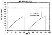
第1図: 蓄積効率を測定するための酸化窒素蓄積体の前及び後のNOx−濃度を示す図表。
【0061】
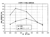
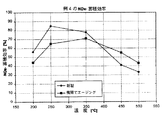
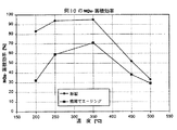
第2〜18図:排気温度に依存する若干の実施例及び比較例の蓄積触媒の酸化窒素−蓄積効率;各々新製及び機関でエージングされた触媒に関する。
【0062】
予備試験:
様々な担体物質を、空気中で850℃で24時間か焼させた際の、酸化窒素−蓄積成分とそれとの反応傾向に関して試験した。
【0063】
酸化窒素−蓄積成分として、酸化カリウム及び酸化バリウムを選択し、各々含浸によって担体物質上に析出させた。各担体物質100g上に、酸化バリウム20g又は酸化カリウム20gを被覆させた。
【0064】
か焼された蓄積物質を、レントゲン回析(XRD)により、各担体物質及び蓄積成分から成る複合酸化物の推定画像上で試験した。結果を第1表に挙げる。
【0065】
第1表は、試験した担体物質の名称と並んで、新製状態でのそのBET−表面積及びその組成を包含する。"複合酸化物"の欄には、生成可能な複合酸化物を挙げる。"最強反射"及び"2番目に強い反射"の欄には、生成可能な複合酸化物の双方の最も重要な反射に関する回折角を含有する。反射の強度を、各々の隣りの欄に、定性的に記載する。本発明の目的のためには、蓄積成分と僅かにのみ反応傾向を示す担体物質が好適である。このことは、反射が検知不可能であるか、又は"弱"から"中等"の強度を有する場合である。チタン酸バリウムは特別の場合であり、これは、既に自ら、酸化バリウム及び酸化チタンの間の複合酸化物であり、従って、か焼によって変化を経ない。
【0066】
第1表から明らかなように、慣用の担体物質である酸化ジルコン、酸化チタン、酸化アルミニウム及びマグネシウム/アルミニウム−スピネル(MgAl2O4)は、選択されたエージング条件下で、酸化バリウム及び酸化カリウムとの強い複合酸化物形成を示す。酸化マグネシウムは酸化バリウムとの複合酸化物を形成しない。酸化セリウムの場合には、理論的に可能なセリウム酸バリウム(BaCeO3)の形成は認めることができなかった。セリウム/ジルコン−複合酸化物は、酸化ジルコン含量が増加するにつれて、ジルコン酸バリウムの形成傾向を示す。しかし、複合酸化物形成は、セリウム/ジルコン−複合酸化物中の酸化ジルコン約30重量%の含量まで、なお許容可能である。珪酸ジルコンは、同様に蓄積成分との反応を示さない。
【0067】
本発明により、酸化窒素−蓄積成分用の好適な担体物質は、蓄積成分とのほんの僅少な複合酸化物生成傾向を示し、内燃機関の還元性及び酸化性排気条件に対するその比表面積の充分な安定性を有し、更に10m2/g以上の比表面積を有する。
【0068】
確かに、酸化セリウムは第1及び第3の条件を充分に満たすが、蓄積成分用の担体物質としてあまり好適ではなく、それは、その比表面積が、還元性排気条件下で(それは希薄運転オット機関の高負荷範囲で現われる)、僅かな安定性しか示さないからである。珪酸ジルコンの場合には、蓄積成分との複合酸化物形成は出現しないが、新製状態でのその比表面積は、高分散形での蓄積成分を充分な量を吸収するためには小さすぎる。このことは、使用される珪酸ジルコン変法に当てはまる。珪酸ジルコンのための特に説明された製法により、この物質をより大きな新製表面を有して製造することも可能であろう。この場合には、本発明による蓄積物質用の担体物質として同様に好適であろう。
【0069】
【表1】

NOx−蓄積触媒及びそのNOx−蓄積効率
次の実施例において、本発明による蓄積物質を使用して、様々な酸化窒素−蓄積触媒を製造し、その酸化窒素−蓄積効率を、本発明に依らない蓄積触媒と比較した。
【0071】
蓄積効率を、新製及びエージングされた触媒について調べた。触媒の製造の際に、若干の場合に、貴金属成分及び蓄積成分を、別々の担体粒子上に析出させ、そうして触媒組成物に組み入れた。他の場合には、貴金属及び蓄積成分を、同じ担体粒子上に析出させ、従って相互に直接接触させた。検査は、本発明による蓄積物質の利点が双方の場合に達成され、蓄積成分に対する貴金属の位置にはあまり依存しないことを示す。
【0072】
酸化窒素−蓄積触媒のエージングを、機関試験台で、行程容量2リットルを有する機関で、各々50時間をかけて行なった。触媒の入口の最高温度を750℃に調整した。各触媒での発熱反応に基づき、触媒床温度は、約830℃まで上昇した。エージングを、還元性排気条件下で、空気値λ=0.97で、周期的推力遮断で、120秒間毎に、各々5秒間行なった。推力遮断の間、空気値は、衝撃的に、0.97から明らかに1以上の値に変化した。
【0073】
触媒の酸化窒素−蓄積効率を、合成ガス装置で調べた。そのために、蓄積触媒をいわゆる濃厚/希薄−循環で運転し、その際、触媒を一定の温度で周期的に希薄、次いで濃厚な排気に曝した。希薄排気組成を、高酸素濃度の接続によって、同時の一酸化炭素及び水素の遮断で調整した。濃厚排気組成を、逆の工程法で生じさせた。
【0074】
希薄相内で、酸化窒素を、各々の触媒によって蓄積させた。濃厚相の間に、酸化窒素は触媒に接して離脱着及び排気の還元性成分、一酸化炭素、水素及び炭化水素の消費下に、窒素に変換した。
【0075】
図1は、この理想的な関係を示している。測定の間に、排気は、一酸化窒素(NO)の一定の濃度500vppm(容積ppm)を有する。それから、蓄積触媒中に入る酸化窒素濃度(NOx Ein)を、図1中に、破線で示した。蓄積触媒後の酸化窒素濃度(NOx AUS)は、最初はゼロである。それというのも、新製蓄積触媒は、理想的な場合には、排気中に含有される全ての酸化窒素を結合するからである。時間の経過に伴って、この蓄積触媒は酸化窒素を負荷し、その蓄積能力は減少する。それによって、蓄積触媒に結合される酸化窒素は次第に少なくなり、従って、触媒の後で、増加した酸化窒素濃度が測定可能になり、この濃度は、酸化窒素での蓄積触媒の完全な飽和の後には、初期濃度と同じになるはずである。従って、一定の時間後(図1では、80秒間後)に、蓄積触媒の再生を行なわなければならない。これは、約20秒間の排気の濃厚化によって行なわれる。それによって、蓄積された酸化窒素は脱着され、理想的な場合には、蓄積触媒の所で完全に変換され、従って、再生時間の間には、蓄積触媒の後の酸化窒素は測定不可能である。その後に、再び希薄排気に切り換えられ、酸化窒素の蓄積が新たに始められる。
【0076】
蓄積触媒の瞬間の蓄積効率は、次の比として定義される:
【0077】
【数1】
図1から明らかなように、この効率は時間に依存する。従って、蓄積触媒の評価のために、各蓄積相を経て集積され、連続した8つの蓄積サイクルを経て集められた蓄積効率Sを測定した:
【0079】
【数2】
従って、蓄積効率Sは物質定数ではなく、選択した濃厚/希薄−サイクルのパラメーターに依存している。製造された蓄積触媒の評価のために、次の条件を選択した:
濃厚/希薄−サイクルのパラメーター
空間速度: 50000h−1
温度範囲: 50℃の段階で150〜500℃
濃厚/希薄−サイクルの数: 温度段階毎に8
希薄相の持続時間: 80秒間
濃厚相の持続時間: 20秒間
【0081】
【表2】
図2〜18に、排気温度に依存する、様々な蓄積触媒についてのこの方法で調べた蓄積効率がプロットされている。
【0083】
【実施例】
例1:
この例において、酸化窒素−蓄積触媒の製造のために、先ず、本発明による酸化窒素−蓄積物質及び2種の触媒粉末を調製した。次いで、この3種の粉末物質を触媒に加工した。
【0084】
蓄積物質の製造のために、か焼された新製状態でBET−表面積87m2/gを有するセリウム/ジルコン−複合酸化物(酸化セリウム90重量%及び酸化ジルコン10重量%)550gを、酢酸バリウム水溶液での含浸、引き続く乾燥及び空気中で500℃でのか焼により、酸化バリウム100gで被覆した。か焼工程の時間は2時間であった。か焼により、可溶性の酢酸バリウムを、担体物質上に、酸化バリウム又は炭酸バリウムの形で固着させた。それによって、酢酸バリウムは次の製造工程で再び溶解しないことが保証された。
【0085】
形成された酸化バリウム粒子又は炭酸バリウム粒子の寸法は、それぞれ透過電子顕微鏡で調査した。平均粒径は1μmより小さかった。
【0086】
白金/酸化アルミニウム−粉末の調製のために、白金15gを、か焼された新製状態でBET−表面積210m2/gを有する酸化アルミニウム700g上に、白金テトラアミンニトレートの水溶液での含浸及び引き続く乾燥及び空気中で500℃でのか焼により析出させた。
【0087】
ロジウム/酸化アルミニウム−粉末の調製のために、ロジウム1.5gを、か焼された新製状態でBET−表面積142m2/gを有する酸化アルミニウム100g上に、硝酸ロジウム水溶液での含浸及び引き続く乾燥及び500℃でのか焼により析出させた。
【0088】
この方法で製造した3種の粉末を混合して水性分散液にし、磨砕して3〜5μmの粒径(d50)にした。分散液の酸化物の固体分を、浸漬法により市販のコージーライト製蜂巣構造体上に被覆した。
【0089】
この方法で被覆された蜂巣構造体を、乾燥箱中で120℃で乾燥させた。浸漬−及び乾燥−工程を、蜂巣構造体容積1リットル当たり、酸化物分230gの被覆が達成されるまで繰り返した。引き続き、被覆された蜂巣構造体を500℃で4時間か焼した。こうして、完成した触媒は、酸化バリウム15.9g/l、セリウム/ジルコン−複合酸化物87.2g/l、酸化アルミニウム126.9g/l、白金2.4g/l及びロジウム0.24g/lを含有した。
【0090】
比較例1:
触媒を、例1と同様にして調製したが、酸化バリウムを、例1で使用したセリウム/ジルコン−複合酸化物(CeO290重量%を有する)上ではなく、BET−表面積142m2/gを有するγ−酸化アルミニウム上に被覆させた。
【0091】
比較例2:
もう1種の触媒を、例1と同様にして調製したが、酸化バリウムを、例1で使用したセリウム/ジルコン−複合酸化物(CeO290重量%を有する)上ではなく、BET−表面積78m2/gを有する酸化チタン上に被覆させた。
【0092】
比較例3:
もう1種の触媒を、例1と同様にして調製したが、酸化バリウムを、例1で使用したセリウム/ジルコン−複合酸化物(CeO290重量%を有する)上ではなく、酸化ジルコン30重量%及びBET−表面積152m2/gを有するセリウム/ジルコン−複合酸化物上に被覆させた。
【0093】
比較例4:
もう1種の触媒を、例1と同様にして調製したが、酸化バリウムを、例1で使用したセリウム/ジルコン−複合酸化物(CeO290重量%を有する)上ではなく、BET−表面積184m2/gを有する純粋な酸化セリウム上に被覆させた。
【0094】
例2:
例1の触媒に、酢酸プラセオジム水溶液での含浸、乾燥及び引き続くか焼により、蜂巣構造体容積1リットル当たり、付加的に酸化プラセオジム15gを被覆させた。
【0095】
例3:
例1のもう1種の触媒に、硝酸ネオジム水溶液での含浸、乾燥及び引き続くか焼により、蜂巣構造体容積1リットル当たり、付加的に酸化ネオジム15gを被覆させた。
【0096】
例4:
例1で使用したセリウム/ジルコン−複合酸化物の代わりに、BET−表面積52m2/gを有する酸化マグネシウムを使用した。
【0097】
例5:
例4の触媒に、酢酸バリウム水溶液での含浸、乾燥及び引き続くか焼により、蜂巣構造体容積1リットル当たり、更に酸化バリウム8gを被覆させた。
【0098】
例6:
本発明による蓄積物質を、担体物質としての酸化マグネシウム及び蓄積成分としての酸化バリウムの共沈により、次の方法で得た:
MgCl2(13.8モル)及びBaCl2(0.65モル)から成る水溶液を、ビューレットから、アンモニア溶液9.8リットル中に滴下した。ここで、アンモニア溶液を強力に撹拌し、一定のpH値11.0及び温度60℃に保った。生じた沈殿を濾取し、脱ミネラル水中で洗浄し、空気中、120℃で乾燥させ、600℃で4時間か焼させた。
【0099】
こうして得られたBaO/MgO−粉末を、例1で製造した蓄積物質(セリウム/ジルコン−複合酸化物上の酸化バリウム)と同様の方法で、完全な触媒組成物に仕上げた。
【0100】
例7:
もう1種の本発明による蓄積物質を、担体物質としての酸化マグネシウム及び蓄積成分としての酸化バリウムの共沈により、次の方法で得た:
MgCl2(13.8モル)及びBaCl2(0.65モル)から成る水溶液を、ビューレットから、1.5モルの炭酸ナトリウム溶液9.8リットル中に滴下した。ここで、炭酸ナトリウム溶液を強力に撹拌し、60℃で一定の温度に保った。生じた沈殿を濾取し、脱ミネラル水中で洗浄し、空気中、120℃で乾燥させ、600℃で4時間か焼させた。
【0101】
こうして得られたBaO/MgO−粉末を、例1で製造した蓄積物質(セリウム/ジルコン−複合酸化物上の酸化バリウム)と同様の方法で、完全な触媒組成物に仕上げた。
【0102】
例8:
もう1種の本発明による蓄積物質を、担体物質としての酸化プラセオジム及び蓄積成分としての酸化バリウムの共沈により、次の方法で得た:
Pr(NO3)3(3.2モル)及びBa(NO3)2(0.65モル)から成る水溶液を、ビューレットから、0.5モルの(NH4)2C2O4−溶液19.2リットル中に滴下した。ここで、(NH4)2C2O4−溶液を強力に撹拌し、60℃で一定の温度に保った。アンモニア水溶液を同時に添加して、pH値を6.6に保った。生じた沈殿を濾取し、脱ミネラル水中で洗浄し、空気中、120℃で乾燥させ、600℃で4時間か焼させた。
【0103】
こうして得られたBaO/Pr6O11−粉末を、例1で製造した蓄積物質(セリウム/ジルコン−複合酸化物上の酸化バリウム)と同様の方法で、完全な触媒組成物に仕上げた。
【0104】
例9:
もう1種の本発明による蓄積物質を、担体物質としての酸化セリウム及び酸化プラセオジム及び蓄積成分としての酸化バリウムの共沈により、次の方法で得た:
Ce(NO3)4(2.8モル)、Pr(NO3)3(0.4モル)及びBa(NO3)2(0.65モル)から成る水溶液を、ビューレットから、0.5モルの(NH4)2C2O4−溶液19.2リットル中に滴下した。ここで、(NH4)2C2O4−溶液を強力に撹拌し、60℃で一定の温度に保った。アンモニア水溶液を同時に添加して、pH値を6.6に保った。沈殿を濾取し、脱ミネラル水中で洗浄し、空気中、120℃で乾燥させ、600℃で4時間か焼させた。
【0105】
こうして得られたBaO/CeOx/PrOy−粉末を、例1で製造した蓄積物質(セリウム/ジルコン−複合酸化物上の酸化バリウム)と同様の方法で、完全な触媒組成物に仕上げた。
【0106】
例10:
例1で使用したセリウム/ジルコン−複合酸化物の代わりに、酸化プラセオジム12重量%を用いる沈殿を介して安定化された酸化セリウムを使用した。安定化された酸化セリウムは、BET−表面積151m2/gを有した。
【0107】
例11:
例1で使用したセリウム/ジルコン−複合酸化物の代わりに、酸化ネオジム9重量%を用いる沈殿を介して安定化された酸化セリウムを使用した。安定化された酸化セリウムはBET−表面積162m2/gを有した。
【0108】
例12:
蓄積成分用の担体物質として、例10で製造され、酸化プラセオジムで安定化された酸化セリウムを使用した。例10と違って、安定化された酸化セリウムを、蓄積成分としての酸化バリウムではなく、同量の酸化ストロンチウムで含浸させた。
【0109】
例13:
例10からの完成触媒に、酢酸バリウム水溶液での含浸、乾燥及び引き続くか焼により、蜂巣構造体容積1リットル当たり、更に酸化バリウム8gを被覆した。
【0110】
例14:
例1で使用されたセリウム/ジルコン−複合酸化物の代わりに、酸化珪素1重量%で安定化された、BET−表面積219m2/gを有する酸化セリウムを使用した。
【0111】
例15:
先ず、NOx−蓄積物質を、例14におけるように製造した。しかし、付加的に更に酸化カルシウム6重量%を、硝酸カルシウム水溶液での後含浸、乾燥及びか焼により、酸化珪素で安定化された酸化セリウム上に被覆した。
【0112】
例16:
触媒を、例1からの量表示に相応して調製したが、製造は変更した。先ず、例1に記載の3種の粉末、つまり、Pt−酸化アルミニウム、Rh−酸化アルミニウム及び未処理のセリウム/ジルコン−複合酸化物(酸化セリウム90重量%及び酸化ジルコン10重量%)の分散液を製造した。分散液の磨砕後に、コージーライト製の蜂巣構造体にそれを被覆させた。被覆を空気中、300℃で乾燥させた後に、蜂巣構造体は、被覆濃度210g/蜂巣構造体lを有した。引き続いて、触媒に、酸化バリウム25gを、酢酸バリウム水溶液での含浸、乾燥及び空気中500℃で4時間のか焼により被覆した。
【0113】
この例で、蓄積成分である酸化バリウムの濃度は、全ての他の例に比べて、16g/lから25g/lに上昇させた。この例のために選択した製法に基づき、つまり、本発明により使用すべき担体物質、セリウム/ジルコン複合酸化物だけでなく、双方の触媒粉末(Pt−Al2O3及びRh−Al2O3)も酸化バリウムで被覆した。このための近似的均衡を取るために、蓄積触媒上の酸化バリウムの濃度を高めた。
【0114】
例17:
もう1種の触媒を例1に相応して調製した。しかし、例1と違って、蓄積物質を、酢酸バリウムでのセリウム/ジルコン−複合酸化物の含浸により製造するのではなく、炭酸アンモニウムとの沈殿反応により製造した。そのために、セリウム/ジルコン−複合酸化物(酸化セリウム90重量%及び酸化ジルコン10重量%)550gを、水700ml中に分散させ、酸化バリウム100gに相応する酢酸バリウム166gを添加した。絶えず撹拌しながら、水300ml中の炭酸アンモニウム63gから成る溶液を分散液に滴下した。それによって、バリウムは不溶性の炭酸バリウムの形で担体物質上に沈澱した。引き続き、分散液を、白金/酸化アルミニウム−粉末715g及びロジウム/酸化アルミニウム−粉末101.5gの添加後に、例1に記載したように更に加工し、即ち、磨砕し、被覆し、か焼した。
【0115】
この製法は、例1に記載した方法に比べて、酢酸バリウムから酸化バリウムへの変換のための蓄積物質のか焼が省略されるという利点を有する。バリウムは、沈殿によって炭酸バリウムとして担体物質上に直接固定される。
【0116】
例18:
もう1種の触媒を例17により製造した。この例では、沈殿試薬として、水1800ml中の蓚酸アンモニウム81gの水溶液を使用した。
【0117】
図1〜16の線図が示すように、比較例1〜4の触媒は、本発明による触媒と殆ど同じ新製活性を示す。特に200〜350℃でエージングの後に、比較触媒の蓄積効率は、本発明による触媒におけるよりも実際に強く低下する。エージングによる蓄積効率の減少は、比較触媒の場合には、大抵約40〜50%であり、一方、本発明による触媒における悪化は、ほんの10〜25%である。
【0118】
例19:
例1に記載されていると同様な方法でもう一つの触媒を製造した。但し、例1とは違って、ここでは、蓄積成分の担体物質を、酸化セリウム90重量%及び酸化プラセオジム10重量%より成る複合酸化物から選択した。この複合酸化物は、酸化セリウム及び酸化プラセオジム前駆物質の共沈により製造した。この担体物質は140m2/gの比表面積を有した。
【0119】
新製の及び排気温度以上で機関エージングされた触媒に関して、この蓄積物質の酸化窒素蓄積効率を図17に示す。
【0120】
比較例5:
例1に記載されていると同様な方法でもう一つの触媒を製造した。蓄積物質は、触媒ベース物質を得るためのドイツ特許(DE−A1)第19713432号明細書の記載に従って製造した。担体物質は100m2/gの比表面積を有する純粋な酸化セリウムから選択した。酢酸バリウムでの含浸の後にこの物質を乾燥させ、次いでドイツ特許(DE−A1)第19713432号明細書の例1に記載のように900℃で24時間か焼させた。
【0121】
新製の及び排気温度上で機関エージングされた触媒に関して、この蓄積物質の酸化窒素蓄積効率を図18に示す。
【0122】
図18は、ドイツ特許(DE−A1)第19713432号明細書による触媒ベース物質が、燃焼機関の排気中の前記エージング条件下で、低い温度安定性を有することを示している。新製蓄積物質は、本発明による蓄積物質のそれよりも既に低い250℃以下で蓄積効率を示している。250℃以上では、この蓄積効率は急速に低下する。
【0123】
より高温でのこの蓄積効率の急速な低下は、おそらく、900℃で2時間にわたるか焼の間に生じる大きい酸化バリウム粒子による。大きい粒子は明らかに蓄積プロセスの動的特性を悪化させる。250℃以上の温度では、二酸化窒素と一酸化窒素との間の平衡が一酸化窒素の方向に移動する。従って、良好な蓄積効率は、より高い温度では、触媒により発生される二酸化窒素が双方の酸化窒素の間の平衡から蓄積成分との反応により迅速に除去される場合にのみ得ることができる。しかしながら、大きい酸化バリウム粒子はこの仕事をすることはできない。
【図面の簡単な説明】
【図1】蓄積効率を測定するための酸化窒素蓄積体の前及び後のNOx−濃度を示すグラフ
【図2】例1の触媒の酸化窒素−蓄積効率を示すグラフ
【図3】比較例1の触媒の酸化窒素−蓄積効率を示すグラフ
【図4】比較例2の触媒の酸化窒素−蓄積効率を示すグラフ
【図5】比較例3の触媒の酸化窒素−蓄積効率を示すグラフ
【図6】比較例4の触媒の酸化窒素−蓄積効率を示すグラフ
【図7】例2の触媒の酸化窒素−蓄積効率を示すグラフ
【図8】例4の蓄積触媒の酸化窒素−蓄積効率を示すグラフ
【図9】例5の触媒の酸化窒素−蓄積効率を示すグラフ
【図10】例10の触媒の酸化窒素−蓄積効率を示すグラフ
【図11】例12の蓄積触媒の酸化窒素−蓄積効率を示すグラフ
【図12】例13の触媒の酸化窒素−蓄積効率を示すグラフ
【図13】例14の触媒の酸化窒素−蓄積効率を示すグラフ
【図14】例15の触媒の酸化窒素−蓄積効率を示すグラフ
【図15】例16の触媒の酸化窒素−蓄積効率を示すグラフ
【図16】例18の触媒の酸化窒素−蓄積効率を示すグラフ
【図17】例19の触媒の酸化窒素−蓄積効率を示すグラフ
【図18】比較例5の触媒の酸化窒素−蓄積効率を示すグラフ[0001]
BACKGROUND OF THE INVENTION
The present invention provides an alkaline earth metal on a support material.IsMagnesium, calcium, strontium and barium and alkali metalsIsThe present invention relates to a nitric oxide-accumulating substance containing at least one accumulating component of nitric oxide in the form of potassium, cesium oxide, carbonate or hydroxide.
[0002]
[Prior art]
In the field of gasoline engines, so-called lean engines have been developed that operate with lean air / fuel mixtures at part load operation, in order to reduce fuel consumption. The lean air / fuel mixture contains a higher oxygen concentration than is required for complete combustion of the fuel. At this time, oxidizing components, oxygen (O2), Nitric oxide (NOx) Are reducing exhaust components, carbon monoxide (CO), hydrogen (H2) And hydrocarbons (HC). Lean exhaust typically contains 3-15% oxygen by volume. However, within the range of load- and full-load operation, even a lean-run otto engine provides a stoichiometric or rather sub-stoichiometric, ie rich air / fuel preparation.
[0003]
In contrast, diesel engines work with a wide range of over stoichiometric air / fuel mixtures under all operating conditions.
[0004]
Due to the high oxygen content of the exhaust of lean or diesel engines, the nitrogen oxides contained therein are not like stoichiometrically operated Otto engines, but by so-called three-way catalysts, hydrocarbons and monoxide Under the simultaneous oxidation of carbon, it is reduced to nitrogen.
[0005]
Therefore, in order to remove nitrogen oxide from the exhaust gas, a nitrogen oxide-accumulating catalyst that accumulates nitrogen oxide contained in the lean exhaust gas in the form of nitrate has been developed.
[0006]
The operation of the nitric oxide-accumulating catalyst is described in detail in SAE 950809. According to it, the nitric oxide-accumulating catalyst consists mostly of an inert honeycomb structure made of ceramic or metal, the so-called support material in the form of a coating on a support. This catalytic material contains a nitric oxide-accumulating material and a catalytically active component. Further, the nitric oxide-accumulating substance is composed of a specific nitric oxide-accumulating component deposited in a highly dispersed form on the carrier substance.
[0007]
As storage components, basic oxides of alkali metals, alkaline earth metals and rare earth metals, in particular barium oxide, are used, which react with nitrogen dioxide to the corresponding nitrates. These substances are known to exist mostly in the form of carbonates and hydroxides in air. These compounds are likewise suitable for the accumulation of nitric oxide. Accordingly, within the scope of the present invention, when discussing basic storage oxides, the corresponding carbonates and hydroxides are also included.
[0008]
As the catalytically active component, platinum group rare metals are typically used, which are typically deposited on the support material together with the accumulating component. As the support material, active high surface area aluminum oxide is mainly used.
[0009]
The problem with catalytically active components is to convert carbon monoxide and hydrocarbons in lean exhaust into carbon dioxide and water. Furthermore, it should be able to oxidize the nitric oxide component of the exhaust to nitrogen dioxide and thus react with basic accumulating substances to nitrate. The more nitric oxide accumulates in the accumulating material, the less this material accumulates and therefore must be regenerated from time to time. For this purpose, the engine is operated for a short time with a stoichiometric or rich air / fuel mixture. Under reduced conditions in rich exhaust, the formed nitrate is converted to NOxAnd reduced to nitrogen under the formation of water and carbon dioxide using carbon monoxide, hydrogen and hydrocarbons as reducing agents. This storage catalyst acts as a three-way catalyst during this operating phase.
[0010]
An important problem with stored materials is their poor aging stability at high temperatures.
As shown in SAE Technical Paper 970746, an important aging mechanism for nitric oxide-accumulating materials is that the original accumulating components react with the support material. That is, in a storage material consisting of barium oxide on zircon oxide aged at 750 ° C. for 24 hours, barium zirconate BaZrO3Production was observed. Barium oxide on titanium oxide was formed by barium titanate. In both cases, this reaction between the accumulating component and the carrier material was associated with a high loss of nitric oxide-accumulating capacity. Thus, zircon oxide and titanium oxide, due to their high tendency to react with barium oxide, for alkali metal- and alkaline earth metal-accumulating components when they are exposed to high temperature loads in use. It is not suitable as a carrier. Aluminum oxide reacts somewhat favorably as a support material. However, also in this case, barium aluminate is formed during aging at a high temperature for a longer time.
[0011]
In the patent literature various combinations of accumulating components and carrier materials are known which also solve the aging problem. For example, EP-A1 0562516 describes a catalyst consisting of barium oxide, lanthanum oxide and platinum on a support material consisting of aluminum oxide, zeolite, zircon oxide, aluminum silicate or silicon dioxide. In this case, at least a part of barium oxide and lanthanum oxide iscompositeAn oxide is formed. thiscompositeOxide suppresses the formation of lanthanum aluminate, but otherwise results in aging of the catalyst.
[0012]
In order to suppress the reaction between the accumulating component and the support made of aluminum oxide, European Patent (EP-A2) 0 645 173 describes that lithium is dissolved in the support so that a solid solution consisting of aluminum oxide and lithium is formed. Propose to let you.
[0013]
European Patent (EP-A1) 0653238 proposes titanium oxide containing at least one element from the group of alkali metals, alkaline earth metals and rare earth metals in the form of a solid solution as a support material. Yes.
[0014]
European Patent (EP-A1) 0657204 is used as a support material for a nitric oxide-accumulating catalyst.compositeOxide, TiO2-Al2O3, ZrO2-Al2O3And SiO2-Al2O3Cite. In addition, TiO2, Al2O3With alkaline earth and rare earth metalscompositeOxides, especially TiO2-Al2O3-Sc2O3TiO2-Al2O3-Y2O3TiO2-Al2O3-La2O3And TiO2-Al2O3-Nd2O3Are mentioned as carrier materials.
[0015]
EP-A1 0666103 describes a catalyst containing a nitric oxide-accumulating component and a noble metal on a porous support material. As support materials, aluminum oxide, zeolite, zircon oxide, aluminum silicate and silicon dioxide have been proposed. Nitric oxide-accumulating components and noble metals are deposited intimately on the support particles. Furthermore, the catalyst can also contain cerium oxide as an oxygen storage component, wherein the cerium oxide is retained separately from the noble metal and hence from the storage component.
[0016]
European Patent (EP-A1) 0718028 discloses a heat-resistant nitric oxide-accumulating substance. High heat resistance is obtained by very finely dispersing the nitric oxide-accumulating component in the support material. For this purpose, a solution of at least one alkali metal, alkaline earth metal and rare earth metal compound is mixed with a solution of at least one oxide sol of a group IIIb, IVa and IVb group metal into a gel. Transfer, dry, and calcinate. The resulting accumulated material is amorphous. In this example, the accumulating material is used in particular for high surface area cerium / zirconcompositeCombine with catalyst powder with platinum on oxide. In this case, in short, cerium / zirconcompositeThe oxide forms the support material for the platinum component.
[0017]
European Patent (EP-A1) No. 0771584 is likewise amorphous.compositeA refractory support material for the catalyst, consisting of oxides, is described. This amorphouscompositeThe oxide has a composition from a nitric oxide-accumulating component from the group of alkali metals, alkaline earth metals and rare earth metals, and at least one oxide from the group of aluminum oxide and titanium oxide, zircon oxide and silicon dioxide. . Aluminum oxide is amorphouscompositeIt is an important component of the oxide and has a molar ratio of 4 to 12 with respect to the accumulated component. Still further, the carrier material may contain cerium oxide as the storage material oxygen. The cerium oxide and nitric oxide-accumulating components may be present only in a molar ratio of 0.5 to 3 in the support material. According to the description in European Patent (EP-A1) No. 0775884, heat resistance deteriorates outside this range.
[0018]
World Intellectual Property Organization (WO) No. 97/02886 describes a nitric oxide-accumulating catalyst in which the accumulating component and the catalytically active component are spatially separated from each other but are arranged adjacent to each other. is doing. For this purpose, the accumulating component and the catalyst component are applied on the support in two layers that overlap each other. For this purpose, the storage component and the catalyst component can optionally be deposited on different support particles, which are then placed together on the support in the form of a coating. Accumulated materials include metal oxides, metal hydroxides, metal carbonates and metalscompositeOxides are described. The metal may be lithium, sodium, potassium, rubidium, cesium, magnesium, calcium, strontium or barium.
[0019]
According to World Intellectual Property Organization (WO) No. 97/02886, the accumulating material can contain sulfur-absorbing components, preferably cerium oxide, for protection against sulfur poisoning. The cerium oxide may be present in the form of particles alongside the accumulating material particles or dispersed in the nitric oxide-accumulating component.
[0020]
None of the proposed solutions produce a nitric oxide-accumulating material with sufficient aging stability. Rather, in all known accumulating materials, at high temperatures (> = 700 ° C.), the irreversible reaction with the support material to the corresponding aluminates, zirconates, silicates, titanates, etc., reduces the nitric oxide. Deactivation of the accumulated alkali metal and alkaline earth metal oxides occurs. Subsequently, alkali metal- and alkaline earth metal oxides can no longer accumulate nitric oxide due to the loss of basicity caused thereby. The accumulating component is generally present in a molar excess compared to the carrier oxide, so that depending on the time, exhaust composition and exhaust temperature, the accumulating component reacts completely with the carrier oxide.compositeAn oxide can be produced.
[0021]
German Patent (DE-A1) No. 1971432 describes impregnating cerium oxide with a solution containing barium and calcining the cerium oxide particles at a temperature of 400 to 1100 ° C. to oxidize on the surface of the cerium oxide particles. A catalyst base material for obtaining an exhaust purification catalyst obtained by forming barium is described. According to this document, a mixture of barium oxide and cerium oxide particles is calcined at a relatively high temperature to form coarse barium oxide particles on the surface of the cerium oxide particles.
For this purpose, temperatures between 800 and 1100 ° C. are very effective. It is advantageous to calcine the cerium oxide particles at 900 ° C. for 24 hours. This produces barium oxide particles having a particle size of 7-14 μm. At a calcination temperature of 200 ° C., the average particle size is still 1.9 μm.
[0022]
The catalyst base material according to DE-A1 19713432 is used for the production of a catalyst which is particularly effective for the purification of lean burn engine exhaust. Therefore, this catalyst is a so-called lean-NO that can reduce nitrogen oxide in lean exhaust gas to nitrogen on the assumption that the exhaust gas contains a sufficient amount of reducing exhaust components (carbon monoxide and hydrogen).x-A catalyst. This catalyst base material is said to increase the temperature stability of the catalyst. German patent (DE-A1) No. 19713432 makes no mention of the ability of this catalyst base material to accumulate nitric oxide.
[0023]
[Problems to be solved by the invention]
The object of the present invention is to provide a nitric oxide-accumulating material characterized in that it has a high accumulation efficiency at the same time with practically improved aging stability. A further object of the present invention is to provide a process for the production of this accumulating material and a nitric oxide-accumulating catalyst on the inert carrier produced by the accumulating material, a combination of accumulating material and platinum group noble metal, The present invention relates to the use of nitric oxide-accumulators and accumulating catalysts for the treatment of exhaust gas from lean operating internal combustion engines.
[0024]
[Means for Solving the Problems]
The challenge is to use alkaline earth metals on the support material.IsMagnesium, calcium, strontium and barium and alkali metalsIsIt is solved by a nitric oxide-accumulating material containing at least one accumulating component of nitric oxide in the form of particles of potassium and cesium oxides, carbonates or hydroxides. This nitric oxide-accumulating material is a carrier material doped with cerium oxide, cerium / zirconcompositeOxides, calcium titanate, strontium titanate, barium titanate, barium stannate, barium zirconate, magnesium oxide, lanthanum oxide, praseodymium oxide, samarium oxide, neodymium oxide, yttrium oxide, barium yttrium cuprate, lead titanate, Selected from the group of tin titanate, bismuth titanate, lanthanum cobaltate, lanthanum manganate and barium cuprate or mixtures thereof, the particles of this nitric oxide accumulating component have an average particle size of 1.5 μm or less It is characterized by.
[0025]
The carrier materials to be used can be divided into 4 groups. The first group belongs to support materials based on cerium oxide. Doped cerium oxide and cerium / zirconcompositeOxides are important. Regardless of the method of manufacture, these materials have a broad crystal structure and are therefore not amorphous. The second group includes a stoichiometric composition consisting of an oxide of a storage component and a carrier oxide.compositeThere is an oxide. Examples of barium oxide and titanium oxidecompositeAn example of the oxide is barium titanate. That is, this group includes calcium titanate, strontium titanate, barium titanate, barium stannate and barium zirconate. The third group includes the pure oxides magnesium oxide, lanthanum oxide, praseodymium oxide, samarium oxide, neodymium oxide and yttrium oxide. The fourth group has othercompositeThe oxides include barium yttrium cuprate, lead titanate, tin titanate, bismuth titanate, lanthanum cobaltate, lanthanum manganate and barium cuprate.
[0026]
The carrier material for the accumulating component used exhibits a slight or no tendency to react with the accumulating component, and at the same time is stable against lean engine lean and rich alternating exhaust compositions. It has been found that active and aging stable accumulating materials can be obtained if the specific surface area of the support material is sufficiently stable under the actual exhaust conditions of the lean engine.
[0027]
The theoretical storage capacity of the storage material is derived from the molar amount of storage component coated with the support material. This maximum storage capacity can be better utilized as the storage component precipitates more finely on the support material. Therefore, it is recommended to select a support material that has a higher specific surface area on which the accumulated components can precipitate in a higher dispersion.
[0028]
For use as a nitric oxide-accumulating substance, a loading of the carrier substance with an accumulating component of 10 to 45, preferably 20 to 30% by weight, based on the total weight of the accumulating substance is desired. Thus, the carrier material is 10 or more, preferably 50 m, depending on the load.2Should have a specific surface area (measured according to DIN 66132) of at least / g. The total pore volume consisting of mesopores (pore diameter d = 2-30 nm) and macropores (pore diameter d:> 30 nm) should be at least 0.1, preferably 0.3 ml / g.
[0029]
As confirmed by examination by X-ray diffraction, the carrier material shows only a slight reaction tendency with the accumulated components. 10m2Having a specific surface area of at least / g, which also has sufficient stability under lean engine exhaust conditions. This is particularly true for doped cerium oxide, cerium / zirconcompositeThis applies to oxides and magnesium oxide.
[0030]
The size of the new surface area of these materials depends on the method of manufacturing the material, the thermal pretreatment and optionally doping with other elements. For example, from the thermal decomposition of magnesium carbonate, resulting in 100m2High surface area magnesium oxide having a surface area greater than / g or 2 m2It can also be obtained as a sintered material having a surface area less than / g. This sintered material is unsuitable for the purposes of the present invention.
[0031]
Pure cerium oxide is 100m2/ G or higher. This material remains 10 m after calcination in air at 900 ° C. for 10 hours.2/ G or more specific surface area. In contrast, calcination under reducing conditions at high temperatures, as typically occurs in high load operation of all conventional otto and lean engines, is 10 m.2/ G or less specific surface area. Thus, pure cerium oxide is not well suited as a carrier material for the accumulating component.
[0032]
The specific surface area of cerium oxide is an element from the group comprising silicon, scandium, yttrium and rare earth metals (lanthanum, praseodymium, neodymium, promethium, samarium, europium, gadolinium, terbium, dysprosium, holmium, erbium, thulium, ytterbium and lutetium) It is also possible to stabilize against reducing exhaust conditions by doping with the oxides or mixtures of these oxides. To that end, 0.5 to 20, preferably 5 to 10% by weight of the respective oxide or oxide mixture is required. In this case, the concentration indication relates to the total weight of the carrier material. Doping can be carried out in a manner known per se, for example by coprecipitation, co-thermal hydrolysis, impregnation and precipitation.
[0033]
That is, doped cerium oxide can be obtained by coprecipitation from an aqueous solution of cerium oxide and a precursor compound of the doping oxide. For example, praseodymium-doped cerium oxide is prepared by adding ammonium carbonate or ammonium oxalate to an aqueous solution from cerium nitrate and praseodymium nitrate and precipitating cerium and praseodymium together as carbonate or oxalate. Can do. After filtration and drying, the precipitate is converted into the corresponding oxide by calcination. Optionally, the coprecipitation can also be performed in a basic medium.
[0034]
During the co-thermal hydrolysis, water is removed from the sol consisting of cerium hydroxynitrate and the hydroxy nitrate of the doping element by supplying heat. Thereby, the hydroxy nitrate is decomposed into the corresponding oxide. Co-thermal hydrolysis is described, for example, in World Intellectual Property Organization (WO) 98/16472.
[0035]
For doping of cerium oxide by impregnation, cerium oxide present as a powder substance is immersed in an aqueous solution of the desired doping oxide precursor compound. At this time, so-called pore volume impregnation, in which a precursor compound of a doping oxide is dissolved in a volume of water corresponding to the water absorption capacity of the cerium oxide powder, is often used.
[0036]
In doping cerium oxide by precipitation, cerium oxide present as a powder substance is dispersed in an aqueous solution of a precursor compound of a doping element. By slowly adding the base, the accumulating components are precipitated on the support material in the form of hydroxides.
[0037]
Of the methods described, the coprecipitation method and the co-thermal hydrolysis method are most advantageous. These are very uniformly doped over the entire cross section of the cerium oxide particles.
[0038]
In all four methods, the precursor compound or its sparingly soluble precipitate is converted to the corresponding oxide by calcination at temperatures up to 800 ° C.
[0039]
Also suitable carrier materials for the storage component are cerium / zirconcompositeAlthough an oxide, zircon oxide cannot be used as the sole support material because it reacts with, for example, barium oxide to barium zirconate. But with cerium oxide as an ingredientcompositeIn the presence of oxide, this reaction is significantly reduced because cerium oxide shields the zircon oxide and thus sufficiently prevents the reaction between zircon oxide and barium oxide.
[0040]
Cerium / ZirconcompositeOxides are obtained commercially in a wide range of mixing ratios of cerium oxide to zircon oxide and, as with pure cerium oxide, are widespread as oxygen-accumulating materials in conventional three-way catalysts. Cerium / ZirconcompositeThe production of oxides can be carried out, for example, via mechanical mixing or impregnation and coprecipitation methods. Within the scope of the present invention, the excellent properties of this material as a carrier material for the storage component are important. Its oxygen storage capacity is not very important.
[0041]
Cerium / ZirconcompositeThe oxidecompositeAgainst the total weight of the oxidecompositeIf the oxide zircon oxide content does not exceed 25, preferably 20% by weight, it has particularly advantageous properties as a carrier material for the storage component. However, in order to give the cerium oxide sufficient stability against reducing exhaust conditions, the zircon oxide content of the oxidation mixture should not fall below 1% by weight. Zircon oxide 5 to 15% by weight is particularly advantageous. Very good results could be achieved with a 10% by weight content of zircon oxide. Above 25% by weight of zircon oxide, cerium oxide can no longer shield zircon oxide with accumulated components prior to reaction at high temperatures. Thus, cerium / zircon having 30% by weight of zircon oxidecompositeOxides are no longer suitable as carrier materials for stored components under high exhaust temperature operating conditions.
[0042]
In the state of the art cited at the outset, rare earth metal oxides are often also indicated as nitric oxide-accumulating components. However, in the accumulating material according to the present invention, the cerium oxide used has been found to have, in some cases, a small portion of the accumulating capacity of accumulating components, so the rating of cerium oxide as a carrier material within the scope of the present invention is proved. Has been. This is also true considering the fact that in the accumulating material according to the invention the carrier material is present in a high molar excess relative to the accumulating component.
[0043]
A molar ratio of carrier material to accumulating component of 2: 1 to 25: 1 can be used. Molar ratios greater than 25: 1 are not recommended, because in that case the storage capacity of the storage material is too small for technical applications. In contrast, below a 2: 1 ratio, the accumulating material can no longer be deposited on the support material in a sufficiently highly dispersed form. Therefore, it is advantageous to use a molar ratio of 3.5: 1 to 6: 1.
[0044]
Cerium / ZirconcompositeAnother improvement in the surface heat resistance of the oxide is that, as in pure cerium oxide, silicon, scandium, yttrium and rare earth metals (lanthanum, cerium, praseodymium, neodymium, promethium, samarium, europium, gadolinium, terbium, dysprosium, (Holidium, erbium, thulium, ytterbium and lutetium). This can be achieved by doping with an oxide of an element from the group comprising or a mixture of these oxides. To that end, 0.5 to 20, preferably 5 to 10% by weight of the respective oxide or oxide mixture is required. In this case, the concentration indication relates to the total weight of the carrier material. The doping can be performed by the method already described in the case of cerium oxide doping.
[0045]
Support materials based on cerium oxide are particularly advantageous for the production of accumulating materials to be used in exhausts containing sulfur dioxide. Sulfur dioxide reacts with barium oxide competitively with nitrogen dioxide after oxidation to sulfur trioxide to yield barium sulfate. Since barium sulfate is actually more thermally stable than barium nitrate, it continuously reduces the storage capacity of stored materials. Therefore, the accumulating material must sometimes be desulfated. For this purpose, the engine is operated with a sub-stoichiometric air / fuel-mixture (λ <0.98) and the exhaust temperature is increased. In order to desulfate barium oxide on the conventional accumulating material, aluminum oxide, a temperature of 650 ° C. or higher is required. By the way, it has been found that cerium oxide is used as a carrier material for barium oxide, and therefore clearly exerts a promoting action on desulfation of barium oxide when directly contacted with the generated barium sulfate. Barium oxide (BaO / CeO on cerium oxide, the storage material according to the invention)2) Desulfation already begins at only 550 ° C. This is particularly advantageous because of the fuel savings associated with it.
[0046]
For the production of the storage material of the present invention, the storage component must be placed or loaded on the carrier material in an appropriate manner. In this case, it is possible to use the techniques of coprecipitation, co-thermal hydrolysis, impregnation and precipitation already described for the doping of cerium oxide. Production is advantageously carried out by impregnating the support material with a soluble precursor of the storage component, followed by drying and calcination at 300-800 ° C., wherein the precursor is converted into a unique oxidative storage component. After cooling to room temperature, the accumulating component reacts with the carbon dioxide and water content of the air, so that, as already mentioned, a certain portion of the accumulating component is also present as carbonate or hydroxide.
[0047]
According to the present invention, a selected pair of carrier material / accumulation components iscompositeNote that it has no tendency to form oxides. This is also true for coprecipitation and co-thermal hydrolysis. In these two cases,compositeThe lack of ability to form oxides results in the formation of regions composed primarily of support material and regions composed primarily of accumulating components.
[0048]
Calcination of the impregnated support material is an important step in the production of this storage material. The manner of calcination substantially affects the dimensions of the particles and the regions that form barium oxide or barium carbonate particles. In order to provide a sufficiently large surface area for contact between the stored components and the exhaust, this particle size should be 1.5 μm or less, preferably 1 μm or less. Since these reactive components should only diffuse over a small distance within the particles of the accumulating component, the small particle size also improves the dynamic properties of nitric oxide and sulfur oxide accumulation and desorption. Therefore, the accumulation of nitric oxide in small accumulating particles can cope with fluctuating exhaust compositions based on rapid conversion of engine load.
[0049]
In order to limit the particle size of the accumulating component to values below 1-1.5 μm, the calcination temperature and time should be selected appropriately. A particle size of 1 μm or less can be obtained using a calcination temperature of 500 ° C. for 2 hours. The particle size of the accumulated particles can be checked using a transmission electron microscope or by evaluating the width of a diffraction peak of X-ray diffraction analysis.
[0050]
As the precursor or precursor compound of the accumulating component, a water-soluble compound such as acetate, nitrate, nitrite, chloride, hydroxide or the like is used. Acetate has proven to be advantageous because it promotes the formation of small particles of accumulated components.
[0051]
A doping element for stabilizing the support material is added to the impregnating solution containing the precursor of the storage component in the form of a soluble precursor, so that doping with the doping element and coating with the storage component are carried out in one working step. be able to.
[0052]
The accumulation component can be precipitated by a method in which a solution of the water-soluble compound of the accumulation component is added to the carrier material, and this is precipitated on the carrier material by adding a precipitation reagent.
Suitable precipitation reagents for strontium and barium anions are present in the form of ammonium carbonate and ammonium oxalate.
[0053]
The accumulating material can be used for the preparation of nitric oxide-accumulators. In this case, an inert honeycomb structure made of metal or ceramic in which the flow groove is covered with a storage material is important. For coating, the powdered accumulating material is processed into an aqueous coating dispersion, applied onto the honeycomb structure by known coating methods, dried and calcined.
[0054]
In the production of such nitric oxide accumulators, the accumulating material is produced “in situ”, i.e. untreated carrier material can also be used for the preparation of the aqueous coating dispersion. To this coating dispersion, the accumulating and stabilizing components are added in the form of their soluble precursors. The coating dispersion is then used to coat the honeycomb structure, the coating is dried and finally calcined. That is, at this time, the accumulation substance is generated for the first time during the coating on the honeycomb structure. This process saves the calcination step.
[0055]
Alternatively, a coating dispersion containing only the carrier material can be prepared. Using this dispersion, the honeycomb structure is coated, dried and calcined. Subsequently, the coated honeycomb structure is coated by impregnation with accumulating components and optionally a soluble precursor of the doping element, dried and calcined. Again, the accumulating material first occurs in the coating of the honeycomb structure. Any combination of the above recipes can be considered.
[0056]
The accumulating substances according to the invention can be combined particularly advantageously with conventional accumulating substances. That is, for example, when the accumulating substance is mixed with a substance containing an accumulating component on a known carrier substance, for example, barium oxide on γ-aluminum oxide (active aluminum oxide), the thermal stability of the nitric oxide accumulator is improved. Significant improvements are already obtained. The “in situ” -preparation method described above can also be applied to accumulating materials so mixed in any combination.
[0057]
The accumulating material according to the invention can be advantageously processed into a nitric oxide-accumulating catalyst consisting of an inert honeycomb structure whose flow grooves are coated with a catalytic material. The catalytic material comprises a storage material and a catalytically active metal component. The catalytically active component can be present on the storage material itself or on another support material, preferably aluminum oxide. For this purpose, it is advantageous to use stabilized aluminum oxide. Often doped with lanthanum or barium for the stabilization of aluminum oxide. Such materials are obtained commercially.
[0058]
Various “in-situ” -techniques can be used in the production of the nitric oxide-accumulating catalyst, where the accumulating material only occurs during the final calcination of the coated honeycomb structure.
[0059]
Some of the described preparation methods are presented for the following examples and comparative examples.
[0060]
Each figure shows the following:
Fig. 1: NO before and after the nitric oxide accumulator to measure the accumulation efficiencyx-Chart showing concentration.
[0061]
FIGS. 2-18: Nitrogen oxide-accumulation efficiency of some example and comparative example accumulation catalysts depending on exhaust temperature; relating to new and engine-aged catalysts, respectively.
[0062]
Preliminary test:
Various carrier materials were tested for their tendency to react with nitric oxide-accumulating components when calcined in air at 850 ° C. for 24 hours.
[0063]
Potassium oxide and barium oxide were selected as nitric oxide-accumulating components, each deposited on a support material by impregnation. 100 g of each carrier material was coated with 20 g of barium oxide or 20 g of potassium oxide.
[0064]
The calcined accumulating material is composed of each carrier material and accumulating component by X-ray diffraction (XRD).compositeTested on an estimated image of the oxide. The results are listed in Table 1.
[0065]
Table 1 includes the BET-surface area and its composition in the fresh state, along with the names of the carrier materials tested. "compositeIn the "Oxide" column, it can be generatedcompositeList oxides. In the "Highest reflection" and "Second strongest reflection" columns, you can createcompositeContains diffraction angles for the most important reflections of both oxides. The intensity of reflection is qualitatively described in each adjacent column. For the purposes of the present invention, support materials that exhibit a slight tendency to react with the accumulating components are preferred. This is the case when the reflection is undetectable or has a “weak” to “moderate” intensity. Barium titanate is a special case, which is already between itself and barium oxide and titanium oxide.compositeIt is an oxide and is therefore not changed by calcination.
[0066]
As is apparent from Table 1, the conventional carrier materials zircon oxide, titanium oxide, aluminum oxide and magnesium / aluminum-spinel (MgAl2O4) Strong with barium oxide and potassium oxide under selected aging
[0067]
In accordance with the present invention, a suitable carrier material for the nitric oxide-accumulating component is only a fraction of the accumulating component.compositeIt has a tendency to form oxides, has sufficient stability of its specific surface area against reducing and oxidizing exhaust conditions of internal combustion engines, and further 10m2/ G or more specific surface area.
[0068]
Certainly, cerium oxide fulfills the first and third conditions well, but is not well suited as a carrier material for storage components, because it has a specific surface area under reducing exhaust conditions (it is a lean operating otto engine). This is because it shows only a slight stability. In the case of zircon silicate,compositeOxide formation does not appear, but its specific surface area in the new state is too small to absorb a sufficient amount of accumulated components in the highly dispersed form. This applies to the zircon silicate variant used. It would also be possible to produce this material with a larger new surface by a specifically described process for zircon silicate. In this case, it will be equally suitable as a carrier material for the storage material according to the invention.
[0069]
[Table 1]
NOx-Accumulated catalyst and its NOx-Storage efficiency
In the following examples, the storage material according to the present invention was used to produce various nitric oxide-storage catalysts, and the nitrogen oxide-storage efficiency was compared with storage catalysts not according to the present invention.
[0071]
The storage efficiency was investigated for the new and aged catalyst. During the manufacture of the catalyst, in some cases, the noble metal component and the accumulating component were deposited on separate support particles and thus incorporated into the catalyst composition. In other cases, the noble metal and the accumulating component were deposited on the same carrier particles and thus in direct contact with each other. The examination shows that the advantages of the accumulating material according to the invention are achieved in both cases and are less dependent on the position of the noble metal relative to the accumulating component.
[0072]
The aging of the nitric oxide-accumulating catalyst was carried out on an engine test bench in an engine having a stroke capacity of 2 liters over 50 hours each. The maximum temperature of the catalyst inlet was adjusted to 750 ° C. Based on the exothermic reaction at each catalyst, the catalyst bed temperature rose to about 830 ° C. Aging was performed under reducing exhaust conditions with an air value of λ = 0.97 and periodic thrust shut-off every 120 seconds for 5 seconds each. During the thrust block, the air value shockedly changed from 0.97 to a value of 1 or more.
[0073]
The nitrogen oxide-accumulation efficiency of the catalyst was investigated with a synthesis gas apparatus. For this purpose, the storage catalyst was operated in a so-called rich / lean-circulation, in which the catalyst was periodically exposed to a lean, then rich exhaust at a constant temperature. The lean exhaust composition was tuned with simultaneous carbon monoxide and hydrogen shut-off by high oxygen concentration connections. A rich exhaust composition was produced in the reverse process.
[0074]
Within the dilute phase, nitric oxide was accumulated by each catalyst. During the rich phase, nitric oxide was contacted with the catalyst and converted to nitrogen with consumption of desorbing and exhausting reducing components, carbon monoxide, hydrogen and hydrocarbons.
[0075]
FIG. 1 shows this ideal relationship. During the measurement, the exhaust has a constant concentration of nitric oxide (NO) of 500 vppm (volume ppm). Then, the concentration of nitric oxide (NO) entering the storage catalystx Ein) is indicated by a broken line in FIG. Nitrogen oxide concentration after storage catalyst (NOx AUS) is initially zero. This is because the new storage catalyst, in the ideal case, combines all the nitric oxide contained in the exhaust. Over time, this storage catalyst is loaded with nitric oxide and its storage capacity decreases. Thereby, less nitric oxide is bound to the accumulating catalyst, so that after the catalyst, an increased nitric oxide concentration becomes measurable, this concentration after complete saturation of the accumulating catalyst with nitric oxide. Should be the same as the initial concentration. Therefore, the accumulated catalyst must be regenerated after a certain time (after 80 seconds in FIG. 1). This is done by enriching the exhaust for about 20 seconds. Thereby, the accumulated nitric oxide is desorbed and, in the ideal case, completely converted at the accumulating catalyst, so that during the regeneration time no nitric oxide after the accumulating catalyst is measurable. is there. Thereafter, the exhaust gas is switched to lean exhaust again, and accumulation of nitric oxide is newly started.
[0076]
The instantaneous storage efficiency of the storage catalyst is defined as the ratio:
[0077]
[Expression 1]
As is apparent from FIG. 1, this efficiency is time dependent. Therefore, for the evaluation of the storage catalyst, the storage efficiency S collected through each storage phase and collected through 8 consecutive storage cycles was measured:
[0079]
[Expression 2]
Thus, the storage efficiency S is not a material constant, but depends on the selected rich / dilute-cycle parameters. The following conditions were selected for evaluation of the produced storage catalyst:
Rich / dilute-cycle parameters
Space velocity: 50000h-1
Temperature range: 150-500 ° C at 50 ° C stage
Rich / Dilute-Number of cycles: 8 per temperature step
Dilute phase duration: 80 seconds
Rich phase duration: 20 seconds
[0081]
[Table 2]
Figures 2-18 plot the storage efficiencies investigated in this way for various storage catalysts depending on the exhaust temperature.
[0083]
【Example】
Example 1:
In this example, a nitric oxide-accumulating material and two catalyst powders according to the present invention were first prepared for the production of a nitric oxide-accumulating catalyst. The three powder materials were then processed into catalysts.
[0084]
BET-surface area 87m in the newly calcined state for the production of accumulated substances2Cerium / zircon with / gcomposite550 g of oxide (90% by weight of cerium oxide and 10% by weight of zircon oxide) was coated with 100 g of barium oxide by impregnation with an aqueous barium acetate solution, subsequent drying and calcination at 500 ° C. in air. The time for the calcination process was 2 hours. By calcination, soluble barium acetate was fixed on the support material in the form of barium oxide or barium carbonate. This ensured that the barium acetate did not dissolve again in the next manufacturing step.
[0085]
The size of the formed barium oxide particles or barium carbonate particles was examined with a transmission electron microscope. The average particle size was less than 1 μm.
[0086]
For the preparation of platinum / aluminum oxide powder, 15 g of platinum was calcined in a freshly prepared state with a BET surface area of 210 m.2It was deposited on 700 g of aluminum oxide having a / g by impregnation with an aqueous solution of platinum tetraamine nitrate and subsequent drying and calcination in air at 500 ° C.
[0087]
For the preparation of rhodium / aluminum oxide-powder, 1.5 g of rhodium in a freshly calcined state BET-surface area 142 m2It was deposited on 100 g of aluminum oxide having a / g by impregnation with an aqueous rhodium nitrate solution and subsequent drying and calcination at 500 ° C.
[0088]
The three powders produced in this way are mixed into an aqueous dispersion and ground to a particle size of 3-5 μm (d50) The oxide solid content of the dispersion was coated on a commercially available cordierite honeycomb structure by dipping.
[0089]
The honeycomb structure coated by this method was dried at 120 ° C. in a drying box. The soaking and drying steps were repeated until a coating of 230 g oxide per liter of honeycomb structure volume was achieved. Subsequently, the coated honeycomb structure was calcined at 500 ° C. for 4 hours. Thus, the finished catalyst was 15.9 g / l of barium oxide, cerium / zircon-compositeIt contained 87.2 g / l oxide, 126.9 g / l aluminum oxide, 2.4 g / l platinum and 0.24 g / l rhodium.
[0090]
Comparative Example 1:
The catalyst was prepared in the same manner as in Example 1, except that barium oxide was used in Example 1 with the cerium / zircon-compositeOxide (
[0091]
Comparative Example 2:
Another catalyst was prepared as in Example 1, except that barium oxide was used in the cerium / zircon solution used in Example 1.compositeOxide (CeO2BET-surface area 78m2Coated on titanium oxide with / g.
[0092]
Comparative Example 3:
Another catalyst was prepared as in Example 1, except that barium oxide was used in the cerium / zircon solution used in Example 1.compositeOxide (
[0093]
Comparative Example 4:
Another catalyst was prepared as in Example 1, except that barium oxide was used in the cerium / zircon solution used in Example 1.compositeOxide (
[0094]
Example 2:
The catalyst of Example 1 was coated with an additional 15 g of praseodymium oxide per liter of honeycomb structure volume by impregnation with aqueous praseodymium acetate solution, drying and subsequent calcination.
[0095]
Example 3:
Another catalyst of Example 1 was coated with an additional 15 g of neodymium oxide per liter of honeycomb structure volume by impregnation with an aqueous neodymium nitrate solution, drying and subsequent calcination.
[0096]
Example 4:
Cerium / zircon used in Example 1compositeInstead of oxide, BET surface area 52m2Magnesium oxide having a / g was used.
[0097]
Example 5:
The catalyst of Example 4 was further coated with 8 g of barium oxide per liter of honeycomb structure volume by impregnation with an aqueous barium acetate solution, drying and subsequent calcination.
[0098]
Example 6:
The accumulating material according to the invention was obtained in the following way by coprecipitation of magnesium oxide as carrier material and barium oxide as accumulating component:
MgCl2(13.8 mol) and BaCl2An aqueous solution consisting of (0.65 mol) was added dropwise from a burette into 9.8 liters of ammonia solution. Here, the ammonia solution was vigorously stirred to maintain a constant pH value of 11.0 and a temperature of 60 ° C. The resulting precipitate was collected by filtration, washed in demineralized water, dried in air at 120 ° C., and calcined at 600 ° C. for 4 hours.
[0099]
The BaO / MgO-powder thus obtained was used as a storage material (cerium / zircon-compositeThe complete catalyst composition was finished in the same manner as barium oxide on oxide).
[0100]
Example 7:
Another storage material according to the invention was obtained in the following way by coprecipitation of magnesium oxide as carrier material and barium oxide as storage component:
MgCl2(13.8 mol) and BaCl2An aqueous solution consisting of (0.65 mol) was added dropwise from a burette into 9.8 liters of 1.5 mol sodium carbonate solution. Here, the sodium carbonate solution was vigorously stirred and kept at a constant temperature at 60 ° C. The resulting precipitate was collected by filtration, washed in demineralized water, dried in air at 120 ° C., and calcined at 600 ° C. for 4 hours.
[0101]
The BaO / MgO-powder thus obtained was used as a storage material (cerium / zircon-compositeThe complete catalyst composition was finished in the same manner as barium oxide on oxide).
[0102]
Example 8:
Another accumulating material according to the invention was obtained in the following way by coprecipitation of praseodymium oxide as carrier material and barium oxide as accumulating component:
Pr (NO3)3(3.2 mol) and Ba (NO3)2An aqueous solution consisting of (0.65 mol) is added from the burette to 0.5 mol (NH4)2C2O4-Dropped into 19.2 liters of solution. Where (NH4)2C2O4-The solution was stirred vigorously and kept at a constant temperature at 60 ° C. Aqueous ammonia solution was added simultaneously to keep the pH value at 6.6. The resulting precipitate was collected by filtration, washed in demineralized water, dried in air at 120 ° C., and calcined at 600 ° C. for 4 hours.
[0103]
BaO / Pr thus obtained6O11The powder is stored in the accumulating material (cerium / zircon-compositeThe complete catalyst composition was finished in the same manner as barium oxide on oxide).
[0104]
Example 9:
Another storage material according to the invention was obtained in the following manner by coprecipitation of cerium oxide and praseodymium oxide as carrier material and barium oxide as storage component:
Ce (NO3)4(2.8 mol), Pr (NO3)3(0.4 mol) and Ba (NO3)2An aqueous solution consisting of (0.65 mol) is added from the burette to 0.5 mol (NH4)2C2O4-Dropped into 19.2 liters of solution. Where (NH4)2C2O4-The solution was stirred vigorously and kept at a constant temperature at 60 ° C. Aqueous ammonia solution was added simultaneously to keep the pH value at 6.6. The precipitate was collected by filtration, washed in demineralized water, dried in air at 120 ° C. and calcined at 600 ° C. for 4 hours.
[0105]
BaO / CeO obtained in this wayx/ PrOyThe powder is stored in the accumulating material (cerium / zircon-compositeThe complete catalyst composition was finished in the same manner as barium oxide on oxide).
[0106]
Example 10:
Cerium / zircon used in Example 1compositeInstead of oxide, cerium oxide stabilized through precipitation with 12% by weight praseodymium oxide was used. Stabilized cerium oxide has a BET surface area of 151 m.2/ G.
[0107]
Example 11:
Cerium / zircon used in Example 1compositeInstead of oxide, 9% by weight neodymium oxide is used.SettlingWe used cerium oxide which was stabilized through a coral. Stabilized cerium oxide has a BET surface area of 162 m2/ G.
[0108]
Example 12:
As carrier material for the accumulating component, cerium oxide prepared in Example 10 and stabilized with praseodymium oxide was used. Unlike Example 10, stabilized cerium oxide was impregnated with the same amount of strontium oxide instead of barium oxide as a storage component.
[0109]
Example 13:
The finished catalyst from Example 10 was further coated with 8 g of barium oxide per liter of honeycomb structure volume by impregnation with aqueous barium acetate, drying and subsequent calcination.
[0110]
Example 14:
Cerium / zircon used in Example 1compositeBET surface area of 219 m stabilized with 1% by weight of silicon oxide instead of oxide2Cerium oxide with / g was used.
[0111]
Example 15:
First, NOx-The accumulating material was prepared as in Example 14. However, an additional 6% by weight of calcium oxide was additionally coated on cerium oxide stabilized with silicon oxide by post-impregnation with aqueous calcium nitrate, drying and calcination.
[0112]
Example 16:
The catalyst was prepared according to the quantity indication from Example 1, but the production was changed. First, the three powders described in Example 1, namely Pt-aluminum oxide, Rh-aluminum oxide and untreated cerium / zircon-compositeA dispersion of oxide (
[0113]
In this example, the concentration of barium oxide as an accumulation component was increased from 16 g / l to 25 g / l compared to all other examples. Based on the process selected for this example, ie the support material to be used according to the invention, cerium / zirconcompositeIn addition to oxides, both catalyst powders (Pt-Al2O3And Rh-Al2O3) Was also coated with barium oxide. In order to achieve an approximate balance for this, the concentration of barium oxide on the storage catalyst was increased.
[0114]
Example 17:
Another catalyst was prepared according to Example 1. However, unlike Example 1, the accumulating material was cerium / zircon with barium acetate.compositeIt was not produced by impregnation with oxide, but by a precipitation reaction with ammonium carbonate. To that end, cerium / zirconcomposite550 g of oxide (90% by weight of cerium oxide and 10% by weight of zircon oxide) was dispersed in 700 ml of water, and 166 g of barium acetate corresponding to 100 g of barium oxide was added. While constantly stirring, a solution consisting of 63 g of ammonium carbonate in 300 ml of water was added dropwise to the dispersion. Thereby, barium precipitated on the support material in the form of insoluble barium carbonate. Subsequently, the dispersion was further processed as described in Example 1 after addition of 715 g of platinum / aluminum oxide powder and 101.5 g of rhodium / aluminum oxide powder, ie ground, coated and calcined. .
[0115]
This process has the advantage that the calcination of the accumulating material for the conversion of barium acetate to barium oxide is omitted compared to the process described in Example 1. Barium is fixed directly on the support material as barium carbonate by precipitation.
[0116]
Example 18:
Another catalyst was prepared according to Example 17. In this example, an aqueous solution of 81 g of ammonium oxalate in 1800 ml of water was used as the precipitation reagent.
[0117]
As shown in the diagrams of FIGS. 1 to 16, the catalysts of Comparative Examples 1 to 4 exhibit almost the same new activity as the catalyst according to the present invention. In particular, after aging at 200-350 ° C., the storage efficiency of the comparative catalyst actually decreases more strongly than in the catalyst according to the invention. The reduction in storage efficiency due to aging is usually about 40-50% in the case of comparative catalysts, while the deterioration in the catalyst according to the invention is only 10-25%.
[0118]
Example 19:
Another catalyst was prepared in a similar manner as described in Example 1. However, unlike Example 1, here the accumulating component carrier material consists of 90% by weight of cerium oxide and 10% by weight of praseodymium oxide.compositeSelected from oxides. thiscompositeThe oxide was prepared by coprecipitation of cerium oxide and praseodymium oxide precursors. This carrier material is 140m2/ G specific surface area.
[0119]
The nitrogen oxide storage efficiency of this storage material is shown in FIG. 17 for the new and engine aged catalyst above the exhaust temperature.
[0120]
Comparative Example 5:
Another catalyst was prepared in a similar manner as described in Example 1. The accumulating material was produced according to the description of German Patent (DE-A1) No. 19713432 for obtaining a catalyst-based material. The carrier material is 100m2Selected from pure cerium oxide with a specific surface area of / g. After impregnation with barium acetate, the material was dried and then calcined at 900 ° C. for 24 hours as described in Example 1 of DE-A1 197 13 432.
[0121]
The nitrogen oxide storage efficiency of this storage material is shown in FIG. 18 for a fresh and engine aged catalyst over exhaust temperature.
[0122]
FIG. 18 shows that the catalyst base material according to DE-A1 19713432 has low temperature stability under the aging conditions in the exhaust of the combustion engine. The new storage material shows storage efficiency below 250 ° C. already lower than that of the storage material according to the present invention. Above 250 ° C., this storage efficiency decreases rapidly.
[0123]
This rapid decrease in storage efficiency at higher temperatures is probably due to large barium oxide particles that occur during calcination at 900 ° C. for 2 hours. Larger particles clearly worsen the dynamic characteristics of the accumulation process. At temperatures above 250 ° C., the equilibrium between nitrogen dioxide and nitric oxide moves in the direction of nitric oxide. Thus, good storage efficiency can only be obtained at higher temperatures if the nitrogen dioxide generated by the catalyst is rapidly removed from the equilibrium between both nitric oxides by reaction with the storage components. However, large barium oxide particles cannot do this job.
[Brief description of the drawings]
FIG. 1 NO before and after a nitric oxide accumulator for measuring accumulation efficiencyx-Graph showing concentration
FIG. 2 is a graph showing the nitric oxide-accumulation efficiency of the catalyst of Example 1
FIG. 3 is a graph showing the nitric oxide-accumulation efficiency of the catalyst of Comparative Example 1.
4 is a graph showing the nitric oxide accumulation efficiency of the catalyst of Comparative Example 2. FIG.
FIG. 5 is a graph showing the nitric oxide accumulation efficiency of the catalyst of Comparative Example 3.
6 is a graph showing the nitric oxide accumulation efficiency of the catalyst of Comparative Example 4. FIG.
7 is a graph showing the nitric oxide-accumulation efficiency of the catalyst of Example 2. FIG.
8 is a graph showing nitric oxide-accumulation efficiency of the accumulation catalyst of Example 4. FIG.
FIG. 9 is a graph showing the nitric oxide accumulation efficiency of the catalyst of Example 5
10 is a graph showing nitric oxide-accumulation efficiency of the catalyst of Example 10. FIG.
11 is a graph showing nitric oxide-accumulation efficiency of the accumulation catalyst of Example 12. FIG.
FIG. 12 is a graph showing the nitric oxide accumulation efficiency of the catalyst of Example 13
FIG. 13 is a graph showing the nitric oxide accumulation efficiency of the catalyst of Example 14
14 is a graph showing nitric oxide-accumulation efficiency of the catalyst of Example 15. FIG.
FIG. 15 is a graph showing the nitric oxide accumulation efficiency of the catalyst of Example 16
FIG. 16 is a graph showing the nitric oxide accumulation efficiency of the catalyst of Example 18
FIG. 17 is a graph showing the nitric oxide accumulation efficiency of the catalyst of Example 19
FIG. 18 is a graph showing nitric oxide accumulation efficiency of the catalyst of Comparative Example 5
Claims (13)
担体物質は、少なくとも10m2/gの比表面積を有し、かつ
酸化窒素−蓄積物質が、
1)酸化珪素1重量%で安定化された酸化セリウムとバリウムとの組合せ、
2)酸化セリウム90重量%及び酸化プラセオジム10重量%より成る混合酸化物とバリウムとの組合せ、
3)酸化プラセオジム12重量%を用いる沈殿を介して安定化された酸化セリウムとバリウムとの組合せ、
4)酸化プラセオジム12重量%を用いる沈殿を介して安定化された酸化セリウムとストロンチウムとの組合せ、又は
5)酸化セリウム90重量%及び酸化ジルコン10重量%であるセリウム/ジルコン−混合酸化物とバリウムとの組合せに付加的に酸化プラセオジムを含浸・被覆させたもの、
6)酸化マグネシウムとバリウムとの組合せであり、かつ
酸化窒素蓄積成分の粒子は1.5μmより小さい平均粒径を有する
ことを特徴とする、酸化窒素−蓄積物質。On a support material, the scan strontium or barium oxides arm, in the form of carbonate or hydroxide particles, nitrogen oxides containing at least one storage component for nitrogen oxides - the storage material,
The support material has a specific surface area of at least 10 m 2 / g, and
Nitric oxide-accumulating substances
1) A combination of cerium oxide and barium stabilized with 1% by weight of silicon oxide,
2) Combination of mixed oxide and barium consisting of 90% by weight of cerium oxide and 10% by weight of praseodymium oxide,
3) A combination of cerium oxide and barium stabilized via precipitation with praseodymium oxide 12% by weight,
4) a combination of cerium oxide and strontium stabilized via precipitation with praseodymium oxide 12% by weight, or
5) A combination of cerium / zircon-mixed oxide and barium, which is 90% by weight of cerium oxide and 10% by weight of zircon oxide, and impregnated / coated with praseodymium oxide.
6) A nitric oxide-accumulating substance which is a combination of magnesium oxide and barium , and the particles of the nitric oxide accumulating component have an average particle size of less than 1.5 μm.
Applications Claiming Priority (2)
| Application Number | Priority Date | Filing Date | Title |
|---|---|---|---|
| DE19838282A DE19838282A1 (en) | 1998-08-24 | 1998-08-24 | Nitrogen oxide storage material and the nitrogen oxide storage catalyst produced therefrom |
| DE19838282.0 | 1998-08-24 |
Publications (2)
| Publication Number | Publication Date |
|---|---|
| JP2000084405A JP2000084405A (en) | 2000-03-28 |
| JP4567120B2 true JP4567120B2 (en) | 2010-10-20 |
Family
ID=7878454
Family Applications (1)
| Application Number | Title | Priority Date | Filing Date |
|---|---|---|---|
| JP23604899A Expired - Lifetime JP4567120B2 (en) | 1998-08-24 | 1999-08-23 | Nitric oxide-accumulating substance and nitric oxide-accumulating catalyst produced therefrom |
Country Status (14)
| Country | Link |
|---|---|
| EP (1) | EP0982066B1 (en) |
| JP (1) | JP4567120B2 (en) |
| KR (1) | KR100535165B1 (en) |
| CN (1) | CN1166441C (en) |
| AR (1) | AR019980A1 (en) |
| AT (1) | ATE279251T1 (en) |
| AU (1) | AU4466799A (en) |
| BR (1) | BR9903875A (en) |
| CA (1) | CA2280631C (en) |
| DE (2) | DE19838282A1 (en) |
| PL (1) | PL335071A1 (en) |
| TR (1) | TR199902000A2 (en) |
| TW (1) | TW495377B (en) |
| ZA (1) | ZA995349B (en) |
Families Citing this family (54)
| Publication number | Priority date | Publication date | Assignee | Title |
|---|---|---|---|---|
| US6497848B1 (en) | 1999-04-02 | 2002-12-24 | Engelhard Corporation | Catalytic trap with potassium component and method of using the same |
| KR100755628B1 (en) * | 1999-08-23 | 2007-09-04 | 엥겔하드 코포레이션 | Catalytic trap with potassium component and method of using the same |
| JP2001232195A (en) | 1999-12-17 | 2001-08-28 | Ngk Insulators Ltd | Catalyst body |
| US20020082164A1 (en) * | 2000-01-14 | 2002-06-27 | Danan Dou | Methods to reduce alkali material migration from NOx adsorber washcoat to cordierite |
| DE10017203A1 (en) * | 2000-04-06 | 2001-10-11 | Audi Ag | Process for the desulfurization of an oxidation catalytic converter arranged in the exhaust line of a diesel internal combustion engine |
| JP2001314762A (en) * | 2000-05-11 | 2001-11-13 | Ngk Insulators Ltd | Catalyst for cleaning exhaust gas |
| JP2002079106A (en) * | 2000-06-29 | 2002-03-19 | Mazda Motor Corp | Catalyst and apparatus for cleaning exhaust gas |
| US7081431B2 (en) | 2000-09-08 | 2006-07-25 | Toyota Jidosha Kabushiki Kaisha | NOx absorbent and absorption reduction-type NOx purifying catalyst |
| JP3758487B2 (en) * | 2000-09-08 | 2006-03-22 | トヨタ自動車株式会社 | Absorption reduction type NOx purification catalyst |
| JP3797081B2 (en) | 2000-09-08 | 2006-07-12 | トヨタ自動車株式会社 | Absorption reduction type NOx purification catalyst |
| GB0022786D0 (en) | 2000-09-16 | 2000-11-01 | Johnson Matthey Plc | NOx-Trap composition |
| GB0028198D0 (en) * | 2000-11-20 | 2001-01-03 | Johnson Matthey Plc | High temperature nox-trap component |
| US6699448B2 (en) | 2001-01-26 | 2004-03-02 | Engelhard Corporation | SOx tolerant NOx trap catalysts and methods of making and using the same |
| US6756338B2 (en) | 2001-09-19 | 2004-06-29 | Johnson Matthey Public Limited Company | Lean NOx trap/conversion catalyst |
| US6607704B2 (en) * | 2001-10-18 | 2003-08-19 | Ford Global Technologies, Llc | Sulfur tolerant lean NOx trap |
| EP1316354A1 (en) * | 2001-11-30 | 2003-06-04 | OMG AG & Co. KG | Catalyst for the reduction of nitrogen oxides in exhaust gas of lean burn engines |
| DE10214343A1 (en) | 2002-03-28 | 2003-10-09 | Omg Ag & Co Kg | Filter for removing particulates from diesel engine exhaust gas has a catalytic coating comprising barium and magnesium compounds and a platinum-group metal |
| DE10361793A1 (en) * | 2003-12-31 | 2005-07-28 | Volkswagen Ag | NOx storage catalytic converter |
| JP4733110B2 (en) | 2004-04-16 | 2011-07-27 | ハーテーエー・アクチェンゲゼルシャフト・ザ・ハイ・スループット・イクスペリメンテイション・カンパニー | Method for removing harmful substances from exhaust gas of combustion engine and catalyst for carrying out the method |
| JP4716087B2 (en) * | 2005-02-18 | 2011-07-06 | トヨタ自動車株式会社 | Exhaust gas purification catalyst |
| DE102005034344A1 (en) * | 2005-07-22 | 2007-01-25 | Umicore Ag & Co. Kg | Process for the reactivation of thermally aged nitrogen oxide storage catalysts |
| JP4831753B2 (en) * | 2006-06-13 | 2011-12-07 | 株式会社豊田中央研究所 | Exhaust gas purification catalyst |
| DE102006029080A1 (en) * | 2006-06-24 | 2007-12-27 | Umicore Ag & Co. Kg | Process for the on-board reactivation of thermally aged nitrogen oxide storage catalysts in motor vehicles with predominantly lean-burn internal combustion engines |
| CN101460243B (en) * | 2006-07-05 | 2012-11-21 | 卡塔勒公司 | Catalyst for purifying exhaust gas and process for producing the same |
| US20080120970A1 (en) | 2006-11-29 | 2008-05-29 | Marcus Hilgendorff | NOx Storage Materials and Traps Resistant to Thermal Aging |
| DE102007034633A1 (en) * | 2007-04-05 | 2009-01-29 | Nano-X Gmbh | Coating material with a catalytic activity and use of the coating material |
| DE102007023979B4 (en) | 2007-05-23 | 2009-05-07 | Umicore Ag & Co. Kg | Two-stage process for the reactivation of thermally aged nitrogen oxide storage catalysts |
| US8349037B2 (en) * | 2008-09-01 | 2013-01-08 | Basf Se | Adsorber material and process for desulfurizing hydrocarbonaceous gases |
| CA2740565C (en) * | 2008-10-17 | 2016-10-25 | Ict Co., Ltd. | Catalyst for purification of exhaust gas and method for purification using the same |
| EP2361153A2 (en) * | 2008-11-05 | 2011-08-31 | Wayne State University | Calcium and lanthanum solid base catalysts for transesterification |
| DE102010033689A1 (en) | 2009-08-28 | 2011-03-03 | Umicore Ag & Co. Kg | Exhaust gas aftertreatment system for internal combustion engine has flow-through monolith with storage capacity designed such that breakthrough signal downstream of flow-through monolith has highest gradient of concentration curve |
| EP2924257B1 (en) | 2009-08-28 | 2016-05-25 | Umicore AG & Co. KG | Exhaust-gas aftertreatment system with catalytically active wall-flow filter with storage function upstream of catalytic converter with identical storage function |
| GB0922195D0 (en) * | 2009-12-21 | 2010-02-03 | Johnson Matthey Plc | Improvements in NOx traps |
| DE102010014468B4 (en) | 2010-04-09 | 2013-10-31 | Umicore Ag & Co. Kg | Process for the reduction of nitrous oxide in the exhaust aftertreatment of lean burn engines |
| EP3103979B1 (en) * | 2010-09-13 | 2018-01-03 | Umicore AG & Co. KG | Catalytic convertor for removing nitrogen oxides from the exhaust gas of diesel engines |
| JP5831083B2 (en) * | 2011-09-20 | 2015-12-09 | 日産自動車株式会社 | Exhaust gas purification catalyst and method for producing the same |
| EP2769760A1 (en) * | 2013-02-21 | 2014-08-27 | Umicore AG & Co. KG | Catalyst for reducing nitrogen oxides |
| DE102013207709A1 (en) * | 2013-04-26 | 2014-10-30 | Umicore Ag & Co. Kg | Desulphurisation of NOX storage catalysts |
| CN103861437B (en) * | 2014-03-20 | 2016-03-30 | 中国石油大学(华东) | Multiphase catalytic cracking fuel gas sulfur transfer additive prepared by secondary growth method and application |
| DE102014206455A1 (en) | 2014-04-03 | 2015-10-08 | Umicore Ag & Co. Kg | Regeneration process for exhaust aftertreatment systems |
| EP3328540A1 (en) * | 2015-07-30 | 2018-06-06 | Basf Se | Process for manufacture of nox storage materials |
| DE102017100518A1 (en) | 2016-02-04 | 2017-08-10 | Umicore Ag & Co. Kg | System and process for exhaust gas purification while avoiding nitrous oxide |
| RU2747358C2 (en) * | 2016-05-05 | 2021-05-04 | Джонсон Мэтти Паблик Лимитед Компани | NOx ADSORBING CATALYST |
| JP7219474B2 (en) | 2017-09-25 | 2023-02-08 | 国立研究開発法人科学技術振興機構 | Composite oxides, metal supports and ammonia synthesis catalysts |
| CN109238312B (en) * | 2018-09-07 | 2021-03-23 | 浙江理工大学 | Preparation method of composite fiber-based flexible piezoelectric sensor |
| CN110075832B (en) * | 2019-04-12 | 2022-02-15 | 济南大学 | NOx storage reduction catalyst and preparation method and application thereof |
| US20230347320A1 (en) * | 2020-01-31 | 2023-11-02 | Japan Science And Technology Agency | Ammonia Synthesis Catalyst |
| US11478784B2 (en) | 2020-02-04 | 2022-10-25 | Saudi Arabian Oil Company | Catalyst compositions for ammonia decomposition |
| JP6979478B2 (en) * | 2020-03-18 | 2021-12-15 | 本田技研工業株式会社 | Exhaust purification system |
| CN111545039A (en) * | 2020-05-09 | 2020-08-18 | 浙江工业大学 | Waste incineration flue gas deacidification and fly ash solidification system and process method |
| CN111569916B (en) * | 2020-05-11 | 2021-08-24 | 四川大学 | Modified hydroxyapatite denitration catalyst and preparation method thereof |
| CN112473703A (en) * | 2020-11-28 | 2021-03-12 | 南昌大学 | Preparation method and application of high-ethylene-selectivity methane oxidation coupling catalyst |
| CN112371104B (en) * | 2020-12-08 | 2022-09-16 | 陕西科技大学 | Calcium titanate/bismuth titanate composite photocatalyst and preparation method and application thereof |
| CN114345366B (en) * | 2022-01-14 | 2023-05-30 | 万华化学集团股份有限公司 | Preparation method of 3-methoxy-4-hydroxymandelic acid oxidation catalyst |
Family Cites Families (10)
| Publication number | Priority date | Publication date | Assignee | Title |
|---|---|---|---|---|
| JP3244520B2 (en) * | 1991-11-05 | 2002-01-07 | 株式会社日本触媒 | Nitrogen oxide adsorbent and method for removing nitrogen oxide using the adsorbent |
| DE4244712C2 (en) * | 1992-02-14 | 1996-09-05 | Degussa | Coating dispersion for the production of coatings promoting an alkaline, structure-strengthening body |
| JP2755513B2 (en) * | 1992-02-28 | 1998-05-20 | 株式会社日本触媒 | Exhaust gas purification catalyst |
| EP0664147B1 (en) * | 1994-01-20 | 1998-07-22 | Toyota Jidosha Kabushiki Kaisha | Catalyst for purifying exhaust gases |
| JP3511314B2 (en) * | 1994-07-12 | 2004-03-29 | 株式会社キャタラー | Exhaust gas purification catalyst and exhaust gas purification method |
| JPH08281106A (en) * | 1995-04-11 | 1996-10-29 | Nissan Motor Co Ltd | Catalyst for purifying exhaust gas and its production |
| US5874057A (en) * | 1995-07-12 | 1999-02-23 | Engelhard Corporation | Lean NOx catalyst/trap method |
| US5727385A (en) * | 1995-12-08 | 1998-03-17 | Ford Global Technologies, Inc. | Lean-burn nox catalyst/nox trap system |
| JPH09248458A (en) * | 1996-03-18 | 1997-09-22 | Toyota Central Res & Dev Lab Inc | Catalyst and method for exhaust gas-purifying |
| JP4142107B2 (en) * | 1996-10-15 | 2008-08-27 | ローディア レアー アースズ インコーポレイティド | Thermally stable cerium and zirconium oxides, mixed oxides and solid solutions for catalytic reactions in exhaust gases, and methods of production |
-
1998
- 1998-08-24 DE DE19838282A patent/DE19838282A1/en not_active Ceased
-
1999
- 1999-07-30 AR ARP990103816A patent/AR019980A1/en not_active Application Discontinuation
- 1999-08-20 TR TR1999/02000A patent/TR199902000A2/en unknown
- 1999-08-21 AT AT99116462T patent/ATE279251T1/en not_active IP Right Cessation
- 1999-08-21 DE DE1999510809 patent/DE59910809D1/en not_active Expired - Lifetime
- 1999-08-21 EP EP99116462A patent/EP0982066B1/en not_active Expired - Lifetime
- 1999-08-23 CA CA002280631A patent/CA2280631C/en not_active Expired - Lifetime
- 1999-08-23 TW TW088114390A patent/TW495377B/en active
- 1999-08-23 ZA ZA9905349A patent/ZA995349B/en unknown
- 1999-08-23 JP JP23604899A patent/JP4567120B2/en not_active Expired - Lifetime
- 1999-08-23 AU AU44667/99A patent/AU4466799A/en not_active Abandoned
- 1999-08-24 CN CNB991116488A patent/CN1166441C/en not_active Expired - Lifetime
- 1999-08-24 KR KR10-1999-0035133A patent/KR100535165B1/en not_active IP Right Cessation
- 1999-08-24 PL PL99335071A patent/PL335071A1/en not_active Application Discontinuation
- 1999-08-24 BR BR9903875-7A patent/BR9903875A/en not_active Application Discontinuation
Also Published As
| Publication number | Publication date |
|---|---|
| AU4466799A (en) | 2000-03-09 |
| AR019980A1 (en) | 2002-03-27 |
| BR9903875A (en) | 2000-10-31 |
| DE19838282A1 (en) | 2000-03-02 |
| EP0982066B1 (en) | 2004-10-13 |
| CN1166441C (en) | 2004-09-15 |
| JP2000084405A (en) | 2000-03-28 |
| ZA995349B (en) | 2000-02-24 |
| KR20000017478A (en) | 2000-03-25 |
| TR199902000A3 (en) | 2000-04-21 |
| ATE279251T1 (en) | 2004-10-15 |
| CA2280631C (en) | 2009-06-02 |
| TR199902000A2 (en) | 2000-04-21 |
| KR100535165B1 (en) | 2005-12-09 |
| TW495377B (en) | 2002-07-21 |
| DE59910809D1 (en) | 2004-11-18 |
| CA2280631A1 (en) | 2000-02-24 |
| EP0982066A1 (en) | 2000-03-01 |
| PL335071A1 (en) | 2000-02-28 |
| CN1263789A (en) | 2000-08-23 |
Similar Documents
| Publication | Publication Date | Title |
|---|---|---|
| JP4567120B2 (en) | Nitric oxide-accumulating substance and nitric oxide-accumulating catalyst produced therefrom | |
| US6350421B1 (en) | Nitrogen oxide storage material and nitrogen oxide storing catalyst prepared therefrom | |
| EP1317953B2 (en) | Catalyst for lowering the amount of nitrogen oxides in the exhaust gas from lean burn engines | |
| JP3907884B2 (en) | Nitrogen oxide storage catalyst, its production method and its use | |
| JP5661724B2 (en) | Nitrogen oxide storage catalyst with reduced desulfurization temperature | |
| JP4852035B2 (en) | Nitrogen oxide storage catalyst made from nitrogen oxide storage material | |
| EP2104567B2 (en) | Method of making a NOx storage material | |
| JP3664182B2 (en) | High heat-resistant exhaust gas purification catalyst and production method thereof | |
| WO1999029417A1 (en) | Catalyst for purifying exhaust gas and process for purifying exhaust gas | |
| US7863217B2 (en) | Exhaust gas purifying catalyst and exhaust gas purifying method | |
| US6129898A (en) | NOx trap catalyst for lean burn engines | |
| JP2002540933A (en) | Composition for trapping NOx based on manganese and alkali or alkaline earth metals and its use in treating exhaust gases | |
| JPH09248458A (en) | Catalyst and method for exhaust gas-purifying | |
| JPH11290686A (en) | Exhaust gas cleaning catalyst | |
| MXPA99007760A (en) | Nitrogen oxide storage material and nitrogen oxide storage catalyst prepared from mi | |
| CZ301399A3 (en) | Material entrapping nitrogen oxides and catalyst entrapping nitrogen oxides produced therefrom | |
| JPH11267505A (en) | Production of exhaust gas purification catalyst | |
| JP2004330115A (en) | Catalyst for cleaning exhaust gas and its production method |
Legal Events
| Date | Code | Title | Description |
|---|---|---|---|
| A711 | Notification of change in applicant |
Free format text: JAPANESE INTERMEDIATE CODE: A711 Effective date: 20051214 |
|
| A621 | Written request for application examination |
Free format text: JAPANESE INTERMEDIATE CODE: A621 Effective date: 20060601 |
|
| A977 | Report on retrieval |
Free format text: JAPANESE INTERMEDIATE CODE: A971007 Effective date: 20080423 |
|
| A131 | Notification of reasons for refusal |
Free format text: JAPANESE INTERMEDIATE CODE: A131 Effective date: 20080507 |
|
| A601 | Written request for extension of time |
Free format text: JAPANESE INTERMEDIATE CODE: A601 Effective date: 20080805 |
|
| A602 | Written permission of extension of time |
Free format text: JAPANESE INTERMEDIATE CODE: A602 Effective date: 20080808 |
|
| A521 | Request for written amendment filed |
Free format text: JAPANESE INTERMEDIATE CODE: A523 Effective date: 20080903 |
|
| A131 | Notification of reasons for refusal |
Free format text: JAPANESE INTERMEDIATE CODE: A131 Effective date: 20081010 |
|
| A601 | Written request for extension of time |
Free format text: JAPANESE INTERMEDIATE CODE: A601 Effective date: 20090108 |
|
| A602 | Written permission of extension of time |
Free format text: JAPANESE INTERMEDIATE CODE: A602 Effective date: 20090114 |
|
| A601 | Written request for extension of time |
Free format text: JAPANESE INTERMEDIATE CODE: A601 Effective date: 20090209 |
|
| A602 | Written permission of extension of time |
Free format text: JAPANESE INTERMEDIATE CODE: A602 Effective date: 20090213 |
|
| A601 | Written request for extension of time |
Free format text: JAPANESE INTERMEDIATE CODE: A601 Effective date: 20090309 |
|
| A602 | Written permission of extension of time |
Free format text: JAPANESE INTERMEDIATE CODE: A602 Effective date: 20090312 |
|
| A521 | Request for written amendment filed |
Free format text: JAPANESE INTERMEDIATE CODE: A523 Effective date: 20090410 |
|
| A131 | Notification of reasons for refusal |
Free format text: JAPANESE INTERMEDIATE CODE: A131 Effective date: 20100226 |
|
| A521 | Request for written amendment filed |
Free format text: JAPANESE INTERMEDIATE CODE: A523 Effective date: 20100526 |
|
| TRDD | Decision of grant or rejection written | ||
| A01 | Written decision to grant a patent or to grant a registration (utility model) |
Free format text: JAPANESE INTERMEDIATE CODE: A01 Effective date: 20100707 |
|
| A01 | Written decision to grant a patent or to grant a registration (utility model) |
Free format text: JAPANESE INTERMEDIATE CODE: A01 |
|
| A61 | First payment of annual fees (during grant procedure) |
Free format text: JAPANESE INTERMEDIATE CODE: A61 Effective date: 20100805 |
|
| R150 | Certificate of patent or registration of utility model |
Free format text: JAPANESE INTERMEDIATE CODE: R150 Ref document number: 4567120 Country of ref document: JP Free format text: JAPANESE INTERMEDIATE CODE: R150 |
|
| FPAY | Renewal fee payment (event date is renewal date of database) |
Free format text: PAYMENT UNTIL: 20130813 Year of fee payment: 3 |
|
| R250 | Receipt of annual fees |
Free format text: JAPANESE INTERMEDIATE CODE: R250 |
|
| R250 | Receipt of annual fees |
Free format text: JAPANESE INTERMEDIATE CODE: R250 |
|
| R250 | Receipt of annual fees |
Free format text: JAPANESE INTERMEDIATE CODE: R250 |
|
| R250 | Receipt of annual fees |
Free format text: JAPANESE INTERMEDIATE CODE: R250 |
|
| R250 | Receipt of annual fees |
Free format text: JAPANESE INTERMEDIATE CODE: R250 |
|
| R250 | Receipt of annual fees |
Free format text: JAPANESE INTERMEDIATE CODE: R250 |
|
| R250 | Receipt of annual fees |
Free format text: JAPANESE INTERMEDIATE CODE: R250 |
|
| EXPY | Cancellation because of completion of term |