JP4561106B2 - Printing apparatus and printing method - Google Patents
Printing apparatus and printing method Download PDFInfo
- Publication number
- JP4561106B2 JP4561106B2 JP2004014918A JP2004014918A JP4561106B2 JP 4561106 B2 JP4561106 B2 JP 4561106B2 JP 2004014918 A JP2004014918 A JP 2004014918A JP 2004014918 A JP2004014918 A JP 2004014918A JP 4561106 B2 JP4561106 B2 JP 4561106B2
- Authority
- JP
- Japan
- Prior art keywords
- cut sheet
- printing
- path
- transport path
- conveyance
- Prior art date
- Legal status (The legal status is an assumption and is not a legal conclusion. Google has not performed a legal analysis and makes no representation as to the accuracy of the status listed.)
- Expired - Fee Related
Links
Images


Description
本発明は、搬送路上にある印刷媒体を搬送する搬送手段と、この印刷媒体に印刷を行う印刷手段を備えた印刷装置であって、特に、印刷ヘッドを移動させるキャリッジを備えている印刷ヘッド移動機構を備えた印刷装置と、その印刷方法に関する。 The present invention relates to a printing apparatus including a conveyance unit that conveys a print medium on a conveyance path and a printing unit that performs printing on the print medium, and in particular, a print head movement including a carriage that moves the print head. The present invention relates to a printing apparatus having a mechanism and a printing method thereof.
欧米を中心として、小切手を利用した決済システムが広く普及している。様々な支払いや送金は小切手の授受によって行われ、それらの小切手は最終的に銀行へも持ち込まれて、入金や換金がなされる。 Payment systems using checks are widely used, mainly in Europe and the United States. Various payments and remittances are made by sending and receiving checks, and these checks are finally brought to the bank for payment and cashing.
このため、銀行の各支店の窓口では、短時間に多量の小切手を処理する必要がある。支店の窓口での主な処理作業は、銀行員が小切手自体の確認、日付の確認、署名の照合等を行った後、入金や換金を行う。この場合、入手した小切手に裏書を行い、また必要に応じてレシートを発行する。 For this reason, it is necessary to process a large amount of checks in a short time at the counter of each bank branch. The main processing at the branch office is that the bank clerk checks the check itself, checks the date, verifies the signature, etc., then deposits and cashes. In this case, endorsement is made on the obtained check and a receipt is issued if necessary.
近年、銀行に持ち込まれた小切手を電磁的に読み取ることが試み始められており、将来的には、各支店間、各銀行間等をオンラインで接続して、業務の効率化を図ろうとしている。 In recent years, attempts have been made to electromagnetically read checks brought into banks, and in the future, they are trying to improve business efficiency by connecting online between branches and banks. .
そのため、現在、各銀行の多くの支店には、小切手に記載された磁気インクの情報を読み取るための磁気インク文字読み取り装置(Magnetic Ink Character Reader: MICR)や、小切手を画像に読み取る画像読み取り装置(スキャナ)を備えた処理設備が備え付けられている。この処理機械は、高速に多量の小切手を処理する大形の設備であり、銀行窓口には配置できない。したがって、通常は、銀行の内部にかなり大きな小切手処理専用のスペースを確保して、そこで小切手処理を行っている。そして、この処理後、各支店ごとに集められた小切手は、輸送車等で搬送され、所定の保管場所に集約される。 Therefore, many branches of each bank currently have a magnetic ink character reader (MICR) for reading magnetic ink information written on checks, and an image reader for reading checks into images ( A processing facility equipped with a scanner is provided. This processing machine is a large facility that processes a large amount of checks at high speed and cannot be placed at a bank window. Therefore, usually, a considerably large space dedicated to check processing is secured inside the bank, and check processing is performed there. After this processing, checks collected for each branch are transported by a transport vehicle or the like and collected in a predetermined storage location.
また、上述の小切手の電磁的読み取り作業を、窓口で行おうとする試みも始めれている。このために、窓口で設置できる小型の処理装置(例えば、特許文献1に記載)が提案されている。この処理装置は、小切手の搬送機構を有し、その搬送路上に、MICR(Magnetic-Ink Character Reader)、スキャナ、及び印刷装置が備えられている。 Attempts have also been made to perform the above-described electromagnetic reading work of checks at the counter. For this reason, a small processing apparatus (for example, described in Patent Document 1) that can be installed at a window has been proposed. This processing apparatus has a check conveyance mechanism, and a MICR (Magnetic-Ink Character Reader), a scanner, and a printing apparatus are provided on the conveyance path.
顧客から小切手を受け取った銀行員は、小切手をこの処理装置に通すと、この処理装置がMICRやスキャナで読み取りを行い、印刷装置で小切手に裏書を行う。 When the bank clerk who received the check from the customer passes the check through the processing device, the processing device reads the check with the MICR or the scanner, and writes the endorsement on the check with the printing device.
この処理装置では、挿入された小切手のデータを、MICR、スキャナ等の検出器で読み込み、その後、連続的に小切手の裏書を行う。従って、これらの検出機器による読み込みのエラーが発生しても、そのまま小切手の裏書が行われてしまう。従って、この裏書は無効となり、再びこの処理装置にかける必要があり、1つの小切手に、複数の裏書がされることになる。 In this processing device, the inserted check data is read by a detector such as MICR or a scanner, and then the check is endorsed continuously. Therefore, even if a reading error occurs by these detection devices, the check endorsement is performed as it is. Therefore, this endorsement becomes invalid and must be reapplied to the processor, resulting in multiple endorsements on a single check.
また、処理装置を通した後、窓口の銀行員が小切手自体、又は、スキャナで読み取った画像を使って、小切手に記載された日付や署名の照合と所定のチェック作業を行うが、もしこのチェックで問題が発見された場合には、同様に、裏書は無効になる。従って、所定の修正作業を終えた後、再びこの処理装置にかけるか、又は、別途の印刷装置で再度裏書をする必要がある。 In addition, after passing through the processing device, the bank clerk at the counter uses the check itself or the image read by the scanner to verify the date and signature written on the check and perform a predetermined check. Similarly, if a problem is discovered in, the endorsement is invalid. Therefore, after finishing a predetermined correction work, it is necessary to apply this processing apparatus again, or to endorse again with a separate printing apparatus.
この問題を解決するためには、MICRとスキャナで読み込みを行った後、裏書をする前に、一度小切手の搬送を止める必要がある。そして、この検出器による読み込みの結果や、スキャナで読み取った画像を銀行員がチェックした結果が判明した後、その結果に応じて、再び小切手の搬送を開始して裏書を行う必要がある。 To solve this problem, it is necessary to stop the check once after reading with MICR and the scanner and before endorsing. Then, after the result of reading by this detector and the result of the bank clerk checking the image read by the scanner are found, it is necessary to start the check again and perform the endorsement according to the result.
これを、一台の装置で行おうとする場合には、小切手の搬送を停止させたところから、小切手の搬送を再開し定常速度に達した位置以降に、印刷ヘッドを配置する必要がある。従って、搬送路の長さを延長させる必要があり、銀行窓口の非常に限られたスペースを考えると、実現するのは非常に困難である。 If this is to be done with a single device, it is necessary to place the print head after the position where the check has been transported and the steady speed has been reached since the transport of the check has been stopped. Therefore, it is necessary to extend the length of the conveyance path, and it is very difficult to realize it, considering the very limited space of the bank window.
また、もし、このチェックの結果、問題がないと判断された場合には、支払いや入金の処理手続きを行うが、上述の処理装置以外の新たな装置を使用する必要がある。つまり、別途設置されたコンピュータの端末にインプットを行い、上記の処理装置とは別の印刷装置を使って、顧客に渡すレシートを発行したり、支店の控えの帳票を作成したりする必要がある。 If it is determined that there is no problem as a result of this check, a payment or deposit processing procedure is performed, but it is necessary to use a new device other than the above-described processing device. In other words, it is necessary to input to a terminal of a separately installed computer and issue a receipt to be given to a customer or create a copy of a branch office using a printing device different from the above processing device. .
以上をまとめると、従来の処理装置では、MICRやスキャナでの読み込みエラーやその他の不具合が発生しても、そのまま小切手の裏書がなされてしまう。その場合には、この裏書を無効にして、再度、処理装置で処理をしたり、他の装置で処理をしたりする必要がある。従って、ひとつの小切手に複数の裏書がなされるので、誤認の恐れも高まり信頼性も低下する。また、再度、重複した作業を行わざるを得ないので、作業効率も低下する。 In summary, with a conventional processing apparatus, even if a reading error or other malfunction occurs in the MICR or scanner, the check is endorsed as it is. In that case, it is necessary to invalidate the endorsement and perform the processing again with the processing device or with another device. Therefore, since multiple endorsements are made on one check, the risk of misidentification increases and the reliability decreases. In addition, the work efficiency is also reduced because the duplicate work must be performed again.
また、小切手を処理装置に通して処理するほかに、必ず、別の装置へのインプット作業を行い、別の印刷装置を使用してレシート等を印刷する必要があるので、取り扱いミスも発生し易くなり、迅速な処理ができない。 In addition to processing the check through the processing device, it is necessary to input data to another device and print receipts using another printing device. Therefore, quick processing is not possible.
また、この処理装置以外に、別の印刷装置も設置が必要なため、限られた窓口の作業スペースを圧迫し、処理業務の効率を悪化させることにもなる。このようなことは、限られた窓口スペースで、正確かつ迅速に処理を行わなければならない銀行にとって大きな問題である。また、銀行に限らず、小切手、その他の帳票を限られたスペースで処理する業務においては、共通する問題である。 In addition to this processing apparatus, it is necessary to install another printing apparatus. This imposes pressure on the limited work space of the counter and deteriorates the efficiency of processing operations. This is a major problem for banks that have to deal accurately and quickly with limited window space. In addition, it is a common problem not only in banks but also in the business of processing checks and other forms in a limited space.
従って、この発明の目的は、上述した従来の問題点を解決して、印刷媒体のデータを検出器で読み取った結果や、その他のチェックの結果をフィードバックして、印刷が可能な印刷装置を提供することにある。また、小切手等の帳票の処理、印刷だけでなく、その後のレシート等の印刷までを一台で行えるコンパクトな印刷装置及び印刷方法を提供することにある。 Accordingly, an object of the present invention is to solve the conventional problems described above and provide a printing apparatus capable of printing by feeding back the result of reading the data of the print medium with a detector and the result of other checks. There is to do. It is another object of the present invention to provide a compact printing apparatus and printing method that can perform not only processing and printing of forms such as checks but also subsequent printing of receipts and the like with a single machine.
本発明の目的は、以下の構成によって達成される。
(1)単票紙を搬送する第1搬送路と、前記第1搬送路に概略直交するように配置され、単票紙を搬送する第3搬送路と、前記第1搬送路と前記第3搬送路が交差する印刷領域に設置され、各々の販送路から搬送されてきた単票紙に印刷を行う印刷ヘッドと、当該印刷ヘッドを搭載し、前記第1搬送路の搬送方向と平行に前記印刷ヘッドを移動させて、前記単票紙を前記第3搬送路の搬送方向に搬送させることで、前記第1搬送路の搬送方向と平行な複数の行を印刷するキャリッジと、前記単票紙に予め印刷された磁気インクの情報を読み取る磁気インク文字読み取り装置と、前記単票紙の画像を読み取るスキャナと、を備え、前記磁気インク文字読み取り装置及び前記スキャナによる前記単票紙の読み取りの結果に応じて、前記単票紙の搬送を停止させて印刷を行い、前記単票紙の前記読み取りの結果に応じて、前記第1搬出送路の排出方向へ排出するか、前記第3搬送路の排出方向へ排出するか選択可能であることを特徴とする印刷装置。
(2)前記第1搬送路は、略U字形状を有している(1)記載の印刷装置。
(3)前記第1搬送路に概略直交し、ロール紙を搬送する第2搬送路を備え、前記印刷ヘッドは、前記第2搬送路を搬送される前記ロール紙に印刷を行なう(1)−(2)のいずれかに記載の印刷装置。
(4)第1搬送路に沿って単票紙を搬送するステップと、 前記第1搬送路上を搬送される前記単票紙に予め印刷された磁気インク文字を読み取るステップと、前記第1搬送路上を搬送される前記単票紙の画像をスキャナで読み取るステップと、 前記磁気インク文字及び前記スキャナによる読み取り結果に応じて、前記単票紙の搬送を停止させ、前記単票紙の第1搬送路の搬送方向と平行に前記印刷ヘッドを移動させて印刷を行うステップと、を備え、前記単票紙を搬送するステップは、前記単票紙の前記読み取りの結果に応じて、前記第1搬出送路の排出方向へ排出するか、前記第3搬送路の排出方向へ排出するか選択するステップであることを特徴とする印刷方法。
The object of the present invention is achieved by the following configurations.
(1) A first transport path for transporting cut paper, a third transport path for transporting cut paper, which is disposed substantially orthogonal to the first transport path, the first transport path, and the third transport path A print head that is installed in a printing area where the conveyance path intersects and prints on the cut sheet conveyed from each sales path, and the print head is mounted, parallel to the conveyance direction of the first conveyance path A carriage that prints a plurality of lines parallel to the transport direction of the first transport path by moving the print head and transporting the cut sheet in the transport direction of the third transport path; A magnetic ink character reading device that reads information on magnetic ink preprinted on paper, and a scanner that reads an image of the cut paper, and the reading of the cut paper by the magnetic ink character reading device and the scanner. Depending on the result, the cut paper Gastric line printing is stopped in response to the read result of the single-cut sheet paper, or discharged to the discharge direction of the first carry-out feed path, or selectable discharged to the discharge direction of the third conveying path printing apparatus, characterized in that it.
(2) The printing apparatus according to (1), wherein the first conveyance path has a substantially U shape.
(3) A second conveyance path that is substantially orthogonal to the first conveyance path and conveys the roll paper is provided, and the print head performs printing on the roll paper conveyed through the second conveyance path. ( 2 ) The printing apparatus in any one of.
( 4 ) transporting the cut sheet along the first transport path, reading the magnetic ink characters printed in advance on the cut sheet transported on the first transport path, and on the first transport path A step of reading an image of the cut paper conveyed by a scanner, and stopping the transfer of the cut paper according to the magnetic ink characters and the reading result by the scanner, and a first transport path of the cut paper Moving the print head in parallel with the transport direction of the paper, and printing the cut paper, wherein the step of transporting the cut paper is based on the result of the reading of the cut paper. A printing method comprising the step of selecting whether to discharge in the discharge direction of the path or in the discharge direction of the third transport path .
本発明の印刷装置は、印刷媒体の搬送方向と平行に印刷ヘッドを移動させることによって、印刷媒体の搬送を止めて印刷をすることができる。従って、従来の処理設備と同じ長さの搬送路で、従来の装置では不可能であった、印刷媒体のデータの読み取り結果をフィードバックさせた印刷を行うことが可能となる。本発明の印刷装置を、例えば、銀行の窓口の小切手処理に適用すれば、無効な裏書を防止でき、また、むだな重複作業を防止して業務の効率化を図ることができる。 The printing apparatus of the present invention can perform printing while stopping the conveyance of the print medium by moving the print head in parallel with the conveyance direction of the print medium. Accordingly, it is possible to perform printing by feeding back the data reading result of the print medium, which is impossible with the conventional apparatus, on the conveyance path having the same length as the conventional processing equipment. If the printing apparatus of the present invention is applied to, for example, check processing at a bank counter, invalid endorsement can be prevented, and unnecessary duplication work can be prevented to improve business efficiency.
更に、上記の搬送路と直交する第2の搬送路を備えることで、上記の印刷媒体のデータの読み取り結果をフィードバックさせて、レシート等の第2の印刷媒体を印刷することができる。従って、従来、発生していたインプットミスや印刷媒体のハンドリングミスのような、異なる装置を取り扱うために生じるミスを防止することができる。 Furthermore, by providing a second conveyance path orthogonal to the conveyance path, it is possible to feed back the result of reading the data of the print medium and print a second print medium such as a receipt. Therefore, it is possible to prevent errors that occur in handling different devices, such as input errors and print medium handling errors that have conventionally occurred.
次に、図面を参照しながら、本発明に係る印刷装置の実施の形態を詳細に説明する。 Next, embodiments of a printing apparatus according to the present invention will be described in detail with reference to the drawings.
以下、本発明に係る印刷装置の実施形態を説明する。 Hereinafter, embodiments of a printing apparatus according to the present invention will be described.
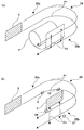
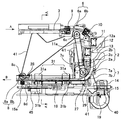
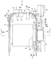
図1は本実施形態の印刷装置(小切手処理装置)の筐体を取り除いた全体斜視図であり、図2は本実施形態の第1搬送路、第2搬送路、第3搬送路の関係を示す概略図であり、図3は印刷装置から一部部材を省略した平面図であり、図4は第1搬送路を示す模式図であり、図5は第2搬送路及び第3搬送路を示す立面図である。 FIG. 1 is an overall perspective view of the printing apparatus (check processing apparatus) according to this embodiment with the housing removed, and FIG. 2 shows the relationship between the first conveyance path, the second conveyance path, and the third conveyance path of this embodiment. FIG. 3 is a plan view in which some members are omitted from the printing apparatus, FIG. 4 is a schematic diagram illustrating the first transport path, and FIG. 5 illustrates the second transport path and the third transport path. FIG.
本実施形態の印刷装置1では、図2(a)または図2(b)に示すように、慨略U字型の形状を有しかつ単票紙Sを水平方向に平行に搬送する第1搬送路P1と、第1搬送路P1と概略直交しかつ単票紙Sまたはロール紙Pを垂直方向に搬送する第2搬送路P2及び第3搬送路P3を有している。印刷装置1は、例えば、銀行の顧客と対応する窓口に設置され、顧客から受け取る単票紙Sである小切手を処理し、ロール紙Pを用いてレシートを発行可能な小切手処理装置である。
In the
(第1搬送路)
まず、第1搬送路P1について説明する。図1において、第1搬送路P1は、外側ガイド2a及び内側ガイド2bによって挟まれた搬送路2cで構成されており、直線部分35a,35bと、両端が直線部分35a,35bに接続されたU字底部分34からなる全体U字型の形状を有している。この第1搬送路P1は、矢印Aの方向に単票紙Sを直線部分35aに沿って搬送し、そして単票紙SをU字底部分34を介して挿入時とは180度向きを変えた後、直線部分35bを介して単票紙Sを矢印Bの方向に排出する水平搬送路である。
(First transport path)
First, the first transport path P1 will be described. In FIG. 1, the 1st conveyance path P1 is comprised by the
直線部分35aには、給紙部3が設けられている。この給紙部3は、第1搬送路P1を搬送されるべき単票紙Sを収納する部位である。この給紙部3は、複数の単票紙Sを自動的に1枚ずつ第1搬送路P1に供給するオートフィーダ機構を有するように構成してもよい。なお、印刷装置1では、単票紙Sが小切手である場合には、原則として裏面が内側ガイド2b側に向けて配置される。
The
第1搬送路P1には、第1搬送ローラ6、第2搬送ローラ7及び排出ローラ8が単票紙Sを搬送する第1の搬送装置として設けられている。第1搬送ローラ6、第2搬送ローラ7及び排出ローラ8は、それぞれ駆動ローラ6a,7a,8aとこの駆動ローラ6a,7a,8aに対して単票紙Sを押し付ける押付ローラ6b,7b,8bを有している。図3に示す例では、駆動ローラ6a,7a,8aと同軸上にはプーリ6c,7c,8cが設けられており、プーリ6c,7c,8c間及び水平方向用紙搬送モータ(Horizontal Paper Feed Motor)40(以降HFモータと呼ぶ)に設けられたプーリ(不図示)間にはベルト41が張架されている。これにより、駆動ローラ6a,7a,8aは、1つのHFモータ40によって駆動される。なお、図3に示すように、排出ローラ8の押付ローラ8bは、回転アーム8dの先端に取り付けられている。そして、アクチュエータ45を駆動することにより、回転アーム8dが回転し、押付ローラ8bが、駆動ローラ8aと接触する閉ポジション(搬送位置)と、駆動ローラ8aから離れた開ポジション(退避位置)を取ることができるようになっている。
In the first conveyance path P1, a first conveyance roller 6, a
ここで、第1搬送ローラ6及び第2搬送ローラ7は、単票紙Sの先端が第2搬送ローラ7へ達したときには、単票紙Sの後端が第1搬送ローラ6よりも手前(上流側、すなわち給紙部3側)に位置する(第1搬送ローラ6による送り代が残っている)ような間隔で配置されている。更に同様に、第2搬送ローラ7及び排出ローラ8は、単票紙Sの先端が排出ローラ8へ達したときには、単票紙Sの後端が第2搬送ローラ7よりも手前(上流側、すなわち給紙部3側)に位置する(第2搬送ローラ7による送り代が残っている)ような間隔で配置されている。
Here, when the leading edge of the cut sheet S reaches the second conveying
第1搬送ローラ6の上流側にはBOF(Bottom of Form)検出器9が、そして第1搬送ローラ6の下流側にはTOF(Top of Form)検出器10がそれぞれ設けられている。これらの検出器9,10は、第1搬送路P1の底部近傍に設けられ、HFモータ40を動作することにより搬送される単票紙Sの先端及び後端を検知する。このBOF検出器9の検出に応じてHFモータ40が駆動され、第1搬送ローラ6、第2搬送ローラ7及び排出ローラ8が、回転を開始する。また、図3で示した例を変更して(例えば複数のモータを用いたり、駆動ローラ6a,7a,8aにクラッチを配置したりして)個々のローラ6,7,8を独立に回転させるように構成してもよい。
A BOF (Bottom of Form)
TOF検出器10と第2搬送ローラ7との間のU字底部分34には、上流側から順にスキャナ11,12及びMICR13が配置されている。
In the
スキャナ11,12は、それぞれ単票紙Sの画像を読み取る画像読取センサである。スキャナ11は単票紙Sの裏面画像を読取可能なように第1搬送路P1の外側ガイド2a側に設けられ、一方スキャナ12は、単票紙Sの表面画像を読取可能なように第1搬送路P1の内側ガイド2b側に設けられている。これらのスキャナ11,12は、第1搬送路P1を介した対向面側に配置された押し付け部材(ローラ)11a,12aによって単票紙Sをスキャナ11,12に押し付けた状態で画像を読み取る。
The
MICR13は、単票紙Sの表面に印刷された磁気インク文字を読み取る磁気読み取りセンサであり、単票紙Sの表面に対向可能なように第1搬送路P1の内側ガイド2b側に設けられている。MICR13は、第1搬送路P1を介した対向面側に配置された押し付け部材(パッド)13aによって単票紙SをMICR13に押し付けた状態で磁気インク文字を読み取る。
The
第2搬送ローラ7と排出ローラ8との間の直線部分35bには、印刷ヘッド14が第1搬送路P1に向けられて配置されている。この印刷ヘッド14は、ガイド軸15aを介して移動可能に構成されたキャリッジ15に載置されており、キャリッジ15を介して印刷領域18と退避位置19との間を移動することができる。この印刷ヘッド14は、印刷領域18にいる状態で、ロール紙収納部20をカバーする開閉蓋25に取り付けられたプラテン24と対向配置されており(図5参照)、この状態で単票紙Sの裏面に印刷可能である。印刷ヘッド14には、インクタンク17からインクが補給されるように構成されており、印刷ヘッド14は、インクの直接交換をすることなく長時間印刷が可能である。
The
また、この印刷ヘッド14は、水平方向に移動する単票紙Sと、後述する垂直方向へ移動するロール紙Pまたは単票紙Sの双方に印刷を行うことが可能である。なお、印刷ヘッド14は複数のノズルを有し、キャリッジ15を移動させずに水平方向に移動する単票紙Sに、少なくとも1行分以上の文字が印刷可能である。
The
印刷ヘッド14の下流側には、排出ローラ8によって構成される排出部4が設けられている。この排出部4は、印刷が終了した単票紙Sを排出ローラ8を介して印刷装置1外部へ排出する。また、排出ローラ8の近傍には、排出検出器28が設けられており、印刷が終了した単票紙Sが排出されたかどうか確認することが可能である。なお、この排出検出器28は、後述する第3搬送路P3に沿って搬送・印刷された単票紙Sの排出の検出を兼ねており、図6に示すように、第1の搬送路P1、第3の搬送路P3の双方にとって、印刷領域18よりも下流側に配置されている。
On the downstream side of the
なお、本実施形態では、スキャナ11,12及びMICR13が設置されているU字底部分34以外の場所では、外側ガイド2aと内側ガイド2bの高さは、搬送される単票紙Sの幅よりも低くなっており、紙詰まり等が発生した場合に、手で容易に取り出せるようになっている。
In the present embodiment, the height of the
次に、この第1搬送路P1における単票紙Sの搬送について説明する。単票紙Sは、使用者によって矢印Aの方向から、第1搬送路P1の直線部分35aに設けられた給紙部3にセットされる。単票紙Sは、この給紙部3から第1搬送路P1に沿って搬送されていく。
Next, the conveyance of the cut sheet S in the first conveyance path P1 will be described. The cut sheet S is set by the user from the direction of the arrow A in the
使用者がによってセットされた単票紙Sの先端が、BOF検出器9に達すると、BOF検出器9は、単票紙Sの先端を検出する。そして、印刷装置1がホストコンピュータ(不図示)から単票紙Sの処理コマンドを受信していた場合、第1搬送ローラ6の駆動ローラ6aは、このBOF検出器9の検出に応じて回転を始める。そして、単票紙Sは、駆動ローラ6aと押付ローラ6bの間にスムーズに挟み込まれ、駆動ローラ6aの回転によってスリップすることなく第1搬送路P1に沿って、U字底部分34の外側ガイド2aの壁に沿って搬送される。
When the leading edge of the cut sheet S set by the user reaches the
第1搬送ローラ6によって搬送された単票紙Sの先端が、TOF(Top of Form)検出器10に達すると、その先に設置されたスキャナ11,12とMICR13の電源が入る。本実施形態の印刷装置1は、ローラの駆動を含めて、必要なときだけ必要な部位に電力を供給するようになっており、無駄な電力の消費を防ぐように構成されている。
When the leading edge of the cut sheet S transported by the first transport roller 6 reaches a TOF (Top of Form)
さらに、単票紙Sが搬送されると、外側ガイド2a側に設置されたスキャナ11は、単票紙Sの裏面の画像を読み取り、そして内側ガイド2b側に設置されたスキャナ12は、単票紙Sの表面の画像を読み取る。更に、内側ガイド2b側に設置されたMICR13は、単票紙Sに予め記載された磁気インク文字の情報を読み取る。
Further, when the cut sheet S is conveyed, the
このスキャナ11、12により生成された画像データは、印刷装置1を制御するホストコンピュータへ転送されることも可能であるし、印刷装置1に設けられた演算処理装置で所定の処理を行うようにしてもよい。また、読み込んだ画像をディスプレイに表示して、小切手等の単票紙Sをチェックする作業の効率化を図るように構成してもよい。このディスプレイは、ホストコンピュータに設置されたものを用いることもできるし、印刷装置1自体に設置することも可能である。
The image data generated by the
これらの取り込んだデータは、印刷装置1内の処理装置又は接続されたホストコンピュータによりデータ処理される。そして、データ処理の結果に応じて第2の印刷媒体であるロール紙Pやバリデーション紙である別の単票紙Sへの印刷を行うように構成してもよい。
These fetched data are processed by a processing device in the
単票紙Sは、TOF検出器10を通過した後に、その先端が第2搬送ローラ7に達すると、駆動ローラ7aと押付ローラ7bの間に挟まれて、駆動ローラ7aの回転によって直線部分35b側へ送り出される。
When the leading edge of the cut sheet S reaches the second conveying
そして、印刷ヘッド14と近接対向する印刷領域18を通過するときに、印刷ヘッド14は、この単票紙Sへの印刷を行う。印刷ヘッド14と単票紙Sの間には、外側ガイド2aがあるが、この印刷領域18では外側ガイド2aに開口が大きく開けられており、印刷ヘッド14と単票紙Sの間には、何ら障害物が無い状態になっている。
Then, the
本実施形態では、印刷ヘッド14は、印刷時には、印刷領域18中の予め定められた位置に固定されており、印刷媒体である単票紙Sが移動することによって所定の印刷が行われるようになっている。なお、印刷ヘッド14は、印刷に必要ない場合には、キャリッジ15とともに退避位置19へ待避可能である。したがって、印刷を行わない場合には、印刷ヘッド14を退避させることにより、搬送される単票紙Sによって印刷ヘッド14が損傷したり、搬送される単票紙Sを汚したりする恐れがない。また、印刷ヘッド14が退避することにより、単票紙S等が紙詰まりを起こす可能性も低くなる。
In the present embodiment, the
印刷ヘッド14で裏面側に印刷が行なわれた単票紙Sは、排出ローラ8で矢印Bの方向へ排出され、駆動ローラ8aと押付ローラ8bの間に挟まれた状態で駆動ローラ8aが回転することによって、印刷装置1の外部へ送り出される。これで、単票紙Sに関する処理は終了する。以上が、第1搬送路に関する説明である。
The cut sheet S printed on the back side by the
(第2搬送路)
次に、図2(a)、図5及び図6を参照しながら、第2搬送路P2について説明する。
(Second transport path)
Next, the 2nd conveyance path P2 is demonstrated, referring Fig.2 (a), FIG.5 and FIG.6.
図5は、図4のV−V矢視断面図であり、図6は、図5の拡大図である。第1搬送路P1の2つの直線部分35a,35bの間には、ロール紙Pを収納するロール紙収納部20が設けられている。ロール紙Pの一端は、このロール紙収納部20から第2搬送路P2に引き出されて、第2搬送路P2に沿って搬送される。
5 is a cross-sectional view taken along the line V-V in FIG. 4, and FIG. 6 is an enlarged view of FIG. 5. A roll
第2搬送路P2は、図2(a)、図5または図6に示すように、このロール紙収納部20からロール紙Pを印刷領域18に向かって搬送して排出するロール紙搬送路であり、直線部分35aと35bとの間に形成されている。この第2搬送路P2は、第1搬送路P1の直線部分35bの一部と重複しており、第1搬送路P1と搬送方向がほぼ直交している垂直搬送路である。
As shown in FIG. 2A, FIG. 5 or FIG. 6, the second transport path P2 is a roll paper transport path that transports the roll paper P from the roll
第2搬送路P2には、図6に示されるように、ロール紙Pを垂直方向に搬送する垂直駆動ローラ22と、垂直駆動ローラ22に対してロール紙Pを押し付ける垂直押付ローラ23と、印刷領域18に露出したロール紙Pに所定のテンションを加えるテンションローラ30とを備えた第2の搬送装置が設けられている。
In the second transport path P2, as shown in FIG. 6, a
これらの垂直駆動ローラ22は、図5に示すようにロール紙収納部20を開閉する開閉蓋25の先端部分に取り付けられている。
These
垂直駆動ローラ22及び垂直押付ローラ23とテンションローラ30との間には、プラテン24と印刷領域18に配置された印刷ヘッド14とが第2搬送路P2の両側に位置するように配置される。また、垂直駆動ローラ22及び垂直押付ローラ23の上方には、ロール紙Pを排出するロール紙排出口36が開口しており、このロール紙排出口36近傍にはロール紙Pを切断するカッタ26が配置されている。
Between the
次に、ロール紙搬送路である第2搬送路P2におけるロール紙Pの搬送について説明する。ロール紙収納部20から引き出されたロール紙Pの一端は、テンションローラ30及びプラテン24を通り、垂直駆動ローラ22と垂直押付ローラ23に挟み込まれるように予めセットされる。このロール紙Pは、テンションローラ30、垂直駆動ローラ22及び垂直押付ローラ23の回転によって、第2搬送路P2を上方に向かって搬送される。そして、印刷ヘッド14と近接対向する印刷領域18を通過するときに、印刷ヘッド14を介してロール紙Pに対する印刷が行なわれる。
Next, the conveyance of the roll paper P in the second conveyance path P2 that is the roll paper conveyance path will be described. One end of the roll paper P drawn out from the roll
ここで、ロール紙Pへの印刷は、印刷ヘッド14がキャリッジ15を介して水平方向に移動しながら1行印刷を行い、複数行印刷する必要がある場合には、一行印刷の終了後、垂直駆動ローラ22を回転させて、ロール紙Pを一行分上方に紙送りした後に再度印刷ヘッド14を水平方向に移動させて2行目以降の印刷を行う。なお、テンションローラ30と垂直駆動ローラ22及び垂直押付ローラ23との間には所定のテンションがかけられており、ロール紙Pはたるむことなく印刷位置を搬送される。
Here, in printing on the roll paper P, when the
そして、ロール紙Pは更に上方へ搬送され、ロール紙排出口36から印刷装置1外部へ排出される。また、ロール紙排出口36近傍に配置されたカッタ26により、排出されたロール紙Pを切断することができるようになっている。
Then, the roll paper P is further conveyed upward and discharged from the roll
このロール紙Pへは、ホストコンピュータから受信した印刷データが印刷される。また、ホストから受信した印刷データ以外にも、スキャナ11,12及びMICR13によって読み込んだデータ自体、又はそれを加工したデータの印刷を行うことができる。すなわち、印刷装置1は、印刷装置1自身が取得したデータを基にロール紙Pへの印刷が可能である。したがって、一連の処理作業を迅速に行うことができる。
Print data received from the host computer is printed on the roll paper P. In addition to the print data received from the host, the data read by the
また、第1搬送路P1、後述する第3搬送路P3で単票紙Sに印刷を行なわれているときは、ロ−ル紙と印刷ヘッド14の間には単票紙Sが存在することが排出検出器28、又は後述するバリデーション検出器27によって確認されているので、単票紙Sに印刷されるべき印刷データがロール紙Pに印刷される恐れはない。そして、ロール紙Pへの印刷への必要な場合には、この単票紙Sが通過又は、取り除かれたこと検出された後、すぐにロール紙Pへの印刷を行うことができるので、作業効率を上げることができる。
Further, when printing is performed on the cut sheet S in the first transport path P1 and the third transport path P3 described later, the cut sheet S exists between the roll sheet and the
(第3搬送路)
次に、図2(b)及び図6を参照しながら、第3搬送路P3について説明する。
(Third transport path)
Next, the 3rd conveyance path P3 is demonstrated, referring FIG.2 (b) and FIG.
第3搬送路P3は、印刷領域18に配置される印刷ヘッド14に対応して設けられ、印刷領域18付近の外側ガイド2aと内側ガイド2bとの間に形成される上部開口37から外側ガイド2aと内側ガイド2bの間に挿入されたバリデーション紙である単票紙Sを搬送する搬送路である。第3搬送路P3は、第2搬送路と一部搬送路が重複しており、第2搬送路P2と同様に、第1搬送路P1と搬送方向がほぼ直交している。すなわち、第3搬送路P3は、第2搬送路P2とともに第1搬送路P1と直交する垂直搬送路である。
The third transport path P3 is provided corresponding to the
この第3搬送路P3には、第3搬送路P3の両側に対向配置されたバリデーション駆動ローラ31aとバリデーション押付ローラ31bを備えている。バリデーション駆動ローラ31aは、プラテン24及びテンションローラ30の下方に配置されており、第3搬送路P3に沿って単票紙Sを上下に搬送可能である。このローラ31a、31bの対を垂直排出ローラ31と呼ぶこともある。)なお、バリデーション駆動ローラ31aと、ロール紙Pを搬送する垂直駆動ローラ22と、不図示の単一の垂直方向用紙搬送モータ(Vertical Paper Feed Motor、以降単に、VFモータと呼ぶ)により選択的に駆動される。即ち、バリデーション駆動ローラ31a、垂直駆動ローラ22は、不図示のクラッチによってVFモータに選択的に接続される。本実施形態では、キャリッジ15を予め決められた位置に移動することにより、VFモータの動力をバリデーション駆動ローラ31a、垂直駆動ローラ22のいずれに伝達するか決められる。
The third transport path P3 includes a
また、バリデーション押付ローラ31bは、図6に示すように、回転アーム31cの先端に取り付けられている。そして、アクチュエータ(不図示)を駆動することにより、回転アーム31cが回転し、バリデーション押付ローラ31bが、バリデーション駆動ローラ31aと接触する閉ポジション(搬送位置)と、駆動ローラ31aから離れた開ポジション(退避位置)を取ることができるようになっている。単票紙Sが第1搬送路P1に沿って搬送される場合や、上方から単票紙Sが挿入される時には、バリデーション押付ローラ31bは退避位置に保持された状態になっている。
Further, the
また、第3搬送路P3の底部近傍には、単票紙Sが第3搬送路P3に挿入されたことを検知するバリデーション検出器27が設置されている。図3に示すように、第1搬送路P1の直線部分35bと、U字底部分34の接続部分には、バリデーション紙である単票紙Sを第3搬送路P3に挿入する時の位置決めガイド29が設けられている。バリデーション検出器27は、単票紙Sが予め決められた位置に単票紙Sがセットされたかどうかを確認するために設けられている。即ち、バリデーション検出器27によって、単票紙Sが位置決めガイド29に沿って、第3搬送路P3の底部までセットされたことが検出される。また、単票紙Sが第3搬送路P3に挿入されたとき、同時に排出検出器28によっても、単票紙Sが検知される。このように、印刷領域18を挟んで配置された2つの検出器27,28を用いることで、予め定められたサイズ以上の用紙が挿入されたことができ、許容されていないサイズ以下の単票紙Sを誤って印刷処理することを防止できる。
In addition, a
次に、第3搬送路P3を介して、帳票等の単票紙Sにバリデーション印刷を行う場合の例を示す。このバリデーション搬送路である第3搬送路P3には、上部開口37から、単票紙Sが挿入される。単票紙Sは、バリデーション駆動ローラ31a,バリデーション押付ローラ31bと干渉することなく、第3搬送路P3の底部まで挿入される。また、このとき、排出ローラ8の押付ローラ8bも、退避位置に保持された状態になっており、単票紙Sは、排出ローラ8と干渉することなく、第3搬送路P3の底部まで挿入される。
Next, an example in the case where validation printing is performed on the cut sheet S such as a form via the third conveyance path P3 will be described. The cut sheet S is inserted from the
印刷装置1がホストコンピュータから、バリデーション印刷を指示するコマンドを受信した状態で、単票紙Sが第3搬送路P3の底部まで挿入されたことがバリデーション検出器27により検知されると、バリデーション押付ローラ31bは、退避位置から搬送位置へ移動して、バリデーション駆動ローラ31aとの間に単票紙Sを挟む。なお同時に、排出検出器28によっても、単票紙Sの有無の検出が行われる。バリデーション検出器27及び排出検出器28の双方によって、単票紙Sが検出されたときのみ、バリデーション押付ローラ31bを、退避位置から搬送位置へ移動させ、一方のみによって単票紙Sが検出されたときは、不図示のLEDによりエラー表示を行い、単票紙Sが所定位置にセットされていないことを使用者に報知する。
When the
そして、図7に示すように、キャリッジ15を水平方向に移動させて、印刷ヘッド14により、バリデーション押付ローラ31b、バリデーション駆動ローラ31aとの間に挟まれた単票紙Sに印刷を行う。これにより、単票紙Sの下端から予め定められた位置(第3搬送路P3の底部から印刷領域18までの距離)に1行分の印刷が行われる。更に印刷を行う場合は、バリデーション駆動ローラ31aを回転させて、単票紙Sを上方へ1行分搬送し、再度キャリッジ15を水平方向に移動させて、印刷ヘッド14により2行目の印刷を行う。
Then, as shown in FIG. 7, the
そして、印刷の終了後、更に、単票紙Sは、上方へ搬送されていき、単票紙Sは、バリデーション押付ローラ31b、バリデーション駆動ローラ31aから外れ、使用者が、上部開口37から露出した単票紙Sを取り出すことが可能となる。使用者によって、単票紙Sが取り出されたことは、排出検出器28の出力によって確認される。以上によって、一連の単票紙Sへの印刷(バリデーション印刷)が終了する。
After the printing is finished, the cut sheet S is further conveyed upward, and the cut sheet S is detached from the
以上のように、本実施形態の印刷装置1には、挿入した単票紙SがUターンして戻ってくるU字型の第1搬送路P1を有するため、作業者は座ったまま、容易に単票紙Sを挿入し、搬送路上で所定の処理が行われた後、容易に単票紙Sを取り出すことができる。また、第1搬送路P1と直交する第2搬送路P2を有するため、レシート等に使うロール紙をU字型搬送路の間に設置することが可能であり、作業者は、座ったまま容易にレシート等を取り出すことができる。また、必要に応じて、第3搬送路P3にバリデーション用の別の単票紙S(バリデーション紙)を挿入し、座ったままバリデーション印刷を行うこともできる。従って、従来に比べて、大幅に作業効率が改善される。
As described above, the
本実施形態によれば、例えば、第1搬送路P1で処理を行った小切手に、更に裏書を行う必要が出た場合には、他の印刷装置を使わずに、作業者は座ったまますばやく作業をすることができる。また、既に読み込んである小切手のデータを、この印刷にフィードバックすることができる。 According to the present embodiment, for example, when it is necessary to perform further endorsement on the check processed in the first transport path P1, the operator can quickly sit down without using another printing apparatus. Can work. Also, the check data that has already been read can be fed back to this printing.
以上まとめると、本実施形態の印刷装置1は、U字型の形状を有する第1搬送路P1と、第1搬送路P1上の第1の印刷媒体である単票紙Sを搬送し排出する第1の搬送装置と、第1搬送路P1と概略垂直に交わる第2搬送路P2または第3搬送路P3と、第2搬送路P2上の第2の印刷媒体であるロール紙Pまたは第3搬送路P3上の第2の印刷媒体である単票紙Sを搬送し排出する第2の搬送装置と、第1搬送路P1上と第2搬送路P2(または第3搬送路P3)上の印刷位置において、第1の印刷媒体である単票紙Sと第2の印刷媒体であるロール紙Pまたは単票紙Sに印刷を行う1つの印刷ヘッド14と、を備えている。
In summary, the
また、本実施形態によれば、第1搬送路P1はU字型の形状をしているため、印刷装置1の第1搬送路P1に挿入された第1の印刷媒体は、第1搬送路P1に沿ってUターンしてくるので、印刷が行なわれて第1搬送路から排出されるときには、装入した位置の隣に排出させることが可能である。従って、この印刷装置1を操作する者は、座ったまま容易に印刷媒体の装入、取り出し作業を行うことができる。
Further, according to the present embodiment, since the first transport path P1 has a U-shape, the first print medium inserted into the first transport path P1 of the
また、第2搬送路P2(または第3搬送路P3)は、第1搬送路P1と概略直交しており、ここを搬送される第2の印刷媒体は、第1の印刷媒体と同じ印刷ヘッドで印刷される。従って、第2搬送路P2(または第3搬送路P3)を、第1搬送路P1のU字型経路の中に収めることができるため、従来不可能であった、2つの印刷機能を1台で行うことができる。 The second transport path P2 (or the third transport path P3) is substantially orthogonal to the first transport path P1, and the second print medium transported there is the same print head as the first print medium. Will be printed. Accordingly, since the second transport path P2 (or the third transport path P3) can be accommodated in the U-shaped path of the first transport path P1, two printing functions that have been impossible in the past are provided by one unit. Can be done.
また本実施形態によれば、印刷ヘッド14は、印刷領域18と、印刷領域18から所定の距離だけ離れた退避位置19との間を往復移動させるキャリッジ15が備えられている。したがって、印刷を行う印刷ヘッド14は、印刷を行わないときには、退避位置19にいるため、印刷ヘッド14の損傷や汚れを防ぎ、印刷媒体と印刷ヘッド14の干渉による紙詰まりの危険性を回避することができる。
Further, according to the present embodiment, the
また、本実施形態によれば、印刷装置1は、第1搬送路P1の少なくとも片側に配置され、第1の印刷媒体に記載された磁気インク情報を読み取る磁気インク文字読み取り装置であるMICR13が備えられている。したがって、本実施形態の印刷装置1は、印刷のみならず、U字型の第1搬送路P1上を第1の印刷媒体である単票紙S(例えば小切手)が搬送される間に、この単票紙Sに記載された磁気インクの情報を、MICR13で読み取ることができる。印刷装置1は、取得した磁気インクの情報(データ)を、ホストコンピュータに伝送したり、印刷装置1内の図示せぬ制御部で処理をしたり、後に行なわれる印刷工程にフィードバックすることも可能である。
Further, according to the present embodiment, the
本実施形態の印刷装置1は、第1搬送路P1に沿って設置され、単票紙Sの画像を読み取る画像読み取り装置(スキャナ11,12)を備えている。したがって、印刷装置1は、印刷やMICR13による磁気文字読み取りだけでなく、第1搬送路の両側に設置されたスキャナ11,12で、単票紙Sの画像を取り込むことが可能なことである。このデータは、上述のMICR13による読み込みデータと同様の処理も可能であるし、この画像をディスプレイの表示して、例えば小切手のチェック作業の効率化を図ることもできる。
The
また、本実施形態の印刷装置1において、印刷ヘッド14は、インクジェットプリンタである。印刷方式としては、様々な方式を採用することが可能であるが、第1搬送路P1と第2搬送路P2(または第3搬送路P3)の異なる搬送路上の印刷媒体を1つの印刷ヘッド14で印刷することを考慮すれば、インクジェットプリンタは、最適な方式のひとつと考えられる。
In the
第1の印刷媒体としては、単票紙Sのような紙だけではなく様々なものが考えられるが、本実施態様のように、小切手に代表される単票紙Sは、複数の印刷装置を使用する場合、ばらばらになる恐れもあり、ハンドリングが煩雑になる。したがって、単票紙Sを印刷装置1で処理することによって、効率よい処理を行うことができる。
As the first print medium, various media as well as paper such as the cut paper S are conceivable. However, as in the present embodiment, the cut paper S represented by a check includes a plurality of printing apparatuses. When used, there is a possibility that it may be separated, and handling becomes complicated. Therefore, efficient processing can be performed by processing the cut sheet S with the
また、本実施形態では、第3搬送路P3を使って、単票紙Sに印刷を行うことができる。例えば、小切手を上述の第1搬送路P1に流して、データ読み取りや裏書を行った後、再度裏書等を行う必要がある場合もある。本実施形態の印刷装置1は、そのような場合、別の印刷装置を使用することなく、読み取ったデータのフィードバックを受けながら必要な印刷を、第3搬送路P3に小切手を搬送させることにより実行することが可能である。したがって、従来に比べて、作業ミスの少ない効率の良い処理を行うことができる。
In the present embodiment, printing on the cut sheet S can be performed using the third transport path P3. For example, there is a case where it is necessary to carry out the endorsement or the like again after flowing the check on the above-mentioned first transport path P1 and performing data reading or endorsement. In such a case, the
また、本実施形態では、第3搬送路P3の排出側から装入された第2の印刷媒体としての単票紙Sを、第2の搬送装置で印刷位置へ搬送し、印刷位置において印刷ヘッド14で印刷を行い、第2の搬送装置で再び第3搬送路P3の排出側へ排出することが可能である。これにより、本実施形態の印刷装置1は、第3搬送路P3を使用して、バリデーション印刷を行うことができる。従来は、別の印刷装置によって、バリデーション印刷を行っていたが、印刷装置1では1台ですべてを行うことが可能であり、また、読み取ったデータをそのまま利用できる。従って、印刷媒体のハンドリングミス、データ入力ミス、作業の遅延等の問題を解決できる。
In the present embodiment, the cut sheet S as the second print medium loaded from the discharge side of the third transport path P3 is transported to the print position by the second transport device, and the print head is printed at the print position. It is possible to print at 14 and discharge again to the discharge side of the third transport path P3 by the second transport device. Thereby, the
また、印刷装置1は、第2の印刷媒体としてロール状に巻き取られた連続紙(ロール紙)を用いることが可能である。従来は、別の印刷装置で、レシート等を印刷しており、データ入力ミスや作業の遅延等の問題が発生していたが、本実施態様によれば、第2搬送路P2を介してロール紙Pを搬送し、このロール紙Pに印刷を行い出力することで1台の印刷装置1だけを用いて、処理を行うことが可能である。
Moreover, the
(単票紙印刷に関するモード)
本実施形態の印刷ヘッド14は、キャリッジ15に載置されており、第1搬送路P1の直線部分35bに沿って水平方向に印刷領域18に移動可能である。したがって、第1搬送路P1を搬送される単票紙Sへの印刷としては、単票紙Sを固定した状態で印刷ヘッド14を水平方向に移動させることにより印刷を行う単票紙固定モードと、印刷ヘッド14を固定した状態で単票紙Sを水平方向に移動させることにより印刷を行う印刷ヘッド固定モードの2つのモードが考えられる。
(Mode for cut sheet printing)
The
印刷ヘッド固定モードの場合には、印刷ヘッド14の位置を固定し、この印刷ヘッド14の前方を通過する単票紙Sに対して、印刷ヘッド14からインクを吐出させて単票紙Sに対する印刷を行う。
In the print head fixed mode, the position of the
この印刷ヘッド14を固定して、単票紙Sを移動させながら印刷を行う印刷ヘッド固定モードにおいては、単票紙Sを一旦停止させる必要がない。したがって、印刷ヘッド固定モードでは、U字底部分34から搬送される単票紙Sの搬送スピードを落とすことなく印刷を行うことができる。すなわち、印刷ヘッド固定モードにおいては、単票紙Sの搬送スピードが低下しないため、高速な単票紙Sの処理を行うことが可能である。
In the print head fixing mode in which printing is performed while the
一方、単票紙固定モードの場合には、図8(b)に示すように、単票紙Sを印刷ヘッド14の前面にて一旦停止させ、キャリッジ15を介して印刷ヘッド14を単票紙Sの搬送方向と平行に動かしながらインクを吐出させて、単票紙Sへの印刷を行う。
On the other hand, in the cut sheet paper fixing mode, as shown in FIG. 8B, the cut sheet S is temporarily stopped on the front surface of the
この単票紙固定モードは、例えば、U字底部分34において読み取られた画像データまたは磁気インク文字データの読取結果に基づく印刷を行う場合に有効である。
This cut sheet paper fixing mode is effective, for example, when printing is performed based on the reading result of image data or magnetic ink character data read at the
図8(a)に示すように、印刷ヘッド固定モードにおいて、U字底部分34において読み取られた画像データまたは磁気インク文字データの読取結果に基づく印刷を行う場合、単票紙Sは、画像データまたは磁気インク文字データの読取結果が判明するまで、U字底部分34から排出された位置(より厳密には、MICR13による磁気インクの読取が終了した位置)よりも下流側にて単票紙Sが一端停止させなければならない。この場合、印刷ヘッド14は、画像データまたは磁気インク文字データの読取結果が判明後に単票紙Sの搬送が再開されて単票紙Sが定常走行に入った位置以降に設置する必要がある。したがって、印刷ヘッド固定モードにおいて、画像データまたは磁気インク文字データの読取結果に基づく印刷を行おうとすると、画像データまたは磁気インク文字データの読取結果に基づく印刷を行わない場合と比べて、図8(a)に示す長さLだけ直線部分35bの長さが長くなってしまう。この直線部分35bの長さがLだけ長くなることは、非常にスペースの限られた銀行の窓口への印刷装置1の設置に関しては、大きな障害となってしまい、好ましくない。
As shown in FIG. 8A, in the print head fixing mode, when printing based on the reading result of the image data or magnetic ink character data read in the
一方、図8(b)に示すように単票紙固定モードでは、キャリッジ15を介して印刷ヘッド14を単票紙Sの搬送方向と平行に動かすことによって、単票紙Sを停止させたまま単票紙Sへの印刷を行う。この場合には、単票紙Sの搬送を停止させない従来の搬送路と全く同じ長さで、上述の図8(a)と同じ機能を果すことができる。
On the other hand, as shown in FIG. 8B, in the cut sheet paper fixing mode, the cut sheet S is kept stopped by moving the
具体的には、単票紙Sの後端が、U字形状部分34を通過し終えて直線部分35bに入ったところで、単票紙Sの搬送が停止される。この単票紙Sの搬送は、例えば、印刷範囲の最先部(排出ローラ8側)に設けられた排出検出器28による用紙検出をトリガーとし、単票紙Sの先端が排出検出器28に到達したときに搬送を停止させるようにしてもよい。また、その他、単票紙Sの後端側を検知する等、様々な方法を採ることができる。
Specifically, when the trailing edge of the cut sheet S finishes passing through the
以上のような単票紙固定モードの場合、スキャナ11,12またはMICR13による読み取りにおいて何らかのエラーが発生した場合には、印刷ヘッド14による印刷を行わずに、単票紙Sの搬送を再開させて単票紙Sを排出することができる。これによって、例えば、単票紙Sが小切手の場合には、従来の無効な裏書がなされてしまう問題を防止することができる。
In the cut sheet paper fixing mode as described above, if any error occurs in reading by the
また、単票紙固定モードの場合には、読み取ったデータの処理をした結果や、スキャナで読み取った画像をディスプレイへ映し出して目視チェックした結果等を、フィードバックして印刷することもできる。 In the cut sheet paper fixing mode, the result of processing the read data, the result of visually checking the image read by the scanner on the display, and the like can be fed back and printed.
なお上記説明では、単票紙S及び印刷ヘッド14の何れか一方を停止させて、他方を移動させることにより単票紙Sへの印刷を行ったが、単票紙Sと印刷ヘッド14の両方を同時に移動させながら印刷を行うことも可能である。特に、単票紙Sを排出部4へ搬送しながら、印刷ヘッド14をそれと反対側へ移動させることにより、最も高速な印刷を行うことができる。これは、緊急処理等が必要な場合には、有効な手段である。
In the above description, printing is performed on the cut sheet S by stopping one of the cut sheet S and the
以上、本実施形態の印刷装置1では、印刷ヘッド14は固定されているか又は印刷媒体の搬送方向と平行な方向に移動させるかのモードを選択することができきる。特に、印刷ヘッド14が印刷媒体の搬送方向と平行に移動する場合には、この印刷ヘッドの移動によって、従来実現できなかった様々な態様の印刷を行うことができる。
As described above, in the
すなわち、本実施形態の印刷装置1は、印刷媒体を停止させて、キャリッジ15に搭載された印刷ヘッド14をこの印刷媒体の搬送方向と平行に移動させることで、印刷を行うことが可能である。従来の固定した印刷ヘッドを使用する場合には、一度、印刷媒体の搬送を止めて、その後に印刷を行うためには、印刷媒体が停止した位置から搬送を再開した先に印刷ヘッドを設置する必要があり、更に先の方まで搬送路を取る必要があった。しかし、本実施形態では、従来の搬送路を延長することなく、印刷媒体を止めて印刷が可能である。したがって、銀行の窓口等のような、設置スペースや作業スペースが限られている場合でも、スペースを無意味に占有することが無く、有効にスペースを活用することができる。
That is, the
(単票紙排出の搬送方向の選択)
本実施形態において、第1搬送路P1を搬送される単票紙Sは、スキャナ11,12、MICR13等の読取装置による読取結果に応じて、搬送方向を変化させるように構成することができる。
(Selection of conveyance direction for cut sheet discharge)
In the present embodiment, the cut sheet S conveyed through the first conveyance path P1 can be configured to change the conveyance direction according to the reading result by the reading device such as the
以下、検出器の読取結果に応じて、単票紙Sの搬送方向を変化させる実施形態について説明する。 Hereinafter, an embodiment in which the conveyance direction of the cut sheet S is changed according to the reading result of the detector will be described.
この実施形態では、印刷装置1は、スキャナ11,12またはMICR13の読み取り結果に応じて、第1搬送路P1の直線部分35bにて、それまでの搬送方向と同じ方向である矢印B(図1参照)の方向へ単票紙Sを排出するか、それまでの排出方向と概略直交した上方の矢印C(図1参照)の方向へ単票紙Sを排出するかを選択する。
In this embodiment, the
ここで、矢印Bの方向へ排出する場合には、図3及び図4に示す排出ローラ8からなる排出装置を備えた排出部4で構成される“第1の排出手段”によって行われる。また、矢印Cの方向へ排出する場合は、図3に示す垂直排出ローラ31からなる排出装置と垂直搬送路(第3搬送路P3に相当)から構成される“第2の排出手段”によって行われる。
Here, when discharging in the direction of the arrow B, it is performed by the “first discharging means” configured by the discharging unit 4 including the discharging device including the discharging
第1の排出手段によって排出される場合であっても、また第2の排出手段によって排出される場合であっても、単票紙Sが印刷領域18に配置された印刷ヘッド14と近接対向する時点で、単票紙Sへの印刷を行うことができる。また、矢印Bの方向及び矢印Cの方向の何れか一方への排出を選択したときには印刷を行わないように設定することも可能である。本実施形態では、印刷時には印刷ヘッド14は固定されており、単票紙が移動することで印刷が行われる。勿論、印刷ヘッド14が移動しながら印刷を行うように構成してもよい。
Whether the sheet is discharged by the first discharging means or the second discharging means, the cut sheet S is in close proximity to the
本実施形態では、単票紙Sが給紙部3から搬送されて、単票紙Sの先端部が排出ローラ8に挟み込まれ、第2搬送ロ―ラ7から排出ローラ8へ受け渡しが行われる位置に達したときに、この排出ローラ8の近傍に設置された排出検出器28によって用紙検出が行われる。そしてこの排出検出器28が出力した検出信号に応じて、単票紙Sの搬送を停止させたり、単票紙Sを排出する排出手段の選択を行ったりすることができる。
In the present embodiment, the cut sheet S is transported from the
排出手段の選択に当たっては、スキャナ11,12又はMICR13の読み取りエラーが発生したか否か、その他読み取りデータの不具合があるか否かに基づいて行われる。この判定は、印刷装置1に設置された演算器によって行われる。なお、外部に設置されたホストコンピュータによって判定が行われるように構成してもよい。
Selection of the discharging means is performed based on whether or not a reading error of the
図9(a)〜図9(c)は、単票紙Sが給紙部3に供給されてから、排出手段の選択がなされるまでの動きを模式化して示す図である。
FIG. 9A to FIG. 9C are diagrams schematically showing the movement from the time when the cut sheet S is supplied to the
図9(a)は、単票紙Sが給紙部3へ供給されたところを示している。単票紙Sが1枚1枚挿入される場合には、BOF検出器9の検出によって、また、オートフィーダでストックされた単票紙Sが供給される場合には、図示せぬASF検出器の検出によって、第1搬送ローラ6、第2搬送ローラ7、排出ローラ8等を駆動するHFモータ40を起動させる。
FIG. 9A shows that the cut sheet S is supplied to the
図9(b)は、第1搬送ローラ6によって単票紙Sが搬送され、単票紙Sの先端がTOF検出器10の位置に達したところを示す。このTOF検出器10による検出によって、スキャナ11,12やMICR13の通電が開始される。また、以降の単票紙Sの位置は、モータStep数で管理することになる(他の実施形態でも同様)。
FIG. 9B shows that the cut sheet S is transported by the first transport roller 6 and the leading edge of the cut sheet S has reached the position of the
図9(c)は、単票紙Sが、第2搬送ローラ7から離れて、排出ローラ8に挟み込まれたところを示す。この位置で、排出検出器28によって単票紙Sが検出され、排出方向の選択がなされる。
FIG. 9C shows a state where the cut sheet S is separated from the
本実施形態では、スキャナ11,12またはMICR13の読み取りエラーや読み取りデータの不具合がないと判断された場合、単票紙Sは、それまでの搬送方向と同じ矢印Bの方向へ排出され、一方、スキャナ11,12またはMICR13の読み取りエラーや読み取りデータの不具合があると判定された場合には、それまでの搬送方向と概略直交した上方の矢印Cの方向へ排出される。
In the present embodiment, when it is determined that there is no reading error of the
水平方向への排出は、駆動ロ―ラ8aと押付ロ―ラ8bからなる排出ローラ8によって行われ、上方への排出は、図3に示すバリデーション駆動ローラ31aとバリデーション押付ローラ31bからなる垂直排出ローラ31によって行われる。
The discharge in the horizontal direction is performed by a
前述したように、バリデーション押付ローラ31bがバリデーション駆動ローラ31aと接触する閉ポジション(搬送位置)と、バリデーション押付ローラ31bがバリデーション駆動ローラ31aと離れている開ポジション(退避位置)を取ることができる。ここで、バリデーション駆動ローラ31aは、単票紙Sが搬送される搬送ラインよりも、わずかにオフセットされて配置されており、開ポジションのときには単票紙Sと接触しないような位置に設置されている。また、排出ローラ8の押付ローラ8bも、駆動ローラ8aと接触する閉ポジション(搬送位置)と、駆動ローラ8aから離れた開ポジション(退避位置)を取ることができるようになっている。
As described above, a closed position (conveying position) where the
また、閉ポジションのときには、バリデーション押付ローラ31bはバネ力によって、バリデーション駆動ローラ31a側に付勢されており、バリデーション駆動ローラ31aとバリデーション押付ローラ31bとで、単票紙Sを挟み込む形となる。本実施形態では、搬送ラインからオフセットはほんのわずかであり、単票紙Sの先端部の挟み込みや搬送には全く問題がないように構成されている。この排出方向の選択が行われるときの初期状態は、排出ローラ8が閉ポジションになっており、垂直排出ローラ31が開ポジションになっている。
In the closed position, the
もし、読み取りエラーや読み取りデータの不具合がないと判定された場合には、排出ローラ8は閉ポジションを維持し、垂直排出ローラ31は開ポジションを維持するように指示が出される。したがって、単票紙Sは、垂直排出ローラ31とは接触せずに、排出ローラ8によって搬送される。
If it is determined that there is no reading error or reading data defect, an instruction is issued to maintain the
単票紙Sが印刷領域18を通過するときに、印刷ヘッド14によって単票紙Sに印刷を行うこともできるし、印刷を行わずに単票紙Sをそのまま通過させることもできる。そして、単票紙Sは、そのまま搬送され、矢印Bの方向へ排出される。
When the cut sheet S passes through the
一方、読み取りエラーや読み取りデータの不具合があると判定された場合には、まず、排出ローラ8は閉ポジションから開ポジションを取るように指示が出され、水平方向の搬送が停止する。そして、次に、垂直排出ローラ31が、開ポジションから閉ポジションを取るように指示されて、単票紙Sを挟み込む。この状態で、単票紙Sは排出ローラ8とは接触せずに、垂直排出ローラ31によって上方へ搬送され矢印Cの方向に排出される。
On the other hand, when it is determined that there is a reading error or reading data defect, first, the
このとき単票紙Sは、印刷ヘッド14と近接対向する位置にあるときに、印刷ヘッド14によって印刷を行うことができる。なお、単票紙Sが上方へ移動することによって、従来の水平搬送路のみの場合には不可能であった、複数行を印刷することも可能となる。したがって、より多くの情報を単票紙Sに記載することができるようになる。
At this time, the cut sheet S can be printed by the
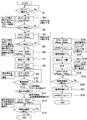
図10は、上述した単票紙Sが給紙部3へ供給されてから、所定の排出方向へ排出されるまでの制御フローを示すフローチャートである。フロー図の矢印でつながれた各ブロックは、主に搬送、排出ローラの制御を示す。このブロックの横に記載されたブロック(互いに連結されていないブロック)は、各ステップで行われるその他のアクションを示している。
FIG. 10 is a flowchart showing a control flow from when the above-described cut sheet S is supplied to the
まず、印刷装置1がホストコンピュータから単票紙Sの処理コマンドを受信した後、単票紙Sが挿入されたら、BOF検出器9が単票紙Sの存在を感知し、HFモータ40が起動する。そして、搬送装置によって単票紙Sが搬送され、TOF検出器10が単票紙Sの存在を感知するとスキャナ11,12やMICR13の電源が入れられる。この後からは、HFモータ40のステップ数の管理によって、単票紙Sの搬送位置を管理する(ステップS1〜S5)。なお、ステップS2とステップS3の間で、所定ステップ(1000ステップ)モータを駆動しても、TOF検出器で単票紙Sの先端が検出されない場合は、モータを停止し、不図示のLEDを用いて、「紙搬送エラー」を使用者に報知する。同様に、ステップS4とステップS5の間で、所定ステップ(2400ステップ)モータを駆動しても、TOF検出器で単票紙Sの後端が検出されない場合は、HFモータ40を停止し、「紙搬送エラー」を使用者に報知する。また、単票紙Sの先端が検出される(ステップS2)の前後では、単票紙Sを搬送する速度が異なる。即ち、本実施形態では、ステップS2ではHFモータ40の駆動速度は200PPS(パルス/秒)であり、ステップS4では1100PPSでモータを駆動している。
First, after the
単票紙Sの後端がTOF検出器10を通過したと感知した後に(ステップS5)、更にHFモータ40を所定ステップ(速度1100PPSで、366ステップ)駆動し(ステップS6)、排出ローラ8を閉ポジションにする指令を出す(ステップS7)。そして、排出検出器28によって単票紙Sが検出されるまで単票紙Sの搬送が行われる。この間に、スキャナ11,12やMICR13によって各種情報の取得が行われる。そして、排出検出器28で、単票紙Sの先端が排出検出器の位置に到達したことを検知(ステップS10)すると、排出方向の選択が行われる(ステップS11)。
After sensing that the trailing edge of the cut sheet S has passed through the TOF detector 10 (step S5), the
もし、スキャナ11,12やMICR13の読み取りエラーやデータの不具合がなければ、そのまま単票紙Sの搬送が続けられ矢印B方向に排出される。本実施形態では、排出検出器28が、単票紙Sの後端が通過したことを検知すると排出が完了したと判断されて、一連の処理が終了する(ステップS12,S13)。
If there is no reading error of the
また、もし、スキャナ11,12やMICR13の読み取りエラーやデータの不具合がある場合には、まず、HFモータ40を所定量(39ステップ)逆転し、単票紙を微小量戻す(ステップS14)。その後、キャリッジ15をCRIポジションに移動し、VFモータの動力を、ロ−ル紙を搬送する垂直駆動ローラ22から、バリデーション駆動ローラ31aに伝達されるようにクラッチを切り換える(ステップS16)。その後、排出部のローラのポジションを垂直排出へ切り換える。つまり、排出ローラ8は開ポジションとし、垂直排出ローラ31は閉ポジションとする(ステップS17)。そして、単票紙Sを上方へ搬送しながら、印刷ヘッド14によって印刷を行う(ステップS18)。更に上方へ搬出する(ステップS19)と、単票紙Sは、バリデーション押付ローラ31b、バリデーション駆動ローラ31aから外れ、使用者が、上部開口37から露出した単票紙Sを取り出すことが可能となる。使用者によって、単票紙Sが取り出されたことは、排出検出器28の出力によって確認され(ステップS20)、これにより、VFモータの動力を、ロ−ル紙を搬送する垂直駆動ローラ22に伝達されるようにクラッチを切り換え、ローラポジションを、元の水平に排出するポジションに戻し、一連の処理が終了する(S14〜S22)。
If there is a reading error or data defect of the
本実施形態によれば、例えば小切手を銀行の窓口で処理する場合、印刷装置1はU字型の搬送路を有するので、銀行員は椅子に座ったまま、単票紙Sとしての小切手の挿入と取り出しが容易に行える。そして、印刷装置1は、スキャナ11,12またはみCR13の読み取りエラーや読み取りデータの不具合が発生した場合には、自動的に従来の水平の搬送方向と異なる上方へ小切手を排出するので、銀行員は、すぐに異常に気づき、迅速な対応をすることができる。また、特に、複数の小切手を連続的に処理する場合では、読取結果に応じて搬送方向を分けることにより、問題のある小切手が他の小切手と混ざることなく識別できるので非常に有効である。
According to the present embodiment, for example, when processing a check at a bank counter, the
また、本実施形態の応用例として、下記のような形態も考えられる。 Moreover, the following forms can also be considered as an application example of the present embodiment.
本応用例では、検出器の読み取りエラーや読み取りデータの不具合が発生したか否かにかかわらず、必ず、単票紙の先端が排出検出器28によって検出された位置近傍で、で単票紙Sの搬送を止める。そして、搬送を止めている間に、読み取ったデータの処理を行ったり、スキャナで読み込まれた画像をディスプレイに映し出したりして、目視で日付や署名のチェック等を行う。
In this application example, regardless of whether a reading error of the detector or a defect in the reading data has occurred, the cut sheet S is always near the position where the leading edge of the cut sheet is detected by the
その結果、不具合があるときには、そのまま水平の”第1の排出手段”を使用して、印刷をせずに排出する。また、不具合がなかった場合には、垂直の”第2の排出手段”を使用し、印刷ヘッドで裏書を行ってから排出する。 As a result, when there is a problem, the horizontal "first discharge means" is used as it is, and the sheet is discharged without printing. If there is no problem, the vertical “second discharging means” is used, and the paper is endorsed by the print head before discharging.
以上の方法によって、小切手の読み取り結果をフィードバックして、裏書を行うことが可能となり、従来のような無効な裏書がなされ、結果として複数の裏書がなされる問題を防止することができる。 According to the above method, it becomes possible to feed back the check reading result and perform the endorsement, and it is possible to prevent a problem that a conventional invalid endorsement is made and a plurality of endorsements are made as a result.
以上、本実施形態では、印刷媒体である単票紙Sの排出方向を、予め定められた条件にしたがって選択することができる。よって、印刷媒体を、事前に設定した条件に従って識別し、グループ分けを行うことができる。また、各々の排出口に別の搬送装置を設置すれば、ある条件に従って、異なる場所へ配送することも可能である。例えば、印刷媒体に識別標識が付けてあれば、それに従って、配送させることも容易に行うことができる。 As described above, in the present embodiment, the discharge direction of the cut sheet S that is a printing medium can be selected according to a predetermined condition. Therefore, the print media can be identified and grouped according to preset conditions. In addition, if another transport device is installed at each discharge port, it is possible to deliver to different places according to certain conditions. For example, if an identification mark is attached to the print medium, it can be easily delivered according to the identification mark.
また、本実施形態によれば、例えば、MICR13やスキャナ11,12での読み取りエラーが発生したり、読み取ったデータに不具合があったりした場合に、搬送方向のまま排出するか、それとも垂直方向に排出するか、条件に応じて、排出手段を選択して排出できることに特長がある。従って、問題のある印刷媒体だけを異なる排出口へ排出させて、容易に識別できるようにすることができる。
Further, according to the present embodiment, for example, when a reading error occurs in the
特に、印刷媒体を連続的に流す場合には、同じ排出口へ排出すると、正常なものと問題のあるものが混在してしまい、後で、仕分けをすることは非常に困難である。従って、このような場合には、大きな効果が得られる。 In particular, when the print medium is continuously flowed, if the print medium is discharged to the same discharge port, normal ones and problematic ones are mixed, and it is very difficult to sort them later. Therefore, in such a case, a great effect can be obtained.
S 単票紙 P ロ-ル紙
P1 第1搬送路 P2 第2搬送路
P3 第3搬送路 1 印刷装置
2a 外側ガイド 2b 内側ガイド
3 給紙部 4 排出部
6 第1搬送ローラ 7 第2搬送ローラ
8 排出ローラ 9 BOF検出器
10 TOF検出器 11 スキャナ(裏面)
12 スキャナ(表面) 13 MICR
14 印刷ヘッド 15 キャリッジ
17 インクタンク 18 印刷領域
19 待避位置 20 ロール紙収納部
22 垂直駆動ローラ 23 垂直押付ローラ
24 プラテン 25 開閉蓋
26 カッタ 27 バリデーション検出器
28 排出検出器 29 位置決めガイド
30 テンションローラ 31 垂直排出ローラ
40 HFモータ 41 ベルト
S sheet paper P roll paper P1 first transport path P2 second transport path P3
12 Scanner (surface) 13 MICR
DESCRIPTION OF
Claims (4)
前記第1搬送路に概略直交するように配置され、単票紙を搬送する第3搬送路と、
前記第1搬送路と前記第3搬送路が交差する印刷領域に設置され、各々の販送路から搬送されてきた単票紙に印刷を行う印刷ヘッドと、
当該印刷ヘッドを搭載し、前記第1搬送路の搬送方向と平行に前記印刷ヘッドを移動させて、前記単票紙を前記第3搬送路の搬送方向に搬送させることで、前記第1搬送路の搬送方向と平行な複数の行を印刷するキャリッジと、
前記単票紙に予め印刷された磁気インクの情報を読み取る磁気インク文字読み取り装置と、
前記単票紙の画像を読み取るスキャナと、を備え、
前記磁気インク文字読み取り装置及び前記スキャナによる前記単票紙の読み取りの結果に応じて、前記単票紙の搬送を停止させて印刷を行い、
前記単票紙の前記読み取りの結果に応じて、前記第1搬出送路の排出方向へ排出するか、前記第3搬送路の排出方向へ排出するか選択可能であることを特徴とする印刷装置。
A first transport path for transporting cut paper,
A third conveyance path that is arranged so as to be substantially orthogonal to the first conveyance path and conveys the cut sheet;
A print head that is installed in a printing region where the first conveyance path and the third conveyance path intersect, and prints on a cut sheet conveyed from each sales path;
The first transport path is mounted by mounting the print head, moving the print head in parallel with the transport direction of the first transport path, and transporting the cut sheet in the transport direction of the third transport path. A carriage for printing a plurality of lines parallel to the transport direction of
A magnetic ink character reading device for reading information of magnetic ink pre-printed on the sheet paper;
A scanner for reading the image of the cut sheet,
The magnetic ink character reader and according to the result of reading of the single-cut sheet by the scanner, have rows printed stops the conveyance of the cut sheet paper,
According to a result of the reading of the cut sheet, it is possible to select whether to discharge in the discharge direction of the first carry-out path or in the discharge direction of the third transport path. .
The printing apparatus according to claim 1, wherein the first transport path has a substantially U shape.
And generally perpendicular to the first conveying path, a second conveying path for conveying the roll paper, the print head can be of any claims 1 to 2 performing printing on the roll paper is conveyed to the second conveyance path A printing apparatus according to claim 1.
前記第1搬送路上を搬送される前記単票紙に予め印刷された磁気インク文字を読み取るステップと、
前記第1搬送路上を搬送される前記単票紙の画像をスキャナで読み取るステップと、
前記磁気インク文字及び前記スキャナによる読み取り結果に応じて、前記単票紙の搬送を停止させ、前記単票紙の第1搬送路の搬送方向と平行に前記印刷ヘッドを移動させて印刷を行うステップと、を備え、
前記単票紙を搬送するステップは、前記単票紙の前記読み取りの結果に応じて、前記第1搬出送路の排出方向へ排出するか、前記第3搬送路の排出方向へ排出するか選択するステップであることを特徴とする印刷方法。 Conveying the cut sheet along the first conveying path;
Reading magnetic ink characters pre-printed on the cut sheet transported on the first transport path;
Reading an image of the cut sheet conveyed on the first conveyance path with a scanner;
The step of stopping the conveyance of the cut sheet according to the magnetic ink characters and the reading result by the scanner, and performing the printing by moving the print head in parallel with the conveyance direction of the first conveyance path of the cut sheet And comprising
The step of conveying the cut sheet selects whether to discharge in the discharge direction of the first carry-out path or in the discharge direction of the third transfer path according to the result of the reading of the cut sheet A printing method characterized by comprising the steps of:
Priority Applications (1)
| Application Number | Priority Date | Filing Date | Title |
|---|---|---|---|
| JP2004014918A JP4561106B2 (en) | 2003-01-24 | 2004-01-22 | Printing apparatus and printing method |
Applications Claiming Priority (4)
| Application Number | Priority Date | Filing Date | Title |
|---|---|---|---|
| JP2003016784 | 2003-01-24 | ||
| JP2003016785 | 2003-01-24 | ||
| JP2003016786 | 2003-01-24 | ||
| JP2004014918A JP4561106B2 (en) | 2003-01-24 | 2004-01-22 | Printing apparatus and printing method |
Publications (3)
| Publication Number | Publication Date |
|---|---|
| JP2004243766A JP2004243766A (en) | 2004-09-02 |
| JP2004243766A5 JP2004243766A5 (en) | 2006-12-07 |
| JP4561106B2 true JP4561106B2 (en) | 2010-10-13 |
Family
ID=33033260
Family Applications (1)
| Application Number | Title | Priority Date | Filing Date |
|---|---|---|---|
| JP2004014918A Expired - Fee Related JP4561106B2 (en) | 2003-01-24 | 2004-01-22 | Printing apparatus and printing method |
Country Status (1)
| Country | Link |
|---|---|
| JP (1) | JP4561106B2 (en) |
Families Citing this family (2)
| Publication number | Priority date | Publication date | Assignee | Title |
|---|---|---|---|---|
| JP2007283553A (en) | 2006-04-13 | 2007-11-01 | Seiko Epson Corp | Method for controlling printing medium processor and printing medium processor |
| JP5003318B2 (en) * | 2007-07-04 | 2012-08-15 | セイコーエプソン株式会社 | Printing system, printer, and printer control method |
Citations (4)
| Publication number | Priority date | Publication date | Assignee | Title |
|---|---|---|---|---|
| JP2001272830A (en) * | 2000-03-28 | 2001-10-05 | Fuji Xerox Co Ltd | Original sorting device |
| JP2002160414A (en) * | 2000-11-24 | 2002-06-04 | Canon Inc | Ink jet recorder |
| JP2002200762A (en) * | 2000-12-28 | 2002-07-16 | Seiko Epson Corp | Ink jet recorder |
| JP2002255393A (en) * | 2001-02-26 | 2002-09-11 | Oki Electric Ind Co Ltd | Medium processing device |
Family Cites Families (3)
| Publication number | Priority date | Publication date | Assignee | Title |
|---|---|---|---|---|
| JPH05201095A (en) * | 1992-01-28 | 1993-08-10 | Tokyo Electric Co Ltd | Impact printer |
| US5533817A (en) * | 1995-05-19 | 1996-07-09 | International Business Machines Corporation | Biaxial printer |
| JP3871008B2 (en) * | 1998-02-12 | 2007-01-24 | セイコーエプソン株式会社 | Platen mechanism, printing apparatus using the same, and control method therefor |
-
2004
- 2004-01-22 JP JP2004014918A patent/JP4561106B2/en not_active Expired - Fee Related
Patent Citations (4)
| Publication number | Priority date | Publication date | Assignee | Title |
|---|---|---|---|---|
| JP2001272830A (en) * | 2000-03-28 | 2001-10-05 | Fuji Xerox Co Ltd | Original sorting device |
| JP2002160414A (en) * | 2000-11-24 | 2002-06-04 | Canon Inc | Ink jet recorder |
| JP2002200762A (en) * | 2000-12-28 | 2002-07-16 | Seiko Epson Corp | Ink jet recorder |
| JP2002255393A (en) * | 2001-02-26 | 2002-09-11 | Oki Electric Ind Co Ltd | Medium processing device |
Also Published As
| Publication number | Publication date |
|---|---|
| JP2004243766A (en) | 2004-09-02 |
Similar Documents
| Publication | Publication Date | Title |
|---|---|---|
| US7770793B2 (en) | Printing apparatus and printing method | |
| US7258500B2 (en) | Media processing apparatus and scanner unit | |
| JP2004297761A (en) | Data reader | |
| JP4218535B2 (en) | Printing device | |
| JP4720087B2 (en) | Printing apparatus and printing method | |
| JP4561106B2 (en) | Printing apparatus and printing method | |
| JP5088712B2 (en) | Printing method | |
| JP4599845B2 (en) | Printing device | |
| JP4669339B2 (en) | Printing device | |
| US20030184635A1 (en) | Skew-correcting media delivery system and method | |
| AU2004203127B2 (en) | Printing apparatus and printing method | |
| JPH09327951A (en) | Pass book and slip printer | |
| JP2009018891A (en) | Medium separation mechanism, medium delivery device, and medium treatment device | |
| JP2005279983A (en) | Receipt printer | |
| JP4092876B2 (en) | Media processing device | |
| JP3571826B2 (en) | Printer device | |
| JP2002361957A (en) | Printer with magnetic read device loaded thereon and method for printing check paper | |
| JP2011056785A (en) | Printer | |
| JP2008001495A (en) | Medium carrying device | |
| JP2002245493A (en) | Ticket issuing device | |
| JPH01297781A (en) | Financial terminal equipment | |
| JPH01297782A (en) | Financial terminal equipment | |
| JPH01297783A (en) | Financial terminal equipment | |
| JP2009018875A (en) | Medium separation mechanism, medium feeding out device, and medium treatment device |
Legal Events
| Date | Code | Title | Description |
|---|---|---|---|
| A521 | Written amendment |
Free format text: JAPANESE INTERMEDIATE CODE: A523 Effective date: 20061023 |
|
| A621 | Written request for application examination |
Free format text: JAPANESE INTERMEDIATE CODE: A621 Effective date: 20061023 |
|
| RD04 | Notification of resignation of power of attorney |
Free format text: JAPANESE INTERMEDIATE CODE: A7424 Effective date: 20070403 |
|
| A131 | Notification of reasons for refusal |
Free format text: JAPANESE INTERMEDIATE CODE: A131 Effective date: 20090929 |
|
| A521 | Written amendment |
Free format text: JAPANESE INTERMEDIATE CODE: A523 Effective date: 20091124 |
|
| A02 | Decision of refusal |
Free format text: JAPANESE INTERMEDIATE CODE: A02 Effective date: 20100119 |
|
| A521 | Written amendment |
Free format text: JAPANESE INTERMEDIATE CODE: A523 Effective date: 20100415 |
|
| A911 | Transfer of reconsideration by examiner before appeal (zenchi) |
Free format text: JAPANESE INTERMEDIATE CODE: A911 Effective date: 20100427 |
|
| TRDD | Decision of grant or rejection written | ||
| A01 | Written decision to grant a patent or to grant a registration (utility model) |
Free format text: JAPANESE INTERMEDIATE CODE: A01 Effective date: 20100706 |
|
| A01 | Written decision to grant a patent or to grant a registration (utility model) |
Free format text: JAPANESE INTERMEDIATE CODE: A01 |
|
| A61 | First payment of annual fees (during grant procedure) |
Free format text: JAPANESE INTERMEDIATE CODE: A61 Effective date: 20100719 |
|
| FPAY | Renewal fee payment (event date is renewal date of database) |
Free format text: PAYMENT UNTIL: 20130806 Year of fee payment: 3 |
|
| R150 | Certificate of patent or registration of utility model |
Free format text: JAPANESE INTERMEDIATE CODE: R150 |
|
| LAPS | Cancellation because of no payment of annual fees |