JP4552699B2 - Movie shooting device, movie shooting control method, and movie shooting control program - Google Patents
Movie shooting device, movie shooting control method, and movie shooting control program Download PDFInfo
- Publication number
- JP4552699B2 JP4552699B2 JP2005065728A JP2005065728A JP4552699B2 JP 4552699 B2 JP4552699 B2 JP 4552699B2 JP 2005065728 A JP2005065728 A JP 2005065728A JP 2005065728 A JP2005065728 A JP 2005065728A JP 4552699 B2 JP4552699 B2 JP 4552699B2
- Authority
- JP
- Japan
- Prior art keywords
- moving image
- case
- unit
- processing
- acquisition
- Prior art date
- Legal status (The legal status is an assumption and is not a legal conclusion. Google has not performed a legal analysis and makes no representation as to the accuracy of the status listed.)
- Expired - Fee Related
Links
Images


Description
本発明は、二つの筐体を備える、例えばカメラ付き携帯電話装置等に代表される、動画撮影制御方法、及び、動画撮影制御プログラムに関する。 The present invention relates to a moving image shooting control method and a moving image shooting control program represented by, for example, a camera-equipped mobile phone device or the like that includes two housings.
近年、カメラ機能を備えた多機能な携帯電話装置においては、静止画撮影機能のみならず、動画撮影機能を備えるものがある。
また、近年では、動画ファイルの編集の手法として、動画ファイルの先頭フレームや最終フレームにおいて、各フレームにフェードイン/フェードアウトやワイプイン/ワイプアウトなどの演出効果を入れる手法が知られており、デジタルムービーカメラ等の動画撮影装置において撮影された動画を、映像編集機器や映像編集ソフトを用いてこれらの演出効果を付与することが行われている。
また、撮影装置に上記動画編集が可能なフェーダー機能を備えたものなどもある(例えば、特許文献1参照)。
In recent years, as a method for editing a moving image file, a method for adding a rendering effect such as fade-in / fade-out or wipe-in / wipe-out to each frame at the first frame or the last frame of the moving image file is known. A moving image shot by a moving image shooting apparatus such as a camera is provided with these effects using a video editing device or video editing software.
In addition, there is a photographing apparatus provided with a fader function capable of editing the moving image (see, for example, Patent Document 1).
しかしながら、カメラ機能を備えた多機能な携帯電話装置において、ユーザが動画撮影を行う場合、操作が煩わしいという問題があった。
また、動画撮影装置で撮影した動画ファイルを上記のような映像編集機器などに転送し、あらためて編集することは、一般的にユーザにとっては大いに手間のかかることであった。
また、動画撮影装置にフェーダー機能を備え、編集を行う場合、所定の釦操作等により行わなければならないために、ユーザにとって非常に煩わしく、操作の簡易性を損なうおそれがあった。
However, in a multifunctional mobile phone device having a camera function, there is a problem that the operation is troublesome when the user performs moving image shooting.
In addition, it is generally troublesome for a user to transfer a moving image file shot by a moving image shooting apparatus to the video editing device as described above and to edit it again.
Further, when the moving image photographing apparatus is provided with a fader function and editing, it must be performed by a predetermined button operation or the like, which is very troublesome for the user and may impair the ease of operation.
本発明は、このような点に鑑みてなされたものであり、簡易に動画の撮影開始又は終了、フェーダー機能を行うことができる動画撮影装置、動画撮影制御方法、及び、動画撮影制御プログラムを提供することである。 The present invention has been made in view of the above points, and provides a moving image shooting apparatus, a moving image shooting control method, and a moving image shooting control program that can easily start or end shooting of a moving image and perform a fader function. It is to be.
上記課題を解決するために、請求項1に記載の発明は、接続部を介して互いに回動可能に接続された第1のケース及び第2のケースと、撮像手段と、前記撮像手段を連続的に駆動させることにより動画ファイルを取得する動画取得手段と、前記接続部を介した前記第1のケースと前記第2のケースとの相対的な位置関係の変化を検出する第1の検出手段と、前記第1の検出手段による検出に基づいて、前記動画取得手段による動画ファイルの取得の開始若しくは終了を制御する取得制御手段と、前記第1のケースと前記第2のケースとの相対的な位置関係の変化の開始から終了までの時間を計測する計測手段と、前記計測手段によって計測された時間に基づいて、前記動画取得手段によって取得された動画ファイルに加工処理を施す加工処理手段と、を備えたことを特徴とする。 In order to solve the above-described problem, the invention according to claim 1 is a series of first and second cases connected to each other via a connecting portion so as to be rotatable, an imaging unit, and the imaging unit. Moving image acquisition means for acquiring a moving image file by being driven, and first detection means for detecting a change in a relative positional relationship between the first case and the second case via the connection unit The acquisition control means for controlling the start or end of the acquisition of the moving image file by the moving image acquisition means based on the detection by the first detection means, and the relative relationship between the first case and the second case Measuring means for measuring the time from the start to the end of a change in the positional relationship, and processing for processing the moving image file acquired by the moving image acquisition means based on the time measured by the measuring means Characterized by comprising a stage, a.
請求項2に記載の発明は、請求項1に記載の発明において、前記第1のケースと前記第2のケースとの相対的な位置関係の変化の開始から終了までの単位時間あたりの位置関係の度合いを検出する第2の検出手段を更に備え、前記加工処理手段は、前記第2の検出手段によって検出された度合いに基づいて、前記動画取得手段によって取得された動画ファイルに加工処理を施すことを特徴とする。 The invention according to claim 2 is the positional relationship per unit time from the start to the end of the change in relative positional relationship between the first case and the second case in the invention according to claim 1. And second processing means for detecting the degree of the image, and the processing means performs processing on the moving image file acquired by the moving image acquisition means based on the degree detected by the second detecting means. It is characterized by that.
請求項3に記載の発明は、請求項1又は2記載の発明において、前記加工処理手段は、前記取得制御手段によって取得された動画ファイルの先頭フレームから所定フレームに対して加工処理を施すことを特徴とする。 According to a third aspect of the present invention, in the first or second aspect of the invention, the processing unit performs a processing process on a predetermined frame from the first frame of the moving image file acquired by the acquisition control unit. Features.
請求項4に記載の発明は、請求項1又は2記載の発明において、前記加工処理手段は、前記取得制御手段によって取得された動画ファイルの所定フレームから最終フレームに対して加工処理を施すことを特徴とする。 According to a fourth aspect of the present invention, in the first or second aspect of the invention, the processing unit performs processing on a final frame from a predetermined frame of the moving image file acquired by the acquisition control unit. Features.
請求項5に記載の発明は、請求項1〜4のいずれか一項に記載の発明において、前記動画取得手段による動画取得の終了を指示する指示手段と、前記指示手段による動画取得を終了、又は前記第1の検出手段による検出によって動画取得を終了に応じて前記加工処理手段を制御する制御手段と、を更に備えることを特徴とする。 The invention according to claim 5 is the invention according to any one of claims 1 to 4 , wherein the instruction means for instructing the end of moving image acquisition by the moving image acquisition means , and the moving image acquisition by the instruction means is ended. Or a control means for controlling the processing means in response to the end of moving image acquisition by detection by the first detection means .
請求項6に記載の発明は、請求項1〜5のいずれか一項に記載の発明において、第1の表示手段と、第2の表示手段と、前記撮像手段を連続的に駆動させることによるイメージデータを元に前記第2の表示手段に表示させる第1の表示制御手段と、前記第1の検出手段によって、前記第1のケースと第2のケースとの相対的な位置関係の変化を検出することにより、前記撮像手段を連続的に駆動させることによるイメージデータを元に前記第1の表示手段に表示させるよう制御する第2の表示制御手段と、を更に備えたことを特徴とする。 The invention according to claim 6 is the invention according to any one of claims 1 to 5 , wherein the first display means, the second display means, and the imaging means are driven continuously. The first display control means for displaying on the second display means based on the image data and the first detection means change the relative positional relationship between the first case and the second case. And a second display control means for controlling to display on the first display means based on image data obtained by continuously driving the imaging means by detecting. .
請求項7に記載の発明は、請求項1〜6のいずれか一項に記載の発明において、前記動画取得手段によって取得された動画ファイルを保持する第1の記憶手段と、前記加工処理手段によって加工処理された動画ファイルを保持する第2の記憶手段と、を更に備えることを特徴とする。
The invention of
請求項8に記載の発明は、請求項1〜7のいずれか一項に記載の発明において、前記第1のケースと前記第2のケースとを回動可能に接続するための回動部と前記撮像手段とを備える第3のケースを更に備えたことを特徴とする。 The invention according to claim 8 is the invention according to any one of claims 1 to 7, and a rotating part for rotatably connecting the first case and the second case. A third case including the imaging unit is further provided .
上記課題を解決するために、請求項9に記載の発明は、接続部を介して回動可能に接続された第1のケース及び第2のケースを有する動画撮影装置の動画撮影制御方法であって、撮像部を連続的に駆動させることにより動画ファイルを取得する動画取得ステップと、前記接続部を介した前記第1のケースと第2のケースとの位置関係の変化を検出する検出ステップと、前記検出ステップによる検出結果に基づいて、前記動画取得ステップによる動画ファイル取得の開始若しくは終了を制御する取得制御ステップと、前記第1のケースと前記第2のケースとの相対的な位置関係の変化の開始から終了までの時間を計測する計測ステップと、前記計測ステップにて計測された時間に基づいて、前記動画取得ステップにて取得された動画ファイルに加工処理を施す加工処理ステップと、を含むことを特徴とする。 In order to solve the above-described problem, an invention according to claim 9 is a moving image shooting control method for a moving image shooting apparatus having a first case and a second case that are rotatably connected via a connection portion. A moving image acquisition step of acquiring a moving image file by continuously driving the imaging unit, and a detection step of detecting a change in the positional relationship between the first case and the second case via the connection unit; The acquisition control step for controlling the start or end of the moving image file acquisition by the moving image acquisition step based on the detection result by the detection step, and the relative positional relationship between the first case and the second case Based on the measurement step for measuring the time from the start to the end of the change and the time measured in the measurement step, the video file acquired in the video acquisition step Characterized in that it comprises a processing step of performing engineering process, the.
上記課題を解決するために、請求項10に記載の発明は、撮像部と、接続部を介して回動可能に接続された第1のケース及び第2のケースとを有する動画撮影装置のコンピュータを、前記撮像部を連続的に駆動させることにより動画ファイルを取得する動画取得手段、前記接続部を介した前記第1のケースと前記第2のケースとの位置関係の変化を検出する検出手段、前記検出手段による検出に基づいて、前記動画取得手段による動画ファイルの取得の開始若しくは終了を制御する取得制御手段、前記第1のケースと前記第2のケースとの相対的な位置関係の変化の開始から終了までの時間を計測する計測手段、前記計測手段によって計測された時間に基づいて、前記動画取得手段によって取得された動画ファイルに加工処理を施す加工処理手段、として機能させることを特徴とする。 In order to solve the above-described problem, the invention according to claim 10 is a computer of a moving image photographing apparatus having an imaging unit, and a first case and a second case that are rotatably connected via a connection unit. Moving image acquisition means for acquiring a moving image file by continuously driving the imaging section, and detection means for detecting a change in the positional relationship between the first case and the second case via the connection section , Acquisition control means for controlling the start or end of the acquisition of the moving image file by the moving image acquisition means based on the detection by the detection means, a change in the relative positional relationship between the first case and the second case Measuring means for measuring the time from the start to the end of processing, and processing for processing the moving image file acquired by the moving image acquiring means based on the time measured by the measuring means Characterized in that to function stage as.
上記発明によれば、検出された第1のケースと第2のケースとの位置関係に応じて撮像された動画ファイルの取得の開始又は終了や加工処理を行う構成であるため、簡易に動画の撮影開始又は終了や、動画に対するフェーダー機能を実施することができる。 According to the above invention, since it is configured to start or end acquisition or processing of a moving image file captured according to the positional relationship between the detected first case and the second case, The start or end of shooting and a fader function for moving images can be implemented.
[第1の実施の形態]
以下、本発明の実施の形態に係る携帯電話装置1について、図面を参照しながら説明する。ただし、発明の範囲は図示例に限定されない。
[First Embodiment]
Hereinafter, a mobile phone device 1 according to an embodiment of the present invention will be described with reference to the drawings. However, the scope of the invention is not limited to the illustrated examples.
図1(a)は、折り畳み式カメラ付き携帯電話であり、完全に開いた状態である携帯電話装置1の正面外観を示す図である。図1(a)に示すように、携帯電話装置1は、第1のケース18と第2のケース19とがヒンジ17により接合されており、ヒンジ17を軸にして第1のケース18と第2のケース19が向かい合うように折り畳む構成となっている。
第1のケース18には、ユーザに画像で情報を表示する液晶ディスプレイである表示部12(メイン表示部120、サブ表示部121)、及び、音声を出力するスピーカ13を備え、第2のケース19には、ユーザからの操作指示を受け付け、ユーザの決定指示操作を検出するセンターキー110、サイドスイッチ111を含む操作部11、及び音声を入力するマイク14を備え、ヒンジ17の内部には、完全に開いた状態を検知するスイッチ(図示しない)を備える。
FIG. 1A is a diagram showing a front appearance of a cellular phone device 1 that is a foldable camera-equipped cellular phone and is fully opened. As shown in FIG. 1A, in the mobile phone device 1, a
The
図1(b)は、完全に開いた状態である携帯電話装置1の背面外観を示す図である。図1(b)に示すように、第1のケース18には、折り畳んだ際にもユーザに画像で情報を表示する液晶ディスプレイであるサブ表示部120、被写体の静止画又は動画を撮影するカメラ15を備え、第2のケース19には、アンテナ16を備える。
FIG. 1B is a diagram showing the rear appearance of the mobile phone device 1 in a fully opened state. As shown in FIG. 1B, the
図1(c)は、携帯電話装置1における、閉じている状態から開いている状態へ移行する途中の状態、又は逆に移行する途中の状態を示す図である。携帯電話装置1は、ヒンジ17の内部にバネなどによる完全に開いた状態又は閉じた状態でロックする機構を備え(図示しない)、ユーザが第1のケース18と第2のケース19を保持して、所定の力を加えることによりロックを解除し、図1(c)の状態を経て、開閉する。
FIG. 1C is a diagram illustrating a state in the middle of the transition from the closed state to the open state in the mobile phone device 1 or in the middle of the transition. The cellular phone device 1 includes a mechanism (not shown) that locks the
図1(d)は、完全に閉じた状態である携帯電話装置1の側面外観を示す図である。携帯電話装置1は、ヒンジ17の内部に完全に閉じた状態を検知する開閉検出に関するスイッチを備え、例えば、閉じたことにより、所定の部位の電源を落とす。
FIG. 1D is a diagram showing a side appearance of the cellular phone device 1 in a completely closed state. The cellular phone device 1 includes a switch relating to opening / closing detection for detecting a completely closed state inside the
次に、図2を参照して、携帯電話装置1の内部構成を説明する。図2に示すように、携帯電話装置1は、制御部21、記憶部22、電源部23、通信部24、開閉検出部25、表示ドライバ26、電源回路27、操作部11、スピーカ13、マイク14、加速度センサ32及びカメラ15を備え、互いに電気的に接続する。
Next, the internal configuration of the mobile phone device 1 will be described with reference to FIG. As shown in FIG. 2, the mobile phone device 1 includes a
制御部21は、図示しないCPU(Central Processing Unit)、内部RAM(Random Access Memory)、ROM(Read Only Memory)等を備え、CPUにおいて、内部RAMの所定領域を作業領域としてROMに記憶されている各種制御プログラムに従い、上記各部に制御信号を送って携帯電話装置1の動作全般を統括制御する。
The
表示部12は、表示ドライバ26、メイン表示部120、及びサブ表示部121からなり、制御部21から入力される画像信号を表示ドライバ26で変換して画像出力信号としてメイン表示部120又はサブ表示部121へ出力し、画像を表示する。
The
スピーカ13は、制御部21から入力される音声出力データに基づいて音声を出力する。マイク14は、音声を音声アナログ信号に変換して操作部11へ出力する。
The
カメラ15は、レンズ31、撮像素子30などによって構成し、制御部21の指示により、レンズ31から入光して撮像素子30上に結像する画像を画像信号として制御部21へ出力する。
The
記憶部22は、揮発メモリであるRAM、磁気的・光学的記録媒体とその読み取り手段、不揮発性メモリなどであり(いずれも図示しない)、例えばOS(Operating System)や各種動作プログラムなど、携帯電話装置1のシステム又は動作に係るプログラムや、動画・音声などの各種データを格納する。
The
電源部23は、電源回路27とそれに接続するACアダプタ28、充電池29などからなり、制御部21からの電源コントロールの指示により、ACアダプタ28又は充電池29から電源回路27に供給される電源を所定の電圧などに変換の上、各部へ供給する。
The
通信部24は、無線信号の送受信を行う無線部、前記無線信号の復号化又は無線信号への変換などを行う通信処理部などからなり(いずれも図示しない)、各種携帯電話や無線モデムの規格や通信方式による通信業者との無線通信により、他の端末との音声通話やデータ送受信などを行う。
The
開閉検出部25は、ヒンジ17の内部にあるスイッチにより、開いた状態又は閉じた状態を検出して、所定の信号を制御部21へ出力する。前記スイッチは、たとえば角度を検出するスイッチでよく、検出された角度を所定の信号に変換して制御部21へ出力する構成であってよい。
また、前記信号により、制御部21では、開・閉の状態又は状態が移行した時間を算出する。
The open /
Further, based on the signal, the
加速度センサ32は、静電容量型または圧電型の加速度センサであり、第1のケース18に対し第2のケース19が開かれたことが開始されたことや、完全に開いた状態、または逆に、第1のケース18に対し第2のケース19が重ねられた(閉じられた)ことが開始されたことや、完全に重ねられた(閉じられた)状態の加速度を検出し、制御部21へ出力する。
また、図中破線に囲まれているが、LED151は、暗所における動画撮影時に発光する発光するものであり、ドライバ153は制御部21によりこのLED151の駆動制御される回路である。このLED151、ドライバ153は、第2の実施の形態、第4の実施の形態、及び、第5の実施の形態において実装される。集音マイク152は動画撮影時に被写体方向の音声情報を録音するためのものであり、第4の実施の形態において実装される。
The
Although surrounded by a broken line in the figure, the
次に、携帯電話装置1におけるフェードインする加工処理について、図3に示すフローチャートを参照して説明する。ここで説明する各処理は、携帯電話装置1の制御部21が行うステップS11〜ステップS16からなる。
Next, the processing for fading in the cellular phone device 1 will be described with reference to the flowchart shown in FIG. Each process described here includes steps S11 to S16 performed by the
折り畳まれた状態である携帯電話装置1は、第1の検出ステップとしてのステップS11により、開く動作を検知し、動画取得及び取得制御ステップとしてのステップS12により、完全に開いた状態となることを検知して、ステップS13にて撮影を開始する。
なお、ステップS13における撮影の開始は、一時的に停止された動画の撮影を再開するものでもよい。
The cellular phone device 1 in the folded state detects the opening operation at step S11 as the first detection step, and is fully opened at step S12 as the moving image acquisition and acquisition control step. Detect and start shooting in step S13.
Note that the start of shooting in step S13 may be to restart the shooting of a temporarily stopped moving image.
ここにおいて、ステップS11とステップS12は、たとえば、所定の加速度状態Aを検出するステップS11と、所定の加速度状態Bを検出するステップS12であり、前記加速度状態A及びBを検出することにより、ステップS13にて撮影を開始するような動作構成であってよい。 Here, step S11 and step S12 are, for example, step S11 for detecting a predetermined acceleration state A and step S12 for detecting a predetermined acceleration state B. By detecting the acceleration states A and B, step S11 and step S12 are performed. The operation configuration may be such that shooting is started in S13.
また、上記加速度状態を検出する場合は、複数の筐体から位置状態の遷移を検出することを要しないため、特に本発明の形態に示した携帯電話装置1の折り畳み式のレイアウトに限定されない。 Further, when detecting the acceleration state, it is not necessary to detect the transition of the position state from a plurality of housings, and therefore, the acceleration state is not particularly limited to the folding layout of the cellular phone device 1 shown in the embodiment of the present invention.
ステップS12においては、例えば、開く動作の開始から完全に開いた状態までの時間の検出、又はヒンジ17の角度の変化履歴を検出して開く動作履歴として記録する構成であってよい。
In step S12, for example, the time from the start of the opening operation to the fully opened state may be detected, or the change history of the angle of the
そしてステップS13の後、所定の指示によりステップS14にて撮影が終了され、加工手段としてのステップS15により、撮影された動画にフェードイン加工処理が施され、記録手段としてのステップS16により上記動画が保存されて、終了する。 Then, after step S13, shooting is terminated in step S14 according to a predetermined instruction, faded-in processing is applied to the shot moving image in step S15 as processing means, and the moving image is converted in step S16 as recording means. Save and exit.
ステップS15におけるフェードイン加工は、上記開く動作履歴に応じた、例えば、時間の長さに応じてフェードイン時間を長く調整したり、角度の大小に応じてフェードインにおける明暗の度合いを調整するなどの加工の度合いを調整する構成であってよい。 In the fade-in process in step S15, for example, the fade-in time is adjusted to be longer according to the length of time, or the degree of contrast in the fade-in is adjusted according to the size of the angle, depending on the opening operation history. The degree of processing may be adjusted.
また、本実施の形態では、フェードイン加工としたが、ワイプイン加工、又は加工しない場合であってよく、特に限定するものではない。 In the present embodiment, fade-in processing is used, but it may be wipe-in processing or non-processing, and is not particularly limited.
次に、携帯電話装置1におけるフェードアウト加工処理について、図4に示すフローチャートを参照して説明する。ここで説明する各処理は、携帯電話装置1の制御部21が行うステップS21〜ステップS26からなる。
Next, the fade-out processing in the cellular phone device 1 will be described with reference to the flowchart shown in FIG. Each process described here includes steps S21 to S26 performed by the
携帯電話装置1は、ステップS21にて開いている状態で所定の指示により動画の撮影を開始する。なお、ここにおけるステップS21は、上記フェードイン加工処理で説明した撮影の開始によるものでもよい。 The cellular phone device 1 starts shooting a moving image in accordance with a predetermined instruction in the opened state in step S21. In addition, step S21 here may be based on the start of imaging described in the fade-in processing.
ステップS21の後、ステップS22にて閉じる動作が検知されることにより、ステップS23にて撮影の録画が終了され、ステップS24にて完全に閉じた状態が検知されて、ステップS25にて撮影された動画のフェードアウト処理が行われる。 After step S21, when the closing operation is detected in step S22, the recording of the shooting is ended in step S23, and the completely closed state is detected in step S24, and the shooting is performed in step S25. The video is faded out.
なお、ここにおけるステップS22とステップS24は、たとえば、所定の加速度状態Aを検出するステップS22と、所定の加速度状態Bを検出するステップS24であり、前記加速度状態Aを検出することにより、ステップS23にて撮影を終了する動作構成であってよい。 Here, Step S22 and Step S24 are, for example, Step S22 for detecting a predetermined acceleration state A and Step S24 for detecting a predetermined acceleration state B. By detecting the acceleration state A, Step S23 is performed. The operation configuration for ending the shooting may be used.
また、ステップS24においては、例えば、閉じる動作の開始から完全に閉じた状態までの時間の検出、又はヒンジ17の角度の変化履歴を検出して閉じる動作履歴として記録する構成であってよい。
Further, in step S24, for example, the time from the start of the closing operation to the completely closed state may be detected, or the change history of the angle of the
ステップS25におけるフェードアウト加工は、上記閉じる動作履歴に応じた、例えば、時間の長さに応じてフェードアウト時間を長く調整したり、角度の大小に応じてフェードアウトにおける明暗の度合いを調整するなどの加工の度合いを調整する構成であってよい。
また、本実施の形態では、フェードアウト加工としたが、ワイプアウト加工、又は加工しない場合であってよく、特に限定するものではない。
The fade-out process in step S25 is a process according to the closing operation history, for example, adjusting the fade-out time longer according to the length of time, or adjusting the degree of contrast in the fade-out according to the size of the angle. The configuration may be such that the degree is adjusted.
In the present embodiment, the fade-out process is used, but a wipe-out process or a case where the process is not performed may be used, and is not particularly limited.
ステップS25の後、ステップS26にて上記フェードアウト処理された動画が保存され、本処理が終了する。 After step S25, the moving image subjected to the fade-out process in step S26 is stored, and the process ends.
以上説明したように、携帯電話装置1は、折り畳み状態から開くことにより、撮影を開始し、閉じることで、撮影を終了することができる。
また、携帯電話装置1は、加速度センサにより、筐体の加速度を検出することで、撮影の開始又は終了を行うことができる。
As described above, the cellular phone device 1 can start shooting by opening from the folded state, and can end shooting by closing.
In addition, the mobile phone device 1 can start or end the shooting by detecting the acceleration of the housing with the acceleration sensor.
また、携帯電話装置1は、開閉動作に応じたフェードイン/フェードアウトなどの動画編集を行うことができる。 Further, the mobile phone device 1 can perform moving image editing such as fade-in / fade-out according to the opening / closing operation.
[第2の実施の形態]
次に、第2の実施の形態に係る携帯電話装置100について説明する。携帯電話装置1と同様の構成については、同一符号を付して説明を省略する。
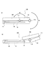
本発明を適用したスライド式携帯電話を示した図5、6において、携帯電話装置100は、第2のケース19、第1のケース180、第3のケース181、及びそれらを接続する第1のヒンジ170、第2のヒンジ171からなる。
[Second Embodiment]
Next, the
5 and 6 showing a slide type mobile phone to which the present invention is applied, the
第2のケース19は、図5(b)に示すように、一面(図示では上面)側にユーザからの操作指示を受け付ける操作部11を備えている。図5(a)、及び図6(a)に示すように、第2のケース19の操作部11を有する面上の長手方向に沿って第1のケース180及び第3のケース181が重ねられる。
As shown in FIG. 5B, the
第1のケース180は、第2のケース19の操作部11から一端側を覆う大きさであり、図5(a)に示すように、第2のケース19上に位置する状態で表面(図示では上面)にサブ表示部121を備える。
第3のケース181は、第2のケース19の操作部11から一端側を覆う大きさであり、図5(a)に示すように、第2のケース19の上に重ねた状態で表面にカメラ15を備える。この第3のケース181は、一端部で第2のケース19の操作部11と反対側端部に対し第1のヒンジ170により回動自在に結合されるとともに、他端部で第1のケース180の一端部に対し第2のヒンジ171により回動自在に結合されている。
The
The
そして、第2のケース19と第1のケース180の両側部には、第3のケース181と反対側端部で互いをスライド自在に結合するためのスライドガイド溝40とスライドガイドピン41が備えられており、スライドガイドピン41をスライドガイド溝40に挿入してスライド自在に係合する。
The both sides of the
そして、携帯電話装置100は、図5(a)と図6(a)に示すような閉じた状態と、図5(b)と図6(b)に示すようにR1、R2方向に回動してスライド係合して開く状態の状態があり、第1のヒンジ170及び第2のヒンジ171の内部にある開閉検出部25により各状態を検知する。
Then, the
このように、第2の実施の形態の携帯電話装置100によれば、回動・スライドさせることにより、動画撮影の開始・終了を検出できるので、動画撮影後に編集モードを起動させ、フェードイン・フェードアウト等の特殊加工処理をユーザが行わなくても、自動的に加工処理される。
As described above, according to the
[第3の実施の形態]
第3の実施の形態に係る携帯電話装置200について説明する。携帯電話装置1と同様の構成については、同一符号を付して説明を省略する。
第3の実施の形態の携帯電話装置200は、図7及び、図8に示すように、カメラ15は第1のケース18側の第1のヒンジ170で回動可能に設置され、その第1のヒンジ170から屈曲して延び、第2のケース19に第2のヒンジ171に回動可能に設置されるカメラユニット150に備えられていてカメラ15の隣には暗所での動画撮影時に発光するLED(発光部材)151が備えられている。
そして、第1のケース18には、カメラユニット150の上半分部分1500を収納可能且つ通過可能とする切欠部1800が形成されている。
[Third Embodiment]
A
As shown in FIGS. 7 and 8, in the
The
従って、図7(a)及び図8(a)に示したように、第2のケース19及び第1のケース18を重ねた折り畳み状態において、カメラユニット150の上半分部分1500とその先端面のカメラ15及びLED150が第1のケース18の切欠部182内に収納状態となって、カメラ15及びLED150を保護できる。
そして、折り畳み状態から第1のケース18をカメラユニット150と一緒に第2のヒンジ171でR3の方向に回動させて第2のケース19に対し開き、図7(b)及び図8(b)に示したように、第2のケース19の延長上に第1のケース18及びカメラユニット150を位置させた状態にする。
Therefore, as shown in FIGS. 7A and 8A, in the folded state in which the
Then, from the folded state, the
次に、第1のケース18を手前に引き寄せるようにカメラユニット150の第1のヒンジ170でR3の方向に回動させるとともに、カメラユニット150を第2のケース19に対し第2のヒンジ171でR4の方向に回動させると、図7(c)及び図8(c)に示したように、第2のケース19の延長上の手前側に第1のケース18が位置した状態になると同時に、カメラユニット150の上半分部分1500が手前側に向いた状態になる。
これにより、使用者の方にメイン表示部120、カメラ15及びLED151が向いた状態になり、開閉検出部25が動画撮影モードを検出して、動画の撮影を開始する。
Next, the
Thereby, the
一方、第1のケース18を第2のケース19から離すようにしてカメラユニット150を第1のヒンジ170でR5方向に回動させ、図7(d)及び図8(d)に示したように、第2のケース19に対し乗り越えるようにして操作部11を有する面の裏面側に第1のケース18及びカメラユニット150を位置させた状態にすることで、カメラユニット150の上半分部分1500に設けたカメラ15及びLED151をサブ表示部121と同一方向に向ける。
これにより、開閉検出部25が再度検出し、一度動画撮影を終了させてファイル化した後、今度は天地逆にして再度動画撮影を開始する。
On the other hand, the
As a result, the open /
このように、第3の実施の形態の携帯電話装置200によれば、第1のヒンジ170、第2のヒンジ171を備えた二軸構造にすることにより、いずれかの方向にカメラ15を向けても動画撮影の開始・終了を検出できるので、動画撮影後に編集モードを起動させ、フェードイン・フェードアウト等の特殊加工処理をユーザが行わなくても、自動的に加工処理を施すことができる。
Thus, according to the
[第4の実施の形態]
第4の実施の形態に係る携帯電話装置300について説明する。携帯電話装置1と同様の構成については、同一符号を付して説明を省略する。
第4の実施の形態の携帯電話装置300は、図9及び図10に示すように、第2のケース19の長手方向に沿って第1のケース18が重ねられる。そして、第2のケース19及び第1のケース18は、その重ねられた状態の長手方向一端側において、カメラユニット150を介して互いに回動自在に組み付けられている。
[Fourth Embodiment]
A
As shown in FIGS. 9 and 10, the
第1のケース18は、第2のケース19を覆う大きさであり、第2のケース19に重なる面側にメイン表示部120を備え、その裏面側に、図9(b)に示すように、サブ表示部121を備えている。
カメラユニット150は、一端側において、図10に示したように、第1のケース18の端部に対し第1のヒンジ170によりR6の方向に回動自在に結合されるとともに、第2のケース19の端部に対し第2のヒンジ171によりR6の方向に回動自在に結合されている。
このカメラユニット150には、図9(b)に示すように、第1のヒンジ170、第2の171と反対側の先端面にカメラ15を備えている。そして、カメラユニット150の上面には、動画撮影時に静止画撮影を指示するためのシャッターボタン1100が備えられている。
The
As shown in FIG. 10, the
As shown in FIG. 9B, the
以上のような外観により、本携帯電話装置300の使用者は、図9(a)及び図10(a)に示される第2のケース19及び第1のケース18を重ねた折り畳み状態から、第2のケース19及び第1のケース18をカメラユニット150に対し第1のヒンジ170、第2のヒンジ171で上方と下方にそれぞれ回動させて、図9(b)及び図10(b)に示したように、第2のケース19及び第1のケース18を開くことで、開閉検出部25がこれを検出し、動画撮影を開始させることができる。この動画撮影時の保持状態は図9(c)に示したように、第2のケース19及び第1のケース18から前方に突出するカメラユニット150を片手の中指の上に置いて後側から親指をあてた状態となり、使用者はメイン表示部120をファインダー(モニター)として見ながら撮影する。
With the appearance as described above, the user of the
このように、第4の実施の形態の携帯電話装置300によれば、フェードイン等の加工処理を撮影後に施さなくても、使用者にとって保持しやすい状態で動画撮影を開始させることができる。また、動画撮影中であってもシャッターボタン1100の操作を検出することにより、その時点でキャプチャーされたフレーム画像を静止画として保存することもできる。
Thus, according to the
[第5の実施の形態]
第5の実施の形態に係る携帯電話装置400について図11、図12を用いて説明する。携帯電話装置1と同様の構成については、同一符号を付して説明を省略する。
第5の実施の形態の携帯電話装置400は、図11(b)に示すように、一面(図示では上面)側に操作部11を備えている。図11(a)及び図12(a)に示すように、第2のケース19の操作部11を有する面上の長手方向に沿って第1のケース18が重ねられる。
[Fifth Embodiment]
A
As shown in FIG. 11B, the
第1のケース18は、第2のケース19を覆う大きさであり、図11(a)及び図11(b)に示すように、第2のケース19上に位置する状態で表面(図示では上面)にメイン表示部120と操作部1101とを備えている。
カメラユニット150は、側面視ほぼ三角形をなしていて、図12(a)に示すように、表面にカメラ15及びLED151、集音マイク152を並べて備えている。このカメラユニット150は、カメラ15と反対側の端部において、図12に示すように、第2のケース19の長手方向一端部に対し第1のヒンジ170により回動自在に結合されている。
The
The
以上において、第2のケース19及び第1のケース18には、第2のケース19に対し操作部11を有する面に重なる第1のケース18を長手方向に沿ってスライド自在に組み付けるガイド溝112が設けられている。ガイド溝112は、第1のケース18を第2のケース19の操作部11の両側部に沿ってスライドさせるために設けられるものであり、このガイド溝112には係合する図略のスライドピンが設置される。
As described above, in the
このような構成において、第5の実施の形態では、図12(b)に示すように第2のケース19上に重ねられる第1のケース18をM1の方向に平行にスライドさせることにより、第2のケース19の端部に設けられたカメラユニット150がスライド動作する第1のケース18に係合してR7の方向に回転して開閉検出部25がこれを検出する。また、この検出により動画撮影の開始と、録音の開始を同時に行わせることができる。
In such a configuration, in the fifth embodiment, the
このように、第5の実施の形態の携帯電話装置400によれば、フェードイン等の加工処理を撮影後に施さなくても、使用者にとって保持しやすい状態で動画撮影を開始させることができる。また、集音マイク152を実装させることで、被写体側の音声を好適に録音することもできる。
As described above, according to the
[第6の実施の形態]
第6の実施の形態に係る携帯電話装置500について図13を用いて説明する。携帯電話装置1と同様の構成については、同一符号を付して説明を省略する。
第6の実施の形態の携帯電話装置500は、図13に示すように、第2のケース19の操作部11を有する面の長手方向に沿って第1のケース184が重ねられる。これら第2のケース19及び第1のケース184は、その重ねられた状態の長手方向一端側において、回転部113及びヒンジ17を介して互いに回動自在に組み付けられている。
[Sixth Embodiment]
A
As shown in FIG. 13, in the
第1のケース184は、第2のケース19を覆う大きさであり、図13(b)、図13(c)に示すように、その一面側にメイン表示部120を備えている。
また、第2のケース19の操作部11を有する面の反対側面には、図13(a)に示すように、カメラ15及びLED(発光部材)151が並べて備えられている。これらカメラ15及びLED151は、操作部11の一側方に離れた裏側に位置している。さらに、第2のケース19の一側面にはサイドスイッチ111が備えられている。このサイドスイッチ111は、カメラ15及びLED151に対し他側方に位置している。
The
Further, as shown in FIG. 13A, a
回転部113は、第2のケース19に対しカメラ15の光軸と同一軸線上を中心として操作部11の側方位置で回転自在に組み付けられている。この回転部113には、タッチセンサーとしての機能を有する操作部110を中心に備え、その回転軸と直角をなす線を中心とするヒンジ17により第1のケース184が長手方向一端部で回動自在に結合されている。
以上により、第2のケース19に対し第1のケース184が、回転部112を介してその回転の中心周りに操作部11を有する面に沿った方向を含む360度方向に旋回自在になっている。さらに、回転部113に対し第1のケース184が、ヒンジ17周りに180度方向に回動自在になっている。
The
As described above, the
このような構成において、第6の実施の形態では、図13(a)及び図13(b)に示したように、第2のケース19の操作部11を有する面側に、第1のケース184のメイン表示部120を有する面と反対側面を重ねた折り畳み状態にすると、使用者にとって第2のケース19のカメラ15が向こう側を向いて第1のケース184のメイン表示部120が手前側に向いた状態となる。即ち、デジタルカメラとして片手で持つと同じような使用状態となって、メイン表示部120をファインダー(モニター)として見ながらカメラ15による風景撮影や他人撮影の使用に適した状態になる。
そして、この状態から第2のケース19をヒンジ17周りに180度回動させてメイン表示部120をカメラ15と同じ側に向けて、片手で持った使用者の方にメイン表示部120及びカメラ15を向けることにより、自分撮影の使用に適した状態になる。また、テレビ電話としての使用にも適した状態になる。
そして、いずれの形態を取った場合でも開閉検出部25がこれを検出する。この場合、例えば、図13(a)の状態から一度図13(b)の状態に遷移させると、動画撮影を開始させ、図13(b)の状態から図13(c)の状態に遷移させることで、動画撮影を終了させると、直ちにメール送信等の動作を行うことができる。
In such a configuration, in the sixth embodiment, as shown in FIGS. 13A and 13B, the first case is provided on the surface side of the
Then, from this state, the
In any case, the open /
[第7の実施の形態]
次に、図14〜図16を参照して、第7の実施の形態の携帯電話装置1、100、200、300、400、及び、500における更に詳細な動作実施形態について説明する。なお第1の実施の形態と同じ機能を有する箇所は、同一符号を付し、説明は省略する。また、以下、携帯電話1に述べるが、上記第2の実施の形態以降の携帯電話装置100、200、300、400、及び、500も同様の回路構成とする。
[Seventh Embodiment]
Next, with reference to FIG. 14 to FIG. 16, a more detailed operation embodiment in the
図14は本実施の形態における携帯電話装置1の回路構成図である。同図において、携帯電話装置1は、音声処理部211、画像処理部212、通信処理部213を制御部21、動作履歴記憶部221、一時保存メモリ222、動画ファイルメモリ223を備える記憶部22、電源部23、通信部24、開閉検出部25、表示ドライバ26、電源回路27、操作部11、スピーカ13、マイク14、加速度センサ32及びカメラ15とからなる。
FIG. 14 is a circuit configuration diagram of the mobile phone device 1 according to the present embodiment. In the figure, the mobile phone device 1 includes a
制御部21には、不図示のCPU(Central Processing Unit)をコアとした、複数の処理チップを内蔵する。
The
音声処理部211は、集音マイク152、マイク14からA/D変換されて出力された動画撮影時の音声や通話音声を例えばAAC方式のデータに圧縮符号化して、集音マイク152から取得した音声については後述する動画圧縮符号化の際に同時に音声ファイルとして保存させる他、マイク14から取得した通話音声についてはQCELP形式のデータに圧縮符号化して、通信処理部213に出力する。また、音声処理部211は通信処理部213の制御に基づいてアンテナ16より受信されたCDMA方式の無線信号から、通信部24にて自機宛ての信号をフィルタリングし、その中で得られた圧縮符号化されたデータから音声信号へ復号化処理も行う。
The
画像処理部212は、動画撮影に際し、所定時間おき(例えば15FPS)に撮像素子30にて結像されて読み出され、DSP301にてサンプリングやデジタル化されたイメージデータについて、スルー画像表示の際は、RGBデータに変換して、表示ドライバ126に送出し、開閉検出部25からの制御信号や、センターキー110の操作検出に基づいて動画撮影が開始されると、スルー画像を表示しつつ、DSP301にてサンプリングやデジタル化されたイメージデータをYUV(422)の輝度色差信号に変換し、MPEG形式の動画ファイルをリアルタイムで生成する。
また、開閉検出部25からの制御信号や、センターキー110の操作検出に基づいて動画撮影終了の検出すると、リアルタイムで生成された動画ファイルを一旦クローズ処理して一時保存メモリ222に保存させ、撮影終了後に取得される動作履歴記憶部221の記憶内容に基づいて、先頭フレームから所定フレーム、もしくは所定フレームから最終フレームを抽出して、フェードイン、フェードアウトの加工処理を行って、再圧縮符号化する処理も行う。
At the time of moving image shooting, the
When the end of the moving image shooting is detected based on the control signal from the open /
通信処理部213は、ユーザが加入した通信サービス会社から得られた識別コードにしたがって、CDMA方式の無線信号から自機宛ての信号を取得するように通信部24を制御したり、無線通信の対象となるデータがパケットデータである場合には、その通信タイミングを制御する。
The
カメラ15は、レンズ31、撮像素子30に加え、RAMを備えるDSP301を備える。
The
記憶部22は、OS(Operating System)や各種動作プログラムなど、携帯電話装置1のシステム又は動作に係るプログラムや、動画・音声などの各種データを格納する他に、動作履歴記憶部221、一時保存メモリ222、及び、動画ファイルメモリ223を備える。
The
動作履歴記憶部221は、後述の動画撮影処理に際し、開閉検出部25からの制御信号の入力検出から、加速度センサ32の検知による開閉動作終了までの時間と、加速度センサ32により入力された、開閉の速度やタイミングを記憶する。
The operation
一時保存メモリ222は、上記画像処理部212にてリアルタイムに圧縮符号化され、撮影終了が検出されることによりクローズされる動画ファイルを一時保存するためのものである。
The
次に、携帯電話装置1におけるフェードインする加工処理について、図15に示すフローチャートを参照して説明する。ここで説明する各処理は、携帯電話装置1が行うステップS31〜ステップS56からなる。 Next, the processing for fading in the cellular phone device 1 will be described with reference to the flowchart shown in FIG. Each process described here includes steps S31 to S56 performed by the mobile phone device 1.
折り畳まれた状態である携帯電話装置1は、まずその状態において、サイドスイッチ111の押下を検知して、動画撮影モードに移行する。まずステップS31にて撮像素子30にて結像されるイメージを所定間隔(例えば15FPS)毎に1フレーム読み出し、ステップS32にて画像処理部212にてRGB形式に変換されステップS33にて表示ドライバ送出、展開される。
In the folded state, the cellular phone device 1 in the folded state first detects that the
この展開された画像は所定間隔で更新処理され、サブ表示部121にて表示されるが、これと同時にステップS35のおいて、第1のケース18がヒンジ17を中心として第2のケース19より開く動作があるか否かを、開閉検出部25から制御信号が入力されるか否かで判断する。
The developed image is updated at a predetermined interval and displayed on the
開閉検出部25から制御信号が入力されるまで、ステップS31からステップS34までの処理を繰り返すが、開閉検出部25から制御信号が入力されると、計測ステップとしてのステップS36にて、制御信号が入力されたタイミングから制御部21にてカウントが開始され、その時点での加速度センサ32からの情報を取得し、完全に第1のケース18が第2のケース19から開かれる(ヒンジ17を回動軸として、例えば、160度以上回動する)までの時間、及び加速度の変化の動作履歴記憶部221へ記録を開始する。そして、ステップS37において、完全に開かれた状態を検知するまで、上記の処理を継続する。
The processing from step S31 to step S34 is repeated until a control signal is input from the open /
ステップS37にて完全に開かれたと判断すると、ステップS38において動作履歴記憶部221への記録を終了させ、サブ表示部121にて表示されていたイメージをメイン表示部120に表示させる(第2の表示制御ステップ)。次に、ステップS39にて撮像素子30にて結像されるイメージを所定間隔(例えば15FPS)毎に1フレーム読み出し、このフレームのイメージを画像処理部212にて表示出力用にRGB形式に変換すると同時に、YUV形式に変換する。
If it is determined in step S37 that it has been completely opened, recording in the operation
ステップS39にてYUV形式に変換されたフレームイメージは、順次出力されるその後のフレームイメージとともに、ステップS40にてリアルタイムで圧縮符号化処理され、MPEG4形式に準拠した動画ファイルが作成される。作成された動画ファイルはステップS41にて順次一時保存メモリ222に蓄積され、ステップS42のセンターキー110の操作の検出、つまり撮影終了を検知するまで、ステップS43による撮り込みの継続が行われる。
The frame image converted into the YUV format in step S39 is compression-encoded in real time in step S40 together with the subsequent frame images that are sequentially output, and a moving image file that complies with the MPEG4 format is created. The created moving image file is sequentially accumulated in the
ステップS41にてセンターキー110の操作を検出すると、撮影終了と判断し、撮像素子30の処理を一旦停止させ、ステップS44にてそれまで一時保存メモリ222に蓄積されていた動画ファイルのクローズ処理を行う。このクローズ処理とは、詳細には、ファイルヘッダを作成し動画ファイルに添付する処理や、プロファイルデータ(撮影日時、撮影時間(開始時間、終了時間)、撮影場所、ファイル容量、撮影者)を書き込む処理を示す。
When the operation of the
クローズ処理が終了すると、ステップS45にて、動作履歴記憶部221より、ヒンジ17を介した第1のケース18と第2のケース19との回動開始から終了までの時間と、加速度の変移を読み出す。そして、ステップS46にて一時保存メモリ222に保存された動画ファイルを展開し、ステップS47にて上記の回動開始から終了までの時間と、加速度の変移とに基づいて、動画ファイルの先頭フレームから所定フレームにフェードイン加工処理する。
When the closing process ends, in step S45, the operation
この加工処理とは、具体的には回動開始から回動終了までの時間が比較的短い場合と長い場合とで、加工処理を施すフレーム数に差を設ける処理を示し、長いケースの方が囲う処理を施すフレーム数が多くなるようにする。また加速度の変移については、単位時間あたりの速度変移が大きければ大きい程、加工の度合いを大きくするよう処理する。 Specifically, this processing indicates a process in which a difference is made in the number of frames to be processed depending on whether the time from the start of rotation to the end of rotation is relatively short or long. Increase the number of frames to be enclosed. As for the change in acceleration, the larger the speed change per unit time, the greater the degree of processing.
加工処理が完了すると、この加工処理された動画ファイルについて、ステップS48にて再生指示の検出の有無を判断する。再生指示を検出した場合、ステップS49にて加工処理された動画ファイルを再生するが、再生指示が検出されなかった場合は、ステップS50にてこの加工処理された動画ファイルの保存指示の有無を判断する。保存指示がされると、ステップS51にて展開され加工処理された動画ファイルについて、圧縮符号化処理を施し、ステップS52にて動画ファイルメモリ223に保存して、本処理を終了する。
When the processing is completed, it is determined in step S48 whether or not a reproduction instruction has been detected for the processed moving image file. If a playback instruction is detected, the video file processed in step S49 is played back. If no playback instruction is detected, it is determined in step S50 whether there is an instruction to save the processed video file. To do. When a save instruction is given, the moving image file expanded and processed in step S51 is subjected to compression encoding processing, saved in the moving
一方、ステップS50において保存が指示され無い場合、ステップS53にて加工処理していないオリジナルの動画ファイルの保存指示の有無を判断する。保存指示がされると、ステップS54にて加工処理された動画ファイルは破棄し、ステップS55にてオリジナルの動画ファイルを動画ファイルメモリ223に保存して、本処理を終了する。また、ステップS53にて保存が支持されなかった場合、一時保存メモリ222に記憶されているオリジナルの動画ファイルも破棄(クリア)する。またこのとき、加工処理された動画ファイルも破棄し、本処理を終了する。
On the other hand, if no saving is instructed in step S50, it is determined in step S53 whether or not there is an instruction to save the original moving image file that has not been processed. When the save instruction is given, the moving image file processed in step S54 is discarded, the original moving image file is saved in the moving
次に、携帯電話装置1におけるフェードアウトする加工処理について、図16に示すフローチャートを参照して説明する。ここで説明する各処理は、携帯電話装置1が行うステップS61〜ステップS73からなる。 Next, the processing for fading out in the cellular phone device 1 will be described with reference to the flowchart shown in FIG. Each process described here includes steps S61 to S73 performed by the mobile phone device 1.
本処理に関しては、動画撮影処理中、すなわち、図15におけるステップS39〜S41の処理を行っている時を本処理のスタート時点ととらえ、その後、開閉検出部25からの制御信号の入力、すなわち第1のケース18に第2のケース19を被せた(ヒンジ17を回動軸に第1のケース18と第2のケースとの角度を0度にした)ことを検出したか、センターキー110の操作を検出したかで撮影処理を終了させている。
Regarding this processing, during the moving image shooting processing, that is, when the processing of steps S39 to S41 in FIG. 15 is performed, the start time of this processing is considered. It is detected that the
まず、ステップS61において、開閉検出部25からの制御信号の入力の有無により、ユーザが携帯電話装置1を閉じる動作を行ったか否かを判断する。詳細には、上記したように、第1のケース18に第2のケース19を被せる動作を検出したか否かを開閉検出部25からの制御信号の入力の有無により判断する。
検出した場合は、撮影終了と判断し、撮像素子30の処理を一旦停止させ、それまで一時保存メモリ222に蓄積されていた動画ファイルのクローズ処理を行う。
First, in step S <b> 61, it is determined whether or not the user has performed an operation of closing the mobile phone device 1 based on whether or not a control signal is input from the open /
If it is detected, it is determined that shooting has been completed, the processing of the
このクローズ処理とは、詳細には、ファイルヘッダを作成し動画ファイルに添付する処理や、プロファイルデータ(撮影日時、撮影時間(開始時間、終了時間)、撮影場所、ファイル容量、撮影者)を書き込む処理を示す。 In detail, the close process is a process of creating a file header and attaching it to a movie file, and writing profile data (shooting date and time, shooting time (start time and end time), shooting location, file capacity, photographer). Indicates processing.
そして、ステップS63にて、ステップS62で制御信号が入力されたタイミングから制御部21にてカウントが開始され、その時点での加速度センサ32からの情報を取得し、完全に第1のケース18が第2のケース19に被さる(ヒンジ17を回動軸として、例えば、0度になる)までの時間、及び加速度の変化の動作履歴記憶部221へ記録を開始する。そして、ステップS64において、完全に被さった状態を検知するまで、上記の処理を継続する。
In step S63, the
ステップS64にて完全に被さったと判断すると、ステップS65において動作履歴記憶部221への記録を終了させ、次にステップS66にてこの動作履歴記憶部221より、ヒンジ17を介した第1のケース18と第2のケース19との回動開始から終了までの時間と、加速度の変移を読み出す。
If it is determined in step S64 that the cover has been completely covered, recording in the operation
そして、ステップS67にて一時保存メモリ222に保存された動画ファイルを展開し、ステップS68にて上記の回動開始から終了までの時間と、加速度の変移とに基づいて、動画ファイルの所定フレームから最終フレームにフェードアウト加工処理を施し、図15のステップS48の処理に移行する。
Then, in step S67, the moving image file stored in the
この加工処理とは、具体的には回動開始から回動終了までの時間が比較的短い場合と長い場合とで、加工処理を施すフレーム数に差を設ける処理を示し、長いケースの方が囲う処理を施すフレーム数が多くなるようにする。また加速度の変移については、単位時間あたりの速度変移が大きければ大きい程、加工の度合いを大きくするよう処理する。 Specifically, this processing indicates a process in which a difference is made in the number of frames to be processed depending on whether the time from the start of rotation to the end of rotation is relatively short or long. Increase the number of frames to be enclosed. As for the change in acceleration, the larger the speed change per unit time, the greater the degree of processing.
一方、ステップS61にて閉じる動作を検出せずに、センターキー110の操作を検出すると、撮影終了と判断し、ステップS70にて撮像素子30の処理を一旦停止させ、それまで一時保存メモリ222に蓄積されていた動画ファイルのクローズ処理を行う。開閉検出部25からの制御信号の入力、及び、センターキー110の操作を検出しなかった場合は、撮影処理を継続する。
On the other hand, if the operation of the
ステップS70にてクローズ処理され、一時保存メモリ222に蓄積された動画ファイルは、ステップS71にて保存指示が検出されたか否か判断し、保存指示が検出されるとステップS72にてこの動画ファイルを動画ファイルメモリ223に保存して、本処理を終了する。また、保存指示が検出されなかった場合は、ステップS73にて一時保存メモリ222に記憶されている動画ファイルを破棄し、本処理を終了する。
The moving image file closed in step S70 and stored in the
このように、第7の実施の形態においては、開閉検出部25、及び、加速度センサ32から出力される情報信号を撮影終了まで保存する動作履歴記憶部221を備える構成としている。したがって、第1のケース18と第2のケース19との回動に関する動作を記憶する構成としているので、複数の動画ファイルを加工する際にも、この動作履歴記憶部221の内容を参照して手軽に加工処理を施すことが可能になる。
As described above, the seventh embodiment is configured to include the open /
1、100、200、300、400、500 携帯電話装置(動画撮影装置)
11 操作部
1100 シャッターボタン
1101 操作部
110 センターキー
111 サイドスイッチ
112 ガイド溝
113 回転部
12 表示部
120 メイン表示部(第1の表示手段)
121 サブ表示部(第2の表示手段)
126 表示ドライバ
13 スピーカ
14 マイク
15 カメラ(撮像手段)
150 カメラユニット
151 LED
152 集音マイク
153 ドライバ
1500 上半分部分
16 アンテナ
17 ヒンジ
170 第1のヒンジ
171 第2のヒンジ
18、180、184 第1のケース
181 第3のケース
182 切欠部
19 第2のケース
21 制御部(動画取得手段、取得制御手段、計測手段、加工処理手段、第2の検出手段、第1、2の表示制御手段)
211 音声処理部
212 画像処理部
213 通信処理部
22 記憶部
221 動作履歴記憶部
222 一時保存メモリ(第1の記憶手段)
223 動画ファイルメモリ(第2の記憶手段)
23 電源部
24 通信部
25 開閉検出部(第1の検出手段)
26 表示ドライバ
27 電源回路
28 ACアダプタ
29 充電池
30 撮像素子
301 DSP
31 レンズ
32 加速度センサ
40 スライドガイド溝
41 スライドガイドピン
1, 100, 200, 300, 400, 500 Mobile phone device (moving image shooting device)
11
121 Sub display section (second display means)
126
150
152
211
223 video file memory (second storage means)
23
26
31
Claims (10)
撮像手段と、
前記撮像手段を連続的に駆動させることにより動画ファイルを取得する動画取得手段と、
前記接続部を介した前記第1のケースと前記第2のケースとの相対的な位置関係の変化を検出する第1の検出手段と、
前記第1の検出手段による検出に基づいて、前記動画取得手段による動画ファイルの取得の開始若しくは終了を制御する取得制御手段と、
前記第1のケースと前記第2のケースとの相対的な位置関係の変化の開始から終了までの時間を計測する計測手段と、
前記計測手段によって計測された時間に基づいて、前記動画取得手段によって取得された動画ファイルに加工処理を施す加工処理手段と、
を備えたことを特徴とする動画撮影装置。 A first case and a second case, which are pivotally connected to each other via a connecting portion;
Imaging means;
Moving image acquisition means for acquiring a moving image file by continuously driving the imaging means;
First detection means for detecting a change in a relative positional relationship between the first case and the second case via the connection portion;
An acquisition control means for controlling the start or end of acquisition of a moving image file by the moving image acquisition means based on detection by the first detection means;
Measuring means for measuring the time from the start to the end of a change in the relative positional relationship between the first case and the second case;
Based on the time measured by the measuring means, a processing means for processing the moving image file acquired by the moving image acquiring means,
A video shooting device comprising:
前記加工処理手段は、前記第2の検出手段によって検出された度合いに基づいて、前記動画取得手段によって取得された動画ファイルに加工処理を施すことを特徴とする請求項1に記載の動画撮影装置。 A second detection means for detecting a degree of positional relationship per unit time from the start to the end of a change in relative positional relationship between the first case and the second case;
2. The moving image photographing apparatus according to claim 1 , wherein the processing unit performs processing on the moving image file acquired by the moving image acquiring unit based on the degree detected by the second detecting unit. .
前記指示手段による動画取得を終了、又は前記第1の検出手段による検出によって動画取得を終了に応じて前記加工処理手段を制御する制御手段と、
を更に備えることを特徴とする請求項1〜4のいずれか一項に記載の動画撮影装置。 Instruction means for instructing the end of moving image acquisition by the moving image acquisition means;
Control means for controlling the processing means in accordance with the end of moving image acquisition by the instruction means or the end of moving image acquisition by detection by the first detection means;
The moving image photographing apparatus according to claim 1, further comprising:
第2の表示手段と、
前記撮像手段を連続的に駆動させることによるイメージデータを元に前記第2の表示手段に表示させる第1の表示制御手段と、
前記第1の検出手段によって、前記第1のケースと第2のケースとの相対的な位置関係の変化を検出することにより、前記撮像手段を連続的に駆動させることによるイメージデータを元に前記第1の表示手段に表示させるよう制御する第2の表示制御手段と、
を更に備えたことを特徴とする請求項1〜5のいずれか一項に記載の動画撮影装置。 First display means;
A second display means;
First display control means for displaying on the second display means based on image data obtained by continuously driving the imaging means;
The first detection means detects the change in the relative positional relationship between the first case and the second case, and based on image data obtained by continuously driving the imaging means. Second display control means for controlling to display on the first display means;
The moving image photographing apparatus according to claim 1, further comprising:
前記加工処理手段によって加工処理された動画ファイルを保持する第2の記憶手段と、
を更に備えることを特徴とする請求項1〜6のいずれか一項に記載の動画撮影装置。 First storage means for holding a video file acquired by the video acquisition means;
Second storage means for holding a moving image file processed by the processing means;
The moving image shooting apparatus according to claim 1, further comprising:
撮像部を連続的に駆動させることにより動画ファイルを取得する動画取得ステップと、 A moving image acquisition step of acquiring a moving image file by continuously driving the imaging unit;
前記接続部を介した前記第1のケースと第2のケースとの位置関係の変化を検出する検出ステップと、 A detection step of detecting a change in the positional relationship between the first case and the second case via the connecting portion;
前記検出ステップによる検出結果に基づいて、前記動画取得ステップによる動画ファイル取得の開始若しくは終了を制御する取得制御ステップと、 Based on the detection result of the detection step, an acquisition control step for controlling the start or end of moving image file acquisition by the moving image acquisition step;
前記第1のケースと前記第2のケースとの相対的な位置関係の変化の開始から終了までの時間を計測する計測ステップと、 A measurement step of measuring a time from the start to the end of a change in the relative positional relationship between the first case and the second case;
前記計測ステップにて計測された時間に基づいて、前記動画取得ステップにて取得された動画ファイルに加工処理を施す加工処理ステップと、 Based on the time measured in the measurement step, a processing step for performing processing on the video file acquired in the video acquisition step;
を含むことを特徴とする動画撮影制御方法。 A moving image shooting control method comprising:
前記撮像部を連続的に駆動させることにより動画ファイルを取得する動画取得手段、 Movie acquisition means for acquiring a movie file by continuously driving the imaging unit,
前記接続部を介した前記第1のケースと前記第2のケースとの位置関係の変化を検出する検出手段、 Detecting means for detecting a change in the positional relationship between the first case and the second case via the connecting portion;
前記検出手段による検出に基づいて、前記動画取得手段による動画ファイルの取得の開始若しくは終了を制御する取得制御手段、 An acquisition control means for controlling the start or end of the acquisition of the moving image file by the moving image acquisition means based on the detection by the detection means;
前記第1のケースと前記第2のケースとの相対的な位置関係の変化の開始から終了までの時間を計測する計測手段、 Measuring means for measuring a time from the start to the end of a change in relative positional relationship between the first case and the second case;
前記計測手段によって計測された時間に基づいて、前記動画取得手段によって取得された動画ファイルに加工処理を施す加工処理手段、 Processing means for processing the moving image file acquired by the moving image acquisition means based on the time measured by the measuring means;
として機能させることを特徴とする動画撮影制御プログラム。 A video shooting control program that functions as a computer program.
Priority Applications (1)
| Application Number | Priority Date | Filing Date | Title |
|---|---|---|---|
| JP2005065728A JP4552699B2 (en) | 2004-04-05 | 2005-03-09 | Movie shooting device, movie shooting control method, and movie shooting control program |
Applications Claiming Priority (2)
| Application Number | Priority Date | Filing Date | Title |
|---|---|---|---|
| JP2004111057 | 2004-04-05 | ||
| JP2005065728A JP4552699B2 (en) | 2004-04-05 | 2005-03-09 | Movie shooting device, movie shooting control method, and movie shooting control program |
Publications (3)
| Publication Number | Publication Date |
|---|---|
| JP2005323336A JP2005323336A (en) | 2005-11-17 |
| JP2005323336A5 JP2005323336A5 (en) | 2008-04-24 |
| JP4552699B2 true JP4552699B2 (en) | 2010-09-29 |
Family
ID=35470234
Family Applications (1)
| Application Number | Title | Priority Date | Filing Date |
|---|---|---|---|
| JP2005065728A Expired - Fee Related JP4552699B2 (en) | 2004-04-05 | 2005-03-09 | Movie shooting device, movie shooting control method, and movie shooting control program |
Country Status (1)
| Country | Link |
|---|---|
| JP (1) | JP4552699B2 (en) |
Families Citing this family (5)
| Publication number | Priority date | Publication date | Assignee | Title |
|---|---|---|---|---|
| JP4898704B2 (en) * | 2005-12-12 | 2012-03-21 | 淳大 上田 | Data sampling device for diagnostic imaging and imaging adapter used for the device |
| JP2012124608A (en) * | 2010-12-06 | 2012-06-28 | Olympus Imaging Corp | Camera |
| CN105745573B (en) | 2014-02-07 | 2018-09-25 | 松下知识产权经营株式会社 | Rotation detection device, the camera for having the rotation detection device and the photographic device for having the camera |
| US9749510B2 (en) | 2014-12-25 | 2017-08-29 | Panasonic Intellectual Property Management Co., Ltd. | Imaging unit and imaging apparatus |
| JP6707948B2 (en) * | 2016-03-29 | 2020-06-10 | いすゞ自動車株式会社 | Drive recorder |
Citations (5)
| Publication number | Priority date | Publication date | Assignee | Title |
|---|---|---|---|---|
| JP2002125032A (en) * | 2001-08-16 | 2002-04-26 | Hitachi Ltd | Video phone |
| JP2003244619A (en) * | 2002-02-18 | 2003-08-29 | Nikon Gijutsu Kobo:Kk | Digital camera |
| JP2004228767A (en) * | 2003-01-21 | 2004-08-12 | Kyocera Corp | Folding portable terminal |
| JP2004274319A (en) * | 2003-03-07 | 2004-09-30 | Mitsubishi Electric Corp | Mobile phone |
| JP2004312389A (en) * | 2003-04-07 | 2004-11-04 | Sony Ericsson Mobilecommunications Japan Inc | Mobile communication terminal device |
-
2005
- 2005-03-09 JP JP2005065728A patent/JP4552699B2/en not_active Expired - Fee Related
Patent Citations (5)
| Publication number | Priority date | Publication date | Assignee | Title |
|---|---|---|---|---|
| JP2002125032A (en) * | 2001-08-16 | 2002-04-26 | Hitachi Ltd | Video phone |
| JP2003244619A (en) * | 2002-02-18 | 2003-08-29 | Nikon Gijutsu Kobo:Kk | Digital camera |
| JP2004228767A (en) * | 2003-01-21 | 2004-08-12 | Kyocera Corp | Folding portable terminal |
| JP2004274319A (en) * | 2003-03-07 | 2004-09-30 | Mitsubishi Electric Corp | Mobile phone |
| JP2004312389A (en) * | 2003-04-07 | 2004-11-04 | Sony Ericsson Mobilecommunications Japan Inc | Mobile communication terminal device |
Also Published As
| Publication number | Publication date |
|---|---|
| JP2005323336A (en) | 2005-11-17 |
Similar Documents
| Publication | Publication Date | Title |
|---|---|---|
| KR100798187B1 (en) | Moving image capture device, moving image capture control method, and recording medium for recording moving image capture control program | |
| JP6134803B2 (en) | Video recording apparatus and camera function control program | |
| JP4802077B2 (en) | Portable device | |
| CN100527820C (en) | Video playback device and playback method | |
| CN100496064C (en) | Image capturing apparatus | |
| US20080063392A1 (en) | Image photography apparatus | |
| JP4552699B2 (en) | Movie shooting device, movie shooting control method, and movie shooting control program | |
| JP2007005985A (en) | Imaging apparatus, program, information terminal, and information communication system | |
| JP2008085865A (en) | Mobile device | |
| JP3929704B2 (en) | Imaging device with communication function | |
| US20090109331A1 (en) | Portable device and imaging device | |
| JP6314272B2 (en) | Video recording apparatus and video recording method | |
| US20050018050A1 (en) | Wireless communication device, dynamic image preparation method and dynamic image preparation program | |
| JP4258098B2 (en) | Electronic camera | |
| JP3813892B2 (en) | Mobile phone equipment | |
| JP4453692B2 (en) | Imaging device | |
| JP3994959B2 (en) | Portable electronic device and portable telephone | |
| KR101111539B1 (en) | Recording/reproducing apparatus and recording/reproducing apparatus control method | |
| JP2004282605A (en) | Mobile electronic apparatus system, mobile electronic apparatus, charging control method for mobile electronic apparatus, and program | |
| JP3873963B2 (en) | Image display device, image display control method, and image display control program | |
| JP2003249986A (en) | Image pickup and communication device | |
| JP2002344802A (en) | Camera and method for changing its mode | |
| JP4085320B2 (en) | Digital camera | |
| JP5245493B2 (en) | Imaging apparatus, imaging apparatus control program, and imaging control method | |
| JP5672330B2 (en) | Imaging apparatus, imaging apparatus control program, and imaging control method |
Legal Events
| Date | Code | Title | Description |
|---|---|---|---|
| A521 | Request for written amendment filed |
Free format text: JAPANESE INTERMEDIATE CODE: A523 Effective date: 20080306 |
|
| A621 | Written request for application examination |
Free format text: JAPANESE INTERMEDIATE CODE: A621 Effective date: 20080306 |
|
| A131 | Notification of reasons for refusal |
Free format text: JAPANESE INTERMEDIATE CODE: A131 Effective date: 20100330 |
|
| A521 | Request for written amendment filed |
Free format text: JAPANESE INTERMEDIATE CODE: A523 Effective date: 20100531 |
|
| TRDD | Decision of grant or rejection written | ||
| A01 | Written decision to grant a patent or to grant a registration (utility model) |
Free format text: JAPANESE INTERMEDIATE CODE: A01 Effective date: 20100622 |
|
| A01 | Written decision to grant a patent or to grant a registration (utility model) |
Free format text: JAPANESE INTERMEDIATE CODE: A01 |
|
| A61 | First payment of annual fees (during grant procedure) |
Free format text: JAPANESE INTERMEDIATE CODE: A61 Effective date: 20100705 |
|
| FPAY | Renewal fee payment (event date is renewal date of database) |
Free format text: PAYMENT UNTIL: 20130723 Year of fee payment: 3 |
|
| R150 | Certificate of patent or registration of utility model |
Free format text: JAPANESE INTERMEDIATE CODE: R150 |
|
| LAPS | Cancellation because of no payment of annual fees |