JP4541476B2 - Multi-image display system and multi-image display method - Google Patents
Multi-image display system and multi-image display method Download PDFInfo
- Publication number
- JP4541476B2 JP4541476B2 JP37143099A JP37143099A JP4541476B2 JP 4541476 B2 JP4541476 B2 JP 4541476B2 JP 37143099 A JP37143099 A JP 37143099A JP 37143099 A JP37143099 A JP 37143099A JP 4541476 B2 JP4541476 B2 JP 4541476B2
- Authority
- JP
- Japan
- Prior art keywords
- cursor
- screen
- image
- image source
- control
- Prior art date
- Legal status (The legal status is an assumption and is not a legal conclusion. Google has not performed a legal analysis and makes no representation as to the accuracy of the status listed.)
- Expired - Fee Related
Links
Images


Classifications
-
- H—ELECTRICITY
- H04—ELECTRIC COMMUNICATION TECHNIQUE
- H04N—PICTORIAL COMMUNICATION, e.g. TELEVISION
- H04N21/00—Selective content distribution, e.g. interactive television or video on demand [VOD]
- H04N21/40—Client devices specifically adapted for the reception of or interaction with content, e.g. set-top-box [STB]; Operations thereof
- H04N21/47—End-user applications
-
- G—PHYSICS
- G09—EDUCATION; CRYPTOGRAPHY; DISPLAY; ADVERTISING; SEALS
- G09G—ARRANGEMENTS OR CIRCUITS FOR CONTROL OF INDICATING DEVICES USING STATIC MEANS TO PRESENT VARIABLE INFORMATION
- G09G5/00—Control arrangements or circuits for visual indicators common to cathode-ray tube indicators and other visual indicators
- G09G5/08—Cursor circuits
-
- G—PHYSICS
- G09—EDUCATION; CRYPTOGRAPHY; DISPLAY; ADVERTISING; SEALS
- G09G—ARRANGEMENTS OR CIRCUITS FOR CONTROL OF INDICATING DEVICES USING STATIC MEANS TO PRESENT VARIABLE INFORMATION
- G09G5/00—Control arrangements or circuits for visual indicators common to cathode-ray tube indicators and other visual indicators
- G09G5/14—Display of multiple viewports
-
- G—PHYSICS
- G09—EDUCATION; CRYPTOGRAPHY; DISPLAY; ADVERTISING; SEALS
- G09G—ARRANGEMENTS OR CIRCUITS FOR CONTROL OF INDICATING DEVICES USING STATIC MEANS TO PRESENT VARIABLE INFORMATION
- G09G5/00—Control arrangements or circuits for visual indicators common to cathode-ray tube indicators and other visual indicators
- G09G5/36—Control arrangements or circuits for visual indicators common to cathode-ray tube indicators and other visual indicators characterised by the display of a graphic pattern, e.g. using an all-points-addressable [APA] memory
- G09G5/363—Graphics controllers
-
- G—PHYSICS
- G09—EDUCATION; CRYPTOGRAPHY; DISPLAY; ADVERTISING; SEALS
- G09G—ARRANGEMENTS OR CIRCUITS FOR CONTROL OF INDICATING DEVICES USING STATIC MEANS TO PRESENT VARIABLE INFORMATION
- G09G5/00—Control arrangements or circuits for visual indicators common to cathode-ray tube indicators and other visual indicators
- G09G5/36—Control arrangements or circuits for visual indicators common to cathode-ray tube indicators and other visual indicators characterised by the display of a graphic pattern, e.g. using an all-points-addressable [APA] memory
- G09G5/39—Control of the bit-mapped memory
- G09G5/393—Arrangements for updating the contents of the bit-mapped memory
-
- H—ELECTRICITY
- H04—ELECTRIC COMMUNICATION TECHNIQUE
- H04N—PICTORIAL COMMUNICATION, e.g. TELEVISION
- H04N21/00—Selective content distribution, e.g. interactive television or video on demand [VOD]
- H04N21/40—Client devices specifically adapted for the reception of or interaction with content, e.g. set-top-box [STB]; Operations thereof
- H04N21/43—Processing of content or additional data, e.g. demultiplexing additional data from a digital video stream; Elementary client operations, e.g. monitoring of home network or synchronising decoder's clock; Client middleware
- H04N21/431—Generation of visual interfaces for content selection or interaction; Content or additional data rendering
- H04N21/4312—Generation of visual interfaces for content selection or interaction; Content or additional data rendering involving specific graphical features, e.g. screen layout, special fonts or colors, blinking icons, highlights or animations
- H04N21/4316—Generation of visual interfaces for content selection or interaction; Content or additional data rendering involving specific graphical features, e.g. screen layout, special fonts or colors, blinking icons, highlights or animations for displaying supplemental content in a region of the screen, e.g. an advertisement in a separate window
-
- H—ELECTRICITY
- H04—ELECTRIC COMMUNICATION TECHNIQUE
- H04N—PICTORIAL COMMUNICATION, e.g. TELEVISION
- H04N21/00—Selective content distribution, e.g. interactive television or video on demand [VOD]
- H04N21/40—Client devices specifically adapted for the reception of or interaction with content, e.g. set-top-box [STB]; Operations thereof
- H04N21/43—Processing of content or additional data, e.g. demultiplexing additional data from a digital video stream; Elementary client operations, e.g. monitoring of home network or synchronising decoder's clock; Client middleware
- H04N21/436—Interfacing a local distribution network, e.g. communicating with another STB or one or more peripheral devices inside the home
- H04N21/4363—Adapting the video or multiplex stream to a specific local network, e.g. a IEEE 1394 or Bluetooth® network
- H04N21/43632—Adapting the video or multiplex stream to a specific local network, e.g. a IEEE 1394 or Bluetooth® network involving a wired protocol, e.g. IEEE 1394
-
- H—ELECTRICITY
- H04—ELECTRIC COMMUNICATION TECHNIQUE
- H04N—PICTORIAL COMMUNICATION, e.g. TELEVISION
- H04N21/00—Selective content distribution, e.g. interactive television or video on demand [VOD]
- H04N21/40—Client devices specifically adapted for the reception of or interaction with content, e.g. set-top-box [STB]; Operations thereof
- H04N21/43—Processing of content or additional data, e.g. demultiplexing additional data from a digital video stream; Elementary client operations, e.g. monitoring of home network or synchronising decoder's clock; Client middleware
- H04N21/443—OS processes, e.g. booting an STB, implementing a Java virtual machine in an STB or power management in an STB
- H04N21/4438—Window management, e.g. event handling following interaction with the user interface
-
- G—PHYSICS
- G09—EDUCATION; CRYPTOGRAPHY; DISPLAY; ADVERTISING; SEALS
- G09G—ARRANGEMENTS OR CIRCUITS FOR CONTROL OF INDICATING DEVICES USING STATIC MEANS TO PRESENT VARIABLE INFORMATION
- G09G2340/00—Aspects of display data processing
- G09G2340/02—Handling of images in compressed format, e.g. JPEG, MPEG
-
- G—PHYSICS
- G09—EDUCATION; CRYPTOGRAPHY; DISPLAY; ADVERTISING; SEALS
- G09G—ARRANGEMENTS OR CIRCUITS FOR CONTROL OF INDICATING DEVICES USING STATIC MEANS TO PRESENT VARIABLE INFORMATION
- G09G2340/00—Aspects of display data processing
- G09G2340/04—Changes in size, position or resolution of an image
- G09G2340/0407—Resolution change, inclusive of the use of different resolutions for different screen areas
-
- G—PHYSICS
- G09—EDUCATION; CRYPTOGRAPHY; DISPLAY; ADVERTISING; SEALS
- G09G—ARRANGEMENTS OR CIRCUITS FOR CONTROL OF INDICATING DEVICES USING STATIC MEANS TO PRESENT VARIABLE INFORMATION
- G09G2340/00—Aspects of display data processing
- G09G2340/12—Overlay of images, i.e. displayed pixel being the result of switching between the corresponding input pixels
- G09G2340/125—Overlay of images, i.e. displayed pixel being the result of switching between the corresponding input pixels wherein one of the images is motion video
-
- G—PHYSICS
- G09—EDUCATION; CRYPTOGRAPHY; DISPLAY; ADVERTISING; SEALS
- G09G—ARRANGEMENTS OR CIRCUITS FOR CONTROL OF INDICATING DEVICES USING STATIC MEANS TO PRESENT VARIABLE INFORMATION
- G09G2370/00—Aspects of data communication
- G09G2370/02—Networking aspects
- G09G2370/027—Arrangements and methods specific for the display of internet documents
-
- H—ELECTRICITY
- H04—ELECTRIC COMMUNICATION TECHNIQUE
- H04N—PICTORIAL COMMUNICATION, e.g. TELEVISION
- H04N21/00—Selective content distribution, e.g. interactive television or video on demand [VOD]
- H04N21/40—Client devices specifically adapted for the reception of or interaction with content, e.g. set-top-box [STB]; Operations thereof
- H04N21/47—End-user applications
- H04N21/485—End-user interface for client configuration
- H04N21/4858—End-user interface for client configuration for modifying screen layout parameters, e.g. fonts, size of the windows
Description
【0001】
【発明の属する技術分野】
本発明は、複数の画像ソースからそれぞれ入力された画像データを1つの表示装置に同時に表示することが可能なマルチ画像表示システムおよびマルチ画像表示方法に関する。
【0002】
【従来の技術】
近年、DTV(デジタルテレビ)、DVD(デジタルビデオディスクなど)、PC(パーソナルコンピュータ)などから供給する画像データを大型の表示装置例えば液晶プロジェクタやプラズマディスプレイに多画面で表示させることが増している。これを受けて将来、家庭においては、この大型の表示装置をマルチメディアの中心デバイスと位置付け、各映像メディアを表示デバイスに統合表示した形態での用途が望まれている。このような背景から、画像表示システムには、複数の画像を同時に表示することができる機能が必要である。そして、現在提案されている大型表示装置では、接続された異なる複数のメディアから供給された各画像データを該表示装置の画面上に任意にレイアウトして表示する機能を設け、この機能により複数の画像データを同時に表示する。すなわち、大型表示装置をマルチ画面ビュワーとして用いることによってマルチ画像表示システムを構築している。
【0003】
【発明が解決しようとする課題】
しかしながら、上述した従来のマルチ画像表示システムでは、画面上に表示される画像データがPCの画像データであるときには、この表示する画像データの編集、切り替えに関する操作をPC側のカーソルまたはマウスによる操作に移行させる必要がある。これは、カーソル発生手段およびアプリケーション制御がPC内部に設けられているためである。インタラクティブ形式な統合デジィタル放送システムなどの放送画像をマルチ画面表示の一部としてレイアウト表示している場合には、放送業者が意図した解像度まで一度戻した後にこの放送画面の切り替えを行うための切り替えアクションをしなければならない。これは、現在予定されている放送画像に関しては放送事業者が意図する解像度でメニュー画面を構成するようになっており、ユーザがマルチ表示のための解像度変換を行うと、インタラクティブな選択を行うことができないなどの操作上の不具合が発生する可能性があるからである。その結果、従来のマルチ画像表示システムでは、大型表示装置を制御の中心として各メディアを一元的にコントロールすることはできない。すなわち、ユーザインタフェースは操作性が悪いユーザインターフェイスとなる。
【0004】
本発明の目的は、マルチ画面上の各画像に対する操作を一元的に行うことができるマルチ画像表示システムおよびマルチ画像表示方法を提供することにある。
【0005】
【課題を解決するための手段】
本発明は、上記目的を達成するため、接続された複数の画像ソースから入力される複数の画像を表示装置にマルチ画面で表示するマルチ画像表示システムにおいて、接続された各画像ソースの種別を判別する画像ソース判別手段と、前記マルチ画面での入力操作を行うためのマルチ画面制御カーソルを生成して前記マルチ画面に表示し、該マルチ画面制御カーソルの操作に関する制御を行うカーソル制御手段と、前記マルチ画面における前記マルチ画面制御カーソルの表示位置を識別する表示位置識別手段とを備え、前記画像ソース判別手段により、前記マルチ画面制御カーソルの表示位置に対応する画像ソースが、カーソル生成機能を有する画像ソースであると判別された場合に、前記カーソル制御手段は、前記マルチ画面制御カーソルを非表示にして、前記カーソル生成機能を有する画像ソースにカーソルを生成させる制御を行うことを特徴とする。
【0006】
本発明は、上記目的を達成するため、接続された複数の画像ソースから入力される複数の画像を表示装置にマルチ画面で表示するマルチ画像表示システムにおいて、接続された各画像ソースの種別を判別する画像ソース判別手段と、前記マルチ画面での入力操作を行うためのマルチ画面制御カーソルを生成して前記マルチ画面に表示し、該マルチ画面制御カーソルの操作に関する制御を行うカーソル制御手段と、前記マルチ画面における前記マルチ画面制御カーソルの表示位置を識別する表示位置識別手段とを備え、前記画像ソース判別手段により、前記マルチ画面制御カーソルの表示位置に対応する画像ソースが、カーソルの属性情報が所定の記述言語で記述された画像ソースであると判別された場合に、前記カーソル制御手段は、前記マルチ画面制御カーソルを非表示にして、前記所定の記述言語で記述されたカーソルの属性情報に基づいて、前記所定の記述言語専用カーソルを表示する制御を行うことを特徴とする。
【0007】
また、本発明は、上記目的を達成するため、マルチ画像表示方法を提供する。
【0025】
【発明の実施の形態】
以下に本発明の実施の形態について図を参照しながら説明する。
【0026】
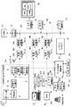
図1は本発明のマルチ画像表示システムの実施の一形態の構成を示すブロック図である。
【0027】
マルチ画像表示システムは、図1に示すように、互いに独立した3つの画像ソース(ISDB対応DTV受信部1a,PC1b,DVD1c)から供給された画像を表示デバイス16上にマルチ画面表示形態で同時に表示する。
【0028】
ここで、ISDB対応DTV受信部(以下、受信部という)1aの説明の前に、ISDBについて説明する。デジタル技術の発展に伴い放送界では、放送信号を含む各情報をデジタル化したインタラクティブ形式の統合デジタル放送システム(ISDB;Integrated Services Digital Broadcasting)が研究、開発されている。具体的には、このISDBシステムとは、現行の放送信号(標準テレビジョン信号、ハイビジョン信号)を始めとして、ソフトウェアやファクシミリなどのデータ、さらには音声、図形、画像などのマルチメディア情報をそれぞれデジタル化し、それらを統合多重化した上で、伝送形態に合致した変調処理を施して送信する放送システムをいう。放送信号を含む各種情報を多重化する場合には、これらの情報の他に受信側での制御情報として使用する付加情報を同時に統合多重化して送信することが可能である。統合化されたISDB用放送信号(デジタル信号)は、地上波、衛星波、光ケーブルなどを利用して送信される。受信端末側では、統合化されたISDB用放送信号を受信して目的の信号を弁別し、それをモニタに表示して通常のテレビ放送として楽しむことができることは勿論、記録手段を用いて記録、保存したり、他の端末に転送したりすることができる。さらに受信した付加情報を利用すれば、モニタ制御、記録制御、さらにはモニタされた画像に対する加工制御など、ユーザの好みに応じて受信情報を利用することができる。すなわち、インタラクティブ(対話形式)な放送システムを構築することができる。
【0029】
受信部1aは、チューナー部2を有し、チューナー部2は、統合化されたISDB用放送信号(デジタル信号)を地上波、衛星波、光ケーブルなどを介して受信し、受信した信号を帯域フィルタ、ダウンコンバータなどを通過させた後に復調部3に出力する。復調部3では、伝送形態に合致した復調処理を施すとともに、誤り訂正などを行い、所望のMPEG2トランスポートストリームを多重化分離部4に与える。多重化分離部4は、前記トランスポートストリームから所望のプログラムのMPEG2のビデオデータ、オーディオデータおよび付加情報に分離する。分離されたMPEG2のオーディオデータは、オーディオ復号部5で復号されてオーディオ信号としてスピーカ63に出力される。MPEG2のビデオデータは、画像復号部6で復号化され、ラスタスキャン形式の表示フォーマットに変換された後に、放送画像として後段の動画入力部8aに入力される。MPEG2の付加情報は、データ復号部7で復号され、マルチ画面制御部10に出力される。ここで、データ復号部7における復号とは、MHEG−5、HTMLなどのシナリオ記述言語で記述されたオブジェクトからマルチメディア情報サービス提供者のシナリオを得ることを意味する。このシナリオは構造化されたコンテンツの属性(大きさや位置、符号化形式)からなり、マルチ画面制御部10がこれを解釈し、グラフィックアクセラレータ21や画像復号部6と連動してISDBデータ放送画像を構成する。
【0030】
PC1bはパソコン、ワークステーションなどのコンピュータであり、これから出力される画像データは、アナログ信号またはデジタル信号のRGBラスタ形式で動画入力部8bに入力される。また、PC1bは、USB(Universal Serial Bus)、IEEE1394などのシリアルバスインタフェースを有し、該シリアルバスインタフェースはホットプラグ機能を実現する。
【0031】
DVD1cは、DVDROMなどを再生するDVD装置であり、この装置から出力される画像データは、アナログ信号またはデジタル信号のYUVラスタ形式で動画入力部8cに入力される。
【0032】
動画入力部8aは、画像復号部6から出力された画像データを入力する。動画入力部8bは、PC1bから出力された画像データを入力する。動画入力部8bには、この入力される画像データがアナログ信号であるときには、A/Dコンバータや画像データをサンプリングするためのPPL(Phase Locked Loop)回路が設けられ、この入力される画像データがLDVS(Low Voltage Differential Signals)などのデジタル信号であるときには、その復号器や差動バッファが設けられている。動画入力部8cは、DVD1cから出力された画像データを入力する。動画入力部8cには、この入力される画像データがテレビやDVDのコンポジット信号であるときに、この信号をYUVからRGBに変換するための色変換回路や走査方式をインタレースからプログレッシブに変換するIP変換回路などが設けられている。各動画入力部8a,8b,8cは、各画像ソース1a,1b,1cから画像データをそれぞれ独立したタイミングで取り込む。また、この画像データの取込み時に、該画像データを取り込むための制御信号例えば1ラインの同期を取る水平同期信号、1フレームまたは1フィールドの同期を取る垂直同期信号、1画素をサンプリングするクロック信号、有効画素データの転送期間を示すディスプレイイネーブル信号などが取り込まれる。
【0033】
各動画入力部8a,8b,8cに取り込まれた画像データは、所定の処理が施された後に、それぞれ対応する解像度変換部9a,9b,9cに入力される。各解像度変換部9a,9b,9cは、入力した画像データの表示フォーマット(表示ライン数やドット数、色数)をマルチ画面制御部10に従って変換する機能を有するとともに、それぞれ画像データを共通のグラフィックバス22に出力するためのバスインタフェース機能を有する。
【0034】
各解像度変換部9a,9b,9cから出力された画像データは、グラフィックバス22を経由して、メモリ制御部13の制御下で、少なくとも表示画像4画面分の容量を有するメモリ部14に格納される。メモリ部14への画像データの格納とともに、メモリ部14に既に格納されている画像データの読出しが行われる。この読出しにおいては、マルチ画面制御部10からのマルチウィンドウ管理指示に基づき出力合成部18から表示すべき画像データのアドレスがメモリ制御部13に対して発行され、メモリ制御部13により表示すべき画像データがメモリ部14から読み出される。このメモリ部14への非同期なアクセスは、バス調停部12により優先順位に基づきスケーラブルに管理されている。
【0035】
この読み出された画像データは出力合成部18に入力され、出力合成部18は、読み出された画像データの合成を行うことによって最終的な合成画像データを生成する。この生成された合成画像データは出力変換部15に入力され、出力変換部15は、表示デバイス16のフレームレートに同期して表示デバイス16の特性に応じた表示駆動の制御、表示フォーマット変換を行う。
【0036】
表示デバイス16は、マトリクス電極構造を有するフラットパネル(液晶、プラズマなどの表示パネル)またはCRT(陰極線管)などからなる。具体的には、表示デバイス16としては、画像ソースがハイビジョンテレビ放送を供給するものであればハイビジョン放送、画像ソースがPCであればSXGA以上の高精細画像を表示可能な大型表示装置が用いられる。
【0037】
マルチ画面制御部10は、本システム全体を制御するための制御部であり、該制御部は、ROM17に格納さている制御プログラムに従い制御処理を実行するCPU(図示せず)、時間を計測するカウンタ(図示せず)、周辺入出力インタフェース(図示せず)などを含む。このCPUの演算、処理の結果は一時的に格納するRAM24に格納される。また、ROM17には、制御プログラムとともに、文字フォントなどが格納されており、この文字フォントは、WWWやデータ放送の文字情報を画面に展開するときに使用される。
【0038】
また、マルチ画面制御部10には、インターネット接続などを行うためのモデム制御部20、リモコン制御部19およびグラフィックアクセラレータ21が接続されている。リモコン制御部19は、リモートコントローラ(以下、リモコンという)23から赤外線を通信媒体として送信されたコマンドなどのデータを受け取る。リモコン23は、赤外線を通信媒体としてコマンドなどのデータを送信することが可能である。リモコン制御部19は、リモコン23から受け取ったコマンドなどのデータをデータ変換部60に渡し、データ変換部60は、リモコン制御部19からのデータをシリアルのパケットデータに変換する。このパケットデータは、その転送タイミングを調整するために、FIFO(First In First Out)メモリ61に一時的に蓄積される。FIFOメモリ61に蓄積されたパケットデータはシリアルバスインタフェース(以下、シリアルバスI/Fという)62に入力される。シリアルバスI/F62は、入力されたパケットデータを分割して所定のシリアルバス規格に適合した形式に変換する機能を有する。このシリアルバス規格の代表例としては、USB(Universal Serial Bus)、IEEE1394がある。上記機能により得られたデータはPC1bに送信される。
【0039】
グラフィックアクセラレータ21は、描画命令とBitBltやDMAなどのアクセラレーション機能を有し、この機能は、マルチ画面制御部10が表示デバイス16上にOSD(On Screen Display)画面、EPG(電子プログラムガイド)、ISDB画面などを生成するときに用いられる。
【0040】
次に、本マルチ画像表示システムにおけるマルチ画像表示動作について図2ないし図6を参照しながら説明する。図2は図1のマルチ画像表示システムにおけるマルチ画像表示動作の手順を示すフローチャート、図3は図2のステップS102の表示の初期化処理の手順を示すフローチャート、図4は図1のマルチ画像表示システムのメモリ部14における画像データのメモリアドレスマップを示す図、図5は図1のマルチ画像表示システムの初期化時の画面表示例を示す図、図6は図1のマルチ画像表示システムの出力合成部18の構成を示すブロック図である。
【0041】
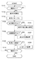
本マルチ画像表示システムでは、図2に示すように、まずステップS101において電源投入の有無を監視し、電源がオンされると、ステップS102で表示の初期化処理を行う。
【0042】
この表示の初期化処理では、図3に示すように、まずステップS201において、接続されている画像ソースを確認するための接続入力検知を行う。この検知は、各画像ソース1a,1b,1cから対応する動画入力部8a,8b,8cに入力される接続識別信号を監視することによって行われ、この接続識別信号は、一定期間毎に信号線S1−a〜cを介してマルチ画面制御部10に取り込まれるように構成されている。この接続識別信号は、“1”または“0”の2値信号からなり、画像ソースと動画入力部間を接続するケーブルが抜かれたり、画像ソースの電源が遮断された場合には、動画入力部が終端抵抗の役割を果たしているから、接続識別信号は“0”となり、画像ソースからの入力がないことを検知することができる。ここでは、この接続識別信号が“1”であり、各画像ソース1a,1b,1cが接続されているものとして以降の説明を行う。なお、各接続識別信号が“0”であるときには、この信号が“1”になるまで上記ステップS201において各接続識別信号の監視を行う。
【0043】
この接続識別信号により画像ソースの接続が検知されると、ステップS202で、接続が検知された画像ソースからの動画入力のためのパラメータ(表示ドット数、表示ライン数の情報、水平垂直タイミングなど)の設定を行う。ここでは、接続が検知された画像ソース1a,1b,1cからの動画入力のためのパラメータを検知し、その検知したパラメータを信号線S1−a〜cを介して対応する動画入力部8a,8b,8cに送出して設定する。これらパラメータは、各動画入力部が1ラインの同期を取る水平同期信号、1フレームまたは1フィールドの同期を取る垂直同期信号、1画素をサンプリングするためのクロック信号などを用いてクロック数、水平同期信号数を直接カウントすることによっても知ることが可能である。この接続された画像ソースからの入力タイミング情報は、同様に、信号線S1−a〜cを介してマルチ画面制御部10に取り込まれる。
【0044】
次いで、ステップS203に進み、接続が検知された少くなくとも1以上の画像ソースからの入力の画面上での表示レイアウトを決定する。初期化時には、予め決められているデフォルトのレイアウトで表示されることになる。続くステップS204では、決定されたレイアウト上での画像間の重なりの有無を判定し、この重なりがあるときには、各画像ソースの表示デバイス16上の表示開始位置と表示終了位置、水平垂直の拡大・縮小倍率をRAM24に書き込んだ後に、ステップS205に進む。これに対し、重なりがないときには、各画像ソースの表示デバイス16上の表示開始位置と表示終了位置、水平垂直の拡大・縮小倍率をRAM24に書き込んだ後に、ステップS205をスキップしてステップS206に進む。
【0045】
ステップS205では、重なりのレイヤ優先度(最上位の表示ほど優先度が高い)を決定してRAM24に書き込む。
【0046】
ステップS206では、解像度変換パラメータを決定し、決定したパラメータを信号線S2−a〜cを介して対応する解像度変換部9a,9b,9cに送出して設定する。続くステップS207では、解像度変換部9a,9b,9cの出力をメモリ部14に書き込む際に必要な書き込み用メモリアドレスの設定を行う。本実施の形態では、図4に示すように、メモリ部14を動画用3画面とOSD用1画面の計4画面の構成としている。よって、メモリ部14への格納時点では、オンスクリーン状態の形式ではない。ここでは、マルチ画面制御部10により図4に示す開始アドレス0〜3が信号線S2−a〜cを介して各解像度変換部9a,9b,9cおよびグラフィックアクセラレータ21に渡され、各書き込みアドレス生成部のメモリアドレスのオフセット値として用いられる。
【0047】
次いで、ステップS208に進み、マルチウィンドウ表示時の背景色(パターン)を設定する。具体的には、この背景色を出力合成部18の背景レジスタ37(図6を参照)にセットする。続くステップS209では、マルチ画面制御用OSDの表示設定を行う。具体的には、マルチ画面制御部10がOSDを描画するための命令をグラフィクアックセラレータ21に発行したり、グラフィクアックセラレータ21のDMA機能を用いてビットマップ形式に展開した文字やその他のデータをメモリ部14に書き込むことにより画面作成を行う。また、マルチ画面上でのOSDのレイアウトも決められる。この場合、優先度は最上位である。
【0048】
続くステップS210では、読み出し用メモリアドレスの設定を行う。これは、出力合成部18を動作させるための各種設定を行うことである。
【0049】
ここで、出力合成部18の概略動作について図6を用いて簡単に説明すると、出力合成部18は、合成制御部30を有し、この合成制御部30は、表示デバイス16の同期信号(Hsync,Vsync)を基準に動作する表示の水平画素数カウンタ、垂直ライン数カウンタ、カウンタと以下に述べるパラメータとの比較条件による各種制御信号を生成する。この合成制御部30は、マルチ画面制御部10からのS3信号により水平カウンタスタート値(Hsyncから有効画素が始まる期間)と垂直ラインスタート値(Vsync から有効ラインが始まる期間)、および水平画素数、垂直ライン数を取り込むことによって、表示期間のラスタスキャン走査をカウントする。また、同様に合成する入力(メモリ部14に書き込まれた画像ソースの入力)の読み出しアドレスに関しては、マルチ画面制御部10からのS3信号により各画像ソースのレイアウト情報を反映した合成スタートアドレス(合成制御部30の有効カウント開始からのオフセット値)、および水平画素数、垂直ライン数(これらはアドレス生成部31〜34にセットされる)を画面数分取り込み、合成制御部30のカウント値と一致したときには、信号線S5−a〜dを介してアドレス生成部31〜34の計数動作をキックする。これにより、4種類のアドレス生成部31〜34が独立にカウント動作をすることになる。以上のカウンタリセットは、通常の場合Vsync 毎に行われる。
【0050】
各アドレス生成部31〜34のカウンタ出力は、そのまま読み出しアドレスとなり、信号線S6−a〜dを介してアドレス選択部35に出力される。本実施の形態では、画面構成において独立して異なる画像ソースを管理しているから、これらから入力される画像の合成は、アドレス切替えにより行われる。すなわち、アドレス選択部35の切替え制御によって合成が実現されている。この切替えは、合成制御部30がマルチ画面制御部10からのS3信号により、レイアウト情報と優先度情報に基づいた合成切替えカウント数を取り込み、合成制御部30のカウンタの計数動作との比較を行い、一致したときには、アドレス切替え信号S7を発行することによりなされる。これによりメモリ部14からデータが読み出され、合成制御部30からのライト制御信号S9により制御されて読み出されたデータがデータバッファ36に書き込まれる。データバッファ36からのデータの読み出しは合成制御部30からのリード制御信号S9により制御され、読み出されたデータはデータ選択部40に入力される。合成制御部30は、合成すべきデータがないと判断したときには、データ切替え信号S8をデータ選択部40に出力し、データ選択部40は背景レジスタ37の背景データを出力する。
【0051】
次いで、ステップS211に進み、マルチ画面制御用カーソルの表示設定を行う。ここで、カーソルの描画方法について説明すると、まずマルチ画面制御部10は、カーソルを表示する矩形領域を判断し、その領域を特定の色(キーカラー)で塗りつぶす描画命令をグラフィックアクセラレータ21に発行する。グラフィックアクセラレータ21はこの描画命令を受けて図6に示すカーソル用メモリ38に矩形領域を書き込む。一方、マルチ画面制御部10は、予めROM17に準備しているカーソルパターンを前記矩形の塗りつぶし領域と重ね合わせる処理命令をグラフィックアクセラレータ21に発行する。グラフィックアクセラレータ21は、この処理命令を受けて演算処理を行い、カーソル用メモリ38の矩形領域をクロマキー付きカーソルパターンに書き換える。このカーソル用メモリ38への書き込みはライト制御信号S10により制御される。また、マルチ画面制御部10は、上述したと同様に、図6に示すキーカラーレジスタ39にキーカラーを設定する同時に、リモコン23からのカーソル制御情報に連動してカーソルを表示する位置を特定するとともに、この特定した表示位置に基づき算出されたカーソルの重ね合わせ位置情報を合成制御部30に渡す。合成制御部30は、カーソル合成を行う場合には、カーソル合成イネーブル信号S12をカーソル合成部41に出力する。この状態で、合成制御部30は、カーソルの重ね合わせ位置情報に基づいた合成切替えカウント数を取り込み、合成制御部30のカウンタのカウント値との比較を行い、一致したときには、リード制御信号S10を出力する。このカーソルデータは、カーソル合成部41でキーカラー部分をマスクすることによってデータ選択部40からのマルチ画面の合成データと重ね合わされ、すべての合成データが得られる。このようにして初期化が行われる。
【0052】
この初期化が終了すると、図2に示すステップS103に進み、表示をイネーブルにする。このときに表示デバイス16に表示されるマルチ画面は、図5に示すような画面例になる。
【0053】
次いで、ステップS104に進み、拡大縮小アクションの入力の有無を監視し、拡大縮小アクションの入力がなければ、ステップS106に進み、位置変更アクションの入力の有無を監視し、位置変更アクションの入力がなければ、ステップS108に進み、制御カーソル移動アクションの入力の有無を監視し、制御カーソル移動アクションの入力がなければ、ステップS110に進み、電源オフアクションの入力の有無を監視する。そして、電源オフアクションの入力がなければ、上記ステップS104からの処理を繰り返し実行する。
【0054】
上記ステップS104において拡大縮小アクションの入力有が検知されると、ステップS105に進み、入力された拡大縮小アクションに応じた表示の拡大縮小変更処理を実行する。この処理のルーチンは、上述したステップS203からS206までのルーチン(図3中の上記▲1▼の区間)に同じである。上記ステップS106において位置変更アクションの入力有が検知されると、ステップS107に進み、入力された位置変更アクションに応じた表示の位置変更処理を実行する。この処理のルーチンは、上述したステップS203からS205までのルーチン(図3中の上記▲2▼の区間)に同じである。上記ステップS108において制御カーソル移動アクションの入力有が検知されると、ステップS109に進み、入力された制御カーソル移動アクションに応じたカーソルパラメータ変更処理を実行する。この処理は、上述したステップS211に同じである。そして、上記ステップS110で電源オフアクションの入力が検知されると、本処理を終了する。
【0055】
このように、本マルチ画像表示システムは、入力された複数の画像の拡大、縮小、位置変更が可能なビュワーとして機能する。また、本マルチ画像表示システムには、マルチ画面上からインタラクティブな機能を有する各入力画面を操作するための制御カーソル役割可変機能が設けられている。
【0056】
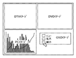
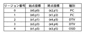
次に、この制御カーソル役割可変機能について図7および図8を参照しながら説明する。図7は図1のマルチ画像表示システムにおける制御カーソル役割可変機能を説明するための画面例を示す図、図8は図1のマルチ画像表示システムにおける制御カーソル役割可変機能に用いられるレイアウト管理テーブルを示す図である。
【0057】
この機能を実現するためには、まず接続されている画像ソースの種別を判別する必要がある。この画像ソース種別の判別は、上述したステップS201で接続入力検知とともに行われる。この画像ソース種別の判別方法としては、例えば、各画像ソースの種別に対応付け可能なデイップスイッチを設け、このデイップスイッチをユーザがマニュアル操作した結果に基づき画像ソースの種別を判定する方法がある。また、自動的に判別を行う方法では、画像ソースの1つとしてPC1bが接続されているとき、VESAが提案するP&DコネクタのIEEE1394ポートで本システムとPC間のやり取りを行うことにより画像ソースの種別を判別する。受信部1aに関しては、放送事業者がトランスポートストリーム中の識別子を定義することにより、この受信部1aに関する種別を判別する。
【0058】
次いで、マルチ画面制御部10は、上記ステップS203のレイアウト決定時に、マルチ画面の領域管理を行う。具体的には、図7に示したようなレイアウトを決定した場合、各入力画像の表示領域をリージョンと呼ぶ矩形領域に分割し、始点座標と終点座標、および検知した種別(OSDは本システム内で作成されるから、種別検知の必要はない)をリージョン毎に管理した図8に示すレイアウト管理テーブルを作成する。このレイアウト管理テーブルは、レイアウトが変更される度または接続された画像ソースが変わる度に更新される。
【0059】
上記ステップS211で作成されたマルチ画面制御用カーソルは、上記ステップS108で制御カーソルの異動がある毎にその表示位置座標が判断されるから、この表示位置座標と上記レイアウト管理テーブルとを参照してマルチ画面制御用カーソルがどのリージョン内にあるかを判別することができる。マルチ画面制御用カーソルがいずれのリージョンにも属さないときまたはリージョンの境界線上にあるときには、このカーソルは背景領域にあると判断される。このように、マルチ画面制御用カーソルは、画面上を自由に移動し、画面の位置変更や拡大縮小ウィンドウの選択などの表示レイアウト変更やOSDのメニュー選択などを実行するために使用される。
【0060】
ここで、図2に示すステップS109でのカーソルパラメータ変更にる統合操作モード時のマルチ画面制御用カーソルの描画処理について図9を参照しながら説明する。図9は図1のマルチ画像表示システムにおける統合操作モード時のマルチ画面制御用カーソルの描画処理を示すフローチャートである。
【0061】
まず、ステップS301において統合操作モードであるか否かを判定する。この統合操作モードとは、リモコン23に設けられた統合操作モードボタンを押したときに実行されるモードであり、インタラクティブな機能を有する各入力画面を操作するために、マルチ画面制御用カーソルが位置する領域(画像の画像ソースの種別)に応じてその役割を可変するモードである。
【0062】
統合操作モードが指示されていないときには、ステップS302に進み、通常のマルチ画面制御用カーソルの描画を行う。
【0063】
これに対し、統合操作モードが指示されているときには、ステップS303に進み、マルチ画面制御用カーソルがOSDリージョン(図7の例ではリージョン#4)内にあるか否かを判定する。マルチ画面制御用カーソルがOSDリージョン内にあるときには、上記ステップS302に進み、通常のマルチ画面制御用カーソルの描画を行う。マルチ画面制御用カーソルがOSDリージョン内にないときには、ステップS304に進む。
【0064】
ステップS304では、マルチ画面制御用カーソルがPCリージョン(図7の例ではリージョン#0,1)内にあるか否かを判定する。マルチ画面制御用カーソルがPCリージョン(図7の例ではリージョン#0,1)内にあるときには、ステップS306に進み、PCにはこの画面上でカーソルを発生させ、その操作を行うカーソル発生制御機能が設けられているから、PCにカーソル発生制御機能を移管する処理を行う。そして、本処理を終了する。このカーソル機能の移管処理については後述する。
【0065】
上記ステップS304において、マルチ画面制御用カーソルがPCリージョン内にないと判定されたときには、ステップS305に進み、マルチ画面制御用カーソルがDTVリージョン(図7の例ではリージョン#2,3)内にあるか否かを判定する。マルチ画面制御用カーソルがDTVリージョン内にないときには、上記ステップS302に進む。マルチ画面制御用カーソルがDTVリージョン内にあるときには、ステップS307に進み、ISDB専用カーソルの描画を行う。そして、本処理を終了する。このISDB専用カーソルの描画処理については後述する。
【0066】
この統合操作モードを抜けるときには、リモコン23の統合操作モードボタンを再び押すことによって統合操作モードが解除され、上記ステップS302により通常のマルチ画面制御用カーソルの制御モードへ移行することができる。
【0067】
次に、上記ステップS306のカーソル機能の移管処理について図15を参照しながら説明する。図15は図9のステップS306のカーソル機能の移管処理の手順を示すフローチャートである。
【0068】
本処理では、図15に示すように、まずステップS601で、PCリージョンにおいてユーザがPCにカーソル機能を移管することを要求しているか否かを監視する。ここで、ユーザがリモコン23の移管キーを押すと、リモコン制御部19は、この移管キーの押下に対応して発生されたコマンドを認識し、マルチ画面制御部10にカーソル移管要求を発行する。この移管要求が発行されると、マルチ画面制御部10は、ユーザがPCにカーソル機能を移管することを要求していると判断して、ステップS602に進み、カーソル合成イネーブル信号S12によりマルチ画面制御用カーソルの合成をディセーブルにすることによって、マルチ画面制御カーソルの描画をオフする。
【0069】
次いで、ステップS603に進み、信号S20によりリモコン制御部19へ移管モードに移行したことを通知する。これにより、リモコン制御部19は、移管モードでのコマンド(PCを制御するキーボードコマンド、マウス座標コマンド、移管解除コマンド)のみを受け付ける状態になる。そして、ステップS604に進み、PCとのシリアル接続の再構築を行う。具体的には、信号S4を介してシリアルバスI/F62を制御し、シリアルバスを一度非接続にした後に、再接続を行うとともに、再構築に要する時間を計測するための内部タイマを起動する。この動作によりUSB(またはIEEE1394)のシリアルプロトコルでは、PCがシリアルバス上のホスト、本システムがデバイスとしての関係が成立し、これによりシリアル接続のホットプラグ機能による再構築が完結する。
【0070】
次いで、ステップS605に進み、上記内部タイマのカウント値が予め設定された再構築時間のカウント値より大きくなるのを待ち、上記内部タイマのカウント値が予め設定された再構築時間のカウント値より大きくなると、本システムのカーソル機能の移管が完了したと判断され、この状態においては、ホストとなったPCは、リモコン23からのカーソル制御や入力操作を受け付け、本システムの表示画面上には、PCのカーソル発生制御機能により描画されたカーソル図形が画像データの一部として表示される。なお、実際には、リモコン23に代えて、本システム上にワイヤレスキーボードおよびワイヤレスマウスを設け、このワイヤレスキーボードおよびワイヤレスマウス側に制御方向を切り替えて使用することが好ましい。これにより、操作性に優れた操作環境をユーザに提供することができる。
【0071】
そして、ステップS606では、カーソル機能移管解除要求の発行のみを監視し、続くステップS607で、カーソル機能移管解除要求を検知したか否かを判定する。カーソル機能移管解除要求を検知しなければ、上記ステップS606に戻り、カーソル機能移管解除要求の発行を継続する。ここで、ユーザがリモコン23に設けられた移管解除ボタンを押すと、リモコン制御部19は、移管解除ボタンの押下に対応したコマンドを認識し、マルチ画面制御部10にカーソル移管解除要求を発行する。このカーソル機能移管解除要求を検知すると、ステップS608に進み、信号S4によりシリアルバスI/F62を制御してPCとのシリアル接続を切断する。
【0072】
次いで、ステップS609に進み、信号S20により統合モードに戻ったことをリモコン制御部19に通知する。これにより、リモコン制御部19は、統合モードでのコマンドの全てを受け付ける状態になる。そして、ステップS610に進み、カーソル合成イネーブル信号S12によりマルチ画面制御用カーソルの合成表示をイネーブルにする。これにより、マルチ画面制御用カーソルの描画がオンされ、移管モードからの復帰が行われる。
【0073】
このように、マルチ画面制御用カーソルがPC1bの表示領域に入ると、これを自動的に検知してマルチ画面制御用カーソルの発生、操作に関する制御をPC1b側の制御に移行するから、PCなどのようにカーソル発生制御機能を有する画像ソースの画像を表示したマルチ画面上でのリモート統合操作を実現することができる。
【0074】
次に、ISDB対応のデジタル放送の場合の統合操作について図10ないし図14を参照しながら説明する。図10はISDB対応のデジタル放送の画面イメージを示す図、図11は図9のステップS307のISDB専用カーソルの描画処理の手順を示すフローチャート、図12はISDB画像のレイアウト変換イメージを示す図、図13はISDB専用カーソルの描画処理に用いられるカーソルサイズ変更テーブルを示す図、図14はISDB専用カーソルの描画処理に用いられるカーソル移動量変更テーブルを示す図である。
【0075】
まず、ISDB対応のデジタル放送の画面描画方法について説明する。
【0076】
ISDB対応のデジタル放送の画面は、図10に示すように作成される。この画面例に示すように、放送局側は意図した画面表示を行うために、背景、動画、データ、メニューボタンなどをオブジェクトいう形式でMHEG−5などのマルチメディア記述言語で記述して送信する。各オブジェクトは、位置、大きさ、ボタン、ビットマップ、テキストなどの属性を有する。本表示システムでは、この属性情報からMPEG2の動画以外のオブジェクトを前述したOSDの生成と同様の方法で生成する。MPEG2の動画は、図1に示す画像復号部6から解像度変換部9aに至る系を用いて再生し、前述した方法を用いて出力合成部18で合成すれば、図10に示すような放送局側が意図した画面を再現することができる。ここで、再生時には、MPEG2の解像度はその画像を指定された大きさに収めることが可能な解像度に変換される。この一連の処理は、放送局側が意図した表示解像度で表現する場合の例である。
【0077】
ここで、本マルチ画像表示システムでISDB画面をマルチ画面上の1画面として扱う場合には、レイアウト変換処理が必要であり、このレイアウト変換処理について図12を参照しながら説明する。
【0078】
本マルチ画像表示システムでISDB画面を扱う場合には、図12に示すように、ISDB画面50がマルチ画面上の1画面として表示される。この画面50は、放送局側が意図した表示解像度で表示した場合のものである。放送局側が意図した表示解像度を、水平画素方向X画素、垂直ライン方向Yラインとすると、画面50は、(X,0)、(0,Y)の座標で表される。ここで、マルチ画面表示のために、ユーザがレイアウト変更をする場合、レイアウトを指定された大きさにまたその位置を変換しなければならない。水平方向M(1>M>0)倍、垂直方向N(1>N>0)倍にそれぞれ解像度を変換する場合は、この解像度変換により画面50が画面51になり、その座標は(X´,0)、(0,Y´)になる。このときの変換は、次の(1)および(2)式で表される。
【0079】
X´=MX …(1)
Y´=NY …(2)
原点(0,0)から移動オフセット(Xm,Ym)に位置変更する場合には、画面51が画面52の位置に移動し、その座標は、(X”,0)、(0,Y”)に変化する。このときの変換は、次の(3)および(4)式で表される。
【0080】
X”=X´+Xm …(3)
Y”=Y´+Ym …(4)
上記(1)〜(4)式により、解像度変換と位置変更を組み合わせたレイアウト座標変換は、
X”=MX+Xm …(5)
Y”=NY+Ym …(6)
となる。この(5)および(6)式に従いレイアウトされたISDB画面の位置情報はマルチ画面表示に適宜変換され、描画が行われる。
【0081】
次に、統合操作モード時における上記ステップS307の詳細な処理手順について図11を参照しながら説明する。
【0082】
マルチ画面制御用カーソルがDTVリージョン(図7の例ではリージョン#2,3)内に入ると、上述したように、上記ステップS307で、ISDB専用カーソルの描画を行う。このISDB専用カーソルの描画では、図11に示すように、まずステップS501においてISDB専用カーソルの表示が必要であるか否かを判定する。本実施の形態では、図10に示すように、矢印カーソルをマルチ画面制御用カーソルとして用いている。ここで、ISDB専用のカーソルの表示(例えば、ボタン領域の輪郭を特定色で枠付けしたり、ボタン領域全体の色反転)を放送局側から指定されている場合、または意図的にカーソルの種類を変えたいときには、ISDB専用カーソルの表示が必要であると判断してステップS502に進み、現在表示されているマルチ画面制御用カーソルを非表示にする。具体的には、図6に示すカーソル合成イネーブル信号S12によりマルチ画面制御用カーソルの合成をディセーブルにする。
【0083】
次いで、ステップS503に進み、ISDB専用カーソルの表示を行う。例えば、枠カーソルを使う場合には、シナリオ記述言語からボタンの位置、数を認識し(複数あるときにはすべて認識する)、デフォルトのボタンに枠カーソルを表示する。この表示は、上述したOSD描画と同じ方法でボタンの枠部分の矩形を特定色に塗りつぶし、その上にボタンを描画することにより行うことができる。枠カーソルの移動は、上記認識したボタンに対して予め決められた順番に従いリモコン23のボタンに連動して枠カーソル描画のON/OFFを行うようにすればよい。
【0084】
上記ステップS501でISDB専用カーソルの表示が必要でないと判定されたときには、ステップS504に進み、カーソルサイズを設定する。これは、ISDBのボタンの大きさを判断し、本システム全体を制御するマルチ画面制御用カーソルの大きさを、ユーザが所望のボタンを確実に選択することができる大きさに設定するためである。なお、カーソルの大きさを変更する必要がない場合、このカーソルの大きさは現在の大きさに保持される。
【0085】
続くステップS505では、カーソル色を設定する。これは、ISDBの操作モードにあることをユーザに認識し易くすることを目的としており、通常のマルチ画面制御用カーソルの色と異なる色を設定する。なお、色変更が必要でない場合には、現在の色が用いられる。
【0086】
次いで、ステップS506に進み、カーソル移動量の設定を行う。ISDBの画面上でカーソルを移動させる際に通常のマルチ画面制御時における画面移動量と変えた方が使い勝手が向上する場合には、このカーソル移動量を変更する。なお、カーソル移動量の変更が必要でないときには、この移動量は現在の値に保持される。続くステップS507では、操作ボタンの位置を記録する。これは、ISDB画面上のボタン領域にカーソルが位置するときに、リモコン23によりこのボタンを選択するアクションを起こしたときに、シーンを切り替えるタイミングをマルチ画面制御部10が認識するためである。
【0087】
以上の設定(ステップS504〜S507)は、ISDBのカーソル表示のベース設定として、後述する設定変更時にも参照される。
【0088】
次いで、ステップS508に進み、放送局側のレイアウトに従ってISDB等倍表示を行うか否かを判定する。ここで、等倍表示を行うときには、ステップS509に進み、マルチ画面上の上記設定に応じた変更表示を行う。等倍表示を行わないときには、ユーザが意図的にマルチ画面表示のためにレイアウトを変更すると判断してステップS510に進み、解像度を変換するか否かを判定する。解像度を変換するときには、ステップS511に進み、解像度変換後のISDB画面に適合したカーソルサイズへの変更を行う。このカーソルサイズの変更は、カーソルサイズ変更テーブルを参照して行われる。このカーソルサイズ変更テーブルは、図13に示すように、カーソルサイズと変倍率との関係を表すテーブルであり、本例では、上記ステップS504で設定したカーソルサイズを変倍率1に対する基準値として、カーソルサイズと変倍率との関係を表している。このテーブルから分かるように、変倍率が大きくなるほどカーソルサイズが段階的に大きくなるように設定される。
【0089】
続くステップS512では、解像度変換後のISDB画面に適合したカーソル移動量への変更を行う。このカーソル移動量の変更は、カーソル移動量変更テーブルを参照して行われる。このカーソル移動量変更テーブルは、図14に示すように、カーソル移動量と変倍率との関係を表すテーブルであり、本例では、上記ステップS506で設定したカーソル移動量を変倍率1に対する基準値として、カーソルサイズと変倍率との関係を表している。このテーブルから分かるように、変倍率が大きくなるほどカーソル移動量が段階的に大きくなるように設定される。
【0090】
次いで、ステップS513に進み、レイアウト変更に伴う選択ボタン位置の記憶変更を行う。これは、上記(5),(6)式においてオフセット座標(Xm,Ym)=(0,0)と置き換えることにより行われる。そして、ステップS514に進む。
【0091】
これに対し、上記ステップS510で解像度の変換を行わないと判定されると、上記ステップS511〜S513をスキップしてステップS514に進む。ステップS504では、選択ボタンの位置変更を行うか否かを判定する。選択ボタンの位置変更を行う場合には、ステップS515に進み、レイアウト変更に伴う選択ボタン位置の記憶変更を再び行う。これは、上記(5),(6)式において変倍率をM=N=0と置き換えることにより行われる。そして、上記ステップS509に進む。上記ステップS514で、選択ボタンの位置変更を行わないと判定されたときには、上記ステップS515をスキップして上記ステップS509に進む。
【0092】
ユーザがマルチ画面上でレイアウト変更されたISDB画面のボタンを選択してインタラクティブなアクションを起こすときには、マルチ画面制御部10が、変更されたカーソルの位置(X”,Y”)を、上記(3)式から得られた次の(7),(8)式
X=(X”−Xm)/M …(7)
Y=(Y”−Ym)/N …(8)
に従って放送局側が意図する位置(X,Y)に戻し、この戻した位置と受信時のボタン属性を有する領域との比較、監視を行うことによって、両者が一致すれば、ボタン選択アクションと見なす。これにより、対応するボタンの選択が行われることになる。その結果、マルチ画面上での正確なシーンの切替えを行うことができる。
【0093】
このように、マルチ画面制御用カーソルがDTVの表示領域に入ると、これを自動的に検知してカーソルの種類を切り替え、またはカーソルのサイズ、色、移動量を切り替えることにより、操作の種別にあった最適な操作環境が得られる。また、マルチ画面レイアウトの変更の際も、インタラクティブなボタンの選択を正確に認識することができ、シーンの切替えを正確に行うことができる。その結果、ISDB対応のDTV入力のマルチ画面上での統合操作を実現することができる。
【0094】
【発明の効果】
以上説明したように、本発明によれば、マルチ画面で表示される各画像に対する操作を一元的に行うことができる。
また、マルチ画面制御カーソルの表示位置に対応する画像の画像ソースがカーソル生成機能を有する画像ソースであるときに、マルチ画面制御カーソルを画像ソースのカーソルに切り替えることにより、カーソル生成機能を有する画像ソース側での画像の編集、切替えを、画像ソース側で行うことなく、マルチ画面において行うことができる。
また、マルチ画面制御カーソルの表示位置に対応する画像の画像ソースが、カーソル生成機能を有する画像ソースである場合、シリアルバスを介して、カーソル生成機能を有する画像ソースに、カーソルの生成を要求することにより、カーソルの生成を画像ソースに簡単に移管することができる。
【0095】
また、本発明によれば、マルチ画面制御カーソルの表示位置に対応する画像ソースが、カーソルの属性情報が所定の記述言語で記述された画像ソースである場合に、マルチ画面制御カーソルを非表示にして、所定の記述言語で記述されたカーソルの属性情報に基づいて、所定の記述言語専用カーソルを表示する制御を行うことにより、画面に適した快適なカーソル操作を行うことができる。
【図面の簡単な説明】
【図1】本発明のマルチ画像表示システムの実施の一形態の構成を示すブロック図である。
【図2】図1のマルチ画像表示システムにおけるマルチ画像表示動作の手順を示すフローチャートである。
【図3】図2のステップS102の表示の初期化処理の手順を示すフローチャートである。
【図4】図1のマルチ画像表示システムのメモリ部14における画像データのメモリアドレスマップを示す図である。
【図5】図1のマルチ画像表示システムの初期化時の画面表示例を示す図である。
【図6】図1のマルチ画像表示システムの出力合成部の構成を示すブロック図である。
【図7】図1のマルチ画像表示システムにおける制御カーソル役割可変機能を説明するための画面例を示す図である。
【図8】図1のマルチ画像表示システムにおける制御カーソル役割可変機能に用いられるレイアウト管理テーブルを示す図である。
【図9】図1のマルチ画像表示システムにおける統合操作モード時のマルチ画面制御用カーソルの描画処理を示すフローチャートである。
【図10】ISDB対応のデジタル放送の画面イメージを示す図である。
【図11】図9のステップS307のISDB専用カーソルの描画処理の手順を示すフローチャートである。
【図12】ISDB画像のレイアウト変換イメージを示す図である。
【図13】ISDB専用カーソルの描画処理に用いられるカーソルサイズ変更テーブルを示す図である。
【図14】ISDB専用カーソルの描画処理に用いられるカーソル移動量変更テーブルを示す図である。
【図15】図9のステップS306のカーソル機能の移管処理の手順を示すフローチャートである。
【符号の説明】
1a ISDB対応受信部(画像ソース)
1b PC(画像ソース)
1c DVD(画像ソース)
5 オーディオ復号部
6 画像復号部
7 データ復号部
8a,8b,8c 動画入力部
9a,9b,9c 解像度変換部
10 マルチ画面制御部
14 メモリ部
16 表示デバイス
18 出力合成部
19 リモコン制御部
21 グラフィックアクセラレタータ
23 リモコン
62 シリアルバスI/F[0001]
BACKGROUND OF THE INVENTION
The present invention relates to a multi-image display system and a multi-image display method capable of simultaneously displaying image data respectively input from a plurality of image sources on one display device.
[0002]
[Prior art]
In recent years, image data supplied from a DTV (digital television), DVD (digital video disk, etc.), PC (personal computer), etc. has been increasingly displayed on a large display device such as a liquid crystal projector or a plasma display. In response to this, in the future, in the home, this large display device is positioned as a central device of multimedia, and applications in a form in which each video medium is integrated and displayed on the display device are desired. From such a background, the image display system needs a function capable of simultaneously displaying a plurality of images. The currently proposed large display device has a function of arbitrarily laying out and displaying each image data supplied from a plurality of different connected media on the screen of the display device. Display image data simultaneously. That is, a multi-image display system is constructed by using a large display device as a multi-screen viewer.
[0003]
[Problems to be solved by the invention]
However, in the above-described conventional multi-image display system, when the image data displayed on the screen is PC image data, operations related to editing and switching of the image data to be displayed are changed to operations using a cursor or mouse on the PC side. Must be migrated. This is because cursor generation means and application control are provided in the PC. When a broadcast image such as an interactive integrated digital broadcasting system is laid out as a part of multi-screen display, a switching action to switch this broadcast screen after returning to the resolution intended by the broadcaster once Have to do. This is because the menu screen is configured with the resolution intended by the broadcaster for the currently scheduled broadcast image, and when the user performs resolution conversion for multi-display, interactive selection is performed. This is because there is a possibility that operational troubles such as inability to occur. As a result, in the conventional multi-image display system, each medium cannot be controlled centrally with the large display device as the center of control. That is, the user interface is a user interface with poor operability.
[0004]
An object of the present invention is to provide a multi-image display system and a multi-image display method capable of performing operations on each image on a multi-screen in a unified manner.
[0005]
[Means for Solving the Problems]
In order to achieve the above object, the present invention provides a multi-screen on a display device for a plurality of images input from a plurality of connected image sources.soShowRuIn the multi-image display system, image source discrimination means for discriminating the type of each connected image source;,in frontMulti-drawIn terms ofMulti-screen control cursor for input operationsTheGenerationDisplay on the multi-screen, and the multi-screen control cursorCursor control means for controlling the operation of the multi-imageOn the faceDisplay position identifying means for identifying the display position of the multi-screen control cursor inWhen the image source determining unit determines that the image source corresponding to the display position of the multi-screen control cursor is an image source having a cursor generation function, the cursor control unit selects the multi-screen control cursor. Control to hide and generate the cursor to the image source having the cursor generation functionIt is characterized by that.
[0006]
In order to achieve the above object, the present invention provides a multi-image display for displaying a plurality of images input from a plurality of connected image sources on a display device in a multi-screen.systemThe image source determining means for determining the type of each connected image source, and generating a multi-screen control cursor for performing an input operation on the multi-screen and displaying the multi-screen control cursor on the multi-screen. Cursor control means for performing control related to the operation of the display, and display position identification means for identifying the display position of the multi-screen control cursor on the multi-screen, and the display position of the multi-screen control cursor is determined by the image source determination means. When it is determined that the corresponding image source is an image source in which the attribute information of the cursor is described in a predetermined description language, the cursor control meansHide the multi-screen control cursor,Based on the attribute information of the cursor described in the predetermined description language,Control to display the cursor for the predetermined description languageIt is characterized by that.
[0007]
The present invention also provides a multi-image display method in order to achieve the above object.
[0025]
DETAILED DESCRIPTION OF THE INVENTION
Embodiments of the present invention will be described below with reference to the drawings.
[0026]
FIG. 1 is a block diagram showing a configuration of an embodiment of a multi-image display system of the present invention.
[0027]
As shown in FIG. 1, the multi-image display system simultaneously displays images supplied from three independent image sources (ISDB-
[0028]
Here, the ISDB will be described before the description of the ISDB-compatible DTV receiving unit (hereinafter referred to as a receiving unit) 1a. With the development of digital technology, an interactive integrated digital broadcasting system (ISDB: Integrated Services Digital Broadcasting) that digitizes information including broadcast signals is being researched and developed in the broadcasting industry. Specifically, the ISDB system digitally converts current broadcast signals (standard television signals, high-definition signals), software and facsimile data, and multimedia information such as voice, graphics, and images. It is a broadcasting system that performs transmission processing after performing modulation processing in conformity with the transmission form after integrating and multiplexing them. When various types of information including broadcast signals are multiplexed, it is possible to simultaneously multiplex and transmit additional information used as control information on the receiving side in addition to these pieces of information. The integrated ISDB broadcast signal (digital signal) is transmitted using a terrestrial wave, a satellite wave, an optical cable, or the like. The receiving terminal side receives the integrated ISDB broadcast signal, discriminates the target signal, displays it on the monitor and enjoys it as a normal television broadcast, of course, using the recording means, It can be saved and transferred to other terminals. Furthermore, if the received additional information is used, the received information can be used according to the user's preference, such as monitor control, recording control, and processing control on the monitored image. That is, an interactive broadcasting system can be constructed.
[0029]
The
[0030]
The PC 1b is a computer such as a personal computer or a workstation, and image data output from the
[0031]
The DVD 1c is a DVD device that reproduces a DVD ROM or the like, and image data output from this device is input to the moving
[0032]
The moving
[0033]
The image data captured in each of the moving
[0034]
The image data output from each of the
[0035]
The read image data is input to the
[0036]
The
[0037]
The
[0038]
The
[0039]
The
[0040]
Next, a multi-image display operation in the multi-image display system will be described with reference to FIGS. 2 is a flowchart showing the procedure of the multi-image display operation in the multi-image display system of FIG. 1, FIG. 3 is a flowchart showing the procedure of the display initialization process in step S102 of FIG. 2, and FIG. 4 is the multi-image display of FIG. 5 is a diagram showing a memory address map of image data in the
[0041]
In this multi-image display system, as shown in FIG. 2, first, in step S101, the presence or absence of power-on is monitored. When the power is turned on, display initialization processing is performed in step S102.
[0042]
In this display initialization process, as shown in FIG. 3, first, in step S201, connection input detection for confirming the connected image source is performed. This detection is performed by monitoring connection identification signals input from the
[0043]
When the connection of the image source is detected by this connection identification signal, in step S202, parameters for moving image input from the image source whose connection is detected (information on the number of display dots, the number of display lines, horizontal and vertical timing, etc.) Set up. Here, parameters for moving image input from the
[0044]
Next, the process proceeds to step S203, and the display layout on the screen of the input from at least one or more image sources whose connection has been detected is determined. At the time of initialization, it is displayed in a predetermined default layout. In the subsequent step S204, it is determined whether or not there is an overlap between images on the determined layout. When there is an overlap, the display start position and display end position on the
[0045]
In step S205, the overlapping layer priority (the higher the display, the higher the priority) is determined and written to the
[0046]
In step S206, resolution conversion parameters are determined, and the determined parameters are sent and set to the corresponding
[0047]
In step S208, the background color (pattern) for multi-window display is set. Specifically, this background color is set in the background register 37 (see FIG. 6) of the
[0048]
In the subsequent step S210, a read memory address is set. This is to perform various settings for operating the
[0049]
Here, the general operation of the
[0050]
The counter output of each of the
[0051]
Next, the process proceeds to step S211, and the display setting of the multi-screen control cursor is performed. Here, a cursor drawing method will be described. First, the
[0052]
When this initialization is completed, the process proceeds to step S103 shown in FIG. 2 to enable display. The multi-screen displayed on the
[0053]
Next, the process proceeds to step S104, where the presence / absence of an enlargement / reduction action is monitored. If there is no enlargement / reduction action input, the process proceeds to step S106, where the presence / absence of a position change action is monitored. For example, the process proceeds to step S108 to monitor whether there is an input of the control cursor movement action. If there is no input of the control cursor movement action, the process proceeds to step S110, and the presence of input of the power-off action is monitored. If there is no power off action input, the processing from step S104 is repeated.
[0054]
If it is detected in step S104 that an enlargement / reduction action has been input, the process advances to step S105 to execute a display enlargement / reduction change process corresponding to the input enlargement / reduction action. This processing routine is the same as the above-described routine from step S203 to S206 (section (1) in FIG. 3). If it is detected in step S106 that the position change action is input, the process proceeds to step S107, and a display position change process corresponding to the input position change action is executed. This processing routine is the same as the above-described routine from step S203 to S205 (section (2) in FIG. 3). If it is detected in step S108 that a control cursor movement action has been input, the process proceeds to step S109 to execute a cursor parameter change process corresponding to the input control cursor movement action. This process is the same as step S211 described above. Then, when the input of the power off action is detected in step S110, this process is terminated.
[0055]
As described above, the multi-image display system functions as a viewer capable of enlarging, reducing, and changing the position of a plurality of input images. The multi-image display system is also provided with a control cursor role variable function for operating each input screen having an interactive function from the multi-screen.
[0056]
Next, the control cursor role variable function will be described with reference to FIGS. 7 is a view showing an example of a screen for explaining the control cursor role variable function in the multi-image display system of FIG. 1, and FIG. 8 shows a layout management table used for the control cursor role variable function in the multi-image display system of FIG. FIG.
[0057]
In order to realize this function, it is necessary to first determine the type of the connected image source. The determination of the image source type is performed together with the connection input detection in step S201 described above. As a method for determining the image source type, for example, there is a method in which a dip switch that can be associated with each image source type is provided and the type of the image source is determined based on a result of manual operation of the dip switch by the user. Further, in the method of automatically discriminating, when the
[0058]
Next, the
[0059]
The display position coordinate of the multi-screen control cursor created in step S211 is determined every time the control cursor is moved in step S108, so refer to this display position coordinate and the layout management table. It is possible to determine in which region the multi-screen control cursor is located. When the multi-screen control cursor does not belong to any region or is on the boundary line of the region, this cursor is determined to be in the background area. As described above, the multi-screen control cursor is used to move freely on the screen and execute display layout changes such as screen position change and enlargement / reduction window selection, OSD menu selection, and the like.
[0060]
Here, the drawing process of the multi-screen control cursor in the integrated operation mode in the cursor parameter change in step S109 shown in FIG. 2 will be described with reference to FIG. FIG. 9 is a flowchart showing a drawing process of the multi-screen control cursor in the integrated operation mode in the multi-image display system of FIG.
[0061]
First, in step S301, it is determined whether or not the integrated operation mode is set. This integrated operation mode is a mode that is executed when an integrated operation mode button provided on the
[0062]
When the integrated operation mode is not instructed, the process proceeds to step S302, and a normal multi-screen control cursor is drawn.
[0063]
On the other hand, when the integrated operation mode is instructed, the process proceeds to step S303 to determine whether or not the multi-screen control cursor is in the OSD region (
[0064]
In step S304, it is determined whether or not the multi-screen control cursor is in the PC region (
[0065]
If it is determined in step S304 that the multi-screen control cursor is not in the PC region, the process proceeds to step S305, where the multi-screen control cursor is in the DTV region (
[0066]
When exiting the integrated operation mode, the integrated operation mode is canceled by pressing the integrated operation mode button on the
[0067]
Next, the cursor function transfer processing in step S306 will be described with reference to FIG. FIG. 15 is a flowchart showing the procedure of the cursor function transfer process in step S306 of FIG.
[0068]
In this process, as shown in FIG. 15, first, in step S601, it is monitored whether or not the user requests the PC to transfer the cursor function in the PC region. Here, when the user presses the transfer key of the
[0069]
In step S603, the
[0070]
Next, the process proceeds to step S605, and waits for the count value of the internal timer to be greater than the preset value of the rebuild time, and the count value of the internal timer is greater than the preset value of the rebuild time. Then, it is determined that the transfer of the cursor function of the system has been completed. In this state, the host PC accepts the cursor control and input operation from the
[0071]
In step S606, only the issuance of the cursor function transfer cancellation request is monitored, and in subsequent step S607, it is determined whether or not the cursor function transfer cancellation request is detected. If no cursor function transfer cancellation request is detected, the process returns to step S606 to continue issuing the cursor function transfer cancellation request. Here, when the user presses the transfer release button provided on the
[0072]
Next, the process proceeds to step S609, and the
[0073]
As described above, when the multi-screen control cursor enters the display area of the
[0074]
Next, an integration operation in the case of ISDB-compatible digital broadcasting will be described with reference to FIGS. FIG. 10 is a diagram showing a screen image of ISDB-compatible digital broadcasting, FIG. 11 is a flowchart showing the procedure of ISDB dedicated cursor drawing processing in step S307 of FIG. 9, and FIG. 12 is a diagram showing a layout conversion image of an ISDB image. 13 is a diagram showing a cursor size change table used for ISDB dedicated cursor drawing processing, and FIG. 14 is a diagram showing a cursor movement amount changing table used for ISDB dedicated cursor drawing processing.
[0075]
First, a screen drawing method for ISDB-compatible digital broadcasting will be described.
[0076]
An ISDB-compatible digital broadcast screen is created as shown in FIG. As shown in this screen example, in order to perform the intended screen display, the broadcasting station side describes the background, moving image, data, menu button, etc. in the form of an object in a multimedia description language such as MHEG-5 and transmits it. . Each object has attributes such as position, size, button, bitmap, and text. In this display system, an object other than the MPEG2 moving image is generated from this attribute information in the same manner as the OSD generation described above. An MPEG2 moving image is reproduced using the system from the image decoding unit 6 to the resolution conversion unit 9a shown in FIG. 1, and is synthesized by the
[0077]
Here, when the ISDB screen is handled as one screen on the multi-screen in this multi-image display system, layout conversion processing is necessary, and this layout conversion processing will be described with reference to FIG.
[0078]
When the ISDB screen is handled by the multi-image display system, the
[0079]
X ′ = MX (1)
Y '= NY (2)
When the position is changed from the origin (0, 0) to the movement offset (Xm, Ym), the
[0080]
X ″ = X ′ +Xm ... (3)
Y "= Y '+Ym (4)
According to the above formulas (1) to (4), layout coordinate conversion combining resolution conversion and position change is
X ″ = MX + Xm (5)
Y ″ = NY + Ym (6)
It becomes. The position information of the ISDB screen laid out according to the equations (5) and (6) is appropriately converted into a multi-screen display, and drawing is performed.
[0081]
Next, a detailed processing procedure of step S307 in the integrated operation mode will be described with reference to FIG.
[0082]
When the multi-screen control cursor enters the DTV region (
[0083]
In step S503, the ISDB dedicated cursor is displayed. For example, when a frame cursor is used, the position and number of buttons are recognized from the scenario description language (when there are a plurality of buttons), the frame cursor is displayed on the default button. This display can be performed by painting the button frame with a specific color in the same way as the OSD drawing described above and drawing the button on the rectangle. The movement of the frame cursor may be performed by turning ON / OFF the frame cursor drawing in conjunction with the buttons on the
[0084]
If it is determined in step S501 that display of the ISDB dedicated cursor is not necessary, the process proceeds to step S504, where the cursor size is set. This is because the size of the ISDB button is determined, and the size of the multi-screen control cursor for controlling the entire system is set to a size that allows the user to reliably select the desired button. . When there is no need to change the cursor size, the cursor size is maintained at the current size.
[0085]
In the subsequent step S505, a cursor color is set. This is intended to make it easier for the user to recognize that the operation mode is ISDB, and sets a color different from the color of the normal multi-screen control cursor. If no color change is necessary, the current color is used.
[0086]
In step S506, the cursor movement amount is set. When the cursor is moved on the ISDB screen and the usability is improved by changing the screen movement amount in the normal multi-screen control, the cursor movement amount is changed. When there is no need to change the cursor movement amount, this movement amount is held at the current value. In the subsequent step S507, the position of the operation button is recorded. This is because, when the cursor is positioned in the button area on the ISDB screen, the
[0087]
The above settings (steps S504 to S507) are also referred to as a setting for the ISDB cursor display when the setting is changed later.
[0088]
Next, the process proceeds to step S508, and it is determined whether or not to perform ISDB equal magnification display according to the layout on the broadcasting station side. Here, when the same size display is performed, the process proceeds to step S509, and the change display according to the above setting on the multi-screen is performed. When the same size display is not performed, it is determined that the user intentionally changes the layout for the multi-screen display, the process proceeds to step S510, and it is determined whether or not the resolution is to be converted. When converting the resolution, the process proceeds to step S511, and the cursor size is adapted to the ISDB screen after the resolution conversion. The cursor size is changed by referring to the cursor size change table. As shown in FIG. 13, this cursor size change table is a table showing the relationship between the cursor size and the scaling factor. In this example, the cursor size set in step S504 is used as a reference value for the
[0089]
In the subsequent step S512, the cursor movement amount adapted to the ISDB screen after resolution conversion is changed. The change in the cursor movement amount is performed with reference to the cursor movement amount change table. As shown in FIG. 14, the cursor movement amount change table is a table representing the relationship between the cursor movement amount and the scaling factor. In this example, the cursor movement amount set in step S506 is the reference value for the
[0090]
Next, the process proceeds to step S513, and the storage of the selection button position associated with the layout change is changed. This is performed by replacing the offset coordinates (Xm, Ym) = (0, 0) in the above formulas (5) and (6). Then, the process proceeds to step S514.
[0091]
On the other hand, if it is determined in step S510 that resolution conversion is not performed, steps S511 to S513 are skipped and the process proceeds to step S514. In step S504, it is determined whether or not to change the position of the selection button. When the position of the selection button is changed, the process proceeds to step S515, and the memory change of the selection button position accompanying the layout change is performed again. This is done by replacing the scaling factor with M = N = 0 in the above equations (5) and (6). Then, the process proceeds to step S509. If it is determined in step S514 that the position of the selection button is not changed, the process skips step S515 and proceeds to step S509.
[0092]
When the user selects a button on the ISDB screen whose layout has been changed on the multi-screen and causes an interactive action, the
X = (X ″ −Xm) / M (7)
Y = (Y ″ −Ym) / N (8)
Thus, the position is returned to the position (X, Y) intended by the broadcasting station side, and the returned position is compared with the area having the button attribute at the time of reception. As a result, the corresponding button is selected. As a result, accurate scene switching on the multi-screen can be performed.
[0093]
As described above, when the multi-screen control cursor enters the display area of the DTV, this is automatically detected and the type of the cursor is switched, or the size, color, and movement amount of the cursor are switched to change the type of operation. The optimum operating environment can be obtained. Further, even when the multi-screen layout is changed, interactive button selection can be recognized accurately, and scene switching can be performed accurately. As a result, it is possible to realize an integration operation on a multi-screen of DTV input compatible with ISDB.
[0094]
【The invention's effect】
As described above, according to the present invention, a multi-screenDisplayed inOperations on each image can be performed centrally.
In addition, when the image source of the image corresponding to the display position of the multi-screen control cursor is an image source having a cursor generation function, the image source having the cursor generation function is switched by switching the multi-screen control cursor to the cursor of the image source. Image editing and switching on the side can be performed on a multi-screen without being performed on the image source side.
Further, when the image source of the image corresponding to the display position of the multi-screen control cursor is an image source having a cursor generation function, the image source having the cursor generation function is requested to generate a cursor via the serial bus. Thus, the generation of the cursor can be easily transferred to the image source.
[0095]
According to the present invention, when the image source corresponding to the display position of the multi-screen control cursor is an image source in which the attribute information of the cursor is described in a predetermined description language,Hide the multi-screen control cursor,Based on cursor attribute information written in a given description language,Performs control to display a cursor for a specific description languageThus, a comfortable cursor operation suitable for the screen can be performed.
[Brief description of the drawings]
FIG. 1 is a block diagram showing a configuration of an embodiment of a multi-image display system of the present invention.
FIG. 2 is a flowchart showing a procedure of a multi-image display operation in the multi-image display system of FIG.
FIG. 3 is a flowchart showing a procedure of display initialization processing in step S102 of FIG. 2;
4 is a diagram showing a memory address map of image data in the
5 is a diagram showing a screen display example at the time of initialization of the multi-image display system of FIG. 1. FIG.
6 is a block diagram illustrating a configuration of an output composition unit of the multi-image display system of FIG. 1. FIG.
7 is a diagram showing an example of a screen for explaining a control cursor role variable function in the multi-image display system of FIG. 1. FIG.
8 is a diagram showing a layout management table used for a control cursor role variable function in the multi-image display system of FIG. 1. FIG.
9 is a flowchart showing a drawing process of a multi-screen control cursor in the integrated operation mode in the multi-image display system of FIG.
FIG. 10 is a diagram showing a screen image of ISDB-compatible digital broadcasting.
11 is a flowchart showing a procedure of ISDB dedicated cursor drawing processing in step S307 of FIG. 9;
FIG. 12 is a diagram showing a layout conversion image of an ISDB image.
FIG. 13 is a diagram illustrating a cursor size change table used for ISDB dedicated cursor drawing processing;
FIG. 14 is a diagram showing a cursor movement amount change table used for ISDB dedicated cursor drawing processing;
FIG. 15 is a flowchart showing a procedure of a cursor function transfer process in step S306 of FIG. 9;
[Explanation of symbols]
1a ISDB compatible receiver (image source)
1b PC (image source)
1c DVD (image source)
5 Audio decoding part
6 Image decoding unit
7 Data decoder
8a, 8b, 8c Video input part
9a, 9b, 9c Resolution converter
10 Multi-screen controller
14 Memory part
16 display devices
18 Output synthesis unit
19 Remote control unit
21 Graphic Accelerator Letter
23 Remote control
62 Serial bus I / F
Claims (6)
接続された各画像ソースの種別を判別する画像ソース判別手段と、
前記マルチ画面での入力操作を行うためのマルチ画面制御カーソルを生成して前記マルチ画面に表示し、該マルチ画面制御カーソルの操作に関する制御を行うカーソル制御手段と、
前記マルチ画面における前記マルチ画面制御カーソルの表示位置を識別する表示位置識別手段とを備え、
前記画像ソース判別手段により、前記マルチ画面制御カーソルの表示位置に対応する画像ソースが、カーソル生成機能を有する画像ソースであると判別された場合に、前記カーソル制御手段は、前記マルチ画面制御カーソルを非表示にして、前記カーソル生成機能を有する画像ソースにカーソルを生成させる制御を行うことを特徴とするマルチ画像表示システム。In a multi-image display system for displaying a plurality of images input from a plurality of connected image sources on a multi-screen on a display device,
Image source discrimination means for discriminating the type of each connected image source;
A cursor control means for generating a multi-screen control cursor for performing an input operation on the multi-screen, displaying the multi-screen control cursor on the multi-screen, and controlling the operation of the multi-screen control cursor;
Display position identifying means for identifying the display position of the multi-screen control cursor in the multi-screen,
When the image source determining unit determines that the image source corresponding to the display position of the multi-screen control cursor is an image source having a cursor generation function, the cursor control unit selects the multi-screen control cursor. A multi-image display system that performs control to hide and display an image source having the cursor generation function.
前記画像ソース判別手段により、前記マルチ画面制御カーソルの表示位置に対応する画像の画像ソースが、前記カーソル生成機能を有する画像ソースであると判別された場合に、前記カーソル制御手段は、前記シリアルバスを介して、前記カーソル生成機能を有する画像ソースに、カーソルの生成を要求することを特徴とする請求項1記載のマルチ画像表示システム。The multi-image display system and the image source having the cursor generation function are connected by a serial bus,
When the image source determination unit determines that the image source of the image corresponding to the display position of the multi-screen control cursor is the image source having the cursor generation function, the cursor control unit includes the serial bus The multi-image display system according to claim 1, wherein the generation of a cursor is requested to an image source having the cursor generation function via a button.
接続された各画像ソースの種別を判別する画像ソース判別手段と、
前記マルチ画面での入力操作を行うためのマルチ画面制御カーソルを生成して前記マルチ画面に表示し、該マルチ画面制御カーソルの操作に関する制御を行うカーソル制御手段と、
前記マルチ画面における前記マルチ画面制御カーソルの表示位置を識別する表示位置識別手段とを備え、
前記画像ソース判別手段により、前記マルチ画面制御カーソルの表示位置に対応する画像ソースが、カーソルの属性情報が所定の記述言語で記述された画像ソースであると判別された場合に、前記カーソル制御手段は、前記マルチ画面制御カーソルを非表示にして、前記所定の記述言語で記述されたカーソルの属性情報に基づいて、前記所定の記述言語専用カーソルを表示する制御を行うことを特徴とするマルチ画像表示システム。In a multi-image display system for displaying a plurality of images input from a plurality of connected image sources on a multi-screen on a display device,
Image source discrimination means for discriminating the type of each connected image source;
A cursor control means for generating a multi-screen control cursor for performing an input operation on the multi-screen, displaying the multi-screen control cursor on the multi-screen, and controlling the operation of the multi-screen control cursor;
Display position identifying means for identifying the display position of the multi-screen control cursor in the multi-screen,
When the image source determination unit determines that the image source corresponding to the display position of the multi-screen control cursor is an image source in which cursor attribute information is described in a predetermined description language, the cursor control unit The multi-image control cursor controls the display of the cursor for exclusive use of the predetermined description language based on the attribute information of the cursor described in the predetermined description language by hiding the multi-screen control cursor. Display system.
接続された各画像ソースの種別を判別する画像ソース判別工程と、
前記マルチ画面での入力操作を行うためのマルチ画面制御カーソルを生成して前記マルチ画面に表示し、該マルチ画面制御カーソルの操作に関する制御を行うカーソル制御工程と、
前記マルチ画面における前記マルチ画面制御カーソルの表示位置を識別する表示位置識別工程とを有し、
前記画像ソース判別工程で、前記マルチ画面制御カーソルの表示位置に対応する画像ソースが、カーソル生成機能を有する画像ソースであると判別された場合に、前記カーソル制御工程では、前記マルチ画面制御カーソルを非表示にして、前記カーソル生成機能を有する画像ソースにカーソルを生成させる制御を行うことを特徴とするマルチ画像表示方法。In a multi-image display method for displaying a plurality of images input from a plurality of connected image sources on a multi-screen on a display device,
An image source determination step of determining the type of each connected image source;
A cursor control step for generating a multi-screen control cursor for performing an input operation on the multi-screen, displaying the multi-screen control cursor on the multi-screen, and performing control related to the operation of the multi-screen control cursor;
A display position identifying step for identifying a display position of the multi-screen control cursor in the multi-screen,
When it is determined in the image source determination step that the image source corresponding to the display position of the multi-screen control cursor is an image source having a cursor generation function, the cursor control step includes the multi-screen control cursor. A multi-image display method, wherein the control is performed such that a cursor is generated by an image source having the cursor generation function while being hidden.
接続された各画像ソースの種別を判別する画像ソース判別工程と、
前記マルチ画面での入力操作を行うためのマルチ画面制御カーソルを生成して前記マルチ画面に表示し、該マルチ画面制御カーソルの操作に関する制御を行うカーソル制御工程と、
前記マルチ画面における前記マルチ画面制御カーソルの表示位置を識別する表示位置識別工程とを有し、
前記画像ソース判別工程で、前記マルチ画面制御カーソルの表示位置に対応する画像ソースが、カーソルの属性情報が所定の記述言語で記述された画像ソースであると判別された場合に、前記カーソル制御工程では、前記マルチ画面制御カーソルを非表示にして、前記所定の記述言語で記述されたカーソルの属性情報に基づいて、前記所定の記述言語専用カーソルを表示する制御を行うことを特徴とするマルチ画像表示方法。In a multi-image display method for displaying a plurality of images input from a plurality of connected image sources on a multi-screen on a display device,
An image source determination step of determining the type of each connected image source;
A cursor control step for generating a multi-screen control cursor for performing an input operation on the multi-screen, displaying the multi-screen control cursor on the multi-screen, and performing control related to the operation of the multi-screen control cursor;
A display position identifying step for identifying a display position of the multi-screen control cursor in the multi-screen,
When the image source determination step determines that the image source corresponding to the display position of the multi-screen control cursor is an image source in which cursor attribute information is described in a predetermined description language, the cursor control step Then, the multi-image control cursor is hidden, and control for displaying the cursor dedicated to the predetermined description language is performed based on the attribute information of the cursor described in the predetermined description language. Display method.
Priority Applications (2)
| Application Number | Priority Date | Filing Date | Title |
|---|---|---|---|
| JP37143099A JP4541476B2 (en) | 1999-02-19 | 1999-12-27 | Multi-image display system and multi-image display method |
| US09/505,044 US6493008B1 (en) | 1999-02-19 | 2000-02-16 | Multi-screen display system and method |
Applications Claiming Priority (3)
| Application Number | Priority Date | Filing Date | Title |
|---|---|---|---|
| JP4152899 | 1999-02-19 | ||
| JP11-41528 | 1999-02-19 | ||
| JP37143099A JP4541476B2 (en) | 1999-02-19 | 1999-12-27 | Multi-image display system and multi-image display method |
Publications (3)
| Publication Number | Publication Date |
|---|---|
| JP2000305543A JP2000305543A (en) | 2000-11-02 |
| JP2000305543A5 JP2000305543A5 (en) | 2009-11-05 |
| JP4541476B2 true JP4541476B2 (en) | 2010-09-08 |
Family
ID=26381169
Family Applications (1)
| Application Number | Title | Priority Date | Filing Date |
|---|---|---|---|
| JP37143099A Expired - Fee Related JP4541476B2 (en) | 1999-02-19 | 1999-12-27 | Multi-image display system and multi-image display method |
Country Status (2)
| Country | Link |
|---|---|
| US (1) | US6493008B1 (en) |
| JP (1) | JP4541476B2 (en) |
Families Citing this family (89)
| Publication number | Priority date | Publication date | Assignee | Title |
|---|---|---|---|---|
| EP1090505A1 (en) * | 1998-06-26 | 2001-04-11 | General Instrument Corporation | Terminal for composing and presenting mpeg-4 video programs |
| TW559699B (en) * | 2000-01-12 | 2003-11-01 | Sony Corp | Image display device and method |
| WO2001056281A1 (en) * | 2000-01-26 | 2001-08-02 | Sony Corporation | Information processing device and processing method and program storing medium |
| JP4541482B2 (en) | 2000-02-29 | 2010-09-08 | キヤノン株式会社 | Image processing apparatus and image processing method |
| JP2001324976A (en) * | 2000-05-16 | 2001-11-22 | Nec Shizuoka Ltd | Information display system |
| JP3681961B2 (en) * | 2000-07-03 | 2005-08-10 | 三菱電機株式会社 | Display unit, display adjustment device, and display device |
| JP2002044559A (en) * | 2000-07-31 | 2002-02-08 | Sony Corp | Image processing method and image processing unit |
| JP2002108326A (en) * | 2000-09-29 | 2002-04-10 | Toshiba Corp | Video processor |
| US7023492B2 (en) * | 2000-10-19 | 2006-04-04 | Microsoft Corporation | Method and apparatus for encoding video content |
| KR100380581B1 (en) * | 2000-11-28 | 2003-04-16 | 주식회사 유엠디지털 | Multi-windows on screen display control system and method thereof |
| JP4046994B2 (en) * | 2001-12-06 | 2008-02-13 | キヤノン株式会社 | Information processing apparatus and information processing method |
| US6943845B2 (en) | 2000-12-15 | 2005-09-13 | Canon Kabushiki Kaisha | Apparatus and method for data processing, and storage medium |
| KR20020068134A (en) | 2001-02-20 | 2002-08-27 | 엘지전자주식회사 | Method for displaying PIP of a digital TV |
| JP4327370B2 (en) | 2001-02-28 | 2009-09-09 | ヤマハ株式会社 | Video mixer equipment |
| JP2002344918A (en) * | 2001-05-22 | 2002-11-29 | Seiko Epson Corp | Conference system |
| KR100414159B1 (en) * | 2001-06-15 | 2004-01-07 | 주식회사 성진씨앤씨 | Method and apparatus for high-definition multi-screen display |
| JP4701564B2 (en) * | 2001-08-31 | 2011-06-15 | ソニー株式会社 | Menu display device and menu display method |
| US7196733B2 (en) * | 2002-01-28 | 2007-03-27 | Canon Kabushiki Kaisha | Apparatus for receiving broadcast data, method for displaying broadcast program, and computer program |
| JP4346863B2 (en) * | 2002-04-19 | 2009-10-21 | Necディスプレイソリューションズ株式会社 | Image display device and control method of image display device |
| JP2004048118A (en) * | 2002-07-08 | 2004-02-12 | Sony Corp | Image display apparatus, image generating circuit and image generating method |
| JP4114421B2 (en) * | 2002-07-22 | 2008-07-09 | ソニー株式会社 | Electronic device apparatus, server apparatus, and layout description document providing method |
| JP2004133354A (en) * | 2002-10-15 | 2004-04-30 | Seiko Epson Corp | Image display system, image display device, image data output device, image display method, image display program and image data output program |
| JP4447886B2 (en) | 2002-11-19 | 2010-04-07 | キヤノン株式会社 | Display device and display system |
| US7364313B2 (en) * | 2002-12-27 | 2008-04-29 | Barco N.V. | Multiple image projection system and method for projecting multiple selected images adjacent each other |
| US6848792B1 (en) * | 2002-12-27 | 2005-02-01 | Barco N.V. | Full resolution multiple image projection system and method for projecting two images in full resolution adjacent each other |
| US20040150649A1 (en) * | 2003-01-30 | 2004-08-05 | Jerry Moscovitch | Method and apparatus for matching multiple displays in a multi-display environment |
| KR100400602B1 (en) * | 2003-02-21 | 2003-10-08 | Humax Co Ltd | Method for controlling resolution of graphic image |
| US8484576B2 (en) * | 2003-04-17 | 2013-07-09 | Supersonic Aerospace International, Llc | System and method for customizing multiple windows of information on a display |
| JP2005091751A (en) * | 2003-09-17 | 2005-04-07 | Chi Mei Electronics Corp | Image display control method, image display device, display controller, computer and image display control system |
| JP4047316B2 (en) * | 2003-09-25 | 2008-02-13 | キヤノン株式会社 | Frame rate conversion device, overtaking prediction method used therefor, display control device, and video reception display device |
| WO2005076993A2 (en) * | 2004-02-09 | 2005-08-25 | Regis Development, L.L.C. | Computer presentation and command integration apparatus and method |
| US7613478B2 (en) * | 2004-03-15 | 2009-11-03 | General Electric Company | Method and system for portability of clinical images using a high-quality display and portable device |
| JP4233482B2 (en) * | 2004-04-09 | 2009-03-04 | シャープ株式会社 | Multi-screen display television apparatus and operation target screen switching method |
| JP4551711B2 (en) * | 2004-07-27 | 2010-09-29 | 株式会社東芝 | Computer system |
| JP4371950B2 (en) * | 2004-08-24 | 2009-11-25 | キヤノン株式会社 | Imaging apparatus and signal processing apparatus |
| US7375768B2 (en) * | 2004-08-24 | 2008-05-20 | Magix Ag | System and method for automatic creation of device specific high definition material |
| US7724239B2 (en) * | 2005-02-22 | 2010-05-25 | Research In Motion Limited | Handheld electronic device, cursor positioning sub-system and method employing cursor scaling control |
| JP2006246248A (en) * | 2005-03-04 | 2006-09-14 | Toshiba Corp | Device and method for processing image signal |
| EP1705916A1 (en) * | 2005-03-25 | 2006-09-27 | Alcatel | Interactive displaying system |
| US8046706B2 (en) * | 2005-08-05 | 2011-10-25 | Samsung Electronics Co., Ltd. | Apparatus for providing multiple screens and method of dynamically configuring multiple screens |
| CN101238719B (en) * | 2005-08-05 | 2012-05-30 | 三星电子株式会社 | Apparatus for providing multiple screens and method of dynamically configuring multiple screens |
| US7682822B2 (en) | 2006-03-31 | 2010-03-23 | Aastrom Biosciences, Inc. | Ex vivo generated tissue system |
| US7844661B2 (en) * | 2006-06-15 | 2010-11-30 | Microsoft Corporation | Composition of local media playback with remotely generated user interface |
| US8793303B2 (en) * | 2006-06-29 | 2014-07-29 | Microsoft Corporation | Composition of local user interface with remotely generated user interface and media |
| JP4274217B2 (en) * | 2006-09-21 | 2009-06-03 | セイコーエプソン株式会社 | Image display device, image display system, and network connection method |
| US8384753B1 (en) * | 2006-12-15 | 2013-02-26 | At&T Intellectual Property I, L. P. | Managing multiple data sources |
| WO2008075880A1 (en) | 2006-12-18 | 2008-06-26 | Samsung Electronics Co., Ltd. | Method and apparatus for multiscreen management for multiple screen configuration |
| KR101058040B1 (en) * | 2006-12-21 | 2011-08-19 | 삼성전자주식회사 | Content output method and device therefor |
| US8515194B2 (en) * | 2007-02-21 | 2013-08-20 | Microsoft Corporation | Signaling and uses of windowing information for images |
| JP2009047998A (en) * | 2007-08-21 | 2009-03-05 | Funai Electric Co Ltd | Display device |
| KR20090022297A (en) * | 2007-08-30 | 2009-03-04 | 삼성전자주식회사 | Method for controlling display, display apparatus and display system |
| US7882274B2 (en) * | 2007-09-20 | 2011-02-01 | Virtual Desktop Technologies, Inc. | Computer system with multiple terminals |
| JP5219501B2 (en) * | 2007-12-27 | 2013-06-26 | 三菱電機株式会社 | Screen generation apparatus and screen layout sharing system |
| JP5455330B2 (en) * | 2008-06-30 | 2014-03-26 | キヤノン株式会社 | Image processing system, image processing method, and program |
| BRPI0804100A2 (en) * | 2008-09-30 | 2010-07-06 | Tqtvd Software Ltda | digital file manager and method for digital data management in a digital tv reception apparatus |
| JP5566766B2 (en) * | 2009-05-29 | 2014-08-06 | 株式会社東芝 | Ultrasonic diagnostic apparatus, image display apparatus, image display method, and display method |
| EP2454647B2 (en) | 2009-07-14 | 2024-02-28 | Koninklijke Philips N.V. | System, method and computer program for operating a plurality of computing devices |
| JP5617310B2 (en) * | 2010-03-30 | 2014-11-05 | カシオ計算機株式会社 | Projection apparatus, projection method, and program |
| WO2012004942A1 (en) * | 2010-07-06 | 2012-01-12 | パナソニック株式会社 | Screen synthesising device and screen synthesising method |
| US8984577B2 (en) | 2010-09-08 | 2015-03-17 | Microsoft Technology Licensing, Llc | Content signaturing |
| US20120060116A1 (en) * | 2010-09-08 | 2012-03-08 | Microsoft Corporation | Content signaturing user interface |
| TWI414980B (en) * | 2010-09-10 | 2013-11-11 | Chip Goal Electronics Corp | Virtual touch control apparatus and method thereof |
| JP2012118832A (en) * | 2010-12-02 | 2012-06-21 | Sony Corp | Information processor, information processing method and program |
| CN102427511B (en) * | 2011-09-28 | 2014-06-04 | 杭州士兰微电子股份有限公司 | Multi-channel digital video image processing method and device |
| JP6088127B2 (en) * | 2011-10-13 | 2017-03-01 | セイコーエプソン株式会社 | Display device, display device control method, and program |
| JP5927845B2 (en) * | 2011-11-01 | 2016-06-01 | セイコーエプソン株式会社 | Display device, display device control method, and program |
| CN103136157A (en) * | 2011-11-22 | 2013-06-05 | 联想(北京)有限公司 | Dual-system display method and electronic equipment |
| KR101892567B1 (en) * | 2012-02-24 | 2018-08-28 | 삼성전자 주식회사 | Method and apparatus for moving contents on screen in terminal |
| JP6255150B2 (en) * | 2012-06-05 | 2017-12-27 | 株式会社レイトロン | Display system and image composition apparatus |
| AU2013310588B2 (en) * | 2012-08-28 | 2016-12-15 | Eizo Corporation | Display control method, computer program, display control device and image display system |
| KR20140083229A (en) * | 2012-12-26 | 2014-07-04 | 삼성전자주식회사 | Display apparatus and Method for providing menu thereof |
| KR20150031629A (en) | 2013-09-16 | 2015-03-25 | 삼성전자주식회사 | display apparatus for sensing touch input and method thereof |
| JP5706494B2 (en) * | 2013-09-20 | 2015-04-22 | ヤフー株式会社 | Distribution device, terminal device, distribution method, and distribution program |
| JP6442893B2 (en) * | 2014-07-15 | 2018-12-26 | 株式会社リコー | Projector apparatus, interactive system, and interactive control method |
| JP6095614B2 (en) * | 2014-07-18 | 2017-03-15 | ヤフー株式会社 | Information display program, distribution device, information display method, and information display device |
| JP6130335B2 (en) * | 2014-07-18 | 2017-05-17 | ヤフー株式会社 | Information display program, distribution device, information display method, and information display device |
| US10282806B2 (en) * | 2016-04-20 | 2019-05-07 | Mediatek, Inc. | Graphics Accelerator |
| CN106095170B (en) * | 2016-06-02 | 2019-07-09 | 深圳创维-Rgb电子有限公司 | A kind of OSD trigger area offset correction method and system |
| JP2018005701A (en) * | 2016-07-05 | 2018-01-11 | 富士通コンポーネント株式会社 | Kvm switch |
| JP6919173B2 (en) * | 2016-10-20 | 2021-08-18 | 富士通株式会社 | Display control program, display control method, and display control device |
| CN107979748A (en) * | 2016-10-21 | 2018-05-01 | 中强光电股份有限公司 | Projector, optical projection system and image projecting method |
| JP6565878B2 (en) * | 2016-11-25 | 2019-08-28 | トヨタ自動車株式会社 | Display system |
| JP7081200B2 (en) * | 2018-02-22 | 2022-06-07 | セイコーエプソン株式会社 | Image display device and control method of image display device |
| US11010013B2 (en) * | 2018-10-29 | 2021-05-18 | International Business Machines Corporation | Providing visual control guidance on a display |
| US10901570B2 (en) | 2018-11-26 | 2021-01-26 | International Business Machines Corporation | Input placement control guidance on a display |
| US10664217B1 (en) | 2019-03-04 | 2020-05-26 | International Business Machines Corporation | Displaying dynamic content on multiple devices |
| CN110221796A (en) * | 2019-05-28 | 2019-09-10 | 上海寰视网络科技有限公司 | The control method and control system of multi-screen splicing system |
| CN111897505A (en) * | 2020-07-28 | 2020-11-06 | 广州优谷信息技术有限公司 | Multi-screen different display method and device, main display equipment, system and storage medium |
| CN114610253A (en) * | 2020-12-08 | 2022-06-10 | 华为技术有限公司 | Screen projection method and equipment |
Citations (1)
| Publication number | Priority date | Publication date | Assignee | Title |
|---|---|---|---|---|
| WO1998044731A1 (en) * | 1997-04-03 | 1998-10-08 | Sony Electronics Inc. | Display with one or more display windows and placement dependent cursor and function control |
Family Cites Families (5)
| Publication number | Priority date | Publication date | Assignee | Title |
|---|---|---|---|---|
| JP2834205B2 (en) * | 1989-08-18 | 1998-12-09 | 株式会社日立製作所 | Screen display method and device |
| US5805132A (en) * | 1991-09-17 | 1998-09-08 | Minolta Co., Ltd. | Image editing apparatus capable of setting image processing region on display screen |
| JPH0775014A (en) * | 1993-07-06 | 1995-03-17 | Hitachi Ltd | Video display device, multi-screen display system and magnification processing circuit |
| JPH07244471A (en) * | 1994-03-04 | 1995-09-19 | Dainippon Printing Co Ltd | Presentation device for multi-media information |
| US5694150A (en) * | 1995-09-21 | 1997-12-02 | Elo Touchsystems, Inc. | Multiuser/multi pointing device graphical user interface system |
-
1999
- 1999-12-27 JP JP37143099A patent/JP4541476B2/en not_active Expired - Fee Related
-
2000
- 2000-02-16 US US09/505,044 patent/US6493008B1/en not_active Expired - Lifetime
Patent Citations (1)
| Publication number | Priority date | Publication date | Assignee | Title |
|---|---|---|---|---|
| WO1998044731A1 (en) * | 1997-04-03 | 1998-10-08 | Sony Electronics Inc. | Display with one or more display windows and placement dependent cursor and function control |
Also Published As
| Publication number | Publication date |
|---|---|
| US6493008B1 (en) | 2002-12-10 |
| JP2000305543A (en) | 2000-11-02 |
Similar Documents
| Publication | Publication Date | Title |
|---|---|---|
| JP4541476B2 (en) | Multi-image display system and multi-image display method | |
| JP4011949B2 (en) | Multi-screen composition device and digital television receiver | |
| JP4541482B2 (en) | Image processing apparatus and image processing method | |
| JP4672856B2 (en) | Multi-screen display device and multi-screen display method | |
| JP4428877B2 (en) | Display control device | |
| US6828986B2 (en) | Image display device and method for displaying an image on the basis of a plurality of image signals | |
| US20100110294A1 (en) | Video display device, video display method and video system | |
| US20030020757A1 (en) | Display control apparatus and display control system for switching control of two position idication marks | |
| US20050149967A1 (en) | System and method for managing software alert messages on televisions | |
| US20100165200A1 (en) | Display control device, display control method and display control program | |
| JP2002354367A (en) | Multi-screen display device, multi-screen display method, storage medium and program | |
| JP2002335444A (en) | Multi-screen display device, multi-screen display method, recording medium, and program | |
| JP2001175239A (en) | Device, system and method for displaying multiimages and recording medium | |
| JP3483465B2 (en) | Image display system | |
| JP2007129332A (en) | Method and device for operating each image on multi-screen | |
| CN113518257A (en) | Multi-system screen projection processing method and equipment | |
| JP5725604B2 (en) | Display device, electronic device, and device control system | |
| CN111954043A (en) | Information bar display method and display equipment | |
| JP2005117183A (en) | Information processor, television system, control method and program | |
| EP1491036A1 (en) | Method and apparatus for displaying graphics on an auxiliary display device using low level graphics drivers | |
| CN114173187A (en) | Method for determining dynamic contrast and display device | |
| JPH10133636A (en) | Information processing device | |
| JP2002199355A (en) | Video device |
Legal Events
| Date | Code | Title | Description |
|---|---|---|---|
| RD03 | Notification of appointment of power of attorney |
Free format text: JAPANESE INTERMEDIATE CODE: A7423 Effective date: 20060310 |
|
| A521 | Request for written amendment filed |
Free format text: JAPANESE INTERMEDIATE CODE: A523 Effective date: 20061214 |
|
| A621 | Written request for application examination |
Free format text: JAPANESE INTERMEDIATE CODE: A621 Effective date: 20061214 |
|
| RD05 | Notification of revocation of power of attorney |
Free format text: JAPANESE INTERMEDIATE CODE: A7425 Effective date: 20070626 |
|
| A521 | Request for written amendment filed |
Free format text: JAPANESE INTERMEDIATE CODE: A523 Effective date: 20090918 |
|
| A131 | Notification of reasons for refusal |
Free format text: JAPANESE INTERMEDIATE CODE: A131 Effective date: 20100223 |
|
| A521 | Request for written amendment filed |
Free format text: JAPANESE INTERMEDIATE CODE: A523 Effective date: 20100422 |
|
| TRDD | Decision of grant or rejection written | ||
| A01 | Written decision to grant a patent or to grant a registration (utility model) |
Free format text: JAPANESE INTERMEDIATE CODE: A01 Effective date: 20100621 |
|
| A01 | Written decision to grant a patent or to grant a registration (utility model) |
Free format text: JAPANESE INTERMEDIATE CODE: A01 |
|
| A61 | First payment of annual fees (during grant procedure) |
Free format text: JAPANESE INTERMEDIATE CODE: A61 Effective date: 20100624 |
|
| R150 | Certificate of patent or registration of utility model |
Free format text: JAPANESE INTERMEDIATE CODE: R150 |
|
| FPAY | Renewal fee payment (event date is renewal date of database) |
Free format text: PAYMENT UNTIL: 20130702 Year of fee payment: 3 |
|
| LAPS | Cancellation because of no payment of annual fees |