JP4540987B2 - Stent delivery device - Google Patents
Stent delivery device Download PDFInfo
- Publication number
- JP4540987B2 JP4540987B2 JP2003543497A JP2003543497A JP4540987B2 JP 4540987 B2 JP4540987 B2 JP 4540987B2 JP 2003543497 A JP2003543497 A JP 2003543497A JP 2003543497 A JP2003543497 A JP 2003543497A JP 4540987 B2 JP4540987 B2 JP 4540987B2
- Authority
- JP
- Japan
- Prior art keywords
- guide member
- expandable
- stent
- distal end
- assembly
- Prior art date
- Legal status (The legal status is an assumption and is not a legal conclusion. Google has not performed a legal analysis and makes no representation as to the accuracy of the status listed.)
- Expired - Fee Related
Links
Images


Classifications
-
- A—HUMAN NECESSITIES
- A61—MEDICAL OR VETERINARY SCIENCE; HYGIENE
- A61F—FILTERS IMPLANTABLE INTO BLOOD VESSELS; PROSTHESES; DEVICES PROVIDING PATENCY TO, OR PREVENTING COLLAPSING OF, TUBULAR STRUCTURES OF THE BODY, e.g. STENTS; ORTHOPAEDIC, NURSING OR CONTRACEPTIVE DEVICES; FOMENTATION; TREATMENT OR PROTECTION OF EYES OR EARS; BANDAGES, DRESSINGS OR ABSORBENT PADS; FIRST-AID KITS
- A61F2/00—Filters implantable into blood vessels; Prostheses, i.e. artificial substitutes or replacements for parts of the body; Appliances for connecting them with the body; Devices providing patency to, or preventing collapsing of, tubular structures of the body, e.g. stents
- A61F2/95—Instruments specially adapted for placement or removal of stents or stent-grafts
- A61F2/962—Instruments specially adapted for placement or removal of stents or stent-grafts having an outer sleeve
- A61F2/97—Instruments specially adapted for placement or removal of stents or stent-grafts having an outer sleeve the outer sleeve being splittable
-
- A—HUMAN NECESSITIES
- A61—MEDICAL OR VETERINARY SCIENCE; HYGIENE
- A61F—FILTERS IMPLANTABLE INTO BLOOD VESSELS; PROSTHESES; DEVICES PROVIDING PATENCY TO, OR PREVENTING COLLAPSING OF, TUBULAR STRUCTURES OF THE BODY, e.g. STENTS; ORTHOPAEDIC, NURSING OR CONTRACEPTIVE DEVICES; FOMENTATION; TREATMENT OR PROTECTION OF EYES OR EARS; BANDAGES, DRESSINGS OR ABSORBENT PADS; FIRST-AID KITS
- A61F2/00—Filters implantable into blood vessels; Prostheses, i.e. artificial substitutes or replacements for parts of the body; Appliances for connecting them with the body; Devices providing patency to, or preventing collapsing of, tubular structures of the body, e.g. stents
- A61F2/01—Filters implantable into blood vessels
- A61F2/013—Distal protection devices, i.e. devices placed distally in combination with another endovascular procedure, e.g. angioplasty or stenting
-
- A—HUMAN NECESSITIES
- A61—MEDICAL OR VETERINARY SCIENCE; HYGIENE
- A61F—FILTERS IMPLANTABLE INTO BLOOD VESSELS; PROSTHESES; DEVICES PROVIDING PATENCY TO, OR PREVENTING COLLAPSING OF, TUBULAR STRUCTURES OF THE BODY, e.g. STENTS; ORTHOPAEDIC, NURSING OR CONTRACEPTIVE DEVICES; FOMENTATION; TREATMENT OR PROTECTION OF EYES OR EARS; BANDAGES, DRESSINGS OR ABSORBENT PADS; FIRST-AID KITS
- A61F2/00—Filters implantable into blood vessels; Prostheses, i.e. artificial substitutes or replacements for parts of the body; Appliances for connecting them with the body; Devices providing patency to, or preventing collapsing of, tubular structures of the body, e.g. stents
- A61F2/95—Instruments specially adapted for placement or removal of stents or stent-grafts
- A61F2/958—Inflatable balloons for placing stents or stent-grafts
-
- A—HUMAN NECESSITIES
- A61—MEDICAL OR VETERINARY SCIENCE; HYGIENE
- A61F—FILTERS IMPLANTABLE INTO BLOOD VESSELS; PROSTHESES; DEVICES PROVIDING PATENCY TO, OR PREVENTING COLLAPSING OF, TUBULAR STRUCTURES OF THE BODY, e.g. STENTS; ORTHOPAEDIC, NURSING OR CONTRACEPTIVE DEVICES; FOMENTATION; TREATMENT OR PROTECTION OF EYES OR EARS; BANDAGES, DRESSINGS OR ABSORBENT PADS; FIRST-AID KITS
- A61F2/00—Filters implantable into blood vessels; Prostheses, i.e. artificial substitutes or replacements for parts of the body; Appliances for connecting them with the body; Devices providing patency to, or preventing collapsing of, tubular structures of the body, e.g. stents
- A61F2/01—Filters implantable into blood vessels
- A61F2/011—Instruments for their placement or removal
-
- A—HUMAN NECESSITIES
- A61—MEDICAL OR VETERINARY SCIENCE; HYGIENE
- A61F—FILTERS IMPLANTABLE INTO BLOOD VESSELS; PROSTHESES; DEVICES PROVIDING PATENCY TO, OR PREVENTING COLLAPSING OF, TUBULAR STRUCTURES OF THE BODY, e.g. STENTS; ORTHOPAEDIC, NURSING OR CONTRACEPTIVE DEVICES; FOMENTATION; TREATMENT OR PROTECTION OF EYES OR EARS; BANDAGES, DRESSINGS OR ABSORBENT PADS; FIRST-AID KITS
- A61F2/00—Filters implantable into blood vessels; Prostheses, i.e. artificial substitutes or replacements for parts of the body; Appliances for connecting them with the body; Devices providing patency to, or preventing collapsing of, tubular structures of the body, e.g. stents
- A61F2/95—Instruments specially adapted for placement or removal of stents or stent-grafts
- A61F2/9517—Instruments specially adapted for placement or removal of stents or stent-grafts handle assemblies therefor
-
- A—HUMAN NECESSITIES
- A61—MEDICAL OR VETERINARY SCIENCE; HYGIENE
- A61F—FILTERS IMPLANTABLE INTO BLOOD VESSELS; PROSTHESES; DEVICES PROVIDING PATENCY TO, OR PREVENTING COLLAPSING OF, TUBULAR STRUCTURES OF THE BODY, e.g. STENTS; ORTHOPAEDIC, NURSING OR CONTRACEPTIVE DEVICES; FOMENTATION; TREATMENT OR PROTECTION OF EYES OR EARS; BANDAGES, DRESSINGS OR ABSORBENT PADS; FIRST-AID KITS
- A61F2/00—Filters implantable into blood vessels; Prostheses, i.e. artificial substitutes or replacements for parts of the body; Appliances for connecting them with the body; Devices providing patency to, or preventing collapsing of, tubular structures of the body, e.g. stents
- A61F2/01—Filters implantable into blood vessels
- A61F2002/018—Filters implantable into blood vessels made from tubes or sheets of material, e.g. by etching or laser-cutting
-
- A—HUMAN NECESSITIES
- A61—MEDICAL OR VETERINARY SCIENCE; HYGIENE
- A61F—FILTERS IMPLANTABLE INTO BLOOD VESSELS; PROSTHESES; DEVICES PROVIDING PATENCY TO, OR PREVENTING COLLAPSING OF, TUBULAR STRUCTURES OF THE BODY, e.g. STENTS; ORTHOPAEDIC, NURSING OR CONTRACEPTIVE DEVICES; FOMENTATION; TREATMENT OR PROTECTION OF EYES OR EARS; BANDAGES, DRESSINGS OR ABSORBENT PADS; FIRST-AID KITS
- A61F2/00—Filters implantable into blood vessels; Prostheses, i.e. artificial substitutes or replacements for parts of the body; Appliances for connecting them with the body; Devices providing patency to, or preventing collapsing of, tubular structures of the body, e.g. stents
- A61F2/95—Instruments specially adapted for placement or removal of stents or stent-grafts
- A61F2002/9505—Instruments specially adapted for placement or removal of stents or stent-grafts having retaining means other than an outer sleeve, e.g. male-female connector between stent and instrument
- A61F2002/9511—Instruments specially adapted for placement or removal of stents or stent-grafts having retaining means other than an outer sleeve, e.g. male-female connector between stent and instrument the retaining means being filaments or wires
-
- A—HUMAN NECESSITIES
- A61—MEDICAL OR VETERINARY SCIENCE; HYGIENE
- A61F—FILTERS IMPLANTABLE INTO BLOOD VESSELS; PROSTHESES; DEVICES PROVIDING PATENCY TO, OR PREVENTING COLLAPSING OF, TUBULAR STRUCTURES OF THE BODY, e.g. STENTS; ORTHOPAEDIC, NURSING OR CONTRACEPTIVE DEVICES; FOMENTATION; TREATMENT OR PROTECTION OF EYES OR EARS; BANDAGES, DRESSINGS OR ABSORBENT PADS; FIRST-AID KITS
- A61F2230/00—Geometry of prostheses classified in groups A61F2/00 - A61F2/26 or A61F2/82 or A61F9/00 or A61F11/00 or subgroups thereof
- A61F2230/0002—Two-dimensional shapes, e.g. cross-sections
- A61F2230/0004—Rounded shapes, e.g. with rounded corners
- A61F2230/0006—Rounded shapes, e.g. with rounded corners circular
-
- A—HUMAN NECESSITIES
- A61—MEDICAL OR VETERINARY SCIENCE; HYGIENE
- A61F—FILTERS IMPLANTABLE INTO BLOOD VESSELS; PROSTHESES; DEVICES PROVIDING PATENCY TO, OR PREVENTING COLLAPSING OF, TUBULAR STRUCTURES OF THE BODY, e.g. STENTS; ORTHOPAEDIC, NURSING OR CONTRACEPTIVE DEVICES; FOMENTATION; TREATMENT OR PROTECTION OF EYES OR EARS; BANDAGES, DRESSINGS OR ABSORBENT PADS; FIRST-AID KITS
- A61F2230/00—Geometry of prostheses classified in groups A61F2/00 - A61F2/26 or A61F2/82 or A61F9/00 or A61F11/00 or subgroups thereof
- A61F2230/0063—Three-dimensional shapes
- A61F2230/0073—Quadric-shaped
- A61F2230/008—Quadric-shaped paraboloidal
-
- A—HUMAN NECESSITIES
- A61—MEDICAL OR VETERINARY SCIENCE; HYGIENE
- A61F—FILTERS IMPLANTABLE INTO BLOOD VESSELS; PROSTHESES; DEVICES PROVIDING PATENCY TO, OR PREVENTING COLLAPSING OF, TUBULAR STRUCTURES OF THE BODY, e.g. STENTS; ORTHOPAEDIC, NURSING OR CONTRACEPTIVE DEVICES; FOMENTATION; TREATMENT OR PROTECTION OF EYES OR EARS; BANDAGES, DRESSINGS OR ABSORBENT PADS; FIRST-AID KITS
- A61F2250/00—Special features of prostheses classified in groups A61F2/00 - A61F2/26 or A61F2/82 or A61F9/00 or A61F11/00 or subgroups thereof
- A61F2250/0058—Additional features; Implant or prostheses properties not otherwise provided for
- A61F2250/0071—Additional features; Implant or prostheses properties not otherwise provided for breakable or frangible
Abstract
Description
本発明は一般に、インターベンショナル心臓学の分野に関する。より詳細には、患者や動物などの身体の管腔内へのステントの留置を必要とする、インターベンショナル心臓学に基づいた手法に関する。本発明はさらに、身体の管腔内にステントを留置することを塞栓を防止するためのシステムに関する。 The present invention relates generally to the field of interventional cardiology. More particularly, it relates to interventional cardiology-based procedures that require placement of a stent within the body lumen of a patient or animal. The present invention further relates to a system for preventing embolization of stent placement within a body lumen.
ヒトの血管は、プラーク、血栓(thrombi)、その他の沈着物、あるいは血管の血液輸送能力を低下させる物質によって、しばしば閉塞する。循環系の極めて重要な場所に閉塞が生じると、重篤で永久的な障害が生じ、死に至る可能性さえある。これを予防するため、重大な閉塞が検出された場合には、通常何らかの形の医学的介入を行う。 Human blood vessels are often occluded by plaques, thrombi, other deposits, or substances that reduce the blood transport ability of the blood vessels. Occlusion at critical locations in the circulatory system can cause serious and permanent damage and even death. To prevent this, some form of medical intervention is usually performed when a major occlusion is detected.
血管の管壁に生じたプラークまたはその他の物質の沈着物によって狭窄しまたは閉塞した患者の血管を広げるため、現在いくつかの手法が使用されている。例えば血管形成術は広く知られている手法であり、膨張性バルーンを閉塞領域に導入する。バルーンを膨張させて閉塞部分を拡張し、それによって管腔内径が増大する。 Several approaches are currently used to widen the blood vessels of patients that are constricted or occluded by plaque or other substance deposits that form on the vessel wall of the vessel. For example, angioplasty is a widely known technique and introduces an inflatable balloon into the occluded region. The balloon is inflated to expand the occluded portion, thereby increasing the lumen inner diameter.
別の手法は、アテローム切除術である。アテローム切除中、狭窄した動脈にカテーテルを挿入して、動脈を閉塞しまたは狭窄させる物質、すなわち脂肪質を除去する。カテーテルは、その最上部に配置された回転ブレードまたはカッターを含む。先端には開口部も位置付けられており、カテーテル先端の開口部とは反対側の位置に、バルーンが配置されている。この先端が脂肪質に近接して配置されると、バルーンが膨張して開口部を脂肪質に接触させる。ブレードが回転すると脂肪質の一部が削り取られ、カテーテルの内腔に保持される。このプロセスを、十分な量の脂肪質が除去されて実質的に正常な血流が再開されるまで繰り返す。 Another technique is atherectomy. During atherectomy, a catheter is inserted into the stenosed artery to remove material that occludes or narrows the artery, ie, fat. The catheter includes a rotating blade or cutter placed on top of it. An opening is also positioned at the tip, and a balloon is disposed at a position opposite to the opening at the tip of the catheter. When this tip is placed close to the fat, the balloon is inflated to bring the opening into contact with the fat. As the blade rotates, some of the fat is scraped away and held in the lumen of the catheter. This process is repeated until a sufficient amount of fat is removed and substantially normal blood flow is resumed.
別の手法では、ステントを狭窄領域に導入して血管の管腔を広げることにより、動脈またはその他の血管内の狭窄を治療する。ステントは一般に、ステンレス鋼やNitinolなどの材料で作製された実質的に円筒状のチューブまたはメッシュスリーブを含む。この材料設計では、ステントの直径を半径方向に広げることができると共に、ステントが所望のサイズに拡張した後はその形状が維持されるように十分な剛性を得ることができる。 Another approach treats stenosis in an artery or other blood vessel by introducing a stent into the stenotic region to widen the vessel lumen. Stents generally include a substantially cylindrical tube or mesh sleeve made of a material such as stainless steel or Nitinol. With this material design, the diameter of the stent can be expanded radially and sufficient rigidity can be obtained so that its shape is maintained after the stent is expanded to the desired size.
ステントを留置するため、数多くの医療装置が一般に使用されている。通常は大腿動脈を介して動脈系内部への進入が確立されたら、ガイドカテーテルを動脈内に挿入し、その先端を、治療すべき狭窄領域に極めて近接した位置にガイドする。このガイドカテーテルは、進入箇所から動脈系の蛇行構造を経てインターベンションを行う点まで慎重にガイドする必要なく、その位置に他の装置を迅速に送達させるという目的に適うものである。 A number of medical devices are commonly used to place stents. Normally, once entry into the arterial system is established via the femoral artery, a guide catheter is inserted into the artery and its tip is guided to a position very close to the stenotic region to be treated. This guide catheter is suitable for the purpose of promptly delivering another device to the position without the need to carefully guide from the entry point to the point of intervention through the arterial tortuous structure.
次いで一般に、小径のガイドワイヤをガイドカテーテルに挿通し、狭窄領域の遠位点までガイドする。病変へのガイドワイヤの進入が確立したら、その病変の狭窄部分の断面積が十分広い場合には、搬送装置に取り付けたステントをガイドワイヤに沿って導入する。狭窄領域内に正確に配置したら、ステントを展開し、その箇所で血管内に支柱を挟む形で血管を広げる。 Generally, a small diameter guide wire is then inserted through the guide catheter and guided to the distal point of the stenotic region. Once the guidewire has entered the lesion, if the cross-sectional area of the narrowed portion of the lesion is sufficiently large, a stent attached to the delivery device is introduced along the guidewire. Once correctly positioned within the stenosis region, the stent is deployed and the vessel is widened in such a way that a strut is sandwiched within the vessel.
このような場合には様々なタイプのステントが使用されるが、一般的なステントでは、上方に取り付けられているバルーンによってステントをその圧縮状態から展開しまたは拡張させる必要がある。バルーンは、搬送装置の近位端から高圧まで膨張し、その結果、狭窄が広がると共にステントがその箇所で血管の内腔に埋め込まれる。 In such cases, various types of stents are used, but typical stents require the stent to be deployed or expanded from its compressed state by a balloon attached above. The balloon is inflated from the proximal end of the delivery device to high pressure, which results in an increase in stenosis and the implantation of the stent in the lumen of the blood vessel at that location.
ガイドワイヤを留置したら、そのガイドワイヤを、この手法で使用されるその他全ての装置のガイドとして使用する。これらの装置は、患者の身体の外部にあるガイドワイヤの近位端が挿通される内腔を有する。次いでこの装置をガイドワイヤに沿って体内まで滑らせ、そのガイドワイヤによって、血管系で必要とされる位置まで装置をガイドする。ガイドワイヤに沿って別の装置をスライドさせるプロセスは、一般に導入(exchange)として知られる。 Once the guide wire is in place, it is used as a guide for all other devices used in this approach. These devices have a lumen through which the proximal end of a guide wire external to the patient's body is inserted. The device is then slid along the guide wire into the body, and the guide wire guides the device to the required location in the vasculature. The process of sliding another device along the guide wire is commonly known as an exchange.
2つの基本的なタイプの装置では、ステントシステムと膨張性バルーンとのエクスチェンジが容易になる。第1のタイプの装置は、その装置の全長にわたり、内腔内部にガイドワイヤを包封する。第2のタイプの装置は、この装置の小さい遠位セグメント部分にのみガイドワイヤを包封し、残りのガイドワイヤは、装置の内腔から側孔を経て外に出て、装置とガイドワイヤが並行になるようになされている。どちらの場合も、装置の正確な位置決めがガイドワイヤの位置を維持することに依存する場合には、エクスチェンジ中のガイドワイヤの制御は優れたものになり、エクスチェンジされる装置の内腔に包封されていることが原因でガイドワイヤの少なくとも一部が進入不可能になる場合には、難しいものとなる。 Two basic types of devices facilitate the exchange between the stent system and the inflatable balloon. The first type of device encapsulates a guide wire within the lumen over the entire length of the device. The second type of device encapsulates a guide wire only in the small distal segment portion of the device, and the remaining guide wire exits from the device lumen through a side hole so that the device and guide wire are It is designed to be parallel. In either case, if the precise positioning of the device relies on maintaining the guidewire position, the control of the guidewire during the exchange will be superior and will be enclosed in the lumen of the device being exchanged. This is difficult if at least part of the guide wire is not allowed to enter due to the fact that it is.
挿入の手法の複雑さを低減させるステント搬送装置を提供することによって、ステント搬送の技術が発展する。さらに、ステント埋込み法を実施する際に使用される装置の数を少なくすることによって、ステント搬送の技術が発展する。 By providing a stent delivery device that reduces the complexity of the insertion procedure, stent delivery technology is developed. In addition, stent delivery technology is developed by reducing the number of devices used in performing the stent implantation method.
さらに、これらのインターベンショナルな手法を実施すると、塞栓性粒子が破壊され、下流に流れて、有害事象を引き起こす可能性がある。したがって、これら粒子を下流に流さないため、またインターベンション中に血管を閉塞させないため、さらに下流に流れる前にこれら粒子を吸い出すために、そのような粒子を捕捉しろ過するよう設計された装置が出現しつつある。 In addition, when these interventional approaches are implemented, embolic particles can be destroyed and flow downstream, causing adverse events. Therefore, devices designed to capture and filter such particles in order to prevent them from flowing downstream and to occlude blood vessels during the intervention and to aspirate these particles before flowing further downstream. It is appearing.
塞栓防止装置の現行技術では、インターベンション箇所の遠位にある鞘内に装置を送出する必要がある。そのためには、病変と、直径が大きく比較的硬い装置とを交差させる必要があり、そのようにすること自体、塞栓防止装置を所定位置に据える前に塞栓現象を引き起こす可能性がある。次いで鞘を除去して、血管内にフィルタを展開しなければならない。装置を展開した後、バルーン、ステント、またはその他の選択された治療法を装置に沿ってエクスチェンジすることにより、問題となっている領域を治療することができる。この手法が完了したら、可能性あるどのような塞栓物質も内部に捕捉する塞栓防止装置に沿ってエクスチェンジされた別のカテーテルにより、塞栓防止装置を捕捉する。この比較的複雑な手法によれば、ステント術およびその他の手法も複雑さが増す。 The current technology of embolic protection devices requires delivery of the device into a sheath distal to the intervention site. To that end, it is necessary to cross the lesion and a device having a large diameter and relatively hard, and doing so may cause an embolization phenomenon before the embolism prevention device is put in place. The sheath must then be removed and a filter deployed in the vessel. After deploying the device, the area in question can be treated by exchanging balloons, stents, or other selected treatments along the device. Once this procedure is complete, the embolic protection device is captured by another catheter exchanged along the embolic protection device that captures any possible embolic material. This relatively complex approach also increases the complexity of stenting and other approaches.
本明細書に記載する装置および方法は現行装置の欠点を克服するものであり、より速く、より安全で、より容易な防止術およびステント術を行うことが可能になる。 The devices and methods described herein overcome the shortcomings of current devices and allow faster, safer and easier prevention and stenting.
本発明の実施形態は、ガイドワイヤ、ステント搬送装置、拡張式バルーン、および塞栓防止装置、またはそれらのサブセット群の機能を、身体の管腔内に挿入可能な単一装置に組み入れた、システム、方法、および装置を提供することができる。このように本発明の実施形態は、処置を施すのに必要な装置の数を減少させ、処置を施すのに必要な時間を短縮し、処置の難しさおよび複雑さを低減し、それによって、より安全な処置を施すことが可能になり、患者に対する有効性も高めることが可能になる。 Embodiments of the present invention include a system that incorporates the functionality of a guidewire, stent delivery device, expandable balloon, and embolic protection device, or subsets thereof, into a single device that can be inserted into a body lumen. Methods and apparatus can be provided. Thus, embodiments of the present invention reduce the number of devices required to perform a procedure, reduce the time required to perform the procedure, reduce the difficulty and complexity of the procedure, and thereby It is possible to perform a safer treatment and increase the effectiveness for the patient.
一実施形態で、搬送装置は、遠位端および近位端を有するガイド部材を含む。ガイド部材は、ガイドカテーテル、ガイドワイヤ、およびステント搬送装置として機能する。ガイド部材の遠位端には、拡張アセンブリと、この拡張アセンブリに事前に装着されたステントとを配置する。搬送装置の管腔内に拡張式アセンブリおよびステントを選択的に維持するため、ガイド部材の遠位端は、拡張式アセンブリに規制力が加わるように構成される。ガイド部材の遠位端には、拡張式アセンブリおよびステントに加えられた規制力が解放されるように操作することが可能な規制部材または機構が結合しており、それによって拡張式アセンブリおよびステントを管腔内から展開することができる。規制機構は、拡張式アセンブリおよびステントが展開するように、作動アセンブリと協働する。 In one embodiment, the delivery device includes a guide member having a distal end and a proximal end. The guide member functions as a guide catheter, a guide wire, and a stent delivery device. At the distal end of the guide member is disposed an expansion assembly and a stent pre-mounted on the expansion assembly. In order to selectively maintain the expandable assembly and stent within the lumen of the delivery device, the distal end of the guide member is configured to apply a restrictive force to the expandable assembly. Coupled to the distal end of the guide member is a restricting member or mechanism that can be manipulated to release the restricting force applied to the expandable assembly and stent, thereby allowing the expandable assembly and stent to Can be deployed from within the lumen. The restriction mechanism cooperates with the actuation assembly so that the expandable assembly and the stent are deployed.
一実施形態で、作動アセンブリは、ガイド部材の近位端と協働し、搬送装置の遠位端にある規制機構または部材からガイド部材の近位端に配置された作動要素まで延びる作動部材を含む。このため、作動要素の操作により運動が作動部材に伝えられて、規制機構または部材を解放し、単独であってもまたはガイド部材の遠位端との組合せであっても、この規制機構または部材によって拡張式アセンブリおよび/またはステントに加えられた規制力を解除する。 In one embodiment, the actuating assembly includes an actuating member that cooperates with the proximal end of the guide member and extends from a restriction mechanism or member at the distal end of the delivery device to an actuating element disposed at the proximal end of the guide member. Including. Therefore, movement of the actuating element is transferred to the actuating member to release the restricting mechanism or member, whether alone or in combination with the distal end of the guide member. To release the restraining force applied to the expandable assembly and / or stent.
動作中、搬送装置は患者の身体の管腔内の所定位置にあり、拡張式アセンブリおよびステントは規制位置にある。作動アセンブリの操作によって、拡張式アセンブリおよびステントがガイド部材の内部から解放される。ガイド部材を近位に引き込んで、拡張式アセンブリおよびステントをガイド部材から完全に自由にすることができる。あるいは、拡張式アセンブリに接続された拡張式チューブおよび/または位置決め部材を遠位方向に前進させて、拡張式アセンブリおよびステントを展開することができる。次いで、例えば拡張式チューブを介して拡張式アセンブリに結合している拡張式バルーンを膨張させることにより、ステントを脈管構造内に配置する。ステントを埋め込んだ後、拡張式アセンブリを収縮させて、搬送装置を患者から外すことができる。 In operation, the delivery device is in place within the lumen of the patient's body, and the expandable assembly and stent are in a regulated position. Operation of the actuation assembly releases the expandable assembly and stent from the interior of the guide member. The guide member can be retracted proximally to completely free the expandable assembly and stent from the guide member. Alternatively, the expandable tube and / or positioning member connected to the expandable assembly can be advanced distally to deploy the expandable assembly and stent. The stent is then placed within the vasculature, for example, by inflating an expandable balloon that is coupled to the expandable assembly via an expandable tube. After the stent is implanted, the expandable assembly can be deflated to remove the delivery device from the patient.
本発明の別の態様によれば、搬送装置は、処置中に放出された塞栓性粒子を収集するようになされた塞栓防止装置を含む。ステントを埋め込んだ場合、塞栓防止装置は、病巣を通過した血液をろ過して、塞栓性の粒子または物質が下流に流れるのを防止することができる。ある構成では、搬送装置に結合されたガイドワイヤの遠位端に塞栓防止装置を取り付ける。塞栓防止装置は、フィルタおよびフィルタバスケットを含むフィルタアセンブリでよい。フィルタバスケットは複数の支柱を含むが、この支柱は、搬送装置が身体の管腔内に挿入される間はフィルタを規制するものであり、またこれら複数の支柱に加えられた規制力を解放したときにはフィルタを支持し展開するものであり、それによって、搬送装置の挿入中はフィルタアセンブリが閉位置に維持される。複数の支柱に規制力を加えるのに使用される構造は、拡張式アセンブリおよび/またはステントに規制力を加える構造と同様でよい。 According to another aspect of the invention, the delivery device includes an embolic protection device adapted to collect embolic particles released during the procedure. When the stent is implanted, the embolic protection device can filter the blood that has passed through the lesion to prevent the embolic particles or material from flowing downstream. In one configuration, an anti-embolization device is attached to the distal end of a guidewire coupled to the delivery device. The embolic protection device may be a filter assembly that includes a filter and a filter basket. The filter basket includes a plurality of struts that regulate the filter while the delivery device is inserted into the body lumen and also release the restraining force applied to the plurality of struts. Sometimes it supports and unfolds the filter, thereby maintaining the filter assembly in the closed position during insertion of the transport device. The structure used to apply the regulatory force to the plurality of struts may be similar to the structure that applies the regulatory force to the expandable assembly and / or stent.
本発明の一実施形態の別の態様によれば、搬送装置は捕捉機構または装置と協働して、身体から搬送装置を外すことなくフィルタアセンブリを回収することができる。 According to another aspect of an embodiment of the present invention, the transport device can cooperate with the capture mechanism or device to retrieve the filter assembly without removing the transport device from the body.
したがって本発明の搬送装置では、取替えなしで単一の装置を挿入することにより、保護された挿入を実現することが可能であり、一方、処置の全体を通して治療領域の遠位にガイドワイヤを接触させることが可能である。 Thus, with the delivery device of the present invention, it is possible to achieve a protected insertion by inserting a single device without replacement, while contacting the guidewire distal to the treatment area throughout the procedure. It is possible to make it.
本発明のこれらおよびその他の目的および特徴は、以下の記述および添付の特許請求の範囲からより完全に明らかになり、また以下に述べる本発明を実施することによって学ぶことができる。 These and other objects and features of the invention will become more fully apparent from the following description and appended claims, and may be learned by the practice of the invention as set forth hereinafter.
本発明の上記およびその他の利点および特徴をさらに明らかにするため、添付図面に例示されている本発明の特定の実施形態を参照することによって、本発明をより詳細に記述する。これらの図面は本発明の典型的な実施形態のみ示すものであり、したがって本発明の範囲を限定するものではないことが理解されよう。本発明について、添付図面を使用しながらより具体的にかつ詳細に記述し説明する。 To further clarify the above and other advantages and features of the present invention, the present invention will be described in more detail by reference to specific embodiments of the invention illustrated in the accompanying drawings. It will be understood that these drawings depict only typical embodiments of the invention and are therefore not intended to limit the scope of the invention. The invention will be described and explained with additional specificity and detail through the use of the accompanying drawings in which:
本発明は、ガイドカテーテル、ガイドワイヤ、ステント搬送装置、拡張式バルーン、および/または塞栓防止装置、またはそのような装置のサブセット群の機能を、身体の管腔内に挿入可能な単一装置に組み入れた、システム、方法、および装置を提供する。このように本発明は、ステントを送出して位置決めするのに必要な装置の数を減少させ、処置を施すのに必要な時間を短縮させることができ、かつ処置の実施に伴う難しさおよび複雑さを低減させる。さらに本発明の実施形態は、処置の間および処置の後に患者が合併症に罹る可能性を低下させる助けとなる。 The present invention provides the functionality of a guide catheter, guidewire, stent delivery device, expandable balloon, and / or embolic protection device, or a subset of such devices, in a single device that can be inserted into a body lumen. Incorporated systems, methods, and apparatus are provided. Thus, the present invention can reduce the number of devices required to deliver and position the stent, reduce the time required to perform the procedure, and the difficulty and complexity associated with performing the procedure. To reduce. Furthermore, embodiments of the present invention help to reduce the likelihood that a patient will suffer complications during and after treatment.
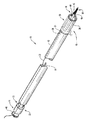
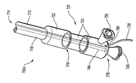
図1を参照すると、参照符号10が付された本発明の搬送装置の例示的な実施形態が示されている。図示されるように、搬送装置10は、遠位端14および近位端16を有するガイド部材12を含む。「ガイド部材」という用語は、患者の体内の曲がりくねった構造内を進むことができるガイドワイヤとして機能することが可能な任意の構造を指すことができる。ガイド部材12は、設計上の問題に応じて中空かまたは部分的に中空でよいことが理解されよう。
Referring to FIG. 1, an exemplary embodiment of a transport device of the present invention, indicated by
ガイド部材12の遠位端14と近位端16との間には管腔18が延びており、その内部には拡張式アセンブリ40およびステント42が配置されている(図2参照)。ガイド部材12の遠位端14は、身体の管腔内への経皮挿入を目的として構成された先端15を含み、一方、近位端16は、アセンブリ40および/またはステント42を展開するようになされた作動アセンブリ20を含みまたはその作動アセンブリ20と協働するようになされている。
A
例示として、ガイド部材12の外径は約0.010インチ(0.25mm)から約0.650インチ(1.65cm)の間でよく、内径または管腔18の直径は約0.004インチ(0.10mm)から約0.55インチ(1.40cm)の間でよい。さらにガイド部材12は、様々に異なる材料から製作することができる。例えばガイド部材12は、Nitinol、鋼、金属、金属合金、複合体、プラスチック、ポリマー、合成材料であって、例えば限定するものではないがPEEKやRydel、またはこれらの組合せから製作することができる。さらにガイド部材12は、ブレード補強ポリマーチューブまたは硬質ポリマーチューブの構成を有するものでよい。さらにガイド部材12は、1つまたは複数の被覆で覆うことができる。例えばガイド部材12は、潤滑性を改善し、血小板凝集を低減し、または抗トロンボゲン性を有する1つまたは複数の被覆を含むことができるが、これらに限定するものではない。上記の他、ガイド部材12は、1つまたは複数の親水性被覆、ヘパリン添加被覆、ポリテトラフルオロエチレン(PTFE)被覆、シリコーン被覆、これらの組合せ、またはガイド部材12を位置決めしかつ/または身体の管腔に対する損傷を防止する助けとなるその他の被覆を含むことができる。
By way of example, the outer diameter of the
任意選択でガイド部材12は、例示的に符号17で示される1つまたは複数の切削部、スリット、溝、またはその他の構造であってガイド部材12の全てまたは一部に柔軟性をもたらす構造を含んでよい。柔軟性をもたらすために切削部、スリット、または溝を使用することについて述べたが、当業者なら、ガイド部材12または装置10のその他の部分が、ガイド部材12の一部および/または装置10のその他の部分に柔軟性をもたらす格子構造を、すなわちそこからガイド部材12または装置10が取り外される部分を有してよいことが理解されよう。
Optionally, the
切削部、スリット、または溝は、ガイド部材12の任意の場所に位置付けることができ、種々の柔軟性が可能になるようにまたは提供されるように様々なピッチで設けることができる。1つまたは複数の溝、切削部、またはスリットは、ガイド部材12の一部を部分的にまたは完全に延びている。さらに、これらの溝、切削部、またはスリットは、ガイド部材12に柔軟性をもたらす限り、直線状、螺旋状、幾何学的、これらの組合せ、または当業者に知られている様々なその他の構成などであってこれらに限定することのない様々に異なる構成を有することができる。さらに、任意の数の溝、切削部、またはスリットを、ガイド部材12および任意選択で拡張式アセンブリ40の部分に含めることができる。例えばより多くの溝、切削部、またはスリットがガイド部材12または拡張式アセンブリ40の一部に含まれるほど、ガイド部材12の柔軟性がより大きくなり、したがって搬送装置10の柔軟性がより大きくなる。同様に、それぞれの溝、切削部、スリットの深さは、所望の柔軟性に応じて様々に異ならせることができる。例えば、溝、切削部、またはスリットが深いほど、ガイド部材12の柔軟性が大きくなり、したがって装置10の柔軟性が大きくなる。さらに、それぞれの溝、切削部、またはスリットの構成を異ならせて、ガイド部材12、したがって装置10の柔軟性に影響を及ぼすことができる。例えば、特定の溝、切削部、またはスリットの内面がより急な勾配になるにつれ、ガイド部材12および/または搬送装置10の柔軟性はより少なくなる。
The cuts, slits, or grooves can be located anywhere on the
図1は、ガイド部材12の先端15に配置された拡張式アセンブリ40およびステント42(図2)を示す。拡張式アセンブリ40は、非外傷性チップ48が終端となる。拡張式アセンブリ40およびステント42は、規制機構または規制部材25によってガイド部材12の先端15に保持される。図1の実施形態で、作動部材28は、規制部材25を作動させるものであり、装置10の近位端に配置された作動アセンブリ20まで延びている。作動部材28は、装置10の近位端まで延びて露出しており、臨床医が作動部材28を近位方向に動かしたときに、規制部材25によって加えられた規制が解除されるようになされている。あるいは作動部材28は、任意選択でガイド部材12の外側を装置10の近位端16まで延ばすことができる。
FIG. 1 shows an
拡張式アセンブリ40は、ガイド部材12の長さに沿って延びる拡張式チューブ44に接続される。拡張式チューブ44を使用して、拡張式バルーン46に流体を充填する。流体は、ガイド部材12の近位端16に位置付けられたルアーロック固定具45を通して導入することができる。いくつかの実施形態では、拡張式アセンブリ40およびステント42を展開するための位置決め部材として、拡張式チューブ44を使用してもよい。さらに、装置10の拡張式アセンブリ40は、拡張式チューブ44によって作動要素21に結合されている。作動要素21をガイド部材12の近位端16に対して滑らせることにより、拡張式アセンブリ40はガイド部材12に対して移動し、ガイド部材12の先端15から展開することができる。本発明のこれらおよびその他の特徴について、以下にさらに詳細に述べる。
The
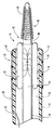
次に図2を参照すると、ガイド部材12の遠位端14は、拡張式アセンブリ40およびステント42が展開するまでそれらを管腔18内に保持するように適合された1つまたは複数の支柱24を含んでいる。各支柱24は、拡張式アセンブリ40およびステント42が解放されるように、外向きに延びるよう付勢されている。それぞれが外向きに延びるよう付勢された支柱24について述べたが、当業者なら、各支柱24を必ずしも外側に延びるように付勢する必要はないことを理解することができる。
Referring now to FIG. 2, the distal end 14 of the
1つまたは複数の支柱24は、様々に異なるプロセスを使用して形成することができる。例えばそのプロセスは、レーザを使用して行われる機械加工プロセス、あるいはハイドロマシニング(hydro−machining)、研削、エンドミル、すりわりのこ、研磨のこ、放電加工機、これらの組合せを含むがこれらに限定されない従来の機械加工プロセス、あるいは1つまたは複数の支柱24を形成するのに十分なスロットまたはスリットを生成することが可能なその他の機械加工プロセスを含むことができるが、これらに限定されない。図2の実施形態では、各支柱24をガイド部材12と一体的に形成することができる。その他の実施形態では、1つまたは複数の支柱24を、ガイド部材12に取着された別個の支柱アセンブリの一部として形成する。
One or
支柱24の周りには規制部材25が配置されている。図2の実施形態では、規制部材25がスリーブ26である。スリーブ26は、支柱24を規制状態または閉じた状態に保持しまたは維持するようになされており、その結果、スリーブ26と支柱24の組合せによって、拡張式アセンブリ40およびステント42が管腔18内に保持される。スリーブ26は、ガイド部材12の外側と協働するようになされており、その結果スリーブ26は近位方向に変位して、支柱24を解放することができる。この例示的な構成において、支柱24は外向きに延びるよう付勢されており、スリーブ26を近位方向に移動させると、支柱24が外向きに延びて拡張式アセンブリ40およびステント42が解放される。
A regulating
スリーブ26は、スリーブ26が確実に支柱24を保持できる限り、様々なタイプの材料から製作することができる。例えばスリーブ26は、低密度ポリエチレン(LDPE)、ポリエチレンテレフタレート(PET)、ポリテトラフルオロエチレン(PTFE)、フッ素化エチレンプロピレン(FEP)、ポリエチレン(PE)、ポリウレタン(PU)、シリコーン管材、およびその他の適切なポリマーまたは合成材料を含むがこれらに限定されない熱収縮合成材料から製作することができる。
The
作動部材28は、スリーブ26から延び、ガイド部材12の外側に沿って配置され、ガイド部材12の開口部30を通り抜ける。作動部材28は、ガイド部材12の近位端16に達するまで、ガイド部材12の管腔18内に沿って進みつづける。その他の実施形態では、作動部材28を、ガイド部材12の管腔18の外側に配置したままでよいことが理解されよう。
The
作動部材28は、スリーブ26を変位させる機能を発揮することができる限り、様々な材料から製作することができかつ様々な構成にすることができる。例えば作動部材28は、プラスチック、ポリマー、金属、複合体、合金、合成材料、およびこれらの組合せから製作することができる。
The actuating
図2に示すように、拡張式アセンブリ40は、拡張式チューブ44に取り付けられた拡張式バルーン46を含む。拡張式チューブ44は、ガイド部材12の遠位端14からガイド部材12の近位端16まで延びている。拡張式チューブ44は、複数の穴50を含んでよい。各穴50および/または複数の穴50は一緒になって、拡張式バルーン46の内部52への流路を形成する。このように、流体は拡張式チューブ44の管腔54に沿って、拡張式バルーン46へと流入する。そのような流体の流れを規制するには、非外傷性チップ48で拡張式チューブ44の遠位端を封止する。穴50は、膨張した拡張式バルーン46への流路を提供する他、収縮した拡張式バルーン46への流路も提供し、または収縮した拡張式バルーン46への流体を除去する。各穴50は、各穴50に流体を通すことができる限り、様々な形状のものでよい。
As shown in FIG. 2, the
拡張式チューブ44は、ある構成の場合、拡張式バルーン46およびステント42を内側で支持する。拡張式チューブ44は、Nitinol、鋼、金属、金属合金、複合材、プラスチック、およびこれらの組合せから製作することができる。さらに拡張式チューブ44は、潤滑性および抗トロンボゲン性を改善し血小板凝集を低減させる1つまたは複数の被覆などであるがこれらに限定することのない、様々に異なる被覆で覆うことができる。その他の被覆には、親水性被覆、ヘパリン添加被覆、ポリテトラフルオロエチレン(PTFE)被覆、シリコーン被覆、またはここに記述される被覆の組合せが含まれるが、これらに限定するものではない。
In some configurations, the
拡張式チューブ44は、様々に異なる構成および実施形態を有することができる。別の実施形態で、拡張式チューブ44は、タフィボルスト(touhy−borst)アダプタなどの環状クランプ装置で拡張式チューブ44を膨張装置に接続させる近位端を含む。あるいは、図1に示すように、拡張式チューブ44の近位端は、ルアー固定具のおす部またはめす部のいずれかのルアー固定具の形をとる。
The
拡張式チューブ44の遠位端には、非外傷性チップ48が取り付けられている。非外傷性チップ48は、拡張式チューブ44の管腔54内に配置され、拡張式チューブ44を封止し、拡張式バルーン46が膨張し収縮する間に流体がそこから逃げるのを防止し、また患者の体内の曲がりくねった構造内に搬送装置10を位置決めしてその内部で慎重に前進させるのを助ける柔軟な先端をもたらす。図示する実施形態で、拡張式チューブ44は拡張式バルーン46の遠位端まで延び、非外傷性チップ48はその内部に配置される。あるいは、拡張式チューブ44は、拡張式バルーン46の遠位端に近接した位置まで延ばすことができ、次いで非外傷性チップ48の一部が、拡張式チューブ44の遠位端から拡張式バルーン46の遠位端の遠位側の位置まで延びる。さらに、別の代替の実施形態では、拡張式チューブ44の末端が、非外傷性チップ48に形成された管腔内にある。
非外傷性チップ48は、柔軟なコイル58で取り囲まれたコア56を含む。図示するように、柔軟なコイル58は、チップ48の遠位端で、はんだボールやチップ48の非外傷性遠位端を形成するその他の機構などの非外傷性部分を末端とする。より一般的には、非外傷性チップ48は、非外傷性チップが柔軟でかつ任意選択で成形可能である限り、様々なその他の構成を有することができる。さらに非外傷性チップ48は、搬送装置10を慎重に前進させならが位置決めすることができると同時に、内科医または臨床医が蛍光透視装置やX線装置などの適切な装置を使用してチップ48の位置を観察することができるように、放射線を通さないものでよい。放射線不透過性を促進させまたはもたらす材料には、白金と、白金、金、またはこれらの組合せの合金と、金属、合金、プラスチック、ポリマー、合成材料、これらの組合せ、または放射線を通さない適切なサインをもたらすその他の材料であって、内科医または臨床医によって成形することが可能な材料を含めることができるが、これらに限定されない。あるいはチップ48は、硫酸バリウムや次炭酸ビスマス、二酸化チタン、またはこれらの組合せなどであるがこれらに限定することのない適切な放射線不透過材料に浸漬させまたはその材料で被覆したポリマーでよい。
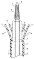
次に図3を参照すると、スリーブ26が近位方向に配置された搬送装置10の遠位端14が示されている。この例示的構成では、支柱24が外向きに広がるよう付勢されているので、拡張式アセンブリ40およびステント42は管腔18内から展開することができる。拡張式アセンブリ40およびステント42の展開は、ガイド部材12を近位方向に配置し、拡張式チューブ44を遠位方向に配置し、または近位方向と遠位方向へのガイド部材12と拡張式チューブ44のそれぞれの動きの組合せにより行うことができる。
Referring now to FIG. 3, the distal end 14 of the
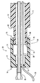
次に図4aを参照すると、展開した形の搬送装置10が概略的に示されており、拡張式アセンブリ40およびステント42が、身体の管腔72の病巣70に展開している。拡張式アセンブリ40およびステント42の展開は、作動アセンブリ20(図1および2)を操作することによって実現できる。病巣70に隣接した場所など所望の位置に拡張式バルーン46およびステント42を展開した後、拡張式チューブ44の管腔54を通して流体を導入し、それによって拡張式バルーン46を広げることができ、したがって図5に示すように、ステント42を身体の管腔72および病巣70の周囲に展開しまたは押しやることができる。
Referring now to FIG. 4 a, the
様々な構成のステント42が当業者に知られている。例えば、拡張式バルーン46の圧力下で自動的に拡張することが可能なステントを使用することができる。別の構成では、図4bに点線で示されるような自己拡張ステントを使用することができる。自己拡張ステントは、支柱24および/または規制部材25によって加えられた規制力を取り除いてガイド部材12をステントに対して近位方向に移動させることにより、自動的に広がる。この場合、自己拡張ステントは、図4bに示すように拡張式バルーン46を取り囲んでおり、あるいはステントは、符号46bが付された点線で示されるように、拡張式バルーン46をステントに対して近位方向に位置付けた状態でかつ拡張式チューブ44に取り付けたままの状態で、拡張式チューブ44を取り囲むことができる。拡張式バルーンを取り巻くようステントのサイズを縮小することができる限り、また搬送装置10のガイド部材12の内部にステントを配置することができる限り、本発明と共に様々なステントを使用することができる。
Various configurations of
次に図6を参照すると、拡張式バルーン46およびステント42を展開するのに使用することができる作動アセンブリ20の、例示的な実施形態が示されている。作動アセンブリ20を操作することによって、拡張式アセンブリ40およびステント42は、ガイド部材12の遠位端14で規制構成から解放される。より詳細には、拡張式アセンブリ40の一部を形成する拡張式バルーン46は、拡張式バルーン46の実質的に周りに配置されたステント42と共に展開することができる。
Referring now to FIG. 6, an exemplary embodiment of an
図示されるように、作動部材20は、拡張式チューブ44の近位端に結合された作動要素21を含む。作動要素21は、ガイド12の近位端16に取り付けられかつ協働するように構成された遠位端74を含む。作動要素21の近位端76は、拡張式チューブ44の近位端に取着され、一方、作動部材28の近位端は、封止された作動要素21の開口部47を通過する。この例示的な実施形態で、拡張式チューブ44の近位端は、様々な相補形のルアー固定具を取着することが可能なルアー固定具45を含む。例えばルアー固定具45には、拡張式バルーン46を膨張させ収縮させる間、拡張式バルーン46(図5)に流体を導入しまたそこから流体を除去するための注射器(図示せず)を取着することができる。ルアーフィティング45の使用について述べたが、当業者なら、様々なその他のフィッティング構成を拡張式チューブ44の近位端に取着できまたは形成できることを理解することができる。
As shown, the
作動要素21は、拡張式アセンブリ40およびステント42を展開するために、遠位方向に変位するよう適合される。作動要素21の位置決めを助けるため、遠位端74は、ステップ構成を有することができ、またガイド部材12の近位端16に形成された相補形の窪み80に嵌合する突起78を含むことができる。突起78および窪み80は、ガイド部材12の遠位端14に対する拡張式アセンブリ40およびステント42の相対的な位置を示す。したがって作動要素21および/またはガイド部材12は、1つまたは複数の突起および窪みを含んでよい。作動要素21が遠位方向に変位すると、突起78は窪み80に嵌合する。ガイド部材12の管腔18を封止するには、1つまたは複数の封止材84で突起78を取り囲む。さらに、1つまたは複数の封止材(図示せず)は、拡張式チューブ44および/または作動部材28を取り囲むことができる。例示として、各封止材は、1つまたは複数のOリングが1つまたは複数の溝に嵌まったもの、1つまたは複数のOリング、ガスケット、または粘性流体封止材でよい。
Actuating
作動要素21を遠位方向に変位させると、遠位端74は、ガイド部材12に形成された壁面またはストッパ82に接触し、作動要素21が遠位方向にさらに変位することができない。この構成によって、作動要素21は、遠位に向かって長手方向に過度に変位することができない。作動要素21の長手方向への変位がこのように停止することは、拡張式バルーン46およびステント42がガイド部材12の管腔18内から所望の位置まで展開して、ステント42を広げまたは埋め込んだことを示している。
When the
ステント42の特定の位置付けを示す1つの手法について述べたが、当業者なら、様々な異なる実施形態を特定することができる。例えば、作動要素21、したがってステント42が変位する距離を制御するために、複数の窪みおよび/または突起を作動要素21およびガイド部材12の内部に含めることができる。別の構成では、作動要素21に形成された壁面またはストッパをガイド部材12の遠位端に嵌合して、遠位に向かって長手方向に過度に変位するのを防止することができる。さらに別の構成では、作動要素21とガイド部材12の1つまたは複数の壁面またはストッパの組合せを使用することができる。さらに別の構成では、作動要素21の遠位端74を先細りにして、ガイド部材12の近位端16に形成されたテーパ部と協働させることができる。相補形のテーパ部は、ガイド部材12の近位端16に対する作動要素21の長手方向の変位を制御する。さらに別の構成では、窪み、突起、壁面、ストッパ、ねじ山、またはテーパの組合せを使用することができる。様々なその他の手法は、ステント42の位置を示しつつ作動要素21が移動する距離を制御することで知られている。
Although one approach for indicating a particular positioning of the
上記の他、作動要素21は、ガイド部材12の近位端16に取着されまたは結合された別個の要素または部材に壁面またはストッパ82および窪み80が形成されるように、1つまたは複数の要素を含んでよいことを理解することができる。このようにすることにより、作動要素21をガイド部材12とは個別に製作することができ、それによって、ガイド部材12の近位端16を所望の構成に製作する際のコストおよび費用を削減することができる。
In addition to the above, the
図7から図24までは、規制機構25に関する代替の実施形態を示す。図7から図24までに示される搬送装置の数多くの特徴は、搬送装置10に関する構造および機能と実質的に同様であることが理解されよう。したがって本発明の一実施形態の特徴および機能は、本発明のその他の実施形態に適用可能である。
7 to 24 show alternative embodiments relating to the
次に図7および8を参照すると、本発明の搬送装置100の別の例示的な実施形態が示されている。図示されるように、ガイド部材112は、本明細書で述べるその他のガイド部材と同様でよく、遠位端114、近位端(図示せず)、および遠位端114から近位端まで延びる管腔118を有する。ガイド部材112の先端115は、複数の支柱124、例えば2つ以上の支柱を含む。各支柱124は、各支柱124が規制部材125から解放されたとき、各支柱124の遠位端がガイド部材112の縦軸に対して外向きに動くように、任意選択で付勢することができる。支柱124のそれぞれが付勢される状態について述べたが、当業者なら、これら支柱124のうち1つまたは複数を付勢できることが理解されよう。
Referring now to FIGS. 7 and 8, another exemplary embodiment of the
図8に示すように、参照符号124aで示される少なくとも1つの支柱を、ガイド部材112の縦軸に向けて付勢する。図7により明確に見られるように、支柱124aには、非外傷性チップ148が配置されている。この非外傷性チップ148は、単独でまたは支柱124aと組み合わせて、身体の管腔内に挿入する前に内科医または臨床医により成形可能なものでよい。このように内科医または臨床医は、ガイド部材112を患者の体内の曲がりくねった構造内にガイドすることが可能な、例えば「J」字形などであってこれらに限定することのない適切な形状にチップ148を構成することができる。非外傷性チップ148の全てまたは一部は、白金、白金合金、放射線不透過材料、放射線不透過材料に浸漬しまたはその材料で被覆された材料、金属、合金、プラスチック、ポリマー、合成材料、これらの組合せ、あるいは、適切な放射線不透過のサインをもたらすと同時に単独であろうと支柱124aとの組合せであろうと内科医または臨床医が成形することが可能なその他の材料から製作することができる。この構成では、非外傷性チップ148が搬送装置100の非外傷性チップとして機能することができるので、拡張式アセンブリを接続したガイドワイヤを、そのガイドワイヤの遠位端が任意選択で柔軟な非外傷性チップを含んだ状態で管腔118内に配置することができる。
As shown in FIG. 8, at least one support column indicated by
規制位置に支柱124を維持するため、すなわちガイド部材112から外向きに広がらないようにするため、規制部材125で支柱124を取り囲む。規制部材125および本明細書で述べるその他の規制部材または機構は、1つまたは複数の支柱に規制力を加えるための手段、あるいはガイド部材の遠位端に規制力を加えるための手段の例である。この実施形態で、規制部材125は、ガイド部材112の遠位端から近位端まで完全にまたは部分的に延びることができる。例えば規制部材125は、実質的に支柱124のみを取り囲むことができ、または図9〜24に示すものと同様の構成を持つことができる。
In order to maintain the
図7および8に示す構成では、規制部材125または規制力を加えるための手段がカテーテル127であり、これが支柱124に力を加えて支柱124が外向きに広がるのを防止し、または支柱124に力を加えて拡張式アセンブリ140およびステント142を管腔118内に維持する。カテーテル127に対してガイド部材112を変位させることによって、またはガイド部材112に対してカテーテル127を変位させることによって、支柱124に加えられた力を取り除き、またある構成では、支柱124の遠位端を外向きに動かして、拡張式アセンブリ140およびステント142を展開させる。
7 and 8, the restricting
上述のように、カテーテル127は、ガイド部材の長さに沿って完全にまたは部分的に延びることができる。別の構成では、カテーテル127を、遠位端からガイド部材112の近位端に向けて完全にまたは部分的に延びるスリーブまたはその他の構造に置き換えることができる。これら代替の構成は、本明細書で述べるような規制力を加える手段でもある。このような規制部材または機構は、放射線を通さないものでよく、あるいは装置の位置決めを助ける1つまたは複数の放射線不透過マーカーを含む。さらにこれらの規制部材または機構は、ガイド部材の外側、ガイド部材の管腔内、またはガイド部材の管腔内に部分的にかつガイド部材の外側に部分的に配置された作動部材および/または作動アセンブリを使用することにより、ガイド部材に対して滑動可能である。作動アセンブリは、その構造および機能が、図6に示す作動アセンブリ20または本明細書で述べる任意のその他の作動アセンブリと同様でよい。したがって、本発明のシステム、方法、および装置は、1つまたは複数の支柱あるいはガイド部材の遠位端を規制するという所望の機能を発揮させるため、任意選択でカテーテル、スリーブ、バンド、または本明細書で述べるその他の構造を交換可能に使用することができる。
As described above, the
図9および10は、本発明の搬送装置200の別の実施形態を示す。図示されるように、搬送装置200は、複数の支柱224が遠位端214に配置されているガイド部材212を含む。支柱224は、規制部材225を使用して規制位置に維持される。この実施形態で、規制部材225は、支柱224を取り囲むスリーブ226である。スリーブ226は、支柱が外向きに広がらないように、あるいは管腔内に拡張式バルーンおよび/またはステントが維持されるように、支柱に力を加える規制部材または機構として働く。
9 and 10 show another embodiment of the
支柱224は、規制位置にあるとき、拡張式アセンブリ240およびステント240をガイド部材212の管腔218内に維持する。スリーブ226の内部、またはスリーブ226とガイド部材212との間には、1つまたは複数の作動部材228が配置されている。作動部材228は、任意選択で規制機構または部材の一部を形成するものであり、各支柱224の近位端に近接した符号Aで示される位置で、ガイド部材212に取着している。作動部材228は、スリーブ226の遠位端から遠位方向に延び、さらにスリーブ226の外側を通り近位方向へと延びて、装置200の近位端(図示せず)を終端とする。各作動部材228の一端は、スリーブ226の一部を形成しようとスリーブ226に取着されていようと、またはガイド部材212に取着されていようとあるいはこれらを組み合わせたものであろうと、スリーブ226の近位端に位置付けられているので、作動部材228を近位方向に変位させることによって、作動部材228は、点線で示されるようにスリーブ226を1つまたは複数の部分232に優先的に分離する。このようにすることによって、図10に示すように、支柱224は解放される。
The
作動部材228を作動させるには、ガイド部材212の管腔218内を通してまたは通さずに、作動部材228の近位端(図示せず)をガイド部材212の近位端(図示せず)まで延ばす。作動部材228は、図6の作動アセンブリや、本明細書に記載されかつ本明細書に含まれる教示に照らして当業者に理解されるその他の作動アセンブリなどであって、しかしこれらに限定するものではない作動アセンブリの、作動要素(図示せず)まで延ばすことができる。作動部材228は、ガイド部材212に対して近位方向に変位させることができる。このようにすることによって、スリーブ226により加えられた規制力が解除され、支柱224が外向きに広がり、拡張式アセンブリ240および/またはステント242が展開する。
To actuate the actuating
スリーブ226は、それを作る材料が支柱224を固定するのに十分強力なものであると同時に作動部材228の動作によって優先的に分離するよう構成される限り、様々な異なる材料から形成することができる。例えばスリーブ226は、低密度ポリエチレン(LDPE)、ポリエチレンテレフタレート(PET)、ポリテトラフルオロエチレン(PTFE)、フッ素化エチレンプロピレン、ポリエチレン(PE)、ポリウレタン(PU)またはシリコーンの管材を含むがこれらに限定されない熱収縮合成材料から製作することができる。
The
1つまたは複数の作動部材228は、この作動部材228に使用される材料が、本明細書に開示される作動アセンブリなどであってそれに限定するものではない作動部材228を破損することなく近位方向に変位させるのに十分強力である限り、様々な異なる材料から形成することができる。例えば作動部材228は、プラスチック、ポリマー、金属、複合材、合金、合成材料、およびこれらの組合せから製作することができる。
The one or
作動部材228を使用する代わりに、本発明の実施形態は、スリーブ226を優先的に分離する様々なその他の手段を使用することができる。例えばスリーブ226は、搬送装置が配置されている身体の管腔内の流体との化学反応によって溶解する溶解性の化学結合、あるいは抵抗加熱、超音波、または高周波エネルギーを、作動部材228および/または装置200が入っている身体の管腔内の領域、特に材料がスリーブのその他の領域またはゾーンよりも弱い強度を有する破断または切断領域またはゾーンに加えることによって破断する結合、あるいはこれらの組合せを有することができる。
Instead of using the
次に図11から14まで参照すると、規制部材または機構325の別の実施形態を有する搬送装置300の実施形態が示されている。この実施形態で、規制部材325は、ガイド部材312の1つまたは複数の支柱324を取り囲んで支柱324に対して規制力を加え、それによって支柱324を規制状態に維持するように適合されたスリーブ326の形をとる。スリーブ326は、第1の面364と第2の面366を、これら第1および第2の面364、366が中間部分368によって分離された状態で含んでいる。中間部分368は、この中間部分368の一部がガイド部材312と互いに接触するように、または互いに並置されるように、または互いに連続するように、または互いに隣接するように、ガイド部材312を取り囲む。作動部材328は、そのような中間部分368の一部を通過して、ガイド部材312にスリーブ326を固定する。支柱324に対して規制力を加えるのをさらに助けるため、第1の面364と第2の面366とを折り重ねて、スリーブ326の外面のそれぞれの部分に取着するようにする。
Referring now to FIGS. 11-14, an embodiment of a
図11の規制部材または機構を形成するプロセスを、図12および13に示す。まず図12を参照すると、作動部材328を結合する前の開いた状態のスリーブ326が示されているが、スリーブ326は、ガイド部材312の表面に直接形成することができ、あるいは別個の管状部材の表面に形成した後にガイド部材312に取着しまたは結合することができる。スリーブ326は、略多角形の形状を持つものが示されているが、当業者なら、スリーブ326は、ここで述べる機能を発揮することが可能である限り、様々なその他の構成を有してよいことを理解することができる。この例示的な構成では、スリーブ326をガイド部材312に直接結合する。図13に示すように、中間部分368の一部が中間部分368の別の部分に近接した状態になるまで、スリーブ326の第1の面364および第2の面366をガイド部材326の少なくとも一部に巻き付ける。あるいは、第1の面364を第2の面366に接触させ、あるいは第2の面366と並置し、連続させ、または隣接させることができる。
The process of forming the regulating member or mechanism of FIG. 11 is shown in FIGS. Referring first to FIG. 12, an
中間部分368の一部が互いに近接している場合、図13に示すように、作動部材328あるいはその他の作動部材がスリーブ326のそれぞれの部分を縫合して、中間部分368のそれらの部分を結合する。作動部材328を実質的に真っ直ぐに引っ張り、またはその他の方法でスリーブ326内を通るように位置決めすると、図11に示すように、第1の端部364と第2の端部366のそれぞれが折り曲げられて、スリーブ326の外面にそれぞれ取着される。
When portions of the
図14に示すように代替の構成では、スリーブ326が、中間部分368の一部に、作動部材328を受容する複数の開口部360を含むことができる。このように作動部材328は、スリーブ326を縫合していくのではなく、開口部360を通過することができる。別の実施形態では、第1の端部364または第2の端部366をスリーブ326の外面に取着せずに、スリーブ326の第1の端部364をスリーブ326の第2の端部364に結合することができる。さらに別の構成では、第1の端部364の一部を第2の端部366に重ねることができ、またはその逆を行うこともできる。あるいは、第1の端部364と第2の端部366とを互いに接触させるが重ねることはしない。同様に、第1の端部364と第2の端部366を互いに近接させ、互いに隣接させ、互いに連続させ、または互いに並置することができる。
In an alternative configuration, as shown in FIG. 14, the
図11〜14に関して述べた規制部材または機構を作動させるには、作動部材328の近位端を、ガイド部材312の管腔内またはその管腔を通さずに、ガイド部材321の近位端まで延ばす。作動部材328をガイド部材312に対して近位方向に変位させることにより、またはその逆を行うことにより、またはこれらを組み合わせて行うことにより、作動部材328は、スリーブ326の少なくとも一部を通して配置された状態から解放される。このようにすることで、スリーブ326によって加えられた規制力が解除され、支柱324が外向きに広がり、拡張式アセンブリおよび/またはステントが展開する。臨床医または内科医は、直接または作動機構または装置を使用することによって、作動部材328を長手方向に動かし始めることができる。
To operate the restricting member or mechanism described with respect to FIGS. 11-14, the proximal end of the actuating
スリーブ326は、その材料が1つまたは複数の支柱324を規制するのに十分強力である限り、様々な異なる材料から形成することができる。例えばスリーブ326は、熱収縮プラスチックやポリマー、低密度ポリエチレン(LDPE)、ポリエチレンテレフタレート(PET)、ポリテトラフルオロエチレン(PTFE)、フッ素化エチレンプロピレン(FEP)、ポリエチレン(PE)、ポリウレタン(PU)、シリコーン管材などであってこれらに限定されない様々なタイプのポリマーまたはシリコーンフィルムから製作することができる。
The
作動部材328は、その使用される材料が、本明細書に開示される作動アセンブリで作動部材328を破損せずにこの部材を近位方向に変位させるのに十分強力である限り、様々な異なる材料から形成することができる。例えば作動部材328は、プラスチック、ポリマー、金属、複合材、合金、合成材料、これらの組合せ、または、スリーブ326を通して配置させる機能を発揮することが可能でありまたはそこから引き出すことが可能であるその他の材料から製作することができる。
Actuating
次に図15〜19を参照すると、規制部材または機構の代替の構成を有する搬送装置400の別の実施形態が示されている。この特定の実施形態は、作動部材438を備えたヒンジ構成を有する規制部材または機構425を利用し、このヒンジ構成は、任意選択で規制部材または機構425の一部を形成し、またガイド部材の一部を保持しまたは規制する状態になるように規制部材のヒンジ部分を維持するためのピンとして働く。
Referring now to FIGS. 15-19, another embodiment of a
図15に示すように、規制部材425は、作動部材428を受容するようになされた複数のチャネル464a〜464fを有するスリーブ426である。スリーブ426の第1の面466と第2の面468の両方は、いくつかのチャネル464a〜464fで、すなわち第1の面466のチャネル464a、464c、および464eと第2の面468のチャネル464b、464d、および464fで形成される。作動部材428が第1の面466のチャネルを通過した後に第2の面468のチャネルを通過するように、作動部材428をチャネル464a〜464fに順に通すことによって、第1の面466は第2の面468に結合され、スリーブ426はガイド部材412の支柱424に対して規制力を加える。
As shown in FIG. 15, the restricting
図15の規制部材または機構を形成する例示的なプロセスを、図16〜19に示す。まず図16を参照すると、作動部材428を結合する前の開いた位置にあるスリーブ426が示されており、スリーブ426は、いくつかの延長部またはトング460a〜460fを含んでいる。これらの延長部460a〜460fは、チャネル464a〜464fを形成するように、かつ作動部材428が内部に位置付けられたガイド部材412などであってこれに限定されない管状部材またはチューブを取り囲むように構成される。
An exemplary process for forming the restriction member or mechanism of FIG. 15 is shown in FIGS. Referring first to FIG. 16, the
ガイド部材412にスリーブ426を取着するため、スリーブ426をガイド部材426の所望の位置に位置付ける。作動部材428は、図17〜19に示すように、ガイド部材412に近接させた状態で配置する。延長部460a〜460fの端部は、図18に示すように、ガイド部材412と作動部材428との間に挿入する。あるいは、延長部460a〜460fの端部を部分的にガイド部材412に巻き付け、作動部材428をこれら部分的に巻き付けた延長部460a〜460fに接触するよう配置することができる。
To attach the
延長部460a〜460fをガイド部材412および作動部材428の周りに緊密に巻き付けた後、図15および19に示すように、各延長部460a〜460fの端部を作動部材428上に折り重ねてスリーブ426の外面に取着する。このようにしてチャネル464a〜464fが形成され、スリーブ426は、作動部材428と共に、ガイド部材412のスリット424を解放可能に規制するよう構成される。
After the
単独でまたは作動部材428との組合せでスリーブ426によって加えられた規制力の解除は、ガイド部材412に対して長手方向に作動部材428を変位させることにより、またはその逆を行うことにより、またはその組合せにより実現される。作動部材428はチャネル464a〜464fから解放されて、支柱424の付勢力により支柱を外向きに広げ、拡張式アセンブリおよび/またはステントを展開する。臨床医および内科医は、直接あるいは作動機構または装置を使用することによって、作動部材428を長手方向に動かし始めることができる。
The release of the regulatory force applied by the
次に図20を参照すると、本発明の規制部材または機構525の別の実施形態を有する別の搬送装置500が示されている。規制部材525は、いくつかのフープ564a〜564nを形成するコード529を含む。フープ564a〜564nの1つまたは複数は、任意選択で規制部材または機構525の一部である作動部材528を受容するようになされている。作動部材528は、コード529がガイド部材512の支柱524に対して規制力を加えることができるように、フープ564a〜564n内に配置される。作動部材528は、フープ564a〜564nから除去することができ、それによって、支柱524を外向きに広げて拡張式アセンブリおよび/またはステントを展開することができる。コード529は、金属ワイヤ、ポリマー作動部材、あるいは作動部材または固定部材が通るフープが形成されるよう操作することができるその他の材料から作製することができる。任意選択でコード529は、1つまたは複数の支柱の影響下で、あるいは加えられた付勢力によって、あるいはコード、フープ、および/または規制部材の構成および/または材料によりコード520に組み込まれた付勢力によって、外向きに広がるよう適合される。
Referring now to FIG. 20, another
コード529は、様々な取着機構を介して、ガイド部材512および/またはそれに結合された支柱の1つまたは複数に取着することができる。例えばコード529は、接着剤、機械式ファスナ、固定ループ、あるいはコード529をガイド部材512および/または支柱524の1つまたは複数に確実に取着させるその他の手法によって、ガイド部材および/または1つまたは複数の支柱に取着することができる。あるいはコード529は、作動部材528に取着して、作動部材528を近位方向に動かしたときに取り外すことができる。臨床医または内科医は、直接あるいは作動機構または装置を使用することにより、作動部材528を長手方向に動かし始めることができる。
The
次に図21〜24を参照すると、本発明の規制部材または機構625の別の実施形態を有する別の搬送装置600が示されている。図示するように、ガイド部材612は、ガイド部材612の管腔618内に配置されたステントおよび拡張式バルーンの展開が可能になるよう外向きに広がるようになされた複数の支柱624を含む。規制部材625は支柱624を規制する。この規制部材625は、ある構成において、フラップ660および662で構成された柔軟な部材627である。フラップ660および662は、図23に示すように、2つの隣接する支柱624aと624bとの間のギャップ664の間を延び、支柱624の周りに巻き付いて管腔618内のステント(図示せず)および拡張式バルーン(図示せず)を圧縮するようになされている。これらのフラップ660および662は、支柱624aおよび624bに結合されまたはその他の方法で接続された2つの別個の部材、あるいはフラップ660および662を形成しながら支柱624aおよび624bに結合された単一部材でよい。
Referring now to FIGS. 21-24, another
支柱624が確実に保持されるようにフラップ660および662を位置決めしたら、図23に示すように位置666でフラップを作動部材628で縫合する。この作動部材628は、任意選択で規制部材または機構の一部を形成するものであり、図6で述べた作動アセンブリや本明細書に含まれる教示に照らして当業者に知られるその他の作動アセンブリなどであってこれらに限定されない作動アセンブリに向かい、搬送装置600の長さに沿って延びる。臨床医または内科医は、直接あるいは当業者に知られる作動機構または装置を使用することによって、規制部材または機構625が解放されるように作動部材628を長手方向に動かし始めることができる。
Once the
作動部材628を使用してフラップ660および662を結合した後、図24に示すように、フラップ660および662を支柱624とフラップ660および662の残りの部分の周りで折り返し、次いで支柱624またはガイド部材612のその他の部分に取着する。作動部材628を近位方向に変位させると、フラップ660および662が解放され、支柱624が外向きに広がるにつれてステント(図示せず)および拡張式バルーン(図示せず)が展開する。
After actuating
次に図25を参照すると、搬送装置700aの近位端の例示的な実施形態が示されている。本発明の搬送装置のその他の実施形態で論じた特徴および構造は、搬送装置700aに当てはまる。
Referring now to FIG. 25, an exemplary embodiment of the proximal end of the
図示されるように、ガイド部材712の近位端716は、ガイド部材ハウジング722を終端とする。このガイド部材ハウジング722は、ガイド部材712と一体的に形成することができ、あるいはガイド部材712の近位端に結合し、接続し、または取着された個別の部材でよい。ガイド部材712の近位端716は、作動アセンブリ720の作動要素721に結合することができる。この作動要素721は、ガイド部材ハウジング722に滑動可能に係合する。作動要素721を操作することによって、拡張式バルーン(図示せず)が取り付けられている拡張式チューブ744を移動させる。作動部材728は、作動部材728が滑り込むことのできる封止材(図示せず)が適合された作動部材721の開口部786を通り抜ける。このように、開口部786および封止材(図示せず)によって、操作者は、搬送装置700aの遠位端714に配置された1つまたは複数の支柱(図示せず)を規制する規制部材(図示せず)を解放しまたは変位させることが可能になる。封止材は、ポリウレタンやシリコーンゴム、または作動部材728の周りを封止することができかつその内部に作動部材728を滑り込ませると同時に流体封止が維持されるその他の材料などであってこれらに限定されないポリマーガスケットを含むことができる。
As shown, the
拡張式チューブ744は、任意選択で図1の拡張式チューブ44と同様の構成を有するものであり、ガイド部材712の遠位端714からガイド部材ハウジング722を通って伸び作動部材721の近位端776を終端とし、そこに取着される。図示されるように、作動要素721の近位端776はルアー固定具745を含み、これは相補形のルアー固定具と協働するように適合されており、ガイド部材712の遠位端714に配置された拡張式バルーン(図示せず)を膨張させ収縮させる。
The
この例示的な実施形態では、追加のルアー固定具790を作動部材721内に形成しまたは作動部材721に結合する。ルアー固定具790を設けることにより、流体をガイド部材712の管腔718内に流入させ、それによって、装置が脈管構造内を前進するときに、その装置近傍の血流に造影剤を導入することが可能になる。
In this exemplary embodiment, an
次に図26を参照すると、搬送装置700aの代替構成が、例示的な搬送装置700bとして示されている。この構成で、作動要素721とガイド部材ハウジング722との係合は、作動要素721とガイド部材ハウジング722に形成された相補形のねじ山792によって実現することができる。これら相補形のねじ山792は、作動要素721の回転運動によって、またはガイド部材712の縦軸に並行な運動によって、ガイド部材ハウジング722に対して作動部材721を長手方向に動かすことができるように構成することができる。ねじ山792を使用することによって、ガイド部材712の遠位端714に配置された拡張式バルーン(図示せず)およびステント(図示せず)の長手方向を動きを、非常に精密に制御することができる。
Referring now to FIG. 26, an alternative configuration for the
相補形のねじ山を使用することについて述べたが、当業者なら、本明細書に含まれる教示に照らし、ガイド部材ハウジング722に対して作動要素721を長手方向に制御可能に動かすことのできる様々なその他の構造を使用できることが、理解されよう。例えば作動要素721は、ガイド部材ハウジング722に形成されたキー溝に一致するキーを含むことができ、あるいはその逆も可能である。さらに、回転運動と拡張式バルーンおよびステントの長手方向の動きに並行な運動について述べたが、当業者なら、拡張式バルーンおよび/またはステントの展開を可能にしまたは容易にすることができる様々なその他の方向の運動を特定することができる。例えば作動要素の運動は、ガイド部材に対して作動要素が1回回転しまたは複数回回転するか否かに関わらず、ガイド部材の縦軸に対して任意の角度の方向に進むものでよい。
Although the use of complementary threads has been described, those skilled in the art will be able to variously controllably move the
図27に示すように、搬送装置700cの別の実施形態が例示されている。ガイド部材ハウジング722に対する作動要素721の移動を助けるため、作動要素721およびガイド部材ハウジング722および/またはガイド部材712は、それぞれ任意選択のハンドル796および798を含むことできる。これらのハンドル796および798は、1つまたは複数の装置のユーザ付加物と協働するようになされた把持領域を、任意選択で含むことができる。別の構成では、ハンドル796および798のそれぞれは、その長さに沿って実質的に一定の断面を有することができる。さらに別の構成では、ハンドル796および798のそれぞれは、その長さに沿って断面積が変化するものでよい。さらに、図27には単一のルアー固定具745が示されているが、当業者なら、搬送装置の内部または拡張式バルーンに1種または複数の流体を容易に導入させるため、搬送装置700cが1つまたは複数のフィッティングを含んでよいことが理解されよう。
As shown in FIG. 27, another embodiment of a transport apparatus 700c is illustrated. To assist movement of the
図28は、搬送装置700dのさらに別の実施形態を示し、作動要素721は、ガイド部材712の近位端に形成された相補形の部品または構造770と協働するようになされた回転ギア762が収められている、ハウジング760を含む。ギア762は、関連する1つまたは複数の歯、部品、または構造体768を備えるものであり、このギアは、臨床医またはその他の個人がアクチュエータ部材766を選択してアクチュエータ764を回転することによりギア762を回転させるので、アクチュエータ764によって操作しまたは回転させることができる。任意選択で、アクチュエータ764は、ギア762と協働することができる1つまたは複数の歯、部品、または構造体を任有し、したがってアクチュエータ764の回転運動はギア762の運動に変換される。
FIG. 28 shows yet another embodiment of a
アクチュエータ764、したがってギア762が回転するにつれ、ガイド部材712の相補形部品770はギア762の歯、部品、または構造768と噛み合うようになり、アクチュエータ764の回転方向に応じてガイド部材712を近位方向および/または遠位方向に移動させる。このようにすることによって、拡張式アセンブリおよびステントを装置700dの遠位端(図示せず)から展開することができる。
As the
ガイド部材712を移動しまたは位置決めする他、作動部材728は、ハウジング760および作動要素721に関連付けられたスライドスイッチ762を使用することによって操作することもできる。作動部材728は、スイッチ762に取着されたレッグ762に結合しており、一方スライドスイッチ762は、ハウジング760に滑動可能に結合されている。スイッチ762の滑り並進運動によって、作動部材728は、装置700cの規則部材または機構(図示せず)によって加えられた規制力が解除されるようにそれぞれの方向に移動する。当業者なら、本明細書に含まれる教示に照らし、作動要素721の様々なその他の構成を明らかにすることができる。
In addition to moving or
次に図29〜37を参照すると、本発明による搬送装置の代替の実施形態の、様々な構成が示されている。その他の記載されている搬送装置の特徴および機能は、搬送装置800aから800gに関する考察に当てはまる。さらに、搬送装置800aに関して述べた特徴および機能の大部分は、以下にさらに述べる搬送装置800bから800gにも当てはまることが理解されよう。図29〜37の搬送装置は、ガイドワイヤと共に搬送装置を使用するように適合された様々な実施形態を示す。説明を簡単にするために、図29〜37の実施形態は、ガイド部材内部の拡張式アセンブリおよびステントを規制する規制部材または機構を含んでいない。しかし、本明細書に記載されまたは当業者に理解される任意の作動アセンブリを備えた任意の規制部材または機構を、装置800a〜800gに使用できることが理解されよう。 Referring now to FIGS. 29-37, various configurations of alternative embodiments of a transport apparatus according to the present invention are shown. Other described transport device features and functions apply to the discussion regarding transport devices 800a-800g. Furthermore, it will be appreciated that most of the features and functions described with respect to transport device 800a also apply to transport devices 800b to 800g, described further below. The transport device of FIGS. 29-37 illustrates various embodiments adapted to use a transport device with a guidewire. For ease of explanation, the embodiment of FIGS. 29-37 does not include an expandable assembly within the guide member and a restricting member or mechanism that restricts the stent. However, it will be appreciated that any restriction member or mechanism with any actuation assembly described herein or understood by one of ordinary skill in the art can be used for the devices 800a-800g.
図29に示すように、搬送装置800aは、近位端816および遠位端814を有するガイド部材812を含み、遠位端814から近位端816に向かって管腔818が延びている。遠位端814は、本明細書で述べるその他のガイド部材の遠位端と同様の構成を有することができる。例えば拡張式アセンブリ840および/またはステント842を規制するように適合された構造と協働するように、遠位端814に規制部材(図示せず)を配置することができる。近位端816には、図6に関して述べたものと同様の手法で、作動アセンブリ820の作動要素821と協働するガイド部材ハウジング822が配置されている。
As shown in FIG. 29, the delivery device 800 a includes a
ガイドワイヤ832は、作動要素821の近位端の開口部834からガイド部材812の遠位端814に向かって延びている。図30に最もよく示されるように、ガイドワイヤ832は、ガイド部材812の遠位端に配置された拡張式アセンブリ840と協働する。この例示的な構成で、拡張式アセンブリ840は、管状部材836、すなわちそこに結合されまたは取着された拡張式バルーン846と協働する管状部材836を含む。管状部材836は、拡張式アセンブリ840およびステント842の展開を容易にする位置決め部材として機能することができる。ガイドワイヤ832は管状部材836内を延びており、必要な場合に拡張式バルーン846および拡張式バルーン846に結合されたステント842をガイドワイヤ832に沿って移動させる。管状部材836の管腔の内径は、ガイドワイヤ832の外径に適合するものである。
The
ガイドワイヤ832は、その遠位端が、コイルばね858を巻き付けた心線856を含んでよい非外傷性チップ848で終わっている。心線856は、ガイドワイヤ832の残りの部分を延長したものでもよいし、あるいはガイドワイヤ832の遠位端に結合されまたは取着された個別の部材でもよい。どちらの場合でも、心線856は、ガイドワイヤ832と同じかまたは異なる材料から作製することができ、任意選択で中実部材または管状部材にすることができる。
The
拡張式アセンブリ840の拡張式バルーン846は、拡張式バルーン846から延びてルアー固定具845を備えた作動要素821の近位端で終わる拡張式チューブ844によって膨張する。作動要素821に取着した状態で追加のルアー固定具890を設けることができる。ルアー固定具890は、ルアー固定具790と実質的に同じ機能を発揮できることが理解されよう。
The
拡張式チューブ844の遠位端は、拡張式バルーン846の内部と協働する。拡張式チューブ844の遠位端は、管状部材836、拡張式バルーン846、または管状部材836と拡張式バルーン846の両方に接続することができる。処置の間、拡張式チューブ844を使用して、拡張式バルーン846および/またはステント842を位置決めすることができる。したがって拡張式チューブ844は、拡張式チューブ844の遠位方向への運動を拡張式アセンブリ840の残りの部分の遠位方向への運動に変換するのに十分な強度を有することができる。同様に拡張式チューブ844は、拡張式チューブ844の近位方向への運動を拡張式アセンブリ840の残りの部分の近位方向への運動に変換するのに十分な強度を有することができる。
The distal end of the
搬送装置800aは、ガイドワイヤ832を身体の管腔内に位置決めすることができるように構成され、かつ搬送装置800aは、ガイドワイヤ832を所望の位置に維持しながら身体の管腔内から取り出すことができる。したがって、その他の従来のインターベンショナルな装置を使用して、この処置を完了することができる。以下により詳細に論じるように、ガイドワイヤの遠位端には、例えば、ステント操作中に身体の血管内で遊離した塞栓性粒子を収集するフィルタアセンブリなどの装置を接続することができる。当業者に理解されるように、その他の装置をガイドワイヤ832に導入することができる。
The delivery device 800a is configured to allow the
図31には、装置800bである別の実施形態が示されている。この装置800bは、ガイドワイヤ832と協働するようになされた拡張式アセンブリ840bを含む。図示されるように、拡張式アセンブリ840bは、膨張性の拡張式バルーン846と協働する管状部材836を含む。管状部材836の近位端には、位置決め部材838が配置されている。位置決め部材838は管状部材836の近位端に結合されており、位置決め部材838によって加えられた力が容易に管状部材836に伝わって、拡張式アセンブリ840を位置決めする。位置決め部材838は、その結合または取着が、管状部材836および/または拡張式バルーン846の近位端、遠位端で生じようと、あるいは管状部材836および/または拡張式バルーン846のそれぞれの近位端と遠位端の間のその他の部分で生じようと、管状部材836、拡張式バルーン846、または管状部材836と拡張式バルーン846の両方に結合しまたは取着することができる。同様に、位置決め部材838と、管状部材836および拡張式バルーン846の一方または両方との結合または取着は、管状部材836および拡張式バルーン846の内面および/または外面に至るもの、またはその表面に対するものでよい。そのようにすることにより、内科医または臨床医は位置決め部材838を操作して、拡張式アセンブリ840bを所望の位置に位置決めし、ステント(図示せず)および/または病巣を拡張することができる。例えば位置決め部材838は、ガイドワイヤ832に沿って拡張式バルーン846を滑らせるのに使用することができる。
FIG. 31 shows another embodiment, which is apparatus 800b. The device 800b includes an expandable assembly 840b adapted to cooperate with a
図示されるように、位置決め部材838は、拡張式チューブ844とは個別のものである。拡張式チューブ844とは個別の位置決め部材838について述べたが、位置決め部材838は、拡張式チューブ844内に取外し可能に配置できると同時に、拡張式バルーン846を身体の管腔内または血管内の所望の位置に位置決めできることが理解されよう。例えば図31の点線で示すように、ストッパ837が管状部材836から延びておりまたは管状836内に形成されて、拡張式チューブ844の管腔内に配置された位置決め部材838の遠位端と協働することができる。位置決め部材を遠位方向に動かすことによって、位置決め部材の遠位端はストッパ837と協働し、それによって拡張式アセンブリ840bを遠位方向に移動させる。管状部材836を近位方向に移動させるため、臨床医または内科医は、拡張式チューブ844を近位方向に移動させることができる。別の構成で、ストッパ837は、位置決め部材の遠位端と摩擦嵌合しまたはその他の手段で協働するリセス部(図示せず)を含むことができ、したがって位置決め部材は、位置決め部材が管状部材836を近位方向と遠位方向の両方に移動させることができる十分な力でリセス部に保持される。
As shown, the positioning
図31に示すガイド部材ハウジング822の近位端は、作動アセンブリ821bと協働し、一方ガイド部材812の遠位端814は、規制部材または機構(図示せず)と協働して、拡張式アセンブリ840bおよび/またはステント842に規制力を加えるのを助けるようになされている。作動要素821bは、図29で述べた装置と同様の手法で、臨床医が搬送装置800bを操作してステント842を送出することができるようになされている。例えば位置決め部材838は、作動要素821bの遠位方向への運動によって拡張式アセンブリ840bが動くように、作動要素821bに結合することができる。
The proximal end of the
さらに、作動要素821bの近位端は、タフィボルストアダプタや圧縮性ポリマー、シリコーンゴムガスケットなどであってこれらに限定することのない環状クランプ機構862、または本発明に含まれる教示に照らして当業者に知られるその他の環状クランプ機構862を含む。環状クランプ機構862はガイドワイヤ832を受容し、作動要素821bとガイドワイヤ832との間に機械接続および流体封止をもたらす。この封止によって、流体が管腔818から逃げるのを防止すると共に、その他の従来のインターベンショナルな装置を使用する場合には、全体として装置によって得られる血管との接触を失うことなくガイドワイヤ832から搬送装置800bを解放するための機構が提供される。例えば、環状クランプ機構862を回転させることによって封止を破断し、搬送装置880bをガイドワイヤ832から取り外す。流体が装置800b内から逃げるのを防止するため、同様のクランプまたはその他の封止を位置決め部材838と協働させることができる。
Further, the proximal end of the actuating element 821b may be in light of an
図32は、別の実施形態である搬送装置800cを示す。この実施形態では、管状部材836が、実質的にガイド部材812の遠位端814と近位端816との間を延びる。管状部材836は、その内部にガイドワイヤ832を受容するようになされている。したがって管状部材836は、拡張式バルーン846の遠位端からガイド部材812の近位端まで延び、管状部材836の近位端が、拡張式チューブ844の近位端に近い点で終わるようになされている。さらに、管状部材836の近位端は、ガイド部材812の近位端および/またはガイド部材812の近位端に配置された作動要素821cと協働する。
FIG. 32 shows a transport apparatus 800c according to another embodiment. In this embodiment,
作動要素821cは、固定部829と、固定部829と共に滑動可能に配置された可動部831とを含む。固定部829は、ガイド部材812の近位端と一体的に形成することができ、あるいはガイド部材812の近位端に結合されまたは取着された別個の部材でよく、この場合、そのような結合または取着は、相補形のねじ山、キーおよびキー溝構成、化学結合、熱結合、または接着剤によって行うことができる。
The operating element 821c includes a fixed
可動部831は、固定部829の内部および可動部831の一部によって画定された内部空間に入った流体がそこから逃げないように、封止状態で固定部829と協働する。この封止は、1つまたは複数の封止部材833によってもたらすことができ、かつ/または固定部829と可動部831に関連した公差間で生成することができる。例示として、封止部材833は、1つまたは複数の溝に嵌まった1つまたは複数のOリング、1つまたは複数のOリング、ガスケット、または粘性流体封止でよい。
The
可動部831は、その遠位端の端から端まで延びた支持構造823を含む。管状部材836の近位端は、支持構造823に固定した状態で取着されている。支持構造823は、ガイドワイヤ832が通過する開口部825も含む。封止827は、開口部825とガイドワイヤ832との間および/またはその内部に配置されて、流体をガイド部材812内に保持することが好ましい。したがって、可動部831を矢印Aの方向に押圧することにより、拡張式バルーン846がガイド部材812の管腔818内から展開する。同様に、作動要素821cの可動部831を矢印Bの方向に移動させることにより、拡張式バルーン846は、ガイド部材812の管腔818へと引き込まれる。
The
図33に示すように、別の実施形態である搬送装置800dが例示されている。この実施形態で、拡張式バルーン846は、ガイドワイヤ832に直接結合しまたは取着されている。その結果、位置決め部材838は、管状部材836の代わりに、ガイドワイヤ832および/または任意選択で拡張式バルーン846に接続される。位置決め部材838は、拡張式アセンブリ840を所望の位置に位置決めしてステントおよび病巣が拡張されるように、内科医や臨床医などによって操作可能である。その結果、位置決め部材838を移動させることによって、拡張式バルーン846を所定の位置に配置し、ステント842を埋め込む間に任意選択で病巣を予備的に拡張しかつ/または病巣を拡張することができる。
As shown in FIG. 33, a conveying
図34は、別の実施形態である搬送装置800eを示す。この実施形態で、位置決め部材838は、拡張式バルーン846に接続されている。位置決め部材838は、拡張式アセンブリ840を所望の位置に配置してステントおよび病巣を拡張させるため、内科医、臨床医、またはその他の個人によって操作可能である。その結果、位置決め部材838を移動させることによって、拡張式バルーン846を所定の位置に配置し、ステント(図示せず)を埋め込む間に任意選択で病巣を予備的に拡張しかつ/または病巣を拡張することができる。
FIG. 34 shows a
ガイドワイヤ832は、拡張式バルーン846とステント842の間を通過する。説明を簡単にするため図示していないが、ガイドワイヤ832は、その遠位端に取着されまたは形成された非外傷性チップを有することができる。拡張式バルーン846は、拡張式バルーン846の遠位端から延びる、一体的に形成された拡張式チューブ844を含む。拡張式バルーン846は、本明細書で述べたその他の拡張式バルーンと同様に様々な構成を有することができ、例えば拡張式バルーン846は、その長さに沿って実質的に一定の断面を有するものでよく、あるいはその長さに沿って断面が様々なものでもよい。さらに、本発明の拡張式バルーンは、関連付けられた1つまたは複数の拡張式チューブを有する1つまたは複数の別個の拡張式バルーンから形成することができ、これらがまとまって単一の拡張式バルーンの機能を発揮する。
さらに、図34は、ガイドワイヤ832の遠位端に配置されたチップ864を示す。チップ864は、ガイドワイヤ832とガイド部材812との移行部分を提供し、処置の最中に搬送装置800eを挿入して取り外す間、患者の身体の管腔または血管を損傷する可能性を最小限に抑える。様々なタイプのチップが当業者に知られており、例えば、本明細書で論じたものや、本明細書に含まれる教示に照らして当業者に知られるその他のものがあるが、これらに限定されない。例えばチップ864は、その構成がガイドワイヤ832とガイド部材812との移行部分を提供して、搬送装置800eを挿入し取り外す間に身体の管腔または血管に対する損傷を防止するのを助けるものである限り、様々な構成を有することができる。さらに、チップ864は、接着剤や機械的結合、熱生成による結合、一体的に形成されたもの、またはこれらの組合せなどであるがこれらに限定するものではない様々な手法によって、ガイドワイヤ832に結合しまたは取着することができる。
Further, FIG. 34 shows a
図35に示されるように、別の実施形態である搬送装置800fが例示されている。この実施形態で、ガイドワイヤ832は、ガイド部材812と拡張式アセンブリ840との間を通過して、ガイド部材812の遠位端から離れた位置で終わっている。説明を簡単にするため図示していないが、ガイドワイヤ832は、その遠位端に取着されまたは形成された非外傷性チップを有することができる。拡張式バルーン846には、本明細書で述べたものと同様の位置決め部材838が接続されている。位置決め部材838は、搬送装置800fを所望の位置に位置決めしてステントおよび病巣を拡張するために、内科医、臨床医、またはその他の個人によって操作可能である。その結果、位置決め部材838を移動させることによって、拡張式バルーン846を所定の位置に配置し、ステント842を埋め込む間に任意選択で病巣を予備的に拡張しかつ/または病巣を拡張することができる。搬送装置800fは、図34に関して示されかつ論じられたチップ864の構造および機能と同様のチップ864も含む。
As shown in FIG. 35, a transfer apparatus 800f according to another embodiment is illustrated. In this embodiment, the
図36は、本発明の搬送装置のさらに別の実施形態を示す。図示されるように、搬送装置800gは、本明細書で述べたその他の拡張式アセンブリと同様でよい拡張式アセンブリ840gを含み、これは、ガイド部材812の遠位端814を超えて配置されている。ガイド部材812は、拡張式アセンブリ840gを所望の位置に位置決めしてステントおよび病巣を拡張するための、位置決め部材として働く。その結果、ガイド部材812を移動させることによって、拡張式バルーン846を所定の位置に配置し、ステントを埋め込む間に病巣を予備的に拡張しかつ/または病巣を拡張することができる。説明を簡単にするために図示していないが、ガイドワイヤ832は、その遠位端に取着されまたは形成された非外傷性チップを有することができる。
FIG. 36 shows still another embodiment of the transport apparatus of the present invention. As shown, the
図37から44までは、本発明の別の態様を示す。病巣を拡張しかつ/または病巣にステントを埋め込む手順の間、しばしば塞栓子が遊離して、身体の血管の下流に運ばれる。この塞栓子によってより細い身体血管の下流がブロックされないように、本発明の1つまたは複数の実施形態は、塞栓予防をもたらすための手段を含むことができる。塞栓予防をもたらすための手段は、搬送装置と塞栓予防をもたらす手段、例えばフィルタ装置とを実質的に同時に身体の管腔に挿入することが可能な、単一構成を有する搬送装置に含めることができる。 Figures 37 to 44 illustrate another aspect of the present invention. During the procedure of expanding the lesion and / or implanting the stent in the lesion, the embolus is often released and carried downstream of the body's blood vessels. One or more embodiments of the present invention can include means for providing embolic protection so that the embolus does not block downstream of the smaller body vessels. The means for providing embolism prevention may be included in a delivery apparatus having a single configuration capable of inserting the delivery device and the means for providing embolism prevention, such as a filter device, into the body lumen substantially simultaneously. it can.
図37を参照すると、これまで述べてきた搬送装置と同じ特徴および機能性の多くを有する例示的な搬送装置900が示されている。したがって、本明細書で述べた様々なその他の搬送装置に関する記述は、搬送装置900に当てはまる。図示するように、搬送装置900は、拡張式アセンブリ940とその内部に配置されたステント942とを有するガイド部材912を含む。図37の実施形態および以下の後続の実施形態では、点線で示される規制部材または機構をガイド部材912の遠位端914に配置して、ガイド部材912の遠位端914に隣接しまたはその付近にある拡張式アセンブリ940およびステント942を展開することが望まれるまで、これらを規制することができると理解されよう。任意の規制部材または機構が、本明細書で開示するように使用することができまたは当業者に理解されよう。さらに、拡張式アセンブリ940およびステント942を展開するための適切な構造が、本明細書で述べるように使用することができまたは当業者に理解されよう。
Referring to FIG. 37, an exemplary transport apparatus 900 is shown having many of the same features and functionality as the transport apparatus described thus far. Accordingly, the descriptions of various other transport devices described herein apply to transport device 900. As shown, the delivery device 900 includes a
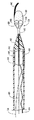
引き続き図37を参照すると、搬送装置900は、ガイド部材912の遠位方向に配置されたフィルタアセンブリ931を有する。本発明の教示に従い、搬送装置900は、拡張式アセンブリ940内を通りさらに任意選択でフィルタアセンブリ931内を通るよう配置されたガイドワイヤ932を有する。例示された構成で、ガイドワイヤ932は、その終端がフィルタセンブリ931になっており、このフィルタアセンブリ931は、以下により詳細に述べるように、ガイドワイヤ932の遠位端に結合されて非外傷性チップを含む。
With continued reference to FIG. 37, the delivery device 900 has a
フィルタアセンブリ931は、装置900の使用中に塞栓予防をもたらすように適合されている。図37および38に示されるように、フィルタアセンブリ931は、身体の管腔内への挿入が容易になるようにロープロファイルのものである。フィルタアセンブリ931と拡張式アセンブリ940との間には、移行部材936が配置されている。移行部材936は、ガイド部材912とフィルタアセンブリ931との移行をもたらすように適合されている。この移行部分があると、装置900が配置されている身体の管腔への損傷が予防され、また装置900が患者の体内の曲がりくねった構造を慎重に前進するときに、1つまたは複数の身体管腔の壁面または接合部に捕えられないようになる。図示するように、移行部材936は、その内部に配置されてガイドワイヤ932を受容するための通路938を含む。通路938は、その内部にガイドワイヤ932を確実に保持するように、または任意選択でガイドワイヤ932を取外し可能に受容するように適合させることができる。あるいは、移行部材936は、ガイドワイヤ932が通過しまたはガイドワイヤ932を受容する穴を含むことができる。さらに別の構成では、移行部材936が、ガイドワイヤ932の遠位端を受容するように適合された穴を含み、一方、移行部材936の遠位端は、フィルタアセンブリ931で形成されまたはフィルタアセンブリ931と協働する。
図37および38は、フィルタアセンブリ931の展開に備えて規制された状態のフィルタアセンブリ931を示し、一方、図39〜41は、展開しまたは作動させた状態のフィルタアセンブリ931を示す。図41に示すように、フィルタアセンブリ931は、フィルタバスケット934およびフィルタ933を含む。展開する前、フィルタ933は、フィルタバスケット934の内部に配置することができ、フィルタバスケット934の周りに配置することができ、またはこれらを組み合わせることができる。フィルタ933は、搬送装置900に関連した手順を実施している間に遊離する可能性のある、塞栓性の粒子または物質を捕捉するようになされており、あるいは任意選択で、ガイドワイヤ932および関連付けられたフィルタアセンブリ931から任意選択で搬送装置900を滑動可能に取り外すときのその他の手順を実施している間に遊離する可能性のある、塞栓性の粒子または物質を捕捉するようになされている。したがって任意選択でフィルタ933は、展開したときに、フィルタ933の遠位端が身体の管腔内に浮遊しかつフィルタ933の近位端がフィルタバスケット934に結合した状態で、身体の管腔内に浮遊することができる。別の構成で、フィルタ933の遠位端は、フィルタバスケット934の一部に結合することができる。
37 and 38 show the
フィルタ933は、織込みタイプまたは編込みタイプのプラスチックまたは金属のメッシュや、有孔ポリマーフィルム、Nitinolメッシュ、これらの組合せ、あるいは流動する血液中の物質を捕捉することができると同時に血液をその孔または開口部に通すことが可能なその他の材料などであって、これらに限定するものではない様々な異なる材料から製作することができる。一般にフィルタ933は、フィルタバスケット934内にフィルタ932を詰め込むことができる限り、かつ任意選択でフィルタが挿入される身体の管腔を通過する血流に浮遊する限り、かつ生体適合性である限り、様々な材料から製作することができる。
フィルタ933は、約50ミクロンから約200ミクロン、約60ミクロンから約180ミクロン、または約75ミクロンから約150ミクロンに及ぶ様々な種々のサイズの孔を有することができる。例えば孔は、円形や多角形、これらの組合せ、または本明細書に含まれる教示に照らして当業者に知られるその他の形状などであってこれらに限定されない様々な異なる形状を有することができる。したがってある構成では、フィルタ933は、種々のサイズおよび形状の孔を含むことができる。したがって、各孔の長軸または短軸は、約50ミクロンから約200ミクロン、約60ミクロンから約180ミクロン、または約75ミクロンから約150ミクロンに及ぶ、様々な異なるサイズを有することができる。一般に孔径は、フィルタを通過する血流がその孔によって損なわれないように、すなわち血液がフィルタを通過するのを妨げないように孔が寸法決めされ、かつより狭い下流の血管を閉塞させる可能性があり、組織への血流を阻止する可能性があり、または脳卒中や梗塞を引き起こす物質が収集されるように孔が寸法決めされる限り、必要に応じて様々に変えることができる。
上記の他、フィルタ933は、親水性被覆、ヘパリン添加被覆、ポリテトラフルオロエチレン(PTFE)被覆、シリコーン被覆、これらの組合せ、または本発明に含まれる教示に照らして当業者に知られまたは望まれる様々なその他の被覆で被覆することができる。
In addition to the above,
フィルタバスケット934は、フィルタ933が展開した後はフィルタ933を支持する。フィルタバスケット934は、本体962から延びる複数の支柱960を含む。フィルタバスケット934の支柱960は、外向きに広がってフィルタ933を身体の管腔内に位置決めするようになされている。支柱960の支柱960aは、非外傷性チップ948を含むことができ、支柱960aは、非外傷性チップ948の心線の少なくとも一部を形成した状態になっている。この支柱は、柔軟なコイル958で覆ってもよい。フィルタバスケット934の本体962は、ガイドワイヤ932を受容するように適合された穴967を含む。あるいは、本体962は、ガイドワイヤ932の遠位端を受容するようになされた通路を含むことができる。
The
フィルタ933は、様々な方法でフィルタバスケット934の支柱960に取着することができる。例えばフィルタ933は、接着剤、溶媒結合、熱結合、機械接続、またはこれらの組合せによって取着することができる。さらに、2つ以上の支柱960の遠位端は、ろ材932のストランドが通過し支柱960に取着することができる穴を含むことができる。あるいはストランドは、これを結び付け、フィルタ933で折り返し、フィルタ933に点着することができる。フィルタ933をフィルタバスケト934に結合しまたは接続する様々なその他の手法が存在する。
任意選択で、フィルタアセンブリ931は、フィルタアセンブリ931上の様々な位置に添着されたいくつかの放射線不透過性のバンドおよび/またはマーカーを含む。例えば、放射線を通さないバンドやマーカー、またはその他の手段を、フィルタ933、フィルタバスケット934、および/または支柱960に含めることができる。その他の構成で、搬送装置は一般に、その1つまたは複数の場所または位置で放射線不透過性であるための手段を含み、それによって、搬送装置および様々な要素およびそれらの構成要素の位置を見るのを助ける。
Optionally,
図示されるように、規制部材または機構925は支柱960を規制し、一方、点線で示す別の規制部材は、ガイド部材912の遠位端を規制する。任意選択で、規制部材または機構925は、ガイド部材912の遠位端と支柱960の両方を規制する。図37および38は支柱960を規制する規制部材または機構925を示すが、図39〜41は、規制部材または機構925から解放された支柱960を示す。図41の例示的な構成で、規制部材または機構925は、規制部材または機構525と同様の構成を有する。したがって規制部材または機構925は、いくつかのフープ、すなわちその1つまたは複数のフープが作動部材928を受容するようになされているいくつかのフープを形成し、任意選択で規制部材または機構925の一部であるコード929を含む。作動部材928は、コード929が支柱960に対して規制力を加えるように、フープ内に配置される。作動部材928は、フープから取り外すことができ、それによって支柱960を外向きに広げ、フィルタ933を展開することができる。コード929は、金属ワイヤ、ポリマー作動部材、あるいは作動部材または固定部材が通るフープが形成されるよう操作することができるその他の材料から作製することができる。任意選択でコード929は、1つまたは複数の支柱の影響下で、あるいはコード、フープ、および/または規制部材の構成および/または材料によってコード929に加えられまたは組み込まれた付勢力によって、外向きに広がるようになされている。
As shown, a restricting member or mechanism 925 restricts the
コード929は、様々な取着機構によって、フィルタアセンブリ931の1つまたは複数の支柱960に取着することができる。例えばコード929は、接着剤、機械式ファスナ、固定ループ、あるいはコード929を1つまたは複数の支柱960に確実に取着するその他の手法により、ガイド部材および/または支柱の1つまたは複数に取着することができる。あるいはコード929を作動部材928に取着し、作動部材928を近位方向に移動させたときに取り外すことができる。臨床医または内科医は、直接または作動機構または装置を使用することにより、作動部材928を長手方向に動かし始めることができる。規制部材または機構925の1つの特定の実施形態について述べたが、当業者なら、支柱960を規制するために本明細書で述べたその他の規制部材または機構を使用できることが理解されよう。
The
図示されるように、フィルタバスケット934は、規制部材または機構925の少なくとも一部を受容するように適合された1つまたは複数の穴970を含む。穴970は、フィルタアセンブリ931の様々な位置に配置することができる。限定を目的とするものではないが、例えば、本体962および各支柱960は1つまたは複数の穴970を含むことができる。規制部材または機構925は、コード929あるいは規制部材または機構925のその他の部分を任意選択で解放可能に支柱960の1つまたはフィルタバスケット934の本体962に結合した状態で、少なくとも部分的に、1つまたは複数の穴970を通して配置することができる。規制部材または機構925の作動部材928を近位方向に移動させることによって、支柱960は外向きに動き、フィルタ933を解放する。
As shown, the
規制部材または機構925の近位端(図示せず)または作動部材925は、臨床医または内科医がその規制部材または機構925を操作して規制力を支柱960に加えることができるように、触れることが可能である。任意選択で、規制部材または機構925の近位端は、この規制部材または機構925によって加えられた規制力を解除するため必要に応じて規制部材または機構925を動かすように操作することが可能な作動アセブリと、協働することができる。
A proximal end (not shown) or actuating member 925 of the restricting member or mechanism 925 touches so that a clinician or physician can manipulate the restricting member or mechanism 925 to apply a restricting force to the
図37〜41の例示的な構成で、規制部材または機構925の作動部材928は、コード929のフープとの係合解除するために、十分な運動および力で近位方向に移動させることができる。作動部材928とコード929との結合または係合を切断することによって、支柱960は外向きに広がりまたは移動してフィルタ933を展開させる。フィルタ933が展開した後、作動アセンブリ(図示せず)を操作し、本明細書で述べたものと同様の手法で図40に示すように、拡張式アセンブリ940およびステント942をガイド部材912から展開する。したがって2つの作動アセンブリ、すなわちその一方は規制部材または機構925を解放するものであり、他方は拡張式アセンブリ940およびステント942を解放するものである2つの作動アセンブリを使用することができる。
37-41, the actuating
規制部材または機構925は、フィルタバスケット934の支柱960を規制する1つの手段にすぎないことが理解されよう。その他の構成は、図2〜24に示す規制構成または規制手段などを使用することができるが、これらに限定されない。例えばフィルタバスケット934の支柱960は、本発明のガイド部材に関連した支柱と同様の手法で規制することができる。
It will be appreciated that the restricting member or mechanism 925 is just one means of restricting the
図40に戻ると、フィルタアセンブリ931を展開させかつ拡張式アセンブリ940およびステント942をガイド部材912から展開させた状態の、搬送装置900が示されている。拡張式アセンブリ940およびステント942の展開は、本明細書で論じたその他の拡張式アセンブリおよびステントに関して述べたものと同様の手法で実現することができる。同様に、支柱960を解放しかつフィルタ933が展開するように、規制部材または機構925を操作することによって、フィルタアセンブリ931を展開することができる。ガイドワイヤ932に対してガイド部材912を移動させることにより、またはその逆を行うことにより、またはこれらの組合せにより、拡張式アセンブリ940およびステント942をガイド部材912の内部から解放することができる。
Returning to FIG. 40, delivery device 900 is shown with
図42および43は、別の実施形態であるフィルタアセンブリ1031を示す。フィルタセンブリ1031は、別の実施形態である支柱1060を規制する手段を有する。この特定の支柱1060の構成は、支柱1060をガイドワイヤ932または移行部材936(図37)の遠位端に結合しまたは取着することができることを示している。支柱1060の長さは、ガイド部材1012の特定の構成に基づいて変えることができる。
42 and 43 show another embodiment, a
規制機構1064は、図43に示すように、支柱1060を規制位置に維持する。この実施形態で、規制機構1064は、各支柱1060に取着された管状部材1062と、内部に配置された規制または作動部材1025とを含む。各支柱1060に取着された管状部材1062について述べたが、1つまたは複数の管状部材1062を各支柱1060に取着でき、かつ/またはより少ない数の支柱1060それぞれが管状部材1062を含むことが理解されよう。
As shown in FIG. 43, the restricting
各管状部材1062は、規制または作動部材1025を受容するように適合される。図43に示すように、支柱1060が規制されると、管状部材1062は、規制または作動部材1025を受容するように1列に並ぶ。すなわち管状部材1062のそれぞれは、隣接する支柱1060上で他の管状部材1062と互い違いに配置され、その結果、管状部材1062は、フィルタアセンブリ1031の近位端から遠位端まで1列に並ぶようになる。次いで図43に示すように、一連の管状部材1062内を通るように規制または作動部材1025を配置して、支柱1060を規制し、この支柱が外向きに広がらないようにする。
Each
規制または作動機構1025は、フィルタアセンブリ1031からガイドワイヤ1032の管腔内まで延びて、ガイドワイヤ1012の近位端を終端とし、任意選択でガイド部材1012の近位端を越えて延びる。あるいは、規制または作動部材1025は、フィルタアセンブリ1031から近位方向に延びて、点線で示す開口部1069から出て行った後、ガイド部材1012の近位端を終端とし、さらに任意選択でガイド部材1012の近位端を越えて延びる。この後者の構成では、規制または作動部材1025がガイド部材1012の近位端に延びてさらに任意選択でガイド部材1012の近位端を越えて延びるので、規制または作動部材1025を、ガイド部材1012の外部にまたはガイド部材1012の外部に部分的に配置することができる。臨床医または内科医は、規制部材または機構1064を操作して、規制部材または機構1064によって加えられた規制力を解除できることが理解されよう。あるいは、規制部材または機構1064は、図6に関して述べた作動アセンブリなどであってこれらに限定するものではない本明細書で述べたものと同様の作動アセンブリによって、または当業者に知られる任意のその他の作動アセンブリによって、任意選択で操作することができる。
The restriction or
支柱1060に結合された各管状部材1062は、その材料がガイド部材1012を形成するものとおなじであっても異なるものであっても、金属、プラスチック、ポリマー、ポリマー、合成材料から製作することができる。一実施形態で、各管状部材1062はポリマーチューブであり、例えば接着剤でそれぞれの支柱1060に固定されたポリイミドまたはポリウレタンのチューブである。別の構成で、各管状部材1062は、接着剤またははんだでそれぞれの支柱1060に取着可能な金属カットチューブである。さらに別の構成で、各支柱1060は、支柱1060を規制して外向きに広がらないように作動部材1025が通過する開口部を含む。
Each
次に図44を参照すると、本発明の別の態様による別のフィルタアセンブリの例示的な構成が示されている。フィルタアセンブリ1131の機能の特徴は、本発明のその他のフィルタアセンブリに適用可能であることであり、またその逆も可能であることである。さらに、フィルタアセンブリ1131の1つまたは複数のその他の支柱に関する考察は、本発明の搬送装置のガイド部材に関連付けられた支柱にも適用可能である。
Referring now to FIG. 44, an exemplary configuration of another filter assembly according to another aspect of the present invention is shown. A functional feature of the
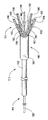
図44に示すように、フィルタアセンブリ1131は、本体1162と1つまたは複数の支柱1160を含む。1つまたは複数の支柱1160にはフィルタ1133が結合している。本体1162からは、フィルタ1133内を、関連するコイル1158を備えた非外傷性チップ1148が延びている。説明を簡単にするために、フィルタアセンブリ1131に関連付けられた規制部材または機構については図示しないが、本明細書で述べた規制部材または機構のいずれかを使用して、フィルタアセンブリ1131の1つまたは複数の支柱に規制力を加えることができることが理解されよう。
As shown in FIG. 44, the
支柱1160は、フィルタアセンブリ1131の本体1162から延びている。本明細書では、本体1162に一体的に形成された支柱1160について述べが、支柱1160は、本体1162に結合させた別個の部材でよいことが理解されよう。さらに、支柱1160は、ガイドワイヤ1132で一体的に形成することができ、またはガイドワイヤ1132に結合させた別個の部材でよい。
The
各支柱は、遠位部分1162、近位部分1166、さらに遠位部分1162と近位部分1166との間に配置された中間部分1164を含む。支柱1160は、フィルタ1133の外側または、フィルタ1133の内側で、フィルタ1133の縁部に沿って、フィルタ1133を通して、あるいは1または複数の処理の組合せにより、フィルタ1133に取着してよい。各支柱1160をフィルタ1133に接続するために表面積をさらに追加するには、遠位部分1162の断面寸法が中間部分1164よりも大きくなるように支柱1160を構成することができる。別の言い方をすれば、遠位部分1162の表面積は、中間部分1164の表面積よりも大きくすることができる。遠位部分1162の断面寸法によってもたらされた広い断面積によって、各支柱1160をフィルタ1133に結合する領域を広くすることができる。この構成では、各支柱1160とフィルタ1133との間に強力な結合が生成される。
Each strut includes a
同様に、各支柱1160は、近位部分1166の断面寸法が中間部分1164よりも大きくなるように、またそれと同時に任意選択で、近位部分1166の断面寸法が遠位部分1162と同様になるように、または大きくなるように、または小さくなるように構成することができる。断面寸法が大きいことによって、すなわち表面積が大きくなることによって、各支柱1160はさらに大きい付勢力を加えて支柱1160を外向きに広げ、フィルタ1133を展開することができる。
Similarly, each
遠位部分1162、中間部分1164、および/または近位部分1166の断面積を変化させることにより、遠位部分1162が血管の壁面に向かって動くように各支柱1160によって加えられた付勢の程度を変化させることができる。付勢力は、任意選択で各支柱1160の長さを変化させ、かつ/または各支柱1160の曲率を変化させることによって、変えることもできる。
The degree of bias applied by each
本明細書では、支柱1160のそれぞれが上述の構成を有する場合について述べたが、当業者なら、1つまたは複数の支柱1160を上述のように構成することができることを理解されよう。さらに各支柱1160は、同じ搬送装置のその他の支柱1160と比べて同様のまたは異なる付勢力を有することができるように、各支柱1160を任意選択で別々に構成することができる。付勢力を変化させることにより、この搬送装置を様々な異なる処置または血管構造に使用することができる。
Although the present description has described the case where each of the
支柱1160は、Nitinol、ステンレス鋼、金属、合金、複合材、プラスチック、ポリマー、合成材料、またはこれらの組合せから形成することができる。各支柱1160は、略直線状の遠位部分1162、近位部分1166、および/または中間部分1164を有することができる。あるいは各支柱1160は、略曲線状の遠位部分1162、近位部分1166、および/または中間部分1164を有することができる。さらに別の構成では、各支柱1160は、1つまたは複数の直線状部分および/または1つまたは複数の曲線状部分の組合せを有することができる。
The
管腔または穴1137の内部などの本体1162には、非外傷性チップ1148が結合されている。非外傷性チップ1148は、心線1156とその表面に配置された柔軟なコイル1158を含むことができる。心線156は、フィルタ1133の遠位端で開口部1170を通過する。あるいは心線1156は、フィルタ1133に形成された1つまたは複数の孔を通過する。フィルタ1133を非外傷性チップ1148に固定するため、固定コイル1186でコイル1158の一部とフィルタ1133の遠位端を取り囲む。これはフィルタ1133を非外傷性チップ1148に接続する1つの手法であるが、当業者なら、フィルタ1133を非外傷性チップ1148に接続する様々なその他の手法が明らかであろう。例えばフィルタ1133の遠位端は、接着剤、機械式ファスナ、クランプ留め、シール、摩擦嵌め、圧力嵌め、またはフィルタ1133を非外傷性チップ1148に接続するその他の手法を使用して、非外傷性チップ1148に結合することができる。別の構成では、フィルタ1133を非外傷性チップ1148に接続せず、非外傷性チップ1148の一部に沿って滑動させる。
次に図45および46を参照すると、フィルタアセンブリのフィルタを捕捉するのに使用可能な捕捉装置または機構の2つの例示的な実施形態が示されている。フィルタを展開した後は、ステント操作を行った後にフィルタを捕捉することが好ましい。より詳細には、フィルタで捕捉された塞栓性粒子を捕捉してこれを除去することが望ましい。 Referring now to FIGS. 45 and 46, two exemplary embodiments of a capture device or mechanism that can be used to capture the filter of the filter assembly are shown. After deploying the filter, it is preferable to capture the filter after performing a stent operation. More specifically, it is desirable to capture and remove the embolic particles captured by the filter.
図45は、本発明の一態様による捕捉装置1200を示す。捕捉装置1200は、捕捉カテーテル1202を含む。図示されるように、捕捉カテーテル1202は、捕捉部分1204と、捕捉部分1204に接続されまたは取着された位置決め部材1206とを含む。捕捉部分1204は、遠位端1208と近位端1210を有する。捕捉部分1204は、遠位端1208から延びてその近位端1210の開口部1214を終端とする管腔1212を含む。遠位端1208は、任意選択で1つまたは複数の放射線不透過マーカーまたはバンド1216を含み、その1つのみ図示している。同様に、位置決め部材1206の近位端は、1つまたは複数の放射線不透過マーカーまたはバンド1216を含むことができる。より一般的には、本発明の捕捉装置と搬送装置およびガイドワイヤのいずれかは、1つまたは複数の放射線不透過インジケータを含むことができ、そのようなインジケータは、マーカーやバンド、スタッドでもよく、またはその他の放射線不透過表示要素でもよい。
FIG. 45 illustrates a
管腔1212は、搬送装置のフィルタアセンブリ(図示せず)が取着されたガイドワイヤを受容するように構成される。一実施形態で、管腔1212は、点線で示されるストッパ部材1218であってその部材を貫通する穴1220を有する部材1218を含むことができる。参照符号1232が付された点線で示されるガイドワイヤは、ストッパ部材1218の穴1220を通過する。ガイドワイヤ1232は、本明細書で述べたものや当業者に知られるその他のものなど、これらに限定されない様々な構成を有することができる。
ストッパ部材1218は、塞栓性物質を逃がさないためフィルタアセンブリのフィルタが少なくとも閉じるように、ガイドワイヤ1232に結合されたフィルタアセンブリを捕捉カテーテル1202が管腔1212内で十分受容した後は、ガイドワイヤ1232の遠位端に配置されたフィルタアセンブリが穴1220を通過するのを防止する。ある構成では、フィルタアセンブリおよび結合されたフィルタが、捕捉装置1200の捕捉部分1204に完全に包封される。その他の構成では、フィルタアセンブリおよび/またはフィルタが、捕捉装置1200の捕捉部分1204によって部分的に包封される。当業者なら、ガイドワイヤ1232に結合されたフィルタアセンブリおよび/またはフィルタの捕捉がストッパによって完全にまたは部分的に促進されるものである限り、ストッパ部材1218の様々なその他の構成が明らかにされよう。
位置決め部材1206は、捕捉カテーテル1202に取着され、そしてガイドワイヤ1232に沿って捕捉カテーテル1202を移動させるのに使用することができるが、そのような動きは、カテーテル1202をガイドワイヤ1232に対して動かすことによって生じるものであっても、またはガイドワイヤ1232をカテーテル1202に対して動かすものであっても、またはこれらを組み合わせたものであってもよい。位置決め部材1206は、近位端1224に加えられた力が捕捉カテーテル1202の捕捉部分1204の長手方向の運動に変換されるよう、十分な剛性を有する。ある構成では、位置決め部材1206は中実部材であり、一方別の構成では、位置決め部材1206は部分的にまたは完全に中空である。位置決め部材1206は、ポリマー、プラスチック、ポリマー、合成材料、金属、合金、これらの組合せ、または医療装置に使用することが可能であり必要とされる剛性を有するその他の材料から製作することができる。
図46に示すように、捕捉装置1300の代替の実施形態が示されている。図示されるように、捕捉装置1300は管状部材に形をとり、そのような管状部材は、その長さに沿って完全に中空であっても部分的に中空であってもよい。捕捉装置1300は、遠位端1308に配置された捕捉部分1304を含む。管腔1312は、遠位端1308と、遠位端1308の近位の位置との間を延びて、開口部1326を終端とする。一実施形態で、開口部1326の位置と管腔1312の近位端とは一致し、したがって管腔1312は、捕捉装置1300の近位端1310から遠位端1308まで延びている。開口部1326は、図45の開口部1214と同様の手法でガイドワイヤ1332を受容するように適合されている。管腔1312は、搬送装置(図示せず)のフィルタアセンブリを受容するよう構成される。より詳細には、管腔1312は、ガイドワイヤ1322に結合されたフィルタアセンブリおよび/またはフィルタを完全にまたは部分的に受容する。
As shown in FIG. 46, an alternative embodiment of a
捕捉部分1304は、搬送装置のフィルタアセンブリが通過しないように構成される。この例示的な構成で、管腔1312の長さは、任意選択で捕捉部分1304がフィルタアセンブリおよび/またはそのフィルタ上を必要以上に進むことのないよう構成されている。その他の構成で、管腔1312は、これを捕捉するために必要とされる以上にフィルタアセンブリおよび/またはフィルタ上を進むことができる。別の構成では、管腔1312は、本明細書で論じたストッパ部材1218と同様のストッパ部材を含んでよい。さらに捕捉部分1304は、その遠位端および近位端に配置されかつ/またはその遠位端と近位端の間に配置されたマーカー1216と同様の、1つまたは複数の放射線不透過マーカーを任意選択で含むことができる。
The capture portion 1304 is configured so that the filter assembly of the transport device does not pass through. In this exemplary configuration, the length of
したがって一般に、本発明の実施形態は、ガイドワイヤ、ステント搬送装置、拡張式バルーン、塞栓予防装置、またはこれらのサブセット群の機能性を一緒にして身体の管腔内に挿入可能な単一装置に組み入れたシステム、方法、および装置を提供することができる。このように本発明の実施形態では、処置を施すのに必要な装置の数が減少し、処置を施すのに必要が時間が短縮し、処置の難しさおよび複雑さが低減し、それによってより安全な処置が可能になり、かつ患者に対する有効性が高まる。 Thus, in general, embodiments of the present invention provide a single device that can be inserted into a body lumen together with the functionality of a guidewire, stent delivery device, expandable balloon, embolic protection device, or subsets thereof. Integrated systems, methods, and devices can be provided. Thus, embodiments of the present invention reduce the number of devices required to perform a procedure, reduce the time required to perform a procedure, and reduce the difficulty and complexity of the procedure, thereby It enables safe treatment and increases the effectiveness for patients.
本発明の様々な搬送装置および関連付けられた拡張式アセンブリ、ステント、ガイド部材、アクチュエータアセンブリ、ガイドワイヤ、フィルタアセンブリ、およびその他の要素の部分は、互いに交換可能に使用することができる。したがって、ある搬送装置および関連付けられた構成部品および/または要素に関する記述は、本明細書に記載するその他の搬送装置および本明細書の開示に照らして当業者に知られるその他の装置にも適用可能である。 The various delivery devices and associated expandable assemblies, stents, guide members, actuator assemblies, guide wires, filter assemblies, and other element portions of the present invention can be used interchangeably. Accordingly, the statements regarding one transport device and associated components and / or elements are also applicable to other transport devices described herein and other devices known to those skilled in the art in light of the disclosure herein. It is.
本発明は、その趣旨または本質的な特徴から逸脱することなく、他の特定の形に具体化することができる。記載した実施形態は、全ての点において単なる例示と見なされ、限定を目的とするものではない。したがって本発明の範囲は、前述の事項ではなく添付の特許請求の範囲によって示される。請求の範囲およびその均等範囲に含まれる全ての変更は、本発明の範囲内に包含される。 The present invention may be embodied in other specific forms without departing from its spirit or essential characteristics. The described embodiments are to be considered in all respects only as illustrative and not restrictive. The scope of the invention is, therefore, indicated by the appended claims rather than by the foregoing. All changes that fall within the scope of the claims and their equivalents are embraced within the scope of the invention.
Claims (30)
前記拡張式アセンブリ上に配置されたステントと、
近位端および遠位端を有するガイド部材であって、前記ガイド部材の前記遠位端は1つまたは複数の支柱を具え且つ前記拡張式アセンブリを選択的に規制するようになされており、身体の管腔内に前記ガイド部材を配置することによって、同時に前記拡張式アセンブリおよび前記ステントが身体の管腔内に配置されるガイド部材と、
前記遠位端の表面と協働し、且つ前記拡張式アセンブリと前記ステントとを規制するように前記遠位端に規制力を加えるのを助ける規制部材と、
前記ガイド部材に沿って延び、前記規制部材を選択的に変位させるために前記規制部材に結合された、少なくとも1つの作動部材と
を含み、前記規制部材は、1つまたは複数の支柱を選択的に縫って進むコードであることを特徴とする身体の管腔内にステントを送出するように適合されたステント送出装置。An expandable assembly;
A stent disposed on the expandable assembly;
A guide member having a proximal end and a distal end, wherein the distal end of the guide member includes one or more struts and is configured to selectively regulate the expandable assembly; A guide member in which the expandable assembly and the stent are simultaneously placed in a body lumen by disposing the guide member in a lumen of the body;
A restricting member that cooperates with the surface of the distal end and assists in applying a restricting force to the distal end to restrict the expandable assembly and the stent;
The extending along the guide member, wherein coupled to the regulating member in order to selectively displace the regulating member, viewed contains at least one actuating member, the regulating member may select one or more struts A stent delivery device adapted to deliver a stent into a body lumen, characterized in that the cord is a sewn cord .
内側部分を含む拡張式バルーンと、
前記拡張式バルーンの前記内側部分と流体連絡する拡張式チューブと
をさらに含む請求項1に記載の装置。The expandable assembly is
An inflatable balloon including an inner portion;
The apparatus of claim 1, further comprising an expandable tube in fluid communication with the inner portion of the expandable balloon.
拡張式アセンブリと、
前記拡張式アセンブリ上に配置されたステントと、
近位端、遠位端、およびガイド部材の前記近位端から前記遠位端まで延びる管腔を有するガイド部材であって、前記ガイド部材の前記遠位端が、1つまたは複数の支柱を具えると共に、前記遠位端の表面と協働するように適合され且つ前記拡張式アセンブリと前記ステントとを規制するために前記遠位端を選択的に規制するのを助ける規制部材と協働して、前記拡張式アセンブリを選択的に規制するよう構成されたガイド部材と、
前記ガイド部材の前記長さに沿って延びるガイドワイヤであって、前記ガイド部材の前記管腔内に少なくとも部分的に配置されたガイドワイヤと、
前記規制部材であって、規制位置と解放位置の間に前記1つまたは複数の支柱を選択的に位置決めするよう構成された規制部材と、
前記ガイド部材に沿って延び、前記規制部材を選択的に変位させるために前記規制部材に結合された少なくとも1つの作動部材と
を具え、
前記ガイド部材を前記身体の管腔内に配置することによって、同時に、前記拡張式アセンブリと前記ステントとが前記身体の管腔内に配置され、
前記規制部材は、前記1つまたは複数の支柱に選択的に固定されたコードであることを特徴とする装置。A stent delivery device configured to deliver a stent to a body lumen comprising:
An expandable assembly;
A stent disposed on the expandable assembly;
A guide member having a proximal end, a distal end, and a lumen extending from the proximal end to the distal end of the guide member, wherein the distal end of the guide member includes one or more struts. And cooperating with a restricting member adapted to cooperate with the surface of the distal end and to selectively restrict the distal end to restrict the expandable assembly and the stent. A guide member configured to selectively restrict the expandable assembly;
A guide wire extending along the length of the guide member, wherein the guide wire is at least partially disposed within the lumen of the guide member;
A restriction member configured to selectively position the one or more struts between a restriction position and a release position;
At least one actuating member extending along the guide member and coupled to the restricting member to selectively displace the restricting member;
By placing the guide member within the body lumen, at the same time, the expandable assembly and the stent are disposed within the body lumen ;
The apparatus is characterized in that the restricting member is a cord selectively fixed to the one or more support columns .
内側部分を有する拡張式バルーンと、
前記拡張式バルーンの前記内側部分に流体連絡する拡張式チューブと
を含むことを特徴とする請求項14に記載の装置。The expandable assembly comprises:
An inflatable balloon having an inner portion;
The device of claim 14 , comprising an expandable tube in fluid communication with the inner portion of the expandable balloon.
Applications Claiming Priority (6)
| Application Number | Priority Date | Filing Date | Title |
|---|---|---|---|
| US34466101P | 2001-11-09 | 2001-11-09 | |
| US34533301P | 2001-11-09 | 2001-11-09 | |
| US34109201P | 2001-12-12 | 2001-12-12 | |
| US34750002P | 2002-01-11 | 2002-01-11 | |
| US10/290,099 US7594926B2 (en) | 2001-11-09 | 2002-11-07 | Methods, systems and devices for delivering stents |
| PCT/US2002/035942 WO2003041610A2 (en) | 2001-11-09 | 2002-11-08 | Stent delivery device |
Publications (3)
| Publication Number | Publication Date |
|---|---|
| JP2005508699A JP2005508699A (en) | 2005-04-07 |
| JP2005508699A5 JP2005508699A5 (en) | 2006-01-05 |
| JP4540987B2 true JP4540987B2 (en) | 2010-09-08 |
Family
ID=27540739
Family Applications (2)
| Application Number | Title | Priority Date | Filing Date |
|---|---|---|---|
| JP2003543497A Expired - Fee Related JP4540987B2 (en) | 2001-11-09 | 2002-11-08 | Stent delivery device |
| JP2003541443A Expired - Fee Related JP4350514B2 (en) | 2001-11-09 | 2002-11-08 | Stent delivery device |
Family Applications After (1)
| Application Number | Title | Priority Date | Filing Date |
|---|---|---|---|
| JP2003541443A Expired - Fee Related JP4350514B2 (en) | 2001-11-09 | 2002-11-08 | Stent delivery device |
Country Status (8)
| Country | Link |
|---|---|
| US (1) | US7594926B2 (en) |
| EP (3) | EP1441795B1 (en) |
| JP (2) | JP4540987B2 (en) |
| AT (3) | ATE415898T1 (en) |
| CA (2) | CA2466051C (en) |
| DE (2) | DE60226162T2 (en) |
| ES (2) | ES2301711T3 (en) |
| WO (2) | WO2003039345A2 (en) |
Families Citing this family (152)
| Publication number | Priority date | Publication date | Assignee | Title |
|---|---|---|---|---|
| US6855123B2 (en) | 2002-08-02 | 2005-02-15 | Flow Cardia, Inc. | Therapeutic ultrasound system |
| AU6299401A (en) * | 2000-05-08 | 2001-11-20 | Qtl Biosystems Llc | Improvements to the fluorescent polymer-qtl approach to biosensing |
| EP1441666B1 (en) | 2001-11-09 | 2008-01-23 | Rubicon Medical, Inc. | Stent delivery device with embolic protection |
| US6989024B2 (en) | 2002-02-28 | 2006-01-24 | Counter Clockwise, Inc. | Guidewire loaded stent for delivery through a catheter |
| IL149828A (en) * | 2002-05-23 | 2007-09-20 | Ronnie Levi | Medical device having a tubular portion |
| US7695446B2 (en) | 2002-12-02 | 2010-04-13 | Gi Dynamics, Inc. | Methods of treatment using a bariatric sleeve |
| US7608114B2 (en) | 2002-12-02 | 2009-10-27 | Gi Dynamics, Inc. | Bariatric sleeve |
| EP1569582B1 (en) | 2002-12-02 | 2017-05-31 | GI Dynamics, Inc. | Bariatric sleeve |
| US7678068B2 (en) | 2002-12-02 | 2010-03-16 | Gi Dynamics, Inc. | Atraumatic delivery devices |
| US7025791B2 (en) | 2002-12-02 | 2006-04-11 | Gi Dynamics, Inc. | Bariatric sleeve |
| US7300460B2 (en) | 2002-12-31 | 2007-11-27 | Counter Clockwise, Inc. | Bifurcated guidewire and methods of use |
| US20040193178A1 (en) | 2003-03-26 | 2004-09-30 | Cardiomind, Inc. | Multiple joint implant delivery systems for sequentially-controlled implant deployment |
| AU2004226464A1 (en) | 2003-03-26 | 2004-10-14 | Cardiomind, Inc. | Implant delivery technologies |
| US7771463B2 (en) | 2003-03-26 | 2010-08-10 | Ton Dai T | Twist-down implant delivery technologies |
| US7947070B2 (en) * | 2003-05-16 | 2011-05-24 | Boston Scientific Scimed, Inc. | Dilatation and stent delivery system and related methods |
| US20050075625A1 (en) * | 2003-07-18 | 2005-04-07 | Kinh-Luan Dao | Medical devices |
| CA2542368A1 (en) * | 2003-10-15 | 2005-04-28 | Kabushikikaisha Igaki Iryo Sekkei | Device for delivery of stent for vessel |
| IL158960A0 (en) * | 2003-11-19 | 2004-05-12 | Neovasc Medical Ltd | Vascular implant |
| US8057420B2 (en) | 2003-12-09 | 2011-11-15 | Gi Dynamics, Inc. | Gastrointestinal implant with drawstring |
| EP1708655A1 (en) | 2003-12-09 | 2006-10-11 | GI Dynamics, Inc. | Apparatus to be anchored within the gastrointestinal tract and anchoring method |
| US9254213B2 (en) * | 2004-01-09 | 2016-02-09 | Rubicon Medical, Inc. | Stent delivery device |
| US7651521B2 (en) * | 2004-03-02 | 2010-01-26 | Cardiomind, Inc. | Corewire actuated delivery system with fixed distal stent-carrying extension |
| US7232462B2 (en) * | 2004-03-31 | 2007-06-19 | Cook Incorporated | Self centering delivery catheter |
| GB2427362B (en) * | 2004-04-19 | 2008-09-24 | Etview Ltd | Imaging catheter |
| US7837643B2 (en) | 2004-07-09 | 2010-11-23 | Gi Dynamics, Inc. | Methods and devices for placing a gastrointestinal sleeve |
| AU2005287010B2 (en) | 2004-09-17 | 2010-04-15 | Gi Dynamics, Inc. | Gastrointestinal anchor |
| ATE501687T1 (en) * | 2004-09-28 | 2011-04-15 | Cordis Corp | MEDICAL THIN FILM DEVICE AND DELIVERY SYSTEM |
| US8221343B2 (en) | 2005-01-20 | 2012-07-17 | Flowcardia, Inc. | Vibrational catheter devices and methods for making same |
| WO2006099311A1 (en) * | 2005-03-14 | 2006-09-21 | The Cleveland Clinic Foundation | Balloon catheter for use with expandable stents |
| US8043323B2 (en) * | 2006-10-18 | 2011-10-25 | Inspiremd Ltd. | In vivo filter assembly |
| US7976488B2 (en) | 2005-06-08 | 2011-07-12 | Gi Dynamics, Inc. | Gastrointestinal anchor compliance |
| US7780723B2 (en) | 2005-06-13 | 2010-08-24 | Edwards Lifesciences Corporation | Heart valve delivery system |
| US8968379B2 (en) * | 2005-09-02 | 2015-03-03 | Medtronic Vascular, Inc. | Stent delivery system with multiple evenly spaced pullwires |
| JP4834367B2 (en) * | 2005-09-29 | 2011-12-14 | 日本ライフライン株式会社 | Guide wire and manufacturing method thereof |
| US20070100414A1 (en) | 2005-11-02 | 2007-05-03 | Cardiomind, Inc. | Indirect-release electrolytic implant delivery systems |
| US8051797B1 (en) * | 2005-11-07 | 2011-11-08 | Boston Scientific Scimed, Inc. | Device to stabilize and align a pre-mounted stent |
| US8961532B2 (en) * | 2006-01-06 | 2015-02-24 | Bayer Essure Inc. | Atraumatic catheter tip |
| US20080172120A1 (en) * | 2007-01-12 | 2008-07-17 | Calvin Fenn | Endoprosthesis delivery systems and related methods |
| US8801647B2 (en) | 2007-02-22 | 2014-08-12 | Gi Dynamics, Inc. | Use of a gastrointestinal sleeve to treat bariatric surgery fistulas and leaks |
| US20080255654A1 (en) * | 2007-03-22 | 2008-10-16 | Bay Street Medical | System for delivering a stent |
| US8088154B2 (en) * | 2007-03-31 | 2012-01-03 | Cook Medical Technologies Llc | Medical device delivery system with sheath separation |
| US9144508B2 (en) | 2007-07-19 | 2015-09-29 | Back Bay Medical Inc. | Radially expandable stent |
| US8252035B2 (en) * | 2007-08-01 | 2012-08-28 | Cappella, Inc. | Device delivery system with two stage withdrawal |
| DE102007040868A1 (en) * | 2007-08-29 | 2009-04-16 | Innora Gmbh | Balloon catheter with protection against unfolding |
| WO2009061882A1 (en) * | 2007-11-07 | 2009-05-14 | Cook Incorporated | Method and apparatus for introducing expandable intraluminal prosthesis |
| US10517617B2 (en) | 2007-12-20 | 2019-12-31 | Angiodynamics, Inc. | Systems and methods for removing undesirable material within a circulatory system utilizing a balloon catheter |
| US11589880B2 (en) | 2007-12-20 | 2023-02-28 | Angiodynamics, Inc. | System and methods for removing undesirable material within a circulatory system utilizing during a surgical procedure |
| US8313525B2 (en) | 2008-03-18 | 2012-11-20 | Medtronic Ventor Technologies, Ltd. | Valve suturing and implantation procedures |
| EP2273948A4 (en) * | 2008-04-03 | 2014-01-01 | Gardia Medical Ltd | Delivery catheter with constraining sheath and methods of deploying medical devices into a body lumen |
| US9061119B2 (en) | 2008-05-09 | 2015-06-23 | Edwards Lifesciences Corporation | Low profile delivery system for transcatheter heart valve |
| US9402707B2 (en) | 2008-07-22 | 2016-08-02 | Neuravi Limited | Clot capture systems and associated methods |
| US8777976B2 (en) | 2008-07-22 | 2014-07-15 | Neuravi Limited | Clot capture systems and associated methods |
| US8652202B2 (en) | 2008-08-22 | 2014-02-18 | Edwards Lifesciences Corporation | Prosthetic heart valve and delivery apparatus |
| GB0822110D0 (en) * | 2008-12-03 | 2009-01-07 | Angiomed Ag | Catheter sheath for implant delivery |
| US8858610B2 (en) | 2009-01-19 | 2014-10-14 | W. L. Gore & Associates, Inc. | Forced deployment sequence |
| US8657870B2 (en) | 2009-06-26 | 2014-02-25 | Biosensors International Group, Ltd. | Implant delivery apparatus and methods with electrolytic release |
| WO2011031972A1 (en) * | 2009-09-10 | 2011-03-17 | Novostent Corporation | Vascular prosthesis delivery system and method |
| US8475513B2 (en) | 2009-12-02 | 2013-07-02 | Nedunchezian Sithian | Stent graft apparatus and method |
| US8628554B2 (en) | 2010-06-13 | 2014-01-14 | Virender K. Sharma | Intragastric device for treating obesity |
| US9526648B2 (en) | 2010-06-13 | 2016-12-27 | Synerz Medical, Inc. | Intragastric device for treating obesity |
| US10420665B2 (en) | 2010-06-13 | 2019-09-24 | W. L. Gore & Associates, Inc. | Intragastric device for treating obesity |
| US10010439B2 (en) | 2010-06-13 | 2018-07-03 | Synerz Medical, Inc. | Intragastric device for treating obesity |
| US20120065644A1 (en) * | 2010-09-15 | 2012-03-15 | Abbott Cardiovascular Systems, Inc. | Stent deployment system with retractable shealth |
| EP2629684B1 (en) | 2010-10-22 | 2018-07-25 | Neuravi Limited | Clot engagement and removal system |
| US9387104B2 (en) * | 2010-12-30 | 2016-07-12 | Boston Scientific Scimed, Inc. | Loading basket for a stent delivery system |
| US20120172887A1 (en) | 2011-01-05 | 2012-07-05 | Wilson-Cook Medical, Inc. d/b/a Cook Endoscopy | Proximal Release Expandable Prosthesis Delivery System |
| US9155619B2 (en) | 2011-02-25 | 2015-10-13 | Edwards Lifesciences Corporation | Prosthetic heart valve delivery apparatus |
| WO2012120490A2 (en) | 2011-03-09 | 2012-09-13 | Neuravi Limited | A clot retrieval device for removing occlusive clot from a blood vessel |
| US11259824B2 (en) | 2011-03-09 | 2022-03-01 | Neuravi Limited | Clot retrieval device for removing occlusive clot from a blood vessel |
| WO2014139845A1 (en) | 2013-03-14 | 2014-09-18 | Neuravi Limited | A clot retrieval device for removing occlusive clot from a blood vessel |
| US9744033B2 (en) | 2011-04-01 | 2017-08-29 | W.L. Gore & Associates, Inc. | Elastomeric leaflet for prosthetic heart valves |
| US8696731B2 (en) | 2011-06-10 | 2014-04-15 | DePuy Synthes Products, LLC | Lock/floating marker band on pusher wire for self-expanding stents or medical devices |
| US10117765B2 (en) | 2011-06-14 | 2018-11-06 | W.L. Gore Associates, Inc | Apposition fiber for use in endoluminal deployment of expandable implants |
| US9339384B2 (en) | 2011-07-27 | 2016-05-17 | Edwards Lifesciences Corporation | Delivery systems for prosthetic heart valve |
| US9554806B2 (en) | 2011-09-16 | 2017-01-31 | W. L. Gore & Associates, Inc. | Occlusive devices |
| US9782282B2 (en) | 2011-11-14 | 2017-10-10 | W. L. Gore & Associates, Inc. | External steerable fiber for use in endoluminal deployment of expandable devices |
| US9877858B2 (en) * | 2011-11-14 | 2018-01-30 | W. L. Gore & Associates, Inc. | External steerable fiber for use in endoluminal deployment of expandable devices |
| US20130144328A1 (en) * | 2011-12-06 | 2013-06-06 | Boston Scientific Scimed, Inc. | Expanding distal sheath with combined embolic protection |
| US9375308B2 (en) | 2012-03-13 | 2016-06-28 | W. L. Gore & Associates, Inc. | External steerable fiber for use in endoluminal deployment of expandable devices |
| JP2014090969A (en) * | 2012-11-06 | 2014-05-19 | Kyoto Medical Planning Ltd | Stent feeder |
| US9642635B2 (en) | 2013-03-13 | 2017-05-09 | Neuravi Limited | Clot removal device |
| US9433429B2 (en) | 2013-03-14 | 2016-09-06 | Neuravi Limited | Clot retrieval devices |
| ES2713633T3 (en) | 2013-03-14 | 2019-05-23 | Neuravi Ltd | Devices and methods for elimination of severe blockages of blood vessels |
| US11911258B2 (en) | 2013-06-26 | 2024-02-27 | W. L. Gore & Associates, Inc. | Space filling devices |
| US10285720B2 (en) | 2014-03-11 | 2019-05-14 | Neuravi Limited | Clot retrieval system for removing occlusive clot from a blood vessel |
| US9364361B2 (en) * | 2014-03-13 | 2016-06-14 | Abbott Cardiovascular Systems Inc. | Striped sheaths for medical devices |
| US20170119410A1 (en) * | 2014-04-29 | 2017-05-04 | Board Of Regents Of The University Of Nebraska | Surgical Snare Device |
| US10792056B2 (en) | 2014-06-13 | 2020-10-06 | Neuravi Limited | Devices and methods for removal of acute blockages from blood vessels |
| US10441301B2 (en) | 2014-06-13 | 2019-10-15 | Neuravi Limited | Devices and methods for removal of acute blockages from blood vessels |
| US10265086B2 (en) | 2014-06-30 | 2019-04-23 | Neuravi Limited | System for removing a clot from a blood vessel |
| US10363054B2 (en) | 2014-11-26 | 2019-07-30 | Neuravi Limited | Clot retrieval device for removing occlusive clot from a blood vessel |
| US11253278B2 (en) | 2014-11-26 | 2022-02-22 | Neuravi Limited | Clot retrieval system for removing occlusive clot from a blood vessel |
| US10617435B2 (en) | 2014-11-26 | 2020-04-14 | Neuravi Limited | Clot retrieval device for removing clot from a blood vessel |
| JP2018515246A (en) | 2015-05-14 | 2018-06-14 | ダブリュ.エル.ゴア アンド アソシエイツ,インコーポレイティドW.L. Gore & Associates, Incorporated | Devices and methods for atrial appendage occlusion |
| US10179046B2 (en) | 2015-08-14 | 2019-01-15 | Edwards Lifesciences Corporation | Gripping and pushing device for medical instrument |
| US11259920B2 (en) | 2015-11-03 | 2022-03-01 | Edwards Lifesciences Corporation | Adapter for prosthesis delivery device and methods of use |
| US10321996B2 (en) | 2015-11-11 | 2019-06-18 | Edwards Lifesciences Corporation | Prosthetic valve delivery apparatus having clutch mechanism |
| US10799677B2 (en) | 2016-03-21 | 2020-10-13 | Edwards Lifesciences Corporation | Multi-direction steerable handles for steering catheters |
| US11219746B2 (en) | 2016-03-21 | 2022-01-11 | Edwards Lifesciences Corporation | Multi-direction steerable handles for steering catheters |
| US10799676B2 (en) | 2016-03-21 | 2020-10-13 | Edwards Lifesciences Corporation | Multi-direction steerable handles for steering catheters |
| US10779980B2 (en) | 2016-04-27 | 2020-09-22 | Synerz Medical, Inc. | Intragastric device for treating obesity |
| EP3782562A1 (en) | 2016-08-17 | 2021-02-24 | Neuravi Limited | A clot retrieval system for removing occlusive clot from a blood vessel |
| JP7046924B2 (en) | 2016-09-06 | 2022-04-04 | ニューラヴィ・リミテッド | Clot recovery device for removing obstructive clots from blood vessels |
| US11744692B2 (en) | 2017-02-23 | 2023-09-05 | Boston Scientific Scimed, Inc. | Medical drain device |
| US11224511B2 (en) | 2017-04-18 | 2022-01-18 | Edwards Lifesciences Corporation | Heart valve sealing devices and delivery devices therefor |
| ES2906555T3 (en) | 2017-04-18 | 2022-04-19 | Edwards Lifesciences Corp | Heart valve sealing devices and delivery devices therefor |
| US10973634B2 (en) | 2017-04-26 | 2021-04-13 | Edwards Lifesciences Corporation | Delivery apparatus for a prosthetic heart valve |
| JP6949546B2 (en) * | 2017-04-28 | 2021-10-13 | 川澄化学工業株式会社 | Transport catheter and intravascular indwelling device transport device |
| US10959846B2 (en) | 2017-05-10 | 2021-03-30 | Edwards Lifesciences Corporation | Mitral valve spacer device |
| JP2020526274A (en) | 2017-06-30 | 2020-08-31 | エドワーズ ライフサイエンシーズ コーポレイションEdwards Lifesciences Corporation | Locking and releasing mechanism for transcatheter implantable devices |
| CR20190571A (en) | 2017-06-30 | 2020-04-19 | Edwards Lifesciences Corp | Docking stations transcatheter valves |
| US10857334B2 (en) | 2017-07-12 | 2020-12-08 | Edwards Lifesciences Corporation | Reduced operation force inflator |
| US10806573B2 (en) | 2017-08-22 | 2020-10-20 | Edwards Lifesciences Corporation | Gear drive mechanism for heart valve delivery apparatus |
| US11051939B2 (en) | 2017-08-31 | 2021-07-06 | Edwards Lifesciences Corporation | Active introducer sheath system |
| US11173023B2 (en) | 2017-10-16 | 2021-11-16 | W. L. Gore & Associates, Inc. | Medical devices and anchors therefor |
| JP7237955B2 (en) | 2017-10-18 | 2023-03-13 | エドワーズ ライフサイエンシーズ コーポレイション | catheter assembly |
| US11207499B2 (en) | 2017-10-20 | 2021-12-28 | Edwards Lifesciences Corporation | Steerable catheter |
| US10857015B2 (en) * | 2018-03-21 | 2020-12-08 | Medtronic Vascular, Inc. | Variable speed retraction mechanism delivery system and method |
| CN111971001B (en) * | 2018-04-09 | 2023-09-12 | 波士顿科学国际有限公司 | Stent delivery system with reduced deployment force |
| US11844914B2 (en) | 2018-06-05 | 2023-12-19 | Edwards Lifesciences Corporation | Removable volume indicator for syringe |
| US10842498B2 (en) | 2018-09-13 | 2020-11-24 | Neuravi Limited | Systems and methods of restoring perfusion to a vessel |
| US11406416B2 (en) | 2018-10-02 | 2022-08-09 | Neuravi Limited | Joint assembly for vasculature obstruction capture device |
| US11779728B2 (en) | 2018-11-01 | 2023-10-10 | Edwards Lifesciences Corporation | Introducer sheath with expandable introducer |
| ES2910600T3 (en) | 2019-03-04 | 2022-05-12 | Neuravi Ltd | Powered Clot Recovery Catheter |
| US10821267B1 (en) | 2019-08-14 | 2020-11-03 | Vasoinnovations Inc. | Apparatus and method for advancing catheters or other medical devices through a lumen |
| US10773059B1 (en) | 2019-08-14 | 2020-09-15 | Vasoinnovations, Inc. | Apparatus and method for advancing catheters or other medical devices through a lumen |
| US20210220626A1 (en) | 2019-08-14 | 2021-07-22 | Vasoinnovations, Inc. | Apparatus and method for advancing catheters or other medical devices through a lumen |
| US10792469B1 (en) | 2019-08-14 | 2020-10-06 | Vasoinnovations Inc. | Devices, systems, and methods for delivering catheters or other medical devices to locations within a patients body |
| US10828470B1 (en) | 2019-08-14 | 2020-11-10 | Vasoinnovations Inc. | Apparatus and method for advancing catheters or other medical devices through a lumen |
| US11529495B2 (en) | 2019-09-11 | 2022-12-20 | Neuravi Limited | Expandable mouth catheter |
| US11712231B2 (en) | 2019-10-29 | 2023-08-01 | Neuravi Limited | Proximal locking assembly design for dual stent mechanical thrombectomy device |
| US11779364B2 (en) | 2019-11-27 | 2023-10-10 | Neuravi Limited | Actuated expandable mouth thrombectomy catheter |
| US11839725B2 (en) | 2019-11-27 | 2023-12-12 | Neuravi Limited | Clot retrieval device with outer sheath and inner catheter |
| US11517340B2 (en) | 2019-12-03 | 2022-12-06 | Neuravi Limited | Stentriever devices for removing an occlusive clot from a vessel and methods thereof |
| US11648020B2 (en) | 2020-02-07 | 2023-05-16 | Angiodynamics, Inc. | Device and method for manual aspiration and removal of an undesirable material |
| US11944327B2 (en) | 2020-03-05 | 2024-04-02 | Neuravi Limited | Expandable mouth aspirating clot retrieval catheter |
| US11633198B2 (en) | 2020-03-05 | 2023-04-25 | Neuravi Limited | Catheter proximal joint |
| US11883043B2 (en) | 2020-03-31 | 2024-01-30 | DePuy Synthes Products, Inc. | Catheter funnel extension |
| US11759217B2 (en) | 2020-04-07 | 2023-09-19 | Neuravi Limited | Catheter tubular support |
| US11730501B2 (en) | 2020-04-17 | 2023-08-22 | Neuravi Limited | Floating clot retrieval device for removing clots from a blood vessel |
| US11871946B2 (en) | 2020-04-17 | 2024-01-16 | Neuravi Limited | Clot retrieval device for removing clot from a blood vessel |
| US11717308B2 (en) | 2020-04-17 | 2023-08-08 | Neuravi Limited | Clot retrieval device for removing heterogeneous clots from a blood vessel |
| US11737771B2 (en) | 2020-06-18 | 2023-08-29 | Neuravi Limited | Dual channel thrombectomy device |
| US11937836B2 (en) | 2020-06-22 | 2024-03-26 | Neuravi Limited | Clot retrieval system with expandable clot engaging framework |
| US11395669B2 (en) | 2020-06-23 | 2022-07-26 | Neuravi Limited | Clot retrieval device with flexible collapsible frame |
| US11439418B2 (en) | 2020-06-23 | 2022-09-13 | Neuravi Limited | Clot retrieval device for removing clot from a blood vessel |
| TW202214198A (en) | 2020-08-24 | 2022-04-16 | 美商愛德華生命科學公司 | Methods and systems for aligning a commissure of a prosthetic heart valve with a commissure of a native valve |
| JP2023540067A (en) | 2020-08-31 | 2023-09-21 | エドワーズ ライフサイエンシーズ コーポレイション | Systems and methods for crimping and device preparation |
| US11864781B2 (en) | 2020-09-23 | 2024-01-09 | Neuravi Limited | Rotating frame thrombectomy device |
| US11937837B2 (en) | 2020-12-29 | 2024-03-26 | Neuravi Limited | Fibrin rich / soft clot mechanical thrombectomy device |
| US11872354B2 (en) | 2021-02-24 | 2024-01-16 | Neuravi Limited | Flexible catheter shaft frame with seam |
| US11937839B2 (en) | 2021-09-28 | 2024-03-26 | Neuravi Limited | Catheter with electrically actuated expandable mouth |
Family Cites Families (152)
| Publication number | Priority date | Publication date | Assignee | Title |
|---|---|---|---|---|
| US3472230A (en) | 1966-12-19 | 1969-10-14 | Fogarty T J | Umbrella catheter |
| US3592186A (en) | 1969-01-28 | 1971-07-13 | Claude Oster | Cytologic scraper |
| US3683904A (en) | 1970-10-05 | 1972-08-15 | Howard B Forster | Pessaries |
| US3889657A (en) | 1974-02-12 | 1975-06-17 | Gomco Surgical Mfg Co | Uterine aspirating curette |
| US3952747A (en) | 1974-03-28 | 1976-04-27 | Kimmell Jr Garman O | Filter and filter insertion instrument |
| US3996938A (en) | 1975-07-10 | 1976-12-14 | Clark Iii William T | Expanding mesh catheter |
| US4046150A (en) | 1975-07-17 | 1977-09-06 | American Hospital Supply Corporation | Medical instrument for locating and removing occlusive objects |
| CH616337A5 (en) | 1977-10-21 | 1980-03-31 | Schneider Medintag Ag | |
| US4271839A (en) | 1979-07-25 | 1981-06-09 | Thomas J. Fogarty | Dilation catheter method and apparatus |
| US4307722A (en) | 1979-08-14 | 1981-12-29 | Evans Joseph M | Dilators for arterial dilation |
| US4413989A (en) | 1980-09-08 | 1983-11-08 | Angiomedics Corporation | Expandable occlusion apparatus |
| US4367747A (en) | 1980-10-01 | 1983-01-11 | Lothar Witzel | Pneumatic dilatator for introdution into the esophagus |
| US4425908A (en) | 1981-10-22 | 1984-01-17 | Beth Israel Hospital | Blood clot filter |
| US4447227A (en) | 1982-06-09 | 1984-05-08 | Endoscopy Surgical Systems, Inc. | Multi-purpose medical devices |
| US4643184A (en) | 1982-09-29 | 1987-02-17 | Mobin Uddin Kazi | Embolus trap |
| US4540404A (en) | 1983-01-19 | 1985-09-10 | Datascope Corp. | Balloon catheter with intrinsic introducer for percutaneous insertion into a blood vessel over a guide wire, and method of use |
| US5190546A (en) | 1983-10-14 | 1993-03-02 | Raychem Corporation | Medical devices incorporating SIM alloy elements |
| US5104399A (en) * | 1986-12-10 | 1992-04-14 | Endovascular Technologies, Inc. | Artificial graft and implantation method |
| US4631052A (en) | 1984-01-03 | 1986-12-23 | Intravascular Surgical Instruments, Inc. | Method and apparatus for surgically removing remote deposits |
| US4590938A (en) | 1984-05-04 | 1986-05-27 | Segura Joseph W | Medical retriever device |
| US4957482A (en) | 1988-12-19 | 1990-09-18 | Surgical Systems & Instruments, Inc. | Atherectomy device with a positive pump means |
| US5135531A (en) | 1984-05-14 | 1992-08-04 | Surgical Systems & Instruments, Inc. | Guided atherectomy system |
| US5007896A (en) | 1988-12-19 | 1991-04-16 | Surgical Systems & Instruments, Inc. | Rotary-catheter for atherectomy |
| US4842579B1 (en) | 1984-05-14 | 1995-10-31 | Surgical Systems & Instr Inc | Atherectomy device |
| DK151404C (en) | 1984-05-23 | 1988-07-18 | Cook Europ Aps William | FULLY FILTER FOR IMPLANTATION IN A PATIENT'S BLOOD |
| US4926858A (en) | 1984-05-30 | 1990-05-22 | Devices For Vascular Intervention, Inc. | Atherectomy device for severe occlusions |
| US4979951A (en) | 1984-05-30 | 1990-12-25 | Simpson John B | Atherectomy device and method |
| US4580568A (en) | 1984-10-01 | 1986-04-08 | Cook, Incorporated | Percutaneous endovascular stent and method for insertion thereof |
| US5232445A (en) | 1984-11-23 | 1993-08-03 | Tassilo Bonzel | Dilatation catheter |
| DE3442736A1 (en) | 1984-11-23 | 1986-06-05 | Tassilo Dr.med. 7800 Freiburg Bonzel | DILATATION CATHETER |
| US4790813A (en) | 1984-12-17 | 1988-12-13 | Intravascular Surgical Instruments, Inc. | Method and apparatus for surgically removing remote deposits |
| US4807626A (en) | 1985-02-14 | 1989-02-28 | Mcgirr Douglas B | Stone extractor and method |
| US4706671A (en) | 1985-05-02 | 1987-11-17 | Weinrib Harry P | Catheter with coiled tip |
| US4662885A (en) | 1985-09-03 | 1987-05-05 | Becton, Dickinson And Company | Percutaneously deliverable intravascular filter prosthesis |
| US4705517A (en) | 1985-09-03 | 1987-11-10 | Becton, Dickinson And Company | Percutaneously deliverable intravascular occlusion prosthesis |
| US4650466A (en) | 1985-11-01 | 1987-03-17 | Angiobrade Partners | Angioplasty device |
| US4733665C2 (en) | 1985-11-07 | 2002-01-29 | Expandable Grafts Partnership | Expandable intraluminal graft and method and apparatus for implanting an expandable intraluminal graft |
| US4790812A (en) | 1985-11-15 | 1988-12-13 | Hawkins Jr Irvin F | Apparatus and method for removing a target object from a body passsageway |
| USRE33569E (en) | 1986-02-28 | 1991-04-09 | Devices For Vascular Intervention, Inc. | Single lumen atherectomy catheter device |
| US4794931A (en) | 1986-02-28 | 1989-01-03 | Cardiovascular Imaging Systems, Inc. | Catheter apparatus, system and method for intravascular two-dimensional ultrasonography |
| US4728319A (en) | 1986-03-20 | 1988-03-01 | Helmut Masch | Intravascular catheter |
| US4878906A (en) * | 1986-03-25 | 1989-11-07 | Servetus Partnership | Endoprosthesis for repairing a damaged vessel |
| US4744366A (en) | 1986-09-10 | 1988-05-17 | Jang G David | Concentric independently inflatable/deflatable multiple diameter balloon angioplasty catheter systems and method of use |
| US4723549A (en) | 1986-09-18 | 1988-02-09 | Wholey Mark H | Method and apparatus for dilating blood vessels |
| US4793348A (en) | 1986-11-15 | 1988-12-27 | Palmaz Julio C | Balloon expandable vena cava filter to prevent migration of lower extremity venous clots into the pulmonary circulation |
| JPS63158064A (en) | 1986-12-23 | 1988-07-01 | テルモ株式会社 | Blood vessel dilating catheter |
| US4748982A (en) | 1987-01-06 | 1988-06-07 | Advanced Cardiovascular Systems, Inc. | Reinforced balloon dilatation catheter with slitted exchange sleeve and method |
| US4771777A (en) | 1987-01-06 | 1988-09-20 | Advanced Cardiovascular Systems, Inc. | Perfusion type balloon dilatation catheter, apparatus and method |
| US5041126A (en) | 1987-03-13 | 1991-08-20 | Cook Incorporated | Endovascular stent and delivery system |
| US4907336A (en) | 1987-03-13 | 1990-03-13 | Cook Incorporated | Method of making an endovascular stent and delivery system |
| US4800882A (en) | 1987-03-13 | 1989-01-31 | Cook Incorporated | Endovascular stent and delivery system |
| US4857045A (en) | 1987-04-30 | 1989-08-15 | Schneider (Usa) Inc., A Pfizer Company | Atherectomy catheter |
| US4794928A (en) | 1987-06-10 | 1989-01-03 | Kletschka Harold D | Angioplasty device and method of using the same |
| US5059211A (en) | 1987-06-25 | 1991-10-22 | Duke University | Absorbable vascular stent |
| JPH088933B2 (en) | 1987-07-10 | 1996-01-31 | 日本ゼオン株式会社 | Catheter |
| US4867157A (en) | 1987-08-13 | 1989-09-19 | Baxter Travenol Laboratories, Inc. | Surgical cutting instrument |
| US4898575A (en) | 1987-08-31 | 1990-02-06 | Medinnovations, Inc. | Guide wire following tunneling catheter system and method for transluminal arterial atherectomy |
| US4857046A (en) | 1987-10-21 | 1989-08-15 | Cordis Corporation | Drive catheter having helical pump drive shaft |
| US4873978A (en) | 1987-12-04 | 1989-10-17 | Robert Ginsburg | Device and method for emboli retrieval |
| FR2624747A1 (en) | 1987-12-18 | 1989-06-23 | Delsanti Gerard | REMOVABLE ENDO-ARTERIAL DEVICES FOR REPAIRING ARTERIAL WALL DECOLLEMENTS |
| US5053044A (en) | 1988-01-11 | 1991-10-01 | Devices For Vascular Intervention, Inc. | Catheter and method for making intravascular incisions |
| US4886061A (en) | 1988-02-09 | 1989-12-12 | Medinnovations, Inc. | Expandable pullback atherectomy catheter system |
| US4921478A (en) | 1988-02-23 | 1990-05-01 | C. R. Bard, Inc. | Cerebral balloon angioplasty system |
| US5156594A (en) | 1990-08-28 | 1992-10-20 | Scimed Life Systems, Inc. | Balloon catheter with distal guide wire lumen |
| US4921484A (en) | 1988-07-25 | 1990-05-01 | Cordis Corporation | Mesh balloon catheter device |
| US5071425A (en) | 1988-09-12 | 1991-12-10 | Devices For Vascular Intervention, Inc. | Atherectomy catheter and method of forming the same |
| MY104678A (en) | 1988-11-10 | 1994-05-31 | Bard Inc C R | Balloon dilatation catheter with integral guidewire. |
| US4983167A (en) | 1988-11-23 | 1991-01-08 | Harvinder Sahota | Balloon catheters |
| US5011488A (en) | 1988-12-07 | 1991-04-30 | Robert Ginsburg | Thrombus extraction system |
| US4950277A (en) | 1989-01-23 | 1990-08-21 | Interventional Technologies, Inc. | Atherectomy cutting device with eccentric wire and method |
| US4986807A (en) | 1989-01-23 | 1991-01-22 | Interventional Technologies, Inc. | Atherectomy cutter with radially projecting blade |
| US5152777A (en) | 1989-01-25 | 1992-10-06 | Uresil Corporation | Device and method for providing protection from emboli and preventing occulsion of blood vessels |
| US5087265A (en) | 1989-02-17 | 1992-02-11 | American Biomed, Inc. | Distal atherectomy catheter |
| US4969891A (en) | 1989-03-06 | 1990-11-13 | Gewertz Bruce L | Removable vascular filter |
| DE8910603U1 (en) | 1989-09-06 | 1989-12-07 | Guenther, Rolf W., Prof. Dr. | |
| US5002560A (en) | 1989-09-08 | 1991-03-26 | Advanced Cardiovascular Systems, Inc. | Expandable cage catheter with a rotatable guide |
| US5100425A (en) | 1989-09-14 | 1992-03-31 | Medintec R&D Limited Partnership | Expandable transluminal atherectomy catheter system and method for the treatment of arterial stenoses |
| US5019088A (en) | 1989-11-07 | 1991-05-28 | Interventional Technologies Inc. | Ovoid atherectomy cutter |
| US5085662A (en) | 1989-11-13 | 1992-02-04 | Scimed Life Systems, Inc. | Atherectomy catheter and related components |
| US5195955A (en) | 1989-11-14 | 1993-03-23 | Don Michael T Anthony | Device for removal of embolic debris |
| GB2238485B (en) | 1989-11-28 | 1993-07-14 | Cook William Europ | A collapsible filter for introduction in a blood vessel of a patient |
| US5209730A (en) | 1989-12-19 | 1993-05-11 | Scimed Life Systems, Inc. | Method for placement of a balloon dilatation catheter across a stenosis and apparatus therefor |
| US5007917A (en) | 1990-03-08 | 1991-04-16 | Stryker Corporation | Single blade cutter for arthroscopic surgery |
| US5071407A (en) | 1990-04-12 | 1991-12-10 | Schneider (U.S.A.) Inc. | Radially expandable fixation member |
| US5171233A (en) | 1990-04-25 | 1992-12-15 | Microvena Corporation | Snare-type probe |
| US5100424A (en) | 1990-05-21 | 1992-03-31 | Cardiovascular Imaging Systems, Inc. | Intravascular catheter having combined imaging abrasion head |
| US5160342A (en) | 1990-08-16 | 1992-11-03 | Evi Corp. | Endovascular filter and method for use thereof |
| US5108419A (en) | 1990-08-16 | 1992-04-28 | Evi Corporation | Endovascular filter and method for use thereof |
| US5100423A (en) | 1990-08-21 | 1992-03-31 | Medical Engineering & Development Institute, Inc. | Ablation catheter |
| US5395332A (en) * | 1990-08-28 | 1995-03-07 | Scimed Life Systems, Inc. | Intravascualr catheter with distal tip guide wire lumen |
| US5053008A (en) | 1990-11-21 | 1991-10-01 | Sandeep Bajaj | Intracardiac catheter |
| US5152771A (en) | 1990-12-31 | 1992-10-06 | The Board Of Supervisors Of Louisiana State University | Valve cutter for arterial by-pass surgery |
| WO1992014413A1 (en) * | 1991-02-19 | 1992-09-03 | Fischell Robert | Improved apparatus and method for atherectomy |
| US5135535A (en) | 1991-06-11 | 1992-08-04 | Advanced Cardiovascular Systems, Inc. | Catheter system with catheter and guidewire exchange |
| US5314472A (en) | 1991-10-01 | 1994-05-24 | Cook Incorporated | Vascular stent |
| US5490837A (en) * | 1991-07-05 | 1996-02-13 | Scimed Life Systems, Inc. | Single operator exchange catheter having a distal catheter shaft section |
| US5415630A (en) * | 1991-07-17 | 1995-05-16 | Gory; Pierre | Method for removably implanting a blood filter in a vein of the human body |
| EP0536610B1 (en) * | 1991-10-11 | 1997-09-03 | Angiomed GmbH & Co. Medizintechnik KG | Stenosis dilatation device |
| US5387235A (en) * | 1991-10-25 | 1995-02-07 | Cook Incorporated | Expandable transluminal graft prosthesis for repair of aneurysm |
| FR2683449A1 (en) * | 1991-11-08 | 1993-05-14 | Cardon Alain | ENDOPROTHESIS FOR TRANSLUMINAL IMPLANTATION. |
| US5395349A (en) * | 1991-12-13 | 1995-03-07 | Endovascular Technologies, Inc. | Dual valve reinforced sheath and method |
| US5507767A (en) * | 1992-01-15 | 1996-04-16 | Cook Incorporated | Spiral stent |
| US5405377A (en) * | 1992-02-21 | 1995-04-11 | Endotech Ltd. | Intraluminal stent |
| FR2688401B1 (en) * | 1992-03-12 | 1998-02-27 | Thierry Richard | EXPANDABLE STENT FOR HUMAN OR ANIMAL TUBULAR MEMBER, AND IMPLEMENTATION TOOL. |
| US5224953A (en) | 1992-05-01 | 1993-07-06 | The Beth Israel Hospital Association | Method for treatment of obstructive portions of urinary passageways |
| US5290295A (en) | 1992-07-15 | 1994-03-01 | Querals & Fine, Inc. | Insertion tool for an intraluminal graft procedure |
| WO1994003230A1 (en) * | 1992-08-07 | 1994-02-17 | Boston Scientific Corporation | Support catheter assembly |
| US5300025A (en) | 1992-09-30 | 1994-04-05 | Advanced Cardiovascular Systems, Inc. | Dilatation catheter having a coil supported inflation lumen |
| US5315747A (en) | 1992-10-30 | 1994-05-31 | Pameda N.V. | Method of preparing a balloon dilatation catheter |
| US5643297A (en) * | 1992-11-09 | 1997-07-01 | Endovascular Instruments, Inc. | Intra-artery obstruction clearing apparatus and methods |
| US5383926A (en) * | 1992-11-23 | 1995-01-24 | Children's Medical Center Corporation | Re-expandable endoprosthesis |
| US5318576A (en) | 1992-12-16 | 1994-06-07 | Plassche Jr Walter M | Endovascular surgery systems |
| FR2699809B1 (en) * | 1992-12-28 | 1995-02-17 | Celsa Lg | Device which can selectively constitute a temporary blood filter. |
| US5419774A (en) * | 1993-07-13 | 1995-05-30 | Scimed Life Systems, Inc. | Thrombus extraction device |
| US5409458A (en) * | 1993-11-10 | 1995-04-25 | Medtronic, Inc. | Grooved balloon for dilatation catheter |
| US5683451A (en) * | 1994-06-08 | 1997-11-04 | Cardiovascular Concepts, Inc. | Apparatus and methods for deployment release of intraluminal prostheses |
| US5824041A (en) * | 1994-06-08 | 1998-10-20 | Medtronic, Inc. | Apparatus and methods for placement and repositioning of intraluminal prostheses |
| DE9409484U1 (en) * | 1994-06-11 | 1994-08-04 | Naderlinger Eduard | Vena cava thrombus filter |
| US6015429A (en) * | 1994-09-08 | 2000-01-18 | Gore Enterprise Holdings, Inc. | Procedures for introducing stents and stent-grafts |
| US5512044A (en) * | 1994-10-11 | 1996-04-30 | Duer; Edward Y. | Embolic cutting catheter |
| US5709704A (en) * | 1994-11-30 | 1998-01-20 | Boston Scientific Corporation | Blood clot filtering |
| US5776141A (en) * | 1995-08-28 | 1998-07-07 | Localmed, Inc. | Method and apparatus for intraluminal prosthesis delivery |
| US5769816A (en) * | 1995-11-07 | 1998-06-23 | Embol-X, Inc. | Cannula with associated filter |
| US5749848A (en) * | 1995-11-13 | 1998-05-12 | Cardiovascular Imaging Systems, Inc. | Catheter system having imaging, balloon angioplasty, and stent deployment capabilities, and method of use for guided stent deployment |
| US5728066A (en) * | 1995-12-13 | 1998-03-17 | Daneshvar; Yousef | Injection systems and methods |
| US5662671A (en) * | 1996-07-17 | 1997-09-02 | Embol-X, Inc. | Atherectomy device having trapping and excising means for removal of plaque from the aorta and other arteries |
| US6027508A (en) * | 1996-10-03 | 2000-02-22 | Scimed Life Systems, Inc. | Stent retrieval device |
| US5893867A (en) * | 1996-11-06 | 1999-04-13 | Percusurge, Inc. | Stent positioning apparatus and method |
| US5876367A (en) * | 1996-12-05 | 1999-03-02 | Embol-X, Inc. | Cerebral protection during carotid endarterectomy and downstream vascular protection during other surgeries |
| US5882329A (en) * | 1997-02-12 | 1999-03-16 | Prolifix Medical, Inc. | Apparatus and method for removing stenotic material from stents |
| US5735859A (en) * | 1997-02-14 | 1998-04-07 | Cathco, Inc. | Distally attachable and releasable sheath for a stent delivery system |
| US5814064A (en) * | 1997-03-06 | 1998-09-29 | Scimed Life Systems, Inc. | Distal protection device |
| US5827324A (en) * | 1997-03-06 | 1998-10-27 | Scimed Life Systems, Inc. | Distal protection device |
| US5911734A (en) * | 1997-05-08 | 1999-06-15 | Embol-X, Inc. | Percutaneous catheter and guidewire having filter and medical device deployment capabilities |
| US5846260A (en) * | 1997-05-08 | 1998-12-08 | Embol-X, Inc. | Cannula with a modular filter for filtering embolic material |
| WO1999022673A1 (en) * | 1997-11-03 | 1999-05-14 | C.R. Bard, Inc. | Temporary vascular filter guide wire |
| US6013085A (en) * | 1997-11-07 | 2000-01-11 | Howard; John | Method for treating stenosis of the carotid artery |
| JP2002502626A (en) * | 1998-02-10 | 2002-01-29 | アーテミス・メディカル・インコーポレイテッド | Supplementary device and method of using the same |
| US6206868B1 (en) * | 1998-03-13 | 2001-03-27 | Arteria Medical Science, Inc. | Protective device and method against embolization during treatment of carotid artery disease |
| IE980241A1 (en) * | 1998-04-02 | 1999-10-20 | Salviac Ltd | Delivery catheter with split sheath |
| US6051014A (en) * | 1998-10-13 | 2000-04-18 | Embol-X, Inc. | Percutaneous filtration catheter for valve repair surgery and methods of use |
| US6171327B1 (en) * | 1999-02-24 | 2001-01-09 | Scimed Life Systems, Inc. | Intravascular filter and method |
| US6277138B1 (en) * | 1999-08-17 | 2001-08-21 | Scion Cardio-Vascular, Inc. | Filter for embolic material mounted on expandable frame |
| US6179859B1 (en) * | 1999-07-16 | 2001-01-30 | Baff Llc | Emboli filtration system and methods of use |
| US6214026B1 (en) * | 1999-07-30 | 2001-04-10 | Incept Llc | Delivery system for a vascular device with articulation region |
| US6179861B1 (en) * | 1999-07-30 | 2001-01-30 | Incept Llc | Vascular device having one or more articulation regions and methods of use |
| US6203561B1 (en) * | 1999-07-30 | 2001-03-20 | Incept Llc | Integrated vascular device having thrombectomy element and vascular filter and methods of use |
| US6168579B1 (en) * | 1999-08-04 | 2001-01-02 | Scimed Life Systems, Inc. | Filter flush system and methods of use |
| US6375670B1 (en) * | 1999-10-07 | 2002-04-23 | Prodesco, Inc. | Intraluminal filter |
| US6171328B1 (en) * | 1999-11-09 | 2001-01-09 | Embol-X, Inc. | Intravascular catheter filter with interlocking petal design and methods of use |
| US6290710B1 (en) * | 1999-12-29 | 2001-09-18 | Advanced Cardiovascular Systems, Inc. | Embolic protection device |
| US6984242B2 (en) * | 2002-12-20 | 2006-01-10 | Gore Enterprise Holdings, Inc. | Implantable medical device assembly |
-
2002
- 2002-11-07 US US10/290,099 patent/US7594926B2/en not_active Expired - Fee Related
- 2002-11-08 AT AT02778801T patent/ATE415898T1/en not_active IP Right Cessation
- 2002-11-08 WO PCT/US2002/036085 patent/WO2003039345A2/en active Application Filing
- 2002-11-08 AT AT02802891T patent/ATE392194T1/en not_active IP Right Cessation
- 2002-11-08 AT AT08167950T patent/ATE524118T1/en not_active IP Right Cessation
- 2002-11-08 JP JP2003543497A patent/JP4540987B2/en not_active Expired - Fee Related
- 2002-11-08 EP EP02778801A patent/EP1441795B1/en not_active Expired - Lifetime
- 2002-11-08 EP EP08167950A patent/EP2039306B1/en not_active Expired - Lifetime
- 2002-11-08 CA CA002466051A patent/CA2466051C/en not_active Expired - Fee Related
- 2002-11-08 WO PCT/US2002/035942 patent/WO2003041610A2/en active Application Filing
- 2002-11-08 ES ES02802891T patent/ES2301711T3/en not_active Expired - Lifetime
- 2002-11-08 EP EP02802891A patent/EP1441797B1/en not_active Expired - Lifetime
- 2002-11-08 JP JP2003541443A patent/JP4350514B2/en not_active Expired - Fee Related
- 2002-11-08 DE DE60226162T patent/DE60226162T2/en not_active Expired - Lifetime
- 2002-11-08 DE DE60230175T patent/DE60230175D1/en not_active Expired - Lifetime
- 2002-11-08 CA CA2466325A patent/CA2466325C/en not_active Expired - Fee Related
- 2002-11-11 ES ES02789576T patent/ES2300494T3/en not_active Expired - Lifetime
Also Published As
| Publication number | Publication date |
|---|---|
| DE60230175D1 (en) | 2009-01-15 |
| EP1441795A2 (en) | 2004-08-04 |
| US7594926B2 (en) | 2009-09-29 |
| ES2301711T3 (en) | 2008-07-01 |
| WO2003041610A2 (en) | 2003-05-22 |
| EP1441797B1 (en) | 2008-04-16 |
| WO2003039345A3 (en) | 2003-10-23 |
| JP4350514B2 (en) | 2009-10-21 |
| EP2039306B1 (en) | 2011-09-14 |
| EP1441797A2 (en) | 2004-08-04 |
| DE60226162D1 (en) | 2008-05-29 |
| ES2300494T3 (en) | 2008-06-16 |
| CA2466051C (en) | 2009-08-18 |
| WO2003039345B1 (en) | 2003-11-27 |
| US20030149467A1 (en) | 2003-08-07 |
| DE60226162T2 (en) | 2009-04-30 |
| JP2005508699A (en) | 2005-04-07 |
| CA2466325A1 (en) | 2003-05-22 |
| ATE524118T1 (en) | 2011-09-15 |
| ATE415898T1 (en) | 2008-12-15 |
| ATE392194T1 (en) | 2008-05-15 |
| WO2003039345A2 (en) | 2003-05-15 |
| CA2466051A1 (en) | 2003-05-15 |
| EP1441795A4 (en) | 2006-08-09 |
| CA2466325C (en) | 2011-10-25 |
| EP1441795B1 (en) | 2008-12-03 |
| JP2005507730A (en) | 2005-03-24 |
| EP1441797A4 (en) | 2006-08-09 |
| WO2003041610A3 (en) | 2003-10-16 |
| EP2039306A1 (en) | 2009-03-25 |
Similar Documents
| Publication | Publication Date | Title |
|---|---|---|
| JP4540987B2 (en) | Stent delivery device | |
| JP4350515B2 (en) | Stent delivery device | |
| US6962598B2 (en) | Methods, systems, and devices for providing embolic protection | |
| AU2002352628A1 (en) | Stent delivery device with embolic protection | |
| US20030004540A1 (en) | Methods, systems, and devices for deploying an embolic protection filter | |
| US20030004539A1 (en) | Methods, systems, and devices for providing embolic protection and removing embolic material | |
| US20060015141A1 (en) | Methods, systems, and devices for deploying a filter from a filter device | |
| AU2002354756B2 (en) | Methods, systems, and devices for providing embolic protection and removing embolic material | |
| AU2002363337A1 (en) | Stent delivery device with embolic protection | |
| AU2002340438A1 (en) | Stent delivery device |
Legal Events
| Date | Code | Title | Description |
|---|---|---|---|
| A521 | Request for written amendment filed |
Free format text: JAPANESE INTERMEDIATE CODE: A523 Effective date: 20051107 |
|
| A621 | Written request for application examination |
Free format text: JAPANESE INTERMEDIATE CODE: A621 Effective date: 20051107 |
|
| A131 | Notification of reasons for refusal |
Free format text: JAPANESE INTERMEDIATE CODE: A131 Effective date: 20081125 |
|
| A601 | Written request for extension of time |
Free format text: JAPANESE INTERMEDIATE CODE: A601 Effective date: 20090225 |
|
| A602 | Written permission of extension of time |
Free format text: JAPANESE INTERMEDIATE CODE: A602 Effective date: 20090304 |
|
| A601 | Written request for extension of time |
Free format text: JAPANESE INTERMEDIATE CODE: A601 Effective date: 20090325 |
|
| A602 | Written permission of extension of time |
Free format text: JAPANESE INTERMEDIATE CODE: A602 Effective date: 20090401 |
|
| A521 | Request for written amendment filed |
Free format text: JAPANESE INTERMEDIATE CODE: A523 Effective date: 20090427 |
|
| RD02 | Notification of acceptance of power of attorney |
Free format text: JAPANESE INTERMEDIATE CODE: A7422 Effective date: 20090513 |
|
| RD03 | Notification of appointment of power of attorney |
Free format text: JAPANESE INTERMEDIATE CODE: A7423 Effective date: 20090513 |
|
| RD04 | Notification of resignation of power of attorney |
Free format text: JAPANESE INTERMEDIATE CODE: A7424 Effective date: 20090519 |
|
| A02 | Decision of refusal |
Free format text: JAPANESE INTERMEDIATE CODE: A02 Effective date: 20091019 |
|
| A521 | Request for written amendment filed |
Free format text: JAPANESE INTERMEDIATE CODE: A523 Effective date: 20100219 |
|
| A911 | Transfer to examiner for re-examination before appeal (zenchi) |
Free format text: JAPANESE INTERMEDIATE CODE: A911 Effective date: 20100302 |
|
| TRDD | Decision of grant or rejection written | ||
| A01 | Written decision to grant a patent or to grant a registration (utility model) |
Free format text: JAPANESE INTERMEDIATE CODE: A01 Effective date: 20100524 |
|
| A01 | Written decision to grant a patent or to grant a registration (utility model) |
Free format text: JAPANESE INTERMEDIATE CODE: A01 |
|
| A61 | First payment of annual fees (during grant procedure) |
Free format text: JAPANESE INTERMEDIATE CODE: A61 Effective date: 20100623 |
|
| R150 | Certificate of patent or registration of utility model |
Free format text: JAPANESE INTERMEDIATE CODE: R150 |
|
| FPAY | Renewal fee payment (event date is renewal date of database) |
Free format text: PAYMENT UNTIL: 20130702 Year of fee payment: 3 |
|
| R250 | Receipt of annual fees |
Free format text: JAPANESE INTERMEDIATE CODE: R250 |
|
| R250 | Receipt of annual fees |
Free format text: JAPANESE INTERMEDIATE CODE: R250 |
|
| LAPS | Cancellation because of no payment of annual fees |