JP4538457B2 - Transition tape dispenser with cushioned applicator tip - Google Patents
Transition tape dispenser with cushioned applicator tip Download PDFInfo
- Publication number
- JP4538457B2 JP4538457B2 JP2006526051A JP2006526051A JP4538457B2 JP 4538457 B2 JP4538457 B2 JP 4538457B2 JP 2006526051 A JP2006526051 A JP 2006526051A JP 2006526051 A JP2006526051 A JP 2006526051A JP 4538457 B2 JP4538457 B2 JP 4538457B2
- Authority
- JP
- Japan
- Prior art keywords
- applicator tip
- case
- tape dispenser
- spool
- tape
- Prior art date
- Legal status (The legal status is an assumption and is not a legal conclusion. Google has not performed a legal analysis and makes no representation as to the accuracy of the status listed.)
- Expired - Fee Related
Links
Images

Classifications
-
- B—PERFORMING OPERATIONS; TRANSPORTING
- B65—CONVEYING; PACKING; STORING; HANDLING THIN OR FILAMENTARY MATERIAL
- B65H—HANDLING THIN OR FILAMENTARY MATERIAL, e.g. SHEETS, WEBS, CABLES
- B65H35/00—Delivering articles from cutting or line-perforating machines; Article or web delivery apparatus incorporating cutting or line-perforating devices, e.g. adhesive tape dispensers
- B65H35/04—Delivering articles from cutting or line-perforating machines; Article or web delivery apparatus incorporating cutting or line-perforating devices, e.g. adhesive tape dispensers from or with transverse cutters or perforators
- B65H35/06—Delivering articles from cutting or line-perforating machines; Article or web delivery apparatus incorporating cutting or line-perforating devices, e.g. adhesive tape dispensers from or with transverse cutters or perforators from or with blade, e.g. shear-blade, cutters or perforators
-
- B—PERFORMING OPERATIONS; TRANSPORTING
- B65—CONVEYING; PACKING; STORING; HANDLING THIN OR FILAMENTARY MATERIAL
- B65H—HANDLING THIN OR FILAMENTARY MATERIAL, e.g. SHEETS, WEBS, CABLES
- B65H37/00—Article or web delivery apparatus incorporating devices for performing specified auxiliary operations
- B65H37/002—Web delivery apparatus, the web serving as support for articles, material or another web
- B65H37/005—Hand-held apparatus
- B65H37/007—Applicators for applying coatings, e.g. correction, colour or adhesive coatings
-
- B—PERFORMING OPERATIONS; TRANSPORTING
- B65—CONVEYING; PACKING; STORING; HANDLING THIN OR FILAMENTARY MATERIAL
- B65H—HANDLING THIN OR FILAMENTARY MATERIAL, e.g. SHEETS, WEBS, CABLES
- B65H37/00—Article or web delivery apparatus incorporating devices for performing specified auxiliary operations
-
- Y—GENERAL TAGGING OF NEW TECHNOLOGICAL DEVELOPMENTS; GENERAL TAGGING OF CROSS-SECTIONAL TECHNOLOGIES SPANNING OVER SEVERAL SECTIONS OF THE IPC; TECHNICAL SUBJECTS COVERED BY FORMER USPC CROSS-REFERENCE ART COLLECTIONS [XRACs] AND DIGESTS
- Y10—TECHNICAL SUBJECTS COVERED BY FORMER USPC
- Y10T—TECHNICAL SUBJECTS COVERED BY FORMER US CLASSIFICATION
- Y10T156/00—Adhesive bonding and miscellaneous chemical manufacture
- Y10T156/12—Surface bonding means and/or assembly means with cutting, punching, piercing, severing or tearing
- Y10T156/1348—Work traversing type
-
- Y—GENERAL TAGGING OF NEW TECHNOLOGICAL DEVELOPMENTS; GENERAL TAGGING OF CROSS-SECTIONAL TECHNOLOGIES SPANNING OVER SEVERAL SECTIONS OF THE IPC; TECHNICAL SUBJECTS COVERED BY FORMER USPC CROSS-REFERENCE ART COLLECTIONS [XRACs] AND DIGESTS
- Y10—TECHNICAL SUBJECTS COVERED BY FORMER USPC
- Y10T—TECHNICAL SUBJECTS COVERED BY FORMER US CLASSIFICATION
- Y10T156/00—Adhesive bonding and miscellaneous chemical manufacture
- Y10T156/17—Surface bonding means and/or assemblymeans with work feeding or handling means
- Y10T156/1702—For plural parts or plural areas of single part
- Y10T156/1705—Lamina transferred to base from adhered flexible web or sheet type carrier
-
- Y—GENERAL TAGGING OF NEW TECHNOLOGICAL DEVELOPMENTS; GENERAL TAGGING OF CROSS-SECTIONAL TECHNOLOGIES SPANNING OVER SEVERAL SECTIONS OF THE IPC; TECHNICAL SUBJECTS COVERED BY FORMER USPC CROSS-REFERENCE ART COLLECTIONS [XRACs] AND DIGESTS
- Y10—TECHNICAL SUBJECTS COVERED BY FORMER USPC
- Y10T—TECHNICAL SUBJECTS COVERED BY FORMER US CLASSIFICATION
- Y10T156/00—Adhesive bonding and miscellaneous chemical manufacture
- Y10T156/17—Surface bonding means and/or assemblymeans with work feeding or handling means
- Y10T156/1788—Work traversing type and/or means applying work to wall or static structure
- Y10T156/1795—Implement carried web supply
-
- Y—GENERAL TAGGING OF NEW TECHNOLOGICAL DEVELOPMENTS; GENERAL TAGGING OF CROSS-SECTIONAL TECHNOLOGIES SPANNING OVER SEVERAL SECTIONS OF THE IPC; TECHNICAL SUBJECTS COVERED BY FORMER USPC CROSS-REFERENCE ART COLLECTIONS [XRACs] AND DIGESTS
- Y10—TECHNICAL SUBJECTS COVERED BY FORMER USPC
- Y10T—TECHNICAL SUBJECTS COVERED BY FORMER US CLASSIFICATION
- Y10T156/00—Adhesive bonding and miscellaneous chemical manufacture
- Y10T156/18—Surface bonding means and/or assembly means with handle or handgrip
Description
本発明は、一般に移行テープディスペンサに関し、詳しくは、クッション付きアプリケータ先端部を備えた移行テープディスペンサに関する。 The present invention relates generally to transition tape dispensers and, more particularly, to transition tape dispensers with cushioned applicator tips.
移行テープディスペンサ(以下、単にディスペンサとも称する)は代表的には可撓性のキャリヤテープからの付着材料層を被付着表面に付着させるために使用される。ディスペンサは代表的には、供給スプールから供給される、片面に付着材料層をコーティングしたキャリヤテープを受け、受けたキャリヤテープを前記表面に付着させるためのアプリケータ先端部を含む。次いで戻りスプールはキャリヤテープを収集する。
付着材料層は一つ以上の材料層から成り得、アプリケータ先端部によって前記表面に押し付けられるとキャリヤテープから釈放されてこの表面に移行する特徴を有している。この付着材料層、即ち修正テープ層には、印字などを隠すための不透明層と、この不透明層を前記表面に付着させるための接着剤とが含まれる。
Transition tape dispensers (hereinafter also simply referred to as dispensers) are typically used to adhere a layer of adhesive material from a flexible carrier tape to an adherent surface. The dispenser typically includes an applicator tip for receiving a carrier tape supplied from a supply spool, coated on one side with a layer of adhesive material, and for attaching the received carrier tape to the surface. The return spool then collects the carrier tape.
The adhesive material layer can be composed of one or more material layers and has the characteristic of releasing from the carrier tape and transitioning to this surface when pressed against the surface by the applicator tip. The adhesion material layer, that is, the correction tape layer, includes an opaque layer for hiding printing and the like, and an adhesive for adhering the opaque layer to the surface.
代表的な移行テープディスペンサのアプリケータ先端部は、前記表面に押し付けられると曲がる可撓性材料から構成され、それ故、アプリケータ先端部は前記表面に押し付けられると自ら屈曲して前記表面と整合することができる。更には、アプリケータ先端部がこのように可撓性を有することで、ユーザーには、修正テープ層を前記表面に付着させるためにアプリケータ先端部に加える圧力に関するフィードバックが提供される。 The applicator tip of a typical transition tape dispenser is composed of a flexible material that bends when pressed against the surface, and therefore the applicator tip flexes itself to align with the surface when pressed against the surface. can do. Furthermore, this flexibility of the applicator tip provides the user feedback regarding the pressure applied to the applicator tip to attach the correction tape layer to the surface.
アプリケータ先端部は、その可撓性が高すぎると、ディスペンサを繰り返し使用した場合に恒久的に変形する問題を生じやすい。逆に、被付着表面に押し付けた場合に十分に変形しないアプリケータ先端部を持つ移行テープディスペンサもあるが、この場合は修正テープ層は前記表面に正しく付着しない、あるいはユーザーが前記表面に修正テープ層を付着させるための正しい圧力を決定することが出来ない。 If the applicator tip is too flexible, the applicator tip tends to be permanently deformed when the dispenser is used repeatedly. Conversely, some transition tape dispensers have an applicator tip that does not deform sufficiently when pressed against the surface to be adhered, but in this case the correction tape layer does not adhere correctly to the surface, or the user applies the correction tape to the surface. The correct pressure for depositing the layer cannot be determined.
クッション付きアプリケータ先端部を備えた移行テープディスペンサを提供することである。 It is to provide a transition tape dispenser with a cushioned applicator tip.
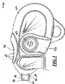
図1〜図8を参照して説明するに、本発明に従う移行テープディスペンサ20(以下、ディスペンサ20とも称する)が示され、ケース22と、供給スプール24と、戻りスプール26と、付着縁部30を有するアプリケータ先端部28とを含んでいる。ディスペンサ20には、何れも図示されない付着層及びキャリヤテープを有する修正テープ32も含まれる。ディスペンサ20内の修正テープ32の走路は供給スプール24を始端とし、戻りスプール26で終端する。修正テープ32は供給スプール24からテープ支柱38を通過してアプリケータ先端部28に、次いで戻りスプール26へと送られる。表面42上に付着縁部30を押し付けると(図7参照)図示しない付着層が表面42に付着され、この付着部分で表面42を隠す。次いで、図示しない修正テープは戻りループ26に収集される。ディスペンサ20には、表面42への付着縁部30の押し付けを緩衝する緩衝体94が含まれる。ディスペンサ20は、修正テープ32に余分な張力が蓄積されないようにするための必要に応じて、供給スプール24を戻りスプール26の回転に関してスリップさせるためのスリップクラッチ機構46が含まれる。
Referring to FIGS. 1-8, a transition tape dispenser 20 (hereinafter also referred to as dispenser 20) according to the present invention is shown, which includes a case 22, a
修正テープ32の図示されない塗布層は数多くの機能を提供し得る。例えば、図示されない付着層は接着材、マーカー材料、あるいは装飾性のコーティング材料であり得る。従って、付着層の図示されない片面を表面42に付着させ、図示されない他方の面に別の機能性を提供させ得る。然し乍ら、開示された実施例では図示されない付着層は修正テープ層であり、以下そのように参照される。図示されない修正テープ層は表面42に付着してこの付着部分で表面42を隠す。図示されない修正テープ層はキャリヤテープの片面に塗布される。キャリヤテープは可撓性のリボンあるいはプラスチックあるいは紙のリボンから構成される。
A coating layer (not shown) of the
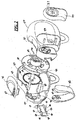
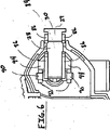
図2を参照するに、ケース22は第1側部47と第2側部49とを含み、これら各側部は相互に取り付けられてディスペンサ20の様々な構成部品を格納する。例示した実施例では第1側部47と第2側部49とは、第1側部47の舌部51が第2側部49の溝53と係合することにより相互に脱着自在に取り付けられる。第2側部49には、第1側部47及び第2側部49を相互に固定するための錠止タブ55が含まれる。錠止タブ55は第2側部47の相当する孔57と係合する。ケース22は所望の形状のものであり得るが、例示した実施例ではユーザーによる快適且つ直感的な操作を提供するための人間工学的な形状とされている。
Referring to FIG. 2, the case 22 includes a
図1及び図2を参照するに、ディスペンサ20は、人差し指グリップパッド31と、親指グリップパッド33と、ケース22に廻動自在に取り付けたアプリケータ先端部保護体35とを含んでいる。人差し指グリップパッド31はケース22の上方部分の、ユーザーがディスペンサ20を使用するに際して代表的に人差し指を配置する場所に配置される。人差し指グリップパッド31と親指グリップパッド33とはケース22の一部であり得、ケースと同じ材料から構成され得、あるいはケース22に取り付けた、あるいはケースに形成した、別の材料製の独立したグリップパッドであり得る。例示した実施例では、人差し指グリップパッド31と親指グリップパッド33とは軟質プラスチック製であり、ケース22に取り付けられる。また、ユーザーがディスペンサ20を保持するときに、ユーザーの指と、人差し指グリップパッド31及び親指グリップパッド33との間に十分なグリップ力が提供されるよう、人差し指グリップパッド31と親指グリップパッド33とはゴム製とし得、各表面上には多数の峰部37が含まれ得る。
Referring to FIGS. 1 and 2, the
アプリケータ先端部保護体35が、非使用時においてアプリケータ先端部28を保護する。図2を参照するに、アプリケータ先端部保護体35はケース22の側方断面形状に全体的に相当する形状を有している。アプリケータ先端部保護体35の各端部39はケース22の第1側部47或いは第2側部49の一方に廻動自在に取り付けられる。従って、アプリケータ先端部保護体35は、前記各端部39を通る図示されない軸線を中心として廻動する。ディスペンサ20を使用する際、アプリケータ先端部保護体35は図1に示す如き開位置に廻動あるいは回転され得る。ディスペンサ20をもはや使用しないときは、ユーザーはアプリケータ先端部保護体35を、アプリケータ先端部28を覆うための閉位置へと番号41で示す方向に回転させることができる。アプリケータ先端部保護体35は、アプリケータ先端部28と、付着縁部30と、修正テープ32とを、外部の物体と接触しないように保護する。アプリケータ先端部28は広汎な保護体によって覆われ得る。例えば、ディスペンサ20は、ケース22の、アプリケータ先端部28を配置する部分と類似形状とした図示されないキャップを含み得る。ユーザーは、このキャップをケース22の相当部分に配置してアプリケータ先端部28を覆うことができる。
The
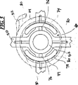
ケース22は、その内部に駆動ホイール50を取り付けるためのシャフト48を含み、駆動ホイール50はこのシャフト48に回転自在に取り付けられるためのセンターハブ52を含んでいる。シャフト48は、例えば本実施例では第2側部49から第1側部47に向けて横方向に伸延する。従って、駆動ホイール50はシャフト48を中心として自由回転し得るが、その他の方向には移動あるいは回転しないようにされる。供給スプール24は駆動ホイール50の供給側58に回転自在に取り付けられ、以下に詳しく説明するように、必要に応じて駆動ホイール50と共に回転し得、あるいは駆動ホイール50に関してスリップし得る。戻りスプール26は駆動ホイール50の戻り側60上に配置される。例示した実施例では戻りスプール26は駆動ホイール50の一体部分を構成し、かくして駆動ホイール50と共に回転する。例示した実施例では戻りスプール26は、駆動ホイール50の戻り側60と一体で且つこの戻り側60から外側に突出する円形棚部62を構成する。円形棚部62は駆動ホイール50と同中心を有し、修正テープ32よりも幅広である。従って、円形棚部62は、修正テープ32の図示されないキャリヤテープを巻き取り様式下に収集するための戻りスプール26を確定する。円形棚部62に巻き付けられる修正テープ32が外れないようにするために、修正テープ32を戻りスプール26上に収容する複数の側壁64が円形棚部62の周囲に設けられる。
The case 22 includes a shaft 48 for attaching the
駆動ホイール50が分与方向66に回転すると供給スプール24から修正テープ32が巻き解かれ、供給スプール24から修正テープが分与される。次いで、図示されないキャリヤテープが戻りスプール26に巻き付けられ、この戻りスプール26上に収集される。従って、修正テープ32は供給スプール24の上部から巻き解かれることによって分与され、戻りスプール26上に、この戻りスプール26の底部から巻き付けられることにより収集される。然し乍ら、上述した修正テープ32の巻き付け及び巻き解きの形態を逆にして同じ結果を得ることが可能である。
When the
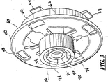
駆動ホイール50が非分与方向(即ち、分与方向66とは逆の方向)に回転しないようにするために、駆動ホイール50は、この駆動ホイール50の戻り側60に半径方向に配置した多数の可撓性タブ68にして、第2側部49の内側に半径方向に配置した多数の戻止め70と係合する可撓性タブ68を含んでいる。可撓性タブ68は楔状先端部72を含み、この楔状先端部72は図4に示されるように同じく楔状の前記戻止め70と係合する。分与方向66において、各楔状先端部72はその傾斜面において戻止め70の傾斜面と係合し、次いでこの傾斜面が可撓性タブ68の可撓性により戻止め70を超えて摺動し、かくして駆動ホイール50の分与方向66での回転を許容する。逆に、駆動ホイール50が非分与方向に回転すると各楔状先端部72の垂直面が戻止め70の垂直面と係合し、駆動ホイール50がこの非分与方向に回転するのを防止する。
In order to prevent the
修正テープ32が供給スプール24から巻き解かれて戻りスプール26上に巻き付けられるに従い、供給スプール24の、この修正テープ32の供給源を含む直径は縮小し、他方、図示されないキャリヤテープの供給源を含む戻りスプールの直径は増大する。供給スプール24と戻りスプール26とは全体に調和回転することから、そうした直径変化によって修正テープ32における張力変化が生じる。スリップクラッチ機構46は、供給スプール24及び戻りスプール26の各直径が変化するに際しての修正テープ32における所望の最大張力を維持する。
As the
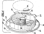
図3及び図5を参照するに、スリップクラッチ機構46は一対の弓状シュー74を含み、この弓状シュー74は供給スプール24の内径と全体に類似した外径を有している。各弓状シュー74は駆動ホイール50の供給側58でセンターハブ52にスポーク76を介して取り付けられる。かくして弓状シュー74は、駆動ホイール50の供給側58で供給スプール24を取り付けるべくセンターハブ52と同中心を有する、点線で示す供給ハブ78の一部を確定する。各弓状シュー74はその幅方向を横断して伸延する一対の峰部80を含み、これら峰部80は供給ハブ78から半径方向外側に若干突出される。更に、各峰部80は供給ハブ78に関して半径方向に等間隔の様式下において配分される。供給スプール24を供給ハブ78に取り付けると各峰部80が弓状シュー74を撓ませ且つ峰部80は偏倚されて供給スプール24の内側周囲部分に接触し、かくして峰部80と供給スプール24の前記内側周囲部分との摩擦接触が維持される。
Referring to FIGS. 3 and 5, the slip clutch mechanism 46 includes a pair of
戻りスプール26の直径が供給スプール24の直径よりも大きくなると修正テープ32は戻りスプール26に巻き付けられるよりも速く供給スプール24から巻き解かれる必要がある。供給スプール24を駆動ホイール50に関してもっと速く回転させるためには、修正テープ32の張力を峰部80と供給スプール24の内側周囲部分との間の摩擦力に十分勝るものとすべきである。従って、供給スプール24は、供給スプール24から巻き解かれる修正テープの長さを戻りスプール26に巻き付けられるテープ長さに同調させるよう、必要に応じて弓状シュー74上でスリップすべきである。
When the diameter of the
戻りスプール26の直径が供給スプール24の直径よりも小さくなると、修正テープ32は戻りスプール26に巻き付けられるよりも遅い速度で供給スプール24から巻き解かれる必要がある。供給スプール24を駆動ホイール50に関してもっと遅く回転させるためには、修正テープ32の張力を峰部80と供給スプール24の内側周囲部分との間の摩擦力に十分勝るものとすべきである。従って、供給スプール24は、供給スプール24から巻き解かれる修正テープの長さを戻りスプール26に巻き付けられるテープ長さと同調させるよう、必要に応じて弓状シュー74上でスリップすべきである。
When the diameter of the
スリップクラッチ機構46は、駆動ホイール50と供給リール24との間のスリップ自在の係合を提供することにより作動する。従って、移行テープディスペンサ20のために様々な既知のスリップクラッチ機構を使用することが可能である。例えば、可撓性材料から構成される図示されないガスケット、O−リング、あるいはワッシャをセンターハブ52に配置して供給スプール24の内側周囲部分と摩擦係合させ得る。また別の実施例ではセンターハブ52が、供給スプール24の内側周囲部分の図示されない複数の戻止めと係合し得る、半径方向に配置した図示されない複数の戻止めを含み得る。
Slip clutch mechanism 46 operates by providing a slippery engagement between
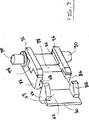
図6及び図8を参照するに、アプリケータ先端部28がケース22の内部にピボット廻動自在に取り付けられている。アプリケータ先端部28の、付着縁部30を含む突出部分29は、修正テープ32が表面42に付着され得るようにケース22から突出される。然し乍ら突出部分29は、修正テープ32を付着縁部30の前後に案内するための楔状を有する。修正テープ32は供給スプール24からアプリケータ先端部28の付着側部84に送られ、付着縁部30を巡った後、アプリケータ先端部28の非付着側部82を離れて戻りスプール26に送られる。アプリケータ先端部28上を移動する間、修正テープ32が付着側部84及び非付着側部82上に維持されるようにするために、アプリケータ先端部28の前記付着側部84及び非付着側部82に取り付けられてアプリケータ先端部の幅部分を境界付けるガイド86を含む。このガイド86もまた、修正テープ32及び図示されないキャリヤテープを夫々付着縁部30の前後に案内する。
Referring to FIGS. 6 and 8, the
図8に示すように、アプリケータ先端部28は、供給スプール24から巻き解かれる修正テープ32の方向に関して全体にほぼ90°の角度をなし、従って、テープ支柱38は供給スプール24からアプリケータ先端部28に修正テープ32を配向すると共に、供給スプール24とアプリケータ先端部28との間のテープ走路で修正テープ32の方向をねじらせる。またテープ支柱38は、修正テープ32をアプリケータ先端部28から戻りスプール26に送り、アプリケータ先端部28と戻りスプール26との間のテープ走路で図示しないキャリヤテープをもよじらせてその方向を変化させる。テープ支柱38は説明した機能を実行するための様々な寸法形状のものであり得る。然し乍ら、例示した実施例ではテープ支柱38はケースに取り付けられ、全体的にシャフト48と平行な円筒状ロッドである。
As shown in FIG. 8, the
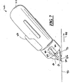
図7を参照するに、修正テープ32が、ユーザーが付着縁部30の付着側部84を表面42に押し付け、次いでディスペンサ20を矢印88の方向に移動させることによりこの表面42に付着されている。修正テープ32が付着縁部30の位置で表面42と接触し、ディスペンサ20が方向88に移動されると、供給スプール24から修正テープ32が繰り出される。他方、付着縁部30が表面42と接触すると修正テープ32の図示されない修正テープの層が付着縁部30の位置で表面42に付着する。戻りスプール26が駆動ホイール50と共に回転することから、図示されないキャリヤテープが戻りスプール26によって引張され、次いでこの戻りスプール26上に巻き付けられて収集される。かくして、ディスペンサ20を矢印88の方向に移動させると図示されない修正テープの層が前記矢印88の方向に沿って表面42に付着し、付着した部分の表面を隠す。
Referring to FIG. 7, the
アプリケータ先端部28は、付着縁部30を表面42に接触させたときにこの付着縁部の位置でアプリケータ先端部28をピボット廻動させるための、ケース22にピボット廻動自在に取り付けたピボットシャフト90を含んでいる。ピボットシャフト90は付着縁部30と平行であり、ケース22から突出する一対のフォーク92にピボット廻動自在に取り付けられる。従って、ピボットシャフト90の各端部は相当するフォーク92の内側へピボット廻動し、かくしてアプリケータ先端部28をピボット廻動させる。
The
アプリケータ先端部28は限定範囲をピボット廻動し、このアプリケータ先端部28と、ケース22の第1側部47との間に配置した緩衝体94によって緩衝される。付着縁部30を表面42に押し付けると、アプリケータ先端部28が図7で矢印93で示す方向に廻動する。アプリケータ先端部28がその休止位置から廻動するとガイド86が緩衝体94と接触し、キャリヤテープが緩衝体94とアプリケータ先端部28の非付着側部82との間を通過することが出来るようになる。アプリケータ先端部28がその休止位置から付着位置にピボット廻動すると、ガイド86が緩衝体94を圧縮することから、アプリケータ先端部28を休止位置に戻そうとする反力が生じる。ピボット廻動量が大きくなると緩衝体94は更に圧縮され、緩衝体94における反力も大きくなる。従って、ユーザーは図示されない修正テープの層を表面42上に一様に付着させるために付着縁部30を表面42に押し付ける力を直感的に感じ且つ判断することができる。
The
緩衝体94は付着縁部30を非一様な表面に押し付ける場合にも、アプリケータ先端部28のピボット廻動に対する緩衝作用を提供する。更には、アプリケータ先端部28の緩衝下のピボット廻動は、付着縁部30と表面42との間の不整合を補償し得る。当業者には、緩衝体94がバネ、ダンパーあるいはその両方の如く作用し得ることを理解されよう。緩衝体94は弾性体であり、ある方向に押し付けられると逆向きの反力を提供する。
The
図9を参照するに、緩衝体94とアプリケータ先端部28とは製造段階において共成型することができる。従って、緩衝体94はワンピース部材であり、ガイド86に共成型され且つブリッジ98により連結された一対の緩衝体側部96を含む。緩衝体94とアプリケータ先端部28と共成型する場合、ブリッジ98は、非付着側部82と面一となるよう、アプリケータ先端部28の非付着側部82における相当寸法の凹所内に嵌入される。
Referring to FIG. 9, the
緩衝体94は、例えば先に説明したようにアプリケータ先端部28と共成型することによってアプリケータ先端部28に連結することが可能である。緩衝体94は、アプリケータ先端部28あるいはケース22の何れかに連結することなくこれらアプリケータ先端部28とケース22との間に配置した別個の緩衝体であり得る。緩衝体94は、アプリケータ先端部28に連結させることなくケース22に連結させ得る。然し乍ら、緩衝体94はアプリケータ先端部28及びケース22とは別の材料から構成させ得る。例示した実施例では緩衝体94はエラストマー体から構成したワンピース型のものとされ得る。緩衝体94は、アプリケータ先端部28とケース22との間において形状付けすることもできる。更には、緩衝体94とアプリケータ先端部28とを、例えば、射出成型法によって製造することも可能である。同様に、緩衝体94とケース22の第1側部47とは、例えば射出成型法によって製造し得る。
以上、本発明を実施例を参照して説明したが、本発明の内で種々の変更をなし得ることを理解されたい。
The
Although the present invention has been described with reference to the embodiments, it should be understood that various modifications can be made within the present invention.
20 移行テープディスペンサ
22 ケース
24 供給スプール
26 戻りスプール
28 アプリケータ先端部
29 突出部分
30 付着縁部
31 人差し指グリップパッド
32 修正テープ
33 親指グリップパッド
35 アプリケータ先端部保護体
37 峰部
38 テープ支柱
39 端部
42 表面
46 スリップクラッチ機構
47 第1側部
48 シャフト
49 第2側部
50 駆動ホイール
51 舌部
52 センターハブ
53 溝
55 錠止タブ
57 孔
58 供給側
60 戻り側
62 円形棚部
64 側壁
68 可撓性タブ
70 戻止め
72 楔状先端部
74 弓状シュー
76 スポーク
78 供給ハブ
80 峰部
82 非付着側部
84 付着側部
86 ガイド
90 ピボットシャフト
92 フォーク
94 緩衝体
98 ブリッジ
DESCRIPTION OF
Claims (31)
ケースと、
該ケース内に回転自在に取り付けられ、付着層とキャリヤテープとを有するテープ供給源を受けるようになっている供給スプールと、
キャリヤテープを収集するようにされ、前記ケース内に回転自在に取り付けた戻りスプールと、
前記ケースにピボット廻動自在に取り付けられ、供給スプールと戻りスプールとの間のテープ走路内に配置され、休止位置と、少なくとも付着位置との間でピボット廻動する実質的に剛性のアプリケータ先端部と、
前記ケース内に配置され、アプリケータのピボット廻動により圧縮され、かくしてアプリケータ先端部を付着位置から休止位置に偏倚させるようになっている緩衝体と、
を含む移行テープディスペンサ。A transition tape dispenser,
Case and
A supply spool rotatably mounted in the case and adapted to receive a tape supply source having an adhesive layer and a carrier tape;
A return spool adapted to collect carrier tape and rotatably mounted in the case;
A substantially rigid applicator tip pivotally attached to the case and disposed in the tape runway between the supply spool and the return spool and pivoting between a rest position and at least an attachment position And
A buffer disposed within the case and compressed by pivoting the applicator , thus biasing the applicator tip from the attachment position to the rest position;
Including transition tape dispenser.
給スプールを駆動ホイールにスリップ自在に連結するようになっているスリップクラッチを更に含む請求項9の移行テープディスペンサ。10. The transition tape dispenser of claim 9, further comprising a slip clutch that slips the supply spool and the return spool to connect the supply spool to the drive wheel.
ケースと、
該ケース内に廻動自在に取り付けられ、供給側と戻り側とを含む駆動ホイールと、
駆動ホイールの供給側に回転自在に取り付けられ、付着層とキャリヤテープとを有するテープを受けるようになっている供給源を含む供給スプールと、
駆動ホイールの戻り側に配置され、キャリヤテープを収集するようになっている戻りスプールと、
ケース内にピボット廻動自在に取り付けられた実質的に剛性のアプリケータ先端部にして、アプリケーター先端部の縁部に関して平行に固定したピボット軸を中心にピボット廻動自在であり、供給スプールと戻りスプールとの間のテープ走路内に配置され、休止位置と、少なくとも付着位置との間でケースに関してピボット廻動するようになっているアプリケータ先端部と、
ケース内でアプリケータ先端部とケースの内面との間に配置された緩衝体にして、付着位置へのアプリケータ先端部のピボット廻動により圧縮され、かくして前記ピボット廻動が該緩衝体によって弾性的に抵抗される緩衝体と、
駆動ホイールの供給側に取り付けられ、複数の突出部分で有するスリップクラッチにして、各突出部分が、駆動ホイールの回転を供給スプールに伝達し、戻りスプールの回転に関して供給ホイールをスリップ自在に回転させるようになっているスリップクラッチと、
を含む移行テープディスペンサ。A transition tape dispenser,
Case and
A drive wheel rotatably mounted in the case and including a supply side and a return side;
A supply spool including a supply mounted rotatably on the supply side of the drive wheel and adapted to receive a tape having an adhesive layer and a carrier tape;
A return spool disposed on the return side of the drive wheel and adapted to collect carrier tape;
A substantially rigid applicator tip that is pivotably mounted in the case, and pivotable around a pivot axis that is fixed in parallel with respect to the edge of the applicator tip. An applicator tip disposed in a tape runway between the spool and adapted to pivot about the case between a rest position and at least an attachment position;
A shock absorber disposed between the applicator tip and the inner surface of the case in the case is compressed by the pivoting motion of the applicator tip to the attachment position, and thus the pivoting motion is elasticized by the shock absorber. A shock-resistant buffer,
A slip clutch attached to the supply side of the drive wheel and having a plurality of protruding parts, each protruding part transmits the rotation of the drive wheel to the supply spool and allows the supply wheel to slip freely with respect to the rotation of the return spool. And slip clutch
Including transition tape dispenser.
Applications Claiming Priority (2)
| Application Number | Priority Date | Filing Date | Title |
|---|---|---|---|
| US10/662,851 US7228882B2 (en) | 2003-09-15 | 2003-09-15 | Tape dispenser with a cushioned applicator tip |
| PCT/US2004/006382 WO2005035412A1 (en) | 2003-09-15 | 2004-03-03 | Tape dispenser with a cushioned applicator tip |
Publications (3)
| Publication Number | Publication Date |
|---|---|
| JP2007505760A JP2007505760A (en) | 2007-03-15 |
| JP2007505760A5 JP2007505760A5 (en) | 2010-06-24 |
| JP4538457B2 true JP4538457B2 (en) | 2010-09-08 |
Family
ID=34274225
Family Applications (1)
| Application Number | Title | Priority Date | Filing Date |
|---|---|---|---|
| JP2006526051A Expired - Fee Related JP4538457B2 (en) | 2003-09-15 | 2004-03-03 | Transition tape dispenser with cushioned applicator tip |
Country Status (10)
| Country | Link |
|---|---|
| US (1) | US7228882B2 (en) |
| EP (1) | EP1663833A1 (en) |
| JP (1) | JP4538457B2 (en) |
| KR (1) | KR20060080199A (en) |
| CN (1) | CN1874947A (en) |
| AU (1) | AU2004279770A1 (en) |
| CA (1) | CA2539075A1 (en) |
| MX (1) | MXPA06002872A (en) |
| TW (1) | TW200510191A (en) |
| WO (1) | WO2005035412A1 (en) |
Families Citing this family (25)
| Publication number | Priority date | Publication date | Assignee | Title |
|---|---|---|---|---|
| JP4411970B2 (en) * | 2003-12-26 | 2010-02-10 | コクヨ株式会社 | Transfer tool |
| JP4644840B2 (en) * | 2005-04-27 | 2011-03-09 | コクヨ株式会社 | Cover locking structure and transfer tool |
| US8263691B2 (en) | 2006-02-21 | 2012-09-11 | Sabic Innovative Plastics Ip B.V. | Release agent for transparent polyimide blends |
| WO2009149538A1 (en) * | 2008-06-10 | 2009-12-17 | Garth Wells | Hand held non-adhesive tape dispenser with friction brakes |
| JP5039662B2 (en) * | 2008-08-19 | 2012-10-03 | ゼネラル株式会社 | Transfer tool |
| US20100071853A1 (en) * | 2008-09-23 | 2010-03-25 | Chien-Lung Wu | Tape Dispenser |
| CN101683802B (en) * | 2008-09-26 | 2011-09-07 | 顺德工业股份有限公司 | Lateral correction belt |
| US20110042506A1 (en) * | 2009-08-19 | 2011-02-24 | Chien-Lung Wu | Device for Changing Orientation of Tape of Tape Transfer Device |
| US8397784B2 (en) | 2010-08-31 | 2013-03-19 | Sanford, L.P. | Correction tape dispenser with variable clutch mechanism |
| MY163858A (en) * | 2010-09-30 | 2017-10-31 | Widetech Mfg Sdn Bhd | A tape device |
| US8578999B2 (en) | 2010-12-29 | 2013-11-12 | Sanford, L.P. | Variable clutch mechanism and correction tape dispenser with variable clutch mechanism |
| US8746313B2 (en) * | 2010-12-29 | 2014-06-10 | Sanford, L.P. | Correction tape re-tensioning mechanism and correction tape dispenser comprising same |
| FR2981057B1 (en) * | 2011-10-10 | 2013-11-29 | Bic Soc | MANUAL RIBBON APPLICATION DEVICE OF A COATING ON AN IMPROVED END SUPPORT |
| US8746316B2 (en) | 2011-12-30 | 2014-06-10 | Sanford, L.P. | Variable clutch mechanism and correction tape dispenser with variable clutch mechanism |
| US8875769B2 (en) | 2012-07-03 | 2014-11-04 | Cory Lee Dean Walker | One-handed combination tape dispenser and applicator |
| JP6247199B2 (en) | 2014-12-09 | 2017-12-13 | 株式会社トンボ鉛筆 | Film transfer tool |
| JP6321537B2 (en) | 2014-12-26 | 2018-05-09 | 株式会社トンボ鉛筆 | Film transfer tool |
| FR3046786B1 (en) | 2016-01-15 | 2018-02-09 | Societe Bic | MANUAL TAPE APPLICATION DEVICE OF A COATING ON A SUPPORT HAVING AN IMPROVED APPLICATION TIP |
| WO2017221490A1 (en) * | 2016-06-24 | 2017-12-28 | 株式会社トンボ鉛筆 | Horizontal pulling type coating film transfer tool |
| US9969590B2 (en) | 2016-06-24 | 2018-05-15 | Tombow Pencil Co., Ltd. | Horizontal-pull coating film transferring tool |
| JP7095856B2 (en) | 2017-07-04 | 2022-07-05 | 株式会社トンボ鉛筆 | Coating film transfer tool |
| KR102418033B1 (en) | 2017-07-04 | 2022-07-07 | 가부시키가이샤 돔보 엔피쓰 | film transfer ball |
| JP7219943B2 (en) | 2018-03-13 | 2023-02-09 | 株式会社トンボ鉛筆 | pressure sensitive transfer correction tape |
| CN110641201A (en) * | 2019-10-10 | 2020-01-03 | 天津大学 | Multifunctional gel ink pen |
| JP2021194891A (en) * | 2020-06-18 | 2021-12-27 | コクヨ株式会社 | Transfer tool |
Family Cites Families (17)
| Publication number | Priority date | Publication date | Assignee | Title |
|---|---|---|---|---|
| DE3638722A1 (en) * | 1986-11-13 | 1988-05-26 | Pelikan Ag | DEVICE FOR APPLYING AN ADHESIVE FILM |
| US5009739A (en) * | 1988-06-22 | 1991-04-23 | Monarch Marking Systems, Inc. | Hand-held labeler |
| CA2033057A1 (en) * | 1989-05-20 | 1990-11-21 | Takumi Murasaki | Transfer film transfer device |
| JP3306464B2 (en) * | 1994-12-26 | 2002-07-24 | ユニオンケミカー株式会社 | Transfer device |
| JP3520138B2 (en) * | 1995-06-16 | 2004-04-19 | ゼネラル株式会社 | Coating film transfer tool and transfer tape refilling method in coating film transfer tool |
| DE19609533C1 (en) * | 1996-03-11 | 1997-02-27 | Pritt Produktionsgesellschaft | Winding-spool drive mechanism for transfer tape |
| JPH11227385A (en) * | 1998-02-12 | 1999-08-24 | Fujicopian Co Ltd | Coating film transfer implement |
| JP2000238957A (en) * | 1999-02-22 | 2000-09-05 | Tombow Pencil Co Ltd | Transfer tape applicator |
| JP3618586B2 (en) | 1999-06-25 | 2005-02-09 | 株式会社壽 | Film transfer tool |
| AU773037B2 (en) * | 2000-02-25 | 2004-05-13 | Societe Bic | A hand-held device for transferring a film onto a substrate, comprising a concealable application member |
| AU769504B2 (en) * | 2000-02-25 | 2004-01-29 | Societe Bic | Hand-held device for transferring a film and having an angular application member |
| DE60142457D1 (en) * | 2000-02-25 | 2010-08-05 | Bic Soc | A handheld device for transferring a film from a backing tape to a substrate having backing tape rails disposed close to each other |
| US6453968B1 (en) * | 2000-09-28 | 2002-09-24 | Tsang-Hung Hsu | Dispensing device for double-face adhesive tape |
| US6681830B1 (en) * | 2000-11-28 | 2004-01-27 | Henkel Consumer Adhesives, Inc. | Hand-held adhesive tape dispenser |
| EP1295834B1 (en) | 2001-09-19 | 2008-05-21 | Société BIC | A hand-held device for applying a film of adhesive, covering or coloured material onto a substrate |
| JP4603738B2 (en) * | 2001-09-28 | 2010-12-22 | プラス株式会社 | Coating film transfer tool |
| US20040033353A1 (en) * | 2002-03-14 | 2004-02-19 | You Kwang Ho | Adhesive tape |
-
2003
- 2003-09-15 US US10/662,851 patent/US7228882B2/en active Active
-
2004
- 2004-03-03 KR KR1020067005235A patent/KR20060080199A/en not_active Application Discontinuation
- 2004-03-03 JP JP2006526051A patent/JP4538457B2/en not_active Expired - Fee Related
- 2004-03-03 CN CNA2004800325474A patent/CN1874947A/en active Pending
- 2004-03-03 EP EP04716856A patent/EP1663833A1/en not_active Withdrawn
- 2004-03-03 MX MXPA06002872A patent/MXPA06002872A/en active IP Right Grant
- 2004-03-03 WO PCT/US2004/006382 patent/WO2005035412A1/en active Search and Examination
- 2004-03-03 CA CA002539075A patent/CA2539075A1/en not_active Abandoned
- 2004-03-03 AU AU2004279770A patent/AU2004279770A1/en not_active Abandoned
- 2004-05-04 TW TW093112539A patent/TW200510191A/en unknown
Also Published As
| Publication number | Publication date |
|---|---|
| US20050056374A1 (en) | 2005-03-17 |
| CN1874947A (en) | 2006-12-06 |
| AU2004279770A1 (en) | 2005-04-21 |
| US7228882B2 (en) | 2007-06-12 |
| CA2539075A1 (en) | 2005-04-21 |
| MXPA06002872A (en) | 2006-06-05 |
| JP2007505760A (en) | 2007-03-15 |
| KR20060080199A (en) | 2006-07-07 |
| EP1663833A1 (en) | 2006-06-07 |
| WO2005035412A1 (en) | 2005-04-21 |
| TW200510191A (en) | 2005-03-16 |
Similar Documents
| Publication | Publication Date | Title |
|---|---|---|
| JP4538457B2 (en) | Transition tape dispenser with cushioned applicator tip | |
| US7681616B2 (en) | Correction tape applicator tip with cylindrical projection | |
| CA2750349C (en) | Dispenser for length material | |
| US5792263A (en) | Tape cartridge for coating film transfer tool and coating film transfer tool containing the cartridge | |
| US5490898A (en) | Coating film transfer tool | |
| JP2007505760A5 (en) | ||
| JP5850951B2 (en) | Correction tape dispenser and correction tape re-tensioning method in correction tape dispenser | |
| US8746316B2 (en) | Variable clutch mechanism and correction tape dispenser with variable clutch mechanism | |
| JPH09104562A (en) | Clutch mechanism for paint film transfer implement and paint film transfer implement | |
| JP5873088B2 (en) | Correction tape dispenser with variable clutch mechanism | |
| JP2019014086A (en) | Coating film transfer implement | |
| EP1332998B1 (en) | Dispenser of adhesive tape, correction tape and the like | |
| MXPA06008038A (en) | Correction tape applicator tip with cylindrical projection | |
| EP2927172A1 (en) | A tape device | |
| JPH09104563A (en) | Tape rewinding mechanism for paint film transfer implement and paint film transfer implement | |
| JPH08119523A (en) | Tape holder |
Legal Events
| Date | Code | Title | Description |
|---|---|---|---|
| A521 | Request for written amendment filed |
Free format text: JAPANESE INTERMEDIATE CODE: A523 Effective date: 20070227 |
|
| A621 | Written request for application examination |
Free format text: JAPANESE INTERMEDIATE CODE: A621 Effective date: 20070227 |
|
| A131 | Notification of reasons for refusal |
Free format text: JAPANESE INTERMEDIATE CODE: A131 Effective date: 20091201 |
|
| A601 | Written request for extension of time |
Free format text: JAPANESE INTERMEDIATE CODE: A601 Effective date: 20100226 |
|
| A602 | Written permission of extension of time |
Free format text: JAPANESE INTERMEDIATE CODE: A602 Effective date: 20100305 |
|
| A601 | Written request for extension of time |
Free format text: JAPANESE INTERMEDIATE CODE: A601 Effective date: 20100401 |
|
| A602 | Written permission of extension of time |
Free format text: JAPANESE INTERMEDIATE CODE: A602 Effective date: 20100408 |
|
| A524 | Written submission of copy of amendment under article 19 pct |
Free format text: JAPANESE INTERMEDIATE CODE: A524 Effective date: 20100506 |
|
| TRDD | Decision of grant or rejection written | ||
| A01 | Written decision to grant a patent or to grant a registration (utility model) |
Free format text: JAPANESE INTERMEDIATE CODE: A01 Effective date: 20100525 |
|
| A01 | Written decision to grant a patent or to grant a registration (utility model) |
Free format text: JAPANESE INTERMEDIATE CODE: A01 |
|
| A61 | First payment of annual fees (during grant procedure) |
Free format text: JAPANESE INTERMEDIATE CODE: A61 Effective date: 20100621 |
|
| FPAY | Renewal fee payment (event date is renewal date of database) |
Free format text: PAYMENT UNTIL: 20130625 Year of fee payment: 3 |
|
| R150 | Certificate of patent or registration of utility model |
Free format text: JAPANESE INTERMEDIATE CODE: R150 |
|
| R250 | Receipt of annual fees |
Free format text: JAPANESE INTERMEDIATE CODE: R250 |
|
| R250 | Receipt of annual fees |
Free format text: JAPANESE INTERMEDIATE CODE: R250 |
|
| R250 | Receipt of annual fees |
Free format text: JAPANESE INTERMEDIATE CODE: R250 |
|
| LAPS | Cancellation because of no payment of annual fees |