JP4536621B2 - Decoding device and decoding method - Google Patents
Decoding device and decoding method Download PDFInfo
- Publication number
- JP4536621B2 JP4536621B2 JP2005232484A JP2005232484A JP4536621B2 JP 4536621 B2 JP4536621 B2 JP 4536621B2 JP 2005232484 A JP2005232484 A JP 2005232484A JP 2005232484 A JP2005232484 A JP 2005232484A JP 4536621 B2 JP4536621 B2 JP 4536621B2
- Authority
- JP
- Japan
- Prior art keywords
- error
- encoded data
- transform coefficient
- modified
- transform
- Prior art date
- Legal status (The legal status is an assumption and is not a legal conclusion. Google has not performed a legal analysis and makes no representation as to the accuracy of the status listed.)
- Expired - Fee Related
Links
Images


Abstract
Description
本発明は、音響信号などの信号を予め定めたフレーム単位で変換した変換係数を符号化した符号化データを受信し、この符号化データを復号化する復号装置、および復号方法に関する。 The present invention relates to a decoding apparatus and a decoding method for receiving encoded data obtained by encoding a conversion coefficient obtained by converting a signal such as an acoustic signal in a predetermined frame unit and decoding the encoded data.
現在、音声・音響信号を高効率に圧縮して符号化する方法、装置は数多く存在する。音声・音響符号化方式は、時間領域で符号化する方式と、何らかの変換規則(例えば、離散フーリエ変換(DFT:Discrete Fourier Transform)や離散コサイン変換(DCT:Discrete Cosine Transform)など)に従って変換され、その変換領域で符号化する方式(変換符号化)とに大別できる。 Currently, there are many methods and apparatuses for compressing and encoding speech / acoustic signals with high efficiency. The speech / acoustic encoding method is converted in accordance with a method of encoding in the time domain and some conversion rules (for example, discrete Fourier transform (DFT), discrete cosine transform (DCT), etc.) It can be roughly classified into a method of encoding in the conversion region (conversion encoding).
これらDFT及びDCTは、代表的な変換規則であって、時間領域と周波数領域との間で変換する規則(時間−周波数変換方式)がある。この時間−周波数変換方式は、時間領域において、所定個数のサンプルをまとめて変換フレームが構成され、この変換フレームに対して変換規則が適用され、周波数領域での変換係数が得られるものである。 These DFT and DCT are typical conversion rules, and there is a rule for converting between the time domain and the frequency domain (time-frequency conversion method). In this time-frequency conversion method, a predetermined number of samples are collected in the time domain to form a conversion frame, and a conversion rule is applied to the conversion frame to obtain a conversion coefficient in the frequency domain.
この変換係数を圧縮符号化する方式が変換符号化方式であり、代表的な変換符号化方式の音声・音響信号符号化としては、ISO/IECで規格化されたMPEG-2Audio AAC (Advanced Audio Coding)方式がある(例えば、非特許文献1参照)。MPEG-2 Audio AAC方式では、修正離散コサイン変換(MDCT: Modified Discrete CosineTransform)と呼ばれる変換規則を用いており、この変換規則も時間−周波数変換方式を採用している。変換符号化方式の特徴は、時間領域での冗長を周波数領域で局所化し、周波数領域で局所的に情報を割り当てることで高能率の圧縮を行うことができる点にある。 A method for compressing and encoding this transform coefficient is a transform coding method, and a typical transform coding method for audio / acoustic signal coding is MPEG-2 Audio AAC (Advanced Audio Coding) standardized by ISO / IEC. ) Method (for example, see Non-Patent Document 1). The MPEG-2 Audio AAC system uses a conversion rule called Modified Discrete Cosine Transform (MDCT), and this conversion rule also uses a time-frequency conversion system. A feature of the transform coding method is that high-efficiency compression can be performed by localizing redundancy in the time domain and assigning information locally in the frequency domain.
また、近年のインターネットや携帯電話をはじめとする無線通信の普及によって、これら変換符号化方式の誤り耐性の向上も重要な課題となっており、誤りが生じた区間の復号信号を受信側で作り出す様々なコンシールメント技術が提案されている。非特許文献2には、代表的なコンシールメント技術として、ミュート、複写、雑音置換および予測があげられている。この処理を実現する具体的な構成について図14に示す。
In addition, with the spread of wireless communications such as the Internet and mobile phones in recent years, it has become an important issue to improve the error tolerance of these transform coding systems, and a decoded signal in a section where an error has occurred is generated on the receiving side. Various concealment techniques have been proposed. Non-Patent
図14は、コンシールメント技術を実現することのできる復号装置6のブロック図である。受信した符号化データに誤りがない場合は受信した符号化データを復号部1が復号して変換係数を得て、バッファ部2に記憶させる。そして、逆変換部3は、バッファ部2から変換係数を取り出し、周波数領域から時間領域への信号に変換して、復号音として出力する。受信した符号化データに誤りが生じている場合は、その符号化データの変換係数に基づいて、変換係数生成部5が修正変換係数を生成し、逆変換部3は生成した変換係数を逆変換して誤りが生じたフレームに対応する復号信号を得て、復号音として出力する。
しかしながら、従来のコンシールメント技術は、非特許文献2にも記述があるように変換規則にMDCTのような位相情報がない変換規則を採用すると、複写や雑音置換の方法では当該区間に不連続が生じ、復号音の品質が劣化することがある。また、予測する技術においては、時間領域にて計算することから上記のような不連続は生じにくい反面、相関計算など多くの計算量を必要としてしまい、処理に負荷がかかるという問題がある。
However, in the conventional concealment technique, as described in Non-Patent
そこで、上述の課題を解決するために、周波数領域で計算が可能で、かつ再生信号の不連続性を低減したコンシールメントを行うことができる復号装置、および復号方法を実現することを目的とする。 Accordingly, in order to solve the above-described problem, an object is to realize a decoding apparatus and a decoding method that can perform concealment that can be calculated in the frequency domain and that reduces the discontinuity of the reproduction signal. .
上述の課題を解決するために、本発明の復号装置は、予め定められたフレーム単位で変換された変換係数が符号化された符号化データを入力し、復号化して通常変換係数を得る復号手段と、符号化データの誤りを示す誤り検出情報が符号化データに誤りがないことを示している場合には、上記復号手段により復号された通常変換係数を逆変換して通常復号信号を得る第1の逆変換手段と、符号化データの誤りを示す誤り検出情報が符号化データに誤りがあることを示している場合には、上記復号手段により復号された誤りのあるフレームの近傍にあるフレームの通常変換係数に基づいて当該誤りのある符号化データに対応するフレームの修正変換係数を算出する変換係数算出手段と、上記変換係数算出手段により算出された修正変換係数に対して、隣接するフレームと位相が一致するように逆変換して修正復号信号を得る第2の逆変換手段と、符号化データの誤りを示す誤り検出情報が符号化データに誤りがないことを示している場合には、上記第1の逆変換手段により逆変換して得られた通常復号信号に対する再生信号を生成し、上記誤り検出情報が符号化データに誤りがあることを示している場合に、上記第2の逆変換手段により逆変換されて得られた修正復号信号に対する再生信号を生成する生成手段と、を備えている。 In order to solve the above-mentioned problem, the decoding apparatus of the present invention receives a coded data obtained by coding a transform coefficient transformed in a predetermined frame unit and decodes it to obtain a normal transform coefficient. If the error detection information indicating an error in the encoded data indicates that there is no error in the encoded data, the normal conversion coefficient decoded by the decoding means is inversely converted to obtain a normal decoded signal. 1 and when the error detection information indicating an error in the encoded data indicates that there is an error in the encoded data, a frame in the vicinity of the erroneous frame decoded by the decoding means Conversion coefficient calculation means for calculating a corrected conversion coefficient of a frame corresponding to the encoded data having the error based on the normal conversion coefficient, and the correction conversion coefficient calculated by the conversion coefficient calculation means. Second inverse transform means for obtaining a modified decoded signal by inverse transform so that the phase of an adjacent frame matches, and error detection information indicating an error in the encoded data indicates that the encoded data has no error. If a reproduced signal is generated for the normal decoded signal obtained by inverse transformation by the first inverse transformation means, and the error detection information indicates that there is an error in the encoded data Generating means for generating a reproduction signal for the modified decoded signal obtained by inverse conversion by the second inverse conversion means.
また、本発明の復号方法は、予め定められたフレーム単位で変換された変換係数が符号化された符号化データを入力し、復号化して通常変換係数を得る復号ステップと、符号化データの誤りを示す誤り検出情報が符号化データに誤りがないことを示している場合には、上記復号ステップにより復号された通常変換係数を逆変換して通常復号信号を得る第1の逆変換ステップと、符号化データの誤りを示す誤り検出情報が符号化データに誤りがあることを示している場合には、上記復号ステップにより復号された誤りのあるフレームの近傍にあるフレームの通常変換係数に基づいて当該誤りのある符号化データに対応するフレームの修正変換係数を算出する変換係数算出ステップと、上記変換係数算出ステップにより算出された修正変換係数に対して、隣接するフレームと位相が一致するように逆変換して修正復号信号を得る第2の逆変換ステップと、符号化データの誤りを示す誤り検出情報が符号化データに誤りがないことを示している場合には、上記第1の逆変換ステップにより逆変換して得られた通常復号信号に対する再生信号を生成し、上記誤り検出情報が符号化データに誤りがあることを示している場合に、上記第2の逆変換ステップにより逆変換されて得られた修正復号信号に対する再生信号を生成する生成ステップと、を備えている。 In addition, the decoding method of the present invention includes a decoding step in which encoded data obtained by encoding a transform coefficient converted in a predetermined frame unit is input and decoded to obtain a normal transform coefficient, and an error in the encoded data When the error detection information indicating that there is no error in the encoded data, a first inverse conversion step of inversely transforming the normal transform coefficient decoded by the decoding step to obtain a normal decoded signal; When the error detection information indicating the error of the encoded data indicates that the encoded data has an error, the error detection information is based on the normal transform coefficient of the frame in the vicinity of the erroneous frame decoded by the decoding step. A transform coefficient calculating step for calculating a corrected transform coefficient of a frame corresponding to the encoded data having the error, and the modified transform coefficient calculated by the transform coefficient calculating step. Then, a second inverse transformation step that obtains a corrected decoded signal by performing inverse transformation so that the phase of the adjacent frame matches, and error detection information indicating an error in the encoded data indicates that there is no error in the encoded data. In a case where a reproduction signal is generated for the normal decoded signal obtained by performing the inverse transformation in the first inverse transformation step, and the error detection information indicates that the encoded data has an error And a generation step of generating a reproduction signal for the modified decoded signal obtained by the inverse transformation by the second inverse transformation step.
この発明によれば、予め定められたフレーム単位で変換された変換係数が符号化された符号化データを入力し、復号化して通常変換係数を得る。そして、誤り検出情報が符号化データに誤りがないことを示している場合には、復号された通常変換係数を逆変換して通常復号信号を得て、符号化データの誤りを示す誤り検出情報が、復号された符号化データに誤りがあることを示している場合には、当該誤りのあるフレームの近傍にあるフレームの通常変換係数に基づいて当該誤りのある符号化データに対応するフレームの修正変換係数を算出する。そして、算出された修正変換係数に対して、隣接するフレームと位相が一致するように逆変換して修正復号信号を得る。 According to the present invention, encoded data obtained by encoding a transform coefficient converted in a predetermined frame unit is input and decoded to obtain a normal transform coefficient. If the error detection information indicates that there is no error in the encoded data, an error detection information indicating an error in the encoded data is obtained by inversely converting the decoded normal transform coefficient to obtain a normal decoded signal. Indicates that there is an error in the decoded encoded data, the frame corresponding to the erroneous encoded data is based on the normal transform coefficient of the frame in the vicinity of the erroneous frame. A corrected conversion coefficient is calculated. Then, the calculated modified transform coefficient is inversely transformed so that the phase thereof matches that of an adjacent frame to obtain a modified decoded signal.
符号化データの誤りを示す誤り検出情報が符号化データに誤りがないことを示している場合には、逆変換して得られた通常復号信号に対する再生信号を生成し、誤り検出情報が符号化データに誤りがあることを示している場合に、逆変換されて得られた修正復号信号に対する再生信号を生成することができる。これにより、フレーム間の不連続性が軽減した再生信号を生成することができる。 If the error detection information indicating an error in the encoded data indicates that there is no error in the encoded data, a reproduction signal for the normal decoded signal obtained by inverse conversion is generated, and the error detection information is encoded. When the data indicates that there is an error, it is possible to generate a reproduction signal for the modified decoded signal obtained by inverse transformation. Thereby, it is possible to generate a reproduction signal with reduced discontinuity between frames.
また、本発明の復号装置は、予め定められたフレーム単位で変換された変換係数が符号化された符号化データを入力し、復号化して通常変換係数を得る復号手段と、符号化データの誤りを示す誤り検出情報が符号化データに誤りがあることを示している場合には、上記復号手段により復号された誤りのあるフレームの近傍にあるフレームの通常変換係数を用いて第1の修正変換係数を算出する第1の変換係数算出手段と、上記誤り検出情報が符号化データに誤りがあることを示している場合には、上記復号手段により復号された誤りのあるフレームの近傍にあるフレームの通常変換係数を用いて第2の修正変換係数を算出する第2の変換係数算出手段と、上記誤り検出情報が符号化データに誤りがないことを示している場合には、上記復号手段から出力された変換係数を逆変換して通常復号信号を得て、誤り検出情報が符号化データに誤りがあることを示している場合には、上記第1の変換係数算出手段により算出された第1の修正変換係数を逆変換して第1の修正復号信号を得る第1の逆変換手段と、上記第2の変換係数算出手段により算出された第2の修正変換係数を隣接するフレームと位相が一致するように逆変換して第2の修正復号信号を得る第2の逆変換手段と、上記誤り検出情報が符号化データに誤りがあることを示している場合には、上記第1の逆変換手段により逆変換された第1の修正復号信号と上記第2の逆変換手段により逆変換された第2の修正復号信号とを合成して再生信号を生成し、上記誤り検出情報が符号化データに誤りがないことを示した場合には、上記第1の逆変換手段により逆変換された通常復号信号から再生信号を生成する生成手段と、を備えている。 The decoding apparatus of the present invention also includes a decoding means for inputting encoded data obtained by encoding a transform coefficient converted in a predetermined frame unit and decoding to obtain a normal transform coefficient, and an error in the encoded data. When the error detection information indicating that there is an error in the encoded data, the first correction transform is performed using the normal transform coefficient of the frame in the vicinity of the erroneous frame decoded by the decoding means. A first transform coefficient calculating means for calculating a coefficient, and a frame in the vicinity of an erroneous frame decoded by the decoding means when the error detection information indicates that there is an error in the encoded data Second transform coefficient calculating means for calculating the second modified transform coefficient using the normal transform coefficient, and the decoding means if the error detection information indicates that there is no error in the encoded data When a normal decoded signal is obtained by inversely transforming the transform coefficient output from, and the error detection information indicates that there is an error in the encoded data, it is calculated by the first transform coefficient calculating means. A first inverse transform unit that inversely transforms the first modified transform coefficient to obtain a first modified decoded signal; an adjacent frame obtained by calculating the second modified transform coefficient calculated by the second transform coefficient calculating unit; A second inverse transforming means for obtaining a second modified decoded signal by performing an inverse transform so that the phases match, and when the error detection information indicates that there is an error in the encoded data, the first The first modified decoded signal inversely transformed by the inverse transform means and the second modified decoded signal inversely transformed by the second inverse transform means are combined to generate a reproduction signal, and the error detection information is If there is no error in the encoded data, And a, a generating means for generating a reproduction signal from the inverse transformed normally decoded signal by the first inverse transformation unit.
また、本発明の復号方法は、予め定められたフレーム単位で変換された変換係数が符号化された符号化データを入力し、復号化して通常変換係数を得る復号ステップと、符号化データの誤りを示す誤り検出情報が符号化データに誤りがあることを示している場合には、上記復号ステップにより復号された誤りのあるフレームの近傍にあるフレームの通常変換係数を用いて第1の修正変換係数を算出する第1の変換係数算出ステップと、上記誤り検出情報が符号化データに誤りがあることを示している場合には、上記復号ステップにより復号された誤りのあるフレームの近傍にあるフレームの通常変換係数を用いて第2の修正変換係数を算出する第2の変換係数算出ステップと、上記誤り検出情報が符号化データに誤りがないことを示している場合には、上記復号ステップから出力された変換係数を逆変換して通常復号信号を得て、誤り検出情報が符号化データに誤りがあることを示している場合には、上記第1の変換係数算出ステップにより算出された第1の修正変換係数を逆変換して第1の修正復号信号を得る第1の逆変換ステップと、上記第2の変換係数算出ステップにより算出された第2の修正変換係数を隣接するフレームと位相が一致するように逆変換して第2の修正復号信号を得る第2の逆変換ステップと、上記誤り検出情報が符号化データに誤りがあることを示している場合には、上記第1の逆変換ステップにより逆変換された第1の修正復号信号と上記第2の逆変換ステップにより逆変換された第2の修正復号信号とを合成して再生信号を生成し、上記誤り検出情報が符号化データに誤りがないことを示した場合には、上記第1の逆変換ステップにより逆変換された通常復号信号から再生信号を生成する生成ステップと、を備えている。 In addition, the decoding method of the present invention includes a decoding step in which encoded data obtained by encoding a transform coefficient converted in a predetermined frame unit is input and decoded to obtain a normal transform coefficient, and an error in the encoded data When the error detection information indicating that there is an error in the encoded data, the first modified transform is performed using the normal transform coefficient of the frame in the vicinity of the frame with the error decoded by the decoding step. A first transform coefficient calculating step for calculating a coefficient, and if the error detection information indicates that there is an error in the encoded data, a frame in the vicinity of the erroneous frame decoded by the decoding step A second transform coefficient calculating step for calculating a second modified transform coefficient using the normal transform coefficient, and when the error detection information indicates that the encoded data has no error. In this case, the transform coefficient output from the decoding step is inversely transformed to obtain a normal decoded signal, and when the error detection information indicates that there is an error in the encoded data, the first transform A first inverse transform step for inversely transforming the first modified transform coefficient calculated in the coefficient calculation step to obtain a first modified decoded signal; and a second modification calculated in the second transform coefficient calculation step A second inverse transformation step for obtaining a second modified decoded signal by inversely transforming the transform coefficient so that the phase thereof matches that of an adjacent frame; and the error detection information indicates that the encoded data has an error. In this case, a reproduction signal is generated by synthesizing the first modified decoded signal inversely transformed by the first inverse transformation step and the second modified decoded signal inversely transformed by the second inverse transformation step. The error detection information is If it demonstrated that there is no error in the No. of data includes a generating step of generating a reproduction signal from the inverse transformed normally decoded signal by the first inverse transformation step.
この発明によれば、予め定められたフレーム単位で変換された変換係数を符号化した符号化データを入力し、復号化して通常変換係数を得て、復号化された誤りのあるフレームの近傍にあるフレームの通常変換係数を用いて第1の修正変換係数を算出し、当該誤りのある符号化データの近傍にあるフレームを用いて第2の修正変換係数を算出する。 According to the present invention, encoded data obtained by encoding a transform coefficient converted in a predetermined frame unit is input and decoded to obtain a normal transform coefficient. A first modified transform coefficient is calculated using a normal transform coefficient of a certain frame, and a second modified transform coefficient is calculated using a frame in the vicinity of the erroneous encoded data.
そして、誤り検出情報が符号化データに誤りがないことを示している場合には、通常変換係数を逆変換して通常復号信号を得て、誤り検出情報が符号化データに誤りがあることを示している場合には、第1の修正変換係数を逆変換して第1の修正復号信号を得て、第2の修正変換係数を隣接するフレームと位相が一致するように逆変換して第2の修正復号信号を得る。そして、符号化データの誤りを示す誤り検出情報が符号化データに誤りがあることを示している場合には、第1の修正復号信号と第2の修正復号信号とを合成して再生信号を生成し、誤り検出情報が符号化データに誤りがないことを示した場合には、通常復号信号から再生信号を生成することができる。これにより、精度の良いフレーム間の不連続性が軽減した再生信号を生成することができる。 If the error detection information indicates that there is no error in the encoded data, the normal conversion coefficient is inversely converted to obtain a normal decoded signal, and the error detection information indicates that the encoded data has an error. In the case shown, the first modified transform coefficient is inversely transformed to obtain a first modified decoded signal, and the second modified transform coefficient is inversely transformed so that the phase thereof matches that of an adjacent frame. 2 modified decoded signals are obtained. If the error detection information indicating an error in the encoded data indicates that there is an error in the encoded data, the first modified decoded signal and the second modified decoded signal are combined to generate a reproduction signal. When the error detection information is generated and the encoded data indicates that there is no error, a reproduction signal can be generated from the normal decoded signal. Thereby, it is possible to generate a reproduction signal with reduced discontinuity between frames with high accuracy.
また、本発明の復号装置は、予め定められたフレーム単位で変換された変換係数が符号化された符号化データを入力し、復号化して通常変換係数を得る復号手段と、符号化データの誤りを示す誤り検出情報が符号化データに誤りがあることを示している場合には、上記復号手段により復号化された誤りのあるフレームの近傍にあるフレームの通常変換係数を用いて第1の修正変換係数を算出する第1の変換係数算出手段と、符号化データの誤りを示す誤り検出情報が符号化データに誤りがあることを示している場合には、上記復号手段により復号化された誤りのあるフレームの近傍にあるフレームの通常変換係数を用いて第2の修正変換係数を算出する第2の変換係数算出手段と、符号化データに誤りがあることを示す誤り検出情報が符号化データに誤りがあることを示している場合には、予め定めた条件に基づいて、上記第1の変換係数生成手段により算出される第1の修正変換係数、または上記第2の変換係数生成手段により算出される第2の修正変換係数のいずれか一方のみを出力するように選択する選択手段と、上記誤り検出情報が符号化データに誤りがないことを示している場合、上記復号手段から出力された通常変換係数を逆変換して通常復号信号を得て、上記誤り検出情報が符号化データに誤りがあることを示している場合であって、上記選択手段により第1の修正変換係数を出力するように選択された場合、上記第1の変換係数算出手段により算出された第1の修正変換係数を逆変換して第1の修正復号信号を得る第1の逆変換手段と、上記選択手段により第2の修正変換係数を出力するように選択された場合、上記第2の変換係数算出手段により算出された第2の修正変換係数を隣接するフレームと位相が一致するように逆変換して第2の修正復号信号を得る第2の逆変換手段と、誤り検出情報が符号化データに誤りがないことを示している場合、上記第1の逆変換手段により逆変換された通常復号信号に基づいて再生信号を生成し、誤り検出情報が符号化データに誤りがあることを示している場合であって、上記選択手段により第1の修正変換係数を出力するように選択された場合、第1の修正復号信号に基づいて再生信号を生成し、誤り検出情報が符号化データに誤りがあることを示している場合であって、上記選択手段により第2の修正変換係数を出力するように選択された場合、上記第2の逆変換手段により逆変換された第2の修正復号信号に基づいて再生信号を生成する生成手段と、を備えている。 The decoding apparatus of the present invention also includes a decoding means for inputting encoded data obtained by encoding a transform coefficient converted in a predetermined frame unit and decoding to obtain a normal transform coefficient, and an error in the encoded data. If the error detection information indicating that there is an error in the encoded data, the first correction is performed using the normal transform coefficient of the frame in the vicinity of the erroneous frame decoded by the decoding means. A first transform coefficient calculating means for calculating a transform coefficient, and an error decoded by the decoding means when the error detection information indicating an error in the encoded data indicates that the encoded data has an error. Second transform coefficient calculating means for calculating a second corrected transform coefficient using a normal transform coefficient of a frame in the vicinity of a certain frame, and error detection information indicating that the encoded data has an error The first modified conversion coefficient calculated by the first conversion coefficient generation means or the second conversion coefficient generation based on a predetermined condition. Selecting means for selecting to output only one of the second modified transform coefficients calculated by the means, and when the error detection information indicates that the encoded data has no error, from the decoding means A normal decoded signal is obtained by inversely transforming the output normal transform coefficient, and the error detection information indicates that there is an error in the encoded data. The first inverse transform means for inversely transforming the first modified transform coefficient calculated by the first transform coefficient calculating means to obtain the first modified decoded signal; Second correction by selection means When it is selected to output transform coefficients, the second modified decoding coefficient calculated by the second transform coefficient calculating means is inversely transformed so that the phase of the second modified transform coefficient coincides with that of the adjacent frame, and second modified decoding is performed. A second inverse transform means for obtaining a signal, and when the error detection information indicates that the encoded data has no error, a reproduced signal is obtained based on the normal decoded signal inversely transformed by the first inverse transform means. When the error detection information is generated and the error detection information indicates that there is an error in the encoded data, and the selection means selects to output the first modified transform coefficient, the first modified decoded signal And when the error detection information indicates that there is an error in the encoded data and the selection means selects to output the second modified transform coefficient, The second inverse conversion hand And a, a generating means for generating a reproduced signal based on the inverse transformed second correction decoded signal by.
また、本発明の復号方法は、予め定められたフレーム単位で変換された変換係数が符号化された符号化データを入力し、復号化して通常変換係数を得る復号ステップと、符号化データの誤りを示す誤り検出情報が符号化データに誤りがあることを示している場合には、前記復号ステップにより復号化された誤りのあるフレームの近傍にあるフレームの通常変換係数を用いて第1の修正変換係数を算出する第1の変換係数算出ステップと、符号化データの誤りを示す誤り検出情報が符号化データに誤りがあることを示している場合には、前記復号ステップにより復号化された誤りのあるフレームの近傍にあるフレームの通常変換係数を用いて第2の修正変換係数を算出する第2の変換係数算出ステップと、符号化データに誤りがあることを示す誤り検出情報が符号化データに誤りがあることを示している場合には、予め定めた条件に基づいて、前記第1の変換係数生成ステップにより算出される第1の修正変換係数、または前記第2の変換係数生成ステップにより算出される第2の修正変換係数のいずれか一方のみを出力するように選択する選択ステップと、前記誤り検出情報が符号化データに誤りがないことを示している場合、前記復号ステップから出力された通常変換係数を逆変換して通常復号信号を得て、前記誤り検出情報が符号化データに誤りがあることを示している場合であって、前記選択ステップにより第1の修正変換係数を出力するように選択された場合、前記第1の変換係数算出ステップにより算出された第1の修正変換係数を逆変換して第1の修正復号信号を得る第1の逆変換ステップと、前記選択ステップにより第2の修正変換係数を出力するように選択された場合、前記第2の変換係数算出ステップにより算出された第2の修正変換係数を隣接するフレームと位相が一致するように逆変換して第2の修正復号信号を得る第2の逆変換ステップと、誤り検出情報が符号化データに誤りがないことを示している場合、前記第1の逆変換ステップにより逆変換された通常復号信号に基づいて再生信号を生成し、誤り検出情報が符号化データに誤りがあることを示している場合であって、前記選択ステップにより第1の修正変換係数を出力するように選択された場合、第1の修正復号信号に基づいて再生信号を生成し、誤り検出情報が符号化データに誤りがあることを示している場合であって、前記選択ステップにより第2の修正変換係数を出力するように選択された場合、前記第2の逆変換ステップにより逆変換された第2の修正復号信号に基づいて再生信号を生成する生成ステップと、を備えている。
In addition, the decoding method of the present invention includes a decoding step in which encoded data obtained by encoding a transform coefficient converted in a predetermined frame unit is input and decoded to obtain a normal transform coefficient, and an error in the encoded data when the error detection information indicating indicates that there is an error in the coded data, a first modified using conventional transform coefficients of the frame in the vicinity of the frame having an error which is decoded by said decoding step a first transform coefficient calculation step of calculating a conversion coefficient, if the error detection information indicating the error of the encoded data indicates that there is an error in the encoded data decoded error by said decoding step A second transform coefficient calculation step of calculating a second modified transform coefficient using a normal transform coefficient of a frame in the vicinity of a certain frame, and an error indicating that the encoded data has an error If the detection information indicates that there is an error in the encoded data, the first modified transform coefficient calculated by the first transform coefficient generation step, or the first A selection step of selecting only one of the second modified transform coefficients calculated by the transform coefficient generation step of 2 and the error detection information indicating that there is no error in the encoded data The normal transform coefficient output from the decoding step is inversely transformed to obtain a normal decoded signal, and the error detection information indicates that there is an error in the encoded data. When it is selected to output one modified transform coefficient, a first modified decoded signal is obtained by inversely transforming the first modified transform coefficient calculated in the first transform coefficient calculating step. And when the second modified transform coefficient is selected to be output by the selecting step, the second modified transform coefficient calculated by the second transform coefficient calculating step is used as an adjacent frame and phase. And a second inverse transform step that obtains a second modified decoded signal by performing an inverse transform so that they match, and if the error detection information indicates that there is no error in the encoded data, the first inverse transform step A reproduction signal is generated based on the normal decoded signal inversely converted by the step (i), and the error detection information indicates that there is an error in the encoded data, and the first modified conversion coefficient is output by the selection step. If it is selected to, based on the first modified decoded signal to generate a reproduced signal, in a case where the error detection information indicates that there is an error in the encoded data, said selecting step Ri when it is selected to output a second corrected transform coefficients, and and a generation step of generating a reproduced signal based on the second correction decoded signal being inversely transformed by the second inverse transformation step Yes.
この発明によれば、予め定められたフレーム単位で変換された変換係数が符号化された符号化データを入力し、復号化して通常変換係数を得て、符号化データの誤りを示す誤り検出情報が符号化データに誤りがあることを示している場合には、復号化された誤りのあるフレームの近傍にあるフレームの通常変換係数を用いて第1の修正変換係数を算出する。また、符号化データの誤りを示す誤り検出情報が符号化データに誤りがあることを示している場合には、復号化された誤りのあるフレームの近傍にあるフレームの通常変換係数を用いて第2の修正変換係数を算出する。 According to the present invention, error detection information indicating an error in encoded data is obtained by inputting encoded data obtained by encoding a conversion coefficient converted in a predetermined frame unit and decoding to obtain a normal conversion coefficient. Indicates that there is an error in the encoded data, the first modified transform coefficient is calculated using the normal transform coefficient of the frame in the vicinity of the decoded erroneous frame. If the error detection information indicating an error in the encoded data indicates that there is an error in the encoded data, the normal conversion coefficient of the frame in the vicinity of the frame having the decoded error is used. 2 corrected conversion coefficients are calculated.
また、符号化データに誤りがあることを示す誤り検出情報が符号化データに誤りがあることを示している場合には、予め定めた条件に基づいて、第1の修正変換係数、または第2の修正変換係数のいずれか一方のみを出力するように選択する。誤り検出情報が符号化データに誤りがないことを示している場合、通常変換係数を逆変換して通常復号信号を得て、誤り検出情報が符号化データに誤りがあることを示している場合であって、第1の修正変換係数を出力するように選択された場合、第1の修正変換係数を逆変換して第1の修正復号信号を得て、第2の修正変換係数を出力するように選択された場合、第2の修正変換係数を隣接するフレームと位相が一致するように逆変換して第2の修正復号信号を得る。 Further, when the error detection information indicating that there is an error in the encoded data indicates that there is an error in the encoded data, the first modified conversion coefficient or the second Only one of the modified conversion coefficients is selected to be output. When the error detection information indicates that there is no error in the encoded data, when the normal conversion coefficient is inversely converted to obtain a normal decoded signal, and the error detection information indicates that the encoded data has an error If the first modified transform coefficient is selected to be output, the first modified transform coefficient is inversely transformed to obtain the first modified decoded signal, and the second modified transform coefficient is output. In such a case, the second modified transform coefficient is inversely transformed so that the phase of the second modified transform coefficient coincides with that of an adjacent frame to obtain a second modified decoded signal.
そして、誤り検出情報が符号化データに誤りがないことを示している場合、逆変換された通常復号信号に基づいて再生信号を生成し、誤り検出情報が符号化データに誤りがあることを示している場合であって、第1の修正変換係数を出力するように選択された場合、第1の修正復号信号に基づいて再生信号を生成し、誤り検出情報が符号化データに誤りがあることを示している場合であって、第2の修正変換係数を出力するように選択された場合、逆変換された第2の修正復号信号に基づいて再生信号を生成することができる。これにより、フレーム間の不連続性が軽減した再生信号を生成することができる。さらに、予め定めた条件に基づいて第1の修正変換係数または第2の修正変換係数のいずれかを選択して修正復号信号をせいせいするため、よりフレーム間の不連続性が軽減した再生信号を生成することができる。 If the error detection information indicates that there is no error in the encoded data, a reproduced signal is generated based on the inversely converted normal decoded signal, and the error detection information indicates that the encoded data has an error. If the first modified transform coefficient is selected to be output, a reproduction signal is generated based on the first modified decoded signal, and the error detection information has an error in the encoded data. When the second modified transform coefficient is selected to be output, a reproduction signal can be generated based on the second modified decoded signal that has been inversely transformed. Thereby, it is possible to generate a reproduction signal with reduced discontinuity between frames. Furthermore, since either the first modified transform coefficient or the second modified transform coefficient is selected on the basis of a predetermined condition and the modified decoded signal is used, a reproduced signal with reduced discontinuity between frames can be obtained. Can be generated.
また、本発明の復号装置は、上記第1の逆変換手段は、逆修正離散コサイン変換により逆変換処理を行い、上記第2の逆変換手段は、逆修正離散サイン変換により逆変換処理を行うことが好ましい。 In the decoding apparatus of the present invention, the first inverse transform unit performs an inverse transform process by inversely modified discrete cosine transform, and the second inverse transform unit performs an inverse transform process by inversely modified discrete sine transform. It is preferable.
この発明によれば、逆修正離散コサイン変換、および逆修正離散サイン変換により逆変換処理を行ってそれぞれ通常復号信号(または第1の修正復号信号)、および修正復号信号(または第2の修正復号信号)を得ることができる。これにより、フレーム間において位相の一致した復号信号を得ることができ、不連続性が軽減した再生信号を生成することができる。 According to the present invention, the inversely modified discrete cosine transform and the inversely modified discrete sine transform are used to perform the inverse transform process, so that the normal decoded signal (or the first modified decoded signal) and the modified decoded signal (or the second modified decoded signal) are respectively obtained. Signal). As a result, a decoded signal having the same phase between frames can be obtained, and a reproduction signal with reduced discontinuity can be generated.
また、本発明の復号装置は、上記誤りのない変換係数を逆変換した通常復号信号と上記第2の逆変換手段において逆変換した修正復号信号若しくは第2の修正復号信号との重複部分において、上記それぞれの通常復号信号および修正復号信号若しくは第2の修正復号信号にそれぞれ予め定められた窓関数をかけることが好ましい。 Further, the decoding device of the present invention, in the overlapping portion of the normal decoded signal obtained by inversely transforming the transform coefficient without error and the modified decoded signal or the second modified decoded signal inversely transformed by the second inverse transform means, It is preferable to apply a predetermined window function to each of the normal decoded signal and the modified decoded signal or the second modified decoded signal.
この発明によれば、誤りのない変換係数を逆変換した通常復号信号と、逆変換した修正復号信号との重複部分において、それぞれ予め定められた窓関数をかけることができる。これにより、フレームが重複している部分においてそのパワーを他のフレームのパワーに応じて適切に調整することができ、他のフレームに応じた適度なパワーの再生信号を得ることができる。 According to the present invention, a predetermined window function can be applied to the overlapping portion of the normal decoded signal obtained by inversely transforming the transform coefficient having no error and the modified decoded signal subjected to the inverse transform. As a result, the power can be appropriately adjusted in accordance with the power of the other frame in a portion where the frames overlap, and a reproduction signal having an appropriate power corresponding to the other frame can be obtained.
また、本発明の復号装置は、誤りがある符号データの近傍にある2つのフレーム同士の相関の度合いを示す相関度を算出する相関度算出手段と、を備え、上記選択手段は、上記相関度算出手段により算出された相関度に基づいて、上記第1の変換係数生成手段から出力される第1の修正変換係数、または上記第2の変換係数生成手段から出力される第2の修正変換係数のいずれか一方のみを出力するように選択することが好ましい。 The decoding apparatus of the present invention further includes correlation degree calculating means for calculating a correlation degree indicating a degree of correlation between two frames in the vicinity of code data having an error, and the selecting means includes the correlation degree. Based on the degree of correlation calculated by the calculating means, the first corrected conversion coefficient output from the first conversion coefficient generating means or the second corrected conversion coefficient output from the second conversion coefficient generating means It is preferable to select to output only one of the above.
この発明によれば、2つのフレーム同士の相関の度合いを示す相関度に基づいて、第1の修正変換係数、または第2の修正変換係数のいずれか一方のみを出力するように選択することができる。これにより、第1の修正変換係数または第2の修正変換係数のうち適切な修正変換係数を選択することができ、フレーム間の不連続性をより軽減した再生信号を生成することができる。 According to this invention, it is selected based on the degree of correlation indicating the degree of correlation between two frames so as to output only one of the first modified conversion coefficient or the second modified conversion coefficient. it can. As a result, an appropriate modified conversion coefficient can be selected from the first modified conversion coefficient or the second modified conversion coefficient, and a reproduction signal with further reduced discontinuity between frames can be generated.
また、本発明の復号装置は、上記受信手段により受信された符号化データから符号化データの電力を抽出して記憶する記憶手段を備え、上記選択手段は、上記記憶手段に記憶されている符号化データの電力に基づいて、上記第1の変換係数生成手段から出力される第1の修正変換係数、または上記第2の変換係数生成手段から出力される第2の修正変換係数のいずれか一方のみを出力するように選択することが好ましい。 The decoding apparatus of the present invention further comprises storage means for extracting and storing the power of the encoded data from the encoded data received by the receiving means, and the selecting means is a code stored in the storage means. One of the first corrected conversion coefficient output from the first conversion coefficient generation means and the second corrected conversion coefficient output from the second conversion coefficient generation means based on the power of the digitized data It is preferable to select only to output only.
この発明によれば、受信された符号化データから符号化データの電力を抽出して記憶し、記憶されている符号化データの電力に基づいて、第1の修正変換係数、または第2の修正変換係数のいずれか一方のみを出力するよう選択することができる。これにより、符号化データの電力に従って、第1の修正変換係数または第2の修正変換係数のうち適切な修正変換係数を選択することができ、フレーム間の不連続性をより軽減した再生信号を生成することができる。 According to the present invention, the power of the encoded data is extracted from the received encoded data and stored, and based on the power of the stored encoded data, the first modified transform coefficient or the second modified coefficient It is possible to select to output only one of the conversion coefficients. As a result, an appropriate modified transform coefficient can be selected from the first modified transform coefficient or the second modified transform coefficient in accordance with the power of the encoded data, and a reproduced signal with further reduced discontinuity between frames can be selected. Can be generated.
また、本発明の復号装置は、符号化データに多重化されている、上記第1の修正変換係数または上記第2の修正変換係数のいずれかを選択するための制御情報に基づいて、上記選択手段は、上記第1の変換係数生成手段から出力される第1の修正変換係数、または上記第2の変換係数生成手段から出力される第2の修正変換係数のいずれか一方のみを出力するように選択することが好ましい。 Further, the decoding device of the present invention selects the selection based on the control information for selecting either the first modified transform coefficient or the second modified transform coefficient multiplexed in the encoded data. The means outputs only one of the first corrected conversion coefficient output from the first conversion coefficient generation means or the second corrected conversion coefficient output from the second conversion coefficient generation means. It is preferable to select.
この発明によれば、第1の修正変換係数または第2の修正変換係数のいずれかを選択するための制御情報に基づいて、第1の修正変換係数、または第2の修正変換係数のいずれか一方のみを出力するように選択することができる。これにより、符号装置側で指定した修正変換係数を選択することができ、第1の修正変換係数または第2の修正変換係数のうち適切な修正変換係数を選択することができ、フレーム間の不連続性をより軽減した再生信号を生成することができる。 According to this invention, either the first modified conversion coefficient or the second modified conversion coefficient is selected based on the control information for selecting either the first modified conversion coefficient or the second modified conversion coefficient. You can choose to output only one. As a result, it is possible to select the corrected conversion coefficient designated on the encoder side, and it is possible to select an appropriate corrected conversion coefficient from among the first corrected conversion coefficient or the second corrected conversion coefficient. A reproduction signal with reduced continuity can be generated.
また、本発明の復号装置の上記選択手段は、フレーム単位に第1の修正変換係数または第2の修正変換係数を出力するように選択することが好ましい。 Further, it is preferable that the selection means of the decoding apparatus of the present invention selects so as to output the first modified transform coefficient or the second modified transform coefficient for each frame.
この発明によれば、フレーム単位に第1の修正変換係数または第2の修正変換係数を出力するように選択することができる。 According to the present invention, it is possible to select to output the first modified conversion coefficient or the second modified conversion coefficient for each frame.
また、本発明の復号装置の上記選択手段は、予め定めた周波数帯域ごとに、上記第1の変換係数生成手段から出力される第1の修正変換係数、または上記第2の変換係数生成手段から出力される第2の修正変換係数のいずれか一方のみを出力するように選択することが好ましい。 In addition, the selection unit of the decoding apparatus of the present invention may receive the first modified transform coefficient output from the first transform coefficient generation unit or the second transform coefficient generation unit for each predetermined frequency band. It is preferable to select to output only one of the output second modified transform coefficients.
この発明によれば、予め定めた周波数帯域ごとに、第1の修正変換係数、または第2の修正変換係数のいずれか一方のみを出力するように選択することができる。これにより、周波数帯域ごとに第1の修正変換係数または第2の修正変換係数のうち適切な修正変換係数を選択することができ、フレーム間の不連続性をより軽減した再生信号を生成することができる。 According to the present invention, it is possible to select only one of the first modified conversion coefficient and the second modified conversion coefficient for each predetermined frequency band. As a result, an appropriate modified transform coefficient can be selected from the first modified transform coefficient or the second modified transform coefficient for each frequency band, and a reproduction signal in which discontinuity between frames is further reduced is generated. Can do.
本発明は、受信した符号化データに誤りがあった場合でも、その符号化データを復号化して再生する際には、フレーム間の不連続性を軽減した再生信号を生成することができる。 According to the present invention, even when there is an error in received encoded data, a reproduced signal with reduced discontinuity between frames can be generated when the encoded data is decoded and reproduced.
本発明は、一実施形態のために示された添付図面を参照して以下の詳細な記述を考慮することによって容易に理解することができる。引き続いて、添付図面を参照しながら本発明の実施形態を説明する。可能な場合には、同一の部分には同一の符号を付して、重複する説明を省略する。 The present invention can be readily understood by considering the following detailed description with reference to the accompanying drawings shown for the embodiments. Subsequently, embodiments of the present invention will be described with reference to the accompanying drawings. Where possible, the same parts are denoted by the same reference numerals, and redundant description is omitted.
図1は、通信装置100のブロック図である。この通信装置100は、受信部7、誤り検出情報生成部8、再生部9、および復号装置10を含んで構成されている。
FIG. 1 is a block diagram of the
受信部7は、符号化された符号化データである音響信号を受信する部分である。この受信部7は、受信した符号化データを誤り検出情報生成部8および復号装置10に出力する。なお、本実施形態では音響信号、音声信号を扱っているが、これに限るものではなく、例えば映像信号を扱うこともできる。
The receiving
誤り検出情報生成部8は、受信部7から出力された符号化データに誤りがあるか否かを判断して、誤り検出情報を生成する部分である。例えば、この誤り検出情報は、パケットデータのシーケンス番号に対応するパケットデータが存在しない場合、当該符号化データに誤りがある旨の情報が設定されることにより生成されるものである。また、誤り検出情報は、これに限らず、受信側で、受信した符号化データまたはその他受信情報に基づいて誤りがあるか否かが判断されて、生成されるものである。
The error detection information generation unit 8 is a part that determines whether there is an error in the encoded data output from the
復号装置10は、受信部7で受信した符号化データを入力して復号化し、また誤り検出情報生成部8から出力された誤り検出情報に基づいて、不連続性を軽減した再生信号を生成する部分である。詳細は図2を参照しながら説明する。再生部9は、復号装置10から出力された再生信号を再生する再生手段を構成する部分であり、例えばスピーカ、ディスプレイなどである。このように構成された通信装置100における復号装置10について、さらに詳細に説明する。
The
図2は、第1の実施形態の復号装置10のブロック図である。なお、ここでは変換規則としてMDCTを例に説明するが、この変換規則に限るものではなく、これ以外の変換方法を採用することもできる。
FIG. 2 is a block diagram of the
この復号装置10は、復号部11(復号手段)、バッファ部12、第1の逆変換部13(第1の逆変換手段)、第2の変換係数生成部14(変換係数生成手段)、第2の逆変換部15(第1の逆変換手段)、および生成部19(生成手段)を含んで構成されている。
The
まず、図示されていない符号化装置は、Mサンプル毎に2Mサンプルの音響信号を、MDCTを用いて時間−周波数変換して変換係数を得て、その変換係数を符号化した符号化データを通信装置100に送信する。ここで、符号化装置の符号化方式は、上述の先行技術文献に記載のISO/IEC MPEG-2 AACなどの方法により行われる。なお、この符号化方式に限定することなく、別の符号化方式を採用してもよい。
First, an encoding device (not shown) communicates encoded data obtained by encoding a conversion coefficient by performing time-frequency conversion on an acoustic signal of 2 M samples for each M sample using MDCT. Transmit to
復号部11は、符号化方式に応じた所定の規則に基づいて、受信した符号化データを復号して変換係数(通常変換係数)Xcを生成する部分である。この復号部11は、生成した変換係数Xcをバッファ部12に出力する。
The
バッファ部12は、復号部11で復号した変換係数を一時的に蓄積する部分である。
The
第1の逆変換部13は、誤り検出情報生成部8から出力された誤り検出情報が符号化データに誤りがないことを示している場合に、バッファ部12に蓄積された変換係数Xcを逆変換して復号信号を出力する部分である。この第1の逆変換部13は、逆修正離散コサイン変換により逆変換処理を行うものであって、本実施形態においては、MDCTにより規定され、例えば式(1)で定義される。

ここで、変換係数Xc(m,k)は、m番目のフレームのk番目(k=0、 1, …, M-1)の周波数に対応する復号された、MDCTによる変換係数であり、y(m,n)は、m番目のフレームの復号信号を示す(ただし、n=0, 1, …, 2M-1)。また、w(n)は後述する生成部19における重複加算において完全再構成を保障するための窓関数であり、一般的には式(2)のものが用いられる。
![]()
![]()
第2の変換係数生成部14は、誤り検出情報生成部8から出力された誤り検出情報が符号化データに誤りがあることを示している場合に、バッファ部12に蓄積されている変換係数Xcに基づいて、誤りが含まれていた符号化データのフレームmに対応する第2の変換係数(修正変換係数)Xs(m,k)を計算する部分である。この第2の変換係数生成部14は、誤りのあったフレームの近傍にある(例えば前後にある)フレーム(つまり、例えば誤りのないフレームが好ましい)の変換係数を用いて第2の変換係数を算出するものであって、例えば、式(3)の計算式を用いて第2の変換係数Xs(m,s)を算出する。
第2の逆変換部15は、この第2の変換係数Xs(m,k)に対して逆変換して復号信号を出力する部分である。この第2の逆変換部15は、逆修正離散サイン変換により逆変換処理を行うものであって、具体的には式(4)を用いて、第2の変換係数Xs(m,k)の逆変換を行う。
この逆変換の基底は、隣り合うフレームにおける式(1)の逆変換の基底と重なりあう部分で符号の正負の点で異なっているが位相は一致している。すなわち、位相が隣接するフレーム間で連続するように定められた基底により、逆変換される。したがって、誤りの発生したフレームにおいて、例えば式(3)で示す計算式に基づいて算出された第2の変換係数Xsを逆変換した信号を使うことにより、隣り合うフレームとの重複部分の不連続感が軽減される。なお、この第2の逆変換部15では、隣接するフレームの重なり合う部分において、位相が一致するように、演算式における位相がずれていることが好ましく、例えば第1の逆変換部13で処理される演算式(式(1))に対してπ/2ずれている演算式を用いることが好ましい。
The bases of this inverse transformation differ in the signs of the signs in the portions that overlap with the inverse transformation bases of Equation (1) in adjacent frames, but the phases are the same. In other words, inverse transformation is performed using a base determined so that the phases are continuous between adjacent frames. Accordingly, in a frame in which an error has occurred, for example, by using a signal obtained by inversely transforming the second transform coefficient Xs calculated based on the calculation formula shown in Expression (3), discontinuity between overlapping portions with adjacent frames is achieved. The feeling is reduced. Note that in the second
生成部19は、誤り検出情報生成部8から出力された誤り検出情報が符号化データに誤りがないことを示している場合には、第1の逆変換部13から出力された通常復号信号を用いて、再生信号を生成する。具体的には、生成部19は、式(5)で示す1フレーム前の復号信号y(m-1,n)の後半部分(Mサンプル分)と現フレームの復号信号の前半部分(Mサンプル分)とを加算することにより、mフレーム目の最終的な再生信号z(m,n) (ただし、n=0、 1、 …、 M-1)を生成して、復号音として出力する。
![]()
![]()
また、生成部19は、誤り検出情報生成部8から出力された誤り検出情報が符号化データに誤りがあることを示している場合には、式(5)で示す逆変換された通常復号信号y(m,n)の代わりに、式(6)および(7)で示すように、第2の逆変換部15により逆変換された修正復号信号y’(m,n)を用いて再生信号z(m,n)を生成して、復号音として出力する。生成部19は、誤りがあるフレームmについては式(6)に基づいた再生信号を生成し、当該誤りがあるフレームmの次のフレームm+1については、式(7)に基づいた再生信号を生成する。なお、式(6)および(7)に示すように、窓関数(式(8))を用いて再生信号z(m,n)を生成することが好ましい。この窓関数を復号信号yおよびy’にかけることにより、再生信号z(m,n)の全体としてのパワーが一定となるように調整する機能を果たすものである。
![]()
![]()
![]()
![]()
![]()
![]()
このように生成部19は、誤り検出情報が符号化データに誤りがないことを示している場合には、第1の逆変換部13により逆変換された通常復号信号を用いて、再生信号を生成し、誤り検出情報が符号化データに誤りがあることを示している場合には、第2の逆変換部15により逆変換された修正復号信号を用いて、再生信号を生成する。
As described above, when the error detection information indicates that there is no error in the encoded data, the
なお、ここでは説明をわかりやすくするために、生成部19にて窓関数を乗算することとしたが、第1の逆変換部13および第2の逆変換部15において処理される式(1)および式(4)の窓関数w(n)に、式(8)に示す窓関数を含めた逆変換が行われても、同等の結果を得ることができる。
Here, in order to make the explanation easy to understand, the
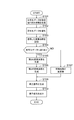
つぎに、この復号装置10の動作について説明する。図3は、復号装置10の動作を示すフローチャートである。まず、通信装置100において、符号化データが受信部7により受信され、誤り検出情報生成部8により誤り検出情報が生成される(S101)。復号装置10では、復号部11により符号化データが復号化される(S102)。そして、バッファ部12に、復号化された変換係数が蓄積される(S103)。なお、S102およびS103の処理は、S104とS107との間で処理するように構成することもできる。これは、受信データのパケットロスなどで符号化データが消失してしまうことを考慮した処理である。
Next, the operation of the
誤り検出情報が符号化データに誤りがあることを示している場合には(S104)、誤りがある符号化データのフレームに隣接する誤りのないフレームの変換係数に基づいて第2の変換係数が第2の変換係数生成部14により生成される(S105)。そして、この第2の変換係数が第2の逆変換部15により逆変換され、修正復号信号が得られる(S106)。そして、この修正復号信号に基づいて生成部19により再生信号が生成され、(S108)、再生信号が通信装置100の再生部9に出力される(S109)。
When the error detection information indicates that there is an error in the encoded data (S104), the second conversion coefficient is determined based on the conversion coefficient of the frame without error adjacent to the frame of the encoded data with error. Generated by the second conversion coefficient generation unit 14 (S105). Then, the second transform coefficient is inversely transformed by the second
また、誤り検出情報が符号化データに誤りがないことを示している場合には(S104)、バッファ部12により蓄積された変換係数が、第1の逆変換部13により逆変換され、通常復号信号が得られる(S107)。そして、この通常復号信号に基づいて生成部19により再生信号が生成され、(S108)、再生信号が出力される(S109)。
If the error detection information indicates that there is no error in the encoded data (S104), the transform coefficient accumulated by the
つぎに、第2の実施形態の復号装置10aについて説明する。図4は、第2の実施形態の復号装置10aのブロック図である。第1の実施形態と同様に、変換規則としてMDCTを例に説明するが、変換方法はこれ以外の方式でもよい。なお、誤り検出情報に誤りがあることが示されていない場合は、第1の実施形態と同様の処理を行うため、その処理の説明は省略する。また、第1の実施形態の復号装置10と同様に通信装置100に適用されるものである。
Next, the
この復号装置10aは、復号部11(復号手段)、バッファ部12、第1の逆変換部13(第1の逆変換手段)、変換係数生成部20、第2の逆変換部15(第2の逆変換手段)、および生成部19(生成手段)を含んで構成されている。また、変換係数生成部20は、第1の変換係数生成部201(第1の変換係数生成手段)および第2の変換係数生成部202(第2の変換係数生成手段)を含んで構成されている。以下、各構成について説明する。
The
復号部11は、符号化方式に応じた所定の規則に基づいて、受信した符号化データを復号して変換係数(通常変換係数)Xcを生成する部分である。この復号部11は、生成した変換係数をバッファ部12に出力する。バッファ部12は、復号部11で復号した変換係数を一時的に蓄積する部分である。
The
変換係数生成部20は、第1の変換係数生成部201と第2の変換係数生成部202とを含んで構成されている。変換係数生成部20は、受信した符号化データに誤りが含まれていることを誤り検出情報が示している場合、バッファ部12に蓄積されている誤りのないフレームの変換係数に基づいて、誤りが含まれていた符号化データに対応するフレームmの変換係数を生成する部分である。具体的には、第1の変換係数生成部201および第2の変換係数生成部202が以下のように処理を行う。
The conversion
第1の変換係数生成部201は、受信した符号化データに誤りが含まれていることを誤り検出情報が示している場合、バッファ部12に記憶されている誤りのないフレームの変換係数に基づいて、誤りが含まれていた符号化データに対応するフレームmの第1の変換係数(第1の修正変換係数)Xc(m,k)を、生成する部分である。例えば、第1の変換係数生成部201は、バッファ部12に記憶されている、誤りのあるフレームの近傍にある(例えば隣接する)フレーム(誤りのないものが好ましい)の変換係数を複写し、または当該フレームの変換係数における雑音置換を行うなど、従来ある手法を用いることにより、第1の変換係数Xc(m,k)生成する。そして、第1の変換係数生成部201は、生成した第1の変換係数を第1の逆変換部13に出力する。なお、便宜上、変換係数と第1の変換係数とは、ともにXcで表すことにする。
When the error detection information indicates that the received encoded data includes an error, the first transform
第2の変換係数生成部202は、受信した符号化データに誤りが含まれていることを誤り検出情報が示している場合、バッファ部12に記憶されている誤りのないフレームの変換係数に基づいて、誤りが含まれていた符号化データに対応するフレームmの第2の変換係数(第2の修正変換係数)Xs(m,k)を、第1の実施形態に示す方法と同様の方法(例えば式(3)に示す方法)により生成する部分である。第2の変換係数生成部202は、生成した第1の変換係数を第2の逆変換部15に出力する。なお、上述第2の変換係数Xsは第1の変換係数Xcと同じ算出方法を使って得るようにしても良い。
When the error detection information indicates that the received encoded data includes an error, the second transform
第1の逆変換部13および第2の逆変換部15は、それぞれ入力した第1の変換係数および第2の変換係数に対して式(1)および式(4)に従った逆変換処理を行う。そして、第1の逆変換部13および第2の逆変換部15は、それぞれ逆変換処理して得た復号信号(第1の修正復号信号、第2の修正復号信号)を生成部19に出力する。
The first
生成部19は、最終的な復号信号を得るため、第1の逆変換部13から出力された逆変換された第1の修正復号信号および第2の逆変換部15から出力された逆変換された第2の修正復号信号を合成して、再生信号を生成する部分である。例えば、生成部19は、第1の逆変換部13から出力された第1の修正復号信号に対しては、式(5)に従った処理を行い、第2の逆変換部15から出力された第2の修正復号信号に対しては、式(6)および(7)に従った処理を行う。そして、生成部19は、生成した再生信号を平均する処理を実行し、平均処理した再生信号を復号音として出力する。
In order to obtain the final decoded signal, the
このように、第2の実施形態においては、第1の変換係数生成部201および第2の変換係数生成部202を用いて、第1の修正復号信号および第2の修正復号信号を出力し、出力したこれら復号信号を平均して復号音として出力することにより、フレーム間における不連続性を軽減した復号音を出力することができる。この第2の実施形態の復号装置10aは、2種類の再生信号を平均して復号音としているため、復号装置10の処理と比較して、より不連続性が軽減した復号音を出力することができる。
Thus, in the second embodiment, using the first transform
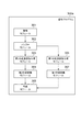
つぎに、この復号装置10aの動作について説明する。図5は、復号装置10aの動作を示すフローチャートである。まず、通信装置100において、受信部7により符号化データが受信され、また誤り検出情報生成部8により誤り検出情報が生成される(S201)。復号装置10aでは、復号部11により符号化データが復号化される(S202)。そして、バッファ部12に、復号化された変換係数が蓄積される(S203)。なお、S202およびS203の処理は、S204とS210との間で処理するように構成することもできる。これは、受信データのパケットロスなどで符号化データが消失してしまうことを考慮した処理である。
Next, the operation of the
誤り検出情報が符号化データに誤りがあることを示している場合には(S204)、誤りがあるフレームに隣接するフレームの変換係数に基づいて第1の変換係数が第1の変換係数生成部201により生成される(S205)。また、誤りがあるフレームの前後に隣接するフレームの変換係数に基づいて第2の変換係数が第2の変換係数生成部202により生成される(S206)。なお、このS205とS206との順番は逆でも良い。
If the error detection information indicates that there is an error in the encoded data (S204), the first transform coefficient is generated based on the transform coefficient of the frame adjacent to the frame having the error. 201 (S205). Also, the second transform
そして、第1の変換係数が第1の逆変換部13により逆変換され、第1の修正復号信号が得られ(S207)、第2の変換係数が第2の逆変換部15により逆変換され、第2の修正復号信号が得られる(S208)。そして、これら第1および第2の修正復号信号に基づいて生成部19により復号信号が合成され再生信号が生成され、(S209)、生成された再生信号が通信装置100の再生部9に出力される(S212)。
Then, the first transform coefficient is inversely transformed by the first
また、誤り検出情報が符号化データに誤りがないことを示している場合には(S204)、バッファ部12により蓄積された変換係数が、第1の逆変換部13により逆変換され、復号信号が得られる(S210)。そして、この復号信号に基づいて生成部19により再生信号が生成され、(S211)、再生信号が出力される(S212)。
When the error detection information indicates that there is no error in the encoded data (S204), the transform coefficient accumulated by the
つぎに、第3の実施形態の復号装置10bについて説明する。図6は、第3の実施形態の復号装置10bのブロック図である。この復号装置10bは、復号部11(復号手段)、バッファ部12、第1の逆変換部13(第1の逆変換手段)、第2の逆変換部15(第2の逆変換手段)、生成部19(生成手段)、変換係数生成部20、および制御部31(選択手段、相関度算出手段)を含んで構成されている。また、変換係数生成部20は、第1の変換係数生成部201(第1の変換係数生成手段)、第2の変換係数生成部202(第2の変換係数生成手段)を含んで構成されている。なお、誤り検出情報に誤りがあることが示されていない場合は、第1の実施形態と同様の処理を行うため、その処理の説明は省略する。また、第1の実施形態の復号装置10と同様に通信装置100に適用されるものである。
Next, the
復号部11は、符号化方式に応じた所定の規則に基づいて、受信した符号化データを復号して変換係数(通常変換係数)を生成する部分である。この復号部11は、生成した変換係数をバッファ部12に出力する。バッファ部12は、復号部11で復号した変換係数を一時的に蓄積する部分である。
The
変換係数生成部20は、第1の変換係数生成部201により生成された第1の変換係数(第1の修正変換係数)または第2の変換係数生成部202により生成された第2の変換係数(第2の修正変換係数)のいずれか一方を制御部31による制御に基づいて選択して第1の逆変換部13または第2の逆変換部15のいずれか一方にのみに出力する部分である。
The conversion
第1の変換係数生成部201は、誤り検出情報が符号化データに誤りがあることを示している場合には、バッファ部12に記憶されているフレーム(誤りのないものが好ましい)の変換係数に基づいて、誤りが含まれていた符号化データに対応するフレームmの第1の変換係数Xc(m,k)を生成する。例えば、第1の変換係数生成部201は、バッファ部12に記憶されているフレームm−1の変換係数を複写し、または当該フレームm−1の変換係数における雑音置換を行うなど、従来ある手法を用いることにより、第1の変換係数Xc(m,k)を生成する。そして、第1の変換係数生成部201は、生成した第1の変換係数を第1の逆変換部13に出力する。
If the error detection information indicates that there is an error in the encoded data, the first transform
第2の変換係数生成部202は、誤り検出情報が符号化データに誤りがあることを示している場合には、バッファ部12に記憶されているフレームm−1の変換係数に基づいて、誤りが含まれていた符号化データに対応するフレームmの第2の変換係数Xs(m,k)を、第1の実施形態に示す方法と同様の方法(例えば式(3)に示す方法)により生成する。第2の変換係数生成部202は、生成した第1の変換係数を第2の逆変換部15に出力する。
When the error detection information indicates that there is an error in the encoded data, the second transform
制御部31は、誤り検出情報が符号化データに誤りがあることを示している場合には、誤りが含まれていた符号化データに対応するフレームmの変換係数を求める時にバッファ部12に記憶されている誤りのない変換係数を用いて、第1の変換係数生成部201から出力される第1の変換係数、または第2の変換係数生成部202から出力される第2の変換係数のいずれか一方の変換係数を選択するための制御情報を生成する。例えば、誤りが発生したフレームmとしたときに、制御部31は、符号化データにおける、m−2番目とm−1番目のフレームの変換係数の相関値を算出する。そして、制御部31は、算出した相関値がある閾値を越えた場合は、第1の変換係数生成部201で生成された第1の変換係数を選択し、算出した相関値が閾値を超えない場合は、第2の変換係数生成部202で生成された第2の変換係数を選択する。
If the error detection information indicates that there is an error in the encoded data, the
制御部31は、第1の変換係数を選択した場合には、第1の変換係数生成部201から第1の逆変換部13に、第1の変換係数を出力するように変換係数生成部20の制御を行う。また、制御部31は、第2の変換係数を選択した場合には、第2の変換係数生成部202から第2の逆変換部15に、第2の変換係数を出力するように変換係数生成部20の制御を行う。
When the first conversion coefficient is selected, the
第1の逆変換部13は、誤り検出情報が符号化データに誤りがあることを示している場合には、第1の変換係数生成部201から出力される第1の変換係数を入力するように動作する。誤り検出情報が符号化データに誤りがないことを示している場合には、バッファ部12に記憶されている変換係数を入力するように動作する。そして、入力した第1の変換係数または変換係数に対して上述の式(1)を用いて逆変換処理を行い、復号信号を得る。第1の逆変換部13は、逆変換して得た復号信号を生成部19に出力する。
When the error detection information indicates that there is an error in the encoded data, the first
また、第2の逆変換部15は、入力された第2の変換係数に対して上述の式(4)を用いて逆変換処理を行い、逆変換した復号信号を生成部19に出力する。
Further, the second
生成部19は、誤り検出情報に基づいて、第1の逆変換部13または第2の逆変換部15から出力された復号信号を入力し、入力した復号信号を上述の式(5)または式(6)および(7)にしたがって処理して再生信号を生成し復号音として出力する。すなわち、生成部19は、誤り検出情報が符号化データに誤りがあることを示している場合は、式(5)に基づいて再生信号の生成処理を行い、誤り検出情報が符号化データに誤りがないことを示している場合には、式(6)および(7)に基づいて再生信号の生成処理を行う。
The
このように、制御部31は、第1の変換係数生成部201で生成された第1の変換係数または第2の変換係数生成部202で生成された第2の変換係数のうち、予め定めた基準値(つまり、フレーム間における相関の度合い)に基づいて、いずれか一方を選択して、生成部19にその逆変換されたデータを出力することにより、フレーム間において不連続性の軽減した再生信号を生成することができる。
As described above, the
すなわち、制御情報(相関値)に基づいて、フレーム間における相関の度合いが大きい場合には、その前のフレーム(フレームm−1)に基づいて生成された変換係数を用いて再生信号の生成を行い、相関の度合いが小さい場合には、そのフレームの前後のフレーム(フレームm−1およびm+1)に基づいて生成された変換係数を用いて再生信号の生成を行うことにより、フレーム間の相関の程度を考慮した変換係数を選択することができ、より適切に不連続性を軽減した復号音を出力することができる。 That is, when the degree of correlation between frames is large based on the control information (correlation value), the reproduction signal is generated using the conversion coefficient generated based on the previous frame (frame m−1). If the degree of correlation is small, the reproduction signal is generated using the transform coefficients generated based on the frames before and after the frame (frames m−1 and m + 1), and thus the correlation between the frames is calculated. A transform coefficient considering the degree can be selected, and a decoded sound in which discontinuity is more appropriately reduced can be output.
つぎに、この第3の実施形態の変形例である第4の実施形態について説明する。図7は、第4の実施形態の複写装置10cのブロック図である。この復号装置10bは、復号部11、バッファ部12、第1の逆変換部13、第2の逆変換部15、生成部19、変換係数生成部20、制御部31、および第2のバッファ部41(記憶手段)を含んで構成されている。また、変換係数生成部20は、第1の変換係数生成部201、第2の変換係数生成部202を含んで構成されている。
Next, a fourth embodiment, which is a modification of the third embodiment, will be described. FIG. 7 is a block diagram of a
この第4の実施形態の復号装置10cは、復号装置10bの制御部31がフレーム間の相関の程度に基づいて、第1の変換係数または第2の変換係数を選択的に決定することに代えて、符号化データのフレームの再生時における電力(パワー)に基づいて第1の変換係数または第2の変換係数を選択的に決定するように構成されている。具体的には、復号装置10cは、復号装置10bの構成に加えて、第2のバッファ部41を備えている。
In the
この第2のバッファ部41は、受信した符号化データの中に含まれている変換係数を選択するための切換情報を記憶する部分である。この切換情報は、復号部11により、受信した符号化データから抽出され第2のバッファ部41に記憶されるものである。なお、この切換情報は、相関値に等価のデータであって、一のフレーム全体の電力(パワー)を量子化した量子化データである。第2のバッファ部41では、出力された切換情報を一時的に蓄積する。
The
制御部31は、第2のバッファ部41に蓄積されている切換情報に基づいて、切換情報が予め定めた閾値を越えた場合には、第1の変換係数生成部201で生成された第1の変換係数を選択し、閾値を超えない場合は、第2の変換係数生成部202で生成された第2の変換係数を選択する。
When the switching information exceeds a predetermined threshold based on the switching information stored in the
このように、第4の実施形態では、切換情報を含んだ符号化データを受信し、受信した符号化データから切換情報を抽出して、変換係数を切り換える制御を行うことができる。 As described above, in the fourth embodiment, it is possible to perform control for receiving the encoded data including the switching information, extracting the switching information from the received encoded data, and switching the conversion coefficient.
さらに、第3の実施形態または第4の実施形態の変形例である第5の実施形態について説明する。図8は、第5の実施形態の復号装置10dのブロック図である。第5の実施形態の復号装置10dは、符号化データおよび誤り検出情報と同時に、第1の変換係数または第2の変換係数を切り換えるための制御情報を受信するものである。
Further, a fifth embodiment which is a modification of the third embodiment or the fourth embodiment will be described. FIG. 8 is a block diagram of a
この復号装置10dに符号化データを送信する符号化装置(図示せず)は、mフレーム目の制御情報をm+1フレーム目の符号化データと多重化して送信する送信手段(図示せず)を備える。
The encoding device (not shown) that transmits the encoded data to the
復号装置10dの変換係数生成部20は、mフレーム目の符号化データに誤りがある場合、m+1フレーム目の制御情報に従って、第1の変換係数生成部201を用いてmフレーム目の変換係数を算出するか、または第2の変換係数生成部202によりmフレーム目の変換係数を算出するかを選択する。そして、変換係数生成部20は、選択した変換係数を第2の逆変換部15に出力する。第2の逆変換部15は、入力された変換係数を逆変換した逆変換データを生成部19に出力する。
When there is an error in the encoded data of the mth frame, the transform
以上の第3の実施形態から第5の実施形態においては、誤りが含まれていた符号化データに対応するフレームmの変換係数を生成する際に、フレーム単位で第1の変換係数と第2の変換係数とのいずれかを選択する構成である。これに対して、第6の実施形態では、フレーム単位に代えて、変換係数をN個の帯域ごとに、第1の変換係数と第2の変換係数とのいずれかを選択する構成をとることもできる。以下、第6の実施形態の復号装置について説明する。第6の実施形態の復号装置は、第3の実施形態の復号装置10bまたは第4の実施形態の復号装置10cと同様の構成として、予め定めた帯域ごとに第1の変換係数または第2の変換係数を選択的に切り換えて第1の逆変換部13または第2の逆変換部15に入力させるものである。この実施形態では復号部11は、符号化データを復号する際には、帯域を区別可能にして復号処理して変換係数を出力している。
In the third to fifth embodiments described above, when generating the transform coefficient of the frame m corresponding to the encoded data including the error, the first transform coefficient and the second transform coefficient are generated in units of frames. The conversion coefficient is selected. On the other hand, in the sixth embodiment, instead of the frame unit, the configuration is such that one of the first transform coefficient and the second transform coefficient is selected for each N bands of transform coefficients. You can also. The decoding device according to the sixth embodiment will be described below. The decoding device according to the sixth embodiment has the same configuration as that of the
受信した符号化データに誤りが含まれていた場合、制御部31は、第1の変換係数生成部201の第1の変換係数、または第2の変換係数生成部202の第2の変換係数のいずれを用いるか、を帯域毎に選択するための制御信号を生成する。帯域毎の制御法の例として、帯域毎の電力を用いる方法を説明する。誤りが発生したフレームmでの帯域iの平均電力を次式により計算する。
![]()
![]()
ここで、bw(i)をi番目の帯域の下限の周波数に対応するkの値とし、bw(0)=0、bw(N)=Mである。なお、bw(i)<=k<bw(i+1)なるkが第i番目の帯域に属することになる。 Here, bw (i) is a value of k corresponding to the lower limit frequency of the i-th band, and bw (0) = 0 and bw (N) = M. Note that k such that bw (i) <= k <bw (i + 1) belongs to the i-th band.
制御部31は、上述の式(9)で求めた平均電力P(m,i)と、予め定めた閾値とを比較し、平均電力P(m,i)が当該閾値以下であれば第i番目の帯域に属する周波数について第1の変換係数生成部201が第1の変換係数を第2の逆変換部15に出力するように制御する。平均電力P(m,i)が予め定めた閾値より大きい場合には、制御部31は、第2の変換係数生成部202が第2の変換係数を第2の逆変換部15に出力するように制御する。
The
第1の逆変換部13および第2の逆変換部15は、それぞれ式(1)または式(4)にしたがって、逆変換処理を行って復号信号を算出する。このとき、生成されなかった周波数kの変換係数の値は0として計算することができる。
The first
つぎに、この復号装置10bの動作について説明する。図9は、復号装置10bの動作を示すフローチャートである。まず、この復号装置10bが備えられた通信装置100において、受信部7により符号化データが受信され、また誤り検出情報生成部8により誤り検出情報が生成される(S301)。復号装置10aでは、復号部11により符号化データが復号化される(S302)。バッファ部12に、分割された変換係数が蓄積される(S303)。なお、S302、およびS303の処理は、S304とS310との間で処理するように構成することもできる。これは、受信データのパケットロスなどで符号化データが消失してしまうことを考慮した処理である。
Next, the operation of the
誤り検出情報が符号化データに誤りがあることを示している場合には(S304)、さらに誤りのあった符号化データのフレームの電力(パワー)が所定値以上であるか否かが判断される(S305)。そして、電力が所定値以上である場合には、誤りがあるフレームに隣接するフレームの変換係数に基づいて第1の変換係数が第1の変換係数生成部201により生成される(S306)。生成された第1の変換係数は、第1の逆変換部13により逆変換されて復号信号が得られる(S307)。得られた第1の修正復号信号に基づいて、生成部19により再生信号が生成され(S311)、再生信号は復号音として出力される(S312)。
If the error detection information indicates that there is an error in the encoded data (S304), it is further determined whether or not the power of the frame of the encoded data having an error is greater than or equal to a predetermined value. (S305). If the power is greater than or equal to the predetermined value, the first transform
また、S305において、誤りのあった符号化データのフレームの電力が所定値以上ではない場合は、誤りがあるフレームの前後に隣接するフレームの変換係数に基づいて第2の変換係数が第2の変換係数生成部202により生成される(S308)。そして、生成された第2の変換係数が第2の逆変換部15により逆変換され、第2の修正復号信号が得られる(S309)。この第2の修正復号信号に基づいて生成部19により再生信号が生成され、(S311)、生成された再生信号が通信装置100の再生部9に出力される(S312)。
In S305, if the power of the frame of the encoded data having an error is not equal to or greater than the predetermined value, the second conversion coefficient is set to the second conversion coefficient based on the conversion coefficients of adjacent frames before and after the frame having an error. It is generated by the conversion coefficient generator 202 (S308). Then, the generated second transform coefficient is inversely transformed by the second
また、誤り検出情報が符号化データに誤りがないことを示している場合には(S304)、バッファ部12により蓄積された変換係数が、第1の逆変換部13により逆変換され、通常復号信号が得られる(S310)。そして、この通常復号信号に基づいて生成部19により再生信号が生成され、(S311)、再生信号が出力される(S312)。
If the error detection information indicates that there is no error in the encoded data (S304), the transform coefficient accumulated by the
なお、第6の実施形態の復号装置の動作としては、S305の処理において帯域ごとに第1の変換係数または第2の変換係数を切り換えるように動作することになる。 Note that the operation of the decoding apparatus according to the sixth embodiment is to operate so as to switch the first transform coefficient or the second transform coefficient for each band in the processing of S305.
このように、第6の実施形態の復号装置の変換係数生成部20は帯域ごとに第1の変換係数、または第2の変換係数を切り替えて第2の逆変換部15に出力するように動作するため、帯域ごとに適切に変換係数を変えて復号音を生成することができ、精度のよい不連続性を軽減した復号信号を得ることができる。
As described above, the transform
つぎに、第2の実施形態〜第5の実施形態の変形例である復号装置10eについて説明する。図10は、復号装置10aの変形例である復号装置10eのブロック図である。この復号装置10eは、それぞれ第1の変換係数生成部201および第2の変換係数生成部202から出力された第1の変換係数(第1の修正変換係数)および第2の変換係数(第2の修正変換係数)を入力して逆変換処理を行う第2の逆変換部61を備える。
Next, a
この第2の逆変換部61は、入力された第1の変換係数および第2の変換係数を式(10)に従って逆変換して修正復号信号を得ることができる。
変換係数生成部20は、第1の変換係数または第2の変換係数を切り換える場合においては、いずれか一方の変換係数のみを第2の逆変換部61に出力することにより、実質的に変換係数の切換制御を行うことができる選択手段として機能する。第2の逆変換部61は、入力された変換係数を、上述式(10)を用いて演算し、復号信号を出力する。このように復号装置10eは第2の逆変換部61を備えることにより、その構成を簡易なものにすることができる。
In the case of switching the first conversion coefficient or the second conversion coefficient, the conversion
上述した本実施形態の復号装置10〜100eは、復号プログラムとして構成することができる。例えば、復号装置10に対応する復号プログラムとして、図11に示したものがあげられる。図11は、復号プログラム300の機能モジュールを示したブロック図である。図11に示すように、復号プログラム300は、復号モジュール301、バッファモジュール302、第2の変換係数生成モジュール303、第2の逆変換モジュール304、生成モジュール305、および第1の逆変換モジュール307を含んで構成されている。
The
この復号プログラム300において、復号モジュール301は、復号部11と同等の機能を有し、バッファモジュール302は、バッファ部12と同等の機能を有し、第2の変換係数生成モジュール303は、第2の変換係数生成部14と同等の機能を有し、第1の逆変換モジュール307は、第1の逆変換部13と同等の機能を有し、第2の逆変換モジュール304は、第2の逆変換部と同等の機能を有し、生成モジュール305は、生成部19と同等の機能を有するように、プログラムされている。
In this
また、復号装置10aに対応する復号プログラムとして、図12に示したものがあげられる。図12は、復号プログラム300aの機能モジュールを示したブロック図である。図12に示すように、復号プログラム300aは、復号モジュール301、バッファモジュール302、第2の変換係数生成モジュール303、第2の逆変換モジュール304、生成モジュール305、第1の変換係数生成モジュール306、および第1の逆変換モジュール307を含んで構成されている。
As a decoding program corresponding to the
この復号プログラム300aにおいて、復号モジュール301は、復号部11と同等の機能を有し、バッファモジュール302は、バッファ部12と同等の機能を有し、第2の変換係数生成モジュール303は、第2の変換係数生成部202と同等の機能を有し、第1の逆変換モジュール307は、第1の逆変換部13と同等の機能を有し、第2の逆変換モジュール304は、第2の逆変換部と同等の機能を有し、生成モジュール305は、生成部19と同等の機能を有し、第1の変換係数生成モジュール306は、第1の変換係数生成部201と同等の機能を有し、第1の逆変換モジュール307は、第1の逆変換部13と同等の機能を有するように、プログラムされている。
In this
また、復号装置10bに対応する復号プログラム300bとして、図13に示したものがあげられる。図13は、復号プログラム300bの機能モジュールを示したブロック図である。図13に示すように、復号プログラム300bは、復号モジュール301、バッファモジュール302、第2の変換係数生成モジュール303、第2の逆変換モジュール304、生成モジュール305、第1の変換係数生成モジュール306、第1の逆変換モジュール307、および制御モジュール308を含んで構成されている。
Further, as the
この復号プログラム300bにおいて、復号モジュール301は、復号部11と同等の機能を有し、バッファモジュール302は、バッファ部12と同等の機能を有し、第2の変換係数生成モジュール303は、第2の変換係数生成部202と同等の機能を有し、第2の逆変換モジュール304は、第2の逆変換部15と同等の機能を有し、生成モジュール305は、生成部19と同等の機能を有し、第1の変換係数生成モジュール306は、第1の変換係数生成部201と同等の機能を有し、第1の逆変換モジュール307は、第1の逆変換部13と同等の機能を有し、制御モジュール308は、制御部31と同等の機能を有するように、プログラムされている。
In the
復号装置10cに対応する復号プログラムとして、第2のバッファ部41と同等の機能を有する第2のバッファモジュール(図示せず)を備えるようにしてもよい。また、復号装置10dに対応する復号プログラムとして、制御モジュール308を搭載することなく、第2の変換係数生成モジュール303または第1の変換係数生成モジュール306に対して符号化装置(図示せず)から出力された制御情報を受信し、その制御情報に基づいた切換動作を行うようにプログラムされてもよい。
As a decoding program corresponding to the
つぎに、本実施形態の復号装置10〜10eの作用・効果について説明する。本実施形態の復号装置10は、復号部11で予め定められたフレーム単位で変換された変換係数が符号化された符号化データを入力し、復号化して通常変換係数を得る。そして、第1の逆変換部13は誤り検出情報が符号化データに誤りがないことを示している場合には、復号された通常変換係数を逆変換して通常復号信号を得る。第2の変換係数生成部14は、符号化データの誤りを示す誤り検出情報が、復号された符号化データに誤りがあることを示している場合には、当該誤りのあるフレームの近傍にあるフレーム(誤りのないものが好ましい)の通常変換係数に基づいて当該誤りのある符号化データに対応するフレームの修正変換係数を算出する。そして、第2の逆変換部15は算出された修正変換係数に対して、隣接するフレームと位相が一致するように逆変換して修正復号信号を得る。生成部19は、符号化データの誤りを示す誤り検出情報が符号化データに誤りがないことを示している場合には、逆変換して得られた通常復号信号に対する再生信号を生成し、誤り検出情報が符号化データに誤りがあることを示している場合に、逆変換されて得られた修正復号信号に対する再生信号を生成することができる。これにより、フレーム間の不連続性が軽減した再生信号を生成することができる。
Next, operations and effects of the
また、復号装置10aは、復号部11で予め定められたフレーム単位で変換された変換係数を符号化した符号化データを入力し、復号化して通常変換係数を得る。第1の変換係数生成部201は、復号化された誤りのあるフレームの近傍にあるフレーム(誤りのないものが好ましい)の通常変換係数を用いて第1の修正変換係数を算出する。また、第2の変換係数生成部202は、誤りのある符号化データの近傍にあるフレーム(誤りのないものが好ましい)を用いて第2の修正変換係数を算出する。第1の逆変換部13は、誤り検出情報が符号化データに誤りがないことを示している場合には、通常変換係数を逆変換して通常復号信号を得て、誤り検出情報が符号化データに誤りがあることを示している場合には、第1の修正変換係数を逆変換して第1の修正復号信号を得る。また、第2の逆変換部15は、第2の修正変換係数を隣接するフレームと位相が一致するように逆変換して第2の修正復号信号を得る。そして、生成部19は、符号化データの誤りを示す誤り検出情報が符号化データに誤りがあることを示している場合には、第1の修正復号信号と第2の修正復号信号とを合成して再生信号を生成し、誤り検出情報が符号化データに誤りがないことを示した場合には、通常復号信号から再生信号を生成することができる。これにより、精度の良いフレーム間の不連続性が軽減した再生信号を生成することができる。
Also, the
また、復号装置10b〜10dは、復号部11で予め定められたフレーム単位で変換された変換係数が符号化された符号化データを入力し、復号化して通常変換係数を得る。第1の変換係数生成部201は、符号化データの誤りを示す誤り検出情報が符号化データに誤りがあることを示している場合には、復号化された誤りのあるフレームの近傍にあるフレーム(誤りのないものが好ましい)の通常変換係数を用いて第1の修正変換係数を算出する。第2の変換係数生成部202は、符号化データの誤りを示す誤り検出情報が符号化データに誤りがあることを示している場合には、復号化された誤りのあるフレームの近傍にあるフレーム(誤りのないものが好ましい)の通常変換係数を用いて第2の修正変換係数を算出する。
Also, the
選択手段として機能する制御部31または変換係数生成部20は、符号化データに誤りがあることを示す誤り検出情報が符号化データに誤りがあることを示している場合には、予め定めた条件に基づいて、第1の修正変換係数、または第2の修正変換係数のいずれか一方のみを出力するように選択する。そして、第1の逆変換部13は、誤り検出情報が符号化データに誤りがないことを示している場合、通常変換係数を逆変換して通常復号信号を得て、誤り検出情報が符号化データに誤りがあることを示している場合であって、第1の修正変換係数を出力するように選択された場合、第1の修正変換係数を逆変換して第1の修正復号信号を得る。また、第2の逆変換部15は、第2の修正変換係数を出力するように選択された場合、第2の修正変換係数を隣接するフレームと位相が一致するように逆変換して第2の修正復号信号を得る。
When the error detection information indicating that there is an error in the encoded data indicates that there is an error in the encoded data, the
そして、生成部19は、誤り検出情報が符号化データに誤りがないことを示している場合、逆変換された通常復号信号に基づいて再生信号を生成し、誤り検出情報が符号化データに誤りがあることを示している場合であって、第1の修正変換係数を出力するように選択された場合、第1の修正復号信号に基づいて再生信号を生成する。また、生成部19は、誤り検出情報が符号化データに誤りがあることを示している場合であって、第2の修正変換係数を出力するように選択された場合、逆変換された第2の修正復号信号に基づいて再生信号を生成することができる。これにより、フレーム間の不連続性が軽減した再生信号を生成することができる。さらに、予め定めた条件に基づいて第1の修正変換係数または第2の修正変換係数のいずれかを選択して修正復号信号を生成するため、よりフレーム間の不連続性が軽減した再生信号を生成することができる。
Then, when the error detection information indicates that there is no error in the encoded data, the
また、これら復号装置10〜10eは、逆修正離散コサイン変換、および逆修正離散サイン変換により逆変換処理を行ってそれぞれ通常復号信号(または第1の修正復号信号)、および修正復号信号(または第2の修正復号信号)を得ることができる。これにより、フレーム間において位相の一致した復号信号を得ることができ、不連続性が軽減した再生信号を生成することができる。
Also, these
また、これら復号装置10〜10eは、生成部19において、誤りのない変換係数を逆変換した通常復号信号と、逆変換した修正復号信号との重複部分において、それぞれ予め定められた窓関数をかけることができる。これにより、フレームが重複している部分においてそのパワーを他のフレームのパワーに応じて適切に調整することができ、他のフレームに応じた適度なパワーの再生信号を得ることができる。
In addition, the
また、復号装置10bは、制御部31において、2つのフレーム同士の相関の度合いを示す相関度に基づいて、第1の修正変換係数、または第2の修正変換係数のいずれか一方のみを出力するように選択することができる。これにより、第1の修正変換係数または第2の修正変換係数のうち適切な修正変換係数を選択することができ、フレーム間の不連続性をより軽減した再生信号を生成することができる。
In addition, the
また、復号装置10cは、第2のバッファ部41において、受信された符号化データから符号化データの電力を抽出して記憶し、制御部31は、第2のバッファ部41に記憶されている符号化データの電力に基づいて、第1の修正変換係数、または第2の修正変換係数のいずれか一方のみを出力するよう選択することができる。これにより、符号化データの電力に従って、第1の修正変換係数または第2の修正変換係数のうち適切な修正変換係数を選択することができ、フレーム間の不連続性をより軽減した再生信号を生成することができる。
Also, the
また、復号装置10dは、符号化データに多重化されて受信された、第1の修正変換係数または第2の修正変換係数のいずれかを選択するための制御情報に基づいて、変換係数生成部20は、第1の修正変換係数、または第2の修正変換係数のいずれか一方のみを出力するように選択することができる。これにより、符号装置側で指定した修正変換係数を選択することができ、第1の修正変換係数または第2の修正変換係数のうち適切な修正変換係数を選択することができ、フレーム間の不連続性をより軽減した再生信号を生成することができる。
In addition, the
また、これら復号装置10から10eは、フレーム単位に第1の修正変換係数または第2の修正変換係数を出力するように選択することができる。
Also, these
また、復号装置10bから10dは、制御部31は、分割された周波数帯域ごとに、第1の修正変換係数、または第2の修正変換係数のいずれか一方のみを出力するように選択することができる。これにより、周波数帯域ごとに第1の修正変換係数または第2の修正変換係数のうち適切な修正変換係数を選択することができ、フレーム間の不連続性をより軽減した再生信号を生成することができる。
In addition, the
1…復号部、2…バッファ部、3…逆変換部、5…変換係数生成部、6…復号装置、7…受信部、8…検出情報生成部、9…再生部、10…復号装置、10a…復号装置、10b…復号装置、10c…復号装置、10d…復号装置、10e…復号装置、11…復号部、12…バッファ部、13…第1の逆変換部、14…第2の変換係数生成部、15…第2の逆変換部、19…生成部、20…変換係数生成部、31…制御部、41…第2のバッファ部、61…第2の逆変換部、100…通信装置、201…変換係数生成部、202…変換係数生成部、300…復号プログラム、300a…復号プログラム、300b…復号プログラム、301…復号モジュール、302…バッファモジュール、303…第2の変換係数生成モジュール、304…第2の逆変換モジュール、305…生成モジュール、306…第1の変換係数生成モジュール、307…第1の逆変換モジュール、308…制御モジュール。
DESCRIPTION OF SYMBOLS 1 ... Decoding part, 2 ... Buffer part, 3 ... Inverse conversion part, 5 ... Conversion coefficient production | generation part, 6 ... Decoding apparatus, 7 ... Reception part, 8 ... Detection information generation part, 9 ... Reproduction part, 10 ... Decoding apparatus, DESCRIPTION OF
Claims (13)
符号化データの誤りを示す誤り検出情報が符号化データに誤りがないことを示している場合には、前記復号手段により復号された通常変換係数を逆変換して通常復号信号を得る第1の逆変換手段と、
符号化データの誤りを示す誤り検出情報が符号化データに誤りがあることを示している場合には、前記復号手段により復号された誤りのあるフレームの近傍にあるフレームの通常変換係数に基づいて当該誤りのある符号化データに対応するフレームの修正変換係数を算出する変換係数算出手段と、
前記変換係数算出手段により算出された修正変換係数に対して、隣接するフレームと位相が一致するように逆変換して修正復号信号を得る第2の逆変換手段と、
符号化データの誤りを示す誤り検出情報が符号化データに誤りがないことを示している場合には、前記第1の逆変換手段により逆変換して得られた通常復号信号に対する再生信号を生成し、前記誤り検出情報が符号化データに誤りがあることを示している場合に、前記第2の逆変換手段により逆変換されて得られた修正復号信号に対する再生信号を生成する生成手段と、
を備える復号装置。 Decoding means for inputting encoded data obtained by encoding a transform coefficient converted in units of a predetermined frame and decoding to obtain a normal transform coefficient;
When the error detection information indicating an error in the encoded data indicates that the encoded data has no error, a first decoded signal is obtained by inversely converting the normal transform coefficient decoded by the decoding means. Inverse transformation means;
If the error detection information indicating the error of the encoded data indicates that the encoded data has an error, the error detection information is based on the normal transform coefficient of the frame in the vicinity of the erroneous frame decoded by the decoding means. Transform coefficient calculating means for calculating a corrected transform coefficient of a frame corresponding to the encoded data having the error;
Second inverse transforming means for obtaining a modified decoded signal by inversely transforming the modified transform coefficient calculated by the transform coefficient calculating means so as to match the phase of an adjacent frame;
When the error detection information indicating an error in the encoded data indicates that the encoded data has no error, a reproduction signal is generated for the normal decoded signal obtained by inverse conversion by the first inverse conversion means. And, when the error detection information indicates that there is an error in the encoded data, generation means for generating a reproduction signal for the modified decoded signal obtained by inverse conversion by the second inverse conversion means,
A decoding device comprising:
符号化データの誤りを示す誤り検出情報が符号化データに誤りがあることを示している場合には、前記復号手段により復号された誤りのあるフレームの近傍にあるフレームの通常変換係数を用いて第1の修正変換係数を算出する第1の変換係数算出手段と、
前記誤り検出情報が符号化データに誤りがあることを示している場合には、前記復号手段により復号された誤りのあるフレームの近傍にあるフレームの通常変換係数を用いて第2の修正変換係数を算出する第2の変換係数算出手段と、
前記誤り検出情報が符号化データに誤りがないことを示している場合には、前記復号手段から出力された変換係数を逆変換して通常復号信号を得て、誤り検出情報が符号化データに誤りがあることを示している場合には、前記第1の変換係数算出手段により算出された第1の修正変換係数を逆変換して第1の修正復号信号を得る第1の逆変換手段と、
前記第2の変換係数算出手段により算出された第2の修正変換係数を隣接するフレームと位相が一致するように逆変換して第2の修正復号信号を得る第2の逆変換手段と、
前記誤り検出情報が符号化データに誤りがあることを示している場合には、前記第1の逆変換手段により逆変換された第1の修正復号信号と前記第2の逆変換手段により逆変換された第2の修正復号信号とを合成して再生信号を生成し、前記誤り検出情報が符号化データに誤りがないことを示した場合には、前記第1の逆変換手段により逆変換された通常復号信号から再生信号を生成する生成手段と、
を備える復号装置。 Decoding means for inputting encoded data obtained by encoding a transform coefficient converted in units of a predetermined frame and decoding to obtain a normal transform coefficient;
When the error detection information indicating the error of the encoded data indicates that the encoded data has an error, the normal conversion coefficient of the frame in the vicinity of the erroneous frame decoded by the decoding unit is used. First conversion coefficient calculation means for calculating a first modified conversion coefficient;
If the error detection information indicates that there is an error in the encoded data, a second modified transform coefficient is used by using a normal transform coefficient of a frame in the vicinity of the erroneous frame decoded by the decoding means. Second conversion coefficient calculation means for calculating
When the error detection information indicates that there is no error in the encoded data, the transform coefficient output from the decoding means is inversely converted to obtain a normal decoded signal, and the error detection information is converted into the encoded data. If there is an error, first inverse transform means for inversely transforming the first modified transform coefficient calculated by the first transform coefficient computing means to obtain a first modified decoded signal; ,
A second inverse transform unit that inversely transforms the second modified transform coefficient calculated by the second transform coefficient calculation unit so as to match the phase of an adjacent frame to obtain a second modified decoded signal;
If the error detection information indicates that there is an error in the encoded data, the first modified decoded signal inversely transformed by the first inverse transform means and the inverse transform by the second inverse transform means When the error detection information indicates that there is no error in the encoded data, it is inversely transformed by the first inverse transform means. Generating means for generating a reproduction signal from the normal decoded signal;
A decoding device comprising:
符号化データの誤りを示す誤り検出情報が符号化データに誤りがあることを示している場合には、前記復号手段により復号化された誤りのあるフレームの近傍にあるフレームの通常変換係数を用いて第1の修正変換係数を算出する第1の変換係数算出手段と、
符号化データの誤りを示す誤り検出情報が符号化データに誤りがあることを示している場合には、前記復号手段により復号化された誤りのあるフレームの近傍にあるフレームの通常変換係数を用いて第2の修正変換係数を算出する第2の変換係数算出手段と、
符号化データに誤りがあることを示す誤り検出情報が符号化データに誤りがあることを示している場合には、予め定めた条件に基づいて、前記第1の変換係数生成手段により算出される第1の修正変換係数、または前記第2の変換係数生成手段により算出される第2の修正変換係数のいずれか一方のみを出力するように選択する選択手段と、
前記誤り検出情報が符号化データに誤りがないことを示している場合、前記復号手段から出力された通常変換係数を逆変換して通常復号信号を得て、前記誤り検出情報が符号化データに誤りがあることを示している場合であって、前記選択手段により第1の修正変換係数を出力するように選択された場合、前記第1の変換係数算出手段により算出された第1の修正変換係数を逆変換して第1の修正復号信号を得る第1の逆変換手段と、
前記選択手段により第2の修正変換係数を出力するように選択された場合、前記第2の変換係数算出手段により算出された第2の修正変換係数を隣接するフレームと位相が一致するように逆変換して第2の修正復号信号を得る第2の逆変換手段と、
誤り検出情報が符号化データに誤りがないことを示している場合、前記第1の逆変換手段により逆変換された通常復号信号に基づいて再生信号を生成し、誤り検出情報が符号化データに誤りがあることを示している場合であって、前記選択手段により第1の修正変換係数を出力するように選択された場合、第1の修正復号信号に基づいて再生信号を生成し、誤り検出情報が符号化データに誤りがあることを示している場合であって、前記選択手段により第2の修正変換係数を出力するように選択された場合、前記第2の逆変換手段により逆変換された第2の修正復号信号に基づいて再生信号を生成する生成手段と、
を備える復号装置。 Decoding means for inputting encoded data obtained by encoding a transform coefficient converted in units of a predetermined frame and decoding to obtain a normal transform coefficient;
When the error detection information indicating the error of the encoded data indicates that the encoded data has an error, the normal transform coefficient of the frame in the vicinity of the erroneous frame decoded by the decoding means is used. First conversion coefficient calculating means for calculating the first corrected conversion coefficient;
When the error detection information indicating the error of the encoded data indicates that the encoded data has an error, the normal transform coefficient of the frame in the vicinity of the erroneous frame decoded by the decoding means is used. Second conversion coefficient calculation means for calculating the second modified conversion coefficient;
If the error detection information indicating that there is an error in the encoded data indicates that there is an error in the encoded data, it is calculated by the first transform coefficient generating means based on a predetermined condition. Selecting means for selecting to output only one of the first corrected conversion coefficient or the second corrected conversion coefficient calculated by the second conversion coefficient generating means;
When the error detection information indicates that there is no error in the encoded data, the normal transform coefficient output from the decoding means is inversely converted to obtain a normal decoded signal, and the error detection information is converted into the encoded data. If it is indicated that there is an error and the selection means selects to output the first corrected conversion coefficient, the first correction conversion calculated by the first conversion coefficient calculation means First inverse transform means for inversely transforming coefficients to obtain a first modified decoded signal;
When the selection unit selects to output the second modified transform coefficient, the second modified transform coefficient calculated by the second transform coefficient calculation unit is reversed so that the phase of the second modified transform coefficient matches the adjacent frame. Second inverse transform means for transforming to obtain a second modified decoded signal;
When the error detection information indicates that there is no error in the encoded data, a reproduction signal is generated based on the normal decoded signal inversely converted by the first inverse conversion means, and the error detection information is converted into the encoded data. If it indicates that there is an error and the selection means selects to output the first modified transform coefficient, a reproduced signal is generated based on the first modified decoded signal, and error detection is performed. If the information indicates that there is an error in the encoded data and the selection means selects to output the second modified conversion coefficient, the information is inversely converted by the second inverse conversion means. Generating means for generating a reproduction signal based on the second modified decoded signal;
A decoding device comprising:
前記選択手段は、前記相関度算出手段により算出された相関度に基づいて、前記第1の変換係数生成手段から出力される第1の修正変換係数、または前記第2の変換係数生成手段から出力される第2の修正変換係数のいずれか一方のみを出力するように選択することを特徴とする請求項3に記載の復号装置。 Correlation degree calculating means for calculating a correlation degree indicating a degree of correlation between two frames in the vicinity of code data having an error, and
The selection means outputs from the first modified conversion coefficient output from the first conversion coefficient generation means or from the second conversion coefficient generation means based on the correlation degree calculated by the correlation degree calculation means. 4. The decoding apparatus according to claim 3, wherein only one of the second modified transform coefficients to be output is selected to be output.
前記選択手段は、前記記憶手段に記憶されている符号化データの電力に基づいて、前記第1の変換係数生成手段から出力される第1の修正変換係数、または前記第2の変換係数生成手段から出力される第2の修正変換係数のいずれか一方のみを出力するように選択することを特徴とする請求項3に記載の復号装置。 Storage means for extracting and storing the power of the encoded data from the encoded data received by the receiving means;
The selection unit is configured to output the first modified transform coefficient output from the first transform coefficient generation unit or the second transform coefficient generation unit based on the power of the encoded data stored in the storage unit. 4. The decoding device according to claim 3, wherein only one of the second modified transform coefficients output from is selected to be output.
9. The decoding device according to claim 3 , wherein the selection unit selects so as to output the first modified transform coefficient or the second modified transform coefficient in frame units. .
符号化データの誤りを示す誤り検出情報が符号化データに誤りがないことを示している場合には、前記復号ステップにより復号された通常変換係数を逆変換して通常復号信号を得る第1の逆変換ステップと、
符号化データの誤りを示す誤り検出情報が符号化データに誤りがあることを示している場合には、前記復号ステップにより復号された誤りのあるフレームの近傍にあるフレームの通常変換係数に基づいて当該誤りのある符号化データに対応するフレームの修正変換係数を算出する変換係数算出ステップと、
前記変換係数算出ステップにより算出された修正変換係数に対して、隣接するフレームと位相が一致するように逆変換して修正復号信号を得る第2の逆変換ステップと、
符号化データの誤りを示す誤り検出情報が符号化データに誤りがないことを示している場合には、前記第1の逆変換ステップにより逆変換して得られた通常復号信号に対する再生信号を生成し、前記誤り検出情報が符号化データに誤りがあることを示している場合に、前記第2の逆変換ステップにより逆変換されて得られた修正復号信号に対する再生信号を生成する生成ステップと、
を備える復号方法。 A decoding step in which encoded data obtained by encoding a transform coefficient that has been converted in units of a predetermined frame is input and decoded to obtain a normal transform coefficient;
When error detection information indicating an error in the encoded data indicates that there is no error in the encoded data, a first decoded signal is obtained by inversely converting the normal transform coefficient decoded in the decoding step. An inverse transformation step;
When the error detection information indicating the error of the encoded data indicates that the encoded data has an error, the error detection information is based on the normal transform coefficient of the frame in the vicinity of the erroneous frame decoded by the decoding step. A transform coefficient calculating step for calculating a modified transform coefficient of a frame corresponding to the encoded data having the error;
A second inverse transform step for obtaining a modified decoded signal by performing inverse transform on the modified transform coefficient calculated by the transform coefficient calculating step so that the phase of the modified transform coefficient matches with an adjacent frame;
If the error detection information indicating an error in the encoded data indicates that there is no error in the encoded data, a reproduction signal is generated for the normal decoded signal obtained by inverse conversion in the first inverse conversion step. And, when the error detection information indicates that there is an error in the encoded data, a generation step of generating a reproduction signal for the modified decoded signal obtained by inverse conversion by the second inverse conversion step;
A decoding method comprising:
符号化データの誤りを示す誤り検出情報が符号化データに誤りがあることを示している場合には、前記復号ステップにより復号された誤りのあるフレームの近傍にあるフレームの通常変換係数を用いて第1の修正変換係数を算出する第1の変換係数算出ステップと、
前記誤り検出情報が符号化データに誤りがあることを示している場合には、前記復号ステップにより復号された誤りのあるフレームの近傍にあるフレームの通常変換係数を用いて第2の修正変換係数を算出する第2の変換係数算出ステップと、
前記誤り検出情報が符号化データに誤りがないことを示している場合には、前記復号ステップから出力された変換係数を逆変換して通常復号信号を得て、誤り検出情報が符号化データに誤りがあることを示している場合には、前記第1の変換係数算出ステップにより算出された第1の修正変換係数を逆変換して第1の修正復号信号を得る第1の逆変換ステップと、
前記第2の変換係数算出ステップにより算出された第2の修正変換係数を隣接するフレームと位相が一致するように逆変換して第2の修正復号信号を得る第2の逆変換ステップと、
前記誤り検出情報が符号化データに誤りがあることを示している場合には、前記第1の逆変換ステップにより逆変換された第1の修正復号信号と前記第2の逆変換ステップにより逆変換された第2の修正復号信号とを合成して再生信号を生成し、前記誤り検出情報が符号化データに誤りがないことを示した場合には、前記第1の逆変換ステップにより逆変換された通常復号信号から再生信号を生成する生成ステップと、
を備える復号方法。 A decoding step in which encoded data obtained by encoding a transform coefficient that has been converted in units of a predetermined frame is input and decoded to obtain a normal transform coefficient;
When the error detection information indicating the error of the encoded data indicates that the encoded data has an error, the normal transform coefficient of the frame in the vicinity of the erroneous frame decoded by the decoding step is used. A first conversion coefficient calculation step of calculating a first modified conversion coefficient;
If the error detection information indicates that there is an error in the encoded data, a second corrected transform coefficient is used by using a normal transform coefficient of a frame in the vicinity of the erroneous frame decoded by the decoding step. A second conversion coefficient calculating step for calculating
When the error detection information indicates that there is no error in the encoded data, the transform coefficient output from the decoding step is inversely converted to obtain a normal decoded signal, and the error detection information is converted into the encoded data. If there is an error, a first inverse transform step of inversely transforming the first modified transform coefficient calculated by the first transform coefficient calculating step to obtain a first modified decoded signal; ,
A second inverse transform step for obtaining a second modified decoded signal by inversely transforming the second modified transform coefficient calculated by the second transform coefficient calculating step so that the phase thereof matches that of an adjacent frame;
When the error detection information indicates that there is an error in the encoded data, the first modified decoded signal inversely transformed by the first inverse transformation step and the inverse transformation by the second inverse transformation step When the error detection information indicates that there is no error in the encoded data, it is inversely transformed by the first inverse transformation step. Generating a reproduction signal from the normal decoded signal;
A decoding method comprising:
符号化データの誤りを示す誤り検出情報が符号化データに誤りがあることを示している場合には、前記復号ステップにより復号化された誤りのあるフレームの近傍にあるフレームの通常変換係数を用いて第1の修正変換係数を算出する第1の変換係数算出ステップと、
符号化データの誤りを示す誤り検出情報が符号化データに誤りがあることを示している場合には、前記復号ステップにより復号化された誤りのあるフレームの近傍にあるフレームの通常変換係数を用いて第2の修正変換係数を算出する第2の変換係数算出ステップと、
符号化データに誤りがあることを示す誤り検出情報が符号化データに誤りがあることを示している場合には、予め定めた条件に基づいて、前記第1の変換係数生成ステップにより算出される第1の修正変換係数、または前記第2の変換係数生成ステップにより算出される第2の修正変換係数のいずれか一方のみを出力するように選択する選択ステップと、
前記誤り検出情報が符号化データに誤りがないことを示している場合、前記復号ステップから出力された通常変換係数を逆変換して通常復号信号を得て、前記誤り検出情報が符号化データに誤りがあることを示している場合であって、前記選択ステップにより第1の修正変換係数を出力するように選択された場合、前記第1の変換係数算出ステップにより算出された第1の修正変換係数を逆変換して第1の修正復号信号を得る第1の逆変換ステップと、
前記選択ステップにより第2の修正変換係数を出力するように選択された場合、前記第2の変換係数算出ステップにより算出された第2の修正変換係数を隣接するフレームと位相が一致するように逆変換して第2の修正復号信号を得る第2の逆変換ステップと、
誤り検出情報が符号化データに誤りがないことを示している場合、前記第1の逆変換ステップにより逆変換された通常復号信号に基づいて再生信号を生成し、誤り検出情報が符号化データに誤りがあることを示している場合であって、前記選択ステップにより第1の修正変換係数を出力するように選択された場合、第1の修正復号信号に基づいて再生信号を生成し、誤り検出情報が符号化データに誤りがあることを示している場合であって、前記選択ステップにより第2の修正変換係数を出力するように選択された場合、前記第2の逆変換ステップにより逆変換された第2の修正復号信号に基づいて再生信号を生成する生成ステップと、を備える復号方法。
A decoding step in which encoded data obtained by encoding a transform coefficient that has been converted in units of a predetermined frame is input and decoded to obtain a normal transform coefficient;
When the error detection information indicating the error of the encoded data indicates that there is an error in the encoded data using the normal conversion coefficient of the frame in the vicinity of the frame having an error which is decoded by said decoding step A first conversion coefficient calculating step for calculating a first corrected conversion coefficient;
When the error detection information indicating the error of the encoded data indicates that there is an error in the encoded data using the normal conversion coefficient of the frame in the vicinity of the frame having an error which is decoded by said decoding step A second conversion coefficient calculating step for calculating a second corrected conversion coefficient;
When the error detection information indicating that there is an error in the encoded data indicates that there is an error in the encoded data, it is calculated by the first transform coefficient generation step based on a predetermined condition. A selection step of selecting to output only one of the first corrected conversion coefficient or the second corrected conversion coefficient calculated by the second conversion coefficient generation step;
When the error detection information indicates that there is no error in the encoded data, the normal transform coefficient output from the decoding step is inversely converted to obtain a normal decoded signal, and the error detection information is converted into the encoded data. If it is indicated that there is an error, and the selection step selects to output the first corrected conversion coefficient, the first correction conversion calculated by the first conversion coefficient calculation step A first inverse transform step for inversely transforming the coefficients to obtain a first modified decoded signal;
If the second modified transform coefficient is selected to be output by the selection step, the second modified transform coefficient calculated by the second transform coefficient calculation step is reversed so that the phase of the second modified transform coefficient matches the adjacent frame. A second inverse transform step for transforming to obtain a second modified decoded signal;
When the error detection information indicates that there is no error in the encoded data, a reproduction signal is generated based on the normal decoded signal inversely converted by the first inverse conversion step, and the error detection information is converted into the encoded data. If it indicates that there is an error and the selection step selects to output the first modified transform coefficient, a reproduction signal is generated based on the first modified decoded signal, and error detection is performed. If the information indicates that there is an error in the encoded data, and if the selection step outputs the second modified transform coefficient, the information is inversely transformed by the second inverse transformation step. And a generation step of generating a reproduction signal based on the second modified decoded signal.
Priority Applications (1)
| Application Number | Priority Date | Filing Date | Title |
|---|---|---|---|
| JP2005232484A JP4536621B2 (en) | 2005-08-10 | 2005-08-10 | Decoding device and decoding method |
Applications Claiming Priority (1)
| Application Number | Priority Date | Filing Date | Title |
|---|---|---|---|
| JP2005232484A JP4536621B2 (en) | 2005-08-10 | 2005-08-10 | Decoding device and decoding method |
Publications (2)
| Publication Number | Publication Date |
|---|---|
| JP2007049491A JP2007049491A (en) | 2007-02-22 |
| JP4536621B2 true JP4536621B2 (en) | 2010-09-01 |
Family
ID=37851953
Family Applications (1)
| Application Number | Title | Priority Date | Filing Date |
|---|---|---|---|
| JP2005232484A Expired - Fee Related JP4536621B2 (en) | 2005-08-10 | 2005-08-10 | Decoding device and decoding method |
Country Status (1)
| Country | Link |
|---|---|
| JP (1) | JP4536621B2 (en) |
Families Citing this family (4)
| Publication number | Priority date | Publication date | Assignee | Title |
|---|---|---|---|---|
| JP5302190B2 (en) * | 2007-05-24 | 2013-10-02 | パナソニック株式会社 | Audio decoding apparatus, audio decoding method, program, and integrated circuit |
| CN101958119B (en) * | 2009-07-16 | 2012-02-29 | 中兴通讯股份有限公司 | Audio-frequency drop-frame compensator and compensation method for modified discrete cosine transform domain |
| US8428959B2 (en) * | 2010-01-29 | 2013-04-23 | Polycom, Inc. | Audio packet loss concealment by transform interpolation |
| BR112015031178B1 (en) | 2013-06-21 | 2022-03-22 | Fraunhofer-Gesellschaft zur Förderung der angewandten Forschung e.V | Apparatus and method for generating an adaptive spectral shape of comfort noise |
Citations (3)
| Publication number | Priority date | Publication date | Assignee | Title |
|---|---|---|---|---|
| JPH0884334A (en) * | 1994-09-14 | 1996-03-26 | Hitachi Ltd | Decoding method for image signal and its device |
| JP2003520459A (en) * | 1998-08-20 | 2003-07-02 | サーノフ コーポレイション | Error concealment for hierarchical subband coding and decoding |
| JP2007514977A (en) * | 2003-12-19 | 2007-06-07 | テレフオンアクチーボラゲット エル エム エリクソン(パブル) | Improved error concealment technique in the frequency domain |
-
2005
- 2005-08-10 JP JP2005232484A patent/JP4536621B2/en not_active Expired - Fee Related
Patent Citations (3)
| Publication number | Priority date | Publication date | Assignee | Title |
|---|---|---|---|---|
| JPH0884334A (en) * | 1994-09-14 | 1996-03-26 | Hitachi Ltd | Decoding method for image signal and its device |
| JP2003520459A (en) * | 1998-08-20 | 2003-07-02 | サーノフ コーポレイション | Error concealment for hierarchical subband coding and decoding |
| JP2007514977A (en) * | 2003-12-19 | 2007-06-07 | テレフオンアクチーボラゲット エル エム エリクソン(パブル) | Improved error concealment technique in the frequency domain |
Also Published As
| Publication number | Publication date |
|---|---|
| JP2007049491A (en) | 2007-02-22 |
Similar Documents
| Publication | Publication Date | Title |
|---|---|---|
| US9355645B2 (en) | Method and apparatus for encoding/decoding stereo audio | |
| KR101586317B1 (en) | A method and an apparatus for processing a signal | |
| JP5267362B2 (en) | Audio encoding apparatus, audio encoding method, audio encoding computer program, and video transmission apparatus | |
| JP5100124B2 (en) | Speech coding apparatus and speech coding method | |
| JP4347698B2 (en) | Parametric audio coding | |
| US20090228284A1 (en) | Method and apparatus for encoding/decoding multi-channel audio signal by using a plurality of variable length code tables | |
| JP5326465B2 (en) | Audio decoding method, apparatus, and program | |
| JP2008261904A (en) | Encoding device, decoding device, encoding method and decoding method | |
| JP5123516B2 (en) | Decoding device, encoding device, decoding method, and encoding method | |
| JP2009533716A (en) | Excitation processing in audio encoding and decoding | |
| JP2009543115A (en) | Apparatus and method for recovering multi-channel audio signal using HE-AAC decoder and MPEG surround decoder | |
| KR20060135699A (en) | Signal decoding apparatus and signal decoding method | |
| JP4536621B2 (en) | Decoding device and decoding method | |
| JP2008033269A (en) | Digital signal processing device, digital signal processing method, and reproduction device of digital signal | |
| EP2264698A1 (en) | Stereo signal converter, stereo signal reverse converter, and methods for both | |
| JP5309944B2 (en) | Audio decoding apparatus, method, and program | |
| US7099823B2 (en) | Coded voice signal format converting apparatus | |
| JP2004184975A (en) | Audio decoding method and apparatus for reconstructing high-frequency component with less computation | |
| EP4143825A2 (en) | Method, apparatus and system for enhancing multi-channel audio in a dynamic range reduced domain | |
| JP2008164823A (en) | Audio data processor | |
| JP2006003580A (en) | Device and method for coding audio signal | |
| JP5340378B2 (en) | Channel signal generation device, acoustic signal encoding device, acoustic signal decoding device, acoustic signal encoding method, and acoustic signal decoding method | |
| JP4065383B2 (en) | Audio signal transmitting apparatus, audio signal receiving apparatus, and audio signal transmission system | |
| JP4195598B2 (en) | Encoding method, decoding method, encoding device, decoding device, encoding program, decoding program | |
| JP2008033211A (en) | Additional signal generation device, restoration device of signal converted signal, additional signal generation method, restoration method of signal converted signal, and additional signal generation program |
Legal Events
| Date | Code | Title | Description |
|---|---|---|---|
| A621 | Written request for application examination |
Free format text: JAPANESE INTERMEDIATE CODE: A621 Effective date: 20080312 |
|
| A977 | Report on retrieval |
Free format text: JAPANESE INTERMEDIATE CODE: A971007 Effective date: 20100326 |
|
| A131 | Notification of reasons for refusal |
Free format text: JAPANESE INTERMEDIATE CODE: A131 Effective date: 20100330 |
|
| A521 | Request for written amendment filed |
Free format text: JAPANESE INTERMEDIATE CODE: A523 Effective date: 20100525 |
|
| TRDD | Decision of grant or rejection written | ||
| A01 | Written decision to grant a patent or to grant a registration (utility model) |
Free format text: JAPANESE INTERMEDIATE CODE: A01 Effective date: 20100615 |
|
| A01 | Written decision to grant a patent or to grant a registration (utility model) |
Free format text: JAPANESE INTERMEDIATE CODE: A01 |
|
| A61 | First payment of annual fees (during grant procedure) |
Free format text: JAPANESE INTERMEDIATE CODE: A61 Effective date: 20100616 |
|
| FPAY | Renewal fee payment (event date is renewal date of database) |
Free format text: PAYMENT UNTIL: 20130625 Year of fee payment: 3 |
|
| R150 | Certificate of patent or registration of utility model |
Ref document number: 4536621 Country of ref document: JP Free format text: JAPANESE INTERMEDIATE CODE: R150 Free format text: JAPANESE INTERMEDIATE CODE: R150 |
|
| R250 | Receipt of annual fees |
Free format text: JAPANESE INTERMEDIATE CODE: R250 |
|
| R250 | Receipt of annual fees |
Free format text: JAPANESE INTERMEDIATE CODE: R250 |
|
| R250 | Receipt of annual fees |
Free format text: JAPANESE INTERMEDIATE CODE: R250 |
|
| R250 | Receipt of annual fees |
Free format text: JAPANESE INTERMEDIATE CODE: R250 |
|
| R250 | Receipt of annual fees |
Free format text: JAPANESE INTERMEDIATE CODE: R250 |
|
| R250 | Receipt of annual fees |
Free format text: JAPANESE INTERMEDIATE CODE: R250 |
|
| LAPS | Cancellation because of no payment of annual fees |