JP4516217B2 - Polarization scattering spectroscopy of tissue - Google Patents
Polarization scattering spectroscopy of tissue Download PDFInfo
- Publication number
- JP4516217B2 JP4516217B2 JP2000594380A JP2000594380A JP4516217B2 JP 4516217 B2 JP4516217 B2 JP 4516217B2 JP 2000594380 A JP2000594380 A JP 2000594380A JP 2000594380 A JP2000594380 A JP 2000594380A JP 4516217 B2 JP4516217 B2 JP 4516217B2
- Authority
- JP
- Japan
- Prior art keywords
- tissue
- light
- probe
- optical fiber
- probe according
- Prior art date
- Legal status (The legal status is an assumption and is not a legal conclusion. Google has not performed a legal analysis and makes no representation as to the accuracy of the status listed.)
- Expired - Fee Related
Links
Images


Classifications
-
- A—HUMAN NECESSITIES
- A61—MEDICAL OR VETERINARY SCIENCE; HYGIENE
- A61B—DIAGNOSIS; SURGERY; IDENTIFICATION
- A61B5/00—Measuring for diagnostic purposes; Identification of persons
- A61B5/0059—Measuring for diagnostic purposes; Identification of persons using light, e.g. diagnosis by transillumination, diascopy, fluorescence
- A61B5/0082—Measuring for diagnostic purposes; Identification of persons using light, e.g. diagnosis by transillumination, diascopy, fluorescence adapted for particular medical purposes
- A61B5/0084—Measuring for diagnostic purposes; Identification of persons using light, e.g. diagnosis by transillumination, diascopy, fluorescence adapted for particular medical purposes for introduction into the body, e.g. by catheters
-
- A—HUMAN NECESSITIES
- A61—MEDICAL OR VETERINARY SCIENCE; HYGIENE
- A61B—DIAGNOSIS; SURGERY; IDENTIFICATION
- A61B5/00—Measuring for diagnostic purposes; Identification of persons
- A61B5/0059—Measuring for diagnostic purposes; Identification of persons using light, e.g. diagnosis by transillumination, diascopy, fluorescence
- A61B5/0075—Measuring for diagnostic purposes; Identification of persons using light, e.g. diagnosis by transillumination, diascopy, fluorescence by spectroscopy, i.e. measuring spectra, e.g. Raman spectroscopy, infrared absorption spectroscopy
Description
【0001】
【関連出願】
本出願はその全内容が引用によりここに組み入れられる1999年1月25日出願の米国出願第09/237,153号の優先権を主張する。
【0002】
【政府の助成】
本発明は、全て又は1部について、アメリカ国立衛生研究所(National Institute for Health)の交付番号(grant number)第P41RR02954号により助成された。米国政府は該発明の一定の権利(certain rights)を有する。
【0003】
【発明の背景】
癌の病変の90%より多くは器官の上皮に関する。結腸直腸(colorectal)、食道(esophageal)、膀胱(bladder)、頚管(cervical)及び喉頭(oral)癌の様な上皮癌の最も共通した形式の幾つかは形成異常(dysplasia)と呼ばれる、良く規定された、検出可能な前癌段階を有する。形成異常は規定された腫瘍遺伝子及び腫瘍抑制遺伝子の突然変異のシーケンシャルな累積により特徴付けられる。もし検出されれば、該形成異常の病変の絶対多数は治る。上皮癌のこの前癌段階の検出と治療への臨床的努力は死亡率を減じることを示して来た。
【0004】
上皮形成異常の診断は、それが典型的にポリープの様な巨視的構造を形成せず、癌が展開した後でのみ視認可能になるのが通常であるために、困難な儘である。上皮形成異常を検出する標準的方法はランダムな生検と該着色した生検材料の病理学的検査に基づいている。しかしながら、ランダムな生検は高いサンプリング誤差を有する。多くの場合、形成異常に対する危険では該上皮表面の1%より少ししか検査されない。
【0005】
全ての種類の上皮形成異常は幾つかの共通の特性、すなわち細胞質比への核の増加、核高色素症、そして増加した数を伴う上皮細胞核の拡大そして上皮細胞の成層化、を有する。これらの良く特徴付けられた上皮変化にも拘わらず、分類することは、経験のある病理学者間でも、高い観察者間不一致で示される様に、難しい儘経過している。
【0006】
【発明の概要】
上皮の形成異常を検出する非侵襲性で、生体内の方法は上皮表面の監視と、人間の前癌条件の病理学的診断を提供する。
【0007】
光学的技術は、それらが非侵襲性で、組織除去を要せず、生体内で行えるので、ランダムな生検の置き換えとなるよう良く適合している。更に、それらは速く(実時間で適用出来る)、比較的高価でなく、微視的規模で作動出来て、かくして非常に小さな形成異常なサイトを見出せる。後者はランダムな生検では非常にミスされ易いものである。
【0008】
本発明は、組織の様な濁った媒体の表面層内の散乱体(scatterer)に関する情報を提供するための偏光の光散乱分光検査法(light scattering spectroscopy)に関する。この過程は蛍光又は吸収スペクトルの特徴を利用する必要はなく、むしろ上皮層の様な表面組織の散乱特性を利用する。それは人間の上皮の大きな散乱体(細胞核)の特性を特徴付け出来て、人間の組織の経時的情報を提供し、生体内で人間器官の形成異常を実時間で診断する。
【0009】
上皮組織の特徴を決定するための非偏光の光散乱分光検査法のアイデアは、これらの出願の全内容が引用によりここに組み入れられる、1997年10月10日出願の米国出願第08/948、734号及び1998年10月9日出願の、米国に指定された国際出願第PCT/US98/21450号で説明されている。上皮での光散乱の主な中心は周囲細胞質のそれより高い屈折率を有するミトコンドリヤ及び核の様な細胞器官である。表面上皮細胞核からの後方散乱光は振動的波長(oscillatory wavelength)依存の成分を有する。この成分の周期性は核寸法と共に増大し、その振幅は該核の密度に関係付けられる。かくして、該振動的成分の振幅と周波数を解析することにより、上皮核の密度及び寸法分布が決定出来る。正常な核は特性直径(characterisic diameter)l=4−7μmを有する。対照的に、形成異常核は20μm程も大きくなり得る。核の寸法と密度は生物学的組織の新生物前癌性変化(neoplastic precancerous changes)の重要な指標である。生体内で実時間で核寸法分布を測定する能力は臨床医療で価値ある応用を有する。これは食道、結腸、膀胱、口腔、頚管、他の様な種々の人間器官での前癌性変化の診断を非侵襲性で、実時間に可能にする。
【0010】
上皮は人体の器官の表面をカバーする。上皮の厚さは20μm(1つの細胞の層)から200−300μm(多数の細胞の層)に及ぶ。上皮の下に比較的アセルラー結合的(acellular connective)で、筋性の組織の層がある。形成異常は該上皮に限定されるので、該上皮と下にある組織とに付随する信号間を区別することが重要である。表面上皮核についての情報を担う後方散乱成分(backscattered component)が粘膜組織(mucosal tissue)から反射される光の中に存在する。しかしながら、それは普通は振幅が非常に小さく、下にある組織からの拡散散乱(diffuse scattering)により形成される背景信号により容易にマスクされる。その成分を解析するためには該背景信号は除去されねばならない。該背景の一般的スペクトル的特徴をモデル化することにより該拡散的背景は除去出来る。しかしながら、実際の医療で該方策をより有用にし、生体内で、実時間で、そして種々の器官で形成異常を診断出来るようにするために、該散乱光の拡散的成分を除去する、顕著に除去するより強固な方法を開発することが必要である。
【0011】
本発明は偏光分光検査法(polarized light spectroscopy)を使用することにより上皮細胞の散乱的特徴を測定する方法を提供する。最初に偏波された光(polarized light)は濁った媒体(組織は濁った媒体の例である)を通過する間にその偏波性(polarization)を失う。他方該後方散乱された光は1回の散乱の後に偏波性を保存している。かくして、該散乱光の非偏波成分を除去することにより、上皮細胞により散乱された光を区別することが出来る。該残留スペクトルは、該核の寸法分布とそれらの密度が決定出来るように、更に解析され得る。
【0012】
本発明の好ましい実施例は組織の診断用に光フアイバーの光配送及び収集システムを含んでいる。該光フアイバーシステムはプローブハウジングの近位と遠位の端部に収容出来て、そこでは該遠位の端部は組織の生体内測定用に人体の種々の管腔(lumen)内へ挿入可能である。偏光子(polarizer)が配送及び収集両フアイバーの遠位の端部上で使用される。光の偏波性を保存する光フアイバーを用いると、該偏光子は該プローブの近位の端部に位置付けられる。3本のフアイバーシステムでは、該プローブは中央の配送フアイバーと、組織から戻る光の2つの異なる偏波成分を収集する2本のオフセンター(off-center)収集フアイバーを使用出来る。該偏光子は水晶、サフアイヤ(sapphire)又はカルサイト(calcite)の様な複屈折結晶材料とすることが出来る。該カルサイトは動作環境からシールされねばならない。
【0013】
【本発明の詳細説明】
本発明の前記及び他の目的、特徴及び利点は付属する図面で図解される、本発明の好ましい実施例の下記のより特定的な説明から明らかになるが、該図面では種々の図面を通して同じ参照文字が同じ部品を参照する。該図面は必ずしも尺度合わせされておらず、本発明の原理を図解することに力点が置かれている。
【0014】
上皮細胞(epithelial)の特性を決定するためには、後方散乱光(backscattered light)の測定されたスペクトルをモデル又は代表と相関させることが出来る。任意の寸法の球形物体による光散乱の問題の精密解を提供するミー(Mie)理論を用いると、該散乱体の寸法及び比屈折率(relative refractive indexes)が決定出来る。
【0015】
偏光の入射光に対して、直径dを有する球形粒子により散乱された光は該散乱
【0016】
【外1】

行に(p)及び直角に(s)偏波された成分を有する。これらの成分の輝度(intensities)IP及びISは次の様に入射光の強さIP (0)及びIS (0)と関係付けられる、
【0018】
【数1】
ここでkは入射光の波数(wavenumber)、S1とS2がミー理論を用いて数値的に計算出来る散乱振幅(scattering amplitudes)、そしてs1とs2は入射及び散
【0020】
【外2】
【数2】
【外3】
【数3】
である。
【0025】
大きな散乱(d>>λ)の薄い層が下にある組織の非常に濁った(turbid)層をカバーする上皮組織の様な散乱媒体の2つの層を考える。これらの層の各々は異なる種類の散乱を引き起こす。この2層システムは多くの人体組織の光学特性を表し、該第1層は上皮と、第2層は上皮の下の他の組織層と相関させられる。上部層は光学的に薄いのでそれは多数散乱(multiple scattering)を可能にしない。入射直線偏光(incident linearly polarized light)の小部分は該上部層内の粒子により後方散乱(backscattered)させられる。残りの該信号は光学的に厚い第2層に貫入する。該第2層を通る光伝播は多数散乱によりランダム化される。この拡散光(diffusive light)は、もし該第2層内で吸収されないならば、該表面に戻る。かくして、出現光(emerging light)は2つの寄与(contribution)を有し、該第1層の粒子により後方散乱された光からの1つ、Ibと該第2層から拡散的に反射される相手方、Idとである。Ibは入射光の偏波に平
【0026】
【外4】
散乱される光の波長λ=π/k、散乱寸法dそして周囲媒体の屈折率に対するその屈折率の比、比屈折率nに依存する。従って、残留輝度のスペクトラムは散乱体の寸法(scatterer's size)と比屈折率で変化する。かくして、該散乱体の寸法と屈折率は該残留輝度スペクトルに対し式(3)−(5)を使う該ミー理論の表現を当てはめることにより見出せる。
【0028】
体内で切除された組織サンプルを測定するシステム10が図1で図解されている。このシステム10はコリメートされた偏光を組織12に配送し後方散乱された光の2つの直交偏波(orthogonal polarizations)に分離する。これら2つの成分の差は該上皮層のみの中で散乱された光についての情報を提供する。直線偏光はランダムな媒体を通過する間に円偏光(circularly polarized light)より早く減偏波(depolarized)されるので、直線偏波が使用された。該システムはブロードバンドソース(broadband source)14{コネチカット州、ストラトフオード市、オリエルインスツルメント社、250Wタングステンランプ、モデル66181(250W tungsten lamp, Model 66181, Oriel Instruments, Inc., Stratford, CT)}から光を供給するがそれはコリメートされ次いでフアイバー16,レンズ18そしてアパーチャー20を使用して該サンプル上に小さな立体角を有して再焦点合わせされる。ブロードバンド偏光子(polarizer)22は該ビームを、それがビームスプリッター(beamsplitter)24を通り散乱媒体の表面に配送される前に、直線偏波させる。該光ビームは、正反射を避けるために、法線に対し−15゜の角度を有して該サンプルの表面を叩く。該ビームの直径は2mmである。該反射光はアパーチャー26とミラー28を用いて狭い円錐(−0.015ラジアン)に集められ、2つの偏波、すなわち初期偏波に対する平行
【0029】
【外5】
![]()
d polarization beam splitter cube)28により分離されるが、該立方体は我々のアナライザー{メレスグリオット社(Melles Griot, Inc.)}として作用する。このアナライザーからの出力はレンズ30と200μm光フアイバー32,34(オーシャンオプチックス社、ドウネデイン市、フロリダ州)を通して多チャンネル分光計{フロリダ州、ドウネデイン市、オーシャンオプチックス社、4連分光計、モデルSQ200(quadruple spectroscope, Model SQ200, Ocean Optics, Inc., Dunedin, FL)}36の2つのチャンネル内へ配送される。これは両成分のスペクトルが300nmから1200nmの範囲で又はオプションでは400nmから900nmの範囲で同時に測定されるようにする。
【0031】
該ビームは完全には同一直線上になく、これは、それらが該偏光子及びアナライザー立方体を通過する時少量の歪みを引き起こす。更に、該ビームスプリッターはsとpの偏波に異なる反射率を有する。波長の不均一性を修正するためそして該2チャンネル内での信号を校正するための標準として拡散性反射白色面
【0032】
【外6】
トルの不均一性を除去する。かくして、実験は実際に正規化残留輝度、ΔIを測定した、
【0034】
【数4】
動作パラメーターを決定するために簡単な1及び2層のシステムで測定が行われた。1層システムは、脱イオン水、グリコール、又はグリセロールに埋め込まれた0.5μmから1.0μmの範囲の種々の寸法のポリスチレンのビーヅ{ポリサイエンス社(Polyscience, Inc.)}を含んでいた。これらの層の厚さは該光学的厚さτが0.1から5に及ぶように変えられた(τ=1を有する媒体を通り伝播する光子は平均して1散乱イベントを受ける)。細胞核を表すために大きな寸法4−10μmのビーヅが使用された。水中のポリスチレンビーヅの比屈折率は約1.2(絶対屈折率は約n=1.59)であり、1.03から1.1の範囲にある細胞質(cytoplasm)に対する細胞核のそれより実質的に高いので、該ビーヅの比屈折率を減じて、従って、生物学的条件をより良く近似するためにグリコール(na=1.45)及びグリセロール(na=1.48)が水の代わりに使用された。
【0036】
該1層の測定では、入来する光と同じ偏波状態を有する後方散乱光の成分
【0037】
【外7】
![]()
より凡そ100倍大きい。これは大きな球形粒子からの1回の散乱は偏波を保存することを確立する。
【0039】
2つの層のモデルを用いた測定では、第1層は水、グリコール又はグリセロール内に埋め込まれたポリスチレンビーヅから成り、1層測定に於ける様に用意された。該第2層は、第2層の散乱特性を提供する硫酸バリウム粉末の溶液を有するゲルと人間の血液を備えた。該血液のヘモグロビン含有量が該モデルの吸収特性を提供した。この物理的モデルは上皮と下にある組織とをシミュレートした。硫酸バリウム粉末と血液の濃度、散乱と吸収の調節は生物学的組織のそれらと同様になされたが、それは光学的スペクトル領域ではヘモグロビンは主な吸収体であると知られているからである。
【0040】
【外8】
分のスペクトルを示す。この測定で該第1層はグリコール内に埋め込まれたビーヅを含んでいる。該ビーヅは平均直径4.56μmを有する。それらの寸法の標準偏差は0.03μmであった。該第1層の光学的厚さはτー0.8であった。該第2層は光学的に厚く、その散乱及び吸収特性は生物学的組織のそれらと比肩
【0042】
【外9】
oglobin absorption)により支配される。同時に、第1層内4.56μmビーヅにより散乱された光の特性スペクトルの特徴、すなわちアペアラントリップル構
【0044】
【外10】
スペクトルで見られる。
【0046】
残留スペクトルΔIは図3Aに示されている。ヘモグロビン吸収の特徴は見られず、該第2層から来る拡散性の背景は完全に除去された。球からの散乱のリップル構造特性は明らかである。図3Bで示されたμmと対応するd=4.56μm、Δd=0.03μmそしてn=1.035を有する散乱体についてのミー理論表現との比較は高度の精度を示す。何れかの使用媒体に埋め込まれた他のビーヅ寸法での測定で得られた残留スペクトルは測定可能な拡散性背景成分を有せず、ミー理論との一致を示す。図3Bは該理論と9.5μmビーヅでの測定との間の一致を示す。
【0047】
同様に、グリセロール及びグリコール内の5.7μm及び8.9μmについての測定の結果をそれぞれ図3(C)および3(D)に示す。ミー理論はこの場合の測定値にも同様に対応する。該比屈折率がより小さくなると高周波リップル構造は減少する。低周波振動は明らかに留まっている。測定は該機器が0.05の様な少ない光学的厚さのビーヅ溶液からも信号を検出出来ることを示した。該スペクトルで見られる小さな不一致は使用光学素子の波長依存性に対する機器の不完全な校正から来ている。ビームは完全には同一線上になく、そのため該ビームが該偏光子と該アナライザー素子を通過時該2つのチャンネルからの偏波信号に幾らかの不完全さが起こる。更に、使用ビームスプリッターはs及びp偏波ビームに対し異なる反射率を有する。しかしながら、唯白色標準を使用して、該2つのチャンネルの信号は何れの波長不均一性についても修正され、更に信号の校正用に使用された。
【0048】
細胞分子膜(cell monolayers)を用いた測定が行われ、その結果が図4−6と連携して説明されている。分子膜の下の硫酸バリウム粉末溶液と人間血液を含むゲル層が下にある組織を表すため使用される。硫酸バリウムと血液の濃度は生物学的組織の光学的特性とマッチするよう調節された。3つの種類の細胞、すなわち正常な腸内細胞、T84癌性結腸細胞、そして線維母細胞が測定された。該測定はビーヅを用いた測定と同様であった。しかしながら、細胞の核は、リップル構造を実質的に除くより大きい寸法の分布のみならずビーヅのそれより小さい比屈折率を有していた。ミー理論への観察残留スペクトルの適合が行われた。適合過程での3つのパラメーターは核の平均寸法、寸法の標準偏差(寸法のガウス分布が仮定された)、そして比屈折率である。
【0049】
正常腸内細胞では、d=5.0μm、Δd=0.5μm、そしてn=1.045(図4)を使用して最良の適合が得られた。線維母細胞では、d=7.0μm、Δd=1.0μmそしてn=1.051が得られた。T84結腸癌細胞では対応する値はd=9.8μm、Δd=1.5μm、そしてn=1.04(図5)。
【0050】
これらの結果をチェックするため、細胞核の平均寸法分布が光顕微鏡検査法を使用して測定された。寸法とそれらの標準偏差はミー理論のパラメーターと一致した。正常T84細胞で得られた寸法分布を示すヒストグラムが図6で示される。平均寸法の精度は0.1μmであると見積もられ、そしてnの精度は0.001と見積もられた。癌性細胞で得られたnのより大きい値は注目すべきであり、それは着色組織部分の従来の組織病理学で観察された癌細胞核の過色素性(hyperchromaticity)と一致している。
【0051】
もし該核の平均寸法d、寸法の標準偏差Δd、そして比屈折率nが変わるならば、該後方散乱信号はミー理論により説明出来る。ミー理論では、dとnへの依存は必ずしも(nーl)d積としては来ないことは注意すべきである。かくして、該残留スペクトルはdとnを同時に抽出するのに充分な情報を有する。
【0052】
分子膜での寸法分布が光顕微鏡検査法と比較され、細胞の全ての3つの線で良く一致した。寸法精度と標準偏差エクストラクション(standard deviation extraction)は約0.1μmであり、それは該方法を同じ器官の癌性と非癌性との細胞を含む、種々の細胞の種類の核を区別する面で有用にする。
【0053】
細胞核の拡大と該核の屈折率の変化とを検出する能力{該核内のデーエヌエイ(DNA)及びたんぱく質の量と関係付け得る}は臨床医療で価値ある応用を有する。
【0054】
組織診断の方法は、光が該組織の表面上の点に配送され、組織の表面上のそれらの点の各々で収集され解析される診断デバイスでも又実施出来る。生体内のシステムでは、光を配送し収集するために光フアイバーが使用される。光フアイバープローブが内視鏡生検チャンネル又は何等かの同様なデバイス内で挿入出来る(研究される過程及び器官のタイプにより左右されるが)。偏光子及びアナライザーは該配送及び収集フアイバーの前部内のプローブの先端に置かれる。この様な器具は実時間で生体内の前癌性変化を検出するためにルーチンの内視鏡過程中に使用出来る。
【0055】
この様なプローブシステム40が図7に一般的に示されている。このシステム40はブロードバンド光源42を含むがそれはプローブ50を通して延びる配送フアイバー44と光学的に結合されている。図7に略図的に示す様に、プローブ50は内視鏡内48内のチャンネルを通して挿入されるが、しかしながら該プローブ50は分離して使用されるように作ることも出来る。下記に説明される好ましい実施例では、光源からの光はプローブ50の遠位の端部で偏光子を通して導かれる。しかしながら、偏波面保存光フアイバー(polarization preserving optical fibers)を使用するもう1つの実施例では、該フアイバーを通して偏光46を導くために偏光子26がプローブフアイバー44の近位端部に使用される。同様に、収集フアイバー65,67の近位の端部は、選択された偏波成分を多数チャンネルフアイバー分光計54内へ伝送するために、それぞれ偏波素子64,66を使用する。次いで該データはコンピユータ56により処理され、コンピユータ56で記憶され、コンピユータメモリー内に記憶されそして必要によりデイスプレー60上に表示される。
【0056】
該プローブシステムは図8A及び8Bで見られる様に偏光子を組み込む遠位の端部を有する光フアイバープローブを備えることが出来る。
【0057】
図8A及び8Bは生体内診断用の偏光の使用のためのプローブ100の遠位の端部を示す。図8Aは3つの部分、すなわち内部配送フアイバーと異なる偏波成分を収集する2セットの収集フアイバー150と152、に分けられた光フアイバーデバイスを示す。図8Bの断面は光を組織140上へ配送するフアイバー156を示す。それらは図8Bの断面図でも見られる偏光子120を通過せねばならない。偏波素子(polarizing element)は少なくとも2つの部分又は素子122,126に分けられる。光フアイバー152は該組織表面から戻るよう反射される光を収集するよう配置されている。
【0058】
後方散乱された光は、該入射光に対し平行と直角の成分に対応する、2つの偏波成分を有する。該2つは2つの断面されたリング素子122,126により示される2つの異なる複屈折アナライザーにより区別される。第1素子122は該平行な成分を通過可能とする一方第2素子126は直角な成分を可能にする。素子122の部分はフアイバー156を出る光を偏波させる。該フアイバーは非常に小さい角度上で光を収集するために低い開口数を有するので、該フアイバー端と組織表面140に開いたアパーチャー表面142との間の距離136を延ばす必要がある。それは5mm程長く出来る。偽りの内部反射を避けるためにガラスブロック130は屈折率n1を有する遮蔽132のそれより低い屈折率n2を有するよう示されている。該遮蔽132は、境界を叩く光が外へ屈折して次いで該遮蔽132の外壁上の吸収コーテイングにより吸収されるように、吸収成分を有するコートをされる。ガラス素子130は組織表面からのスペクトルの反射を避けるためにベベルを付けられるがそれはそれが後方散乱の相対信号強さを増加すると説明されているからである。該2つの直交する偏波を有する光は分離され検出と解析用に2つの分光計チャンネルに結合される。
【0059】
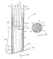
光フアイバープローブ160のもう1つの好ましい実施例が図9A−9Cに図解されている。この実施例では、配送156と収集162のフアイバーは柔軟なチューブ164内に収容され該チューブは遠位の環状ハウジング166に取付られる。ハウジング166はフアイバーリテーナー106と、カルサイト(calcite)、水晶又はサフアイヤの様な複屈折結晶とすることが出来る偏光子168とを含んでいる。配送フアイバー156は光源42からの光を偏光子168に配送するが、該偏光子は普通の光線170をアパーチャー175と窓178を通して配送する。アパーチャー175を通して戻る光は普通の成分170と特別の成分172を有する。直角な成分はフアイバー162により収集され、平行な成分はフアイバー161により収集される。該配送フアイバー156は該結晶168の光軸176に沿って位置付けられている。フアイバー161と156は吸収プレート174のアパーチャー175に沿うよう整合されている。
【0060】
本発明はその好ましい実施例を参照して特に示され説明されたが、付属する請求項により規定される本発明の精神と範囲から離れることなく形式と詳細で種々の変更がその中でなされるかも知れないことは当業者により理解されるところである。
【図面の簡単な説明】
【図1】 偏光ベースの光散乱分光システムの好ましい実施例を図解している。
【図2A及び2B】 それぞれ平行及び直角偏光に対する2層組織仮想体(two-layered tissue phantum)(血液及びBaSO4を含むゲルの頂部上のポリスチレンビーヅ)の反射スペクトルである{特性ヘモグロビンデイップ(dips)に注意}。
【図3A−D】 (A)水(比屈折率n=1.19)中の4.56μmビーヅ、(B)水(n=1.19)中の9.5μmビーヅ、(C)グリコール(n=1.09)中の5.7μmビーヅ、(D)グリコール(n=1.07)中の8.9μmビーヅ、に対する2つの偏光の差を図解しており、ここで信号(破線)はミー(Mie)計算(実線)と良く一致しており、ホモグロビンの吸収の特徴は完全に除去されている。
【図4】 後方散乱光の偏光(残留)成分のスペクトルである:T84癌性結腸細胞(cancerous colonic cells)の偏光後方散乱のミー計算の対実験データ適合度であり、ここで最も良い適合は次のセットのパラメーターを提供する:平均寸法10.2μm、標準偏差1.5μm、比屈折率1.045、そして該寸法と標準偏差は光顕微鏡検査法を使用して測定されたものと一致する。
【図5】 後方散乱光の偏光(残留)成分のスペクトルである:正常な腸内細胞(normal intestinal cells)の偏光後方散乱のミー計算の対実験データ適合度であり、ここで最も良い適合は次のセットのパラメーターを提供する:平均寸法5.0μm、標準偏差0.5μm、比屈折率1.035、そして該寸法と標準偏差は光顕微鏡検査法を使用して測定されたものと一致する。
【図6】 正常な腸内細胞とT84癌性結腸細胞の核寸法分布を示すが、ここで各場合、実線は該データから抽出された分布であり、破線は光顕微鏡検査法を使用して測定された分布である。
【図7】 本発明に従って組織の生体内光学的測定を行うための光フアイバープローブシステムを略図的に図解する。
【図8A及び8B】 本発明の好ましい実施例のプローブの遠位の端部を示す。
【図9A−9C】 本発明の光フアイバープローブのもう1つの好ましい実施例を図解する。[0001]
[Related Applications]
This application claims priority from US application Ser. No. 09 / 237,153, filed Jan. 25, 1999, the entire contents of which are incorporated herein by reference.
[0002]
[Government support]
This invention was supported in whole or in part by the National Institute for Health grant number P41RR02954. The US government has certain rights in the invention.
[0003]
BACKGROUND OF THE INVENTION
More than 90% of cancer lesions are related to the epithelium of the organ. Some of the most common forms of epithelial cancers such as colorectal, esophageal, bladder, cervical and laryngeal cancer are called dysplasia, well Has a defined, detectable precancerous stage. Dysplasia is characterized by the sequential accumulation of mutations in defined oncogenes and tumor suppressor genes. If detected, the absolute majority of the dysplastic lesions are cured. Clinical efforts to detect and treat this precancerous stage of epithelial cancer have been shown to reduce mortality.
[0004]
Diagnosis of epithelial dysplasia is difficult because it typically does not form a macroscopic structure like a polyp and is usually visible only after the cancer has developed. Standard methods for detecting epithelial malformations are based on random biopsies and pathological examination of the colored biopsy material. However, a random biopsy has a high sampling error. In many cases, less than 1% of the epithelial surface is examined at risk for dysplasia.
[0005]
All types of epithelial dysplasia have some common characteristics: increase in nuclei to cytoplasm ratio, nuclear hyperpigmentation, epithelial cell nuclei expansion and epithelial cell stratification with increased numbers. Despite these well-characterized epithelial changes, classification is a difficult process, even among experienced pathologists, as shown by high observer disagreement.
[0006]
SUMMARY OF THE INVENTION
Non-invasive, in vivo methods for detecting epithelial dysplasia provide epithelial surface monitoring and pathological diagnosis of human precancerous conditions.
[0007]
Optical techniques are well adapted to replace random biopsies because they are non-invasive, do not require tissue removal, and can be performed in vivo. Furthermore, they are fast (applicable in real time), relatively inexpensive, can operate on a microscopic scale, and thus find very small malformed sites. The latter is very easy to miss in a random biopsy.
[0008]
The present invention relates to light scattering spectroscopy of polarized light to provide information about scatterers in the surface layer of turbid media such as tissue. This process does not need to make use of fluorescence or absorption spectral features, but rather uses the scattering properties of surface tissues such as epithelial layers. It can characterize the large scatterers (cell nuclei) of the human epithelium, provide time-dependent information on human tissues, and diagnose human organ dysplasia in vivo in real time.
[0009]
The idea of non-polarized light scattering spectroscopy for determining the characteristics of epithelial tissue is described in US application Ser. No. 08/948, filed Oct. 10, 1997, the entire contents of these applications are incorporated herein by reference. 734 and International Application No. PCT / US98 / 21450, filed Oct. 9, 1998, and assigned to the United States. The main centers of light scattering in the epithelium are organelles like mitochondria and nuclei that have a higher refractive index than that of the surrounding cytoplasm. Backscattered light from the surface epithelial cell nucleus has an oscillatory wavelength dependent component. The periodicity of this component increases with the size of the nucleus and its amplitude is related to the density of the nucleus. Thus, by analyzing the amplitude and frequency of the oscillatory component, the density and size distribution of the epithelial nucleus can be determined. Normal nuclei have a characteristic diameter l = 4-7 μm. In contrast, dysplastic nuclei can be as large as 20 μm. Nuclear size and density are important indicators of neoplastic precancerous changes in biological tissues. The ability to measure nuclear size distribution in vivo in real time has valuable applications in clinical medicine. This allows non-invasive and real-time diagnosis of precancerous changes in various human organs such as the esophagus, colon, bladder, oral cavity, cervix, and others.
[0010]
The epithelium covers the surface of human organs. Epithelial thickness ranges from 20 μm (single cell layer) to 200-300 μm (multiple cell layers). Below the epithelium is a relatively acellular connective, muscular tissue layer. Since dysplasia is limited to the epithelium, it is important to distinguish between signals associated with the epithelium and the underlying tissue. A backscattered component responsible for information about the surface epithelial nucleus is present in the light reflected from the mucosal tissue. However, it is usually very small in amplitude and easily masked by background signals formed by diffuse scattering from the underlying tissue. In order to analyze the component, the background signal must be removed. The diffuse background can be removed by modeling the general spectral features of the background. However, in order to make the strategy more useful in actual medicine and to be able to diagnose dysplasia in vivo, in real time, and in various organs, the diffusive component of the scattered light is removed significantly. It is necessary to develop a more robust method of removal.
[0011]
The present invention provides a method for measuring the scattering characteristics of epithelial cells by using polarized light spectroscopy. The first polarized light loses its polarization while passing through a turbid medium (tissue is an example of a turbid medium). On the other hand, the backscattered light retains its polarization after one scattering. Thus, the light scattered by the epithelial cells can be distinguished by removing the non-polarized component of the scattered light. The residual spectrum can be further analyzed so that the size distribution of the nuclei and their density can be determined.
[0012]
The preferred embodiment of the present invention includes an optical fiber light delivery and collection system for tissue diagnosis. The fiber optic system can be received at the proximal and distal ends of the probe housing, where the distal ends are the tissueIn vivoIt can be inserted into various lumens of the human body for measurement. A polarizer is used on the distal end of both the delivery and collection fibers. With an optical fiber that preserves the polarization of the light, the polarizer is positioned at the proximal end of the probe. In a three fiber system, the probe can use a central delivery fiber and two off-center collection fibers that collect two different polarization components of light returning from the tissue. The polarizer can be a birefringent crystal material such as quartz, sapphire or calcite. The calcite must be sealed from the operating environment.
[0013]
[Detailed Description of the Invention]
The foregoing and other objects, features and advantages of the invention will become apparent from the following more particular description of a preferred embodiment of the invention, illustrated in the accompanying drawings, in which the same reference is made throughout the various figures. Refer to parts with the same letter. The drawings are not necessarily to scale, emphasis is placed on illustrating the principles of the invention.
[0014]
In order to determine the properties of epithelial cells, the measured spectrum of backscattered light can be correlated with a model or representative. Using Mie theory, which provides a precise solution to the problem of light scattering by a spherical object of arbitrary size, the size and relative refractive indexes of the scatterer can be determined.
[0015]
For polarized incident light, the light scattered by a spherical particle having a diameter d is
[0016]
[Outside 1]
It has components that are polarized in rows (p) and perpendicularly (s). Intensities of these components IPAnd ISIs the incident light intensity I asP (0)And IS (0)Related to the
[0018]
[Expression 1]
Where k is the wavenumber of the incident light and S1And S2Can be numerically calculated using Mie theory, scattering amplitudes, and s1And s2Is incident and diffuse
[0020]
[Outside 2]
[Expression 2]
[Outside 3]
[Equation 3]
It is.
[0025]
Consider two layers of scattering media, such as epithelial tissue, where a thin layer of large scattering (d >> λ) covers a very turbid layer of underlying tissue. Each of these layers causes a different type of scattering. This two-layer system represents the optical properties of many human tissues, with the first layer correlated with the epithelium and the second layer correlated with other tissue layers below the epithelium. Since the top layer is optically thin, it does not allow multiple scattering. A small portion of incident linearly polarized light is backscattered by particles in the upper layer. The remaining signal penetrates into the optically thick second layer. Light propagation through the second layer is randomized by multiple scattering. This diffusive light returns to the surface if it is not absorbed in the second layer. Thus, emerging light has two contributions, one from the light backscattered by the particles of the first layer, IbAnd the other side diffusely reflected from the second layer, IdIt is. IbIs flat to the polarization of the incident light.
[0026]
[Outside 4]
Depending on the wavelength λ = π / k of the scattered light, the scattering dimension d and the ratio of its refractive index to the refractive index of the surrounding medium, the relative refractive index n. Therefore, the residual luminance spectrum varies with the size of the scatterer (scatterer's size) and relative refractive index. Thus, the size and refractive index of the scatterer can be found by applying the Mie theory expression using equations (3)-(5) to the residual luminance spectrum.
[0028]
A
[0029]
[Outside 5]
![]()
d polarization beam splitter cube) 28, which acts as our analyzer {Melles Griot, Inc.}. The output from this analyzer is a multi-channel spectrometer {Florida, Dunedin City, Ocean Optics, Quadruple Spectrometer, Model through a
[0031]
The beams are not perfectly collinear, which causes a small amount of distortion as they pass through the polarizer and analyzer cube. Furthermore, the beam splitter has different reflectivities for s and p polarizations. Diffuse reflective white surface as a standard for correcting wavelength inhomogeneities and for calibrating signals in the two channels
[0032]
[Outside 6]
Toll non-uniformity is eliminated. Thus, the experiment actually measured the normalized residual luminance, ΔI,
[0034]
[Expression 4]
Measurements were made on a simple 1 and 2 layer system to determine the operating parameters. The single layer system included polystyrene beads {Polyscience, Inc.} of various sizes ranging from 0.5 μm to 1.0 μm embedded in deionized water, glycol, or glycerol. The thickness of these layers was varied so that the optical thickness τ ranged from 0.1 to 5 (photons propagating through a medium with τ = 1 on average undergo one scattering event). A large 4-10 μm beet bowl was used to represent the cell nucleus. The relative refractive index of polystyrene beads in water is about 1.2 (absolute refractive index is about n = 1.59), which is substantially higher than that of the cell nucleus against the cytoplasm in the range of 1.03 to 1.1. In order to reduce the relative refractive index of the rice cake and thus better approximate biological conditionsa= 1.45) and glycerol (na= 1.48) was used instead of water.
[0036]
In the measurement of the one layer, the component of backscattered light having the same polarization state as the incoming light
[0037]
[Outside 7]
![]()
About 100 times larger. This establishes that a single scattering from a large spherical particle preserves the polarization.
[0039]
In measurements using the two-layer model, the first layer consisted of polystyrene beads embedded in water, glycol or glycerol and was prepared as in the one-layer measurement. The second layer comprised a gel with a solution of barium sulfate powder that provided the scattering properties of the second layer and human blood. The hemoglobin content of the blood provided the absorption characteristics of the model. This physical model simulated the epithelium and the underlying tissue. The regulation of barium sulfate powder and blood concentration, scattering and absorption was done in the same way as those of biological tissues, because hemoglobin is known to be the main absorber in the optical spectral region.
[0040]
[Outside 8]
The minute spectrum is shown. In this measurement, the first layer contains bees embedded in glycol. The beak has an average diameter of 4.56 μm. The standard deviation of their dimensions was 0.03 μm. The optical thickness of the first layer was τ−0.8. The second layer is optically thick and its scattering and absorption properties are comparable to those of biological tissue.
[0042]
[Outside 9]
Dominated by oglobin absorption). At the same time, the characteristic spectrum characteristics of the light scattered by the 4.56 μm bead in the first layer, that is, the appellant ripple structure
[0044]
[Outside 10]
Seen in the spectrum.
[0046]
The residual spectrum ΔI is shown in FIG. 3A. No characteristic of hemoglobin absorption was seen and the diffusive background coming from the second layer was completely removed. The ripple structural characteristics of scattering from the sphere are obvious. A comparison with the Mie theory representation for a scatterer with d = 4.56 μm, Δd = 0.03 μm and n = 1.035 corresponding to μm shown in FIG. Residual spectra obtained from measurements at other bead dimensions embedded in any of the media used do not have measurable diffusive background components and are consistent with Mie theory. FIG. 3B shows the agreement between the theory and the measurement at the 9.5 μm beak.
[0047]
Similarly, the measurement results for 5.7 μm and 8.9 μm in glycerol and glycol are shown in FIGS. 3 (C) and 3 (D), respectively. Mie theory corresponds to the measured value in this case as well. As the relative refractive index becomes smaller, the high-frequency ripple structure decreases. Low frequency vibrations clearly remain. Measurements have shown that the instrument can detect signals even from bean solution with a low optical thickness such as 0.05. The small discrepancy seen in the spectrum comes from incomplete instrument calibration for the wavelength dependence of the optical elements used. The beam is not perfectly collinear, so some imperfection occurs in the polarization signals from the two channels when the beam passes through the polarizer and the analyzer element. Furthermore, the used beam splitter has different reflectivities for s and p polarized beams. However, using the only white standard, the two channel signals were corrected for any wavelength inhomogeneities and used for signal calibration.
[0048]
Measurements using cell monolayers are performed and the results are described in conjunction with FIGS. 4-6. A barium sulfate powder solution below the molecular membrane and a gel layer containing human blood are used to represent the underlying tissue. Barium sulfate and blood concentrations were adjusted to match the optical properties of biological tissues. Three types of cells were measured: normal intestinal cells, T84 cancerous colon cells, and fibrocytes. The measurement was the same as the measurement using the bean paste. However, the cell nuclei had a relative index of refraction that was smaller than that of bean straw as well as a larger size distribution that substantially excluded the ripple structure. An adaptation of the observed residual spectrum to the Mie theory was made. The three parameters in the fitting process are the average size of the nucleus, the standard deviation of the size (assuming a Gaussian size distribution), and the relative refractive index.
[0049]
For normal intestinal cells, the best fit was obtained using d = 5.0 μm, Δd = 0.5 μm, and n = 1.045 (FIG. 4). In fibrocytes, d = 7.0 μm, Δd = 1.0 μm and n = 1.51 were obtained. For T84 colon cancer cells, the corresponding values are d = 9.8 μm, Δd = 1.5 μm, and n = 1.04 (FIG. 5).
[0050]
To check these results, the average size distribution of the cell nuclei was measured using light microscopy. The dimensions and their standard deviation are consistent with the parameters of Mie theory. A histogram showing the size distribution obtained with normal T84 cells is shown in FIG. The accuracy of the average dimension was estimated to be 0.1 μm and the accuracy of n was estimated to be 0.001. The larger value of n obtained with cancerous cells is noteworthy, which is consistent with the hyperchromaticity of cancer cell nuclei observed in conventional histopathology of colored tissue parts.
[0051]
If the average dimension d of the nucleus, the standard deviation Δd of the dimension, and the relative refractive index n change, the backscatter signal can be explained by Mie theory. It should be noted that in Mie theory, the dependence on d and n does not necessarily come as a (n−1) d product. Thus, the residual spectrum has enough information to extract d and n simultaneously.
[0052]
The size distribution in the molecular film was compared with light microscopy and was in good agreement with all three lines of cells. The dimensional accuracy and standard deviation extraction is about 0.1 μm, which is the aspect that distinguishes the nucleus of various cell types, including cancerous and non-cancerous cells of the same organ. Make it useful.
[0053]
The ability to detect cell nuclei expansion and changes in the refractive index of the nuclei (which may be related to the amount of DNA and protein in the nuclei) has valuable applications in clinical medicine.
[0054]
The method of tissue diagnosis can also be performed with a diagnostic device in which light is delivered to points on the tissue surface and collected and analyzed at each of those points on the tissue surface. In in vivo systems, optical fibers are used to distribute and collect light. A fiber optic probe can be inserted in an endoscopic biopsy channel or any similar device (depending on the process being studied and the type of organ). A polarizer and analyzer are placed at the tip of the probe in the front of the delivery and collection fiber. Such instruments can be used during routine endoscopic procedures to detect precancerous changes in vivo in real time.
[0055]
Such a
[0056]
The probe system can comprise an optical fiber probe having a distal end that incorporates a polarizer as seen in FIGS. 8A and 8B.
[0057]
8A and 8B show the distal end of the
[0058]
The back-scattered light has two polarization components corresponding to components parallel and perpendicular to the incident light. The two are distinguished by two different birefringence analyzers represented by two cross-sectional ring elements 122,126. The
[0059]
Another preferred embodiment of the
[0060]
Although the invention has been particularly shown and described with reference to preferred embodiments thereof, various changes can be made therein in form and detail without departing from the spirit and scope of the invention as defined by the appended claims. It will be appreciated by those skilled in the art that this may be the case.
[Brief description of the drawings]
FIG. 1 illustrates a preferred embodiment of a polarization-based light scattering spectroscopy system.
2A and 2B two-layered tissue phantum (blood and BaSO for parallel and right-polarized light, respectively)FourIs a reflection spectrum of polystyrene beads on the top of the gel containing {note the characteristic hemoglobin dips}.
FIGS. 3A-D (A) 4.56 μm beetle in water (relative index n = 1.19), (B) 9.5 μm beetle in water (n = 1.19), (C) glycol ( illustrates the difference between the two polarizations for a 5.7 μm bean meal in (n = 1.09) and an 8.9 μm bean meal in (D) glycol (n = 1.07), where the signal (dashed line) is It is in good agreement with the Mie calculation (solid line) and the homoglobin absorption feature is completely eliminated.
FIG. 4 is the spectrum of the polarized (residual) component of backscattered light: T84's M-calculation of polarized backscatter of cancerous colonic cells, where the best fit is Provide the following set of parameters: average size 10.2 μm, standard deviation 1.5 μm, relative refractive index 1.045, and the size and standard deviation are consistent with those measured using light microscopy .
FIG. 5 is the spectrum of the polarized (residual) component of the backscattered light: the Mie calculation of the polarized backscatter of normal intestinal cells versus the experimental data fit, where the best fit is Provide the following set of parameters: mean dimension 5.0 μm, standard deviation 0.5 μm, relative refractive index 1.035, and the dimensions and standard deviation are consistent with those measured using light microscopy. .
FIG. 6 shows the nuclear size distribution of normal intestinal cells and T84 cancerous colon cells, where in each case the solid line is the distribution extracted from the data and the dashed line is using light microscopy The measured distribution.
FIG. 7 schematically illustrates an optical fiber probe system for performing in vivo optical measurements of tissue in accordance with the present invention.
8A and 8B show the distal end of the probe of the preferred embodiment of the present invention.
FIGS. 9A-9C illustrate another preferred embodiment of the optical fiber probe of the present invention. FIGS.
Claims (14)
光源に光学的に結合された光フアイバーケーブルであって、光源から患者の組織に複数の波長を有する光を送る光フアイバーケーブルと、
該光フアイバーケーブルに光学的に接続され、該ケーブルを介して組織に向けられる入射光を偏光する偏光子と、
該光フアイバーケーブルを介して組織から戻って来た、波長の関数として周期性である成分を有する光の偏光成分を分離するアナライザーと、
該アナライザーに光学的に連結され、周期性である成分を有する光の分離された偏光成分を検出し、組織中の構造の寸法を決定するためのスペクトルデータを生成する検出器システムと
を具備していることを特徴とする光フアイバープローブ。In an optical fiber probe that measures the surface layer of tissue,
An optical fiber cable optically coupled to a light source, wherein the optical fiber cable transmits light having a plurality of wavelengths from the light source to a patient's tissue;
A polarizer optically connected to the optical fiber cable and polarizing incident light directed to tissue through the cable;
An analyzer that separates the polarization component of the light having a component that is periodic as a function of wavelength, returning from the tissue via the optical fiber cable;
A detector system optically coupled to the analyzer for detecting a separated polarization component of light having a component that is periodic and generating spectral data for determining the size of the structure in the tissue. An optical fiber probe characterized by
該ハウジング内に配置され、光フアイバーを介して該光源に結合された少なくとも1つの中央供給フアイバーであって、該偏光子が該中央供給フアイバーに連結され、該光フアイバーケーブルを介して組織に向けられる入射光を偏光する中央供給フアイバーと、
該ハウジング内に配置され、少なくとも2つの異なった偏光成分を有し、その1つの成分が、波長の関数として周期を有する組織からもとった光を収集する少なくとも1つのオフセンター収集フアイバーとを具備し、
該偏光子が、該少なくとも1つのオフセンター収集フアイバに接続されており、組織から戻った光の偏光成分を分離する請求項1に記載のプローブ。A housing having a proximal end and a distal end;
At least one central supply fiber disposed within the housing and coupled to the light source via an optical fiber, wherein the polarizer is coupled to the central supply fiber and is directed to tissue via the optical fiber cable. A central supply fiber that polarizes the incident light produced;
At least one off-center collection fiber disposed within the housing and having at least two different polarization components, one component collecting light originating from tissue having a period as a function of wavelength; And
The probe according to claim 1, wherein the polarizer is connected to the at least one off-center collection fiber and separates a polarization component of light returning from the tissue.
Applications Claiming Priority (3)
| Application Number | Priority Date | Filing Date | Title |
|---|---|---|---|
| US09/237,153 US6404497B1 (en) | 1999-01-25 | 1999-01-25 | Polarized light scattering spectroscopy of tissue |
| US09/237,153 | 1999-01-25 | ||
| PCT/US2000/001967 WO2000042912A1 (en) | 1999-01-25 | 2000-01-25 | Polarized light scattering spectroscopy of tissue |
Publications (3)
| Publication Number | Publication Date |
|---|---|
| JP2002535027A JP2002535027A (en) | 2002-10-22 |
| JP2002535027A5 JP2002535027A5 (en) | 2007-03-15 |
| JP4516217B2 true JP4516217B2 (en) | 2010-08-04 |
Family
ID=22892544
Family Applications (1)
| Application Number | Title | Priority Date | Filing Date |
|---|---|---|---|
| JP2000594380A Expired - Fee Related JP4516217B2 (en) | 1999-01-25 | 2000-01-25 | Polarization scattering spectroscopy of tissue |
Country Status (10)
| Country | Link |
|---|---|
| US (2) | US6404497B1 (en) |
| EP (1) | EP1148811A1 (en) |
| JP (1) | JP4516217B2 (en) |
| KR (1) | KR20010101687A (en) |
| CN (1) | CN1211046C (en) |
| AU (1) | AU3351000A (en) |
| CA (1) | CA2359643A1 (en) |
| HK (1) | HK1041593A1 (en) |
| NZ (1) | NZ513116A (en) |
| WO (1) | WO2000042912A1 (en) |
Families Citing this family (110)
| Publication number | Priority date | Publication date | Assignee | Title |
|---|---|---|---|---|
| US7616319B1 (en) | 1995-09-20 | 2009-11-10 | James D. Welch | Spectroscopic ellipsometer and polarimeter systems |
| US7158231B1 (en) * | 1995-09-20 | 2007-01-02 | J.A. Woollam Co., Inc. | Spectroscopic ellipsometer and polarimeter systems |
| US7633625B1 (en) | 1995-09-20 | 2009-12-15 | J.A. Woollam Co., Inc. | Spectroscopic ellipsometer and polarimeter systems |
| US6404497B1 (en) | 1999-01-25 | 2002-06-11 | Massachusetts Institute Of Technology | Polarized light scattering spectroscopy of tissue |
| US6717668B2 (en) * | 2000-03-07 | 2004-04-06 | Chemimage Corporation | Simultaneous imaging and spectroscopy apparatus |
| US6734962B2 (en) | 2000-10-13 | 2004-05-11 | Chemimage Corporation | Near infrared chemical imaging microscope |
| AU2001251164B2 (en) | 2000-03-28 | 2006-11-02 | Board Of Regents, The University Of Texas System | Methods and apparatus for diagnostic multispectral digital imaging |
| US6697652B2 (en) * | 2001-01-19 | 2004-02-24 | Massachusetts Institute Of Technology | Fluorescence, reflectance and light scattering spectroscopy for measuring tissue |
| US7202091B2 (en) * | 2001-04-11 | 2007-04-10 | Inlight Solutions, Inc. | Optically similar reference samples |
| JP5259033B2 (en) * | 2001-08-03 | 2013-08-07 | オリンパス株式会社 | Endoscope system |
| US8308797B2 (en) | 2002-01-04 | 2012-11-13 | Colibri Heart Valve, LLC | Percutaneously implantable replacement heart valve device and method of making same |
| WO2003062798A1 (en) * | 2002-01-18 | 2003-07-31 | Newton Laboratories, Inc. | Spectroscopic diagnostic methods and system |
| GB0202654D0 (en) * | 2002-02-06 | 2002-03-20 | Univ Nottingham | Examination of superficial regions of a body |
| US20040010204A1 (en) * | 2002-03-28 | 2004-01-15 | Pearl Technology Holdings, Llc | Electronic/fiberoptic tissue differentiation instrumentation |
| US8131332B2 (en) * | 2002-04-04 | 2012-03-06 | Veralight, Inc. | Determination of a measure of a glycation end-product or disease state using tissue fluorescence of various sites |
| AU2003234315A1 (en) * | 2002-04-30 | 2003-11-17 | William R. Moyle | Sensors for biomolecular detection and cell classification |
| WO2004016155A2 (en) * | 2002-08-16 | 2004-02-26 | The Government Of United States Of America As Represented By The Secretary Of The Department Of Health And Human Services | Apparatus for multifocal deposition and analysis and methods for its use |
| US7053783B2 (en) | 2002-12-18 | 2006-05-30 | Biovigilant Systems, Inc. | Pathogen detector system and method |
| US9173562B2 (en) * | 2003-01-23 | 2015-11-03 | The Board Of Regents Of The University Of Texas System | Method and apparatus for diagnosing neovascularized tissues |
| US7623908B2 (en) | 2003-01-24 | 2009-11-24 | The Board Of Trustees Of The University Of Illinois | Nonlinear interferometric vibrational imaging |
| US7102758B2 (en) | 2003-05-06 | 2006-09-05 | Duke University | Fourier domain low-coherence interferometry for light scattering spectroscopy apparatus and method |
| AU2003289004A1 (en) * | 2003-06-11 | 2005-01-04 | Kose Corporation | Skin evaluation method and image simulation method |
| PL2308961T3 (en) * | 2003-08-25 | 2017-08-31 | Monsanto Technology Llc | Tubulin regulatory elements for use in plants |
| EP1670347A4 (en) * | 2003-09-19 | 2011-05-18 | Gen Hospital Corp | Fluorescence polarization imaging devices and methods |
| WO2005028062A2 (en) * | 2003-09-23 | 2005-03-31 | Research Foundation Of The City University Of New York | Method and apparatus for the separation of fluorescence and elastic scattering produced by broadband illumination using polarization discrimination techniques |
| CA2540110A1 (en) * | 2003-09-23 | 2005-03-31 | Stichting Voor De Technische Wetenschappen | Method and apparatus for backscatter spectroscopy |
| JP2007516009A (en) | 2003-10-03 | 2007-06-21 | アカデミッシュ メディシュ セントラム | Systems and methods for image processing of substrate reflections. |
| SE0400145D0 (en) * | 2004-01-27 | 2004-01-27 | Anders Johansson | An arrangement and method for assessing joints |
| US20060155178A1 (en) * | 2004-03-26 | 2006-07-13 | Vadim Backman | Multi-dimensional elastic light scattering |
| US8060172B2 (en) * | 2004-03-29 | 2011-11-15 | Olympus Corporation | In-vivo information measurement apparatus |
| EP1759184B1 (en) * | 2004-06-17 | 2011-05-18 | Bayer HealthCare, LLC | Coaxial read head for diffuse reflectance measurement |
| KR101170859B1 (en) | 2004-07-30 | 2012-08-02 | 바이오비질런트 시스템즈 인코포레이티드 | Pathogen and particle detector system and method |
| US7417740B2 (en) * | 2004-11-12 | 2008-08-26 | Medeikon Corporation | Single trace multi-channel low coherence interferometric sensor |
| US9131861B2 (en) | 2004-11-30 | 2015-09-15 | Academisch Medisch Centrum | Pulsed lighting imaging systems and methods |
| US7428048B1 (en) * | 2004-12-30 | 2008-09-23 | Spectral Molecular Imaging Inc. | Imaging elastic scattering spectroscopy |
| JP2006208681A (en) * | 2005-01-27 | 2006-08-10 | Olympus Corp | Connection unit and optical scanning type fluorescent observation device |
| US9597024B2 (en) * | 2005-02-09 | 2017-03-21 | Medici Instruments Llc | Methods and apparatuses for noninvasive determinations of analytes |
| WO2006086579A2 (en) * | 2005-02-09 | 2006-08-17 | Inlight Solutions, Inc. | Methods and apparatus for noninvasive determinations of analytes |
| US7586618B2 (en) | 2005-02-28 | 2009-09-08 | The Board Of Trustees Of The University Of Illinois | Distinguishing non-resonant four-wave-mixing noise in coherent stokes and anti-stokes Raman scattering |
| US7515265B2 (en) * | 2005-04-28 | 2009-04-07 | Research Foundation Of The City University Of New York | Imaging systems and methods to improve backscattering imaging using circular polarization memory |
| JP5112312B2 (en) | 2005-07-15 | 2013-01-09 | バイオヴィジラント システムズ インコーポレイテッド | Pathogen and particulate detection system and detection method |
| US20120302892A1 (en) * | 2005-07-25 | 2012-11-29 | Niyom Lue | Portable optical fiber probe-based spectroscopic scanner for rapid cancer diagnosis |
| US20070173736A1 (en) * | 2005-10-07 | 2007-07-26 | Femspec Llc | Apparatus and methods for endometrial biopsies |
| EP2950065A1 (en) | 2005-10-11 | 2015-12-02 | Duke University | Method for fiber-based endoscopic angle-resolved low coherence interferometry |
| US8537366B2 (en) | 2005-10-11 | 2013-09-17 | Duke University | Systems and methods for endoscopic angle-resolved low coherence interferometry |
| US9314164B2 (en) | 2005-10-27 | 2016-04-19 | Northwestern University | Method of using the detection of early increase in microvascular blood content to distinguish between adenomatous and hyperplastic polyps |
| US20070179368A1 (en) * | 2005-10-27 | 2007-08-02 | Northwestern University | Method of recognizing abnormal tissue using the detection of early increase in microvascular blood content |
| US20070129615A1 (en) * | 2005-10-27 | 2007-06-07 | Northwestern University | Apparatus for recognizing abnormal tissue using the detection of early increase in microvascular blood content |
| US20090203977A1 (en) * | 2005-10-27 | 2009-08-13 | Vadim Backman | Method of screening for cancer using parameters obtained by the detection of early increase in microvascular blood content |
| US8131112B1 (en) | 2006-01-23 | 2012-03-06 | Sandia Corporation | Method for detecting cancer in a single cell using mitochondrial correlation microscopy |
| AU2007211061B2 (en) * | 2006-01-31 | 2013-04-18 | The Board Of Trustees Of The University Of Illinois | Method and apparatus for measurement of optical properties in tissue |
| WO2007136880A2 (en) * | 2006-05-19 | 2007-11-29 | Northshore University Health System | Method & apparatus for recognizing abnormal tissue using the detection of early increase in microvascular blood content |
| EP2028996A2 (en) * | 2006-05-30 | 2009-03-04 | Koninklijke Philips Electronics N.V. | Apparatus for depth-resolved measurements of properties of tissue |
| CA2658481A1 (en) * | 2006-07-21 | 2008-01-24 | Oncoscope, Inc. | Protective probe tip, particularly for use on a fiber-optic probe used in an endoscopic application |
| WO2008066911A2 (en) * | 2006-11-30 | 2008-06-05 | Newton Laboratories, Inc. | Spectroscopically enhanced imaging |
| RU2469639C2 (en) * | 2007-02-20 | 2012-12-20 | Конинклейке Филипс Электроникс Н.В. | Optical device for estimating optical depth in sample |
| EP2134240A1 (en) * | 2007-03-12 | 2009-12-23 | Koninklijke Philips Electronics N.V. | A system, computer-readable medium, method, and use for combined epithelial early cancer diagnosis and staging |
| US20090062662A1 (en) * | 2007-08-27 | 2009-03-05 | Remicalm, Llc | Optical spectroscopic device for the identification of cervical cancer |
| EP2188587A4 (en) * | 2007-09-13 | 2017-01-18 | Duke University | Apparatuses, systems, and methods for low-coherence interferometry (lci) |
| US20090099460A1 (en) | 2007-10-16 | 2009-04-16 | Remicalm Llc | Method and device for the optical spectroscopic identification of cervical cancer |
| US8628976B2 (en) | 2007-12-03 | 2014-01-14 | Azbil BioVigilant, Inc. | Method for the detection of biologic particle contamination |
| AU2009204187B2 (en) * | 2008-01-08 | 2015-02-05 | Oncoscope, Inc. | Systems and methods for tissue examination, diagnostic, treatment, and/or monitoring |
| US8983580B2 (en) | 2008-01-18 | 2015-03-17 | The Board Of Trustees Of The University Of Illinois | Low-coherence interferometry and optical coherence tomography for image-guided surgical treatment of solid tumors |
| WO2009105537A2 (en) * | 2008-02-19 | 2009-08-27 | Trustees Of Tufts College | Non-invasive optical characterization of biomaterial mineralization |
| JP5100457B2 (en) * | 2008-03-10 | 2012-12-19 | オリンパスメディカルシステムズ株式会社 | Endoscope observation system |
| JP5380725B2 (en) * | 2008-03-31 | 2014-01-08 | 富士フイルム株式会社 | Optical system, method, and program |
| JP2009283871A (en) * | 2008-05-26 | 2009-12-03 | Fujitsu Ltd | Rework soldering method and its apparatus |
| US20100249607A1 (en) * | 2008-09-26 | 2010-09-30 | Massachusetts Institute Of Technology | Quantitative spectroscopic imaging |
| US9885834B2 (en) | 2009-01-08 | 2018-02-06 | Northwestern University | Probe apparatus for measuring depth-limited properties with low-coherence enhanced backscattering |
| CN102368947A (en) * | 2009-01-08 | 2012-03-07 | 美国生物光学公司 | Probe apparatus for recognizing abnormal tissue |
| EP2389099A1 (en) * | 2009-01-23 | 2011-11-30 | Lev T. Perelman | Endoscopic polarized multispectral light scattering scanning method |
| US9254123B2 (en) | 2009-04-29 | 2016-02-09 | Hansen Medical, Inc. | Flexible and steerable elongate instruments with shape control and support elements |
| JP4805424B2 (en) | 2009-08-20 | 2011-11-02 | オリンパスメディカルシステムズ株式会社 | Biometric apparatus and biometric method |
| JPWO2011043077A1 (en) * | 2009-10-09 | 2013-03-04 | 川崎重工業株式会社 | Identification method and apparatus for undifferentiated pluripotent stem cells and automatic culture method and apparatus |
| CN102883658B (en) * | 2009-11-19 | 2016-06-22 | 调节成像公司 | The method and apparatus analyzing turbid media for using structured lighting to detect via unit piece |
| US9823127B2 (en) | 2010-01-22 | 2017-11-21 | Duke University | Systems and methods for deep spectroscopic imaging of biological samples with use of an interferometer and spectrometer |
| CA2787696A1 (en) | 2010-01-22 | 2011-07-28 | Adam Wax | Multiple window processing schemes for spectroscopic optical coherence tomography (oct) and fourier domain low coherence interferometry |
| CA2800232C (en) | 2010-03-01 | 2015-08-11 | Colibri Heart Valve Llc | Percutaneously deliverable heart valve and methods associated therewith |
| US8977031B2 (en) | 2010-06-25 | 2015-03-10 | Kawasaki Jukogyo Kabushiki Kaisha | Method and device for identifying multipotent stem cell colony, and method and device for automatically culturing multipotent stem cells |
| CN103153384B (en) | 2010-06-28 | 2016-03-09 | 科利柏心脏瓣膜有限责任公司 | For the device of device in the delivery of vascular of chamber |
| US8827948B2 (en) | 2010-09-17 | 2014-09-09 | Hansen Medical, Inc. | Steerable catheters |
| US9737400B2 (en) | 2010-12-14 | 2017-08-22 | Colibri Heart Valve Llc | Percutaneously deliverable heart valve including folded membrane cusps with integral leaflets |
| WO2013011778A1 (en) | 2011-07-15 | 2013-01-24 | オリンパスメディカルシステムズ株式会社 | Probe |
| US9138166B2 (en) | 2011-07-29 | 2015-09-22 | Hansen Medical, Inc. | Apparatus and methods for fiber integration and registration |
| JP5623470B2 (en) * | 2012-07-06 | 2014-11-12 | 富士フイルム株式会社 | ENDOSCOPE SYSTEM, ENDOSCOPE SYSTEM PROCESSOR DEVICE, AND ENDOSCOPE CONTROL PROGRAM |
| KR102028199B1 (en) * | 2012-08-28 | 2019-10-04 | 한국전자통신연구원 | Medical diagnosis device and method for controlling the device |
| US8892192B2 (en) | 2012-11-07 | 2014-11-18 | Modulated Imaging, Inc. | Efficient modulated imaging |
| US10149720B2 (en) | 2013-03-08 | 2018-12-11 | Auris Health, Inc. | Method, apparatus, and a system for facilitating bending of an instrument in a surgical or medical robotic environment |
| US10376672B2 (en) | 2013-03-15 | 2019-08-13 | Auris Health, Inc. | Catheter insertion system and method of fabrication |
| US9763741B2 (en) | 2013-10-24 | 2017-09-19 | Auris Surgical Robotics, Inc. | System for robotic-assisted endolumenal surgery and related methods |
| CN103781253B (en) * | 2014-01-23 | 2015-08-26 | 安徽理工大学 | A kind of method and apparatus controlling wideband light source stabilized intensity |
| US10792464B2 (en) | 2014-07-01 | 2020-10-06 | Auris Health, Inc. | Tool and method for using surgical endoscope with spiral lumens |
| US9744335B2 (en) | 2014-07-01 | 2017-08-29 | Auris Surgical Robotics, Inc. | Apparatuses and methods for monitoring tendons of steerable catheters |
| US9561083B2 (en) | 2014-07-01 | 2017-02-07 | Auris Surgical Robotics, Inc. | Articulating flexible endoscopic tool with roll capabilities |
| CN104523241B (en) * | 2015-01-21 | 2016-08-24 | 浙江大学 | The detection device of a kind of biological organism optical characteristic and detection method |
| US11819636B2 (en) | 2015-03-30 | 2023-11-21 | Auris Health, Inc. | Endoscope pull wire electrical circuit |
| CN106092905B (en) * | 2016-06-21 | 2021-06-22 | 北京化工大学 | Polarized infrared spectrometer |
| US10463439B2 (en) | 2016-08-26 | 2019-11-05 | Auris Health, Inc. | Steerable catheter with shaft load distributions |
| CN110769736B (en) | 2017-05-17 | 2023-01-13 | 奥瑞斯健康公司 | Replaceable working channel |
| CN107202773B (en) * | 2017-06-01 | 2019-07-05 | 重庆大学 | A kind of cell cycle scattered light intensity method for establishing model using polystyrene spheres |
| WO2018231724A1 (en) * | 2017-06-12 | 2018-12-20 | Trustees Of Boston University | Systems and methods for oblique laser scanning |
| US11395726B2 (en) | 2017-09-11 | 2022-07-26 | Incubar Llc | Conduit vascular implant sealing device for reducing endoleaks |
| JP7305668B2 (en) | 2018-03-28 | 2023-07-10 | オーリス ヘルス インコーポレイテッド | Medical device with variable bending stiffness profile |
| US10898276B2 (en) | 2018-08-07 | 2021-01-26 | Auris Health, Inc. | Combining strain-based shape sensing with catheter control |
| JP7405080B2 (en) * | 2018-08-13 | 2023-12-26 | ソニーグループ株式会社 | Medical system, medical light source device, and operating method of medical light source device |
| WO2020068853A2 (en) | 2018-09-26 | 2020-04-02 | Auris Health, Inc. | Articulating medical instruments |
| WO2020180755A1 (en) * | 2019-03-01 | 2020-09-10 | Sri International | Apparatuses and methods involving multi-modal imaging of a sample |
| US11617627B2 (en) | 2019-03-29 | 2023-04-04 | Auris Health, Inc. | Systems and methods for optical strain sensing in medical instruments |
| KR20220050151A (en) | 2019-08-15 | 2022-04-22 | 아우리스 헬스, 인코포레이티드 | Medical device having multiple bend sections |
| CN110672527A (en) * | 2019-08-30 | 2020-01-10 | 南京航空航天大学 | Cervical cancer precancerous lesion screening system and screening method thereof |
Family Cites Families (63)
| Publication number | Priority date | Publication date | Assignee | Title |
|---|---|---|---|---|
| US3675768A (en) | 1969-03-17 | 1972-07-11 | Gildardo Legorreta Sanchez | Method and apparatus for classifying and segregating particles with electrical and optical means |
| US4281931A (en) | 1977-12-21 | 1981-08-04 | Machida Endoscope Co., Ltd. | Measuring apparatus comprising light optics utilizing cylindrical focusing glass fiber |
| US4515165A (en) | 1980-02-04 | 1985-05-07 | Energy Conversion Devices, Inc. | Apparatus and method for detecting tumors |
| US4336809A (en) | 1980-03-17 | 1982-06-29 | Burleigh Instruments, Inc. | Human and animal tissue photoradiation system and method |
| US4625167A (en) | 1983-07-05 | 1986-11-25 | Sigma Research, Inc. | Flaw imaging in ferrous and nonferrous materials using magneto-optic visualization |
| US4948974A (en) | 1984-06-25 | 1990-08-14 | Nelson Robert S | High resolution imaging apparatus and method for approximating scattering effects |
| US4829184A (en) | 1984-06-25 | 1989-05-09 | Nelson Robert S | Reflective, transmissive high resolution imaging apparatus |
| JPS6125030A (en) | 1984-07-13 | 1986-02-03 | Hitachi Ltd | Fluorescence-polarization measuring apparatus |
| US4884886A (en) | 1985-02-08 | 1989-12-05 | The United States Of America As Represented By The Department Of Energy | Biological particle identification apparatus |
| US5106387A (en) | 1985-03-22 | 1992-04-21 | Massachusetts Institute Of Technology | Method for spectroscopic diagnosis of tissue |
| US4718417A (en) | 1985-03-22 | 1988-01-12 | Massachusetts Institute Of Technology | Visible fluorescence spectral diagnostic for laser angiosurgery |
| EP0195375B1 (en) | 1985-03-22 | 1994-09-21 | Massachusetts Institute Of Technology | Catheter for laser angiosurgery |
| US4655225A (en) | 1985-04-18 | 1987-04-07 | Kurabo Industries Ltd. | Spectrophotometric method and apparatus for the non-invasive |
| JPS62116263A (en) | 1985-11-15 | 1987-05-27 | Olympus Optical Co Ltd | Method and apparatus for measuring immunoreaction using multiple scattering of linearly polarized light |
| JPS62247232A (en) | 1986-04-21 | 1987-10-28 | Agency Of Ind Science & Technol | Fluorescence measuring apparatus |
| JPH0797081B2 (en) | 1987-03-25 | 1995-10-18 | 日本分光工業株式会社 | Crystal orientation analyzer utilizing polarization characteristics of Raman scattered light |
| DE58903504D1 (en) | 1988-07-19 | 1993-03-25 | Siemens Ag | METHOD FOR MEASURING THE CONCENTRATION OF OPTICALLY ACTIVE SUBSTANCES AND ARRANGEMENT FOR IMPLEMENTING THE METHOD. |
| US5284137A (en) | 1988-07-26 | 1994-02-08 | Manfred Kessler | Process and device for the determination of local dye concentrations and of scattering parameters in animal and human tissues |
| US5402778A (en) | 1993-01-19 | 1995-04-04 | Nim Incorporated | Spectrophotometric examination of tissue of small dimension |
| US5596987A (en) | 1988-11-02 | 1997-01-28 | Noninvasive Technology, Inc. | Optical coupler for in vivo examination of biological tissue |
| SE462408B (en) | 1988-11-10 | 1990-06-18 | Pharmacia Ab | OPTICAL BIOSENSOR SYSTEM USING SURFACE MONITORING RESONSE FOR THE DETECTION OF A SPECIFIC BIOMOLIC CYCLE, TO CALIBRATE THE SENSOR DEVICE AND TO CORRECT FOUND BASELINE OPERATION IN THE SYSTEM |
| US5386827A (en) | 1993-03-30 | 1995-02-07 | Nim Incorporated | Quantitative and qualitative in vivo tissue examination using time resolved spectroscopy |
| US4953978A (en) | 1989-03-03 | 1990-09-04 | Coulter Electronics Of New England, Inc. | Particle size analysis utilizing polarization intensity differential scattering |
| US5014709A (en) | 1989-06-13 | 1991-05-14 | Biologic Systems Corp. | Method and apparatus for high resolution holographic imaging of biological tissue |
| US5061075A (en) | 1989-08-07 | 1991-10-29 | Alfano Robert R | Optical method and apparatus for diagnosing human spermatozoa |
| US5369496A (en) | 1989-11-13 | 1994-11-29 | Research Foundation Of City College Of New York | Noninvasive method and apparatus for characterizing biological materials |
| US5419321A (en) | 1990-05-17 | 1995-05-30 | Johnson & Johnson Professional Products Limited | Non-invasive medical sensor |
| DE69121633T2 (en) | 1990-05-22 | 1997-01-16 | Japan Res Dev Corp | Method and apparatus for measuring spectral absorption in opaque material and method and apparatus for measuring a distribution of microscopic absorption |
| US5434669A (en) * | 1990-10-23 | 1995-07-18 | Olympus Optical Co., Ltd. | Measuring interferometric endoscope having a laser radiation source |
| IL96483A (en) | 1990-11-27 | 1995-07-31 | Orbotech Ltd | Optical inspection method and apparatus |
| US5168162A (en) | 1991-02-04 | 1992-12-01 | Cornell Research Foundation, Inc. | Method of detecting the presence of anomalies in exfoliated cells using infrared spectroscopy |
| US5784162A (en) | 1993-08-18 | 1998-07-21 | Applied Spectral Imaging Ltd. | Spectral bio-imaging methods for biological research, medical diagnostics and therapy |
| US5280788A (en) | 1991-02-26 | 1994-01-25 | Massachusetts Institute Of Technology | Devices and methods for optical diagnosis of tissue |
| US5303026A (en) | 1991-02-26 | 1994-04-12 | The Regents Of The University Of California Los Alamos National Laboratory | Apparatus and method for spectroscopic analysis of scattering media |
| US5203328A (en) | 1991-07-17 | 1993-04-20 | Georgia Tech Research Corporation | Apparatus and methods for quantitatively measuring molecular changes in the ocular lens |
| DE4129438A1 (en) | 1991-09-04 | 1993-03-18 | Siemens Ag | MEASURING ARRANGEMENT FOR THE EXAMINATION OF AN OBJECT WITH VISIBLE, NIR OR IR LIGHT |
| US5418136A (en) | 1991-10-01 | 1995-05-23 | Biostar, Inc. | Devices for detection of an analyte based upon light interference |
| US5398685A (en) | 1992-01-10 | 1995-03-21 | Wilk; Peter J. | Endoscopic diagnostic system and associated method |
| JP3181655B2 (en) | 1992-01-29 | 2001-07-03 | オリンパス光学工業株式会社 | Optical system and sample support in ellipsometer |
| US5317156A (en) | 1992-01-29 | 1994-05-31 | Sri International | Diagnostic tests using near-infrared laser absorption spectroscopy |
| US5452723A (en) | 1992-07-24 | 1995-09-26 | Massachusetts Institute Of Technology | Calibrated spectrographic imaging |
| US5494829A (en) | 1992-07-31 | 1996-02-27 | Biostar, Inc. | Devices and methods for detection of an analyte based upon light interference |
| US5460177A (en) | 1993-05-07 | 1995-10-24 | Diasense, Inc. | Method for non-invasive measurement of concentration of analytes in blood using continuous spectrum radiation |
| JP3310390B2 (en) | 1993-06-10 | 2002-08-05 | 浜松ホトニクス株式会社 | Method and apparatus for measuring concentration of light absorbing substance in scattering medium |
| US5596992A (en) | 1993-06-30 | 1997-01-28 | Sandia Corporation | Multivariate classification of infrared spectra of cell and tissue samples |
| US5440388A (en) | 1993-08-02 | 1995-08-08 | Erickson; Jon W. | Chemical analysis and imaging by discrete fourier transform spectroscopy |
| US5491344A (en) | 1993-12-01 | 1996-02-13 | Tufts University | Method and system for examining the composition of a fluid or solid sample using fluorescence and/or absorption spectroscopy |
| JP3433508B2 (en) | 1993-12-01 | 2003-08-04 | 浜松ホトニクス株式会社 | Scattering absorber measurement method and scattering absorber measuring device |
| US5560356A (en) | 1994-02-23 | 1996-10-01 | Vitrophage, Inc. | Diagnostic system and method using an implanted reflective device |
| EP0670496B1 (en) | 1994-02-24 | 1995-10-04 | Becton, Dickinson and Company | Double dark-field staining method, stained specimen, and use of enzymatic tracers in double dark-field staining |
| US5599717A (en) * | 1994-09-02 | 1997-02-04 | Martin Marietta Energy Systems, Inc. | Advanced synchronous luminescence system |
| US5625458A (en) | 1994-11-10 | 1997-04-29 | Research Foundation Of City College Of New York | Method and system for imaging objects in turbid media using diffusive fermat photons |
| US5697373A (en) | 1995-03-14 | 1997-12-16 | Board Of Regents, The University Of Texas System | Optical method and apparatus for the diagnosis of cervical precancers using raman and fluorescence spectroscopies |
| US5699795A (en) | 1995-03-31 | 1997-12-23 | Board Of Regents, The University Of Texas System | Optical probe for the detection of cervical neoplasia using fluorescence spectroscopy and apparatus incorporating same |
| US5813987A (en) * | 1995-08-01 | 1998-09-29 | Medispectra, Inc. | Spectral volume microprobe for analysis of materials |
| US5636633A (en) | 1995-08-09 | 1997-06-10 | Rio Grande Medical Technologies, Inc. | Diffuse reflectance monitoring apparatus |
| US5630423A (en) | 1996-01-31 | 1997-05-20 | Wang; Lihong | Method of measuring tissue optical properties using an optical beam of oblique incidence and uses thereof |
| JP2001515382A (en) | 1997-03-06 | 2001-09-18 | マサチューセッツ インスティチュート オブ テクノロジー | Equipment for optical scanning of living tissue |
| US6011626A (en) * | 1997-03-20 | 2000-01-04 | The Regents Of The University Of California | Characterization of highly scattering media by measurement of diffusely backscattered polarized light |
| US6002480A (en) | 1997-06-02 | 1999-12-14 | Izatt; Joseph A. | Depth-resolved spectroscopic optical coherence tomography |
| US6091984A (en) | 1997-10-10 | 2000-07-18 | Massachusetts Institute Of Technology | Measuring tissue morphology |
| US6177984B1 (en) * | 1998-01-23 | 2001-01-23 | Providence Health System | Video imaging of superficial biological tissue layers using polarized light |
| US6404497B1 (en) | 1999-01-25 | 2002-06-11 | Massachusetts Institute Of Technology | Polarized light scattering spectroscopy of tissue |
-
1999
- 1999-01-25 US US09/237,153 patent/US6404497B1/en not_active Expired - Lifetime
-
2000
- 2000-01-25 EP EP00911646A patent/EP1148811A1/en not_active Withdrawn
- 2000-01-25 JP JP2000594380A patent/JP4516217B2/en not_active Expired - Fee Related
- 2000-01-25 AU AU33510/00A patent/AU3351000A/en not_active Abandoned
- 2000-01-25 CA CA002359643A patent/CA2359643A1/en not_active Abandoned
- 2000-01-25 CN CNB008042586A patent/CN1211046C/en not_active Expired - Fee Related
- 2000-01-25 KR KR1020017009359A patent/KR20010101687A/en not_active Application Discontinuation
- 2000-01-25 WO PCT/US2000/001967 patent/WO2000042912A1/en not_active Application Discontinuation
- 2000-01-25 NZ NZ513116A patent/NZ513116A/en unknown
-
2002
- 2002-04-30 HK HK02103267.8A patent/HK1041593A1/en unknown
- 2002-05-24 US US10/155,194 patent/US6624890B2/en not_active Expired - Fee Related
Also Published As
| Publication number | Publication date |
|---|---|
| US20020171831A1 (en) | 2002-11-21 |
| JP2002535027A (en) | 2002-10-22 |
| US6404497B1 (en) | 2002-06-11 |
| NZ513116A (en) | 2003-10-31 |
| CN1211046C (en) | 2005-07-20 |
| KR20010101687A (en) | 2001-11-14 |
| EP1148811A1 (en) | 2001-10-31 |
| CA2359643A1 (en) | 2000-07-27 |
| WO2000042912A1 (en) | 2000-07-27 |
| AU3351000A (en) | 2000-08-07 |
| WO2000042912A9 (en) | 2002-03-28 |
| HK1041593A1 (en) | 2002-07-12 |
| CN1341004A (en) | 2002-03-20 |
| US6624890B2 (en) | 2003-09-23 |
Similar Documents
| Publication | Publication Date | Title |
|---|---|---|
| JP4516217B2 (en) | Polarization scattering spectroscopy of tissue | |
| US6091984A (en) | Measuring tissue morphology | |
| JP2002535645A (en) | Imaging of tissue using polarized light | |
| US4930516A (en) | Method for detecting cancerous tissue using visible native luminescence | |
| US6975899B2 (en) | Multi-modal optical tissue diagnostic system | |
| JP4845318B2 (en) | Method and apparatus for diagnostic multispectral digital imaging | |
| US5042494A (en) | Method and apparatus for detecting cancerous tissue using luminescence excitation spectra | |
| US7006220B2 (en) | Apparatus and method for determining tissue characteristics | |
| JP2010249835A (en) | System and method for spectroscopy of biological tissue | |
| WO2007014213A2 (en) | Tri modal spectroscopic imaging | |
| JPH11510254A (en) | Optical microprobe and method for spectral analysis of materials | |
| AU781659B2 (en) | Method for measuring tissue morphology | |
| AU2004205093A1 (en) | Polarized light scattering spectroscopy of tissue | |
| PERELMAN et al. | LIGHT SCATTERING SPECTROSCOPY FOR EARLY CANCER DIAGNOSIS V. BACKMAN, R. GURJAR, K. BADIZADEGAN, G. ZONIOS, I. ITZKAN, RR DASARI, JM CRAWFORD, J. VAN DAM | |
| AU2004222851A1 (en) | Imaging of tissue using polarized light |
Legal Events
| Date | Code | Title | Description |
|---|---|---|---|
| A521 | Written amendment |
Free format text: JAPANESE INTERMEDIATE CODE: A523 Effective date: 20070124 |
|
| A621 | Written request for application examination |
Free format text: JAPANESE INTERMEDIATE CODE: A621 Effective date: 20070124 |
|
| RD02 | Notification of acceptance of power of attorney |
Free format text: JAPANESE INTERMEDIATE CODE: A7422 Effective date: 20081101 |
|
| A131 | Notification of reasons for refusal |
Free format text: JAPANESE INTERMEDIATE CODE: A131 Effective date: 20091124 |
|
| A601 | Written request for extension of time |
Free format text: JAPANESE INTERMEDIATE CODE: A601 Effective date: 20100223 |
|
| A602 | Written permission of extension of time |
Free format text: JAPANESE INTERMEDIATE CODE: A602 Effective date: 20100302 |
|
| A521 | Written amendment |
Free format text: JAPANESE INTERMEDIATE CODE: A523 Effective date: 20100323 |
|
| TRDD | Decision of grant or rejection written | ||
| A01 | Written decision to grant a patent or to grant a registration (utility model) |
Free format text: JAPANESE INTERMEDIATE CODE: A01 Effective date: 20100420 |
|
| A01 | Written decision to grant a patent or to grant a registration (utility model) |
Free format text: JAPANESE INTERMEDIATE CODE: A01 |
|
| A61 | First payment of annual fees (during grant procedure) |
Free format text: JAPANESE INTERMEDIATE CODE: A61 Effective date: 20100514 |
|
| R150 | Certificate of patent or registration of utility model |
Free format text: JAPANESE INTERMEDIATE CODE: R150 |
|
| FPAY | Renewal fee payment (event date is renewal date of database) |
Free format text: PAYMENT UNTIL: 20130521 Year of fee payment: 3 |
|
| R250 | Receipt of annual fees |
Free format text: JAPANESE INTERMEDIATE CODE: R250 |
|
| R250 | Receipt of annual fees |
Free format text: JAPANESE INTERMEDIATE CODE: R250 |
|
| R250 | Receipt of annual fees |
Free format text: JAPANESE INTERMEDIATE CODE: R250 |
|
| LAPS | Cancellation because of no payment of annual fees |