JP4514656B2 - Working machine - Google Patents
Working machine Download PDFInfo
- Publication number
- JP4514656B2 JP4514656B2 JP2005185117A JP2005185117A JP4514656B2 JP 4514656 B2 JP4514656 B2 JP 4514656B2 JP 2005185117 A JP2005185117 A JP 2005185117A JP 2005185117 A JP2005185117 A JP 2005185117A JP 4514656 B2 JP4514656 B2 JP 4514656B2
- Authority
- JP
- Japan
- Prior art keywords
- link mechanism
- parallel link
- cab
- state
- detecting means
- Prior art date
- Legal status (The legal status is an assumption and is not a legal conclusion. Google has not performed a legal analysis and makes no representation as to the accuracy of the status listed.)
- Expired - Fee Related
Links
Images


Classifications
-
- E—FIXED CONSTRUCTIONS
- E02—HYDRAULIC ENGINEERING; FOUNDATIONS; SOIL SHIFTING
- E02F—DREDGING; SOIL-SHIFTING
- E02F9/00—Component parts of dredgers or soil-shifting machines, not restricted to one of the kinds covered by groups E02F3/00 - E02F7/00
- E02F9/16—Cabins, platforms, or the like, for drivers
- E02F9/166—Cabins, platforms, or the like, for drivers movable, tiltable or pivoting, e.g. movable seats, dampening arrangements of cabins
Description
本発明は、油圧ショベル、クレーン、パイルドライバあるいはこれらの作業機を応用した各種作業機に係わり、特に運転室の取付け構造に関する。 The present invention relates to a hydraulic excavator, a crane, a pile driver, or various working machines to which these working machines are applied, and more particularly to an installation structure of a cab.
従来の作業機はその運転室が旋回体上に固定して設置されている。また、運転室からの視界を拡大して作業性を向上させるために、運転室をリフト可能に取付けたものもある(例えば特許文献1、2参照)。 A conventional work machine has its cab fixedly installed on a revolving structure. In addition, in order to expand the field of view from the operator's cab and improve workability, there are also those in which the operator's cab is attached to be liftable (see, for example, Patent Documents 1 and 2).
従来の運転室は旋回体に固定して、あるいは旋回体上に持ち上げ可能に取付けられたものであり、小型の作業機以外では運転室に乗降するために走行体の足かけや梯子を利用して乗降する必要があり、乗降に労力を要するとともに、乗降の際に落下の危険もあり、さらに足の不自由な人は運転室に乗降できないという問題点がある。 The conventional cab is fixed to the swivel body or is mounted on the swivel body so that it can be lifted. Except for small work machines, it uses a footrest or ladder of the traveling body to get on and off the cab. There is a problem that it is necessary to get on and off, labor is required for getting on and off, there is also a risk of falling when getting on and off, and a person with reduced mobility cannot get on and off the cab.
本発明は、上記問題点に鑑み、運転室への乗降が容易かつ安全に行なえると共に、足の不自由な人でも運転室への乗降が可能になる作業機を提供することを目的とする。 In view of the above problems, an object of the present invention is to provide a working machine that can easily and safely get on and off the driver's cab and that enables people with reduced mobility to get on and off the driver's cab. .
請求項1の作業機は、旋回体に運転室を設けると共に、作業用フロントを取付けてなる作業機において、
前記旋回体上に、第1の平行リンク機構を介して前後方向に揺動可能に設けた揺動ブラケットと、
前記第1の平行リンク機構の駆動装置と、
前記運転室の背面に設けたブラケットと前記揺動ブラケットとの間に設けた第2の平行リンク機構と、
前記第2の平行リンク機構の駆動装置とを備え、
前記第1の平行リンク機構が最前傾状態にあり、かつ前記第2の平行リンク機構が最下傾斜状態にあるときに、前記運転室が地上で人が乗降可能な搭乗姿勢となる構成を有すると共に、
前記運転室が走行体に対して横向きであるか否かを検出する方向検出手段と、
前記方向検出手段により運転室が横向きでない状態が検出されているときに前記第1の平行リンク機構の駆動装置の作動を禁止する動作制限手段と、
前記第1の平行リンク機構が最後傾状態であるか否かを検出する第1の姿勢検出手段と、
前記第1の姿勢検出手段により第1の平行リンク機構が最後傾状態でないときに少なくとも前記旋回体の旋回および作業用フロントの作動を禁止する動作制限手段とを備えた
ことを特徴とする。
The work machine according to claim 1 is a work machine in which a driver's cab is provided in the revolving structure and a work front is attached.
A swing bracket provided on the swivel body so as to be swingable in the front-rear direction via a first parallel link mechanism;
A driving device for the first parallel link mechanism;
A second parallel link mechanism provided between the bracket provided on the back surface of the cab and the swing bracket;
A drive device for the second parallel link mechanism,
Said first parallel link mechanism is in maximum forward inclination state, and when said second parallel link mechanism is in the lowest inclined position, it has a configuration in which the cab is human on earth is getting on and off can be riding posture With
Direction detecting means for detecting whether or not the driver's cab is lateral to the traveling body;
An operation limiting means for prohibiting the operation of the drive device of the first parallel link mechanism when a state in which the cab is not in the horizontal direction is detected by the direction detection means;
First posture detecting means for detecting whether or not the first parallel link mechanism is in the last tilt state;
The first parallel link mechanism is characterized by including an operation restriction means for inhibiting the turning and operation of the working front of at least the swivel body when it is not the last inclination state by the first posture detection means.
請求項2の作業機は、請求項1に記載の作業機において、
前記第2の平行リンク機構が最下傾斜状態であるか否かを検出する第2の姿勢検出手段をさらに備え、
前記第2の姿勢検出手段により前記最下傾斜状態でない状態が検出されているときに前記第1の平行リンク機構の作動を禁止する動作制限手段をさらに備えると共に、
前記第1の姿勢検出手段が第1の平行リンク機構が最後傾状態でないことを検出しているときに前記第2の平行リンク機構の作動を禁止する動作制限手段をさらに備えた
ことを特徴とする。
The work machine according to
A second posture detecting means for detecting whether or not the second parallel link mechanism is in a lowest inclined state;
And further comprising an operation restricting means for prohibiting the operation of the first parallel link mechanism when the second posture detecting means detects a state that is not the lowest inclined state.
The first posture detecting means further comprises an operation restricting means for prohibiting the operation of the second parallel link mechanism when the first parallel link mechanism detects that the first parallel link mechanism is not in the final tilt state. To do.
請求項1の発明においては、運転室をオペレータや保守員等が地上で乗降可能な低い位置に設定することを可能としたので、運転室への乗降が容易かつ安全に行なえると共に、足の不自由な人でも運転室への乗降が可能になる。 In the first aspect of the present invention, since the operator's cab can be set at a low position where operators and maintenance personnel can get on and off the ground, it is possible to easily and safely get on and off the operator's cab. Even a handicapped person can get in and out of the cab.
また、運転室が横向きとなっている場合にのみ前後方向に運転室を揺動させる第1の平行リンク機構の作動が可能となるので、運転室が斜め向きあるいは縦向きとなっているときに第1の平行リンク機構の作動により運転室が走行体等に衝突することを防止することができ、安全性を確保することができる。 Further , since the first parallel link mechanism that swings the cab in the front-rear direction can be operated only when the cab is in the horizontal direction, when the cab is in the oblique direction or the vertical direction, The operation of the first parallel link mechanism can prevent the cab from colliding with the traveling body and the like, and can ensure safety.
また、旋回体に取付ける第1の平行リンク機構が最後傾状態にあるときにのみ旋回や作業用フロントの作動を可能としたので、運転室が低い位置にある際に旋回により運転室が走行体に衝突したり、作業用フロントが前方に突出した運転室に衝突する事故の発生を防ぐことができ、安全性を確保することができる。 Further, since the first parallel link mechanism attached to the rotating body to allow actuation of only turning and working front when the end inclined state, the traveling body cab by turning when the cab is in the low position And the occurrence of an accident in which the front of the work collides with a driver's cab projecting forward can be prevented, and safety can be ensured.
請求項2の発明によれば、第1の平行リンク機構が最後傾状態にあるときにのみ第2の平行リンク機構の作動を可能にしたので、運転室が旋回体より前方に突出した状態での運転室の上下動が防止され、運転室の移動における障害物との衝突を防止することができ、安全性を確保することができる。
According to the invention of
また、運転室が横向きであり、かつ第2の平行リンク機構が最下傾斜状態であるときのみに第1の平行リンク機構の作動を許容するようにしたので、運転室が走行体に衝突することを防止すると共に、搭乗姿勢を容易、確実にとることができる。 In addition, since the operation of the first parallel link mechanism is allowed only when the cab is sideways and the second parallel link mechanism is in the lowest inclined state, the cab collides with the traveling body. In addition to preventing this, the boarding posture can be taken easily and reliably.
図1は本発明の作業機の参考例を示す側面図である。この参考例の作業機は、油圧ショベルをベースマシンとしてスクラップ処理機を構成したものである。1はアウトリガー18を有する走行体であり、この走行体1上に旋回装置2を介して旋回体3を設置する。4は本発明による後述の平行リンク機構11により取付けられた運転室、5はパワーユニットである。
FIG. 1 is a side view showing a reference example of the working machine of the present invention. The working machine of this reference example is a scrap processing machine having a hydraulic excavator as a base machine. Reference numeral 1 denotes a traveling body having an
6は旋回体3に取付けた多関節構造の作業用フロントであり、この作業用フロント6には先端にリフティングマグネット7が取付けてある。作業用フロント6は、旋回体3にブームシリンダ6aにより起伏可能に取付けられたブーム6bと、ブーム6bにアームシリンダ6cにより回動自在に取付けられたアーム6dと、油圧ショベルではバケットを回動させ、この実施の形態では作業具であるリフティングマグネット7を回動させるバケットシリンダ6eを有する。なお、作業用フロントとしては、非伸縮ブームあるいは伸縮ブームを用いたものやリーダを有するもの等を用いる場合にも本発明を適用できる。
Reference numeral 6 denotes a work front having a multi-joint structure attached to the revolving
運転室4の基枠8には、運転室4の背面にブラケット9を設け、このブラケット9に傾斜状に立ち上げてアーム10を設ける。旋回体3とアーム10との間は、アーム10および運転室4を前後方向に揺動可能に支持する平行リンク機構11を設ける。
The
平行リンク機構11は、図2に示すように、前リンク14と、後リンク17と、駆動装置としての油圧シリンダ19とからなる。前リンク14、後リンク17は、それぞれ旋回体3にピン12、15により連結し、アーム10にそれぞれピン13、16により連結する。油圧シリンダ19は、一端を旋回体3にピン20により連結し、他端を前リンク14に設けたブラケット21にピン22により連結する。
As shown in FIG. 2, the parallel link mechanism 11 includes a
図1に示すように、この作業機の作業状態においては、油圧シリンダ19を最縮にして平行リンク機構11を最後傾状態とし、運転室4を旋回体3上に載置する。
As shown in FIG. 1, in the working state of this working machine, the
一方、図3に示すように油圧シリンダ19を最伸状態にして平行リンク機構11を最前傾状態にすると、運転室4が下がり、オペレータ等が地上で乗降可能な搭乗姿勢となる。
On the other hand, as shown in FIG. 3, when the
このように、運転室4を旋回体3から下げた姿勢にして人が地上で乗降できるように構成したので、オペレータ等は地上で労力少なく安全に乗降できる。また、足が不自由な人でも運転室4に乗降可能となる。
As described above, since the
図4はこの作業機の油圧回路図である。64A〜64Cはパワーユニット5に備えた油圧ポンプ、65は油圧シリンダ19のコントロール弁、66はそのパイロット弁である。67はフロント6、旋回装置2、アウトリガー18用のコントロール弁群、68〜73はこのコントロール弁群67のパイロット弁である。68は旋回装置2の旋回モータ用、69はアームシリンダ6c用、70はブームシリンダ6a用、71はバケットシリンダ6e用、72はアウトリガー用、73は予備の各パイロット弁である。74は前記コントロール弁群67のゲートロック弁である。
FIG. 4 is a hydraulic circuit diagram of this working machine. 64A to 64C are hydraulic pumps provided in the
図5は図6の安全回路において、運転室4の向きが横向きであるか否かを検出する方向検出手段として設けたリミットスイッチL1の配置を示す平面図であり、旋回体3の旋回輪上にリミットスイッチL1を設け、走行体1のフレームにリミットスイッチL1のストライカ77を設け、運転室4が図示のように横向きとなった際にリミットスイッチL1が作動するように構成したものである。
FIG. 5 is a plan view showing an arrangement of limit switches L1 provided as direction detecting means for detecting whether or not the direction of the
図6の安全回路において、L1は図5に示したリミットスイッチ、L2は図2に示すように油圧シリンダ19に取付けられたリミットスイッチであり、このリミットスイッチは、平行リンク機構11が最後傾姿勢であるか否かを検出する姿勢検出手段として設けられ、油圧シリンダ19が最縮状態であるか否かを検出するものである。
In the safety circuit of FIG. 6, L1 is a limit switch shown in FIG. 5, and L2 is a limit switch attached to the
図6の安全回路において、運転室4が横向き状態でリミットスイッチL1が閉じるとリレーR1が付勢され、その常開接点r1が閉じるので、運転室4内にある横向き表示ランプP1が点灯して運転室4が横向きであることをオペレータ等に知らせる。この状態でオペレータ等がスイッチS1を操作すると、図4に示したパイロット弁66のソレノイド66aまたは66bに通電されてパイロット弁66が切換わる。この切換えにより、油圧ポンプ64Cからのパイロット油がコントロール弁65の操作室に供給されてコントロール弁65を切換え、油圧シリンダ19に対して油圧ポンプ64Aからの圧油を収縮または伸長方向に供給することができる。
In the safety circuit of FIG. 6, when the limit switch L1 is closed while the
一方、運転室4が横向きでないときは、リレーR1が付勢されないので、常開接点r1は開いたままであり、スイッチS1を操作しても、パイロット弁66は切換わらず、油圧シリンダ19の動作、すなわち平行リンク機構11の作動が禁止される。
On the other hand, when the
このように、運転室4が横向きとなっている場合にのみ前後方向に運転室4を揺動させる平行リンク機構11の作動が可能となるように動作を制限したので、運転室4が斜め向きあるいは縦向きとなっているときに平行リンク機構11を作動させた場合に運転室4が走行体1等に衝突することを防止することができ、安全性を確保することができる。
As described above, the operation is limited so that the parallel link mechanism 11 that swings the
なお、リミットスイッチL1を作動させるストライカ77は、平行リンク機構11の作動により運転室4を揺動させたときに、運転室4が走行体1に接触しない角度範囲に設定される。また、図6の回路では、オペレータ等が操作できる禁止解除スイッチS2を設け、この禁止解除スイッチS2を閉じるとリレーR3が付勢され、その常開接点r3が閉じるので、運転室4が横向きでない、すなわちリミットスイッチL1が閉じていなくてもスイッチS1の操作によりコントロール弁65を切換え、油圧シリンダ19を伸縮させることができる。これにより、必要な場合には油圧シリンダ19を伸縮させることができる。
The
また、図6の回路において、油圧シリンダ19の最縮状態(平行リンク機構11の最後傾状態)においてリミットスイッチL2が閉じ、リレーR2が付勢されて常閉接点r2が開くため、ゲートロック弁74のソレノイド74aへの通電が止まり、ゲートロック弁74が連通位置になるため、パイロット弁68〜73の操作によるコントロール弁群67の切換えが可能となり、旋回や作業用フロント6の油圧シリンダ6a、6c、6eの作動やアウトリガー18の作動が可能となる。
In the circuit of FIG. 6, the limit switch L2 is closed and the relay R2 is energized and the normally closed contact r2 is opened when the
反対に油圧シリンダ19が最縮状態でないとき、すなわち平行リンク機構11が最後傾状態でないときは、リレーR2は付勢されておらず、常閉接点r2は閉じたままであるため、ソレノイド74aに通電され、油圧ポンプ64Cからのパイロット油がゲートロック弁74で遮断されるので、旋回装置2、作業用フロント6およびアウトリガー18の作動が禁止される。
On the contrary, when the
なお、オペレータ等が禁止解除スイッチS2を操作して閉じると、リレーR3が付勢され、常閉接点r3が開くので、ソレノイド74aへの通電が停止し、ゲートロック弁74が連通位置に切換わるので、パイロット弁68〜73に油圧ポンプ64Cからのパイロット油がゲートロック弁74を介して供給され、旋回装置2、作業用フロント6、アウトリガー18の作動が可能となる。
When the operator or the like operates and closes the prohibition release switch S2, the relay R3 is energized and the normally closed contact r3 is opened, so that the energization to the
このように、旋回体3に取付ける平行リンク機構11が最後傾状態にあるときにのみ旋回装置2や作業用フロント6の作動を可能としたので、運転室4が低い位置にある際に旋回により運転室4が走行体1に衝突したり、作業用フロント6が運転室4に衝突する事故の発生を防ぐことができ、安全性を確保することができる。
In this way, the
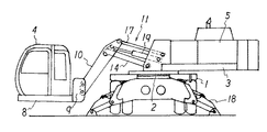
図7は本発明の一実施の形態を示す作業機であり、図8はその要部拡大図である。この作業機はリフトキャブ式のもので、揺動ブラケット33を第1の平行リンク機構34により旋回体3に前後方向に揺動可能に支持し、揺動ブラケット33と運転室4の背面のブラケット9との間に第2の平行リンク機構35を設けたものである。
FIG. 7 is a working machine showing an embodiment of the present invention, and FIG. 8 is an enlarged view of a main part thereof. This working machine is of the lift cab type, and the
第1の平行リンク機構34は、前リンク44と後リンク47と駆動装置としての油圧シリンダ49とを有する。前リンク44と後リンク47は旋回体3にピン42、45により連結し、揺動ブラケット33とピン43、46により連結する。油圧シリンダ49は旋回体3にピン50により連結し、前リンク44に設けたブラケット51にピン52により連結する。
The first
第2の平行リンク機構35は、下リンク54と上リンク57と駆動装置としての油圧シリンダ59とを有する。下リンク54と上リンク57は揺動ブラケット33にピン43、55により連結し、運転室4側のブラケット9にピン53、56により連結する。油圧シリンダ59は揺動ブラケット33にピン55により連結し、下リンク54に設けたブラケット61にピン62により連結する。
The second
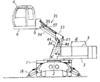
この作業機は、例えばスクラップ処理において、スクラップの視界を良好にして作業するため、あるいは掘削における掘削穴や掘削溝等の内部の目視を良好にするため、図7のように運転室4を高くして作業を行なう。また、運転室4を高くする必要がない場合は、図9に示すように、第1の平行リンク機構34を最後傾状態にし、第2の平行リンク機構35を最も最下傾斜状態にして運転室4を旋回体3上に載置する。
In order to improve the visibility of the scrap, for example, in scrap processing, or to make the inside of the excavation hole, the excavation groove, and the like good in excavation, the working machine has a
一方、オペレータ等が運転室に乗降する際には、図10に示すように、第1の平行リンク機構34を最前傾状態にし、第2の平行リンク機構35は最下傾斜状態にして、オペレータ等が地上で運転室4に乗降可能な搭乗姿勢とする。
On the other hand, when an operator or the like gets on and off the cab, as shown in FIG. 10, the first
このように、この実施の形態においても、運転室4を搭乗姿勢が可能な構成とすることにより、オペレータ等は地上で労力少なく安全に乗降できる。また、足が不自由な人でも運転室4に乗降可能となる。
Thus, also in this embodiment, the operator can get on and off safely on the ground with less labor by configuring the
図11はこの作業機の油圧回路、図12はその安全回路である。これらの回路においても、図5に示した運転室4の方向検出手段としてのリミットスイッチL1と、図8に示す第1の平行リンク機構34の最後傾状態を検出するリミットスイッチL2(第1の姿勢検出手段)と、さらに図8に示す油圧シリンダ59の最伸状態を検出するリミットスイッチL3(第2の姿勢検出手段)を用いる。図11において、75は電磁操作式の油圧シリンダ59のコントロール弁である。
FIG. 11 shows a hydraulic circuit of this working machine, and FIG. 12 shows its safety circuit. Also in these circuits, the limit switch L1 as the direction detecting means for the
この実施の形態においては、運転室4が横向きであって、リミットスイッチL1が閉じてリレーR1が付勢されて常開接点r1が閉じ、かつ第2の平行リンク機構35が最下傾斜状態であり、リミットスイッチL3が閉じてリレーR4が付勢されて常開接点r4が閉じている状態において、オペレータ等は、スイッチS1を操作することによってパイロット弁66を切換え、コントロール弁65を切換えて油圧シリンダ49を伸縮させ、第1の平行リンク機構34を作動させることができる。なお、このとき、運転室4が横向きで第2の平行リンク機構35が最下傾斜状態であることを表示する運転室4内のランプP1が点灯する。
In this embodiment, the
このように、運転室4を搭乗姿勢にするときには、運転室4が横向きで第2の平行リンク機構35が搭乗姿勢を取りうる最下傾斜状態である場合に限ることにより、運転室4が斜め向きあるいは縦向きとなっているときに平行リンク機構34を作動させた場合に運転室4の底面が走行体1等に衝突することを防止することができ、安全性を向上させることができる。
As described above, when the
また、運転室4が横向きであり、かつ第2の平行リンク機構35が最下傾斜状態であるときのみに第1の平行リンク機構34の作動を許容するようにしたので、搭乗姿勢を容易、確実にとることができる。
Further, since the operation of the first
また、本実施の形態においては、第1の平行リンク機構34が最後傾状態にあり、リミットスイッチL2が閉じ、リレーR2が付勢されて常開接点r2が閉じているときにのみ、運転室4内のランプP2が点灯し、また、オペレータ等はスイッチS3の操作によりソレノイド75aまたは75bに通電してコントロール弁75を切換え、油圧シリンダ59を作動させ、第2の平行リンク機構35を上下に揺動させることができる。
In the present embodiment, only when the first
このように、第1の平行リンク機構34が最後傾状態にあるときにのみ第2の平行リンク機構35の作動を可能にしたので、運転室4が旋回体3より前方に突出した状態での運転室4の上下動が防止され、運転室4の移動における障害物との衝突を防止することができ、安全性を確保することができる。
Thus, since the operation of the second
なお、本実施の形態においても、第1の平行リンク機構34が最後傾状態にあるときにリミットスイッチL2が閉じてリレーR2が付勢され、常閉接点r2が開くと、ソレノイド74aへの通電が停止するので、ゲートロック弁74が連通状態になり、旋回装置2、作業用フロント2、アウトリガー18の作動が可能となる。
Also in this embodiment, when the first
また、禁止解除スイッチS2を閉じることにより、リレーR3が付勢され、常開接点r3が閉じるため、スイッチS1、S3の操作により油圧シリンダ49、59の作動が可能となり、また、常閉接点r3が開くことにより、旋回装置2、作業用フロント2、アウトリガー18の作動が可能となる。
Further, by closing the prohibition release switch S2, the relay R3 is energized and the normally open contact r3 is closed, so that the
本発明を実施する場合、油圧シリンダ19、49、59の代わりに油圧モータを用いることができる。また、方向検出手段や姿勢検出手段としてはリミットスイッチ以外に近接スイッチ等他のスイッチを用いることができる。また、平行リンク機構の駆動装置として設ける油圧シリンダ19、49、59は、平行リンク機構を揺動させればよいので、その取付け位置は、上記実施の形態に限定されない。
When the present invention is implemented, a hydraulic motor can be used in place of the
1:走行体、2:旋回装置、3:旋回体、4:運転室、5:パワーユニット、6:作業用フロント、7:リフティングマグネット、8:基枠、9:ブラケット、10:アーム、11:平行リンク機構、14:前リンク、17:後リンク、19:油圧シリンダ、33:揺動ブラケット、34:第1の平行リンク機構、35;第2の平行リンク機構、44:前リンク、47:後リンク、49:油圧シリンダ、54:下リンク、57:上リンク、59:油圧シリンダ、64A〜64C:油圧ポンプ、65:コントロール弁、66;パイロット弁、67:コントロール弁群、68〜73:パイロット弁、74:ゲートロック弁、75:コントロール弁、77:ストライカ、L1〜L3:リミットスイッチ、P1、P2:ランプ、R1〜R4:リレー、S1〜S3:スイッチ 1: traveling body, 2: turning device, 3: turning body, 4: cab, 5: power unit, 6: front for work, 7: lifting magnet, 8: base frame, 9: bracket, 10: arm, 11: Parallel link mechanism, 14: front link, 17: rear link, 19: hydraulic cylinder, 33: swing bracket, 34: first parallel link mechanism, 35; second parallel link mechanism, 44: front link, 47: Rear link, 49: hydraulic cylinder, 54: lower link, 57: upper link, 59: hydraulic cylinder, 64A to 64C: hydraulic pump, 65: control valve, 66; pilot valve, 67: control valve group, 68-73: Pilot valve, 74: gate lock valve, 75: control valve, 77: striker, L1 to L3: limit switch, P1, P2: lamp, R1 to R4: relay, 1~S3: switch
Claims (2)
前記旋回体上に、第1の平行リンク機構を介して前後方向に揺動可能に設けた揺動ブラケットと、
前記第1の平行リンク機構の駆動装置と、
前記運転室の背面に設けたブラケットと前記揺動ブラケットとの間に設けた第2の平行リンク機構と、
前記第2の平行リンク機構の駆動装置とを備え、
前記第1の平行リンク機構が最前傾状態にあり、かつ前記第2の平行リンク機構が最下傾斜状態にあるときに、前記運転室が地上で人が乗降可能な搭乗姿勢となる構成を有すると共に、
前記運転室が走行体に対して横向きであるか否かを検出する方向検出手段と、
前記方向検出手段により運転室が横向きでない状態が検出されているときに前記第1の平行リンク機構の駆動装置の作動を禁止する動作制限手段と、
前記第1の平行リンク機構が最後傾状態であるか否かを検出する第1の姿勢検出手段と、
前記第1の姿勢検出手段により第1の平行リンク機構が最後傾状態でないときに少なくとも前記旋回体の旋回および作業用フロントの作動を禁止する動作制限手段とを備えた
ことを特徴とする作業機。 In a working machine that is provided with a cab in the swivel body and is equipped with a work front,
A swing bracket provided on the swivel body so as to be swingable in the front-rear direction via a first parallel link mechanism;
A driving device for the first parallel link mechanism;
A second parallel link mechanism provided between the bracket provided on the back surface of the cab and the swing bracket;
A drive device for the second parallel link mechanism,
Said first parallel link mechanism is in maximum forward inclination state, and when said second parallel link mechanism is in the lowest inclined position, it has a configuration in which the cab is human on earth is getting on and off can be riding posture With
Direction detecting means for detecting whether or not the driver's cab is lateral to the traveling body;
An operation limiting means for prohibiting the operation of the drive device of the first parallel link mechanism when a state in which the cab is not in the horizontal direction is detected by the direction detection means;
First posture detecting means for detecting whether or not the first parallel link mechanism is in the last tilt state;
A work machine comprising: an operation restriction means for prohibiting at least turning of the revolving body and operation of the work front when the first parallel link mechanism is not in the final tilted state by the first posture detecting means. .
前記第2の平行リンク機構が最下傾斜状態であるか否かを検出する第2の姿勢検出手段をさらに備え、
前記第2の姿勢検出手段により前記最下傾斜状態でない状態が検出されているときに前記第1の平行リンク機構の作動を禁止する動作制限手段をさらに備えると共に、
前記第1の姿勢検出手段が第1の平行リンク機構が最後傾状態でないことを検出しているときに前記第2の平行リンク機構の作動を禁止する動作制限手段をさらに備えた
ことを特徴とする作業機。 The working machine according to claim 1 ,
A second posture detecting means for detecting whether or not the second parallel link mechanism is in a lowest inclined state;
And further comprising an operation restricting means for prohibiting the operation of the first parallel link mechanism when the second posture detecting means detects a state that is not the lowest inclined state.
The first posture detecting means further comprises an operation restricting means for prohibiting the operation of the second parallel link mechanism when the first parallel link mechanism detects that the first parallel link mechanism is not in the final tilt state. Working machine.
Priority Applications (1)
| Application Number | Priority Date | Filing Date | Title |
|---|---|---|---|
| JP2005185117A JP4514656B2 (en) | 2005-06-24 | 2005-06-24 | Working machine |
Applications Claiming Priority (1)
| Application Number | Priority Date | Filing Date | Title |
|---|---|---|---|
| JP2005185117A JP4514656B2 (en) | 2005-06-24 | 2005-06-24 | Working machine |
Publications (3)
| Publication Number | Publication Date |
|---|---|
| JP2007001469A JP2007001469A (en) | 2007-01-11 |
| JP2007001469A5 JP2007001469A5 (en) | 2007-07-12 |
| JP4514656B2 true JP4514656B2 (en) | 2010-07-28 |
Family
ID=37687448
Family Applications (1)
| Application Number | Title | Priority Date | Filing Date |
|---|---|---|---|
| JP2005185117A Expired - Fee Related JP4514656B2 (en) | 2005-06-24 | 2005-06-24 | Working machine |
Country Status (1)
| Country | Link |
|---|---|
| JP (1) | JP4514656B2 (en) |
Cited By (1)
| Publication number | Priority date | Publication date | Assignee | Title |
|---|---|---|---|---|
| CN105781429A (en) * | 2016-04-05 | 2016-07-20 | 英联鑫博(天津)机械制造有限公司 | Counterweight device of rotary drilling rig and rotary drilling rig with same |
Families Citing this family (7)
| Publication number | Priority date | Publication date | Assignee | Title |
|---|---|---|---|---|
| EP2319995B1 (en) | 2009-11-06 | 2012-10-03 | Caterpillar, Inc. | Apparatus for moving a platform |
| CN101830391B (en) * | 2010-06-07 | 2012-02-15 | 三一集团有限公司 | Lifting appliance and front handling mobile crane with same |
| JP6135149B2 (en) * | 2013-01-24 | 2017-05-31 | コベルコ建機株式会社 | Work machine |
| CN103241662B (en) * | 2013-04-03 | 2016-04-06 | 大连理工大学 | A kind of wheel crane |
| JP6719823B2 (en) * | 2016-09-21 | 2020-07-08 | 日本車輌製造株式会社 | Tubing equipment |
| WO2019236892A1 (en) * | 2018-06-07 | 2019-12-12 | Maxon Industries, Inc. | Swing arm liftgate |
| JP7141990B2 (en) * | 2019-09-25 | 2022-09-26 | 日立建機株式会社 | excavator |
Citations (3)
| Publication number | Priority date | Publication date | Assignee | Title |
|---|---|---|---|---|
| JPS5086101A (en) * | 1973-12-01 | 1975-07-11 | ||
| JP2002104795A (en) * | 2000-10-02 | 2002-04-10 | Hitachi Constr Mach Co Ltd | Emergency escaping device for lift cab |
| JP2004332442A (en) * | 2003-05-09 | 2004-11-25 | Komatsu Ltd | Working unit interference preventing region display device for working machine |
-
2005
- 2005-06-24 JP JP2005185117A patent/JP4514656B2/en not_active Expired - Fee Related
Patent Citations (3)
| Publication number | Priority date | Publication date | Assignee | Title |
|---|---|---|---|---|
| JPS5086101A (en) * | 1973-12-01 | 1975-07-11 | ||
| JP2002104795A (en) * | 2000-10-02 | 2002-04-10 | Hitachi Constr Mach Co Ltd | Emergency escaping device for lift cab |
| JP2004332442A (en) * | 2003-05-09 | 2004-11-25 | Komatsu Ltd | Working unit interference preventing region display device for working machine |
Cited By (1)
| Publication number | Priority date | Publication date | Assignee | Title |
|---|---|---|---|---|
| CN105781429A (en) * | 2016-04-05 | 2016-07-20 | 英联鑫博(天津)机械制造有限公司 | Counterweight device of rotary drilling rig and rotary drilling rig with same |
Also Published As
| Publication number | Publication date |
|---|---|
| JP2007001469A (en) | 2007-01-11 |
Similar Documents
| Publication | Publication Date | Title |
|---|---|---|
| JP4514656B2 (en) | Working machine | |
| JP2007001469A5 (en) | ||
| JP4699869B2 (en) | Construction machinery | |
| JP4597914B2 (en) | Work machine | |
| JP4648963B2 (en) | Working unit structure | |
| JP3898111B2 (en) | Work machine | |
| JP6539630B2 (en) | Small turning type hydraulic shovel | |
| JP2001348183A (en) | Ladder for lifting work machine | |
| JP2004131006A (en) | Movable cabin type working machine | |
| JP4746642B2 (en) | Working unit structure | |
| JP4173421B2 (en) | Lifting device for construction machinery | |
| JP4648962B2 (en) | Working unit structure | |
| JP5026948B2 (en) | Construction machinery | |
| JP3235819B2 (en) | Work machine with lifting cab | |
| JP6979040B2 (en) | Cab movable work machine | |
| JPH0745655Y2 (en) | Locking device for hydraulic excavator | |
| JP2010112096A (en) | Turning-lock device of construction machine | |
| JPS5819825B2 (en) | Shovel loader Tenboushisouchi | |
| JP6978402B2 (en) | Cab movable work machine | |
| JP2010216157A (en) | Work machine | |
| JPH0720206Y2 (en) | Revolving work machine with lifting ladder | |
| KR200204146Y1 (en) | A tilting lever for cab of a truck | |
| JP2004262303A (en) | Working vehicle | |
| JP2532824Y2 (en) | Attitude control device for gripping device | |
| JP2003206552A (en) | Crawler construction machinery |
Legal Events
| Date | Code | Title | Description |
|---|---|---|---|
| A521 | Request for written amendment filed |
Free format text: JAPANESE INTERMEDIATE CODE: A523 Effective date: 20070525 |
|
| A621 | Written request for application examination |
Free format text: JAPANESE INTERMEDIATE CODE: A621 Effective date: 20070525 |
|
| A977 | Report on retrieval |
Free format text: JAPANESE INTERMEDIATE CODE: A971007 Effective date: 20100129 |
|
| A131 | Notification of reasons for refusal |
Free format text: JAPANESE INTERMEDIATE CODE: A131 Effective date: 20100202 |
|
| A521 | Request for written amendment filed |
Free format text: JAPANESE INTERMEDIATE CODE: A523 Effective date: 20100402 |
|
| TRDD | Decision of grant or rejection written | ||
| A01 | Written decision to grant a patent or to grant a registration (utility model) |
Free format text: JAPANESE INTERMEDIATE CODE: A01 Effective date: 20100511 |
|
| A01 | Written decision to grant a patent or to grant a registration (utility model) |
Free format text: JAPANESE INTERMEDIATE CODE: A01 |
|
| A61 | First payment of annual fees (during grant procedure) |
Free format text: JAPANESE INTERMEDIATE CODE: A61 Effective date: 20100511 |
|
| R150 | Certificate of patent or registration of utility model |
Ref document number: 4514656 Country of ref document: JP Free format text: JAPANESE INTERMEDIATE CODE: R150 Free format text: JAPANESE INTERMEDIATE CODE: R150 |
|
| FPAY | Renewal fee payment (event date is renewal date of database) |
Free format text: PAYMENT UNTIL: 20130521 Year of fee payment: 3 |
|
| FPAY | Renewal fee payment (event date is renewal date of database) |
Free format text: PAYMENT UNTIL: 20140521 Year of fee payment: 4 |
|
| LAPS | Cancellation because of no payment of annual fees |