JP4510913B2 - Vehicle seat belt device - Google Patents
Vehicle seat belt device Download PDFInfo
- Publication number
- JP4510913B2 JP4510913B2 JP2008322381A JP2008322381A JP4510913B2 JP 4510913 B2 JP4510913 B2 JP 4510913B2 JP 2008322381 A JP2008322381 A JP 2008322381A JP 2008322381 A JP2008322381 A JP 2008322381A JP 4510913 B2 JP4510913 B2 JP 4510913B2
- Authority
- JP
- Japan
- Prior art keywords
- lock
- belt reel
- vehicle
- drive motor
- webbing
- Prior art date
- Legal status (The legal status is an assumption and is not a legal conclusion. Google has not performed a legal analysis and makes no representation as to the accuracy of the status listed.)
- Active
Links
- 230000007246 mechanism Effects 0.000 claims description 55
- 238000004804 winding Methods 0.000 claims description 16
- 238000001514 detection method Methods 0.000 claims description 15
- 230000008859 change Effects 0.000 claims description 14
- 230000001133 acceleration Effects 0.000 description 43
- 210000000078 claw Anatomy 0.000 description 21
- 238000000034 method Methods 0.000 description 19
- 230000008569 process Effects 0.000 description 19
- 230000002093 peripheral effect Effects 0.000 description 5
- 230000005540 biological transmission Effects 0.000 description 3
- 238000010586 diagram Methods 0.000 description 2
- 230000000452 restraining effect Effects 0.000 description 2
- 230000000630 rising effect Effects 0.000 description 2
- 210000001015 abdomen Anatomy 0.000 description 1
- 230000009471 action Effects 0.000 description 1
- 230000004913 activation Effects 0.000 description 1
- 238000004891 communication Methods 0.000 description 1
- 230000003111 delayed effect Effects 0.000 description 1
- 230000000694 effects Effects 0.000 description 1
- 230000001960 triggered effect Effects 0.000 description 1
Images


Classifications
-
- B—PERFORMING OPERATIONS; TRANSPORTING
- B60—VEHICLES IN GENERAL
- B60R—VEHICLES, VEHICLE FITTINGS, OR VEHICLE PARTS, NOT OTHERWISE PROVIDED FOR
- B60R22/00—Safety belts or body harnesses in vehicles
- B60R22/32—Devices for releasing in an emergency, e.g. after an accident ; Remote or automatic unbuckling devices
- B60R22/321—Devices for releasing in an emergency, e.g. after an accident ; Remote or automatic unbuckling devices using electric means
-
- B—PERFORMING OPERATIONS; TRANSPORTING
- B60—VEHICLES IN GENERAL
- B60R—VEHICLES, VEHICLE FITTINGS, OR VEHICLE PARTS, NOT OTHERWISE PROVIDED FOR
- B60R21/00—Arrangements or fittings on vehicles for protecting or preventing injuries to occupants or pedestrians in case of accidents or other traffic risks
- B60R21/01—Electrical circuits for triggering passive safety arrangements, e.g. airbags, safety belt tighteners, in case of vehicle accidents or impending vehicle accidents
- B60R21/013—Electrical circuits for triggering passive safety arrangements, e.g. airbags, safety belt tighteners, in case of vehicle accidents or impending vehicle accidents including means for detecting collisions, impending collisions or roll-over
- B60R21/0132—Electrical circuits for triggering passive safety arrangements, e.g. airbags, safety belt tighteners, in case of vehicle accidents or impending vehicle accidents including means for detecting collisions, impending collisions or roll-over responsive to vehicle motion parameters, e.g. to vehicle longitudinal or transversal deceleration or speed value
-
- B—PERFORMING OPERATIONS; TRANSPORTING
- B60—VEHICLES IN GENERAL
- B60R—VEHICLES, VEHICLE FITTINGS, OR VEHICLE PARTS, NOT OTHERWISE PROVIDED FOR
- B60R21/00—Arrangements or fittings on vehicles for protecting or preventing injuries to occupants or pedestrians in case of accidents or other traffic risks
- B60R21/01—Electrical circuits for triggering passive safety arrangements, e.g. airbags, safety belt tighteners, in case of vehicle accidents or impending vehicle accidents
- B60R2021/01204—Actuation parameters of safety arrangents
- B60R2021/01252—Devices other than bags
- B60R2021/01265—Seat belts
- B60R2021/01272—Belt tensioners
-
- B—PERFORMING OPERATIONS; TRANSPORTING
- B60—VEHICLES IN GENERAL
- B60R—VEHICLES, VEHICLE FITTINGS, OR VEHICLE PARTS, NOT OTHERWISE PROVIDED FOR
- B60R21/00—Arrangements or fittings on vehicles for protecting or preventing injuries to occupants or pedestrians in case of accidents or other traffic risks
- B60R21/01—Electrical circuits for triggering passive safety arrangements, e.g. airbags, safety belt tighteners, in case of vehicle accidents or impending vehicle accidents
- B60R21/013—Electrical circuits for triggering passive safety arrangements, e.g. airbags, safety belt tighteners, in case of vehicle accidents or impending vehicle accidents including means for detecting collisions, impending collisions or roll-over
- B60R21/0132—Electrical circuits for triggering passive safety arrangements, e.g. airbags, safety belt tighteners, in case of vehicle accidents or impending vehicle accidents including means for detecting collisions, impending collisions or roll-over responsive to vehicle motion parameters, e.g. to vehicle longitudinal or transversal deceleration or speed value
- B60R2021/01327—Angular velocity or angular acceleration
Description
この発明は、シートに着座した乗員をウェビングによって拘束する車両のシートベルト装置に関するものである。 The present invention relates to a vehicle seat belt device that restrains an occupant seated on a seat by webbing.
車両のシートベルト装置として、緊急時に車両挙動が不安定になったときに、ウェビングの引き出しを機械的にロックする緊急ロック機構を備えたものが知られている。 2. Description of the Related Art As a vehicle seat belt device, there is known a vehicle equipped with an emergency lock mechanism that mechanically locks a webbing drawer when vehicle behavior becomes unstable in an emergency.
この緊急ロック機構は、ウェビングを巻回するベルトリールの側部に、ベルトリールとの間に所定以上のトルクが作用したときに相対回転するロック作動ドラムと、ベルトリールとロック作動ドラムが一方向に相対回転したときにケーシングのロック溝と噛合するロック爪とが設けられている。さらに、ロック作動ドラムに近接した位置には車両が不安定状態であるとき(例えば、車両に所定量以上の加速度が作用した場合や、車両が所定量以上傾斜したとき)に作動する緊急作動部が設けられ、緊急作動部の作動によってロック作動ドラムに制動力が作用するようになっている。
このため、車両挙動が不安定になって緊急作動部が作動すると、ロック作動ドラムが制動され、ウェビングが引き出されようとしたときに、ベルトリールとロック作動ドラムが一方向に相対回転する。これにより、ロック爪がケーシングのロック溝と噛合し、その結果、ベルトリールのウェビング引き出し方向の回転がロックされる。
また、緊急ロック機構がロック作動した後に、ウェビングの引き出し方向の力が無くなりベルトリールが戻しばねの力によって巻取り方向に回転すると、ベルトリールとロック作動ドラムが他方向に所定量相対回転したところで、ロック爪とロック溝の噛合が自動的に解除される。
This emergency lock mechanism has a lock actuating drum that rotates relative to the side of the belt reel around which the webbing is wound when a predetermined torque or more acts between the belt reel and the belt reel and the lock actuating drum in one direction. And a locking claw that meshes with the locking groove of the casing when rotated relative to the casing. Further, an emergency operation unit that operates when the vehicle is in an unstable state at a position close to the lock operation drum (for example, when an acceleration of a predetermined amount or more is applied to the vehicle or the vehicle is inclined by a predetermined amount or more). The braking force is applied to the lock operation drum by the operation of the emergency operation unit.
For this reason, when the vehicle behavior becomes unstable and the emergency operation unit operates, the lock operation drum is braked, and when the webbing is about to be pulled out, the belt reel and the lock operation drum rotate relative to each other in one direction. Thereby, the lock claw meshes with the lock groove of the casing, and as a result, the rotation of the belt reel in the webbing pull-out direction is locked.
Also, after the emergency locking mechanism is locked, if the webbing pull-out force is lost and the belt reel rotates in the winding direction by the force of the return spring, the belt reel and the locking drum are rotated relative to each other by a predetermined amount. The engagement between the lock claw and the lock groove is automatically released.
ところで、近年、車両のシートベルト装置として、戻しばねの巻取り補助や、車両状態に応じた乗員拘束のために、駆動モータをベルトリールに接続したものが知られている(例えば、特許文献1参照)。
この駆動モータを備えた従来のシートベルト装置においては、シートベルトのバックルを外したことや、車両状態の変化を検出したことを契機として駆動モータを駆動させるものであるため、機械的に独立して作動する緊急ロック機構のロック解除に対しては駆動モータは直接的に関与しない。緊急ロック機構は、通常は、不安定状態が解消された時点で戻しばねの力によって自動的にロック解除されるが、例えば、以下の(1),(2)の状況では自動的なロック解除が難しくなる。 In the conventional seat belt device provided with this drive motor, the drive motor is driven when the seat belt buckle is removed or a change in the vehicle state is detected. The drive motor is not directly involved in the unlocking of the emergency locking mechanism that operates. The emergency lock mechanism is normally automatically unlocked by the force of the return spring when the unstable state is resolved. For example, in the following situations (1) and (2), automatic unlocking is performed automatically. Becomes difficult.
(1)車両の急激な加速時や凹凸路走行時に、緊急ロック機構が作動し、かつ、乗員の上体が大きく変動している間にウェビングが戻しばねによって一気に若しくは徐々に巻き取られたときに、乗員に対するウェビングの引き込み代が殆ど残っていない場合。
すなわち、車両が安定状態に戻ったときに、締め込みによる乗員からの反力が大きく、戻しばねによる自動的なロック解除ができない場合。
この場合には、ウェビングのロックが自動的には外れないため、乗員が一度バックルを外さなければならない。
(1) When the emergency lock mechanism is activated during sudden acceleration of the vehicle or traveling on uneven roads, and the webbing is wound up at once or gradually by the return spring while the upper body of the occupant is largely fluctuating In addition, when there is almost no remaining webbing allowance for the occupant.
That is, when the vehicle returns to a stable state, the reaction force from the occupant due to tightening is large, and automatic unlocking by the return spring cannot be performed.
In this case, the webbing lock cannot be removed automatically, so the passenger must remove the buckle once.
(2)カーブや曲がり角をある程度以上のスピードで走行中に、緊急ロック機構がロック作動したときに、その後に乗員の上体が弱い遠心力を受けて緩やかに動く場合や、乗員が自分の意思で上体を動かそうとした場合。
この場合には、本来、ウェビングによる拘束がない方が快適な運転を行うことができるのにも拘わらず不要な拘束力が乗員に作用するため、乗員に不快感や操作のし難さを感じさせる。
(2) When the emergency lock mechanism is activated while driving at a speed exceeding a certain level on a curve or corner, the upper body of the occupant may move slowly due to weak centrifugal force, or the occupant may When trying to move the upper body.
In this case, although the driver is not restrained by the webbing, the driver can feel comfortable and the driver feels uncomfortable and difficult to operate because unnecessary restraint force acts on the passenger. Let
そこでこの発明は、緊急ロック機構が一度作動した後の不要なロック作動の継続が解除されるようにして、快適性の向上と車両操作性の向上を図ることのできる車両のシートベルト装置を提供しようとするものである。 Accordingly, the present invention provides a vehicle seat belt device capable of improving comfort and vehicle operability by releasing the continuation of unnecessary lock operation after the emergency lock mechanism is once operated. It is something to try.
上記の課題を解決する請求項1に記載の発明は、ウェビングを巻回したベルトリール(例えば、後述の実施形態におけるベルトリール12)と、このベルトリールを巻取り方向に常時付勢する付勢手段(例えば、後述の実施形態における図示しない戻しばね)と、車両挙動が不安定になったときに、前記ベルトリールのウェビング引き出し方向の回転を機械的にロックし、前記ベルトリールのウェビング巻取り方向の所定量以上の回転によってロックが自動的に解除される緊急ロック機構(例えば、後述の実施形態における緊急ロック機構22)と、前記ベルトリールに回転駆動力を付与する駆動モータ(例えば、後述の実施形態における駆動モータ10)と、前記駆動モータを制御する制御手段(例えば、後述の実施形態におけるコントローラ21)と、を備えた車両のシートベルト装置において、前記ベルトリールの回転位置を検出する回転位置検出手段(例えば、後述の実施形態における回転センサ11)と、車両状態を検出する車両状態検出手段(例えば、後述の実施形態における前後加速度センサ16)と、前記駆動モータへの非通電時に、車両状態検出手段によって検出される車両状態と前記回転位置検出手段によって検出されるベルトリールの回転位置の変化に基づいて、前記緊急ロック機構の作動後にロック状態が継続しているか否かを判定するロック継続判定手段(例えば、後述の実施形態におけるロック継続判定手段41)と、を設け、前記制御手段は、前記ロック継続判定手段が所定時間以上ロック状態の継続を判定したときに、前記駆動モータをロック解除方向に回転駆動させるとともに、ロック解除を行うための前記駆動モータの駆動開始時間を、前記ロック継続判定手段による判定中の車速に応じ、車速が速くなるに従って遅くなるように調整することを特徴とする。
これにより、駆動モータが非通電状態のときに、緊急ロック機構がロック作動する車両の不安定挙動が車両状態検出手段によって検出され、そのときからのベルトリールの回転位置の変化が回転位置検出手段によって検出される。このとき、緊急ロック機構がベルトリールの引き出し方向の回転を機械的にロックしているときには、ベルトリールの巻取り方向の回転が検出されることはあっても、引き出し方向の回転が検出されることはない。したがって、ロック状態の継続は、車両状態検出手段と回転位置検出手段の信号に基づいて判定することができる。本来ロック状態が継続されているはずのない所定時間以上ロック継続判定手段によってロック状態の継続判定が続く場合には、制御手段が駆動モータを回転駆動することで緊急ロック機構によるロックが強制的に解除される。
また、ロック解除のための駆動モータの駆動開始時間は、ロック継続判定中の走行状態に応じて調整され、例えば、連続したカーブを走行しているときに、ロック継続判定中の走行速度が高い場合には、駆動モータのロック解除のための駆動開始時間を遅らせる。これにより、連続したカーブを高速で走行した場合にも、緊急ロック機構が頻繁に作動と解除を繰り返す可能性が少なくなる。
The invention according to claim 1, which solves the above problem, is a belt reel (for example, a
Thereby, when the drive motor is in a non-energized state, the unstable behavior of the vehicle in which the emergency lock mechanism is locked is detected by the vehicle state detecting means, and the change in the rotational position of the belt reel from that time is detected as the rotational position detecting means. Detected by. At this time, when the emergency lock mechanism mechanically locks the rotation of the belt reel in the pulling direction, the rotation in the pulling direction is detected even though the rotation of the belt reel in the winding direction is detected. There is nothing. Therefore, the continuation of the locked state can be determined based on the signals of the vehicle state detecting means and the rotational position detecting means. When the lock continuation determination means continues the lock state continuation determination for a predetermined time or longer that the lock state should not have been continued, the control means forcibly locks the emergency lock mechanism by driving the drive motor to rotate. Canceled.
Further, the drive start time of the drive motor for unlocking is adjusted according to the running state during the lock continuation determination. For example, when traveling on a continuous curve, the running speed during the lock continuation determination is high. In this case, the drive start time for unlocking the drive motor is delayed. As a result, even when the vehicle travels at a high speed on a continuous curve, the emergency lock mechanism is less likely to be repeatedly activated and released.
請求項2に記載の発明は、ウェビングを巻回したベルトリールと、このベルトリールを巻取り方向に常時付勢する付勢手段と、車両挙動が不安定になったときに、前記ベルトリールのウェビング引き出し方向の回転を機械的にロックし、前記ベルトリールのウェビング巻取り方向の所定量以上の回転によってロックが自動的に解除される緊急ロック機構と、前記ベルトリールに回転駆動力を付与する駆動モータと、前記駆動モータを制御する制御手段と、を備えた車両のシートベルト装置において、前記ベルトリールの回転位置を検出する回転位置検出手段と、車両状態を検出する車両状態検出手段と、前記駆動モータへの非通電時に、車両状態検出手段によって検出される車両状態と前記回転位置検出手段によって検出されるベルトリールの回転位置の変化に基づいて、前記緊急ロック機構の作動後にロック状態が継続しているか否かを判定するロック継続判定手段と、を設け、前記制御手段は、前記ロック継続判定手段が所定時間以上ロック状態の継続を判定したときに、前記駆動モータをロック解除方向に回転駆動させるとともに、ロック解除を行うための前記駆動モータの駆動開始時間を、前記ロック継続判定手段による判定中の路面状況に応じて変更することを特徴とする。 According to a second aspect of the present invention, there is provided a belt reel around which the webbing is wound, a biasing means for constantly biasing the belt reel in the winding direction, and the belt reel when the vehicle behavior becomes unstable. An emergency lock mechanism that mechanically locks the rotation in the webbing pull-out direction and automatically releases the lock when the belt reel rotates more than a predetermined amount in the webbing winding direction, and applies a rotational driving force to the belt reel. In a vehicle seat belt apparatus comprising a drive motor and a control means for controlling the drive motor, a rotational position detecting means for detecting a rotational position of the belt reel, a vehicle state detecting means for detecting a vehicle state, The belt state detected by the vehicle state detected by the vehicle state detection means and the rotational position detection means when the drive motor is de-energized Lock continuation determining means for determining whether or not the locked state continues after the emergency lock mechanism is activated based on a change in the rotational position, and the control means is configured such that the lock continuation determining means is not less than a predetermined time. When the continuation of the locked state is determined, the drive motor is driven to rotate in the unlocking direction, and the driving start time of the driving motor for unlocking is set to the road surface condition being determined by the lock continuation determining unit. It is characterized by changing accordingly .
請求項1に記載の発明によれば、ロック継続判定手段によって緊急ロック機構の作動後にロック状態が継続しているか否かを判定し、本来ロック状態が継続されているはずのない所定時間以上継続判定が続く場合に、駆動モータによって緊急ロック機構によるロックを強制的に解除するため、緊急ロック機構の不要なロック継続を抑制して、乗員の快適性と車両の操作性を向上させることができる。
また、請求項1に記載の発明によれば、ロック解除のための駆動モータの駆動開始時間を、ロック継続判定中の車両の走行速度に応じて調整するため、緊急ロック機構の作動と解除の頻繁な繰り返しを抑制することができる。したがって、この発明によれば、乗員に与える不快感や違和感をより少なくすることができる。
According to the first aspect of the present invention, it is determined by the lock continuation determining means whether or not the locked state is continued after the operation of the emergency lock mechanism, and continues for a predetermined time that the locked state should not be continued. When the determination continues, the drive motor forcibly releases the lock by the emergency lock mechanism, so that unnecessary lock continuation of the emergency lock mechanism can be suppressed and passenger comfort and operability of the vehicle can be improved. .
According to the first aspect of the invention, since the drive start time of the drive motor for unlocking is adjusted according to the traveling speed of the vehicle during the lock continuation determination, the emergency lock mechanism is activated and released. Frequent repetition can be suppressed. Therefore, according to this invention, the discomfort and discomfort given to the passenger can be further reduced.
請求項2に記載の発明によれば、ロック解除を行うための駆動モータの駆動開始時間が前記ロック継続判定手段による判定中の路面状況に応じて変更されるため、常に、路面状況に応じて適切にロック解除を実行することができる。 According to the second aspect of the present invention, since the drive start time of the drive motor for releasing the lock is changed according to the road surface condition being determined by the lock continuation determining means, always according to the road surface condition. Unlocking can be performed appropriately.
以下、この発明の各実施形態を図面に基づいて説明する。なお、以下で説明する参考例と各実施形態は制御のみが異なり、機械的な構成は共通とされている。最初に各実施形態で共通する構成について説明する。 Embodiments of the present invention will be described below with reference to the drawings. It should be noted that the reference example described below and each embodiment differ only in control, and have a common mechanical configuration. First, a configuration common to the embodiments will be described.
図1は、この発明にかかるシートベルト装置1の全体概略構成を示すものであり、同図中2は、乗員3の着座するシートである。この実施形態のシートベルト装置1は、所謂三点式のシートベルト装置であり、図示しないセンタピラーに取付けられたリトラクタ4からウェビング5が上方に引き出され、そのウェビング5がセンタピラーの上部側に支持されたスルーアンカ6に挿通されるとともに、ウェビング5の先端がシート2の車室外側寄りのアウタアンカ7を介して車体フロアに固定されている。そして、ウェビング5のスルーアンカ6とアウタアンカ7の間にはタングプレート8が挿通されており、そのタングプレート8は、シート2の車体内側寄りの車体フロアに固定されたバックル9に対して脱着可能となっている。
FIG. 1 shows an overall schematic configuration of a seat belt device 1 according to the present invention. In FIG. 1,
ウェビング5は、初期状態ではリトラクタ4に巻き取られており、乗員3が手で引き出してタングプレート8をバックル9に固定することにより、乗員3の主に胸部と腹部をシート2に対して拘束する。また、このシートベルト装置1は、緊急時や車両の挙動変化が大きいときに、電動式の駆動モータ10によって自動的にウェビング5の引き込みを行う。この駆動モータ10による具体的な引き込み制御については説明を省略する。
The
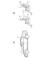
リトラクタ4は、図2に示すようにケーシング14に回転可能に収容されたベルトリール12にウェビング5が巻回されるとともに、ケーシング14の一端側にベルトリール12の軸が突出している。このベルトリール12は、クラッチ20を含む動力伝達機構13を介して駆動モータ10の回転軸10aに連動可能に接続されている。動力伝達機構13は、駆動モータ10の回転を減速してベルトリール12に伝達する。また、リトラクタ4には、ベルトリール12をウェビング巻取り方向に付勢する図示しない戻しばねが設けられ、戻しばねによるウェビング巻取り方向の付勢力がベルトリール12に作用するようになっている。なお、クラッチ20は、モータ10の正転方向(ウェビング巻取り方向)の回転と逆方向(ウェビング引き出し方向)の回転を契機としてオン状態とオフ状態に切り替え操作されるようになっている。
As shown in FIG. 2, the retractor 4 has a
また、リトラクタ4には、ベルトリール12の回転位置を検出する回転センサ11(回転位置検出手段)が設けられている。この回転センサ11は、例えば、円周方向に沿って異磁極が交互に着磁され、ベルトリール12と一体に回転する磁性円板と、この磁性円板の外周縁部に近接配置された一対のホール素子と、ホール素子の検出信号を処理するセンサ回路とから成り、センサ回路で処理されたパルス信号がコントローラ21(制御手段)に出力されるようになっている。
Further, the retractor 4 is provided with a rotation sensor 11 (rotational position detecting means) for detecting the rotational position of the
この場合、ベルトリール12の回転に応じてセンサ回路からコントローラ21に入力されたパルス信号は、ベルトリール12の回転量や、回転速度、回転方向等を検出するのに用いられる。つまり、コントローラ21においては、パルス信号をカウントすることによってベルトリール12の回転量(ウェビング5の引き出し量)を検出し、パルス信号の変化速度(周波数)を演算することによってベルトリール12の回転速度(ウェビング5の巻取り・引き出し速度)を求め、さらに、両パルス信号の波形の立ち上がりの比較によってベルトリール12の回転方向を検出する。
In this case, the pulse signal input from the sensor circuit to the
コントローラ21の入力側には、回転センサ11のほかに、車両の走行速度を検出する車速センサ15と、車両に作用する前後方向の加速度を検出する前後加速度センサ16と、車両に作用する左右方向の加速度を検出する横加速度センサ17と、車両に作用するヨーレートを検出するヨーレートセンサ18と、車輪のスリップ率を求めるために用いる車輪速センサ19と、が接続されている。また、コントローラ21は、車両が不安定状況になったときに、エンジンの出力とブレーキの制動力を統合的に制御して車両の挙動の乱れを抑制するVSA(Vehicle Stability Assist)コントローラとの間で通信が行われるようになっている。なお、この実施形態においては、車速センサ15、前後加速度センサ16、横加速度センサ17、ヨーレートセンサ18、車輪速センサ19は車両状態を検出する車両状態検出手段を構成している。
On the input side of the
また、リトラクタ4には、車両に所定値以上の加速度が作用した場合(車両が不安定になった場合)や、ウェビング5が急激に引き出されようとした場合(ベルトリール12がウェビング引き出し方向に急激に回転しようとした場合)等に、ベルトリール12のウェビング引き出し方向の回転を機械的にロックする緊急ロック機構22が設けられている。
Further, the retractor 4 has an acceleration of a predetermined value or more acting on the vehicle (when the vehicle becomes unstable), or when the
図3は、リトラクタ4に設けられた緊急ロック機構22の詳細を示すものである。
ケーシング14には一対の側壁14A,14Bが設けられ、一方の側壁14Aには、前述した動力伝達機構13と、戻しばねを収容する図示しないスプリングケースとが取り付けられ、他方の側壁14Bには、後述するロック作動ドラム23を支持するリテーナ24が取り付けられている。また、両側の側壁14A,14Bには、略円形の孔25が設けられ、その各孔25の内周に、ウェビング巻取り方向に傾斜したロック溝26が形成されている。
FIG. 3 shows details of the
The
ベルトリール12の軸方向の両側には支持フランジ27A,27Bが設けられ、その各支持フランジ27A,27Bの外周縁部にはロック爪28が揺動可能に取り付けられている。ロック爪28は、先端側が径方向外側に回動して突出したときに、ケーシング14側のロック溝26と噛合する。ロック爪28は、ウェビング巻取り方向に傾斜したロック溝26と噛合することによってベルトリール12の引き出し方向の回転をロックするとともに、ベルトリール12の巻取り方向の回転を許容する。また、各支持フランジ27A,27Bに支持されるロック爪28は連結ピン29によって一体回転可能に連結されている。
また、ベルトリール12の他方側(リテーナ24側)の支持フランジ27Bの軸芯位置にはリール軸12aが突出し、そのリール軸12aにロック作動ドラム23が嵌合されている。ロック作動ドラム23は、リール軸12aに微小な摩擦抵抗を持って嵌合され、ベルトリール12の通常回転時にはベルトリール12と一体に回転し、両者に相反方向の力が加わったとき等には、ベルトリール12に対して設定角度の範囲で相対回動する。
Further, the
ロック作動ドラム23の外周縁部には、連結ピン29の端部が貫通する図示しない長孔が設けられている。そして、ロック作動ドラム23を貫通する連結ピン29の端部には、ロック作動ドラム23のガイド面30に当接するカム片31が設けられている。このカム片31は、ベルトリール12がロック作動ドラム23に対してウェビング引き出し方向に相対回動したときに、ガイド面30による案内作用によって連結ピン29を一方に回転させる。こうして連結ピン29が回転すると、支持フランジ27A,27Bの各ロック爪28を外側に突出させるように回動させる。
A long hole (not shown) through which the end of the connecting
また、ロック作動ドラム23は、外周面に複数のクラッチ歯32が形成されるとともに、軸方向外側の端面にロックアームが33が揺動可能に取り付けられている。ロックアーム33は、遠心力の影響を受ける質量体から成り、ロック作動ドラム23の回転中心から離間した位置に揺動可能に取り付けられている。そして、ロックアーム33は、アーム先端側にロック爪34が設けられ、ロック作動ドラム23の回転に応じた遠心力を受け、ロック爪34側を径方向外側に振り出すようになっている。また、ロック作動ドラム23とロックアーム33の間には、ロックアーム33のロック爪34側を常時ロック作動ドラム23の径方向内側方向に付勢する付勢スプリング35が設けられている。
The
リテーナ24は、ロック作動ドラム23とロックアーム33の前面側と周囲を覆った状態でケーシング14に固定される。リテーナ24には、ベルトトリール12とロック作動ドラム23の軸部を回転自在に支持する図示しない軸受構造が設けられるとともに、ロックアーム33のロック爪34の外周側に臨むように内歯構造の図示しないクラッチ歯が設けられている。このリテーナ24のクラッチ歯は、ロックアーム33が遠心力を受けて径方向外側に揺動したときに、ロックアーム33のロック爪34が噛合する。ロック作動ドラム23はこれによって回転をロックされ、その結果、ベルトリール12との間に相対回転を生じ、前述のようにベルトリール12の両側のロック爪28がケーシング14のロック溝26と噛合されることとなる。したがって、ウェビング5が急激に引き出されようとしたときには、このロックアーム33とリテーナ24のクラッチ歯32を通したロック機構系によってベルトリール12のウェビング引き出し方向の回転がロックされる。以下、このロック機構系を引き出し感応ロック系と呼ぶ。
The
また、リテーナ24内の下部には、車両の加速度を感知して係止爪36を動作させるビークルセンサ37が設けられている。このビークルセンサ37は、センサケース38とセンサキャップ39によって囲われた収容部内にセンサウェイト40が配置され、センサウェイト40に係止爪36が一体に取り付けられている。センサウェイト40は、車両の加速度に応じて揺動し、規定量以上揺動したときに係止爪36をロック作動ドラム23のクラッチ歯32に噛合させる。
こうして、係止爪36がクラッチ歯32に噛合されると、ロック作動ドラム23の回転がロックする。したがって、この状態でウェビング5が引き出されようとすると、ベルトリール12とロック作動ドラム23が相対回転し、その結果、ベルトリール12のロック爪28がケーシング14のロック溝26に噛合し、ベルトリール12のウェビング引き出し方向の回転をロックする。以下、このロック系を車体感応ロック系と呼ぶ。
In addition, a
Thus, when the locking
ここで、前述の引き出し感応ロック系と車体感応ロック系のいずれの場合にも、ベルトリール12のウェビング引き出し方向の回転がロックされた後には、ベルトリール12がウェビング巻取り方向に所定量以上回転操作されたときにロック状態が解除される。すなわち、ロック作動ドラム23の回転が停止した状態で、ベルトリール12がウェビング巻取り方向に回転すると、ベルトリール12とロック作動ドラム23の相対位置関係が初期位置に戻され、その結果、連結ピン29を通してロック爪28が他方に回転することにより、ロック爪28とロック溝26の噛合が解除される。なお、ロック解除のためのベルトリール12のウェビング巻取り方向の操作は基本的には戻しばねの力によって自動的に行われるが、後に説明する特殊な状況では、駆動モータ10の駆動力によって行われる。
Here, in both the drawer-sensitive locking system and the vehicle-body-sensitive locking system, the
また、コントローラ21には、図2に示すように駆動モータ10への非通電時に、センサ15〜19で検出される車両状態と、回転センサ11によって検出されるベルトリール12の回転位置の変化に基づき、緊急ロック機構22のロック作動が継続しているか否かを判定するロック継続判定手段41が設けられている。
In addition, the
ロック継続判定手段41は、前後加速度センサ15や横加速度センサ17の検出値が所定値以上であるときに、緊急ロック機構22がロック作動したものと判断し、このロック作動判断時点のベルトリール12の回転位置を読み込むとともに、それ以降のベルトリール12の回転位置を監視する。そして、このときベルトリール12が引き出し方向に回転した場合にはロックが解除されたものと判定し、ベルトリール12が巻取り方向に回転することがあっても引き出し方向に回転しない場合にはロック状態が継続しているものと判定する。
The lock
<参考例>
この参考例の場合、コントローラ21は、緊急ロック機構22がロック作動する車両状態になった後に、ロック継続判定手段41によるロック継続の判定が所定時間以上つづいたときに、ベルトリール12をウェビング巻取り方向に所定量以上回転させるように駆動モータ10を制御する。
この参考例による制御は、図4に示すような急加速時の状況や、図6に示すような凹凸路走行時の状況を想定している。
<Reference example>
In the case of this reference example , the
The control according to this reference example assumes a situation during sudden acceleration as shown in FIG. 4 and a situation during running on an uneven road as shown in FIG.
図4(A)に示すように車両cが急加速する場合には、図4(B)に示すように乗員mはシートsに急激に押し付けられる。このとき、前後加速度が所定値を超えると、緊急ロック機構22が作動するとともに、乗員mがシートsに押し付けられてウェビング5が一瞬緩む結果、戻しばねの力によってウェビング5がベルトリール12に巻き取られる。
When the vehicle c rapidly accelerates as shown in FIG. 4 (A), the occupant m is suddenly pressed against the seat s as shown in FIG. 4 (B). At this time, if the longitudinal acceleration exceeds a predetermined value, the
図5は、このような状況でのベルトリール12の回転位置の変化を示している。
同図に示すように車両の加速が終了した後にも、以下の(a),(b)のような特殊な状況下では緊急ロック機構22(ELR)がロックしたままとなり易い。
(a)車両の加速が終了した後に、ウェビング5に乗員mの上体荷重等が加わり、戻しばねに抗する張力がウェビング5に作用し続けているとき。
(b)車両の加速が終了した後に、ウェビング5による乗員の締め込みが強く、戻しばねの力でベルトリール12をウェビング巻き取り方向に回転させることができないとき。
したがって、このような状況では、ロック状態が所定時間以上つづいたときに駆動モータ10によって強制的にロック解除を行う。
FIG. 5 shows a change in the rotational position of the
As shown in the figure, even after the acceleration of the vehicle is completed, the emergency lock mechanism 22 (ELR) is likely to remain locked under the special circumstances as shown in (a) and (b) below.
(A) After acceleration of the vehicle is finished, the upper body load of the occupant m is applied to the
(B) When acceleration of the vehicle is finished and the occupant is tightly tightened by the
Therefore, in such a situation, the lock is forcibly released by the
また、図6(A)に示すように車両cが凹凸路を走行する場合には、凹凸を乗り越えるときの衝撃によって緊急ロック機構22が作動するとともに、凹凸を乗り越える毎に乗員の上体が前後左右に振られ、ウェビング5(ベルトリール12)が戻しばねの力によって少しずつ巻締まりを起こす。
図7は、このような状況でのベルトリール12の回転位置の変化を示している。
同図に示すように凹凸走行を終了した後にも、上記の(a),(b)のような特殊な状況下では緊急ロック機構22(ELR)がロックしたままとなり易い。
この場合も、ロック状態が所定時間以上つづいたときに駆動モータ10によって強制的にロック解除を行う。
As shown in FIG. 6A, when the vehicle c travels on an uneven road, the
FIG. 7 shows a change in the rotational position of the
As shown in the figure, the emergency lock mechanism 22 (ELR) is likely to remain locked under the special circumstances such as the above (a) and (b) even after finishing the uneven driving.
Also in this case, the lock is forcibly released by the
以下、この参考例のコントローラ21による制御を図8のフローチャートを基にして説明する。
ステップS101においては、ベルトリール12の回転位置と、車両の前後加速度や横加速度を読み込む。
次の、ステップS102においては、車両の加速度が緊急ロック機構22のロック作動閾値を超えるか否かを判定し、YESの場合には、ステップS103に進み、NOの場合には、ステップS101に戻る。つまり、ここでは、緊急ロック機構22の作動の有無を判定する。
Hereinafter, control by the
In step S101, the rotational position of the
In the next step S102, it is determined whether or not the acceleration of the vehicle exceeds the lock operation threshold value of the
ステップS103においては、ベルトリール12の回転位置を再度読み込み、つづくステップS104においては、緊急ロック機構22のロック作動開始時におけるベルトリール12の回転位置と、現在のベルトリール12の回転位置とを比較し、その結果に基づいてベルトリール12のウェビング引き出し方向の回転があったか否かを判定する。
ステップS104において、YESの場合には、ステップS101に戻り、NOの場合には、ステップS105に進む。
ステップS105においては、ベルトリール12のウェビング引き出し方向の回転なしとの判定が所定時間以上継続したか否かを判定し、ここでYESの場合には、次のステップS106に進み、NOの場合には、ステップS104に戻る。
In step S103, the rotational position of the
If YES in step S104, the process returns to step S101. If NO, the process proceeds to step S105.
In step S105, it is determined whether or not the determination that there is no rotation in the webbing pull-out direction of the
ステップS106においては、駆動モータ10をウェビング巻取り方向に駆動し、つづく、ステップS107においては、ベルトリール12がロックを解除し得る所定量以上回転しているか否かを判定する。
ステップS107でYESの場合には、リターンし、NOの場合には、ステップS106へと戻る。つまり、ここではベルトリール12が所定量以上回転してロックが解除されるまで駆動モータ10の通電がつづけられる。ただし、所定時間駆動モータ10の通電がつづけられても、ベルトリール12が所定量以上回転しないときには警告を出して駆動モータの通電を停止する。
なお、ステップS107でYESの場合には、さらに、ベルトリール12が引き出し方向に所定量以上回転したか否かを確認し、所定量以上回転していない場合に、駆動モータ10による巻取りを再度行うようにしても良い。
In step S106, the
If YES in step S107, the process returns. If NO, the process returns to step S106. That is, here, the
If YES in step S107, it is further checked whether or not the
したがって、この参考例のシートベルト装置においては、ロック継続判定手段41によって緊急ロック機構22の作動後にロック状態が所定時間以上継続しているか否かを判定し、所定時間以上ロック状態が継続している場合に、駆動モータ10によって緊急ロック機構22によるロックを強制的に解除するため、拘束の不要な状況下でのウェビング5による乗員拘束を無くし、乗員に不快感や違和感を与えたり、さらに運転操作を制限する不具合を無くすことができる。
Therefore, in the seat belt device of this reference example , the lock
<第1の実施形態>
この実施形態の場合、コントローラ21は、緊急ロック機構22がロック作動する車両状態になった後に、ロック継続判定手段41によるロック継続の判定を行い、そのロック継続の判定中の車両状態(車速)に基づいて駆動モータ10の駆動開始の条件を変更し、駆動モータ10の通電開始の時間が車両状態に応じて結果的に調整されるようになっている。
この実施形態による制御は、例えば、車両が連続したカーブを走行する状況を想定している。
< First Embodiment>
In the case of this embodiment, after the
The control according to this embodiment assumes, for example, a situation where the vehicle travels on a continuous curve.
この第1の実施形態のコントローラ21による制御を図9のフローチャートを基にして説明する。なお、参考例と同一ステップには同一ステップ符号を付し、重複する部分については説明を省力するものとする。
この第1の実施形態の制御は、ステップS101の情報の読み込みからステップS104のウェビング引き出し方向の回転判定までは参考例と同様である。
ステップS104において、NO、つまりウェビング引き出し方向の回転無しと判定された場合には、ステップS201に進む。
ステップS201においては、車速や加速度(横加速度及び/又は前後加速度)等の現在の車両の状態信号を読み込む。
つづく、ステップS202においては、ステップS201で検出した加速度の絶対値が解除閾値以下で、その状態が所定時間以上継続しているか否かを判定する。
ここで、加速度についての解除閾値は予め定めた固定値とし、所定時間は現在の車速に対応する値を、例えば、図10に示すような対応マップを参照して決定することができる。これにより、現在の車速が速ければ、解除閾値以下を継続判定する時間(所定時間)は長くなり、逆に、現在の車速が遅ければ、解除閾値以下の継続判定する時間は短くなる。したがって、車速が速いほど、駆動モータ10によるロック解除が実行されるまでの時間が長く(遅く)なる。
Control by the
The control of the first embodiment is the same as that in the reference example from the reading of information in step S101 to the rotation determination in the webbing pull-out direction in step S104.
If NO in step S104, that is, if it is determined that there is no rotation in the webbing pull-out direction, the process proceeds to step S201.
In step S201, current vehicle state signals such as vehicle speed and acceleration (lateral acceleration and / or longitudinal acceleration) are read.
Subsequently, in step S202, it is determined whether or not the absolute value of the acceleration detected in step S201 is equal to or less than the release threshold and the state continues for a predetermined time or more.
Here, the cancellation threshold for acceleration is set to a predetermined fixed value, and for a predetermined time, a value corresponding to the current vehicle speed can be determined with reference to a correspondence map as shown in FIG. 10, for example. As a result, if the current vehicle speed is fast, the time (predetermined time) for continuously determining below the release threshold becomes longer, and conversely, if the current vehicle speed is slow, the time for continuing the determination below the release threshold becomes shorter. Therefore, the faster the vehicle speed is, the longer (slower) the time until unlocking by the
なお、加速度についての解除閾値は、所定時間とともに、例えば、図11に示すような対応マップを参照して決定するようにしても良い。この場合、現在の車速に応じて判定時間の長短とともに車両安定度の基準も調整されることになる。
また、ステップS202におけるロック解除のための判定は、加速度(前後加速度と横加速度の合成加速度)を微分した値を閾値と比較し、加速の立ち上がり具合を基にして判定するようにしても良い。
The cancellation threshold for acceleration may be determined together with a predetermined time with reference to a correspondence map as shown in FIG. 11, for example. In this case, the vehicle stability reference is adjusted along with the length of the determination time according to the current vehicle speed.
In addition, the determination for unlocking in step S202 may be performed on the basis of the acceleration rising condition by comparing a value obtained by differentiating the acceleration (the combined acceleration of the longitudinal acceleration and the lateral acceleration) with a threshold value.
ステップS202において、YESの場合には、ステップS106,ステップS107へと進み、参考例と同様に駆動モータ10によって緊急ロック機構22の強制解除を行う。また、NOの場合には、ステップS104へと戻る。
If YES in step S202, the process proceeds to step S106 and step S107, and the
以上のように、この第1の実施形態のシートベルト装置は、基本的には、参考例と同様に緊急ロック機構22がロック作動した後に所定時間以上ロック状態が継続している場合に、駆動モータ10によって緊急ロック機構22のロックを強制的に解除するため、拘束の不要な状況下でのウェビング5による乗員拘束を無くし、快適性、操作性の向上を図れるという効果を奏する。
As described above, the seat belt device according to the first embodiment is basically driven when the locked state continues for a predetermined time or more after the
そして、この第1の実施形態では、さらに駆動モータ10によるロック解除開始時間がロック継続判定中の車速(走行状態)に応じて調整されるため、高速度で連続したカーブを走行している状況(ロック解除しても直ちに再ロックしてしまう状況)では、駆動モータ10によるロック解除が行われ難くになり、逆に、低速度でカーブを走行している状況では速やかに駆動モータ10によるロック解除が行われるようになる。
したがって、この実施形態においては、緊急ロック機構22が頻繁にロックとロック解除を繰り返して、乗員に不快感や違和感を与えることが無くなる。
And in this 1st Embodiment, since the unlocking start time by the
Therefore, in this embodiment, the
なお、ここで説明した実施形態は、ロック継続判定手段41による判定中の車速に応じて駆動モータ10の駆動開始の条件を変更したが、駆動開始の条件を満たした後に、実際に駆動モータ10を駆動するまでの待機時間を調整するようにしても良い。
In the embodiment described here, the drive start condition of the
<第2の実施形態>
この実施形態の場合、コントローラ21は、緊急ロック機構22がロック作動する車両状態になった後に、ロック継続判定手段41によるロック継続の判定を行い、そのロック継続の判定中の路面状況(路面μ)に基づいて駆動モータ10の駆動開始の条件を変更するようになっている。
この実施形態による制御は、VSAコントローラからVSAの作動信号が入力されたときの状況を想定している。
< Second Embodiment>
In the case of this embodiment, the
The control according to this embodiment assumes a situation when a VSA activation signal is input from the VSA controller.
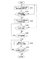
この第2の実施形態のコントローラ21による制御を図12のフローチャートを基にして説明する。なお、この場合も、参考例と同一ステップに同一ステップ符号を付し、重複する説明を省力するものとする。
Control by the
この第2の実施形態の制御は、ステップS101の情報の読み込みからステップS104のウェビング引き出し方向の回転判定までは参考例と同様である。
ステップS104において、NO、つまりウェビング引き出し方向の回転無しと判定された場合には、ステップS301に進む。
ステップS301においては、ヨーレートや加速度(横加速度及び/又は前後加速度)等の現在の車両の状態信号と、路面μを読み込む。なお、路面μは、駆動状態と車輪スリップ率等を基にして演算によって求める。
つづく、ステップS302においては、路面μが所定値(車両が大きくスリップする可能性の高い値)以下であるか否かを判定する。ここで、YESの場合には、ステップS303に進み、NOの場合には、ステップS304に進む。
The control of the second embodiment is the same as that of the reference example from the reading of information in step S101 to the rotation determination in the webbing pull-out direction in step S104.
If NO in step S104, that is, if it is determined that there is no rotation in the webbing pull-out direction, the process proceeds to step S301.
In step S301, the current vehicle state signal such as the yaw rate and acceleration (lateral acceleration and / or longitudinal acceleration) and the road surface μ are read. The road surface μ is obtained by calculation based on the driving state and the wheel slip rate.
Subsequently, in step S302, it is determined whether or not the road surface μ is equal to or less than a predetermined value (a value at which the vehicle is highly likely to slip). Here, in the case of YES, the process proceeds to step S303, and in the case of NO, the process proceeds to step S304.
ステップS303においては、ヨーレートと加速度がほぼゼロの状態が所定時間以上継続しているか否かを判定し、YESの場合には、ステップS106,ステップS107へと進み、NOの場合には、ステップS104に戻る。したがって、路面μが所定値以下でスリップを生じ易い状況では、車両が完全に安定状態にならない限り、ステップS106に進んで強制的にロックが解除されることはない。 In step S303, it is determined whether or not the yaw rate and acceleration are substantially zero for a predetermined time or more. If YES, the process proceeds to step S106 and step S107. If NO, step S104 is performed. Return to. Therefore, in a situation where the road surface μ is less than or equal to a predetermined value and slip is likely to occur, the process will not proceed to step S106 and the lock will not be forcibly released unless the vehicle becomes completely stable.
ステップS304においては、ヨーレートと加速度がともにゼロよりも充分に大きい所定値以下の状態が所定時間以上継続しているか否かを判定し、YESの場合には、ステップS106,ステップS107へと進み、NOの場合には、ステップS104に戻る。ここではステップS303とほぼ同様の制御となるが、ヨーレートと加速度の閾値が高い分、車両状態がある程度安定したところで、ステップS106,ステップS107へと進むことになる。
なお、ステップS106,ステップS107へと進んだ場合には、参考例と同様に駆動モータ10によって緊急ロック機構22の強制解除を行う。
In step S304, it is determined whether or not a state where both the yaw rate and acceleration are sufficiently less than a predetermined value that is sufficiently larger than zero continues for a predetermined time or more. If YES, the process proceeds to step S106 and step S107. If NO, the process returns to step S104. Here, the control is almost the same as in step S303, but the process proceeds to step S106 and step S107 when the vehicle state is stabilized to some extent because the threshold values of the yaw rate and acceleration are high.
When the process proceeds to step S106 and step S107, the
この第2の実施形態の場合も、基本的には、参考例と同様に、拘束の不要な状況下では駆動モータ10によって緊急ロック機構22のロックを強制的に解除するため、拘束の不要な状況下でのウェビング5による乗員拘束を無くし、快適性、操作性を向上させることができる。
Also in the case of the second embodiment, basically, as in the case of the reference example , the lock of the
そして、この第2の実施形態では、ロック継続判定中の路面状況に応じてロック解除のためのヨーレートと加速度の判定閾値を変更するため、常に、路面状況に応じて適切にロック解除を実行することができる。 And in this 2nd Embodiment, in order to change the determination threshold value of the yaw rate and acceleration for unlocking according to the road surface condition during lock continuation determination, always unlock appropriately appropriately according to the road surface condition. be able to.
なお、この発明は上記の実施形態に限定されるものではなく、その要旨を逸脱しない範囲で種々の設計変更が可能である。 In addition, this invention is not limited to said embodiment, A various design change is possible in the range which does not deviate from the summary.
1…シートベルト装置
10…駆動モータ
11…回転センサ
12…ベルトリール
15…車速センサ(車両状態検出手段)
16…前後加速度センサ(車両状態検出手段)
17…横加速度センサ(車両状態検出手段)
18…ヨーレートセンサ(車両状態検出手段)
19…車輪速センサ(車両状態検出手段)
21…コントローラ(制御手段)
22…緊急ロック機構
41…ロック継続判定手段
DESCRIPTION OF SYMBOLS 1 ...
16. Longitudinal acceleration sensor (vehicle state detection means)
17 ... Lateral acceleration sensor (vehicle state detection means)
18 ... Yaw rate sensor (vehicle state detection means)
19: Wheel speed sensor (vehicle state detection means)
21 ... Controller (control means)
22 ...
Claims (2)
このベルトリールを巻取り方向に常時付勢する付勢手段と、
車両挙動が不安定になったときに、前記ベルトリールのウェビング引き出し方向の回転を機械的にロックし、前記ベルトリールのウェビング巻取り方向の所定量以上の回転によってロックが自動的に解除される緊急ロック機構と、
前記ベルトリールに回転駆動力を付与する駆動モータと、
前記駆動モータを制御する制御手段と、
を備えた車両のシートベルト装置において、
前記ベルトリールの回転位置を検出する回転位置検出手段と、
車両状態を検出する車両状態検出手段と、
前記駆動モータへの非通電時に、車両状態検出手段によって検出される車両状態と前記回転位置検出手段によって検出されるベルトリールの回転位置の変化に基づいて、前記緊急ロック機構の作動後にロック状態が継続しているか否かを判定するロック継続判定手段と、を設け、
前記制御手段は、前記ロック継続判定手段が所定時間以上ロック状態の継続を判定したときに、前記駆動モータをロック解除方向に回転駆動させるとともに、ロック解除を行うための前記駆動モータの駆動開始時間を、前記ロック継続判定手段による判定中の車速に応じ、車速が速くなるに従って遅くなるように調整することを特徴とする車両のシートベルト装置。 A belt reel wound with webbing,
A biasing means for constantly biasing the belt reel in the winding direction;
When the vehicle behavior becomes unstable, the rotation of the belt reel in the webbing pull-out direction is mechanically locked, and the lock is automatically released by the rotation of the belt reel in the webbing winding direction by a predetermined amount or more. Emergency locking mechanism;
A drive motor for applying a rotational driving force to the belt reel;
Control means for controlling the drive motor;
In a vehicle seat belt device comprising:
Rotational position detecting means for detecting the rotational position of the belt reel;
Vehicle state detection means for detecting the vehicle state;
Based on the vehicle state detected by the vehicle state detecting means and the change in the rotational position of the belt reel detected by the rotational position detecting means when the drive motor is de-energized, the locked state is activated after the emergency lock mechanism is activated. A lock continuation determining means for determining whether or not it continues,
The control means rotates the drive motor in the unlocking direction when the lock continuation determining means determines that the locked state is continued for a predetermined time or more, and the drive start time of the drive motor for releasing the lock. According to the vehicle speed being determined by the lock continuation determining means so as to become slower as the vehicle speed increases .
このベルトリールを巻取り方向に常時付勢する付勢手段と、A biasing means for constantly biasing the belt reel in the winding direction;
車両挙動が不安定になったときに、前記ベルトリールのウェビング引き出し方向の回転を機械的にロックし、前記ベルトリールのウェビング巻取り方向の所定量以上の回転によってロックが自動的に解除される緊急ロック機構と、When the vehicle behavior becomes unstable, the rotation of the belt reel in the webbing pull-out direction is mechanically locked, and the lock is automatically released by the rotation of the belt reel in the webbing winding direction by a predetermined amount or more. Emergency locking mechanism;
前記ベルトリールに回転駆動力を付与する駆動モータと、A driving motor for applying a rotational driving force to the belt reel;
前記駆動モータを制御する制御手段と、Control means for controlling the drive motor;
を備えた車両のシートベルト装置において、In a vehicle seat belt apparatus comprising:
前記ベルトリールの回転位置を検出する回転位置検出手段と、Rotational position detecting means for detecting the rotational position of the belt reel;
車両状態を検出する車両状態検出手段と、Vehicle state detection means for detecting the vehicle state;
前記駆動モータへの非通電時に、車両状態検出手段によって検出される車両状態と前記回転位置検出手段によって検出されるベルトリールの回転位置の変化に基づいて、前記緊急ロック機構の作動後にロック状態が継続しているか否かを判定するロック継続判定手段と、を設け、Based on the vehicle state detected by the vehicle state detecting means and the change in the rotational position of the belt reel detected by the rotational position detecting means when the drive motor is de-energized, the locked state is activated after the emergency lock mechanism is activated. A lock continuation determining means for determining whether or not it continues,
前記制御手段は、前記ロック継続判定手段が所定時間以上ロック状態の継続を判定したときに、前記駆動モータをロック解除方向に回転駆動させるとともに、ロック解除を行うための前記駆動モータの駆動開始時間を、前記ロック継続判定手段による判定中の路面状況に応じて変更することを特徴とする車両のシートベルト装置。The control means rotates the drive motor in the unlocking direction when the lock continuation determining means determines that the locked state is continued for a predetermined time or more, and the drive start time of the drive motor for releasing the lock. According to the road surface condition being determined by the lock continuation determining means.
Priority Applications (4)
| Application Number | Priority Date | Filing Date | Title |
|---|---|---|---|
| JP2008322381A JP4510913B2 (en) | 2008-12-18 | 2008-12-18 | Vehicle seat belt device |
| US12/577,779 US8141806B2 (en) | 2008-12-18 | 2009-10-13 | Seatbelt apparatus for vehicle |
| DE602009001178T DE602009001178D1 (en) | 2008-12-18 | 2009-10-13 | Seat belt device for vehicle |
| EP09172879A EP2199160B1 (en) | 2008-12-18 | 2009-10-13 | Seatbelt apparatus for vehicle |
Applications Claiming Priority (1)
| Application Number | Priority Date | Filing Date | Title |
|---|---|---|---|
| JP2008322381A JP4510913B2 (en) | 2008-12-18 | 2008-12-18 | Vehicle seat belt device |
Publications (2)
| Publication Number | Publication Date |
|---|---|
| JP2010143381A JP2010143381A (en) | 2010-07-01 |
| JP4510913B2 true JP4510913B2 (en) | 2010-07-28 |
Family
ID=41396238
Family Applications (1)
| Application Number | Title | Priority Date | Filing Date |
|---|---|---|---|
| JP2008322381A Active JP4510913B2 (en) | 2008-12-18 | 2008-12-18 | Vehicle seat belt device |
Country Status (4)
| Country | Link |
|---|---|
| US (1) | US8141806B2 (en) |
| EP (1) | EP2199160B1 (en) |
| JP (1) | JP4510913B2 (en) |
| DE (1) | DE602009001178D1 (en) |
Families Citing this family (5)
| Publication number | Priority date | Publication date | Assignee | Title |
|---|---|---|---|---|
| EP2543559B1 (en) * | 2010-03-04 | 2014-09-03 | Honda Motor Co., Ltd. | Vehicle seat belt device |
| CN102858602B (en) | 2010-04-23 | 2015-11-25 | 本田技研工业株式会社 | Seat safety belt apparatus |
| JP5556747B2 (en) * | 2011-06-20 | 2014-07-23 | 株式会社デンソー | Seat belt control device |
| US9150193B2 (en) * | 2012-06-14 | 2015-10-06 | Autoliv Asp, Inc. | Mode detection switch assembly for self-locking dual-mode seat belt retractor |
| CN111284373B (en) * | 2018-12-07 | 2021-07-20 | 宝沃汽车(中国)有限公司 | Seat control method and device, vehicle and computer readable storage medium |
Citations (2)
| Publication number | Priority date | Publication date | Assignee | Title |
|---|---|---|---|---|
| JP2004262258A (en) * | 2003-01-23 | 2004-09-24 | Autoliv Japan Ltd | Occupant restraint safety device for vehicle |
| JP2005028970A (en) * | 2003-07-10 | 2005-02-03 | Toyota Motor Corp | Seat belt device for vehicle |
Family Cites Families (7)
| Publication number | Priority date | Publication date | Assignee | Title |
|---|---|---|---|---|
| DE10061040A1 (en) * | 2000-12-08 | 2002-06-13 | Daimler Chrysler Ag | Process for controlling a reversible belt tensioner |
| US6685124B2 (en) * | 2001-11-30 | 2004-02-03 | Trw Vehicle Safety Systems Inc. | Seat belt pretensioner with brake |
| DE10332024A1 (en) * | 2003-07-15 | 2005-02-17 | Daimlerchrysler Ag | Method for controlling a reversible belt tensioner in a motor vehicle |
| WO2006043590A1 (en) * | 2004-10-19 | 2006-04-27 | Autoliv Development Ab | Retractor for seat belt, method of controlling the retractor, and seat belt device |
| JP4726727B2 (en) * | 2006-07-18 | 2011-07-20 | 本田技研工業株式会社 | Vehicle seat belt device |
| DE102006044456A1 (en) * | 2006-09-21 | 2008-04-17 | Trw Automotive Gmbh | Safety belt retractor's electric motor controlling method for vehicle, involves examining whether blocking system reaches into blocking condition, in which belt coil is blocked in winding up direction when safety belt is tightened |
| JP2008105552A (en) | 2006-10-25 | 2008-05-08 | Mazda Motor Corp | Vehicle seat belt control device |
-
2008
- 2008-12-18 JP JP2008322381A patent/JP4510913B2/en active Active
-
2009
- 2009-10-13 EP EP09172879A patent/EP2199160B1/en active Active
- 2009-10-13 US US12/577,779 patent/US8141806B2/en active Active
- 2009-10-13 DE DE602009001178T patent/DE602009001178D1/en active Active
Patent Citations (2)
| Publication number | Priority date | Publication date | Assignee | Title |
|---|---|---|---|---|
| JP2004262258A (en) * | 2003-01-23 | 2004-09-24 | Autoliv Japan Ltd | Occupant restraint safety device for vehicle |
| JP2005028970A (en) * | 2003-07-10 | 2005-02-03 | Toyota Motor Corp | Seat belt device for vehicle |
Also Published As
| Publication number | Publication date |
|---|---|
| JP2010143381A (en) | 2010-07-01 |
| US8141806B2 (en) | 2012-03-27 |
| DE602009001178D1 (en) | 2011-06-09 |
| US20100156083A1 (en) | 2010-06-24 |
| EP2199160A1 (en) | 2010-06-23 |
| EP2199160B1 (en) | 2011-04-27 |
Similar Documents
| Publication | Publication Date | Title |
|---|---|---|
| JP4510913B2 (en) | Vehicle seat belt device | |
| JP2011025764A (en) | Seat belt device for vehicle | |
| JP4603066B2 (en) | Vehicle seat belt device and control method thereof | |
| JP2005028970A (en) | Seat belt device for vehicle | |
| US8818643B2 (en) | Seatbelt device | |
| JP7135723B2 (en) | Vehicle seat belt controller | |
| JP5244484B2 (en) | Vehicle seat belt device and control method thereof | |
| JP4758835B2 (en) | Vehicle seat belt device | |
| JP5210745B2 (en) | Vehicle seat belt device and control method thereof | |
| JP2010089562A (en) | Seat belt device | |
| JP4597755B2 (en) | Seat belt device | |
| JP5438608B2 (en) | Seat belt device | |
| JP4082223B2 (en) | Vehicle seat belt device | |
| JP5210780B2 (en) | Vehicle seat belt device | |
| JP5069761B2 (en) | Seat belt device | |
| JP5268807B2 (en) | Vehicle seat belt device | |
| JP2008110691A (en) | Vehicular seat belt control device | |
| JP5478670B2 (en) | Seat belt device | |
| JP5557697B2 (en) | Seat belt device | |
| JP5538051B2 (en) | Vehicle seat belt device | |
| JP4778036B2 (en) | Vehicle seat belt device | |
| JP4658867B2 (en) | Vehicle seat belt device | |
| JP4843434B2 (en) | Vehicle seat belt device | |
| JP2008114771A (en) | Vehicle seat belt control device | |
| JP2008105552A (en) | Vehicle seat belt control device |
Legal Events
| Date | Code | Title | Description |
|---|---|---|---|
| TRDD | Decision of grant or rejection written | ||
| A01 | Written decision to grant a patent or to grant a registration (utility model) |
Free format text: JAPANESE INTERMEDIATE CODE: A01 Effective date: 20100406 |
|
| A01 | Written decision to grant a patent or to grant a registration (utility model) |
Free format text: JAPANESE INTERMEDIATE CODE: A01 |
|
| A61 | First payment of annual fees (during grant procedure) |
Free format text: JAPANESE INTERMEDIATE CODE: A61 Effective date: 20100430 |
|
| FPAY | Renewal fee payment (event date is renewal date of database) |
Free format text: PAYMENT UNTIL: 20130514 Year of fee payment: 3 |
|
| R150 | Certificate of patent or registration of utility model |
Ref document number: 4510913 Country of ref document: JP Free format text: JAPANESE INTERMEDIATE CODE: R150 Free format text: JAPANESE INTERMEDIATE CODE: R150 |
|
| FPAY | Renewal fee payment (event date is renewal date of database) |
Free format text: PAYMENT UNTIL: 20130514 Year of fee payment: 3 |
|
| FPAY | Renewal fee payment (event date is renewal date of database) |
Free format text: PAYMENT UNTIL: 20140514 Year of fee payment: 4 |