JP4510747B2 - Sheet-like material transport device - Google Patents
Sheet-like material transport device Download PDFInfo
- Publication number
- JP4510747B2 JP4510747B2 JP2005320888A JP2005320888A JP4510747B2 JP 4510747 B2 JP4510747 B2 JP 4510747B2 JP 2005320888 A JP2005320888 A JP 2005320888A JP 2005320888 A JP2005320888 A JP 2005320888A JP 4510747 B2 JP4510747 B2 JP 4510747B2
- Authority
- JP
- Japan
- Prior art keywords
- sheet
- paper
- conveying
- suction
- holding means
- Prior art date
- Legal status (The legal status is an assumption and is not a legal conclusion. Google has not performed a legal analysis and makes no representation as to the accuracy of the status listed.)
- Expired - Fee Related
Links
Images


Description
本発明は、シート状物搬送方向の上流側から1枚ずつ給紙されてきたシート状物を印刷胴等の爪にくわえ替えするためのシート状物搬送装置に関するものである。 The present invention relates to a sheet-like material conveying apparatus for replacing sheet-like materials fed one by one from the upstream side in the sheet-like material conveying direction with a nail such as a printing cylinder.
この種のシート状物搬送装置として最も典型的なものとして枚葉輪転印刷機におけるスイング装置がある。このスイング装置としては、給紙装置から1枚ずつ紙が給紙される差板と印刷ユニットの渡し胴との間に設けられ、左右のフレームに軸架されたスイング軸に割締め固定されたスイングアームと、このスイングアームの揺動端部に設けられ爪と爪台とからなり開閉駆動装置によって開閉する複数組のくわえ爪装置とを備えたものがある。このスイング装置は、カム機構によってスイング軸を所定角度ずつ正逆方向に回動させることにより、スイングアームが所定角度ずつ正逆方向に揺動し、くわえ爪装置が差板上へ搬送されてきた紙をくわえる受取位置と、この受取位置から渡し胴に紙を受け渡す受渡位置との間を揺動する(例えば、特許文献1参照)。
上述した従来のシート状物搬送装置においては、紙のくわえを爪と爪台とからなるくわえ爪装置によって行うため、爪を爪台から開閉させるための爪開閉機構が必要になり、その分重量が増加する。このため、スイングアームの慣性モーメントが大きくなることにより、受取位置と受渡位置とにおける位置精度が低下して、爪どうしのくわえ替え不良が発生するという問題があった。また、受渡位置から受取位置に戻る際に爪が開くため、開いた爪が紙の搬送軌跡上に進出し、渡し胴の爪にくわえ替えられて搬送される紙の尻側が開いた爪で擦れることによって、紙に傷や擦れが発生するという問題もあった。 In the conventional sheet-like material conveying device described above, since the gripping of the paper is performed by the gripping claw device composed of the claw and the claw base, a claw opening / closing mechanism for opening and closing the claw from the claw base is necessary, and the weight correspondingly Will increase. For this reason, when the moment of inertia of the swing arm is increased, the positional accuracy at the receiving position and the delivery position is lowered, and there is a problem in that a claw is not properly replaced. In addition, since the nail opens when returning from the delivery position to the receipt position, the opened nail advances on the paper conveyance path, and the bottom side of the paper to be conveyed is rubbed with the open nail in place of the nail of the transfer cylinder. As a result, there was a problem that the paper was scratched or rubbed.
本発明は上記した従来の問題に鑑みなされたものであり、その目的とするところは、くわえ替え不良を防止し、シート状物に擦れや傷を付けないようにしたシート状物搬送装置を提供するところにある。 The present invention has been made in view of the above-described conventional problems, and an object of the present invention is to provide a sheet-like material conveying device that prevents a defective holding and does not rub or scratch the sheet-like material. There is a place to do.
この目的を達成するために、請求項1に係る発明は、シート状物を搬送する第1のシート搬送手段と、この第1のシート搬送手段のシート搬送方向下流側に設けられ、この第1のシート搬送手段からシート状物を受け取る第1のシート保持手段が設けられた第2のシート搬送手段と、この第2のシート搬送手段のシート搬送方向下流側に設けられ、この第2のシート搬送手段からシート状物を受け取る第2のシート保持手段が設けられた第3のシート搬送手段とを備え、前記第1のシート保持手段は、前記第1のシート搬送手段からシート状物を受け取る受取位置と、この受取位置で受け取ったシート状物を前記第3のシート搬送手段へ受け渡す受渡位置との間で揺動自在に支持されたシート状物搬送装置において、前記第1のシート保持手段に、前記受取位置から前記受渡位置への移動時に吸気源に接続されてシート状物を吸着する孔部を備え、前記第1のシート保持手段は、シート状物の幅方向に複数設けられ、この複数の第1のシート保持手段は、シート状物の幅方向に移動不能な固定シート保持手段と、シート状物の幅方向の両端側に設けられ、シート状物を幅方向に張る方向に移動する移動シート保持手段とからなるものである。 To this end, the invention according to claim 1 includes a first sheet conveying means for conveying the sheet, provided in the sheet conveyance direction downstream side of the first sheet conveyance means, this A second sheet conveying means provided with a first sheet holding means for receiving a sheet-like material from the first sheet conveying means; and a second sheet conveying means provided downstream of the second sheet conveying means in the sheet conveying direction. And a third sheet conveying means provided with a second sheet holding means for receiving a sheet-like material from the sheet conveying means, wherein the first sheet holding means is a sheet-like material from the first sheet conveying means. a receiving position to receive, in the sheet transporting device swingably supported between the receiving position in the sheet-like material received passes to the third sheet conveying means delivery position, said first Sheet holding hands In, which is connected from the receiving position to the suction air source upon movement to the delivery position includes a hole for adsorbing a sheet product, the first sheet holding means is a plurality in the width direction of the sheet, The plurality of first sheet holding means are provided on the both ends of the sheet-like material in the width direction, and fixed in the direction of stretching the sheet-like material in the width direction. The moving sheet holding means moves .
請求項2に係る発明は、請求項1に係る発明において、前記第1のシート保持手段は、前記受渡位置から前記受取位置への移動時にエアを吐出する吐出源に接続するものである。
The invention according to
請求項3に係る発明は、請求項1に係る発明において、前記移動シート保持手段は、シート状物を吸着することにより前記第1のシート保持手段内に発生する負圧によって移動するように構成したものである。According to a third aspect of the present invention, in the first aspect of the invention, the moving sheet holding means is configured to move by a negative pressure generated in the first sheet holding means by adsorbing a sheet-like object. It is a thing.
請求項4に係る発明は、請求項1に係る発明において、前記第1のシート搬送手段のシート搬送方向下流側に設けられ、搬送されるシート状物を前記第1のシート保持手段方向に吸引する吸引手段を備えたものである。According to a fourth aspect of the present invention, in the first aspect of the invention, the sheet-like object that is provided downstream of the first sheet conveying unit in the sheet conveying direction is sucked in the direction of the first sheet holding unit. It is provided with a suction means.
請求項5に係る発明は、請求項4に係る発明において、前記第1のシート搬送手段に横針手段を設け、前記第1のシート搬送手段によって搬送されるシート状物は、前記横針手段によってシート状物の幅方向の見当が揃えられた後、前記吸引手段によってシート状物の先端側が吸引される。The invention according to
請求項1に係る発明によれば、爪および爪を開閉させる開閉機構を必要としないため、従来の装置と比較して軽量化を図ることができる。したがって、第1のシート搬送手段からシート状物を受け取る受取位置と、この受取位置で受け取ったシート状物を第3の搬送手段へ受け渡す受渡位置との間を揺動する第2のシート搬送手段の慣性モーメントが小さくなる。このため、受取位置と受渡位置とにおける位置精度が向上するからシート状物のくわえ替え不良の発生を防止することができる。また、第2のシート搬送手段を軽量化することにより、高速における揺動動作も安定する。また、爪を必要としないため、第2のシート搬送手段が受渡位置から受取位置に移動する際に、第3のシート搬送手段によって搬送される紙が爪によって擦れるようなことがないから紙に擦れや傷が付くようなことがない。また、従来のように爪どうしのくわえ替えがないから、シート状物の両端部に無保持部分が発生しないように、シート状物を吸着する孔部の表面積を拡げることが可能なため、角折れの発生を阻止することができる。また、第1のシート搬送手段の当てに当接させたシート状物に波打ちが発生していたとしても、シート状物が幅方向に引っ張られて緊張し平坦状に矯正されるため、当ておよび横針装置による見当精度を向上させることができる。 According to the first aspect of the present invention, since the claw and the opening / closing mechanism for opening and closing the claw are not required, the weight can be reduced as compared with the conventional device. Therefore, the second sheet conveyance swinging between the receiving position for receiving the sheet-like material from the first sheet conveying means and the delivery position for delivering the sheet-like material received at the receiving position to the third conveying means. The moment of inertia of the means is reduced. For this reason, since the positional accuracy at the receiving position and the delivery position is improved, it is possible to prevent occurrence of a defective holding of the sheet-like material. Further, by reducing the weight of the second sheet conveying means, the swinging operation at high speed can be stabilized. Further, since the nail is not required, the paper conveyed by the third sheet conveying unit is not rubbed by the nail when the second sheet conveying unit moves from the delivery position to the receiving position. There is no rubbing or scratching. In addition, since there is no replacement of the claws as in the conventional case, the surface area of the hole portion that adsorbs the sheet-like material can be increased so that no non-holding portions are generated at both ends of the sheet-like material. Breakage can be prevented. Further, even if the sheet-like material abutted against the contact of the first sheet conveying means is wavy, the sheet-like material is pulled in the width direction and is tensioned and corrected to a flat shape. Registration accuracy by the horizontal needle device can be improved.
請求項2に係る発明によれば、第3のシート搬送手段の第2の保持手段にくわえ替えられて搬送されるシート状物が、第1のシート保持手段から吐出されるエアによって第1のシート保持手段から確実に離間するため、シート状物に第1のシート保持手段が接触しないからシート状物に擦れや傷が付いたりするようなことがない。 According to the second aspect of the present invention, the sheet-like material conveyed by being transferred to the second holding unit of the third sheet conveying unit is transferred to the first sheet by the air discharged from the first sheet holding unit. Since the first sheet holding means does not come into contact with the sheet-like material because it is reliably separated from the sheet holding means, the sheet-like material is not rubbed or scratched.
請求項3に係る発明によれば、シート状物を吸着するエアによって移動シート保持面の移動を行うようにしたため、移動シート保持面の移動のための専用のエアの供給手段を設ける必要がないから構造が簡素化される。According to the invention of
請求項4に係る発明によれば、搬送されるシート状物の先端部が反っている場合、第1のシート保持手段に保持される直前に吸引手段によって反っている部分が第1のシート保持手段側に矯正されるため、第1のシート保持手段によってシート状物を確実に保持することができる。According to the fourth aspect of the present invention, when the leading end of the conveyed sheet-like material is warped, the portion warped by the suction means immediately before being held by the first sheet holding means is the first sheet holding. Since the correction is made on the means side, the sheet-like object can be reliably held by the first sheet holding means.
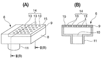
以下、本発明の実施の形態を図に基づいて説明する。図1は本発明に係るシート状物搬送装置の側面図、図2(A)は同じく吸着ヘッドを拡大して示す斜視図、同図(B)は同図(A)におけるII(B)-II(B) 線断面図、図3は従来の装置と比較したモデル図で、同図(A)は本発明における吸着ヘッドによって紙を搬送する状態を示す平面図、同図(B)は従来における爪によって紙を搬送する状態を示す平面図である。 Hereinafter, embodiments of the present invention will be described with reference to the drawings. FIG. 1 is a side view of a sheet-like material conveyance device according to the present invention, FIG. 2A is an enlarged perspective view of the same suction head, and FIG. 1B is II (B) − in FIG. II (B) is a cross-sectional view taken along the line, FIG. 3 is a model diagram compared with a conventional apparatus, FIG. 3 (A) is a plan view showing a state in which paper is conveyed by the suction head of the present invention, and FIG. It is a top view which shows the state which conveys paper with the nail | claw in.
図1に符号1で示すものは、図示を省略した給紙装置からシート状物としての紙が1枚ずつ給紙されるフィーダボードであって、このフィーダボード1上には、紙を搬送する第1の搬送手段としての搬送テープ1aが設けられており、フィーダボード1の前方にはこれと同勾配で傾斜する差板2が連結板3によって連結されている。差板2の前端には、図示を省略しているが、紙の先端が当接する紙当て位置と退出位置との間を移動する当てが設けられている。
A reference numeral 1 in FIG. 1 is a feeder board on which sheets of paper are fed one by one from a paper feeding device (not shown), and the paper is conveyed onto the feeder board 1. A
4は両端部が左右のフレームに軸支されたスイング軸であって、このスイング軸4にはスイングアーム5の基端部が割締め固定されている。このスイングアーム5の揺動端部には、第1のシート保持手段としての吸着ヘッド6がスイング軸4の軸線方向に複数個並設されている。これらスイング軸4とスイングアーム5および吸着ヘッド6とによって、第2のシート搬送手段としてのスイング装置7が構成されている。
吸着ヘッド6は、図2に示すように、上方が開口したケース8と、このケース8の開口を覆うように取り付けられたシート保持板9とによって形成されている。ケース8の底部にはエア吸入口10が設けられ、このエア吸入口10に連通する円筒状の接続体11が突設されている。この接続体11にはホース12の一端が嵌合固定されており、ホース12の他端側はロータリバルブを介して吸気源(いずれも図示せず)に接続されている。
As shown in FIG. 2, the
シート保持板9には、多数の吸引孔13からなる孔部14が設けられており、吸気源とホース12との間をロータリバルブによって連通させることによって、シート保持板9の外側のエアが吸引孔13からケース8内に吸引される。このため、シート保持板9の上方に紙が搬送されてくると、紙はシート保持板9の表面に吸着される。したがって、このシート保持板9の表面が固定シート保持面15を形成していることになる。
The sheet holding plate 9 is provided with a
図1において、16は印刷ユニットに軸支された第3のシート搬送手段としての渡し胴であって、この渡し胴16の外周部に設けられた切欠き16a内には、爪17と爪台18とを備え図示しない開閉駆動装置で開閉する複数組の第2のシート保持手段としてのくわえ爪装置(以下、単に爪という)19が渡し胴16の軸線方向に並設されている。
In FIG. 1,
このような構成において、スイング軸4を図示しないカム機構によって所定角度ずつ正逆方向に回動させることにより、スイングアーム5が矢印A−B方向に所定角度の範囲内で揺動する。すなわち、このスイングアーム5の揺動によって、吸着ヘッド6は差板2から紙を受け取る実線で示した受取位置から、この受取位置で受け取った紙を渡し胴16の爪19へ受け渡す一点鎖線で示した受渡位置へ回動し、さらにこの受渡位置から二点鎖線で示す停止位置まで回動して停止するように停止位置と受取位置との間を揺動する。このように揺動する吸着ヘッド6は、ロータリバルブを介して受取位置に位置付けられると吸気源から吸引エアが供給され、受渡位置に位置付けられると吸引エアの供給が停止する。
In such a configuration, by swinging the
次に、このように構成されたシート状物搬送装置において紙を搬送する動作を説明する。予め、スイング装置7のスイングアーム5が矢印B方向に揺動して、吸着ヘッド6が受取位置に位置付けられている。この状態で、図示を省略した給紙装置からフィーダボード1上に1枚ずつ給紙された紙は、前方へ向かって低くなるように傾斜しているフィーダボード1上を、複数条の搬送テープ1aとコロ(図示せず)とで挟持されて搬送される。フィーダボード1上を搬送された紙は、連結板3を介して差板2上を搬送され先端が当て(図示せず)に当接する。
Next, an operation for conveying paper in the sheet-like material conveyance device configured as described above will be described. In advance, the
予め受取位置に位置付けられている吸着ヘッド6には吸引エアが供給されているので、当てに当接した紙は吸着ヘッド6の固定シート保持面15に吸着される。吸着ヘッド6によって紙が吸着されると、スイングアーム5が矢印A方向に揺動し、受渡位置において紙が渡し胴16の爪19にくわえられると同時に、吸着ヘッド6への吸引エアの供給が停止するので、紙は吸着ヘッド6から渡し胴16の爪19にくわえ替えられる。
Since suction air is supplied to the
このように、従来のスイング装置7の紙保持手段を爪と爪台とによるくわえ爪装置から、吸着ヘッド6に替えたことにより、爪および爪を開閉させる開閉機構を必要としないため、軽量化を図ることができるからスイングアーム5の慣性モーメントが小さくなる。このため、差板2から紙を受け取る受取位置と、この受取位置で受け取った紙を渡し胴16の爪19へ受け渡す受渡位置における位置精度が向上するから紙のくわえ替え不良の発生を防止することができる。また、スイング装置7を軽量化することにより、高速における揺動動作も安定する。また、爪を必要としないため、吸着ヘッド6が受渡位置から受取位置に移動する際に、渡し胴16によって搬送される紙の尻側が爪によって擦れるようなことがないから紙に擦れや傷が付くようなことがない。
As described above, the paper holding means of the
また、従来のようにスイング装置7と渡し胴16との間で爪どうしのくわえ替えが必要な場合は、図3(B)に示すようにスイング装置7の爪21,21間に間隔を設ける必要がある。したがって、爪21の幅W1を拡げるには限界があり、紙20のサイズによっては紙20の角部が爪21,21間に位置することがある。このため、紙20の角部が爪21に保持されない無保持状態となるから、この部分が折れ曲がるいわゆる角折れが発生しやすかった。これに対して、本発明によれば、爪どうしのくわえ替えがないから、同図(A)に示すように紙20の角部が無保持状態とならないように、固定シート保持面15の幅W2を拡げることが容易であるため、角折れの発生を阻止することができる。
When it is necessary to replace the claws between the
図4は本発明の第2の実施の形態を示すシート状物搬送装置の側面図である。この第2の実施の形態では、吸着ヘッド6にロータリバルブを介して吸気源とエア供給源(いずれも図示せず)とが接続されている。そして、吸着ヘッド6が受取位置から受渡位置へ移動するときは、上述した第1の実施の形態と同様にロータリバルブを介して吸気源から吸引エアが吸着ヘッド6に供給される。一方、吸着ヘッド6が停止位置から受取位置に移動するときは、ロータリバルブを介してエア供給源から吐出エアが吸着ヘッド6に供給されるように構成されている。
FIG. 4 is a side view of a sheet-like material conveying apparatus showing a second embodiment of the present invention. In the second embodiment, the
このように構成されていることにより、吸着ヘッド6が停止位置から受取位置に移動する際に、吸着ヘッド6からエアが吐出されるため、このエアによって渡し胴16の爪19にくわえられて搬送される紙20の尻側が上方に吹き上げられる。このため、紙20の尻側が吸着ヘッド6から離間するから、紙20が吸着ヘッド6によって擦れるようなことがないから紙に擦れや傷を付けるようなことを確実に阻止することができる。
With this configuration, when the
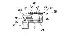
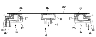
図5ないし図7は本発明の第3の実施の形態を示し、図5は要部の断面図、図6は紙が波を打つ状態を示す斜視図、図7は波を打った紙を平坦状に矯正する状態を説明するための正面から視たモデル図である。 5 to 7 show a third embodiment of the present invention, FIG. 5 is a cross-sectional view of the main part, FIG. 6 is a perspective view showing a state in which the paper undulates, and FIG. It is the model figure seen from the front for demonstrating the state corrected to flatness.
この第3の実施の形態における吸着ヘッド25は、図5に示すように、上方の一部が開口したケース26と、このケース26の開口を覆うようにこのケース27に図中左右方向に摺動自在に支持され上方が開口した移動体27と、この移動体27の開口を覆うように移動体27に取り付けられたシート保持板28とによって形成されている。ケース26の底部にはエア吸入口29が設けられ、このエア吸入口29に連通する円筒状の接続体30が突設されている。この接続体30にはホース12の一端が嵌合固定されており、ホース12の他端側はロータリバルブを介して吸気源(いずれも図示せず)に接続されている。
As shown in FIG. 5, the
移動体27は有底角筒状に形成され、一方の側面の下部には角筒状の摺動部31が突設されており、上端にはフランジ32が設けられ、全体が中空状に形成されている。この移動体27は、摺動部31がケース26に嵌合され、摺動部31とフランジ32とでケース26の上板26aを挟持することにより、ケース26に図中左右方向に摺動自在に支持されている。この状態で、ケース26のエア吸入口29と移動体27の上部開口とが連通されている。33はケース26と移動体27との間に弾装された圧縮コイルばねであって、移動体27を図中右方向に付勢していることになる。
The
シート保持板28には、多数の吸引孔34からなる孔部35が設けられており、吸気源とエア吸入口29との間をロータリバルブによって連通させることによって、シート保持板28の外側のエアが吸引孔34から移動体27内に吸引される。このため、シート保持板28の上方に紙が搬送されてくると、紙はシート保持板28の表面に吸着される。シート保持板28の表面に紙が吸着されると、ケース26内が気密状態になるため、さらにケース26内に吸気源から吸引エアを供給することにより、移動体27が圧縮コイルばね33の弾発力に抗して図中左方に移動する。したがって、このシート保持板28の表面が移動シート保持面36を形成している。
The
一対の吸着ヘッド25,25を、図7に示すように紙20の幅方向の両端側に、それぞれの移動体27,27が紙20の幅方向を互いに反対方向に移動するように、ケース26をスイングアーム5に取り付ける。また、上記した第1の実施の形態で説明した固定シート保持面15を有する吸着ヘッド6を紙20の幅方向の中央部に設ける。このような構成において、図6に示すように波を打った状態で当て37に先端が当接した紙20は、この受取位置において、吸気源から吸引エアが供給されている吸着ヘッド6,25によって吸着される。
As shown in FIG. 7, the pair of suction heads 25, 25 is moved to both ends in the width direction of the
吸着された後、さらに吸着ヘッド25,25に吸引エアが供給され続けていることにより、各移動シート保持面36,36が紙20の幅方向を互いに反対方向へ移動する。したがって、受取位置でこれら吸着ヘッド6,25に吸着された紙20は、幅方向が引っ張られるため平坦状に緊張するように矯正されるため、当ておよび横針装置による見当精度を向上させることができる。また、移動シート保持面36に紙を吸着させるために吸引エアを供給する吸気源を使って移動シート保持面36の移動も行うようにしたため、吸気源およびロータリバルブを共用することができるから構造を簡素化することができる。
After being sucked, the suction air is continuously supplied to the suction heads 25, 25, whereby the movable sheet holding surfaces 36, 36 move in the width direction of the
なお、この第3の実施の形態においては、紙20の幅方向の両端側に一対の吸着ヘッド25,25を設けるようにしたが、紙20の幅方向の一端側に横針装置が設けられている場合は、必ずしも両端側に設ける必要はなく、他端側にのみ設けるようにしてもよい。
In the third embodiment, the pair of suction heads 25, 25 are provided at both ends in the width direction of the
図8および図9は本発明の第4の実施の形態を示し、図8は要部の側面図、図9は吸引エアの供給状態を示すタイムチャートである。図8において、40は吸引手段としての補助吸いであって、差板2の紙搬送方向下流側であって吸着ヘッド6に対して紙搬送方向上流側に設けられ、紙20を上述した吸着ヘッド6側に吸引するように構成されている。この補助吸い40と符号42で示す横針装置は、いずれも吸着ヘッド6が接続されたロータリバルブを介して、吸着ヘッド6に吸引エアを供給する吸気源(いずれも図示せず)に接続されている。
8 and 9 show a fourth embodiment of the present invention, FIG. 8 is a side view of the main part, and FIG. 9 is a time chart showing a supply state of suction air. In FIG. 8,
次に、図9を用いて、このように構成された第4の実施の形態における紙の搬送動作について説明する。差板2上を搬送された紙20の先端が当てに当接すると、ロータリバルブを介して吸気源から横針装置42に吸引エアが供給されるため、紙20は横針装置42によって吸引され幅方向の見当が揃えられる。この見当が終了すると、ロータリバルブを介して吸気源から補助吸い40に吸引エアが供給されるため、この補助吸い40によって紙20の先端部20aが吸着ヘッド6側に吸引される。次いで、ロータリバルブを介して吸気源から吸着ヘッド6に吸引エアが供給されるため、紙20の先端部20aが吸着ヘッド6の固定シート保持面15に吸着される。
Next, with reference to FIG. 9, a paper transport operation in the fourth embodiment configured as described above will be described. When the leading edge of the
このとき、紙20が厚紙で先端部20aに反りが発生していたとしても、先端部20aが吸着ヘッド6に吸引される直前に、補助吸い40によって先端部20aが吸引ヘッド6側に吸引されているため、先端部20aが確実に固定シート保持面15に吸着される。また、先端部20aの反りを矯正することにより、紙20が当てを乗り越えるようなことがない。固定シート保持面15に紙20の先端部20aが吸着された後、スイング装置7のスイングアーム5が回動し、吸着ヘッド6が受渡位置に位置付けられると、吸着ヘッド6への吸引エアの供給が停止するので、紙20は渡し胴16の爪19にくわえ替えられる。
At this time, even if the
図10は第4の実施の形態の変形例を示す要部の側面図である。この変形例では、補助吸いとして、上述した第3の実施の形態において説明した移動シート保持面36を有する吸着ヘッド25を用い、ケース26を差板2に取り付けることにより、紙20を吸着した移動シート保持面36を吸着ヘッド6側に移動可能としたものである。このように構成されていることにより、当てに紙20の先端が当接したときに、当接した衝撃によって紙20が搬送方向と反対側に移動し、紙20の先端と当てとの間に隙間が発生したとしても、紙20が移動シート保持面36に吸着されることにより、移動シート保持面36が紙搬送方向に移動する。このため、紙20の先端が当てに当接して天地方向の見当が揃えられるから、吸着ヘッド6の固定シート保持面15に確実かつ精度よく吸着される。
FIG. 10 is a side view of an essential part showing a modification of the fourth embodiment. In this modification, as the auxiliary suction, the
なお、本実施の形態においては、シート状物として紙の例を説明したが、フィルム等であってもよい。 In the present embodiment, an example of paper as a sheet-like material has been described, but a film or the like may be used.
1…フィーダボード、2…差板(第1のシート搬送手段)、4…スイング軸、5…スイングアーム、6,25…吸着ヘッド(第1のシート保持手段)、7…スイング装置(第2のシート搬送手段)、14,35…孔部、15…固定シート保持面、16…渡し胴(第3のシート搬送手段)、19…くわえ爪装置(第2のシート保持手段)、20…紙(シート状物)、35…移動シート保持面、37…当て、40…補助吸い(吸引手段)、42…横針装置。 DESCRIPTION OF SYMBOLS 1 ... Feeder board, 2 ... Difference board (1st sheet conveyance means), 4 ... Swing axis | shaft, 5 ... Swing arm, 6,25 ... Adsorption head (1st sheet holding means), 7 ... Swing apparatus (2nd Sheet conveying means), 14, 35 ... holes, 15 ... fixed sheet holding surface, 16 ... transfer cylinder (third sheet conveying means), 19 ... gripper device (second sheet holding means), 20 ... paper (Sheet-like material), 35 ... moving sheet holding surface, 37 ... contact, 40 ... auxiliary suction (suction means), 42 ... horizontal needle device.
Claims (5)
この第1のシート搬送手段のシート搬送方向下流側に設けられ、この第1のシート搬送手段からシート状物を受け取る第1のシート保持手段が設けられた第2のシート搬送手段と、
この第2のシート搬送手段のシート搬送方向下流側に設けられ、この第2のシート搬送手段からシート状物を受け取る第2のシート保持手段が設けられた第3のシート搬送手段とを備え、
前記第1のシート保持手段は、前記第1のシート搬送手段からシート状物を受け取る受取位置と、この受取位置で受け取ったシート状物を前記第3のシート搬送手段へ受け渡す受渡位置との間で揺動自在に支持されたシート状物搬送装置において、
前記第1のシート保持手段に、前記受取位置から前記受渡位置への移動時に吸気源に接続されてシート状物を吸着する孔部を備え、
前記第1のシート保持手段は、シート状物の幅方向に複数設けられ、
この複数の第1のシート保持手段は、シート状物の幅方向に移動不能な固定シート保持手段と、シート状物の幅方向の両端側に設けられ、シート状物を幅方向に張る方向に移動する移動シート保持手段とからなることを特徴とするシート状物搬送装置。 First sheet conveying means for conveying a sheet-like material;
Provided in the sheet conveyance direction downstream side of the first sheet conveyance means, and second sheet conveying means for the first sheet holding means for receiving the sheet from the first sheet conveying means is provided,
A third sheet conveying means provided on the downstream side in the sheet conveying direction of the second sheet conveying means, and provided with a second sheet holding means for receiving a sheet-like material from the second sheet conveying means,
The first sheet holding means, said a receiving position for receiving the sheet from the first sheet conveying means, between the receiving position in the received sheet receiving and passes the delivery position to the third sheet conveying means In the sheet-like material conveying device supported so as to be swingable between,
The first sheet holding means is provided with a hole portion that is connected to an intake source and adsorbs a sheet-like object when moving from the receiving position to the delivery position,
A plurality of the first sheet holding means are provided in the width direction of the sheet-like material,
The plurality of first sheet holding means are provided on the both ends of the sheet-like material in the width direction, and fixed in the direction of stretching the sheet-like material in the width direction. A sheet-like object conveying apparatus comprising a moving sheet holding means that moves .
前記第1のシート保持手段は、前記受渡位置から前記受取位置への移動時にエアを吐出する吐出源に接続することを特徴とするシート状物搬送装置。 In the sheet-like article conveyance device according to claim 1,
The sheet conveying apparatus, wherein the first sheet holding unit is connected to a discharge source that discharges air when moving from the delivery position to the reception position.
前記移動シート保持手段は、シート状物を吸着することにより前記第1のシート保持手段内に発生する負圧によって移動することを特徴とするシート状物搬送装置。 The moving sheet holding means moves by a negative pressure generated in the first sheet holding means by adsorbing the sheet-like object.
前記第1のシート搬送手段のシート搬送方向下流側に設けられ、搬送されるシート状物を前記第1のシート保持手段方向に吸引する吸引手段を備えたことを特徴とするシート状物搬送装置。 A sheet-like article conveying apparatus provided with a suction means that is provided downstream of the first sheet conveying means in the sheet conveying direction and sucks the conveyed sheet-like substance in the direction of the first sheet holding means. .
前記第1のシート搬送手段に横針手段を設け、前記第1のシート搬送手段によって搬送されるシート状物は、前記横針手段によってシート状物の幅方向の見当が揃えられた後、前記吸引手段によってシート状物の先端側が吸引されることを特徴とするシート状物搬送装置。 The first sheet conveying means is provided with a horizontal needle means, and the sheet-like material conveyed by the first sheet conveying means is aligned in the width direction of the sheet-like material by the horizontal needle means. A sheet-like material transporting device, wherein the leading end side of the sheet-like material is sucked by a suction means.
Priority Applications (1)
| Application Number | Priority Date | Filing Date | Title |
|---|---|---|---|
| JP2005320888A JP4510747B2 (en) | 2005-11-04 | 2005-11-04 | Sheet-like material transport device |
Applications Claiming Priority (1)
| Application Number | Priority Date | Filing Date | Title |
|---|---|---|---|
| JP2005320888A JP4510747B2 (en) | 2005-11-04 | 2005-11-04 | Sheet-like material transport device |
Publications (3)
| Publication Number | Publication Date |
|---|---|
| JP2007126257A JP2007126257A (en) | 2007-05-24 |
| JP2007126257A5 JP2007126257A5 (en) | 2008-05-01 |
| JP4510747B2 true JP4510747B2 (en) | 2010-07-28 |
Family
ID=38149224
Family Applications (1)
| Application Number | Title | Priority Date | Filing Date |
|---|---|---|---|
| JP2005320888A Expired - Fee Related JP4510747B2 (en) | 2005-11-04 | 2005-11-04 | Sheet-like material transport device |
Country Status (1)
| Country | Link |
|---|---|
| JP (1) | JP4510747B2 (en) |
Families Citing this family (2)
| Publication number | Priority date | Publication date | Assignee | Title |
|---|---|---|---|---|
| JP2008213181A (en) * | 2007-02-28 | 2008-09-18 | Mitsubishi Heavy Ind Ltd | Recording medium conveying device and printing machine |
| CN104797515B (en) * | 2012-10-30 | 2017-12-29 | 鲍勃斯脱梅克斯股份有限公司 | For being maintained at the device of the flaky flat element circulated in processing machine |
Citations (6)
| Publication number | Priority date | Publication date | Assignee | Title |
|---|---|---|---|---|
| JPS5410701Y2 (en) * | 1974-08-20 | 1979-05-16 | ||
| JPS55145950A (en) * | 1979-04-02 | 1980-11-13 | Polygraph Leipzig | Spare gripper |
| JPS59224348A (en) * | 1983-06-02 | 1984-12-17 | Komori Printing Mach Co Ltd | Register for sheet-fed press |
| JP2596351Y2 (en) * | 1993-01-05 | 1999-06-14 | 株式会社小森コーポレーション | Paper guide device for sheet-fed printing press |
| JP2001225986A (en) * | 2000-02-16 | 2001-08-21 | Ricoh Co Ltd | Sheet material holding device |
| JP2003326674A (en) * | 2001-07-23 | 2003-11-19 | Mitsubishi Heavy Ind Ltd | Intermediate cylinder for sheet-feed press, and sheet- feed press |
-
2005
- 2005-11-04 JP JP2005320888A patent/JP4510747B2/en not_active Expired - Fee Related
Patent Citations (6)
| Publication number | Priority date | Publication date | Assignee | Title |
|---|---|---|---|---|
| JPS5410701Y2 (en) * | 1974-08-20 | 1979-05-16 | ||
| JPS55145950A (en) * | 1979-04-02 | 1980-11-13 | Polygraph Leipzig | Spare gripper |
| JPS59224348A (en) * | 1983-06-02 | 1984-12-17 | Komori Printing Mach Co Ltd | Register for sheet-fed press |
| JP2596351Y2 (en) * | 1993-01-05 | 1999-06-14 | 株式会社小森コーポレーション | Paper guide device for sheet-fed printing press |
| JP2001225986A (en) * | 2000-02-16 | 2001-08-21 | Ricoh Co Ltd | Sheet material holding device |
| JP2003326674A (en) * | 2001-07-23 | 2003-11-19 | Mitsubishi Heavy Ind Ltd | Intermediate cylinder for sheet-feed press, and sheet- feed press |
Also Published As
| Publication number | Publication date |
|---|---|
| JP2007126257A (en) | 2007-05-24 |
Similar Documents
| Publication | Publication Date | Title |
|---|---|---|
| US20060170146A1 (en) | Sheet convey apparatus | |
| JP2007001744A (en) | Sheet feeder | |
| WO1999061358A1 (en) | Blank material feeding device having direction correcting function | |
| US8070286B2 (en) | Image recording apparatus | |
| JP4510747B2 (en) | Sheet-like material transport device | |
| JP2013241265A (en) | Sheet reversing device | |
| JP2011148136A (en) | Printing machine for printing on object to be printed and printing method using the same | |
| CN110872020A (en) | Conveying device and image inspection device | |
| US20210138822A1 (en) | Book block feed device | |
| JPH05310335A (en) | Paper feeding device of paper sheet printing machine | |
| JP3552626B2 (en) | Conveying sheet support device and printing device | |
| JPH0596664A (en) | Opening device of folded up sheet into box in box making machine | |
| JP5361423B2 (en) | Image recording device | |
| JP2014151975A (en) | Sheet processing device | |
| JP2008143667A (en) | Swing device for sheet-fed printing press | |
| JP2017075002A (en) | Sheet inverting device | |
| JP2002114390A (en) | Lifting and advancing suction port transmission device for individualizing mechanism of paper sheet processing machine | |
| JP5148461B2 (en) | Image recording device | |
| JP2009035341A (en) | Conveying and processing apparatus | |
| JP4350888B2 (en) | Sheet-like material supply device in sheet-fed rotary printing press | |
| JPH10231040A (en) | Paper sheet separating device | |
| JP2023012031A (en) | Sheet conveyance device | |
| JP2603093Y2 (en) | Paper guide for sheet-fed printing press | |
| JP2020032634A (en) | Image inspection device | |
| JP3224714B2 (en) | Sheet transfer device for sheet-fed printing press |
Legal Events
| Date | Code | Title | Description |
|---|---|---|---|
| A521 | Written amendment |
Free format text: JAPANESE INTERMEDIATE CODE: A523 Effective date: 20080314 |
|
| A621 | Written request for application examination |
Free format text: JAPANESE INTERMEDIATE CODE: A621 Effective date: 20080314 |
|
| A977 | Report on retrieval |
Free format text: JAPANESE INTERMEDIATE CODE: A971007 Effective date: 20090828 |
|
| A131 | Notification of reasons for refusal |
Free format text: JAPANESE INTERMEDIATE CODE: A131 Effective date: 20090915 |
|
| A521 | Written amendment |
Free format text: JAPANESE INTERMEDIATE CODE: A523 Effective date: 20091116 |
|
| TRDD | Decision of grant or rejection written | ||
| A01 | Written decision to grant a patent or to grant a registration (utility model) |
Free format text: JAPANESE INTERMEDIATE CODE: A01 Effective date: 20100406 |
|
| A01 | Written decision to grant a patent or to grant a registration (utility model) |
Free format text: JAPANESE INTERMEDIATE CODE: A01 |
|
| A61 | First payment of annual fees (during grant procedure) |
Free format text: JAPANESE INTERMEDIATE CODE: A61 Effective date: 20100430 |
|
| FPAY | Renewal fee payment (event date is renewal date of database) |
Free format text: PAYMENT UNTIL: 20130514 Year of fee payment: 3 |
|
| R150 | Certificate of patent or registration of utility model |
Free format text: JAPANESE INTERMEDIATE CODE: R150 |
|
| LAPS | Cancellation because of no payment of annual fees |