JP4510686B2 - IMAGING DEVICE AND IMAGING DEVICE CONTROL METHOD - Google Patents
IMAGING DEVICE AND IMAGING DEVICE CONTROL METHOD Download PDFInfo
- Publication number
- JP4510686B2 JP4510686B2 JP2005119023A JP2005119023A JP4510686B2 JP 4510686 B2 JP4510686 B2 JP 4510686B2 JP 2005119023 A JP2005119023 A JP 2005119023A JP 2005119023 A JP2005119023 A JP 2005119023A JP 4510686 B2 JP4510686 B2 JP 4510686B2
- Authority
- JP
- Japan
- Prior art keywords
- still image
- image data
- moving image
- data
- file
- Prior art date
- Legal status (The legal status is an assumption and is not a legal conclusion. Google has not performed a legal analysis and makes no representation as to the accuracy of the status listed.)
- Expired - Fee Related
Links
Images


Description
本発明は撮像装置、撮像装置の制御方法、コンピュータプログラム及び記録媒体に関し、特に、動画撮影中に静止画撮影するために用いて好適な技術に関する。 The present invention relates to an imaging apparatus, a control method for the imaging apparatus, a computer program, and a recording medium, and more particularly to a technique suitable for taking a still image during moving image shooting.
近年、静止画撮影機能に加えて動画撮影機能を備えるデジタルカメラが提案されている。このようなデジタルカメラは、CF(登録商標:Compact Flash)カードなどの外部記録媒体に、動画像データをAVI(Audio Video Interleaving)などのビデオフォーマットで記録する機能を有している。また、デジタルカメラの中には、動画撮影と同時に静止画撮影を行う製品が提案されている。 In recent years, digital cameras having a moving image shooting function in addition to a still image shooting function have been proposed. Such a digital camera has a function of recording moving image data in an external recording medium such as a CF (registered trademark: Compact Flash) card in a video format such as AVI (Audio Video Interleaving). In addition, some digital cameras have been proposed that perform still image shooting simultaneously with moving image shooting.
さらに、デジタルカメラに関する動画撮影中に静止画を取得する技術としては以下のものが提案されている。例えば特許文献1に記載の撮像装置においては、動画撮影中に同時に取得された静止画データを静止画用のバッファに格納しておき、動画撮影終了後に静止画ファイルとして構築する機能を有するものが提案されている。また、特許文献2に記載の撮像装置においては、動画撮影中に同時に静止画撮影がなされた場合に、取得した静止画データをリサイズして動画データの1コマとして適用するとともに、静止画ファイルとして構築する機能を有するものが提案されている。
Further, the following technologies have been proposed as techniques for acquiring still images during moving image shooting related to digital cameras. For example, the imaging device described in
しかしながら、動画データと静止画データを1つのファイルに記録する場合に、従来技術を利用すると以下の課題があった。例えば、特許文献1に記載の撮像装置の場合は、デジタルカメラの有する静止画バッファサイズを使い切ってしまうと、以降に静止画撮影することが不可能になってしまう問題点があった。また、特許文献2に記載の撮像装置の場合は、動画撮影中に静止画撮影の処理が集中して行われると、静止画データのファイルを書き込むための処理が連続的に発生するため、動画データを書き込むためのバンド幅を十分に得ることができなくなり、その結果としてコマ落ちが生じたり、動画撮影が中断したりしてしまう可能性があった。
However, when the moving image data and the still image data are recorded in one file, there are the following problems when the conventional technique is used. For example, in the case of the imaging device described in
本発明は前述の問題点にかんがみ、動画撮影中に同時に取得された静止画データをファイルに効率よく書き込むことができるようにすることを目的としている。 In view of the above-described problems, an object of the present invention is to enable efficient writing of still image data simultaneously acquired during moving image shooting to a file.
本発明の撮像装置は、動画撮影を行う動画撮影手段と、前記動画撮影手段による動画撮影中に静止画撮影を行うことが可能な静止画撮影手段と、前記静止画撮影手段によって撮影された静止画データを、静止画バッファに格納する静止画格納手段と、前記動画撮影手段によって撮影された動画データを動画バッファに格納する動画格納手段と、前記静止画バッファに格納された静止画データから分割された分割静止画データと、前記動画バッファに格納された所定時間分の動画データとを選択的に記録媒体に記録する記録制御手段と、前記所定時間分の動画データが前記動画撮影手段によって撮影されるのに要する時間と、前記記録媒体へのデータの記録速度とに基づいて、前記分割静止画データのデータサイズを決定する決定手段と、を有し、前記記録制御手段は、前記決定手段によって決定されたデータサイズに対応したサイズの前記分割静止画データを、前記記録媒体に記録することを特徴とする。 Imaging apparatus of the present invention, a moving image photographing means for performing moving image shooting, a still image photographing means capable of performing still image shooting during due Videotaping the moving image shooting means, before Kisei Tomega photographing means storing still image data captured, the still image storing means for storing the still image buffer, a video storage means for storing moving image data captured by the kinematic Well shadow means video buffer, in the still image buffer by Recording control means for selectively recording the divided still image data divided from the still image data and the moving image data for a predetermined time stored in the moving image buffer on a recording medium, and the moving image data for the predetermined time Determining means for determining the data size of the divided still image data based on the time required for the image to be captured by the moving image capturing means and the recording speed of the data on the recording medium. The recording control means, the division still picture data of size corresponding to the data size determined by said determining means, and recording on the recording medium.
本発明の撮像装置の制御方法は、動画撮影を行う動画撮影工程と、前記動画撮影工程により動画撮影中に静止画撮影を行うことが可能な静止画撮影工程と、前記静止画撮影工程によって撮影された静止画データを静止画バッファに格納する静止画格納工程と、前記動画撮影工程によって撮影された動画データを動画バッファに格納する動画格納工程と、前記静止画バッファに格納された静止画データから分割された分割静止画データと、前記動画バッファに格納された所定時間分の動画データとを選択的に記録媒体に記録する記録制御工程と、前記所定時間分の動画データが前記動画撮影工程において撮影されるのに要する時間と、前記記録媒体へのデータの記録速度とに基づいて、前記分割静止画データのデータサイズを決定する決定工程と、を有し、前記記録制御工程では、前記決定工程にて決定されたデータサイズに対応したサイズの前記分割静止画データを、前記記録媒体に記録することを特徴とする。 Control method for an imaging apparatus of the present invention, a moving image photographing step of performing moving image shooting, a still image photographing process capable of performing still image shooting during moving image shooting by the video recording process, before Kisei Tomega shooting storing still image data captured by the process and the still image storing step of storing in the still image buffer, a video storage step of storing the moving image data captured by the kinematic Well shadow process video buffer, in the still image buffer A recording control step of selectively recording the divided still image data divided from the still image data and the moving image data for a predetermined time stored in the moving image buffer on a recording medium; and the moving image data for the predetermined time Determining step of determining a data size of the divided still image data based on a time required for shooting in the moving image shooting step and a recording speed of data on the recording medium Has the recording control step, the division still picture data of size corresponding to the data size determined by said determining step, and recording on the recording medium.
本発明のコンピュータプログラムは、動画撮影を行う動画撮影工程と、前記動画撮影工程による動画撮影中に静止画撮影を行うことが可能な静止画撮影工程と、前記静止画撮影工程によって撮影された静止画データを静止画バッファに格納する静止画格納工程と、前記動画撮影工程によって撮影された動画データを動画バッファに格納する動画格納工程と、前記静止画バッファに格納された静止画データから分割された分割静止画データと、前記動画バッファに格納された所定時間分の動画データとを選択的に記録媒体に記録する記録制御工程と、前記所定時間分の動画データが前記動画撮影工程において撮影されるのに要する時間と、前記記録媒体へのデータの記録速度とに基づいて、前記分割静止画データのデータサイズを決定する決定工程とをコンピュータに実行させるコンピュータプログラムであって、前記記録制御工程では、前記決定工程にて決定されたデータサイズに対応したサイズの前記分割静止画データを、前記記録媒体に記録することを特徴とする。 Computer program of the present invention, a moving image photographing step of performing moving image shooting, a still image photographing process capable of performing still image shooting during due Videotaping the moving image shooting process, before Kisei Tomega photographing step stored still image data captured still image storing step of storing in the still image buffer, a video storage step of storing the moving image data captured by the kinematic Well shadow process video buffer, in the still image buffer by A recording control step for selectively recording the divided still image data divided from the still image data and the moving image data for a predetermined time stored in the moving image buffer on a recording medium, and the moving image data for the predetermined time Determination of determining the data size of the divided still image data based on the time required for shooting in the moving image shooting process and the recording speed of the data on the recording medium A computer program for executing the extent to the computer, the recording control step, characterized in that the division still picture data of size corresponding to the data size determined by said determining step, recording on the recording medium And
本発明記録媒体は、前記に記載のコンピュータプログラムを記載したことを特徴とする。 The recording medium of the present invention describes the computer program described above.
本発明によれば、データ書き込み処理を行わない時間帯を減らした効率的な書き込み処理を実現することができる。 According to the present invention, it is possible to realize an efficient write process with a reduced time zone during which no data write process is performed.
また、本発明のその他の特徴によれば、撮影中には動画撮影時間と静止画撮影可能枚数とを表示できるようにしたので、ユーザーが時間経過とともに変化する静止画撮影可能枚数を随時確認することができる。 In addition, according to another feature of the present invention, the video recording time and the number of still images that can be captured can be displayed during shooting, so that the user can check the number of still images that can be captured as time passes. be able to.
また、本発明のその他の特徴によれば、動画データと静止画データとが混在するファイルを再生する際に、動画データと静止画データとが混在するファイルであることを表示手段上に表示するようにしたので、動画データと静止画データとが混在するファイルをユーザーが容易に選択することができる。 According to another feature of the present invention, when a file in which moving image data and still image data are mixed is reproduced, the fact that the file is a mixture of moving image data and still image data is displayed on the display means. Thus, the user can easily select a file in which moving image data and still image data are mixed.
また、本発明のその他の特徴によれば、動画データと静止画データとが混在するファイルを、動画再生可能なファイルとして作成することができるようにしたので、データをファイルに効率よく書き込むことができる。 According to another feature of the present invention, a file in which moving image data and still image data are mixed can be created as a file that can be reproduced as a moving image, so that data can be efficiently written to the file. it can.
また、本発明のその他の特徴によれば、静止画データの記録領域をクラスタ単位で扱えるため、静止画ファイルの分離をファイル内でのデータ移動を行うことなくクラスタチェーンのつなぎ変えで実現し、静止画ファイルの分離に掛かる時間を大幅に改善することができる。 According to another feature of the present invention, since the recording area of still image data can be handled in cluster units, separation of still image files is realized by changing the cluster chain without moving data within the file, The time required for separating still image files can be greatly improved.
また、本発明のその他の特徴によれば、動画撮影中に静止画撮影を行う場合に、ヘッダ情報やサムネイル情報を含めた静止画データを記録するよりも、ファイルのデータサイズを小さくすることができるようにしたので、より多くの枚数の静止画ファイルを撮影することができる。 According to another feature of the present invention, when still image shooting is performed during moving image shooting, the file data size can be reduced as compared to recording still image data including header information and thumbnail information. Now that you can, you can shoot a larger number of still image files.
(第1の実施の形態)
以下に、本発明による動画データ及び静止画データを1つのファイルに記録する撮像装置、及び静止画ファイルの分離方法の実施の形態について、図面を参照しながら説明する。
図1は、本実施の形態を示し、ファイル形式で撮像データの記録を行う撮像装置の一例を示すブロック図である。
(First embodiment)
Hereinafter, embodiments of an imaging apparatus for recording moving image data and still image data in one file and a method for separating still image files according to the present invention will be described with reference to the drawings.
FIG. 1 is a block diagram illustrating an example of an imaging apparatus that records the imaging data in a file format according to the present embodiment.
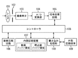
図1において、101はレンズであり、図示していない被写体像を結像する。102は絞り機構であり、レンズ101からの入射光量を調節する。103は撮像素子あり、レンズ101から絞り機構102を通って入射した光信号を電気信号に変換する。104はアナログ・デジタル変換器(A/D変換器)であり、撮像素子103によるアナログ信号をデジタル信号に変換する。105はカメラ信号処理回路であり、A/D変換器104のデジタル信号に対して設定されたホワイトバランス(WB)などの処理を施す。
In FIG. 1,
106は画像圧縮回路であり、画像データをJPEGなどの圧縮アルゴリズムを用いて圧縮する。107は内部記憶装置(RAM)であり、動画データ用の動画バッファ領域と静止画用の静止画バッファ領域とを備えていて、撮影時にカメラ信号処理回路105から出力されたデータを一時的に記憶する。
An
108はコントローラであり、図示していないメモリ(ROM)に記録されたソフトウェアに従い装置の各回路を制御する。109は記録媒体であり、RAM107上に一時的に記憶されているデータをファイル形式で保存するメモリカードやディスクなどである。110は書き込み処理部であり、外部記録媒体109へのデータ書き込みを行う。本実施の形態では、外部記録媒体109に動画データと静止画データとを混在させたファイル形式で記録する。
A
この外部記録媒体109にはCF(Compact Flash)カードを用いる。本実施の形態では、外部記録媒体109の記憶領域は、512バイトを1セクタとして各セクタに対して論理ブロックアドレス(LBA(Logical Block Address))が割り当てられているものとする。
As this
ファイルシステムにはFAT(File Allocation Table)を使用し、複数のセクタからなるクラスタ単位でデータを管理する。また、動画撮影中に静止画撮影する場合の記録は、RIFF(Resource Interchange File Format)に準拠したファイル形式で記録する。 A FAT (File Allocation Table) is used for the file system, and data is managed in units of clusters composed of a plurality of sectors. In addition, recording when shooting a still image during moving image recording is performed in a file format compliant with RIFF (Resource Interchange File Format).
図2は、本実施の形態における撮像装置の正面と背面の一例を示す図である。
図2において、動画撮影SW201は、動画撮影用に設けられたスイッチであって、半押しで動画撮影準備を開始し、全押しで動画撮影を開始する。また、静止画撮影SW202は、静止画撮影用に設けられたスイッチである。本実施の形態において、動画撮影SW201、及びこの動画撮影SW201に応じて動作する各機能を動画撮影手段と称する。また、静止画撮影SW202、及びこの静止画撮影SW202に応じて動作する各機能を動画静止画撮影手段と称する。
FIG. 2 is a diagram illustrating an example of a front surface and a back surface of the imaging apparatus according to the present embodiment.
In FIG. 2, a moving
203はレンズ鏡胴である。204はモードスイッチであり、動画・静止画撮影モードを設けてもよいし、動画撮影モードでは静止画撮影を可能とするように設定してもよい。205は十字キーボタンであり、モニタに表示されるメニューを操作するのに用いる。206はメニューボタンであり、撮像装置に備えられたアプリケーションを起動するのに用いる。
207は決定ボタン、208はキャンセルボタンであり、これらのボタン207及び208は、いずれもモニタに表示されるメニューを操作するのに用いる。209はモニタであり、撮影結果やメニューを表示する。
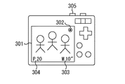
図3は、図2に示した本実施の形態の撮像装置を用いて動画撮影と静止画撮影を同時に行う際の操作イメージの一例を示す図である。
図3において、301は、撮影中の被写体を表示するモニタである。302は、動画撮影中であることを示す動画アイコンである。また、303は動画撮影経過時間を示す経過時間アイコンである。
FIG. 3 is a diagram illustrating an example of an operation image when the moving image shooting and the still image shooting are simultaneously performed using the imaging apparatus according to the present embodiment illustrated in FIG. 2.
In FIG. 3,
304は、静止画撮影可能な枚数を示す枚数アイコンであり、静止画バッファサイズの余裕分から算出される撮影可能枚数と、記憶媒体に撮影可能な枚数のうち少ない方の値を表示する。前者の場合は静止画撮影の間隔をおけばバッファ内のデータ処理が行われ撮影可能枚数が増加する。そこで、本実施の形態においては前者の場合と後者の場合で表示色を変えるなど、どちらの状況であるかユーザーが識別できるようにしている。305は静止画撮影用のスイッチであり、枚数アイコン304で残り撮影枚数が0でなければ静止画撮影が行われる。
A
図4は、本実施の形態における撮像装置で、動画データと静止画データとをファイルへ記録した場合のイメージの一例を示す図である。
図4において、動画バッファ401、静止画バッファ402は撮像装置の内部メモリ領域であって、内部記憶装置(RAM)107に存在する。
FIG. 4 is a diagram illustrating an example of an image when moving image data and still image data are recorded in a file in the imaging apparatus according to the present embodiment.
In FIG. 4, a moving
動画バッファ401には、オーディオデータ403とビデオフレームデータ404とからなる動画データを格納する。また、静止画バッファ402には、静止画データを格納する。本実施の形態では、静止画データはヘッダ部405、ボディ部406、サムネイル部407で構成するExif形式で格納されるものとする。
The moving
RIFF(Resource Interchange File Format)ファイル408は、動画データと静止画データとを混在させて記録するファイルである。RIFFファイル形式とは、さまざまなリソースを1つのファイルで管理するためのファイル形式である。このRIFFファイル形式は、新しいフォーマットのリソースができても基本構造の互換性が保たれる構造を特徴としている。本実施の形態で利用するRIFFファイルはヘッダ部409、データ部410、動画用のINDEX部411、静止画用のINDEX部412から構成される。
A RIFF (Resource Interchange File Format) file 408 is a file that records a mixture of moving image data and still image data. The RIFF file format is a file format for managing various resources in one file. The RIFF file format features a structure that maintains basic structure compatibility even when new format resources are created. The RIFF file used in this embodiment includes a
413は動画データであり、動画バッファ401からRIFFファイル408に記録されていることを示す。414は静止画データであり、静止画バッファ402からRIFFファイル408に記録されていることを示す。
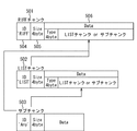
図5は、一般的なRIFFファイル形式の階層的なチャンク構造の一例を示す図である。
図5において、RIFFファイル形式は、RIFFチャンク501、LISTチャンク502、サブチャンク503を構成要素として有し、各チャンクはID部504、サイズ部505、データ部506を有している。
FIG. 5 is a diagram illustrating an example of a hierarchical chunk structure of a general RIFF file format.
In FIG. 5, the RIFF file format has a
ID部504は、チャンクのタイプを識別するための4byte領域(FOURCCコード)である。RIFFチャンクであればフォームタイプ(例えば、図7における'AVI'チャンク701)が、LISTチャンクであればリストタイプ(例えば、図7における'movi'チャンク704)が格納される。サイズ部505は、チャンクのデータサイズを示す4byte領域である。
The
データ部506には、データまたは階層化されるチャンクが格納される。ここには、任意のLISTチャンク及びサブチャンクを格納することができる。この構造により、RIFFファイルは、ID、サイズ、タイプを順次検索することにより、目的とするデータを取得することが可能となっている。
The
図6は、本実施の形態で利用するAVIファイルを拡張したRIFFファイル形式におけるチャンク構造の一例を示す図である。
図6において、RIFFチャンク601のフォームタイプは'AVI'で、この下にLIST(hdrl)チャンク602(リストタイプ'hdrl')、ダミーサブチャンク603(タイプ'JUNK')、LIST(movi)チャンク604(リストタイプ'movi')、動画インデックスサブチャンク(idx1)605(タイプ'idx1')、静止画インデックスサブチャンク(idxP)606(タイプ'idxP')の各ブロックがある。
FIG. 6 is a diagram showing an example of a chunk structure in the RIFF file format obtained by extending the AVI file used in the present embodiment.
In FIG. 6, the form type of
LIST(hdrl)チャンク602には、AVIファイルのヘッダ部分が記録され、'avih'サブチャンク607や、'strl'サブチャンク608などをもつ。'avih'サブチャンク607は、AVIファイル全体の情報を管理する構造体(AVIMAINHEADER)を格納する。'strl'サブチャンク608は、ストリーム情報を管理する構造体(AVISTREAMHEADER)とビデオフレームデータ、オーディオデータなどを管理する構造体(BITMAPINFO WAVEFORMATEX)とを格納する。
The LIST (hdrl)
JUNKサブチャンク603には、データ格納領域をファイルシステムのクラスタ境界に合わせるために、ダミーデータが記録される。LIST(movi)チャンク604には、撮影した動画を構成するオーディオデータ609、ビデオフレームデータ610が格納される。さらに本実施の形態のLIST(movi)チャンク604には、動画ファイルとしての非認識領域に静止画データチャンク611を記録する。
In the
静止画データチャンク611は、同一の静止画ファイルのデータであっても複数のチャンクに分割して記録されていることもある。動画インデックスサブチャンク(idx1)605には、LIST(movi)チャンク604に格納されたオーディオデータ609、ビデオフレームデータ610のデータ位置、データサイズ、再生データ順序の情報が記録される。
The still
静止画インデックスサブチャンク(idxP)606には、静止画データチャンク611についての属性情報テーブル612が記録される。
In the still image index sub-chunk (idxP) 606, an attribute information table 612 for the still
属性情報テーブル612には、静止画ファイル番号情報613と、このファイル番号に対応する静止画データチャンクのデータ記録位置及びデータサイズの情報614とが管理される。データ記録位置としては、例えばLIST(movi)チャンク604からのオフセット値を用いる。
The attribute information table 612 manages still image
図7は、本実施の形態の記録方法により静止画データを記録した場合の一例を示し、記録状況の結果の一例を示す図である。
図7において、データ先頭部701は、LIST(movi)チャンク604の先頭を示す。動画データ702は、オーディオデータチャンクまたはビデオフレームデータチャンクで構成される動画データを示す。
FIG. 7 is a diagram illustrating an example of a case where still image data is recorded by the recording method of the present embodiment, and an example of a result of a recording state.
In FIG. 7, the
クラスタ境界703は、本実施の形態で利用するFATファイルシステムのクラスタ境界を示す。記録データはクラスタ単位(例えば1クラスタが128セクタ、1セクタが512byteであれば、64Kbyteの領域サイズ)で管理される。ところが、動画データの大きさはセクタ・クラスタ単位を意識したものではないため、各動画データの先頭はほとんどの場合、クラスタ境界と一致しない。
A
第1の静止画データA704、第2の静止画データA705は、1枚の静止画ファイルのデータを分割して記録したデータチャンクを示す。これら静止画データA704、705のデータサイズはクラスタサイズの整数倍に合わせる。
The first still image data A704 and the second still image data A705 indicate data chunks obtained by dividing and recording data of one still image file. The data size of the still
ダミーデータ706は、静止画データを記録する直前のクラスタ領域内の非記録領域に記録するダミーデータを示す。これにより、静止画データの記録位置はクラスタ境界に合わせることができる。また、ダミーデータ706は、静止画データ記録後の動画データの記録位置をクラスタ境界に合わせるためのダミーデータでもある。
The
以上のように静止画データが記録されれば、静止画ファイルの分離はFATテーブルを操作することによるクラスタチェーンのつなぎ換えで実現することができる。 If still image data is recorded as described above, separation of still image files can be realized by switching cluster chains by operating a FAT table.
以上に説明した記録状況を実現するための、動画バッファと静止画バッファとからデータを書き込む方法を説明する。本実施の形態では、一定の秒数分の動画データ(以降、動画書き込み単位と呼ぶ)のデータ書き込みを行った後に、一定サイズの静止画データ(以降、静止画書き込み単位と呼ぶ)の書き込みを行う。 A method of writing data from the moving image buffer and the still image buffer for realizing the recording state described above will be described. In this embodiment, after writing data of moving image data for a certain number of seconds (hereinafter referred to as a moving image writing unit), writing of still image data of a certain size (hereinafter referred to as a still image writing unit) is performed. Do.
そして、本実施の形態では、すでにメディアに対するデータ記録履歴があってデータ書き込み速度が既知である状況を想定する。したがって、静止画書き込み単位データサイズは、静的に定まる動画書き込み単位データの取り得る最大データサイズ(最悪値)と、動画データ書き込み間隔と、データ書き込み速度とから以下のように算出される。
(静止画書き込み単位データサイズ [byte])
=(動画データ書き込み間隔[sec])*(書き込み速度[byte/sec])−(動画書き込み単位の最大データサイズ[byte])。
In the present embodiment, it is assumed that there is already a data recording history for the medium and the data writing speed is known. Therefore, the still image writing unit data size is calculated as follows from the maximum data size (worst value) that can be taken by the statically determined moving image writing unit data, the moving image data writing interval, and the data writing speed.
(Still image writing unit data size [byte])
= (Movie data writing interval [sec]) * (Writing speed [byte / sec])-(Maximum data size [byte] of movie writing unit).
図8は、書き込み処理部110の構成例を示すブロック図である。
図8において、入力キーコントローラ801は、動画撮影ボタンや静止画撮影ボタンなどからの入力イベントを処理し、撮影タスク802へ通知する。撮影タスク802は、動画撮影コントローラ803、静止画撮影コントローラ804を制御する。また、撮影開始時には、動画バッファ805、静止画バッファ806、インデックスバッファ807、動画バッファ監視タスク808、書き込みタスク809を初期化する。撮影終了時には、書き込みタスク809へバッファフラッシュを指示する。
FIG. 8 is a block diagram illustrating a configuration example of the
In FIG. 8, an input
動画撮影コントローラ803は、撮影タスク802からの指示を受け、動画撮影による信号処理を行う。信号処理により得られたオーディオデータとビデオフレームデータは動画バッファ805に格納し、動画バッファ監視タスク808へオーディオデータ生成完了イベントとビデオフレームデータ生成完了イベントを通知する。
The moving
静止画撮影コントローラ804は、撮影タスク802からの指示を受け静止画撮影による信号処理を行う。この信号処理により得られた静止画データは静止画バッファ806に格納する。動画バッファ805は、動画撮影コントローラ803により生成される動画データが格納される。静止画バッファ806は、静止画撮影コントローラ804により生成される静止画データが格納される。
The still image shooting controller 804 receives an instruction from the
インデックスバッファ807は、書き込みタスク809により書き込まれる動画データチャンク及び静止画データチャンクのデータ位置やサイズなどの属性情報が格納される。動画バッファ監視タスク808は、動画撮影コントローラ803からのデータ生成完了イベントを受けて動画バッファ805をチェックする。動画バッファ内に一定フレーム数のデータが存在すれば、書き込みタスク809へ動画データ書き込み要求イベントを通知する。
The
書き込みタスク809は、動画バッファ監視タスク808から動画データ書き込み要求イベントを受けて、ファイルシステム810への動画データ及び静止画データのチャンク書き込み処理を行う。書き込んだデータチャンクに関するインデックス情報はインデックスバッファ807に格納する。このインデックス情報は、撮影終了時にファイルの構成要素である動画用インデックス部と静止画用インデックス部の作成のために参照される。ファイルシステム810では、ファイルへの書き込み処理を行う。
The
次に、図9−1〜9−6のフローチャートを用いて、本実施の形態での一連の動画データ・静止画データの書き込み処理手順を説明する。
図9−1は、撮影タスク802の動画・静止画の同時撮影処理手順の一例を示すフローチャートである。
図9−1において、ステップS101は、ユーザーによる撮影を待つ撮影待ち状態である。ステップS102では、入力キーコントローラ801から動画撮影準備キーイベントを受信する。
Next, a series of moving image data / still image data write processing procedures according to the present embodiment will be described with reference to the flowcharts of FIGS. 9-1 to 9-6.
FIG. 9A is a flowchart illustrating an example of the procedure of the simultaneous shooting process of the moving image / still image of the
In FIG. 9A, step S101 is a shooting wait state waiting for shooting by the user. In step S102, a moving image shooting preparation key event is received from the input
ステップS103では、撮影時のメディアの空き容量をチェックする。ステップS104では、ピント固定処理(AF処理)を行い、ピントが固定されたらステップS105に遷移する。ステップS105は、動画撮影準備を行う動画撮影準備中状態である。 In step S103, the free space of the media at the time of shooting is checked. In step S104, a focus fixing process (AF process) is performed. If the focus is fixed, the process proceeds to step S105. Step S105 is a moving image shooting preparation state in which moving image shooting preparation is performed.
ステップS106では、入力キーコントローラ801から動画撮影開始キーイベントを受信する。ステップS107では、動画バッファ805と静止画バッファ806とインデックスバッファ807とを初期化する。
In step S106, a moving image shooting start key event is received from the input
ステップS108では、書き込みタスク809へ初期化イベントを通知する。ステップS109では、動画撮影コントローラ803を制御して動画キャプチャを開始する。ステップS110では、動画バッファ監視タスク808へ初期化イベントを通知して、ステップS111へ遷移する。
In step S108, the
ステップS111は、動画撮影を行う動画撮影中状態である。ステップS112では、動画撮影が継続されるかチェックする。このチェックの結果、動画撮影を継続ならばステップS113に進み、動画撮影中状態において入力キーコントローラ801から静止画撮影キーイベントを受信する。
Step S111 is a moving image shooting state in which moving image shooting is performed. In step S112, it is checked whether moving image shooting is continued. If the result of this check is that movie shooting is to continue, the process proceeds to step S113, and a still image shooting key event is received from the input
ステップS114では、静止画バッファ806に静止画撮影のための空き領域があるか否かをチェックする。このチェックの結果、空き領域があるならばステップS115に進み、静止画撮影コントローラ804を制御して静止画キャプチャを開始し、ステップS111へ遷移する。一方、ステップS114のチェックの結果、空き領域が無ければステップS116に進み、静止画バッファに空きが無いため静止画撮影ができないことをワーニング表示してステップS111へ遷移する。
In step S114, it is checked whether the
また、ステップS112のチェックの結果、動画撮影を継続しないならばステップS117に進み、動画撮影中状態において入力キーコントローラ801から動画撮影終了キーイベントを受信する。次に、ステップS118に進み、動画撮影コントローラ803を制御して動画キャプチャを終了する。その後、ステップS119に進み、書き込みタスク809へバッファフラッシュ指示イベントを通知し、ステップS101へ遷移する。
If the result of the check in step S112 is that movie shooting is not continued, the process proceeds to step S117, and a movie shooting end key event is received from the input
図9−2は、動画バッファ監視タスク808の処理手順の一例を示すフローチャートである。
図9−2において、ステップS201は、タスク初期化待ち状態である。初期化処理が開始されるとステップS202に進み動画バッファ監視タスク初期化イベントを受信すると、ステップS203へ遷移し、動画撮影コントローラ803による動画書き込み単位のデータ生成を待つ、動画書き込み単位データ生成待ち状態となる。
FIG. 9-2 is a flowchart illustrating an example of a processing procedure of the moving image
In FIG. 9B, step S201 is in a task initialization waiting state. When the initialization process is started, the process proceeds to step S202, and when a moving image buffer monitoring task initialization event is received, the process proceeds to step S203, where the moving
動画書き込み単位データ生成処理が開始されると、ステップS204に進み、動画撮影コントローラ803からビデオフレームデータ生成完了イベントと、オーディオデータ生成完了イベントとを受信する。
When the moving image writing unit data generation process is started, the process proceeds to step S204, where a video frame data generation completion event and an audio data generation completion event are received from the moving
次に、ステップS205に進み、動画書き込み単位データがバッファに格納されているか否かをチェックする。このチェックの結果、単位データがあるならば、ステップS206に進み、書き込みタスク809へ動画データ書き込み要求イベントを通知して、その後ステップS203の状態へ遷移する。一方、ステップS205のチェックの結果、単位データが無ければステップS206の処理をジャンプしてステップS203の状態へ直接遷移する。
In step S205, it is checked whether moving image writing unit data is stored in the buffer. As a result of this check, if there is unit data, the process proceeds to step S206, where the
図9−3は、書き込みタスク809の処理手順の一例を示すフローチャートである。
図9−3において、ステップS301は、タスク初期化待ち状態である。
タスク初期化処理が開始されると、ステップS302で撮影タスク802から書き込みタスク初期化イベントを受信する。次に、ステップS303に進み、書き込みタスクの初期化処理を行う。この初期化処理に関しては、図9−6のフローチャートを参照しながら後で詳細に説明する。次のステップS304は、書き込み待ち状態である。
FIG. 9C is a flowchart illustrating an example of the processing procedure of the
In FIG. 9C, step S301 is in a task initialization waiting state.
When the task initialization process is started, a writing task initialization event is received from the
書き込みが行われた場合にはステップS305に進み、動画撮影中かどうか否かをチェックする。このチェックの結果、動画撮影中ならば、ステップS306に進み、書き込みタスク809から動画データ書き込み要求イベントを受信する。本実施の形態では、まず動画データの書き込みから優先的に行うものとする。次に、ステップS307に進み、動画書き込み単位のフレーム数を指定して動画データの書き込み処理を行う。この動画データ書き込み処理に関しては、図9−4のフローチャートを参照しながら後で詳細に説明する。
If writing has been performed, the process proceeds to step S305, where it is checked whether or not moving image shooting is in progress. If the result of this check is that moving image shooting is in progress, the process advances to step S 306 to receive a moving image data write request event from the
次に、ステップS308に進み、静止画バッファ806内にデータがあるか否かをチェックする。このチェックの結果、データが無ければ、ステップS304へ遷移する。一方、ステップS308のチェックの結果、静止画バッファ806内にデータがあれば、ステップS309に進み、静止画書き込み単位のデータが書き込み対象の静止画ファイルの終端を含むか否かをチェックする。本実施の形態では、静止画書き込み単位はファイルシステムのクラスタサイズの整数倍となるように設定している。
In step S308, it is checked whether there is data in the
このチェックの結果、静止画ファイルの終端を含むならば、ステップS310に進み、静止画ファイル終端部までのデータを取得する。一方、ステップS309のチェックの結果、静止画ファイルの終端を含まないならばステップS311に進み、静止画書き込み単位のデータを取得する。 If the result of this check is that the end of the still image file is included, the process proceeds to step S310 to acquire data up to the end of the still image file. On the other hand, as a result of the check in step S309, if the end of the still image file is not included, the process proceeds to step S311 to acquire still image writing unit data.
ステップS310またはステップS311の処理を終了したら、次にステップS312に進み、ステップS310またはステップS311で取得した静止画データの書き込み処理を行い、ステップS304へ遷移する。この静止画データ書き込み処理に関しては、図9−5のフローチャートを参照しながら、後で詳細に説明する。 When the process of step S310 or step S311 is completed, the process proceeds to step S312, where the still image data acquired in step S310 or step S311 is written, and the process proceeds to step S304. The still image data writing process will be described in detail later with reference to the flowchart of FIG. 9-5.
一方、ステップS305のチェックの結果、動画撮影中でなかったらステップS313に進み、撮影タスク802からバッファフラッシュ指示イベントを受信する。次に、ステップS314に進み、動画バッファ805に格納されたすべての動画フレーム数を取得する。次に、ステップS315に進み、ステップ314で取得した動画フレーム数を指定して動画データの書き込み処理を行う。
On the other hand, if the result of the check in step S305 is that moving image shooting is not in progress, the flow advances to step S313 to receive a buffer flash instruction event from the
次に、ステップS316に進み、静止画バッファ806内にデータがあるか否かをチェックする。このチェックの結果、データが無ければ、ステップS301へ遷移する。一方、ステップS316のチェックの結果、データがあれば、ステップS317に進み、静止画バッファ806内の静止画ファイルデータについて、ファイル終端までのデータを取得する。本実施の形態においては、バッファフラッシュ処理の開始時には、フラッシュ処理以前に書き込みを行っていた静止画ファイルデータについて、ファイル終端までの残りのサイズを取得することになる。
In step S316, it is checked whether there is data in the
次に、ステップS318に進み、ステップS317で取得したデータの書き込み処理を行う。その後、ステップS319に進み、静止画バッファ内にデータが残っているか否かをチェックする。このチェックの結果、データが残っていればステップS317に進み、次の静止画ファイルの書き込み処理を行う。 Next, the process proceeds to step S318, and the data acquired in step S317 is written. Thereafter, the process proceeds to step S319, where it is checked whether data remains in the still image buffer. As a result of the check, if data remains, the process proceeds to step S317, and the next still image file is written.
一方、ステップS319のチェックの結果、データが残っていなければ、すべての静止画ファイルデータ書き込みが終了したため、ステップS320に進んで書き込みタスク終了処理を行い、その後ステップS301へ遷移して初期化待ちとなる。ステップS320で行う終了処理に関しては、図9−6のフローチャートを参照しながら後で詳細に説明する。 On the other hand, if no data remains as a result of the check in step S319, writing of all still image file data has been completed, so the process proceeds to step S320 to perform a write task end process, and then the process proceeds to step S301 to wait for initialization. Become. The termination process performed in step S320 will be described in detail later with reference to the flowchart of FIG. 9-6.
図9−4(a)、(b)は、ステップS306で行われる動画データ書き込み処理手順の一例を示すフローチャートである。
図9−4(a)に示したように、処理が開始されると、先ずステップS401では、動画フレームデータを書き込みためのインデックス値を初期化する。次に、ステップS402では、動画フレームデータの書き込み処理を行う。ステップS402の処理の詳細については、図9−4(b)のフローチャートで説明する。次に、ステップS403では、前記インデックス値を更新する。
FIGS. 9-4 (a) and (b) are flowcharts showing an example of the moving image data writing processing procedure performed in step S306.
As shown in FIG. 9-4 (a), when the process is started, first, in step S401, an index value for writing moving image frame data is initialized. In step S402, moving image frame data is written. Details of the process of step S402 will be described with reference to the flowchart of FIG. In step S403, the index value is updated.
次に、ステップS404に進み、指定された動画フレーム数を書き込んだか否かをチェックする。ここで、指定された動画フレーム数とは、動画撮影時では動画書き込み単位のフレーム数であり、バッファフラッシュ時ではバッファ内のすべてのフレーム数となる。このチェックの結果、指定された動画フレーム数を書き込んでいなければ、ステップS402の処理へ戻り、ステップS404のチェックの結果、指定された動画フレーム数を書き込んでいれば、終了となる。 In step S404, it is checked whether the designated number of moving image frames has been written. Here, the designated number of moving image frames is the number of frames in a moving image writing unit at the time of moving image shooting, and is the number of all frames in the buffer at the time of buffer flash. As a result of this check, if the designated number of moving image frames has not been written, the process returns to step S402. If the result of the check in step S404 shows that the designated number of moving image frames has been written, the process ends.
次に、図9−4(b)を参照しながらステップS402のフレーム書き込み処理について詳細を説明する。
処理が開始されると、先ずステップS405において、動画バッファから1秒分のオーディオデータを取得する。次に、ステップS406に進み、ステップS405で取得したオーディオデータをチャンクに書き込む。
Next, details of the frame writing process in step S402 will be described with reference to FIG. 9-4 (b).
When the processing is started, first, in step S405, audio data for one second is acquired from the moving image buffer. Next, it progresses to step S406 and the audio data acquired by step S405 are written in a chunk.
次に、ステップS407に進み、書き込んだオーディオデータチャンクの属性情報(データ位置、サイズ)をインデックスバッファ807へ記録する。次に、ステップS408に進み、動画バッファ805からフレームレートに相当するビデオフレームデータを取得する。
In step S407, the attribute information (data position, size) of the written audio data chunk is recorded in the
次に、ステップS409に進み、ビデオフレームデータ書き込みのためのインデックス値を初期化する。その後、ステップS410に進み、ステップS408で取得したビデオフレームデータをチャンクに書き込む。その後、ステップS411に進み、書き込んだビデオフレームデータチャンクの属性情報(データ位置、サイズ)をインデックスバッファ807へ記録する。
In step S409, an index value for writing video frame data is initialized. Thereafter, the process proceeds to step S410, and the video frame data acquired in step S408 is written in the chunk. Thereafter, the process proceeds to step S411, and the attribute information (data position, size) of the written video frame data chunk is recorded in the
次に、ステップS412に進み、前記インデックス値を更新する。その後、ステップS413において、1秒分のビデオフレームデータの書き込みが終了したか否かをチェックする。このチェックの結果、終了していなければ、ステップS410の処理へ戻る。また、ステップS413のチェックの結果、終了していれば、フレーム書き込み処理は終了する。 In step S412, the index value is updated. Thereafter, in step S413, it is checked whether or not the writing of video frame data for one second has been completed. As a result of the check, if not completed, the process returns to step S410. On the other hand, if it is determined in step S413 that the process has been completed, the frame writing process ends.
図9−5は、ステップS308の静止画データ書き込み処理手順の一例を示すフローチャートである。
図9−5に示したように、処理が開始されると、先ずステップS501では、ダミーチャンクの書き込みを行う。本実施の形態では、静止画データの書き込み以前に動画データチャンクの書き込み処理を行っている。
FIG. 9-5 is a flowchart illustrating an example of a still image data writing process procedure in step S308.
As shown in FIG. 9-5, when processing is started, first, in step S501, a dummy chunk is written. In the present embodiment, the moving image data chunk writing process is performed before the still image data is written.
ところが、図8に示したように、動画データチャンクの書き込み終了位置はクラスタ境界に合っていない。そこで、このステップS501では、静止画データチャンクの書き込み開始位置をファイルシステムのクラスタ境界に合わせるためにダミーチャンクの書き込みを行っている。 However, as shown in FIG. 8, the writing end position of the moving image data chunk does not match the cluster boundary. Therefore, in this step S501, a dummy chunk is written in order to align the write start position of the still image data chunk with the cluster boundary of the file system.
次に、ステップS502に進み、書き込み指定された静止画データが静止画ファイルの終端を含むか否かをチェックする。このチェックの結果、静止画ファイルの終端を含むならば、ステップS503に進み、書き込み指定された静止画ファイル終端までの静止画データをチャンクに書き込む。一方、ステップS502のチェックの結果、静止画ファイルの終端を含まなければ、ステップS505に進んで書き込み指定された静止画データをチャンクに書き込む。 In step S502, it is checked whether the still image data designated for writing includes the end of the still image file. If the result of this check is that the end of the still image file is included, the process advances to step S503 to write still image data up to the end of the still image file designated for writing in the chunk. On the other hand, if it is determined in step S502 that the end of the still image file is not included, the process proceeds to step S505 to write the still image data designated for writing in the chunk.
ステップS305で説明したように、書き込み指定された静止画データはクラスタサイズの整数倍となっているので、本ステップでの書き込み後にはダミーチャンクを書き込む必要は無い。 As described in step S305, since the still image data designated for writing is an integral multiple of the cluster size, it is not necessary to write a dummy chunk after writing in this step.
次に、ステップS504に進み、ダミーチャンクの書き込みを再び行う。ステップS503で書き込みを行った静止画データチャンクは、ファイルシステムのクラスタサイズとは無関係なデータサイズとなっている。そこで、このステップS504で、静止画データの記録領域をファイルシステムのクラスタサイズの整数倍に合わせるためにダミーチャンクの書き込みを行っている。 In step S504, the dummy chunk is written again. The still image data chunk written in step S503 has a data size that is unrelated to the cluster size of the file system. In step S504, dummy chunks are written in order to match the still image data recording area to an integer multiple of the file system cluster size.
次に、ステップS506に進み、書き込んだ静止画データチャンクの属性情報(静止画ファイル番号、データ位置、サイズ)をインデックスバッファ807へ記録する。
In step S506, the attribute information (still image file number, data position, size) of the written still image data chunk is recorded in the
図9−6(a)は、図9−3におけるステップS303の書き込みタスク初期化処理の一例を示すフローチャートであり、図9−6(b)は、ステップS319の書き込みタスク終了処理の一例を示すフローチャートである。
図9−6(a)に示したように、処理が開始されると、先ずステップS601では、撮影データを書き込むRIFFファイルをオープンする。次に、ステップS602に進み、ファイルのヘッダを生成する。次に、ステップS603に進み、動画データ、静止画データを書き込む'movi'チャンクをオープンする処理を行い、書き込みタスク初期化処理を終了する。
FIG. 9-6 (a) is a flowchart showing an example of the write task initialization process in step S303 in FIG. 9-3, and FIG. 9-6 (b) shows an example of the write task end process in step S319. It is a flowchart.
As shown in FIG. 9-6 (a), when the process is started, first, in step S601, a RIFF file to which shooting data is written is opened. In step S602, a file header is generated. In step S603, a 'movi' chunk for writing moving image data and still image data is opened, and the writing task initialization process is terminated.
図9−6(b)に示したように、処理が開始されると、先ずステップS604では、'movi'チャンクをクローズする。次に、ステップS605に進み、インデックスバッファ807に記録された動画データチャンクと静止画データチャンクの属性情報を読み込む。次に、ステップS606に進み、動画用インデックスと静止画用インデックスとを作成して、ステップS605で読み込んだ属性情報を書き込む。その後、ステップS607に進み、ファイルをクローズする処理を行い、書き込みタスク終了処理を終了する。
As shown in FIG. 9-6 (b), when the process is started, first, in step S604, the 'movi' chunk is closed. In step S605, the attribute information of the moving image data chunk and the still image data chunk recorded in the
以上に説明した処理によって、動画データと静止画データをファイルへ書き込んだ場合のバッファ利用状況を図10に例示する。
図10は、本実施の形態における動画データと静止画データをファイルへ書き込んだ場合のバッファ利用状況を示す図である。
図10において、線図1001は、撮影中の動画バッファ内のデータ状況を示す。1002は、動画バッファの最大バッファサイズ[byte]を示す。
FIG. 10 exemplifies a buffer usage situation when moving image data and still image data are written to a file by the processing described above.
FIG. 10 is a diagram showing a buffer usage situation when moving image data and still image data are written in a file according to the present embodiment.
In FIG. 10, a diagram 1001 shows a data state in the moving image buffer during shooting.
1003は動画書き込み単位データであり、動画書き込み単位のフレーム数に相当する動画データを示している。この動画書き込み単位データ1003が動画バッファ内に格納されると、書き込みタスクへ動画データ書き込みイベントが通知される。1004は動画書き込みタイミングであり、書き込みタスクへ動画データ書き込みイベントを通知されるタイミングを示している。
線図1005は、撮影中の静止画バッファ内のデータ状況を示す。1006は、静止画バッファの最大バッファサイズ[byte]を示す。1007は生成静止画データであり、動画撮影中の静止画撮影により静止画バッファに静止画データが生成された様子を示している。1008は静止画書き込みタイミングであり、書き込みタスクが動画データ書き込み処理を終え、静止画データ書き込み処理を開始するタイミングを示している。
A diagram 1005 shows a data state in the still image buffer during shooting.
1009は書き込み静止画データであり、動画データ書き込み後にファイルへ書き込まれる静止画書き込み単位のデータを示す。以上に説明した処理を行うことによって、本実施の形態においては動画データ書き込みの合間に静止画データの書き込みを実現できるようにしている。
次に、本実施の形態で記録したファイルから静止画ファイルを分離する方法について説明する。
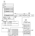
図11は、本実施の形態における記録ファイルから静止画ファイルを分離するアプリケーションのユーザーインタフェースの一例を示す図である。
Next, a method for separating a still image file from a file recorded in the present embodiment will be described.
FIG. 11 is a diagram illustrating an example of a user interface of an application that separates a still image file from a recording file according to the present embodiment.
図11において、画像1101は、記録ファイルを代表するレビュー画像を示す。アイコン1102は、記録ファイル内に静止画データが混在していることを示す。メニュー1103は、記録ファイルから静止画ファイルを分離するかどうか否かをユーザーに問い合わせるメニュー項目である。ユーザーは、十字キーと決定ボタンにより分離することを決定する。
In FIG. 11, an
図12は、本実施の形態におけるファイル内に記録されている静止画データを分離して静止画ファイルを分離する手順の一例を示す図である。
図12において、ファイル1201は、本実施の形態の記録方法により得られる動画データと静止画データとが混在するファイルである。テーブル1202は、ファイル内の静止画データチャンクの属性情報として、静止画番号と静止画データチャンク位置とデータサイズを管理しているテーブルである。
FIG. 12 is a diagram illustrating an example of a procedure for separating still image data by separating still image data recorded in a file according to the present embodiment.
In FIG. 12, a
イメージ1203は、ファイル内に記録されている静止画データチャンクから作成される静止画ファイルのイメージ図である。本実施の形態では、静止画番号"PICT0002"のファイルは、データサイズがb1[byte]の静止画データ格納領域とデータサイズがb2[byte]の静止画データ格納領域から構成されている。 An image 1203 is an image diagram of a still image file created from a still image data chunk recorded in the file. In the present embodiment, the file with the still picture number “PICT0002” is composed of a still picture data storage area with a data size of b1 [bytes] and a still picture data storage area with a data size of b2 [bytes].
テーブル1204は、ファイルシステムのディレクトリ・ファイル管理テーブルである。ファイル1201から静止画ファイルを分離する場合には、このテーブル1204に分離対象の静止画ファイル(例えばPICT0002.JPG)を登録する。このとき、1205に示す開始クラスタには、静止画データが格納されているデータチャンクの先頭のクラスタ番号を指定する。そして、以降のデータ格納領域は1206に示すFATテーブルで管理させる。
A table 1204 is a file system directory / file management table. When separating a still image file from the
矢印1207は、クラスタチェーンのつなぎ換えによって2つの静止画データ記録クラスタ領域を結合している様子を示す。クラスタ領域とは、動画データと静止画データとを無関係に順次格納した場合には、静止画ファイルを分離するために、ファイルデータの読み書きを繰り返し行わなければならない。そのため、ファイルサイズが大きくなると分離のために多くの処理時間が必要となってしまう問題点が生じる。
An
しかし、以上に説明した本実施の形態では、ファイル内に記録された静止画データチャンクはクラスタ境界とクラスタサイズに合わせている。そのため、ファイル内でのデータ移動を行うことなく、クラスタチェーンのつなぎ換えによって静止画ファイルを作成することができるため、静止画ファイルを高速に分離することができる。 However, in the present embodiment described above, the still image data chunk recorded in the file is matched with the cluster boundary and the cluster size. Therefore, a still image file can be created by changing the cluster chain without performing data movement within the file, so that the still image file can be separated at high speed.
(第2の実施の形態)
以下に、動画データ書き込みの合間に行う静止画データ書き込みのデータサイズを、書き込み履歴からの予測に基づいて動的に決定する方法について説明する。本実施の形態では、動画書き込み単位のデータ書き込みを行った後に、次の動画書き込みタイミングまでに書き込めるデータサイズの予測を行い、静止画データを書き込む。
(Second Embodiment)
Hereinafter, a method of dynamically determining the data size of still image data writing performed between moving image data writing based on prediction from the writing history will be described. In the present embodiment, after writing data in units of moving image writing, the size of data that can be written is predicted by the next moving image writing timing, and still image data is written.
動画書き込み要求イベントは動画書き込み単位の秒数の動画データが生成されるごとに発行されるため、動画データ書き込みタイミングはほぼ指定秒数に従う。したがって、予測される静止画書き込み可能データサイズは、動画書き込みに要した動画データ書き込み時間とデータ書き込み速度の実測値を用いて、以下のように算出される。
(静止画書き込み可能データサイズ [byte])
={(動画書き込み単位秒数[sec])−(動画データ書き込み時間[sec])}*(書き込み速度[byte/sec])。
Since the moving image writing request event is issued every time moving image data of the number of seconds for moving image writing is generated, the moving image data writing timing almost follows the specified number of seconds. Accordingly, the predicted still image writable data size is calculated as follows using the measured values of the moving image data writing time and the data writing speed required for moving image writing.
(Still image writable data size [byte])
= {(Moving image writing unit seconds [sec]) − (moving image data writing time [sec])} * (writing speed [byte / sec]).
このとき、書き込み速度には直前の動画データ書き込み処理で得られる値を利用してもよいし、書き込み履歴の平均値を用いてもよい。書き込み処理部の構成及び、撮影タスク、動画バッファ監視タスクの処理は第1の実施の形態と同様である。 At this time, a value obtained by the immediately preceding moving image data writing process may be used as the writing speed, or an average value of the writing history may be used. The configuration of the writing processing unit and the processing of the shooting task and the moving image buffer monitoring task are the same as those in the first embodiment.
図13は、本実施の形態における、静止画データサイズを予測して書き込みを行う書き込みタスク809の処理手順の一例を示すフローチャートである。
図13に示したように、ステップS1301はタスク初期化待ち状態である。そして、処理が開始されるとステップS1302に進み、撮影タスク802から書き込みタスク初期化イベントを受信する。次に、ステップS1303に進み、書き込みタスクの初期化処理を行う。この初期化処理は第1の実施の形態と同様である。その後、ステップS1304へ遷移する。ステップS1304は、書き込み待ち状態である。
FIG. 13 is a flowchart illustrating an example of a processing procedure of the
As shown in FIG. 13, step S1301 is in a task initialization waiting state. When the process is started, the process advances to step S1302 to receive a write task initialization event from the
ステップS1304の書き込み待ち状態において、書き込みが発生するとステップS1305に進み、動画の撮影中か否かをチェックする。このチェックの結果、動画撮影中ならば、ステップS1306に進み、書き込み待ち状態において書き込みタスク802から動画データ書き込み要求イベントを受信する。
If writing occurs in the writing waiting state in step S1304, the process advances to step S1305 to check whether a moving image is being shot. If the result of this check is that moving image shooting is in progress, the process advances to step S1306 to receive a moving image data write request event from the
次に、ステップS1307に進み、静止画バッファ806内に静止画データがあるか否かをチェックする。このチェックの結果、静止画データがあればステップS1308に進み、書き込めるデータサイズの予測処理を行う。一方、ステップS1307のチェックの結果、静止画データが無ければ、ステップS1316に進み、動画バッファ内にあるすべてのデータフレーム数を指定して動画データ書き込み処理を行い、その後、ステップS1304の書き込み待ち状態へ遷移する。
In
前記ステップS1308の予測処理では、動画書き込み単位データの書き込み処理に要する時間と、書き込み速度の計測を開始する。その後、ステップS1309に進み、動画バッファ内にあるすべてのデータフレーム数を指定して動画データ書き込み処理を行う。ステップS1309で行う動画データの書き込み処理は、第1の実施の形態と同様である。次に、ステップS1310に進み、ステップS1308で開始した動画データ書き込みの計測を終了する。 In the prediction processing in step S1308, measurement of the time required for the writing processing of the moving image writing unit data and the writing speed are started. Thereafter, the process proceeds to step S1309, and the moving image data writing process is performed by designating all the data frames in the moving image buffer. The moving image data writing process performed in step S1309 is the same as that in the first embodiment. Next, proceeding to step S1310, the moving image data writing measurement started at step S1308 is terminated.
次に、ステップS1311に進み、次の動画データ書き込みタイミングまでに書き込むことができる静止画データサイズの予測値を前述の式により算出する。次に、ステップS1312において、ステップS1311で取得したサイズの静止画データが静止画ファイルの終端を含むか否かをチェックする。このチェックの結果、静止画ファイルの終端を含むならば、ステップS1313に進み、静止画ファイル終端部までのデータを取得する。 Next, the process proceeds to step S1311, and a predicted value of the still image data size that can be written by the next moving image data writing timing is calculated by the above formula. Next, in step S1312, it is checked whether or not the still image data of the size acquired in step S1311 includes the end of the still image file. If the result of this check is that the end of the still image file is included, the process advances to step S1313 to acquire data up to the end of the still image file.
一方、ステップS1312のチェックの結果、静止画ファイルの終端を含まないならば、ステップS1314に進み、ステップS1311で算出した予測書き込みサイズに収まる範囲でファイルシステムのクラスタサイズの整数倍となる最大のサイズの静止画データを取得する。 On the other hand, if the end of the still image file is not included as a result of the check in step S1312, the process proceeds to step S1314, and the maximum size that is an integral multiple of the file system cluster size within the range that fits in the predicted write size calculated in step S1311. Get the still image data.
ステップS1313またはステップS1314の処理を終了したら、ステップS1315に進む。ステップS1315では、ステップS1313またはステップS1314で取得した静止画データの書き込み処理を行う。そして、この静止画データの書き込み処理を終了したら、ステップS1304の書き込み待ち状態に戻る。 When the process of step S1313 or step S1314 is completed, the process proceeds to step S1315. In step S1315, the still image data acquired in step S1313 or step S1314 is written. When the still image data writing process is completed, the process returns to the writing wait state in step S1304.
一方、ステップS1305のチェックの結果、動画撮影中でなかったら、ステップS1317に進み、書き込み待ち状態において撮影タスク802からバッファフラッシュ指示イベントを受信する。次に、ステップS1318に進み、動画バッファ805に格納されたすべての動画フレーム数を取得する。その後、ステップS1319に進み、ステップS1318で取得した動画フレーム数を指定して動画データの書き込み処理を行う。
On the other hand, if the result of the check in step S1305 is that moving image shooting is not in progress, the flow advances to step S1317 to receive a buffer flash instruction event from the
次に、ステップS1320において、静止画バッファ806内に静止画データがあるか否かをチェックする。このチェックの結果、データが無ければ、ステップS1301の初期化待ち状態へ遷移する。また、ステップS1320のチェックの結果、静止画データがあれば、ステップS1321に進み、静止画バッファ806内の静止画ファイルデータについて、ファイル終端までのデータを取得する。バッファフラッシュ処理の開始時には、フラッシュ処理以前に書き込みを行っていた静止画ファイルデータについて、ファイル終端までの残りのサイズを取得することになる。
Next, in step S1320, it is checked whether there is still image data in the
次に、ステップS1322に進み、ステップS1321で取得した静止画データの書き込み処理を行う。次に、ステップS1323に進み、静止画バッファ内に静止画データが残っているか否かをチェックする。このチェックの結果、静止画データが残っていればステップS1321へ戻り、次の静止画ファイルの書き込み処理を行う。 Next, the process proceeds to step S1322, and the still image data acquired in step S1321 is written. In step S 1323, it is checked whether still image data remains in the still image buffer. If still image data remains as a result of this check, the process returns to step S1321 to write the next still image file.
一方、ステップS1323のチェックの結果、静止画データが残っていなければ、すべての静止画ファイルデータ書き込みが終了したため、ステップS1324へ遷移して書き込みタスクの終了処理を行う。この終了処理は第1の実施の形態と同様である。 On the other hand, if no still image data remains as a result of the check in step S1323, writing of all the still image file data has been completed, and the process proceeds to step S1324 to perform the writing task termination process. This termination process is the same as in the first embodiment.
以上に説明したように、本実施の形態によれば、動画データ書き込み後に次の動画データ書き込みタイミングまでに書き込むことができる静止画データサイズの予測を行い、予測値に従う静止画データ書き込みを行う。静止画書き込みデータサイズが実際の書き込み可能サイズよりも多めに予測された場合は、次の動画書き込みタイミングで動画バッファ内の全ての動画データを書き込むので、この場合に対応できるだけの動画バッファサイズを確保しておけばバッファオーバーフローは発生しない。この処理によって、データ書き込み処理を行わない時間帯を減らした効率的な書き込み処理を実現することができる。 As described above, according to the present embodiment, the still image data size that can be written by the next moving image data write timing after the moving image data is written is predicted, and the still image data is written according to the predicted value. If the still image write data size is predicted to be larger than the actual writable size, all the video data in the video buffer is written at the next video write timing, so a video buffer size that can handle this case is secured. If so, buffer overflow will not occur. With this process, it is possible to realize an efficient write process with a reduced time zone during which no data write process is performed.
(第3の実施の形態)
以下に、動画撮影中に静止画撮影を行う際にExifファイルのボディ部のみをファイルに記録する場合の、静止画ファイルの分離方法について図面を参照しながら説明する。
図14は、本実施の形態における、ファイル内に記録されている静止画データを分離してExif形式の静止画ファイルを分離する手順の一例を示す図である。
(Third embodiment)
Hereinafter, a method for separating still image files in the case where only the body portion of an Exif file is recorded in a file when still image shooting is performed during moving image shooting will be described with reference to the drawings.
FIG. 14 is a diagram illustrating an example of a procedure for separating still image data recorded in a file and separating an Exif format still image file in the present embodiment.
図14において、1401は、第1の実施の形態で説明した記録方法により得られる動画データと静止画データとが混在するファイルである。1402は、日付情報などを含むRIFFファイルのヘッダ部である。1403は、ファイル内の静止画データチャンクの属性情報として、静止画番号と静止画データチャンク位置とデータサイズとを管理しているテーブルである。
In FIG. 14,
イメージ1404は、ファイル内に記録されている静止画データチャンクから作成される静止画ファイルのイメージ図である。イメージ図1404内の1405は、ファイル1401から分離するExif静止画ファイルのボディ部である。イメージ図1404内のサムネイル部1406は、静止画ファイル分離時にボディ部1405から作成する。イメージ図1404内のExifヘッダ1407は、ファイル1401のヘッダ部1402から流用するヘッダ情報とサムネイル部1406とから作成する。
An
テーブル1408は、ファイルシステムのディレクトリ・ファイル管理テーブルである。ファイル1401から静止画ファイルを分離する場合には、このテーブルに分離対象の静止画ファイル(例えばPICT0002.JPG)を登録する。このとき、1409に示す開始クラスタには、作成したExifヘッダ1406のクラスタ番号を指定する。そして、以降のデータ格納領域は1410に示すFATテーブルで管理させる。
A table 1408 is a file system directory / file management table. When a still image file is separated from the
FATテーブル内の第1の要素1411は、作成したExifヘッダ1407が記録されているデータ領域である。第2の要素1412は、ファイル1401から分離した静止画ファイルボディ部1405が記録されているデータ領域である。矢印1413は、クラスタチェーンのつなぎ換えによって、別々のデータ領域に記録されている第1の要素1411と第2の要素1412のExifヘッダ部1407とボディ部1405とを結合している様子を示す。
A first element 1411 in the FAT table is a data area in which the created Exif header 1407 is recorded. A
以上に説明したように本実施の形態では、静止画ファイルのボディ部のみをファイルに記録して、ヘッダ情報、サムネイル情報は静止画ファイル分離時に作成する。そのため、ファイル内にヘッダ情報やサムネイル情報を含む静止画データを記録する場合よりも、記録するファイルのデータサイズを小さくすることができる。 As described above, in this embodiment, only the body portion of a still image file is recorded in the file, and header information and thumbnail information are created when the still image file is separated. Therefore, the data size of the file to be recorded can be made smaller than when still image data including header information and thumbnail information is recorded in the file.
(本発明に係る他の実施の形態)
前述した本発明の実施の形態における撮像装置を構成する各手段、並びに画像記録方法の各ステップは、コンピュータのRAMやROMなどに記憶されたプログラムが動作することによって実現できる。このプログラム及び前記プログラムを記録したコンピュータ読み取り可能な記録媒体は本発明に含まれる。
(Another embodiment according to the present invention)
Each means constituting the imaging apparatus and each step of the image recording method in the embodiment of the present invention described above can be realized by operating a program stored in a RAM or ROM of a computer. This program and a computer-readable recording medium recording the program are included in the present invention.
また、本発明は、例えば、システム、装置、方法、プログラムもしくは記録媒体等としての実施の形態も可能であり、具体的には、複数の機器から構成されるシステムに適用してもよいし、また、一つの機器からなる装置に適用してもよい。 Further, the present invention can be implemented as, for example, a system, apparatus, method, program, or recording medium, and can be applied to a system composed of a plurality of devices. Moreover, you may apply to the apparatus which consists of one apparatus.
なお、本発明は、前述した実施の形態の機能を実現するソフトウェアのプログラム(実施の形態では図9−1〜図9−6、図13に示すフローチャートに対応したプログラム)を、システムあるいは装置に直接、あるいは遠隔から供給し、そのシステムあるいは装置のコンピュータが前記供給されたプログラムコードを読み出して実行することによっても達成される場合を含む。 In the present invention, a software program (in the embodiment, a program corresponding to the flowcharts shown in FIGS. 9-1 to 9-6 and FIG. 13) for realizing the functions of the above-described embodiments is stored in a system or apparatus. It includes a case where it is achieved by supplying directly or remotely, and by reading and executing the supplied program code by the computer of the system or apparatus.
したがって、本発明の機能処理をコンピュータで実現するために、前記コンピュータにインストールされるプログラムコード自体も本発明を実現するものである。つまり、本発明は、本発明の機能処理を実現するためのコンピュータプログラム自体も含まれる。 Accordingly, since the functions of the present invention are implemented by computer, the program code installed in the computer also implements the present invention. In other words, the present invention includes a computer program itself for realizing the functional processing of the present invention.
その場合、プログラムの機能を有していれば、オブジェクトコード、インタプリタにより実行されるプログラム、OSに供給するスクリプトデータ等の形態であってもよい。 In that case, as long as it has the function of a program, it may be in the form of object code, a program executed by an interpreter, script data supplied to the OS, and the like.
プログラムを供給するための記録媒体としては、例えば、フロッピー(登録商標)ディスク、ハードディスク、光ディスク、光磁気ディスク、MO、CD−ROM、CD−R、CD−RW、磁気テープ、不揮発性のメモリカード、ROM、DVD(DVD−ROM、DVD−R)などがある。 As a recording medium for supplying the program, for example, floppy (registered trademark) disk, hard disk, optical disk, magneto-optical disk, MO, CD-ROM, CD-R, CD-RW, magnetic tape, nonvolatile memory card ROM, DVD (DVD-ROM, DVD-R) and the like.
その他、プログラムの供給方法としては、クライアントコンピュータのブラウザを用いてインターネットのホームページに接続し、前記ホームページから本発明のコンピュータプログラムそのもの、もしくは圧縮され自動インストール機能を含むファイルをハードディスク等の記録媒体にダウンロードすることによっても供給できる。 As another program supply method, a client computer browser is used to connect to an Internet homepage, and the computer program itself of the present invention or a compressed file including an automatic installation function is downloaded from the homepage to a recording medium such as a hard disk. Can also be supplied.
また、本発明のプログラムを構成するプログラムコードを複数のファイルに分割し、それぞれのファイルを異なるホームページからダウンロードすることによっても実現可能である。つまり、本発明の機能処理をコンピュータで実現するためのプログラムファイルを複数のユーザーに対してダウンロードさせるWWWサーバも、本発明に含まれるものである。 It can also be realized by dividing the program code constituting the program of the present invention into a plurality of files and downloading each file from a different homepage. That is, the present invention includes a WWW server that allows a plurality of users to download a program file for realizing the functional processing of the present invention on a computer.
また、本発明のプログラムを暗号化してCD−ROM等の記録媒体に格納してユーザーに配布し、所定の条件をクリアしたユーザーに対し、インターネットを介してホームページから暗号化を解く鍵情報をダウンロードさせ、その鍵情報を使用することにより暗号化されたプログラムを実行してコンピュータにインストールさせて実現することも可能である。 In addition, the program of the present invention is encrypted, stored on a recording medium such as a CD-ROM, distributed to users, and key information for decryption is downloaded from a homepage via the Internet to users who have cleared predetermined conditions. It is also possible to execute the encrypted program by using the key information and install the program on a computer.
また、コンピュータが、読み出したプログラムを実行することによって、前述した実施の形態の機能が実現される他、そのプログラムの指示に基づき、コンピュータ上で稼動しているOSなどが、実際の処理の一部または全部を行い、その処理によっても前述した実施の形態の機能が実現され得る。 In addition to the functions of the above-described embodiments being realized by the computer executing the read program, the OS running on the computer based on the instructions of the program is used for the actual processing. The functions of the above-described embodiment can be realized by performing some or all of the processes.
さらに、記録媒体から読み出されたプログラムが、コンピュータに挿入された機能拡張ボードやコンピュータに接続された機能拡張ユニットに備わるメモリに書き込まれた後、そのプログラムの指示に基づき、その機能拡張ボードや機能拡張ユニットに備わるCPUなどが実際の処理の一部または全部を行い、その処理によっても前述した実施の形態の機能が実現される。 Furthermore, after the program read from the recording medium is written in a memory provided in a function expansion board inserted into the computer or a function expansion unit connected to the computer, the function expansion board or The CPU or the like provided in the function expansion unit performs part or all of the actual processing, and the functions of the above-described embodiments are realized by the processing.
101 レンズ
102 絞り機構
103 撮像素子
104 A/D
105 信号処理回路
106 圧縮回路
107 メモリ
108 MPU
109 外部記録媒体
110 書き込み処理部
105
109
Claims (15)
前記動画撮影手段による動画撮影中に静止画撮影を行うことが可能な静止画撮影手段と、
前記静止画撮影手段によって撮影された静止画データを、静止画バッファに格納する静止画格納手段と、
前記動画撮影手段によって撮影された動画データを動画バッファに格納する動画格納手段と、
前記静止画バッファに格納された静止画データから分割された分割静止画データと、前記動画バッファに格納された所定時間分の動画データとを選択的に記録媒体に記録する記録制御手段と、
前記所定時間分の動画データが前記動画撮影手段によって撮影されるのに要する時間と、前記記録媒体へのデータの記録速度とに基づいて、前記分割静止画データのデータサイズを決定する決定手段と、を有し、
前記記録制御手段は、前記決定手段によって決定されたデータサイズに対応したサイズの前記分割静止画データを、前記記録媒体に記録することを特徴とする撮像装置。 Movie shooting means for shooting movies,
And the still image photographing means capable of performing a still image shooting during movie shooting that due to the moving image shooting means,
The still image data taken by the front Kisei Tomega photographing means, and the still image storage means for storing a still image buffer,
And video storage means for storing moving image data captured by the kinematic Well shadow means video buffer,
Recording control means for selectively recording the divided still image data divided from the still image data stored in the still image buffer and the moving image data for a predetermined time stored in the moving image buffer on a recording medium ;
A determining unit that determines a data size of the divided still image data based on a time required for the moving image data for the predetermined time to be captured by the moving image capturing unit and a recording speed of the data on the recording medium; Have
The image recording apparatus, wherein the recording control unit records the divided still image data having a size corresponding to the data size determined by the determining unit on the recording medium .
前記動画撮影工程による動画撮影中に静止画撮影を行うことが可能な静止画撮影工程と、
前記静止画撮影工程によって撮影された静止画データを静止画バッファに格納する静止画格納工程と、
前記動画撮影工程によって撮影された動画データを動画バッファに格納する動画格納工程と、
前記静止画バッファに格納された静止画データから分割された分割静止画データと、前記動画バッファに格納された所定時間分の動画データとを選択的に記録媒体に記録する記録制御工程と、
前記所定時間分の動画データが前記動画撮影工程において撮影されるのに要する時間と、前記記録媒体へのデータの記録速度とに基づいて、前記分割静止画データのデータサイズを決定する決定工程と、を有し、
前記記録制御工程では、前記決定工程にて決定されたデータサイズに対応したサイズの前記分割静止画データを、前記記録媒体に記録することを特徴とする撮像装置の制御方法。 Movie shooting process for shooting movies,
And the still image shooting process that can take a still photo during'm Videotaping in the moving image taking step,
A still image storing step of storing the still image data taken by the front Kisei Tomega shooting process in the still image buffer,
And video storage step of storing the moving image data captured by the kinematic Well shadow process video buffer,
A recording control step of selectively recording the divided still image data divided from the still image data stored in the still image buffer and the moving image data for a predetermined time stored in the moving image buffer on a recording medium ;
A determination step of determining a data size of the divided still image data based on a time required for the moving image data for the predetermined time to be shot in the moving image shooting step and a recording speed of the data on the recording medium; Have
In the recording control step, the divided still image data having a size corresponding to the data size determined in the determining step is recorded on the recording medium.
前記動画撮影工程による動画撮影中に静止画撮影を行うことが可能な静止画撮影工程と、
前記静止画撮影工程によって撮影された静止画データを静止画バッファに格納する静止画格納工程と、
前記動画撮影工程によって撮影された動画データを動画バッファに格納する動画格納工程と、
前記静止画バッファに格納された静止画データから分割された分割静止画データと、前記動画バッファに格納された所定時間分の動画データとを選択的に記録媒体に記録する記録制御工程と、
前記所定時間分の動画データが前記動画撮影工程において撮影されるのに要する時間と、前記記録媒体へのデータの記録速度とに基づいて、前記分割静止画データのデータサイズを決定する決定工程とをコンピュータに実行させるコンピュータプログラムであって、
前記記録制御工程では、前記決定工程にて決定されたデータサイズに対応したサイズの前記分割静止画データを、前記記録媒体に記録することを特徴とするコンピュータプログラム。 Movie shooting process for shooting movies,
And the still image shooting process that can take a still photo during'm Videotaping in the moving image taking step,
A still image storing step of storing the still image data taken by the front Kisei Tomega shooting process in the still image buffer,
And video storage step of storing the moving image data captured by the kinematic Well shadow process video buffer,
A recording control step of selectively recording the divided still image data divided from the still image data stored in the still image buffer and the moving image data for a predetermined time stored in the moving image buffer on a recording medium ;
A determination step of determining a data size of the divided still image data based on a time required for the moving image data for the predetermined time to be shot in the moving image shooting step and a recording speed of the data on the recording medium ; A computer program for causing a computer to execute
In the recording control step, the divided still image data having a size corresponding to the data size determined in the determination step is recorded on the recording medium .
Priority Applications (1)
| Application Number | Priority Date | Filing Date | Title |
|---|---|---|---|
| JP2005119023A JP4510686B2 (en) | 2005-04-15 | 2005-04-15 | IMAGING DEVICE AND IMAGING DEVICE CONTROL METHOD |
Applications Claiming Priority (1)
| Application Number | Priority Date | Filing Date | Title |
|---|---|---|---|
| JP2005119023A JP4510686B2 (en) | 2005-04-15 | 2005-04-15 | IMAGING DEVICE AND IMAGING DEVICE CONTROL METHOD |
Publications (3)
| Publication Number | Publication Date |
|---|---|
| JP2006303641A JP2006303641A (en) | 2006-11-02 |
| JP2006303641A5 JP2006303641A5 (en) | 2008-05-22 |
| JP4510686B2 true JP4510686B2 (en) | 2010-07-28 |
Family
ID=37471458
Family Applications (1)
| Application Number | Title | Priority Date | Filing Date |
|---|---|---|---|
| JP2005119023A Expired - Fee Related JP4510686B2 (en) | 2005-04-15 | 2005-04-15 | IMAGING DEVICE AND IMAGING DEVICE CONTROL METHOD |
Country Status (1)
| Country | Link |
|---|---|
| JP (1) | JP4510686B2 (en) |
Families Citing this family (6)
| Publication number | Priority date | Publication date | Assignee | Title |
|---|---|---|---|---|
| JP5056370B2 (en) * | 2007-11-22 | 2012-10-24 | ソニー株式会社 | IMAGING DEVICE, IMAGING DEVICE CONTROL METHOD, IMAGING DEVICE CONTROL PROGRAM, DATA PROCESSING DEVICE, DATA PROCESSING METHOD, AND DATA PROCESSING PROGRAM |
| JP5407405B2 (en) * | 2009-02-19 | 2014-02-05 | 株式会社ニコン | camera |
| US8687075B2 (en) | 2010-03-17 | 2014-04-01 | Panasonic Corporation | Imaging apparatus and information display method for imaging apparatus |
| JP5012985B2 (en) * | 2010-10-08 | 2012-08-29 | カシオ計算機株式会社 | Imaging apparatus and program thereof |
| JP6501534B2 (en) * | 2015-01-27 | 2019-04-17 | キヤノン株式会社 | Image recording apparatus, image recording method and program |
| JP2016192605A (en) * | 2015-03-30 | 2016-11-10 | 株式会社ニコン | Electronic apparatus, recording medium and program |
Citations (8)
| Publication number | Priority date | Publication date | Assignee | Title |
|---|---|---|---|---|
| JPH0965269A (en) * | 1995-08-23 | 1997-03-07 | Olympus Optical Co Ltd | Image pickup device |
| JP2000023094A (en) * | 1998-06-29 | 2000-01-21 | Sanyo Electric Co Ltd | Information recording device of information recording and reproducing device |
| JP2002290908A (en) * | 2001-03-28 | 2002-10-04 | Minolta Co Ltd | Photographing device, method for controlling recording of animation and still picture and picture editing device |
| JP2003009044A (en) * | 2001-06-26 | 2003-01-10 | Canon Inc | Method and device for recording and reproducing |
| JP2003018532A (en) * | 2001-07-03 | 2003-01-17 | Hitachi Ltd | Image sensing device |
| JP2003125344A (en) * | 2001-10-15 | 2003-04-25 | Fuji Photo Film Co Ltd | Method and device for recording/reproducing picture and method and device for managing file |
| JP2003189227A (en) * | 2001-12-17 | 2003-07-04 | Sanyo Electric Co Ltd | Picture recorder |
| JP2004312218A (en) * | 2003-04-04 | 2004-11-04 | Fuji Photo Film Co Ltd | Digital camera and image reproducing apparatus |
-
2005
- 2005-04-15 JP JP2005119023A patent/JP4510686B2/en not_active Expired - Fee Related
Patent Citations (8)
| Publication number | Priority date | Publication date | Assignee | Title |
|---|---|---|---|---|
| JPH0965269A (en) * | 1995-08-23 | 1997-03-07 | Olympus Optical Co Ltd | Image pickup device |
| JP2000023094A (en) * | 1998-06-29 | 2000-01-21 | Sanyo Electric Co Ltd | Information recording device of information recording and reproducing device |
| JP2002290908A (en) * | 2001-03-28 | 2002-10-04 | Minolta Co Ltd | Photographing device, method for controlling recording of animation and still picture and picture editing device |
| JP2003009044A (en) * | 2001-06-26 | 2003-01-10 | Canon Inc | Method and device for recording and reproducing |
| JP2003018532A (en) * | 2001-07-03 | 2003-01-17 | Hitachi Ltd | Image sensing device |
| JP2003125344A (en) * | 2001-10-15 | 2003-04-25 | Fuji Photo Film Co Ltd | Method and device for recording/reproducing picture and method and device for managing file |
| JP2003189227A (en) * | 2001-12-17 | 2003-07-04 | Sanyo Electric Co Ltd | Picture recorder |
| JP2004312218A (en) * | 2003-04-04 | 2004-11-04 | Fuji Photo Film Co Ltd | Digital camera and image reproducing apparatus |
Also Published As
| Publication number | Publication date |
|---|---|
| JP2006303641A (en) | 2006-11-02 |
Similar Documents
| Publication | Publication Date | Title |
|---|---|---|
| KR101234988B1 (en) | Information processing apparatus and method, and recording medium | |
| US8659678B2 (en) | Image recording apparatus, image reproducing apparatus, method of controlling image recording apparatus, method of controlling image reproducing apparatus, computer program, and recording medium, with storing of a plurality of frame images, a plurality of attribute information in EXIF format, and plurality of offset data in one image file | |
| JP2004032690A (en) | System for capturing and archiving moving video segment | |
| KR20060080525A (en) | Electronic camera apparatus and operation guide | |
| EP1785996A1 (en) | Image information recording device and image information display device | |
| JP4510686B2 (en) | IMAGING DEVICE AND IMAGING DEVICE CONTROL METHOD | |
| JP5677011B2 (en) | Video playback apparatus and control method thereof | |
| US20060244847A1 (en) | Electronic camera device, image recording apparatus and image recording application software | |
| JP2009199586A (en) | Information processing apparatus and control method thereof | |
| JP2010109593A (en) | Imaging apparatus, control method therefor, system, and program | |
| JP4600762B2 (en) | Information processing apparatus and method, and program | |
| EP1786204B1 (en) | File structure for optimised search and delete commands in a DVD camcorder. | |
| JP4072023B2 (en) | Electronic camera, photographing method thereof, and reproducing method thereof | |
| JP2007166501A (en) | Image recording apparatus, image recording and reproducing method, program and computer readable storage medium | |
| JP2007259390A (en) | Camera capable of taking image of moving picture | |
| JP2006311067A (en) | Electronic camera apparatus and history file creating method | |
| JP2008205846A (en) | Image processor, image processing method, and computer program | |
| JP5164603B2 (en) | Playback device | |
| JP4804270B2 (en) | Image playback device | |
| JP2005136892A (en) | Image recording apparatus, its control method and imaging system | |
| JP2006092681A (en) | Image management method, image management device and image management system | |
| JP2005175822A (en) | Image pickup device, image processing method, recording medium and program | |
| JP4411194B2 (en) | Recording / reproducing apparatus, recording / reproducing method, and computer program | |
| JP2008035238A (en) | Camera capable of photographing moving picture | |
| JP2007074536A (en) | Imaging apparatus |
Legal Events
| Date | Code | Title | Description |
|---|---|---|---|
| A521 | Request for written amendment filed |
Free format text: JAPANESE INTERMEDIATE CODE: A523 Effective date: 20080408 |
|
| A621 | Written request for application examination |
Free format text: JAPANESE INTERMEDIATE CODE: A621 Effective date: 20080408 |
|
| A977 | Report on retrieval |
Free format text: JAPANESE INTERMEDIATE CODE: A971007 Effective date: 20100112 |
|
| A131 | Notification of reasons for refusal |
Free format text: JAPANESE INTERMEDIATE CODE: A131 Effective date: 20100119 |
|
| A521 | Request for written amendment filed |
Free format text: JAPANESE INTERMEDIATE CODE: A523 Effective date: 20100319 |
|
| TRDD | Decision of grant or rejection written | ||
| A01 | Written decision to grant a patent or to grant a registration (utility model) |
Free format text: JAPANESE INTERMEDIATE CODE: A01 Effective date: 20100427 |
|
| A01 | Written decision to grant a patent or to grant a registration (utility model) |
Free format text: JAPANESE INTERMEDIATE CODE: A01 |
|
| A61 | First payment of annual fees (during grant procedure) |
Free format text: JAPANESE INTERMEDIATE CODE: A61 Effective date: 20100430 |
|
| FPAY | Renewal fee payment (event date is renewal date of database) |
Free format text: PAYMENT UNTIL: 20130514 Year of fee payment: 3 |
|
| R150 | Certificate of patent or registration of utility model |
Ref document number: 4510686 Country of ref document: JP Free format text: JAPANESE INTERMEDIATE CODE: R150 Free format text: JAPANESE INTERMEDIATE CODE: R150 |
|
| FPAY | Renewal fee payment (event date is renewal date of database) |
Free format text: PAYMENT UNTIL: 20140514 Year of fee payment: 4 |
|
| LAPS | Cancellation because of no payment of annual fees |