JP4507046B2 - Data processing apparatus, data processing method, program, and recording medium - Google Patents
Data processing apparatus, data processing method, program, and recording medium Download PDFInfo
- Publication number
- JP4507046B2 JP4507046B2 JP2001016869A JP2001016869A JP4507046B2 JP 4507046 B2 JP4507046 B2 JP 4507046B2 JP 2001016869 A JP2001016869 A JP 2001016869A JP 2001016869 A JP2001016869 A JP 2001016869A JP 4507046 B2 JP4507046 B2 JP 4507046B2
- Authority
- JP
- Japan
- Prior art keywords
- data
- tap
- prediction
- decoding
- unit
- Prior art date
- Legal status (The legal status is an assumption and is not a legal conclusion. Google has not performed a legal analysis and makes no representation as to the accuracy of the status listed.)
- Expired - Fee Related
Links
Images


Classifications
-
- G—PHYSICS
- G10—MUSICAL INSTRUMENTS; ACOUSTICS
- G10L—SPEECH ANALYSIS OR SYNTHESIS; SPEECH RECOGNITION; SPEECH OR VOICE PROCESSING; SPEECH OR AUDIO CODING OR DECODING
- G10L19/00—Speech or audio signals analysis-synthesis techniques for redundancy reduction, e.g. in vocoders; Coding or decoding of speech or audio signals, using source filter models or psychoacoustic analysis
- G10L19/04—Speech or audio signals analysis-synthesis techniques for redundancy reduction, e.g. in vocoders; Coding or decoding of speech or audio signals, using source filter models or psychoacoustic analysis using predictive techniques
-
- H—ELECTRICITY
- H04—ELECTRIC COMMUNICATION TECHNIQUE
- H04N—PICTORIAL COMMUNICATION, e.g. TELEVISION
- H04N19/00—Methods or arrangements for coding, decoding, compressing or decompressing digital video signals
- H04N19/10—Methods or arrangements for coding, decoding, compressing or decompressing digital video signals using adaptive coding
- H04N19/134—Methods or arrangements for coding, decoding, compressing or decompressing digital video signals using adaptive coding characterised by the element, parameter or criterion affecting or controlling the adaptive coding
- H04N19/146—Data rate or code amount at the encoder output
- H04N19/149—Data rate or code amount at the encoder output by estimating the code amount by means of a model, e.g. mathematical model or statistical model
-
- H—ELECTRICITY
- H04—ELECTRIC COMMUNICATION TECHNIQUE
- H04N—PICTORIAL COMMUNICATION, e.g. TELEVISION
- H04N1/00—Scanning, transmission or reproduction of documents or the like, e.g. facsimile transmission; Details thereof
- H04N1/41—Bandwidth or redundancy reduction
-
- H—ELECTRICITY
- H04—ELECTRIC COMMUNICATION TECHNIQUE
- H04N—PICTORIAL COMMUNICATION, e.g. TELEVISION
- H04N19/00—Methods or arrangements for coding, decoding, compressing or decompressing digital video signals
- H04N19/10—Methods or arrangements for coding, decoding, compressing or decompressing digital video signals using adaptive coding
- H04N19/102—Methods or arrangements for coding, decoding, compressing or decompressing digital video signals using adaptive coding characterised by the element, parameter or selection affected or controlled by the adaptive coding
- H04N19/103—Selection of coding mode or of prediction mode
- H04N19/105—Selection of the reference unit for prediction within a chosen coding or prediction mode, e.g. adaptive choice of position and number of pixels used for prediction
-
- H—ELECTRICITY
- H04—ELECTRIC COMMUNICATION TECHNIQUE
- H04N—PICTORIAL COMMUNICATION, e.g. TELEVISION
- H04N19/00—Methods or arrangements for coding, decoding, compressing or decompressing digital video signals
- H04N19/10—Methods or arrangements for coding, decoding, compressing or decompressing digital video signals using adaptive coding
- H04N19/102—Methods or arrangements for coding, decoding, compressing or decompressing digital video signals using adaptive coding characterised by the element, parameter or selection affected or controlled by the adaptive coding
- H04N19/12—Selection from among a plurality of transforms or standards, e.g. selection between discrete cosine transform [DCT] and sub-band transform or selection between H.263 and H.264
- H04N19/122—Selection of transform size, e.g. 8x8 or 2x4x8 DCT; Selection of sub-band transforms of varying structure or type
-
- H—ELECTRICITY
- H04—ELECTRIC COMMUNICATION TECHNIQUE
- H04N—PICTORIAL COMMUNICATION, e.g. TELEVISION
- H04N19/00—Methods or arrangements for coding, decoding, compressing or decompressing digital video signals
- H04N19/10—Methods or arrangements for coding, decoding, compressing or decompressing digital video signals using adaptive coding
- H04N19/134—Methods or arrangements for coding, decoding, compressing or decompressing digital video signals using adaptive coding characterised by the element, parameter or criterion affecting or controlling the adaptive coding
- H04N19/136—Incoming video signal characteristics or properties
- H04N19/137—Motion inside a coding unit, e.g. average field, frame or block difference
-
- H—ELECTRICITY
- H04—ELECTRIC COMMUNICATION TECHNIQUE
- H04N—PICTORIAL COMMUNICATION, e.g. TELEVISION
- H04N19/00—Methods or arrangements for coding, decoding, compressing or decompressing digital video signals
- H04N19/10—Methods or arrangements for coding, decoding, compressing or decompressing digital video signals using adaptive coding
- H04N19/134—Methods or arrangements for coding, decoding, compressing or decompressing digital video signals using adaptive coding characterised by the element, parameter or criterion affecting or controlling the adaptive coding
- H04N19/146—Data rate or code amount at the encoder output
- H04N19/147—Data rate or code amount at the encoder output according to rate distortion criteria
-
- H—ELECTRICITY
- H04—ELECTRIC COMMUNICATION TECHNIQUE
- H04N—PICTORIAL COMMUNICATION, e.g. TELEVISION
- H04N19/00—Methods or arrangements for coding, decoding, compressing or decompressing digital video signals
- H04N19/10—Methods or arrangements for coding, decoding, compressing or decompressing digital video signals using adaptive coding
- H04N19/169—Methods or arrangements for coding, decoding, compressing or decompressing digital video signals using adaptive coding characterised by the coding unit, i.e. the structural portion or semantic portion of the video signal being the object or the subject of the adaptive coding
- H04N19/17—Methods or arrangements for coding, decoding, compressing or decompressing digital video signals using adaptive coding characterised by the coding unit, i.e. the structural portion or semantic portion of the video signal being the object or the subject of the adaptive coding the unit being an image region, e.g. an object
- H04N19/176—Methods or arrangements for coding, decoding, compressing or decompressing digital video signals using adaptive coding characterised by the coding unit, i.e. the structural portion or semantic portion of the video signal being the object or the subject of the adaptive coding the unit being an image region, e.g. an object the region being a block, e.g. a macroblock
-
- H—ELECTRICITY
- H04—ELECTRIC COMMUNICATION TECHNIQUE
- H04N—PICTORIAL COMMUNICATION, e.g. TELEVISION
- H04N19/00—Methods or arrangements for coding, decoding, compressing or decompressing digital video signals
- H04N19/10—Methods or arrangements for coding, decoding, compressing or decompressing digital video signals using adaptive coding
- H04N19/169—Methods or arrangements for coding, decoding, compressing or decompressing digital video signals using adaptive coding characterised by the coding unit, i.e. the structural portion or semantic portion of the video signal being the object or the subject of the adaptive coding
- H04N19/18—Methods or arrangements for coding, decoding, compressing or decompressing digital video signals using adaptive coding characterised by the coding unit, i.e. the structural portion or semantic portion of the video signal being the object or the subject of the adaptive coding the unit being a set of transform coefficients
-
- H—ELECTRICITY
- H04—ELECTRIC COMMUNICATION TECHNIQUE
- H04N—PICTORIAL COMMUNICATION, e.g. TELEVISION
- H04N19/00—Methods or arrangements for coding, decoding, compressing or decompressing digital video signals
- H04N19/10—Methods or arrangements for coding, decoding, compressing or decompressing digital video signals using adaptive coding
- H04N19/189—Methods or arrangements for coding, decoding, compressing or decompressing digital video signals using adaptive coding characterised by the adaptation method, adaptation tool or adaptation type used for the adaptive coding
- H04N19/192—Methods or arrangements for coding, decoding, compressing or decompressing digital video signals using adaptive coding characterised by the adaptation method, adaptation tool or adaptation type used for the adaptive coding the adaptation method, adaptation tool or adaptation type being iterative or recursive
-
- H—ELECTRICITY
- H04—ELECTRIC COMMUNICATION TECHNIQUE
- H04N—PICTORIAL COMMUNICATION, e.g. TELEVISION
- H04N19/00—Methods or arrangements for coding, decoding, compressing or decompressing digital video signals
- H04N19/40—Methods or arrangements for coding, decoding, compressing or decompressing digital video signals using video transcoding, i.e. partial or full decoding of a coded input stream followed by re-encoding of the decoded output stream
-
- H—ELECTRICITY
- H04—ELECTRIC COMMUNICATION TECHNIQUE
- H04N—PICTORIAL COMMUNICATION, e.g. TELEVISION
- H04N19/00—Methods or arrangements for coding, decoding, compressing or decompressing digital video signals
- H04N19/44—Decoders specially adapted therefor, e.g. video decoders which are asymmetric with respect to the encoder
-
- H—ELECTRICITY
- H04—ELECTRIC COMMUNICATION TECHNIQUE
- H04N—PICTORIAL COMMUNICATION, e.g. TELEVISION
- H04N19/00—Methods or arrangements for coding, decoding, compressing or decompressing digital video signals
- H04N19/46—Embedding additional information in the video signal during the compression process
-
- H—ELECTRICITY
- H04—ELECTRIC COMMUNICATION TECHNIQUE
- H04N—PICTORIAL COMMUNICATION, e.g. TELEVISION
- H04N19/00—Methods or arrangements for coding, decoding, compressing or decompressing digital video signals
- H04N19/50—Methods or arrangements for coding, decoding, compressing or decompressing digital video signals using predictive coding
- H04N19/503—Methods or arrangements for coding, decoding, compressing or decompressing digital video signals using predictive coding involving temporal prediction
- H04N19/51—Motion estimation or motion compensation
-
- H—ELECTRICITY
- H04—ELECTRIC COMMUNICATION TECHNIQUE
- H04N—PICTORIAL COMMUNICATION, e.g. TELEVISION
- H04N19/00—Methods or arrangements for coding, decoding, compressing or decompressing digital video signals
- H04N19/60—Methods or arrangements for coding, decoding, compressing or decompressing digital video signals using transform coding
- H04N19/61—Methods or arrangements for coding, decoding, compressing or decompressing digital video signals using transform coding in combination with predictive coding
-
- H—ELECTRICITY
- H04—ELECTRIC COMMUNICATION TECHNIQUE
- H04N—PICTORIAL COMMUNICATION, e.g. TELEVISION
- H04N19/00—Methods or arrangements for coding, decoding, compressing or decompressing digital video signals
- H04N19/80—Details of filtering operations specially adapted for video compression, e.g. for pixel interpolation
-
- H—ELECTRICITY
- H04—ELECTRIC COMMUNICATION TECHNIQUE
- H04N—PICTORIAL COMMUNICATION, e.g. TELEVISION
- H04N19/00—Methods or arrangements for coding, decoding, compressing or decompressing digital video signals
- H04N19/85—Methods or arrangements for coding, decoding, compressing or decompressing digital video signals using pre-processing or post-processing specially adapted for video compression
-
- H—ELECTRICITY
- H04—ELECTRIC COMMUNICATION TECHNIQUE
- H04N—PICTORIAL COMMUNICATION, e.g. TELEVISION
- H04N19/00—Methods or arrangements for coding, decoding, compressing or decompressing digital video signals
- H04N19/90—Methods or arrangements for coding, decoding, compressing or decompressing digital video signals using coding techniques not provided for in groups H04N19/10-H04N19/85, e.g. fractals
- H04N19/98—Adaptive-dynamic-range coding [ADRC]
Abstract
Description
【0001】
【発明の属する技術分野】
本発明は、データ処理装置およびデータ処理方法、並びにプログラムおよび記録媒体に関し、特に、例えば、画質の良い画像や、音質の良い音声等を復号することができるようにするデータ処理装置およびデータ処理方法、並びにプログラムおよび記録媒体に関する。
【0002】
【従来の技術】
本件出願人は、画像の画質や音声の音質を向上させる方法として、クラス分類適応処理を、先に提案している。
【0003】
クラス分類適応処理は、クラス分類処理と適応処理とからなり、クラス分類処理によって、データを、その性質に基づいてクラス分けし、各クラスごとに適応処理を施すものであり、適応処理は、以下のような手法のものである。
【0004】
即ち、例えば、いま、画像を対象とすると、適応処理では、例えば、低画質の画像の画素値と、所定のタップ係数との線形結合により、高画質の画像の画素値の予測値を求めることで、低画質の画像が、高画質の画像に変換される。
【0005】
具体的には、例えば、いま、ある高画質の画像を教師データとするとともに、その高画質の画像を、例えば、JPEG(Joint Photographic Experts Group)方式やMPEG(Moving Picture Experts Group)方式等によって符号化し、さらに、その符号化データを復号して得られる、画質の低下した復号画像を生徒データとして、教師データである高画質の画素値yの予測値E[y]を、生徒データである低画質の画素値の幾つかx1,x2,・・・の集合と、所定のタップ係数w1,w2,・・・の線形結合により規定される線形1次結合モデルにより求めることを考える。この場合、予測値E[y]は、次式で表すことができる。
【0006】
E[y]=w1x1+w2x2+・・・
・・・(1)
【0007】
式(1)を一般化するために、タップ係数wjの集合でなる行列W、生徒データxijの集合でなる行列X、および予測値E[yj]の集合でなる行列Y’を、
【数1】

【0008】
XW=Y’
・・・(2)
ここで、行列Xの成分xijは、i件目の生徒データの集合(i件目の教師データyiの予測に用いる生徒データの集合)の中のj番目の生徒データを意味し、行列Wの成分wjは、生徒データの集合の中のj番目の生徒データとの積が演算されるタップ係数を表す。また、yiは、i件目の教師データを表し、従って、E[yi]は、i件目の教師データの予測値を表す。なお、式(1)の左辺におけるyは、行列Yの成分yiのサフィックスiを省略したものであり、また、式(1)の右辺におけるx1,x2,・・・も、行列Xの成分xijのサフィックスiを省略したものである。
【0009】
式(2)の観測方程式に最小自乗法を適用して、画質の良い画素値yに近い予測値E[y]を求めることを考える。この場合、教師データとなる画素値yの集合でなる行列Y、および画素値yに対する予測値E[y]の残差eの集合でなる行列Eを、
【数2】
【0010】
XW=Y+E
・・・(3)
【0011】
この場合、元の画素値yに近い予測値E[y]を求めるためのタップ係数wjは、自乗誤差
【数3】
【0012】
従って、上述の自乗誤差をタップ係数wjで微分したものが0になる場合、即ち、次式を満たすタップ係数wjが、画素値yに近い予測値E[y]を求めるため最適値ということになる。
【0013】
【数4】
【0014】
そこで、まず、式(3)を、タップ係数wjで微分することにより、次式が成立する。
【0015】
【数5】
【0016】
式(4)および(5)より、式(6)が得られる。
【数6】
【0017】
さらに、式(3)の残差方程式における生徒データxij、タップ係数wj、教師データyi、および残差eiの関係を考慮すると、式(6)から、次のような正規方程式を得ることができる。
【0018】
【数7】
【0019】
なお、式(7)に示した正規方程式は、行列(共分散行列)Aおよびベクトルvを、
【数8】
AW=v
・・・(8)
で表すことができる。
【0020】
式(7)における各正規方程式は、生徒データxijおよび教師データyiのセットを、ある程度の数だけ用意することで、求めるべきタップ係数wjの数Jと同じ数だけたてることができ、従って、式(8)を、ベクトルWについて解くことで(但し、式(8)を解くには、式(8)における行列Aが正則である必要がある)、統計的な予測誤差を最小にするタップ係数(ここでは、自乗誤差を最小にするタップ係数)wjを求めることができる。なお、式(8)を解くにあたっては、例えば、掃き出し法(Gauss-Jordanの消去法)などを用いることが可能である。
【0021】
以上のようにして、統計的な予測誤差を最小にするタップ係数wjを求めておき、さらに、そのタップ係数wjを用い、式(1)により、高画質の画素値yに近い予測値E[y]を求めるのが適応処理である。
【0022】
なお、例えば、教師データとして、符号化する画像と同一画質の画像を用いるとともに、生徒データとして、その教師データを符号化し、さらに復号して得られる復号画像を用いた場合、タップ係数としては、符号化された画像データを、元の画像データに復号するのに、予測誤差が統計的に最小となるものが得られることになる。
【0023】
また、例えば、教師データとして、符号化する画像よりも高解像度の画像を用いるとともに、生徒データとして、その教師データの解像度を、符号化する画像と同一画質に劣化させ、それを符号化して復号することにより得られる復号画像を用いた場合、タップ係数としては、符号化された画像データを、高解像度の画像データに復号するのに、予測誤差が統計的に最小となるものが得られることになる。
【0024】
従って、この場合、適応処理によれば、教師データまたは生徒データとなる画像を変えることで、復号画像の画質を任意に調整することの可能なタップ係数を得ることができる。
【0025】
なお、適応処理は、学習によって、予測誤差が統計的に最小になるタップ係数が用いられる点、およびそのようなタップ係数を用いることにより、符号化される画像には含まれていない高周波数成分が再現されることがある点等において、フィルタによる単なるフィルタリングとは大きく異なる。
【0026】
【発明が解決しようとする課題】
以上から、符号化データを復号した復号画像を対象に、クラス分類適応処理を行った場合には、画質を向上させた復号画像を得ることができる。
【0027】
しかしながら、符号化データを復号した復号画像の画質が、例えば、符号化データを伝送する伝送路の状態や、画像データの符号化時における圧縮率等に起因して大きく劣化している場合には、復号画像だけを用いてクラス分類適応処理を行っても、その画質を十分に改善することが困難なことがあった。
【0028】
本発明は、このような状況に鑑みてなされたものであり、品質が十分に改善されたデータを得ることができるようにするものである。
【0029】
【課題を解決するための手段】
本発明のデータ処理装置は、符号化データを復号し、復号データを出力する復号手段と、復号データを符号化し、再符号化データを出力する再符号化手段と、再符号化データを復号し、再復号データを出力する再復号手段と、学習を行うことにより求められたタップ係数との所定の予測演算を行う予測タップを、復号データと、再復号データとから生成する予測タップ生成手段と、タップ係数を取得するタップ係数取得手段と、予測タップとタップ係数とを用いて、所定の予測演算を行うことにより、学習において教師として用いられた教師データに対応する予測値を求める予測手段とを備えることを特徴とする。
【0030】
本発明のデータ処理方法は、符号化データを復号し、復号データを出力する復号ステップと、復号データを符号化し、再符号化データを出力する再符号化ステップと、再符号化データを復号し、再復号データを出力する再復号ステップと、学習を行うことにより求められたタップ係数との所定の予測演算を行う予測タップを、復号データと、再復号データとから生成する予測タップ生成ステップと、タップ係数を取得するタップ係数取得ステップと、予測タップとタップ係数とを用いて、所定の予測演算を行うことにより、学習において教師として用いられた教師データに対応する予測値を求める予測ステップとを備えることを特徴とする。
【0031】
本発明のプログラムは、コンピュータに、データを符号化して得られる符号化データを復号し、復号データを出力する復号ステップと、復号データを符号化し、再符号化データを出力する再符号化ステップと、再符号化データを復号し、再復号データを出力する再復号ステップと、学習を行うことにより求められたタップ係数との所定の予測演算を行う予測タップを、復号データと、再復号データとから生成する予測タップ生成ステップと、タップ係数を取得するタップ係数取得ステップと、予測タップとタップ係数とを用いて、所定の予測演算を行うことにより、学習において教師として用いられた教師データに対応する予測値を求める予測ステップとを含む処理を実行させることを特徴とする。
【0032】
本発明の記録媒体は、コンピュータに、データを符号化して得られる符号化データを復号し、復号データを出力する復号ステップと、復号データを符号化し、再符号化データを出力する再符号化ステップと、再符号化データを復号し、再復号データを出力する再復号ステップと、学習を行うことにより求められたタップ係数との所定の予測演算を行う予測タップを、復号データと、再復号データとから生成する予測タップ生成ステップと、タップ係数を取得するタップ係数取得ステップと、予測タップとタップ係数とを用いて、所定の予測演算を行うことにより、学習において教師として用いられた教師データに対応する予測値を求める予測ステップとを含む処理を実行させるためのプログラムが記録されていることを特徴とする。
【0041】
本発明のデータ処理装置およびデータ処理方法、並びにプログラムおよび記録媒体においては、符号化データが復号され、その結果得られる復号データが符号化され、その結果得られる再符号化データが復号され、再復号データが出力される。そして、学習を行うことにより求められたタップ係数との所定の予測演算を行う予測タップが、復号データと再復号データとから生成され、タップ係数が取得され、予測タップとタップ係数とを用いて、所定の予測演算を行うことにより、学習において教師として用いられた教師データに対応する予測値が求められる。
【0044】
【発明の実施の形態】
図1は、本発明を適用したデータ伝送システムの一実施の形態の構成例を示している。
【0045】
伝送すべきデータは、エンコーダ1に供給されるようになっており、エンコーダ1は、そこに供給されるデータを、例えば、所定の符号化方式にしたがって符号化し、符号化データとする。この符号化データは、例えば、半導体メモリ、光磁気ディスク、磁気ディスク、光ディスク、磁気テープ、相変化ディスクなどでなる記録媒体3に記録され、あるいは、また、例えば、地上波、衛星回線、CATV(Cable Television)網、インターネット、公衆回線などでなる伝送媒体4を介して伝送される。
【0046】
デコーダ2は、記録媒体3または伝送媒体4を介して提供される符号化データを受信して復号し、その結果得られる復号データを出力する。復号データが、例えば、画像データである場合には、その画像データは、例えば、図示せぬディスプレイに供給されて表示される。また、符号化データが、例えば、音声データである場合には、その音声データは、例えば、図示せぬスピーカに供給されて出力される。
【0047】
次に、図2は、図1のデコーダ2の構成例を示している。
【0048】
符号化データは、復号部21に供給されるようになっており、復号部21は、例えば、エンコーダ1における符号化方式に対応する復号方式にしたがって、符号化データを復号し、その結果得られる復号データを、符号化部22とクラス分類適応処理回路24に供給する。さらに、復号部21は、符号化データを復号する過程において得られる情報を、付加情報として、クラス分類適応処理回路24に供給する。
【0049】
符号化部22は、復号部21から供給される復号データを、例えば、図1のエンコーダ1におけるのと同一の符号化方式にしたがって符号化(再符号化)し、再符号化データを得る。この再符号化データは、符号化部22から復号部23に供給される。
【0050】
復号部23は、例えば、復号部21と同様にして、符号化部22からの再符号化データを復号し、その結果得られる復号データを、クラス分類適応処理回路24に供給する。さらに、復号部23は、再符号化データを復号する過程において得られる情報を、付加情報として、クラス分類適応処理回路24に供給する。
【0051】
ここで、以下、適宜、最初の復号を行う復号部21が出力する復号データを第1復号データと、2番目の復号を行う復号部23が出力する復号データを第2復号データと、それぞれ記述する。同様に、以下、適宜、最初の復号を行う復号部21が出力する付加情報を第1付加情報と、2番目の復号を行う復号部23が出力する付加情報を第2付加情報と、それぞれ記述する。また、以下、適宜、第1復号データと第2復号データをまとめて、単に、復号データとも記述する。同様に、以下、適宜、第1付加情報と第2付加情報をまとめて、単に、付加情報とも記述する。
【0052】
クラス分類適応処理回路24は、復号部21から供給される第1復号データと第1付加情報、さらには、復号部23から供給される第2復号データと第2付加情報を用いて、クラス分類適応処理を行い、符号化データの最終的な復号結果としての復号データ(以下、適宜、最終的な復号データという)を出力する。
【0053】
従って、クラス分類適応処理回路24では、符号化データを復号して得られる第1復号データの他、その復号過程で得られる第1付加情報、さらには、第1復号データを再符号化し、その再符号化データを復号した第2復号データ、および再符号化データを復号する過程で得られる第2付加情報を用いて、クラス分類適応処理が行われるので、第1復号データの品質が大きく劣化している場合であっても、最終的な復号データとして、十分に品質が改善されたものを得ることが可能となる。
【0054】
なお、復号部23の後段には、符号化部22と復号部23のセットと同様のセットを、1以上設けることができ、これにより、クラス分類適応処理回路24には、第2復号データを符号化し、その結果得られる符号化データを復号した第3復号データや、その復号過程で得られる第3付加情報を供給して、クラス分類適応処理を行わせることが可能である。
【0055】
次に、図3は、図2のクラス分類適応処理回路24の構成例を示している。
【0056】
第1復号データ、第1付加情報、第2復号データ、および第2付加情報は、タップ生成部31と32に供給される。
【0057】
タップ生成部31は、第1復号データ、第1付加情報、第2復号データ、および第2付加情報から、後述する予測部35における予測演算に用いられる予測タップとなるものを生成する。即ち、タップ生成部31は、例えば、品質を改善しようとして注目している注目データに対して、時間的または空間的に近い位置にある第1復号データと第2復号データを抽出するととともに、その第1復号データと第2復号データの復号にそれぞれ用いられた第1付加情報と第2付加情報を抽出し、その抽出したデータ(情報)を、予測タップとして、予測部35に供給する。
【0058】
タップ生成部32は、第1復号データ、第1付加情報、第2復号データ、および第2付加情報から、後述するクラス分類部33におけるクラス分類に用いられるクラスタップとなるものを生成する。即ち、タップ生成部32は、例えば、注目データについて、タップ生成部31で生成される予測タップと同一構成のクラスタップを生成し、クラス分類部35に供給する。
【0059】
なお、ここでは、説明を簡単にするために、同一のクラスタップおよび予測タップを構成するようにしたが、クラスタップと予測タップとは、異なる構成とすること、即ち、第1復号データ、第1付加情報、第2復号データ、および第2付加情報から、異なるデータを抽出して生成することが可能である。
【0060】
クラス分類部33は、タップ生成部32からのクラスタップに基づき、注目データについてクラス分類を行い、その結果得られるクラスに対応するクラスコードを、係数メモリ34に出力する。
【0061】
係数メモリ34は、後述する図6の学習装置において学習処理が行われることにより得られる、クラスごとのタップ係数を記憶しており、クラス分類部33が出力するクラスコードに対応するアドレスに記憶されているタップ係数を、予測部35に出力する。
【0062】
予測部35は、タップ生成部31が出力する予測タップと、係数メモリ34が出力するタップ係数とを取得し、その予測タップとタップ係数とを用いて、式(1)に示した線形予測演算(積和演算)を行い、注目データについて品質を改善したデータ、即ち、注目データを高品質にしたものの予測値を求めて出力する。
【0063】
次に、図4は、図3のクラス分類部33の構成例を示している。
【0064】
クラス分類部33は、例えば、図4(A)に示すように、ADRC(Adaptive Dynamic Range Coding)回路41Aおよび41B、並びに合成回路41Cで構成することができる。
【0065】
この場合、ADRC回路41Aと41Bは、クラスタップを構成する復号データと付加情報をそれぞれKビットADRC処理し、その結果得られるADRCコードを、合成回路41Cに出力する。
【0066】
ここで、KビットADRC処理においては、例えば、クラスタップを構成する情報の最大値MAXと最小値MINが検出され、DR=MAX-MINを、集合の局所的なダイナミックレンジとし、このダイナミックレンジDRに基づいて、クラスタップを構成する情報がKビットに再量子化される。即ち、クラスタップを構成する各情報から、最小値MINが減算され、その減算値がDR/2Kで除算(量子化)される。そして、以上のようにして得られる、クラスタップを構成する各情報のKビットの値を、所定の順番で並べたビット列が、ADRCコードとして出力される。
【0067】
合成回路41Cは、ADRC回路41Aが出力する復号データのADRCコードと、ADRC回路41Bが出力する付加情報のADRCコードとを、1つのコードに合成し、クラスコードとして出力する。
【0068】
ここで、後述するように、クラスタップを構成する付加情報は、1種類とは限らないが、付加情報が複数種類存在する場合には、ADRC回路41Bでは、その複数種類の付加情報それぞれについて、ADRC処理が行われ、複数のADRCコードが出力される。そして、合成回路41Cでは、その複数のADRCコードから、1つのコードが生成される。後述する図4(B)乃至図4(C)それぞれに示すクラス分類部33においても同様である。
【0069】
次に、クラス分類部33は、例えば、図4(B)に示すように、演算器42Aおよび42Bと、図4(A)に示したADRC回路41Aおよび41B、並びに合成回路41Cとから構成することもできる。
【0070】
即ち、この場合、演算器42Aは、クラスタップを構成する第1復号データと、その第1復号データに対応する第2復号データとの差分を演算し、その差分値を、ADRC回路41Aに供給する。演算器42Bは、クラスタップを構成する第1付加情報と、その第1付加情報に対応する第2付加情報との差分を演算し、その差分値を、ADRC回路41Bに出力する。
【0071】
ここで、第1復号データに対応する第2復号データとは、例えば、復号データが画像である場合には、第1復号データとして得られた復号画素と同一の、第2復号データとして得られた復号画素を意味する。即ち、あるフレームfにおける位置(x,y)における第1復号データと第2復号データとしての復号画素を、それぞれ、p1(f,x,y)とp2(f,x,y)と表すこととすると、第1復号データp1(f,x,y)に対応する第2復号データとは、p2(f,x,y)を意味する。
【0072】
また、第1付加情報に対応する第2付加情報とは、例えば、復号データが後述するCELP(Code Excited Liner Prediction coding)方式で復号された音声データであり、かつ、付加情報が、その復号の過程で得られる線形予測係数である場合には、第1付加情報として得られた線形予測係数と同一次数の、第2付加情報として得られた線形予測係数を意味する。即ち、あるフレーム(またはサブフレーム)fにおける第1復号データと第2復号データとしての音声の復号に用いられる第p次の線形予測係数を、それぞれ、α1(f,p)とα2(f,p)と表すこととすると、第1付加情報α1(f,p)に対応する第2付加情報とは、α2(f,p)を意味する。さらに、例えば、復号データが、後述するJPEG方式で復号された画像データであり、かつ付加情報が、その復号の過程で得られるDCT係数である場合には、第1付加情報に対応する第2付加情報とは、第1付加情報として得られたDCT係数と同一空間周波数成分の、第2付加情報として得られたDCT係数を意味する。即ち、あるフレームfの、ある8×8のブロックbにおける位置(x,y)の第1付加情報と第2付加情報としてのDCT係数を、それぞれ、d1(f,b,x,y)とd2(f,b,x,y)と表すこととすると、第1付加情報d1(f,b,x,y)に対応する第2付加情報とは、d2(f,b,x,y)を意味する。
【0073】
以下、第1復号データと第2復号データの差分値、および第1付加情報と第2付加情報との差分値について、図4(A)における場合と同様の処理が行われ、クラスコードが求められる。
【0074】
さらに、クラス分類回路33は、例えば、図4(C)に示すように構成することも可能である。
【0075】
この場合も、図4(B)における場合と同様に、演算器42Aにおいて、第1復号データと第2復号データとの差分値が求められるとともに、演算器42Bにおいて、第1付加情報と第2付加情報との差分値が求められる。
【0076】
第1復号データと第2復号データとの差分値は、演算器42Aから極性判別回路43Cに供給され、極性判別回路43Cは、第1復号データと第2復号データとの差分値の極性(符号)を判別し、その極性に応じて、0または1を、合成回路43Eに出力する。
【0077】
また、第1付加情報と第2付加情報との差分値は、演算器42Bから極性判別回路43Dに供給され、極性判別回路43Dは、第1付加情報と第2付加情報との差分値の極性を判別し、やはり、その極性に応じて、0または1を、合成回路43Eに出力する。
【0078】
合成回路43Eは、極性判別回路43Cと44Cそれぞれからの、極性に対応する0または1の系列を、1つのコードに合成し、クラスコードとして出力する。
【0079】
さらに、クラス分類部33は、図4(D)に示すように、遅延回路44Aおよび44B、並びに演算器44Cおよび44Dと、図4(A)に示したADRC回路41Aおよび41B、並びに合成回路41Cとから構成することも可能である。
【0080】
この場合、遅延回路44Aは、クラスタップを構成する復号データを、例えば、1サンプル分の時間だけ遅延して、演算器44Cに供給する。演算器44Cは、クラスタップを構成する復号データと、遅延回路44Aからの、その復号データを遅延したものとの差分を演算し、その差分値を、ADRC回路41Aに供給する。
【0081】
一方、遅延回路44Bは、クラスタップを構成する付加情報を、例えば、1サンプル分の時間だけ遅延して、演算器44Dに供給する。演算器44Dは、クラスタップを構成する付加情報と、遅延回路44Bからの、その付加情報を遅延したものとの差分を演算し、その差分値を、ADRC回路41Bに供給する。
【0082】
以下、ADRC回路41Aおよび41B、並びに合成回路41Cでは、上述の差分値を対象に、図4(A)における場合と同様の処理が行われ、クラスコードが出力される。
【0083】
なお、クラス分類部33は、その他、例えば、図4(A)乃至図4(D)に示した回路のうちの任意の2以上の出力を1つのコードに合成して出力する回路によって構成することも可能である。
【0084】
さらに、クラス分類部33は、図4に示した回路以外の回路によって構成することも可能である。即ち、例えば、符号化データが、JPEGやMPEG符号化されたもののような、その復号過程において、直交変換係数の1つであるDCT(Discrete Cosine Transform)係数が得られるものであり、クラスタップを構成する付加情報に、そのようなDCT係数が含まれる場合には、クラス分類部33は、8×8のブロックのDCT係数から得られる画像のアクティビティに基づくクラスコードを出力したり、注目している画素のブロック内の位置に基づくクラスコードを出力したりするように構成することが可能である。また、クラス分類部33は、例えば、クラスタップを構成する復号データや付加情報のベクトル量子化結果を、クラスコードとして出力するように構成すること等も可能である。
【0085】
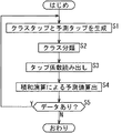
次に、図5のフローチャートを参照して、図2のデコーダ2の処理(復号処理)について説明する。
【0086】
復号部21は、エンコーダ1における符号化方式に対応する復号方式にしたがって、符号化データを復号し、その結果得られる第1復号データを、符号化部22とクラス分類適応処理回路24に供給する。さらに、復号部21は、符号化データを復号する過程において得られる情報を、第1付加情報として、クラス分類適応処理回路24に供給する。符号化部22は、復号部21から供給される符号化データを再符号化し、その結果得られる再符号化データを、復号部23に供給する。復号部23は、復号部21と同様にして、符号化部22からの再符号化データを復号し、その結果得られる第2復号データを、クラス分類適応処理回路24に供給する。さらに、復号部23は、再符号化データを復号する過程において得られる情報を、第2付加情報として、クラス分類適応処理回路24に供給する。
【0087】
クラス分類適応処理回路24(図3)では、ステップS1において、タップ生成部31が、そこに供給される第1復号データを、順次、注目データとし、例えば、その注目データに対して、時間的または空間的に近い位置にある第1復号データ、注目データに対応する第2復号データに対して、時間的または空間的に近い位置にある第2復号データ、注目データの復号過程で得られた第1付加情報、注目データに対応する第2復号データの復号過程で得られた第2付加情報から、注目データについての予測タップを生成し、予測部35に出力する。さらに、ステップS1では、タップ生成部32が、例えば、タップ生成部31と同様にして、注目データについてのクラスタップを生成し、クラス分類部33に出力する。
【0088】
そして、ステップS2に進み、クラス分類部33は、タップ生成部32から供給されるクラスタップに基づいて、クラス分類を行い、その結果得られるクラスコードを、係数メモリ34に供給して、ステップS3に進む。
【0089】
ステップS3では、係数メモリ34は、クラス分類部33から供給されるクラスコードに対応するアドレスから、タップ係数を読み出し、予測部35に供給する。
【0090】
そして、ステップS4に進み、予測部35は、係数メモリ34が出力するタップ係数を取得し、そのタップ係数と、タップ生成部31からの予測タップとを用いて、式(1)に示した積和演算を行い、注目データを高品質にしたデータ(の予測値)を得て、ステップS5に進む。
【0091】
ステップS5では、まだ、注目データとして処理すべき第1復号データがあるかどうかが判定され、あると判定された場合、ステップS1に戻り、次に注目データとすべき第1復号データを、新たに注目データとして、以下、同様の処理を繰り返す。また、ステップS5において、注目データとして処理すべきデータがないと判定された場合、処理を終了する。
【0092】
次に、図6は、図3の係数メモリ34に記憶させるタップ係数の学習処理を行う学習装置の一実施の形態の構成例を示している。
【0093】
学習装置には、図1のエンコーダ1において符号化の対象とされるデータの、例えば、高品質のものが、学習用データとして供給される。この学習用データは、学習の教師となる教師データとして、生徒データ生成部51と正規方程式加算回路60に供給される。
【0094】
生徒データ生成部51は、そこに供給される教師データから、学習の生徒となる生徒データを生成する。
【0095】
即ち、生徒データ生成部51は、符号化部52、媒体特性反映部53、復号部54、符号化部55、および復号部56から構成される。
【0096】
符号化部52は、教師データを、図1のエンコーダ1と同様にして符号化し、その結果得られる符号化データを、媒体特性反映部53に供給する。媒体特性反映部53は、図1の記録媒体3または伝送媒体4を介することによって信号に付加される雑音等を、符号化部52からの符号化データに付加し(反映し)、復号部54に供給する。
【0097】
復号部54、符号化部55、復号部56は、図2に示したデコーダ2の復号部21、符号化部22、復号部23とそれぞれ同様に構成される。従って、復号部54、符号化部55、復号部56では、媒体特性反映部53が出力する符号化データが、図2の復号部21、符号化部22、復号部23それぞれにおける場合と同様に処理され、その結果、復号部54は、第1復号データおよび第1付加情報を、復号部56は、第2復号データおよび第2付加情報を、それぞれ、生徒データとして出力する。この生徒データとしての第1復号データおよび第1付加情報、並びに第2復号データおよび第2付加情報は、タップ生成部57および58に供給される。
【0098】
なお、図2のデコーダ2は、上述したように、復号部23の後段に、符号化部22と復号部23のセットと同様のセットを、1以上設けて構成することができるが、この場合、図6の学習装置の生徒データ生成部51は、デコーダ2と同様に、復号部54の後段に、符号化部55と復号部56のセットと同様のセットを、1以上設けて構成する必要がある。
【0099】
タップ生成部57は、図3のクラス分類適応処理回路24のタップ生成部31と同様に構成され、そこに供給される生徒データとしての第1復号データおよび第1付加情報、並びに第2復号データおよび第2付加情報から、タップ生成部31における場合と同様にして、予測タップを生成し、正規方程式加算回路60に供給する。
【0100】
タップ生成部58は、図3のクラス分類適応処理回路24のタップ生成部32と同様に構成され、そこに供給される生徒データとしての第1復号データおよび第1付加情報、並びに第2復号データおよび第2付加情報から、タップ生成部32における場合と同様にして、クラスタップを生成し、クラス分類部59に供給する。
【0101】
クラス分類部59は、タップ生成部58から供給されるクラスタップに基づいて、図3のクラス分類適応処理回路24のクラス分類部33における場合と同様のクラス分類を行い、その結果得られるクラスコードを、正規方程式加算回路60に供給する。
【0102】
正規方程式加算回路60は、そこに供給される教師データを、順次、注目教師データとして、タップ生成部57から供給される、注目教師データについて生成された予測タップと、注目教師データを対象とした足し込みを、クラス分類部59から供給されるクラスコードが表すクラスごとに行う。
【0103】
即ち、正規方程式加算回路60は、クラス分類部59から供給されるクラスコードに対応するクラスごとに、予測タップ(生徒データ)を用い、式(8)の行列Aにおける各コンポーネントとなっている、生徒データどうしの乗算(xinxim)と、サメーション(Σ)に相当する演算を行う。
【0104】
さらに、正規方程式加算回路60は、やはり、クラス分類部59から供給されるクラスコードに対応するクラスごとに、予測タップ(生徒データ)および注目教師データを用い、式(8)のベクトルvにおける各コンポーネントとなっている、生徒データと注目教師データの乗算(xinyi)と、サメーション(Σ)に相当する演算を行う。
【0105】
正規方程式加算回路60は、以上の足し込みを、そこに供給される教師データすべてを注目教師データとして行い、これにより、各クラスについて、式(8)に示した正規方程式をたてる。
【0106】
タップ係数決定回路61は、正規方程式加算回路60においてクラスごとに生成された正規方程式を解くことにより、クラスごとに、タップ係数を求め、係数メモリ62の、各クラスに対応するアドレスに供給する。
【0107】
なお、学習用データの量や内容等によっては、正規方程式加算回路60において、タップ係数を求めるのに必要な数の正規方程式が得られないクラスが生じる場合があり得るが、タップ係数決定回路61は、そのようなクラスについては、例えば、デフォルトのタップ係数を出力する。
【0108】
係数メモリ62は、タップ係数決定回路61から供給されるクラスごとのタップ係数を記憶する。
【0109】
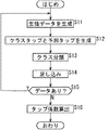
次に、図7のフローチャートを参照して、図6の学習装置の処理(学習処理)について説明する。
【0110】
学習装置には、学習用データが供給され、この学習用データは、教師データとして、生徒データ生成部51と正規方程式加算回路60に供給される。そして、ステップS11において、生徒データ生成部51は、教師データから、生徒データを生成する。
【0111】
即ち、ステップS11では、符号化部52が、教師データを、図1のエンコーダ1と同様に符号化し、その結果得られる符号化データを、媒体特性反映部53を介して、復号部54に供給する。復号部54は、そこに供給される符号化データを復号し、その結果得られる第1復号データを、符号化部55に供給するとともに、生徒データとして、タップ生成部57および58に供給する。また、復号部54は、符号化データを第1復号データに復号する過程において得られる第1付加情報も、生徒データとして、タップ生成部57および58に供給する。
【0112】
さらに、ステップS11では、符号化部55が、復号部54からの第1復号データを再符号化し、その結果得られる再符号化データを、復号部56に供給する。復号部56は、符号化部55からの再符号化データを復号し、その結果得られる第2復号データと、再符号化データを第2復号データに復号する過程において得られる第2付加情報を、生徒データとして、タップ生成部57および58に供給する。
【0113】
その後、正規方程式加算回路60において、そこに供給される教師データが注目教師データとされ、ステップS12に進み、タップ生成部57と58が、そこに供給される生徒データから、注目教師データについて、予測タップとクラスタップを、それぞれ生成する。タップ生成部57で生成された予測タップは、正規方程式加算回路61に供給され、タップ生成部58で生成されたクラスタップは、クラス分類部59に供給される。
【0114】
そして、ステップS13に進み、クラス分類部59が、タップ生成部58からのクラスタップに基づいて、クラス分類を行い、その結果得られるクラスコードを、正規方程式加算回路60に供給して、ステップS14に進む。
【0115】
ステップS14では、正規方程式加算回路60は、クラス分類部59から供給されるクラスコードが表すクラスについて、そこに供給される注目教師データと、タップ生成部57から供給される予測タップを構成する生徒データを対象とした、式(8)の行列Aとベクトルvの、上述したような足し込みを行い、ステップS15に進む。
【0116】
ステップS15では、まだ、注目教師データとして処理すべき教師データがあるかどうかが判定され、あると判定された場合、ステップS11に戻り、例えば、次に供給される教師データを新たに注目教師データとして、以下、同様の処理が繰り返される。
【0117】
また、ステップS15において、注目教師データとして処理すべき教師データがないと判定された場合、即ち、例えば、正規方程式加算回路60において、各クラスについて、正規方程式が得られた場合、ステップS16に進み、タップ係数決定回路61は、各クラスごとに生成された正規方程式を解くことにより、各クラスごとのタップ係数を求め、係数メモリ62の、各クラスに対応するアドレスに供給して記憶させ、処理を終了する。
【0118】
以上のようにして、係数メモリ62に記憶された各クラスごとのタップ係数が、図3の係数メモリ34に記憶されている。
【0119】
従って、図3の係数メモリ34に記憶されたタップ係数は、線形予測演算を行うことにより得られる、学習用データと同様の品質のデータの予測値について、その予測誤差(ここでは、自乗誤差)が、統計的に最小になるように学習を行うことにより求められたものであるから、図3の予測部35が出力する最終的な復号データは、学習用データと同様の品質のものとなる。
【0120】
次に、図8は、図1のデータ伝送システムが、音声信号(音声データ)をCELP(例えば、VSELP(Vector Sum Excited Liner Prediction),PSI-CELP(Pitch Synchronous Innovation CELP),CS-ACELP(Conjugate Structure Algebraic CELP)等の各種のCELPを含む)方式で符号化して伝送する場合の、図1のエンコーダ1の構成例を示している。なお、上述したことから、図1のエンコーダ1が図8に示すように構成される場合は、図2の符号化部22並びに図6の符号化部52および55も、図8に示したのと同様に構成される。
【0121】
符号化の対象となる音声信号(人の発話の他、曲等の信号も含む)は、例えば、アナログの音声信号を、8kHz等のサンプリング周波数でサンプリングすることにより、ディジタルの音声信号にA/D変換し、さらに、所定のビット数で量子化を行って得られたもので、演算器71とLPC(Liner Prediction Coefficient)分析部72に供給される。
【0122】
LPC分析部72は、そこに供給される符号化対象の音声信号を、例えば、160サンプル分の長さのフレームごとにLPC分析し、P次の線形予測係数α1,α2,・・・,αPを求める。そして、LPC分析部72は、このP次の線形予測係数αp(p=1,2,・・・,P)を要素とするベクトルを、音声の特徴ベクトルとして、ベクトル量子化部73に供給する。
【0123】
ベクトル量子化部73は、線形予測係数を要素とするコードベクトルとコードとを対応付けたコードブックを記憶しており、そのコードブックに基づいて、LPC分析部72からの特徴ベクトルαをベクトル量子化し、そのベクトル量子化の結果得られるコード(以下、適宜、Aコード(A_code)という)を、コード決定部83に供給する。
【0124】
さらに、ベクトル量子化部73は、Aコードに対応するコードベクトルα’を構成する要素となっている線形予測係数α1’,α2’,・・・,αP’を、音声合成フィルタ74に供給する。
【0125】
音声合成フィルタ74は、例えば、IIR(Infinite Impulse Response)型のディジタルフィルタで、ベクトル量子化部73からの線形予測係数αp’(p=1,2,・・・,P)をIIRフィルタのタップ係数とするとともに、演算器82から供給される残差信号eを入力信号として、音声合成を行う。
【0126】
即ち、LPC分析部72で行われるLPC分析は、現在時刻nの音声信号(のサンプル値)sn、およびこれに隣接する過去のP個のサンプル値sn-1,sn-2,・・・,sn-Pに、式
sn+α1sn-1+α2sn-2+・・・+αPsn-P=en
・・・(9)
で示す線形1次結合が成立すると仮定し、現在時刻nのサンプル値snの予測値(線形予測値)sn’を、過去のP個の標本値sn-1,sn-2,・・・,sn-Pを用いて、式
sn’=−(α1sn-1+α2sn-2+・・・+αPsn-P)
・・・(10)
によって線形予測したときに、実際のサンプル値snと線形予測値sn’との間の自乗誤差を最小にする線形予測係数αpを求めるものである。
【0127】
ここで、式(9)において、{en}(・・・,en-1,en,en+1,・・・)は、平均値が0で、分散が所定値σ2の互いに無相関な確率変数である。
【0128】
式(9)から、サンプル値snは、式
sn=en−(α1sn-1+α2sn-2+・・・+αPsn-P)
・・・(11)
で表すことができ、これを、Z変換すると、次式が成立する。
【0129】
S=E/(1+α1z-1+α2z-2+・・・+αPz-P)
・・・(12)
但し、式(12)において、SとEは、式(11)におけるsnとenのZ変換を、それぞれ表す。
【0130】
ここで、式(9)および(10)から、enは、式
en=sn−sn’
・・・(13)
で表すことができ、実際のサンプル値snと線形予測値sn’との間の残差信号と呼ばれる。
【0131】
従って、式(12)から、線形予測係数αpをIIRフィルタのタップ係数とするとともに、残差信号enをIIRフィルタの入力信号とすることにより、音声信号snを求めることができる。
【0132】
そこで、音声合成フィルタ74は、上述したように、ベクトル量子化部73からの線形予測係数αp’をタップ係数とするとともに、演算器82から供給される残差信号eを入力信号として、式(12)を演算し、音声信号(合成音信号)ssを求める。
【0133】
なお、音声合成フィルタ74では、LPC分析部72によるLPC分析の結果得られる線形予測係数αpではなく、そのベクトル量子化の結果得られるコードに対応するコードベクトルとしての線形予測係数αp’が用いられるため、音声合成フィルタ74が出力する合成音信号は、LPC分析前の音声信号とは、基本的に同一にはならない。
【0134】
音声合成フィルタ74が出力する合成音信号ssは、演算器71に供給される。演算器71は、音声合成フィルタ74からの合成音信号ssから、元の音声信号sを減算し、その減算値を、自乗誤差演算部75に供給する。自乗誤差演算部75は、演算器71からの減算値の自乗和(第kフレームのサンプル値についての自乗和)を演算し、その結果得られる自乗誤差を、自乗誤差最小判定部76に供給する。
【0135】
自乗誤差最小判定部76は、自乗誤差演算部75が出力する自乗誤差に対応付けて、ラグを表すコードとしてのLコード(L_code)、ゲインを表すコードとしてのGコード(G_code)、および符号語(励起コードブック)を表すコードとしてのIコード(I_code)を記憶しており、自乗誤差演算部75が出力する自乗誤差に対応するLコード、Gコード、およびLコードを出力する。Lコードは、適応コードブック記憶部77に、Gコードは、ゲイン復号器78に、Iコードは、励起コードブック記憶部79に、それぞれ供給される。さらに、Lコード、Gコード、およびIコードは、コード決定部83にも供給される。
【0136】
適応コードブック記憶部77は、例えば7ビットのLコードと、所定の遅延時間(ラグ)とを対応付けた適応コードブックを記憶しており、演算器82から供給される残差信号eを、自乗誤差最小判定部76から供給されるLコードに対応付けられた遅延時間だけ遅延して、演算器80に出力する。
【0137】
ここで、適応コードブック記憶部77は、残差信号eを、Lコードに対応する時間だけ遅延して出力することから、その出力信号は、その遅延時間を周期とする周期信号に近い信号となる。この信号は、線形予測係数を用いた音声合成において、主として、有声音の合成音を生成するための駆動信号となる。
【0138】
ゲイン復号器78は、Gコードと、所定のゲインβおよびγとを対応付けたテーブルを記憶しており、自乗誤差最小判定部76から供給されるGコードに対応付けられたゲインβおよびγを出力する。ゲインβとγは、演算器80と81に、それぞれ供給される。ここで、ゲインβは、長期フィルタ状態出力ゲインと呼ばれるものであり、また、ゲインγは、励起コードブックゲインと呼ばれるものである。
【0139】
励起コードブック記憶部79は、例えば9ビットのIコードと、所定の励起信号とを対応付けた励起コードブックを記憶しており、自乗誤差最小判定部76から供給されるIコードに対応付けられた励起信号を、演算器81に出力する。
【0140】
ここで、励起コードブックに記憶されている励起信号は、例えば、ホワイトノイズ等に近い信号であり、線形予測係数を用いた音声合成において、主として、無声音の合成音を生成するための駆動信号となる。
【0141】
演算器80は、適応コードブック記憶部77の出力信号と、ゲイン復号器78が出力するゲインβとを乗算し、その乗算値lを、演算器82に供給する。演算器81は、励起コードブック記憶部79の出力信号と、ゲイン復号器78が出力するゲインγとを乗算し、その乗算値nを、演算器82に供給する。演算器82は、演算器80からの乗算値lと、演算器81からの乗算値nとを加算し、その加算値を、残差信号eとして、音声合成フィルタ74と適応コードブック記憶部77に供給する。
【0142】
音声合成フィルタ74では、以上のようにして、演算器82から供給される残差信号eが、ベクトル量子化部73から供給される線形予測係数αp’をタップ係数とするIIRフィルタでフィルタリングされ、その結果得られる合成音信号が、演算器71に供給される。そして、演算器71および自乗誤差演算部75において、上述の場合と同様の処理が行われ、その結果得られる自乗誤差が、自乗誤差最小判定部76に供給される。
【0143】
自乗誤差最小判定部76は、自乗誤差演算部75からの自乗誤差が最小(極小)になったかどうかを判定する。そして、自乗誤差最小判定部76は、自乗誤差が最小になっていないと判定した場合、上述のように、その自乗誤差に対応するLコード、Gコード、およびLコードを出力し、以下、同様の処理が繰り返される。
【0144】
一方、自乗誤差最小判定部76は、自乗誤差が最小になったと判定した場合、確定信号を、コード決定部83に出力する。コード決定部83は、ベクトル量子化部73から供給されるAコードをラッチするとともに、自乗誤差最小判定部76から供給されるLコード、Gコード、およびIコードを順次ラッチするようになっており、自乗誤差最小判定部76から確定信号を受信すると、そのときラッチしているAコード、Lコード、Gコード、およびIコードを、チャネルエンコーダ84に供給する。チャネルエンコーダ84は、コード決定部83からのAコード、Lコード、Gコード、およびIコードを多重化し、その多重化結果であるコードデータを、符号化データとして出力する。
【0145】
なお、以下では、説明を簡単にするため、Aコード、Lコード、Gコード、およびIコードは、フレームごとに求められるものとする。但し、例えば、1フレームを、4つのサブフレームに分割し、Lコード、Gコード、およびIコードは、サブフレームごとに求めるようにすること等が可能である。
【0146】
ここで、図8(後述する図9においても同様)では、各変数に、[k]が付され、配列変数とされている。このkは、フレーム数を表すが、明細書中では、その記述は、適宜省略する。
【0147】
次に、図9は、図1のエンコーダ1が図8に示したように構成される場合の、図2の復号部21の構成例を示している。なお、上述したことから、図2の復号部21が図9に示すように構成される場合は、図2の復号部23、並びに図6の復号部54および56も、図9に示したのと同様に構成される。
【0148】
図8のエンコーダ1が出力する符号化データとしてのコードデータは、チャネルデコーダ91で受信される。チャネルデコーダ91は、コードデータから、Lコード、Gコード、Iコード、Aコードを分離し、それぞれを、適応コードブック記憶部92、ゲイン復号器93、励起コードブック記憶部94、フィルタ係数復号器95に供給する。
【0149】
適応コードブック記憶部92、ゲイン復号器93、励起コードブック記憶部94、演算器96乃至98は、図8の適応コードブック記憶部77、ゲイン復号器78、励起コードブック記憶部79、演算器80乃至82とそれぞれ同様に構成されるもので、図8で説明した場合と同様の処理が行われることにより、Lコード、Gコード、およびIコードが、残差信号eに復号される。この残差信号eは、音声合成フィルタ99に対して、入力信号として与えられるとともに、適応コードブック記憶部92に供給される。
【0150】
フィルタ係数復号器95は、図8のベクトル量子化部73が記憶しているのと同一のコードブックを記憶しており、Aコードを、線形予測係数αp’に復号し、音声合成フィルタ99に供給する。
【0151】
音声合成フィルタ99は、図8の音声合成フィルタ74と同様に構成されており、フィルタ係数復号器95からの線形予測係数αp’をタップ係数とするとともに、演算器98から供給される残差信号eを入力信号として、式(12)を演算し、これにより、図8の自乗誤差最小判定部76において自乗誤差が最小と判定されたときの合成音信号を生成する。この合成音信号は、符号化データの復号結果(復号データ)として出力される。
【0152】
一方、付加情報出力部100は、上述のように、符号化データを、復号データとしての合成音信号に復号する過程において得られる情報を取得し、その情報のうちの一部または全部を、付加情報として出力する。
【0153】
即ち、付加情報出力部100には、チャネルデコーダ91が出力するLコード、Gコード、Iコード、およびAコードや、ゲイン復号器93が出力するゲインβおよびγ、フィルタ係数復号器95が出力する線形予測係数αp、演算器96が出力する演算結果l、演算器97が出力する演算結果γ、演算器98が出力する残差信号e等が供給されるようになっており、付加情報出力部100は、これらの情報のうちの一部または全部を、付加情報として出力する。
【0154】
次に、図10は、図1のデータ伝送システムが、静止画の画像データをJPEG方式で符号化して伝送する場合の、図1のエンコーダ1の構成例を示している。なお、図1のエンコーダ1が図10に示すように構成される場合は、図2の符号化部22並びに図6の符号化部52および55も、図10に示したのと同様に構成される。
【0155】
符号化対象の画像データは、ブロック化回路111に入力され、ブロック化回路111は、そこに入力される画像データを、8×8画素の64画素でなるブロックに分割する。ブロック化回路111で得られる各ブロックは、DCT回路112に供給される。DCT回路112は、ブロック化回路111からのブロックに対して、DCT(離散コサイン変換)処理を施し、1個のDC(Direct Current)成分と、水平方向および垂直方向についての63個の周波数成分(AC(Alternating Current)成分)の、合計64個のDCT係数に変換する。各ブロックごとの64個のDCT係数は、DCT回路112から量子化回路113に供給される。
【0156】
量子化回路113は、所定の量子化テーブルにしたがって、DCT回路112からのDCT係数を量子化し、その量子化結果(以下、適宜、量子化DCT係数という)を、量子化に用いた量子化テーブルとともに、エントロピー符号化回路114に供給する。
【0157】
ここで、量子化回路113において用いられる量子化テーブルには、一般に、人間の視覚特性を考慮して、重要性の高い低周波数のDCT係数は細かく量子化し、重要性の低い高周波数のDCT係数は粗く量子化するような量子化ステップが設定されており、これにより、画像の画質の劣化を抑えて、効率の良い圧縮が行われるようになっている。
【0158】
また、JPEG符号化において、どのような量子化テーブルを用いるかは、例えば、ユーザが設定する圧縮率等に基づいて決定される。
【0159】
エントロピー符号化回路114は、量子化回路113からの量子化DCT係数に対して、例えば、ハフマン符号化等のエントロピー符号化処理を施して、量子化回路113からの量子化テーブルを付加し、その結果得られる符号化データを出力する。
【0160】
次に、図11は、図1のエンコーダ1が図10に示したように構成される場合の、図2の復号部21の構成例を示している。なお、図2の復号部21が図11に示すように構成される場合は、図2の復号部23、並びに図6の復号部54および56も、図11に示したのと同様に構成される。
【0161】
符号化データは、エントロピー復号回路121に入力され、エントロピー復号回路121は、符号化データを、エントロピー符号化された量子化DCT係数と、量子化テーブルとに分離する。さらに、エントロピー復号回路121は、エントロピー符号化された量子化DCT係数をエントロピー復号し、その結果得られる量子化DCT係数を、量子化テーブルとともに、逆量子化回路122に供給する。逆量子化回路122は、エントロピー復号回路121からの量子化DCT係数を、同じくエントロピー復号回路121からの量子化テーブルにしたがって逆量子化し、その結果得られるDCT係数を、逆DCT回路123に供給する。逆DCT回路123は、逆量子化回路12からのDCT係数に、逆DCT処理を施し、その結果得られる8×8画素の復号ブロックを、ブロック分解回路124に供給する。ブロック分解回路124は、逆DCT回路123からの復号ブロックのブロック化を解くことで、復号画像データを得て出力する。
【0162】
一方、付加情報出力部125は、上述のように、符号化データを、復号画像データに復号する過程において得られる情報を取得し、その情報のうちの一部または全部を、付加情報として出力する。
【0163】
即ち、付加情報出力部125には、エントロピー復号回路121が出力する量子化テーブルおよび量子化DCT係数や、逆量子化回路122が出力するDCT係数等が供給されるようになっており、付加情報出力部125は、これらの情報のうちの一部または全部を、付加情報として出力する。
【0164】
次に、図12は、図1のデータ伝送システムが、動画の画像データをMPEG2方式で符号化して伝送する場合の、図1のエンコーダ1の構成例を示している。なお、図1のエンコーダ1が図12に示すように構成される場合は、図2の符号化部22並びに図6の符号化部52および55も、図12に示したのと同様に構成される。
【0165】
MPEG符号化の対象である動画を構成するフレーム(またはフィールド)は、順次、動き検出回路131と演算器132に供給される。
【0166】
動き検出回路131は、そこに供給されるフレームについて、マクロブロック単位で、動きベクトルを検出し、エントロピー符号化回路136および動き補償回路140に供給する。
【0167】
演算器132は、そこに供給される画像が、I(Intra)ピクチャであれば、そのままブロック化回路133に供給し、P(Predictive)またはB(Bidirectionally predictive)ピクチャであれば、動き補償回路140から供給される参照画像との差分を演算して、その差分値を、ブロック化回路133に供給する。
【0168】
ブロック化回路133は、演算器132の出力を、8×8画素の画素ブロックにブロック化し、DCT回路134に供給する。DCT回路134は、ブロック化回路133からの画素ブロックをDCT処理し、その結果得られるDCT係数を、量子化回路135に供給する。量子化回路135は、DCT回路133からのブロック単位のDCT係数を所定の量子化テーブルにしたがって量子化し、その結果得られる量子化DCT係数を、用いた量子化テーブルとともに、エントロピー符号化回路136に供給する。エントロピー符号化回路136は、量子化回路135からの量子化DCT係数をエントロピー符号化し、動き検出回路131からの動きベクトルや、量子化回路135からの量子化テーブル、その他の必要な情報(例えば、MPEGストリームの各レイヤのヘッダとなる情報など)を付加して、その結果得られる符号化データを、MPEG符号化結果として出力する。
【0169】
量子化回路135が出力する量子化DCT係数のうち、IピクチャおよびPピクチャは、後で符号化されるPピクチャやBピクチャの参照画像として用いるのにローカルデコードする必要があるため、エントロピー符号化回路136の他、逆量子化回路137にも供給される。また、逆量子化回路137には、量子化回路135で用いられた量子化テーブルも供給される。
【0170】
逆量子化回路137は、量子化回路135からの量子化DCT係数を、同じく量子化回路135からの量子化テーブルにしたがって逆量子化することにより、DCT係数とし、逆DCT回路138に供給する。逆DCT回路138は、逆量子化回路137からのDCT係数を逆DCT処理し、演算器139に出力する。演算器139には、逆DCT回路138の出力の他、動き補償回路140が出力する参照画像も供給されるようになっており、演算器139は、逆DCT回路138の出力が、Pピクチャのものである場合には、その出力と、動き補償回路140の出力とを加算することで、元の画像を復号し、動き補償回路140に供給する。また、演算器139は、逆DCT回路138の出力が、Iピクチャのものである場合には、その出力は、Iピクチャの復号画像となっているので、そのまま、動き補償回路140に供給する。
【0171】
動き補償回路140は、演算器139から供給される、ローカルデコードされた画像に対して、動き検出回路131からの動きベクトルにしたがった動き補償を施し、その動き補償後の画像を、参照画像として、演算器132および99に供給する。
【0172】
次に、図13は、図1のエンコーダ1が図12に示したように構成される場合の、図2の復号部21の構成例を示している。なお、図2の復号部21が図13に示すように構成される場合は、図2の復号部23、並びに図6の復号部54および56も、図13に示したのと同様に構成される。
【0173】
符号化データは、エントロピー復号回路151に供給され、エントロピー復号回路151は、符号化データをエントロピー復号し、量子化DCT係数を得るとともに、その符号化データに含まれる動きベクトル、量子化テーブル、その他の必要な情報を分離する。そして、量子化DCT係数および量子化テーブルは、逆量子化回路152に供給され、動きベクトルは、動き補償回路156に供給される。
【0174】
逆量子化回路152は、エントロピー復号回路151からの量子化DCT係数を、同じくエントロピー復号回路11からの量子化テーブルにしたがって逆量子化することにより、DCT係数とし、逆DCT回路153に供給する。逆DCT回路153は、逆量子化回路152からのDCT係数を逆DCT処理し、演算器154に出力する。演算器154には、逆量子化回路153の出力の他、動き補償回路156が出力する、既に復号されたIピクチャまたはPピクチャを、エントロピー復号回路151からの動きベクトルにしたがって動き補償したものが参照画像として供給されるようになっており、演算器154は、逆DCT回路153の出力が、PまたはBピクチャのものである場合には、その出力と、動き補償回路156の出力とを加算することで、元の画像を復号し、ブロック分解回路155に供給する。また、演算器154は、逆DCT回路153の出力が、Iピクチャのものである場合には、その出力は、Iピクチャの復号画像となっているので、そのまま、ブロック分解回路155に供給する。
【0175】
ブロック分解回路155は、演算器154から画素ブロック単位で供給される復号画像のブロック化を解くことで、復号画像データを得て出力する。
【0176】
また、動き補償回路156は、演算器154が出力する復号画像のうちのIピクチャとPピクチャを受信し、エントロピー復号回路151からの動きベクトルにしたがった動き補償を施す。そして、動き補償回路156は、その動き補償後の画像を、参照画像として、演算器154に供給する。
【0177】
一方、付加情報出力部157は、上述のように、符号化データを、復号画像データに復号する過程において得られる情報を取得し、その情報のうちの一部または全部を、付加情報として出力する。
【0178】
即ち、付加情報出力部157には、エントロピー復号回路151が出力する量子化テーブル、量子化DCT係数、および動きベクトルや、逆量子化回路122が出力するDCT係数が供給されるようになっている。さらに、付加情報出力部157には、エントロピー復号回路151が符号化データをエントロピー復号することにより得られるMPEGストリームの各レイヤに配置された情報(例えば、ピクチャタイプや、ブロックの位置情報、フレームDCTモード/フィールドDCTモードの別など)も供給されるようになっている。付加情報出力部157は、これらの情報のうちの一部または全部を、付加情報として出力する。
【0179】
次に、上述した一連の処理は、ハードウェアにより行うこともできるし、ソフトウェアにより行うこともできる。一連の処理をソフトウェアによって行う場合には、そのソフトウェアを構成するプログラムが、汎用のコンピュータ等にインストールされる。
【0180】
そこで、図14は、上述した一連の処理を実行するプログラムがインストールされるコンピュータの一実施の形態の構成例を示している。
【0181】
プログラムは、コンピュータに内蔵されている記録媒体としてのハードディスク205やROM203に予め記録しておくことができる。
【0182】
あるいはまた、プログラムは、フロッピーディスク、CD-ROM(Compact Disc Read Only Memory),MO(Magneto optical)ディスク,DVD(Digital Versatile Disc)、磁気ディスク、半導体メモリなどのリムーバブル記録媒体211に、一時的あるいは永続的に格納(記録)しておくことができる。このようなリムーバブル記録媒体211は、いわゆるパッケージソフトウエアとして提供することができる。
【0183】
なお、プログラムは、上述したようなリムーバブル記録媒体211からコンピュータにインストールする他、ダウンロードサイトから、ディジタル衛星放送用の人工衛星を介して、コンピュータに無線で転送したり、LAN(Local Area Network)、インターネットといったネットワークを介して、コンピュータに有線で転送し、コンピュータでは、そのようにして転送されてくるプログラムを、通信部208で受信し、内蔵するハードディスク205にインストールすることができる。
【0184】
コンピュータは、CPU(Central Processing Unit)202を内蔵している。CPU202には、バス201を介して、入出力インタフェース210が接続されており、CPU202は、入出力インタフェース210を介して、ユーザによって、キーボードや、マウス、マイク等で構成される入力部207が操作等されることにより指令が入力されると、それにしたがって、ROM(Read Only Memory)203に格納されているプログラムを実行する。あるいは、また、CPU202は、ハードディスク205に格納されているプログラム、衛星若しくはネットワークから転送され、通信部208で受信されてハードディスク205にインストールされたプログラム、またはドライブ209に装着されたリムーバブル記録媒体211から読み出されてハードディスク205にインストールされたプログラムを、RAM(Random Access Memory)204にロードして実行する。これにより、CPU202は、上述したフローチャートにしたがった処理、あるいは上述したブロック図の構成により行われる処理を行う。そして、CPU202は、その処理結果を、必要に応じて、例えば、入出力インタフェース210を介して、LCD(Liquid CryStal Display)やスピーカ等で構成される出力部206から出力、あるいは、通信部208から送信、さらには、ハードディスク205に記録等させる。
【0185】
ここで、本明細書において、コンピュータに各種の処理を行わせるためのプログラムを記述する処理ステップは、必ずしもフローチャートとして記載された順序に沿って時系列に処理する必要はなく、並列的あるいは個別に実行される処理(例えば、並列処理あるいはオブジェクトによる処理)も含むものである。
【0186】
また、プログラムは、1のコンピュータにより処理されるものであっても良いし、複数のコンピュータによって分散処理されるものであっても良い。さらに、プログラムは、遠方のコンピュータに転送されて実行されるものであっても良い。
【0187】
なお、本発明は、特定の符号化/復号方式に限定されることなく適用可能である。即ち、本実施の形態においては、CELP方式、JPEG方式、MPEG2方式について説明したが、本発明は、その他、例えば、M-JPEG(Motion JPEG)方式や、MPEG1,4,MP3(MPEG-1 Audio Layer 3)方式、ATRAC(Adaptive TRansform Acoustic Coding)方式等の種々の符号化/復号方式に適用可能である。
【0188】
また、本実施の形態では、符号化データを、その符号化方式に対応した復号方式によって復号するようにしたが、符号化データの復号は、クラス分類適応処理によって行うことが可能である。クラス分類適応処理による符号化データの復号は、符号化の対象とするデータを教師データとするとともに、そのデータを符号化した符号化データを生徒データとして学習を行うことによって得られるタップ係数を用いることで行うことが可能である。
【0189】
さらに、本実施の形態では、タップ係数を用いた線形1次予測演算によって、高品質のデータの予測値を求めるようにしたが、この予測値は、その他、2次以上の高次の予測演算によって求めることも可能である。
【0190】
また、本実施の形態では、デコーダ2のクラス分類適応処理回路24において、品質を向上させるためのタップ係数を、あらかじめ記憶しておくようにしたが、タップ係数は、符号化データに含めて、デコーダ2に提供するようにすることが可能である。
【0191】
さらに、本実施の形態では、予測タップを、第1復号データおよび第2復号データの他、第1付加情報および第2付加情報から生成するようにしたが、予測タップは、その他、例えば、第1復号データおよび第2復号データだけから生成するようにすること等が可能である。クラスタップについても、同様である。
【0192】
【発明の効果】
本発明のデータ処理装置およびデータ処理方法、並びにプログラムおよび記録媒体によれば、符号化データが復号され、その結果得られる復号データが符号化され、その結果得られる再符号化データが復号され、再復号データが出力される。そして、学習を行うことにより求められたタップ係数との所定の予測演算を行う予測タップが、復号データと再復号データとから生成され、タップ係数が取得され、予測タップとタップ係数とを用いて、所定の予測演算を行うことにより、学習において教師として用いられた教師データに対応する予測値が求められる。従って、例えば、品質が十分に改善されたデータを得ることが可能となる。
【図面の簡単な説明】
【図1】本発明を適用したデータ伝送システムの一実施の形態の構成例を示す図である。
【図2】デコーダ2の構成例を示すブロック図である。
【図3】クラス分類適応処理回路24の構成例を示すブロック図である。
【図4】クラス分類部33および59の構成例を示すブロック図である。
【図5】デコーダ2の処理を説明するフローチャートである。
【図6】本発明を適用した学習装置の一実施の形態の構成例を示すブロック図である。
【図7】学習装置の処理を説明するフローチャートである。
【図8】エンコーダ1、符号化部22,52、および55の第1の構成例を示すブロック図である。
【図9】復号部21,23,54、および56の第1の構成例を示すブロック図である。
【図10】エンコーダ1、符号化部22,52、および55の第2の構成例を示すブロック図である。
【図11】復号部21,23,54、および56の第2の構成例を示すブロック図である。
【図12】エンコーダ1、符号化部22,52、および55の第3の構成例を示すブロック図である。
【図13】復号部21,23,54、および56の第3の構成例を示すブロック図である。
【図14】本発明を適用したコンピュータの一実施の形態の構成例を示すブロック図である。
【符号の説明】
1 エンコーダ, 2 デコーダ, 3 記録媒体, 4 伝送媒体, 21復号部, 22 符号化部, 23 復号部, 24 クラス分類適応処理回路, 31,32 タップ生成部, 33 クラス分類部, 34 係数メモリ, 35 予測部, 41A,41B ADRC回路, 41C 合成回路, 42A,42B 演算器, 43C,43D 極性判別回路, 43E 合成回路,44A,44B 遅延回路, 44C,44D 演算器, 51 生徒データ生成部, 52 符号化部, 53 媒体特性反映部, 54 復号部, 55符号化部, 56 復号部, 57,58 タップ生成部, 59 クラス分類部, 60 正規方程式加算回路, 61 タップ決定回路, 62 係数メモリ, 71 演算器, 72 LPC分析部, 73 ベクトル量子化部, 74 音声合成フィルタ, 75 自乗誤差演算部, 76 自乗誤差最小判定部, 77 適応コードブック記憶部, 78 ゲイン復号器, 79 励起コードブック記憶部, 80乃至82 演算器, 83 コード決定部, 84 チャネルエンコーダ, 91 チャンネルデコーダ, 92 適応コードブック記憶部, 93 ゲイン復号器, 94 励起コードブック記憶部, 95 フィルタ係数復号器, 96乃至98 演算器, 99 音声合成フィルタ, 100 付加情報出力部, 111 ブロック化回路, 112 DCT回路, 113 量子化回路, 114 エントロピー符号化部, 121 エントロピー復号回路, 122 逆量子化回路, 123 逆DCT回路, 124 ブロック分解回路, 125 付加情報出力部, 131 動き検出回路, 132 演算器, 133 ブロック化回路, 134 DCT回路, 135 量子化回路, 136 エントロピー符号化回路, 137 逆量子化回路, 138 逆DCT回路, 139 演算器, 140 動き補償回路, 151 エントロピー復号回路, 152 逆量子化回路, 153 逆DCT回路, 154 演算器, 155 ブロック分解回路, 156 動き補償回路, 157 付加情報出力部, 201 バス, 202 CPU, 203 ROM, 204 RAM, 205 ハードディスク, 206 出力部, 207 入力部, 208 通信部, 209 ドライブ, 210 入出力インタフェース,211 リムーバブル記録媒体[0001]
BACKGROUND OF THE INVENTION
The present invention relates to a data processing device, a data processing method, a program, and a recording medium, and in particular, a data processing device and a data processing method capable of decoding, for example, an image with good image quality, sound with good sound quality, and the like. And a program and a recording medium.
[0002]
[Prior art]
The applicant of the present application has previously proposed class classification adaptive processing as a method for improving the image quality and the sound quality of sound.
[0003]
Class classification adaptive processing consists of class classification processing and adaptive processing. Data is classified into classes based on their properties by class classification processing, and adaptive processing is performed for each class. It is of the technique like.
[0004]
That is, for example, if the target is an image, the adaptive processing obtains a predicted value of the pixel value of the high-quality image by, for example, linear combination of the pixel value of the low-quality image and a predetermined tap coefficient. Thus, the low-quality image is converted into a high-quality image.
[0005]
Specifically, for example, a certain high-quality image is used as teacher data, and the high-quality image is encoded by, for example, the JPEG (Joint Photographic Experts Group) method or the MPEG (Moving Picture Experts Group) method. Furthermore, the decoded image having a reduced image quality obtained by decoding the encoded data is used as the student data, and the predicted value E [y] of the high-quality pixel value y that is the teacher data is set to the low value that is the student data. Some of the image quality pixel values x1, X2, ... and a predetermined tap coefficient w1, W2Consider a linear primary combination model defined by the linear combination of. In this case, the predicted value E [y] can be expressed by the following equation.
[0006]
E [y] = w1x1+ W2x2+ ...
... (1)
[0007]
To generalize equation (1), tap coefficient wjA matrix W consisting ofijAnd a predicted value E [yj] Is a matrix Y ′ consisting of
[Expression 1]
[0008]
XW = Y ’
... (2)
Here, the component x of the matrix XijIs a set of i-th student data (i-th teacher data yiThe j-th student data in the set of student data used for the prediction ofjRepresents a tap coefficient by which the product of the jth student data in the student data set is calculated. YiRepresents the i-th teacher data, and thus E [yi] Represents the predicted value of the i-th teacher data. Note that y on the left side of Equation (1) is the component y of the matrix Y.iThe suffix i is omitted, and x on the right side of Equation (1)1, X2,... Are also components x of matrix XijThe suffix i is omitted.
[0009]
Consider that the least square method is applied to the observation equation (2) to obtain a predicted value E [y] close to the pixel value y with good image quality. In this case, a matrix Y composed of a set of pixel values y serving as teacher data and a matrix E composed of a set of residuals e of predicted values E [y] for the pixel values y are
[Expression 2]
[0010]
XW = Y + E
... (3)
[0011]
In this case, the tap coefficient w for obtaining the predicted value E [y] close to the original pixel value y.jIs the square error
[Equation 3]
[0012]
Therefore, the above square error is converted to the tap coefficient w.jWhen the product differentiated by 0 is 0, that is, the tap coefficient w satisfying the following equation:jIs the optimum value for obtaining the predicted value E [y] close to the pixel value y.
[0013]
[Expression 4]
[0014]
Therefore, first, the equation (3) is changed to the tap coefficient wjIs differentiated by the following equation.
[0015]
[Equation 5]
[0016]
From equations (4) and (5), equation (6) is obtained.
[Formula 6]
[0017]
Furthermore, the student data x in the residual equation of equation (3)ij, Tap coefficient wj, Teacher data yiAnd residual eiConsidering this relationship, the following normal equation can be obtained from the equation (6).
[0018]
[Expression 7]
[0019]
In addition, the normal equation shown in Expression (7) has a matrix (covariance matrix) A and a vector v,
[Equation 8]
AW = v
... (8)
Can be expressed as
[0020]
Each normal equation in equation (7) is the student data xijAnd teacher data yiBy preparing a certain number of sets, a tap coefficient w to be obtainedjTherefore, by solving equation (8) with respect to vector W (however, to solve equation (8), matrix A in equation (8) is regular). Tap coefficient that minimizes statistical prediction error (here, tap coefficient that minimizes square error) wjCan be requested. In solving the equation (8), for example, a sweeping method (Gauss-Jordan elimination method) or the like can be used.
[0021]
As described above, the tap coefficient w that minimizes the statistical prediction errorjAnd tap coefficient wjThe adaptive process is to obtain the predicted value E [y] close to the high-quality pixel value y using the equation (1).
[0022]
For example, an image having the same image quality as the image to be encoded is used as teacher data, and the teacher data is used as student data.Encode and furtherWhen a decoded image obtained by decoding is used, a tap coefficient is obtained that statistically minimizes the prediction error when decoding the encoded image data into the original image data. Become.
[0023]
In addition, for example, an image having a higher resolution than the image to be encoded is used as the teacher data, and the resolution of the teacher data is deteriorated to the same image quality as the image to be encoded as the student data, which is encoded and decoded When using the decoded image obtained by doing so, the tap coefficient is obtained that statistically minimizes the prediction error when decoding the encoded image data into high-resolution image data become.
[0024]
Therefore, in this case, according to the adaptive processing, it is possible to obtain a tap coefficient that can arbitrarily adjust the image quality of the decoded image by changing the image that becomes the teacher data or the student data.
[0025]
Note that the adaptive processing uses a tap coefficient with which the prediction error is statistically minimized by learning, and a high-frequency component that is not included in the image to be encoded by using such a tap coefficient. Is significantly different from simple filtering by a filter in that it may be reproduced.
[0026]
[Problems to be solved by the invention]
From the above, when the class classification adaptive process is performed on the decoded image obtained by decoding the encoded data, a decoded image with improved image quality can be obtained.
[0027]
However, when the image quality of the decoded image obtained by decoding the encoded data is greatly deteriorated due to, for example, the state of the transmission path for transmitting the encoded data or the compression rate at the time of encoding the image data Even if the classification adaptation process is performed using only the decoded image, it may be difficult to sufficiently improve the image quality.
[0028]
The present invention has been made in view of such a situation, and makes it possible to obtain data with sufficiently improved quality.
[0029]
[Means for Solving the Problems]
The present inventionofThe data processing apparatus includes: a decoding unit that decodes encoded data and outputs decoded data; a re-encoding unit that encodes decoded data and outputs re-encoded data;Re-decoding means for decoding the re-encoded data and outputting the re-decoded data;A prediction tap for performing a predetermined prediction calculation with the tap coefficient obtained by learning is re-determined with decoded data.Decrypted dataA prediction tap generation means for generating fromTap coefficient acquisition means for acquiring a tap coefficient;And a prediction unit that obtains a prediction value corresponding to teacher data used as a teacher in learning by performing a predetermined prediction calculation using a prediction tap and a tap coefficient.
[0030]
The present inventionofA data processing method includes: a decoding step for decoding encoded data and outputting decoded data; a re-encoding step for encoding decoded data and outputting re-encoded data;A re-decoding step of decoding the re-encoded data and outputting the re-decoded data;A prediction tap for performing a predetermined prediction calculation with the tap coefficient obtained by learning is re-determined with decoded data.Decrypted dataA prediction tap generation step generated fromA tap coefficient obtaining step for obtaining a tap coefficient;A prediction step of obtaining a prediction value corresponding to teacher data used as a teacher in learning by performing a predetermined prediction calculation using the prediction tap and the tap coefficient.
[0031]
The present inventionofThe programObtained by encoding data into a computerA decoding step for decoding the encoded data and outputting the decoded data; a re-encoding step for encoding the decoded data and outputting the re-encoded data;A re-decoding step of decoding the re-encoded data and outputting the re-decoded data;A prediction tap for performing a predetermined prediction calculation with the tap coefficient obtained by learning is re-determined with decoded data.Decrypted dataA prediction tap generation step generated fromA tap coefficient obtaining step for obtaining a tap coefficient;A prediction step for obtaining a prediction value corresponding to the teacher data used as the teacher in learning by performing a predetermined prediction calculation using the prediction tap and the tap coefficient.Execute the process includingIt is characterized by that.
[0032]
The present inventionofThe recording medium isObtained by encoding data into a computerA decoding step for decoding the encoded data and outputting the decoded data; a re-encoding step for encoding the decoded data and outputting the re-encoded data;A re-decoding step of decoding the re-encoded data and outputting the re-decoded data;A prediction tap for performing a predetermined prediction calculation with the tap coefficient obtained by learning is re-determined with decoded data.Decrypted dataA prediction tap generation step generated fromA tap coefficient obtaining step for obtaining a tap coefficient;A prediction step for obtaining a prediction value corresponding to the teacher data used as the teacher in learning by performing a predetermined prediction calculation using the prediction tap and the tap coefficient.To execute the process includingThe program is recorded.
[0041]
The present inventionofIn the data processing apparatus, the data processing method, the program, and the recording medium, the encoded data is decoded, and the decoded data obtained as a result is encoded., Resulting inThe re-encoded data isDecryptionIsThe re-decoded data is output.And the prediction tap which performs the predetermined prediction calculation with the tap coefficient calculated | required by performing learning is decoded data.WhenReDecrypted dataAnd generated fromTap coefficient is obtained,By performing a predetermined prediction calculation using the prediction tap and the tap coefficient, a prediction value corresponding to the teacher data used as a teacher in learning is obtained.
[0044]
DETAILED DESCRIPTION OF THE INVENTION
FIG. 1 shows a configuration example of an embodiment of a data transmission system to which the present invention is applied.
[0045]
Data to be transmitted is supplied to the encoder 1, and the encoder 1 encodes the data supplied thereto according to, for example, a predetermined encoding method to obtain encoded data. The encoded data is recorded on a recording medium 3 such as a semiconductor memory, a magneto-optical disk, a magnetic disk, an optical disk, a magnetic tape, or a phase change disk, or, for example, terrestrial, satellite, CATV ( Cable Television) is transmitted via a transmission medium 4 such as a network, the Internet, or a public line.
[0046]
The decoder 2 receives and decodes the encoded data provided via the recording medium 3 or the transmission medium 4 and outputs decoded data obtained as a result. When the decoded data is, for example, image data, the image data is supplied to and displayed on a display (not shown), for example. When the encoded data is, for example, audio data, the audio data is supplied to, for example, a speaker (not shown) and output.
[0047]
Next, FIG. 2 shows a configuration example of the decoder 2 of FIG.
[0048]
The encoded data is supplied to the
[0049]
The
[0050]
For example, the
[0051]
Here, hereinafter, the decoded data output from the
[0052]
The class classification
[0053]
Accordingly, the class classification
[0054]
In addition, one or more sets similar to the set of the
[0055]
Next, FIG. 3 shows a configuration example of the class classification
[0056]
The first decoded data, the first additional information, the second decoded data, and the second additional information are supplied to the
[0057]
The
[0058]
The
[0059]
Here, in order to simplify the description, the same class tap and prediction tap are configured. However, the class tap and the prediction tap have different configurations, that is, the first decoded data, the first tap, and the like. Different data can be extracted and generated from the 1 additional information, the second decoded data, and the second additional information.
[0060]
The
[0061]
The
[0062]
The
[0063]
Next, FIG. 4 shows a configuration example of the
[0064]
For example, as shown in FIG. 4A, the
[0065]
In this case,
[0066]
Here, in the K-bit ADRC processing, for example, the maximum value MAX and the minimum value MIN of the information constituting the class tap are detected, and DR = MAX−MIN is set as the local dynamic range of the set, and this dynamic range DR Based on, the information constituting the class tap is requantized to K bits. That is, the minimum value MIN is subtracted from each piece of information constituting the class tap, and the subtracted value is DR / 2.KDivide by (quantize). Then, a bit string in which the K bit values of each piece of information constituting the class tap obtained in the above manner are arranged in a predetermined order is output as an ADRC code.
[0067]
The combining circuit 41C combines the ADRC code of the decoded data output from the
[0068]
Here, as will be described later, the additional information constituting the class tap is not limited to one type. However, when there are a plurality of types of additional information, the
[0069]
Next, for example, as shown in FIG. 4B, the
[0070]
That is, in this case, the
[0071]
Here, the second decoded data corresponding to the first decoded data is obtained as second decoded data that is the same as the decoded pixel obtained as the first decoded data, for example, when the decoded data is an image. Means the decoded pixel. That is, the decoded pixels as the first decoded data and the second decoded data at the position (x, y) in a certain frame f are expressed as p1 (f, x, y) and p2 (f, x, y), respectively. Then, the second decoded data corresponding to the first decoded data p1 (f, x, y) means p2 (f, x, y).
[0072]
The second additional information corresponding to the first additional information is, for example, audio data obtained by decoding the decoded data by a CELP (Code Excited Liner Prediction coding) method, which will be described later, and the additional information is decoded. In the case of the linear prediction coefficient obtained in the process, it means the linear prediction coefficient obtained as the second additional information having the same order as the linear prediction coefficient obtained as the first additional information. That is, the p-th order linear prediction coefficients used for decoding the speech as the first decoded data and the second decoded data in a certain frame (or subframe) f are α1 (f, p) and α2 (f, Assuming that p), the second additional information corresponding to the first additional information α1 (f, p) means α2 (f, p). Further, for example, when the decoded data is image data decoded by a JPEG method to be described later, and the additional information is a DCT coefficient obtained in the decoding process, the second corresponding to the first additional information. The additional information means a DCT coefficient obtained as second additional information having the same spatial frequency component as the DCT coefficient obtained as first additional information. That is, the first additional information and the DCT coefficient as the second additional information at a position (x, y) in a certain 8 × 8 block b of a certain frame f are respectively expressed as d1 (f, b, x, y) and If d2 (f, b, x, y) is expressed, the second additional information corresponding to the first additional information d1 (f, b, x, y) is d2 (f, b, x, y). Means.
[0073]
Thereafter, the same processing as in FIG. 4A is performed on the difference value between the first decoded data and the second decoded data, and the difference value between the first additional information and the second additional information, and the class code is obtained. It is done.
[0074]
Furthermore, the
[0075]
Also in this case, as in the case of FIG. 4B, the
[0076]
The difference value between the first decoded data and the second decoded data is supplied from the
[0077]
The difference value between the first additional information and the second additional information is supplied from the
[0078]
The synthesizing
[0079]
Further, as shown in FIG. 4D, the
[0080]
In this case, the
[0081]
On the other hand, the
[0082]
Hereinafter, in the
[0083]
In addition, the
[0084]
Furthermore, the
[0085]
Next, processing (decoding processing) of the decoder 2 in FIG. 2 will be described with reference to the flowchart in FIG.
[0086]
The
[0087]
In the class classification adaptive processing circuit 24 (FIG. 3), in step S1, the
[0088]
In step S2, the
[0089]
In step S <b> 3, the
[0090]
Then, the process proceeds to step S4, where the
[0091]
In step S5, it is determined whether there is still the first decoded data to be processed as the attention data. If it is determined that there is, the process returns to step S1, and the first decoded data to be the next attention data is newly set. Hereinafter, the same processing is repeated as the attention data. If it is determined in step S5 that there is no data to be processed as attention data, the process ends.
[0092]
Next, FIG. 6 shows a configuration example of an embodiment of a learning device that performs learning processing of tap coefficients to be stored in the
[0093]
For example, high-quality data to be encoded by the encoder 1 shown in FIG. 1 is supplied to the learning device as learning data. This learning data is supplied to the student data generation unit 51 and the normal
[0094]
The student data generation unit 51 generates student data to be learning students from the teacher data supplied thereto.
[0095]
That is, the student data generation unit 51 includes an
[0096]
The
[0097]
The
[0098]
2 can be configured by providing one or more sets similar to the set of the
[0099]
The
[0100]
The
[0101]
The
[0102]
The normal
[0103]
That is, the normal
[0104]
Further, the normal
[0105]
The normal
[0106]
The tap
[0107]
Depending on the amount and content of the learning data, the normal
[0108]
The
[0109]
Next, processing (learning processing) of the learning device in FIG. 6 will be described with reference to the flowchart in FIG.
[0110]
Learning data is supplied to the learning device, and this learning data is supplied to the student data generation unit 51 and the normal
[0111]
That is, in step S11, the
[0112]
Further, in step S <b> 11, the
[0113]
Thereafter, in the normal
[0114]
Then, the process proceeds to step S13, where the
[0115]
In step S <b> 14, the normal
[0116]
In step S15, it is determined whether there is still teacher data to be processed as attention teacher data. If it is determined that there is teacher data, the process returns to step S11. Thereafter, the same processing is repeated.
[0117]
If it is determined in step S15 that there is no teacher data to be processed as attention teacher data, that is, for example, if a normal equation is obtained for each class in the normal
[0118]
As described above, the tap coefficient for each class stored in the
[0119]
Therefore, the tap coefficient stored in the
[0120]
Next, FIG. 8 shows a case where the data transmission system of FIG. 1 shows a configuration example of the encoder 1 in FIG. 1 in the case of encoding and transmitting in accordance with a system including various CELP (such as Structure Algebraic CELP). From the above, when the encoder 1 in FIG. 1 is configured as shown in FIG. 8, the
[0121]
For example, an audio signal to be encoded (including a human utterance and a signal such as a song) is obtained by sampling an analog audio signal at a sampling frequency such as 8 kHz, thereby converting the A / D into a digital audio signal. This is obtained by performing D conversion and further performing quantization with a predetermined number of bits, and is supplied to an
[0122]
The
[0123]
The vector quantization unit 73 stores a code book in which a code vector having a linear prediction coefficient as an element and a code are associated with each other, and based on the code book, the feature vector α from the
[0124]
Further, the vector quantization unit 73 performs linear prediction coefficient α that is an element constituting the code vector α ′ corresponding to the A code.1′, Α2', ..., αP′ Is supplied to the
[0125]
The
[0126]
That is, the LPC analysis performed by the
sn+ Α1sn-1+ Α2sn-2+ ... + αPsnP= En
... (9)
Assuming that the linear linear combination indicated by is established, the sample value s at the current time nnPredicted value (linear predicted value) sn′ Represents the past P sample values sn-1, Sn-2, ..., snPUsing the formula
sn′ = − (Α1sn-1+ Α2sn-2+ ... + αPsnP)
(10)
The actual sample value s when linearly predicted bynAnd linear prediction value snLinear prediction coefficient α that minimizes the square error betweenpIs what you want.
[0127]
Here, in equation (9), {en} (..., en-1, En, En + 1, ...) has an average value of 0 and a variance of a predetermined value σ2Are uncorrelated random variables.
[0128]
From equation (9), the sample value snIs the formula
sn= En-(Α1sn-1+ Α2sn-2+ ... + αPsnP)
(11)
When this is Z-converted, the following equation is established.
[0129]
S = E / (1 + α1z-1+ Α2z-2+ ... + αPz-P)
(12)
However, in Formula (12), S and E are s in Formula (11).nAnd enRepresents the Z transformation of.
[0130]
Here, from equations (9) and (10), enIs the formula
en= Sn-Sn’
(13)
The actual sample value s can be expressed asnAnd linear prediction value snIt is called a residual signal between '.
[0131]
Therefore, from equation (12), the linear prediction coefficient αpIs the tap coefficient of the IIR filter and the residual signal enAs an input signal of the IIR filter,nCan be requested.
[0132]
Therefore, the
[0133]
In the
[0134]
The synthesized sound signal ss output from the
[0135]
The square error
[0136]
The adaptive
[0137]
Here, since the adaptive
[0138]
The
[0139]
The excitation code
[0140]
Here, the excitation signal stored in the excitation codebook is, for example, a signal close to white noise or the like, and in speech synthesis using a linear prediction coefficient, mainly a drive signal for generating unvoiced synthesized sound and Become.
[0141]
The
[0142]
In the
[0143]
The square error
[0144]
On the other hand, when the square error
[0145]
Hereinafter, in order to simplify the description, it is assumed that the A code, the L code, the G code, and the I code are obtained for each frame. However, for example, one frame can be divided into four subframes, and the L code, G code, and I code can be obtained for each subframe.
[0146]
Here, in FIG. 8 (the same applies to FIG. 9 described later), [k] is added to each variable, which is an array variable. Although k represents the number of frames, the description thereof is omitted as appropriate in the specification.
[0147]
Next, FIG. 9 shows a configuration example of the
[0148]
Code data as encoded data output from the encoder 1 in FIG. 8 is received by the
[0149]
The adaptive
[0150]
The filter coefficient decoder 95 stores the same codebook as the vector quantization unit 73 in FIG. 8 stores, and converts the A code into the linear prediction coefficient α.p′ And supplied to the
[0151]
The
[0152]
On the other hand, as described above, the additional
[0153]
That is, the additional
[0154]
Next, FIG. 10 shows a configuration example of the encoder 1 of FIG. 1 when the data transmission system of FIG. 1 encodes and transmits still image data by the JPEG method. When the encoder 1 in FIG. 1 is configured as shown in FIG. 10, the
[0155]
The image data to be encoded is input to the
[0156]
The
[0157]
Here, in the quantization table used in the
[0158]
Also, what kind of quantization table is used in JPEG encoding is determined based on, for example, the compression rate set by the user.
[0159]
The
[0160]
Next, FIG. 11 shows a configuration example of the
[0161]
The encoded data is input to the
[0162]
On the other hand, as described above, the additional
[0163]
That is, the additional
[0164]
Next, FIG. 12 shows a configuration example of the encoder 1 in FIG. 1 when the data transmission system in FIG. 1 encodes and transmits moving image data by the MPEG2 system. When the encoder 1 in FIG. 1 is configured as shown in FIG. 12, the
[0165]
Frames (or fields) constituting a moving image that is a target of MPEG encoding are sequentially supplied to the
[0166]
The
[0167]
If the image supplied thereto is an I (Intra) picture, the
[0168]
The blocking
[0169]
Of the quantized DCT coefficients output from the
[0170]
The
[0171]
The
[0172]
Next, FIG. 13 illustrates a configuration example of the
[0173]
The encoded data is supplied to an
[0174]
The
[0175]
The
[0176]
Also, the
[0177]
On the other hand, as described above, the additional
[0178]
That is, the additional
[0179]
Next, the series of processes described above can be performed by hardware or software. When a series of processing is performed by software, a program constituting the software is installed in a general-purpose computer or the like.
[0180]
Accordingly, FIG. 14 shows a configuration example of an embodiment of a computer in which a program for executing the above-described series of processing is installed.
[0181]
The program can be recorded in advance in a
[0182]
Alternatively, the program is temporarily or temporarily stored on a
[0183]
The program is installed on the computer from the
[0184]
The computer includes a CPU (Central Processing Unit) 202. An input /
[0185]
Here, in the present specification, the processing steps for describing a program for causing the computer to perform various processes do not necessarily have to be processed in time series in the order described in the flowcharts, but in parallel or individually. This includes processing to be executed (for example, parallel processing or processing by an object).
[0186]
Further, the program may be processed by one computer or may be distributedly processed by a plurality of computers. Furthermore, the program may be transferred to a remote computer and executed.
[0187]
The present invention is applicable without being limited to a specific encoding / decoding method. That is, in the present embodiment, the CELP system, the JPEG system, and the MPEG2 system have been described. However, the present invention is not limited to the M-JPEG (Motion JPEG) system, MPEG1, 4, MP3 (MPEG-1 Audio, etc.). The present invention is applicable to various encoding / decoding methods such as Layer 3) method and ATRAC (Adaptive TRansform Acoustic Coding) method.
[0188]
In this embodiment, encoded data is decoded by a decoding method corresponding to the encoding method. However, decoding of the encoded data can be performed by class classification adaptive processing. The decoding of the encoded data by the class classification adaptive process uses the data to be encoded as teacher data and uses tap coefficients obtained by learning the encoded data obtained by encoding the data as student data. Can be done.
[0189]
Furthermore, in the present embodiment, a prediction value of high quality data is obtained by linear primary prediction calculation using a tap coefficient. It is also possible to ask for.
[0190]
Further, in the present embodiment, the tap coefficient for improving the quality is stored in advance in the class classification
[0191]
Furthermore, in the present embodiment, the prediction tap is generated from the first additional information and the second additional information in addition to the first decoded data and the second decoded data. It is possible to generate only from the first decoded data and the second decoded data. The same applies to class taps.
[0192]
【The invention's effect】
The present inventionofAccording to the data processing device, the data processing method, the program, and the recording medium, the encoded data is decoded, and the decoded data obtained as a result is encoded., Resulting inThe re-encoded data isDecryptionIsThe re-decoded data is output.And the prediction tap which performs the predetermined prediction calculation with the tap coefficient calculated | required by performing learning is decoded data.WhenReDecrypted dataAnd generated fromTap coefficient is obtained,By performing a predetermined prediction calculation using the prediction tap and the tap coefficient, a prediction value corresponding to the teacher data used as a teacher in learning is obtained. Therefore, for example, data with sufficiently improved quality can be obtained.
[Brief description of the drawings]
FIG. 1 is a diagram showing a configuration example of an embodiment of a data transmission system to which the present invention is applied.
FIG. 2 is a block diagram illustrating a configuration example of a decoder 2;
FIG. 3 is a block diagram illustrating a configuration example of a class classification
FIG. 4 is a block diagram illustrating a configuration example of
FIG. 5 is a flowchart for explaining processing of the decoder 2;
FIG. 6 is a block diagram illustrating a configuration example of an embodiment of a learning device to which the present invention has been applied.
FIG. 7 is a flowchart illustrating processing of the learning device.
8 is a block diagram illustrating a first configuration example of an encoder 1 and
9 is a block diagram illustrating a first configuration example of
10 is a block diagram illustrating a second configuration example of the encoder 1 and the
11 is a block diagram illustrating a second configuration example of the
12 is a block diagram illustrating a third configuration example of the encoder 1 and the
13 is a block diagram illustrating a third configuration example of the
FIG. 14 is a block diagram illustrating a configuration example of an embodiment of a computer to which the present invention has been applied.
[Explanation of symbols]
DESCRIPTION OF SYMBOLS 1 Encoder, 2 Decoder, 3 Recording medium, 4 Transmission medium, 21 Decoding part, 22 Encoding part, 23 Decoding part, 24 Class classification adaptive processing circuit, 31, 32 Tap generation part, 33 Class classification part, 34 Coefficient memory, 35 prediction unit, 41A, 41B ADRC circuit, 41C synthesis circuit, 42A, 42B computing unit, 43C, 43D polarity discrimination circuit, 43E synthesis circuit, 44A, 44B delay circuit, 44C, 44D computing unit, 51 student data generation unit, 52 Coding section, 53 medium characteristic reflection section, 54 decoding section, 55 coding section, 56 decoding section, 57, 58 tap generation section, 59 class classification section, 60 normal equation addition circuit, 61 tap determination circuit, 62 coefficient memory, 71 computing unit, 72 LPC analysis unit, 73 vector quantization unit 74 speech synthesis filter, 75 square error calculation unit, 76 square error minimum determination unit, 77 adaptive codebook storage unit, 78 gain decoder, 79 excitation codebook storage unit, 80 to 82 calculation unit, 83 code determination unit, 84 channels Encoder, 91 channel decoder, 92 adaptive codebook storage unit, 93 gain decoder, 94 excitation codebook storage unit, 95 filter coefficient decoder, 96 to 98 arithmetic unit, 99 speech synthesis filter, 100 additional information output unit, 111 blocks Circuit, 112 DCT circuit, 113 quantization circuit, 114 entropy coding unit, 121 entropy decoding circuit, 122 inverse quantization circuit, 123 inverse DCT circuit, 124 block decomposition circuit, 125 additional information output unit, 131 Motion detection circuit, 132 arithmetic unit, 133 blocking circuit, 134 DCT circuit, 135 quantization circuit, 136 entropy coding circuit, 137 inverse quantization circuit, 138 inverse DCT circuit, 139 arithmetic unit, 140 motion compensation circuit, 151 entropy Decoding circuit, 152 Inverse quantization circuit, 153 Inverse DCT circuit, 154 arithmetic unit, 155 block decomposition circuit, 156 motion compensation circuit, 157 additional information output unit, 201 bus, 202 CPU, 203 ROM, 204 RAM, 205 hard disk, 206 Output unit, 207 input unit, 208 communication unit, 209 drive, 210 input / output interface, 211 removable recording medium
Claims (10)
前記符号化データを復号し、復号データを出力する復号手段と、
前記復号データを符号化し、再符号化データを出力する再符号化手段と、
前記再符号化データを復号し、再復号データを出力する再復号手段と、
学習を行うことにより求められたタップ係数との所定の予測演算を行う予測タップを、前記復号データと、前記再復号データとから生成する予測タップ生成手段と、
前記タップ係数を取得するタップ係数取得手段と、
前記予測タップとタップ係数とを用いて、所定の予測演算を行うことにより、前記学習において教師として用いられた教師データに対応する予測値を求める予測手段と
を備えることを特徴とするデータ処理装置。A data processing device for processing encoded data obtained by encoding data,
Decoding means for decoding the encoded data and outputting the decoded data;
Re-encoding means for encoding the decoded data and outputting re-encoded data;
Re-decoding means for decoding the re-encoded data and outputting the re-decoded data;
A prediction tap generating means for generating a prediction tap for performing a predetermined prediction calculation with the tap coefficient obtained by learning from the decoded data and the re- decoded data ;
Tap coefficient acquisition means for acquiring the tap coefficient;
A data processing apparatus comprising: a prediction unit that obtains a prediction value corresponding to teacher data used as a teacher in the learning by performing a predetermined prediction calculation using the prediction tap and a tap coefficient. .
ことを特徴とする請求項1に記載のデータ処理装置。The data processing apparatus according to claim 1, wherein the prediction unit obtains the prediction value by performing a linear primary prediction calculation using the prediction tap and a tap coefficient.
前記予測タップ生成手段は、前記付加情報からも、前記予測タップを生成する
ことを特徴とする請求項1に記載のデータ処理装置。The decoding means outputs information obtained in the process of decoding the encoded data as additional information,
The data processing apparatus according to claim 1, wherein the prediction tap generation unit generates the prediction tap also from the additional information.
前記予測タップ生成手段は、前記付加情報からも、前記予測タップを生成する
ことを特徴とする請求項3に記載のデータ処理装置。The re-decoding means outputs information obtained in the process of decoding the re-encoded data as additional information,
The data processing apparatus according to claim 3 , wherein the prediction tap generation unit generates the prediction tap also from the additional information.
前記クラスタップに基づいて、クラス分類を行うクラス分類手段と
をさらに備え、
前記タップ係数取得手段は、前記クラス分類手段が出力するクラスに対応する前記タップ係数を取得し、
前記予測手段は、前記クラス分類手段が出力するクラスに対応する前記タップ係数を用いて、前記予測値を求める
ことを特徴とする請求項1に記載のデータ処理装置。Class tap generation means for generating a class tap used for classifying information to classify information from the decoded data and the re- decoded data ;
Class classification means for performing class classification based on the class tap; and
The tap coefficient acquisition means acquires the tap coefficient corresponding to the class output by the class classification means,
The data processing apparatus according to claim 1, wherein the prediction unit obtains the prediction value using the tap coefficient corresponding to the class output by the class classification unit.
前記クラスタップ生成手段は、前記付加情報からも、前記クラスタップを生成する
ことを特徴とする請求項5に記載のデータ処理装置。The decoding means outputs information obtained in the process of decoding the encoded data as additional information,
The data processing apparatus according to claim 5 , wherein the class tap generation unit generates the class tap also from the additional information.
前記クラスタップ生成手段は、前記付加情報からも、前記クラスタップを生成する
ことを特徴とする請求項6に記載のデータ処理装置。The re-decoding means outputs information obtained in the process of decoding the re-encoded data as additional information,
The data processing apparatus according to claim 6 , wherein the class tap generation unit generates the class tap also from the additional information.
前記符号化データを復号し、復号データを出力する復号ステップと、
前記復号データを符号化し、再符号化データを出力する再符号化ステップと、
前記再符号化データを復号し、再復号データを出力する再復号ステップと、
学習を行うことにより求められたタップ係数との所定の予測演算を行う予測タップを、前記復号データと、前記再復号データとから生成する予測タップ生成ステップと、
前記タップ係数を取得するタップ係数取得ステップと、
前記予測タップとタップ係数とを用いて、所定の予測演算を行うことにより、前記学習において教師として用いられた教師データに対応する予測値を求める予測ステップと
を備えることを特徴とするデータ処理方法。A data processing method for processing encoded data obtained by encoding data,
A decoding step of decoding the encoded data and outputting the decoded data;
A re-encoding step of encoding the decoded data and outputting re-encoded data;
A re-decoding step of decoding the re-encoded data and outputting the re-decoded data;
A prediction tap for performing a predetermined prediction calculation with tap coefficients obtained by performing learning, and the decoded data, and the prediction-tap generation step of generating from said re-decoded data,
A tap coefficient obtaining step for obtaining the tap coefficient;
A prediction step of obtaining a prediction value corresponding to teacher data used as a teacher in the learning by performing a predetermined prediction calculation using the prediction tap and a tap coefficient. .
データを符号化して得られる符号化データを復号し、復号データを出力する復号ステップと、
前記復号データを符号化し、再符号化データを出力する再符号化ステップと、
前記再符号化データを復号し、再復号データを出力する再復号ステップと、
学習を行うことにより求められたタップ係数との所定の予測演算を行う予測タップを、前記復号データと、前記再復号データとから生成する予測タップ生成ステップと、
前記タップ係数を取得するタップ係数取得ステップと、
前記予測タップとタップ係数とを用いて、所定の予測演算を行うことにより、前記学習において教師として用いられた教師データに対応する予測値を求める予測ステップと
を含む処理を実行させることを特徴とするプログラム。 On the computer ,
A decoding step of decoding encoded data obtained by encoding data and outputting decoded data;
A re-encoding step of encoding the decoded data and outputting re-encoded data;
A re-decoding step of decoding the re-encoded data and outputting the re-decoded data;
A prediction tap for performing a predetermined prediction calculation with tap coefficients obtained by performing learning, and the decoded data, and the prediction-tap generation step of generating from said re-decoded data,
A tap coefficient obtaining step for obtaining the tap coefficient;
Performing a process including a prediction step of obtaining a prediction value corresponding to teacher data used as a teacher in the learning by performing a predetermined prediction calculation using the prediction tap and the tap coefficient. Program to do.
データを符号化して得られる符号化データを復号し、復号データを出力する復号ステップと、
前記復号データを符号化し、再符号化データを出力する再符号化ステップと、
前記再符号化データを復号し、再復号データを出力する再復号ステップと、
学習を行うことにより求められたタップ係数との所定の予測演算を行う予測タップを、前記復号データと、前記再復号データとから生成する予測タップ生成ステップと、
前記タップ係数を取得するタップ係数取得ステップと、
前記予測タップとタップ係数とを用いて、所定の予測演算を行うことにより、前記学習において教師として用いられた教師データに対応する予測値を求める予測ステップと
を含む処理を実行させるためのプログラムが記録されている
ことを特徴とする記録媒体。 On the computer ,
A decoding step of decoding encoded data obtained by encoding data and outputting decoded data;
A re-encoding step of encoding the decoded data and outputting re-encoded data;
A re-decoding step of decoding the re-encoded data and outputting the re-decoded data;
A prediction tap for performing a predetermined prediction calculation with tap coefficients obtained by performing learning, and the decoded data, and the prediction-tap generation step of generating from said re-decoded data,
A tap coefficient obtaining step for obtaining the tap coefficient;
A program for executing a process including: a prediction step of obtaining a prediction value corresponding to teacher data used as a teacher in the learning by performing a predetermined prediction calculation using the prediction tap and the tap coefficient. A recording medium characterized by being recorded.
Priority Applications (7)
| Application Number | Priority Date | Filing Date | Title |
|---|---|---|---|
| JP2001016869A JP4507046B2 (en) | 2001-01-25 | 2001-01-25 | Data processing apparatus, data processing method, program, and recording medium |
| CNB028005414A CN1269314C (en) | 2001-01-25 | 2002-01-24 | Data processing apparatus |
| KR20027012587A KR100847179B1 (en) | 2001-01-25 | 2002-01-24 | Data processing apparatus |
| EP02716352A EP1355428B1 (en) | 2001-01-25 | 2002-01-24 | Data processing apparatus |
| US10/239,805 US7082220B2 (en) | 2001-01-25 | 2002-01-24 | Data processing apparatus |
| PCT/JP2002/000490 WO2002060069A1 (en) | 2001-01-25 | 2002-01-24 | Data processing apparatus |
| DE2002611854 DE60211854T2 (en) | 2001-01-25 | 2002-01-24 | DEVICE FOR DATA PROCESSING |
Applications Claiming Priority (1)
| Application Number | Priority Date | Filing Date | Title |
|---|---|---|---|
| JP2001016869A JP4507046B2 (en) | 2001-01-25 | 2001-01-25 | Data processing apparatus, data processing method, program, and recording medium |
Publications (3)
| Publication Number | Publication Date |
|---|---|
| JP2002223167A JP2002223167A (en) | 2002-08-09 |
| JP2002223167A5 JP2002223167A5 (en) | 2008-03-06 |
| JP4507046B2 true JP4507046B2 (en) | 2010-07-21 |
Family
ID=18883164
Family Applications (1)
| Application Number | Title | Priority Date | Filing Date |
|---|---|---|---|
| JP2001016869A Expired - Fee Related JP4507046B2 (en) | 2001-01-25 | 2001-01-25 | Data processing apparatus, data processing method, program, and recording medium |
Country Status (6)
| Country | Link |
|---|---|
| EP (1) | EP1355428B1 (en) |
| JP (1) | JP4507046B2 (en) |
| KR (1) | KR100847179B1 (en) |
| CN (1) | CN1269314C (en) |
| DE (1) | DE60211854T2 (en) |
| WO (1) | WO2002060069A1 (en) |
Families Citing this family (9)
| Publication number | Priority date | Publication date | Assignee | Title |
|---|---|---|---|---|
| JP4462823B2 (en) * | 2002-11-20 | 2010-05-12 | ソニー株式会社 | Image signal processing apparatus and processing method, coefficient data generating apparatus and generating method used therefor, and program for executing each method |
| US7756051B2 (en) | 2004-07-02 | 2010-07-13 | Microsoft Corporation | Content distribution using network coding |
| US8140849B2 (en) | 2004-07-02 | 2012-03-20 | Microsoft Corporation | Security for network coding file distribution |
| JP2008178075A (en) | 2006-12-18 | 2008-07-31 | Sony Corp | Display control device, display control method, and program |
| TW200834537A (en) | 2006-12-18 | 2008-08-16 | Sony Corp | Dynamic image signal processing device |
| TWI384437B (en) | 2006-12-18 | 2013-02-01 | Sony Corp | An image signal processing device, an image signal processing method, and a computer program product |
| JP4656452B2 (en) | 2008-05-20 | 2011-03-23 | ソニー株式会社 | Image signal processing device, image signal processing method, prediction coefficient generation device, prediction coefficient generation processing method, and program for causing computer to execute each method |
| JP5326465B2 (en) | 2008-09-26 | 2013-10-30 | 富士通株式会社 | Audio decoding method, apparatus, and program |
| JP5309944B2 (en) * | 2008-12-11 | 2013-10-09 | 富士通株式会社 | Audio decoding apparatus, method, and program |
Citations (6)
| Publication number | Priority date | Publication date | Assignee | Title |
|---|---|---|---|---|
| JPH06152432A (en) * | 1992-11-13 | 1994-05-31 | Sony Corp | High-efficiency encoder and/or decoder |
| JPH08307835A (en) * | 1995-05-10 | 1996-11-22 | Sony Corp | Classification adaptive processing unit and its method |
| JPH08322041A (en) * | 1995-05-25 | 1996-12-03 | Sony Corp | Block distortion eliminator |
| JPH09186608A (en) * | 1995-12-28 | 1997-07-15 | Sony Corp | Device for converting quantization bit number and its device |
| JPH1155630A (en) * | 1997-07-31 | 1999-02-26 | Sony Corp | Image processor and image processing method |
| JP2001008056A (en) * | 1999-06-21 | 2001-01-12 | Sony Corp | Data processor, data processing method and medium |
Family Cites Families (1)
| Publication number | Priority date | Publication date | Assignee | Title |
|---|---|---|---|---|
| JP3946812B2 (en) * | 1997-05-12 | 2007-07-18 | ソニー株式会社 | Audio signal conversion apparatus and audio signal conversion method |
-
2001
- 2001-01-25 JP JP2001016869A patent/JP4507046B2/en not_active Expired - Fee Related
-
2002
- 2002-01-24 KR KR20027012587A patent/KR100847179B1/en not_active IP Right Cessation
- 2002-01-24 CN CNB028005414A patent/CN1269314C/en not_active Expired - Fee Related
- 2002-01-24 DE DE2002611854 patent/DE60211854T2/en not_active Expired - Lifetime
- 2002-01-24 WO PCT/JP2002/000490 patent/WO2002060069A1/en active IP Right Grant
- 2002-01-24 EP EP02716352A patent/EP1355428B1/en not_active Expired - Lifetime
Patent Citations (6)
| Publication number | Priority date | Publication date | Assignee | Title |
|---|---|---|---|---|
| JPH06152432A (en) * | 1992-11-13 | 1994-05-31 | Sony Corp | High-efficiency encoder and/or decoder |
| JPH08307835A (en) * | 1995-05-10 | 1996-11-22 | Sony Corp | Classification adaptive processing unit and its method |
| JPH08322041A (en) * | 1995-05-25 | 1996-12-03 | Sony Corp | Block distortion eliminator |
| JPH09186608A (en) * | 1995-12-28 | 1997-07-15 | Sony Corp | Device for converting quantization bit number and its device |
| JPH1155630A (en) * | 1997-07-31 | 1999-02-26 | Sony Corp | Image processor and image processing method |
| JP2001008056A (en) * | 1999-06-21 | 2001-01-12 | Sony Corp | Data processor, data processing method and medium |
Also Published As
| Publication number | Publication date |
|---|---|
| EP1355428A4 (en) | 2005-09-07 |
| CN1269314C (en) | 2006-08-09 |
| EP1355428B1 (en) | 2006-05-31 |
| DE60211854D1 (en) | 2006-07-06 |
| EP1355428A1 (en) | 2003-10-22 |
| KR100847179B1 (en) | 2008-07-17 |
| CN1457552A (en) | 2003-11-19 |
| WO2002060069A1 (en) | 2002-08-01 |
| DE60211854T2 (en) | 2007-05-24 |
| KR20030062230A (en) | 2003-07-23 |
| JP2002223167A (en) | 2002-08-09 |
Similar Documents
| Publication | Publication Date | Title |
|---|---|---|
| US7082220B2 (en) | Data processing apparatus | |
| JP4507046B2 (en) | Data processing apparatus, data processing method, program, and recording medium | |
| JPH09152896A (en) | Sound path prediction coefficient encoding/decoding circuit, sound path prediction coefficient encoding circuit, sound path prediction coefficient decoding circuit, sound encoding device and sound decoding device | |
| JP2006133423A (en) | Device for and method of transforming vector | |
| JP4857468B2 (en) | Data processing apparatus, data processing method, program, and recording medium | |
| JPH09127995A (en) | Signal decoding method and signal decoder | |
| JP4748113B2 (en) | Learning device, learning method, program, and recording medium | |
| JP2016536859A (en) | Media signal encoding and decoding method and apparatus using the same | |
| JP4000589B2 (en) | Decoding device, decoding method, program, and recording medium | |
| JP4857467B2 (en) | Data processing apparatus, data processing method, program, and recording medium | |
| JP4517448B2 (en) | Data processing apparatus, data processing method, and recording medium | |
| JP4752088B2 (en) | Data processing apparatus, data processing method, and recording medium | |
| JP4218271B2 (en) | Data processing apparatus, data processing method, program, and recording medium | |
| Yang et al. | Multi-stage encoding scheme for multiple audio objects using compressed sensing | |
| JP4438655B2 (en) | Encoding device, decoding device, encoding method, and decoding method | |
| JP4505729B2 (en) | Image processing apparatus, image processing method, program, and recording medium | |
| Werner et al. | An enhanced SBR tool for low-delay applications | |
| JP4538698B2 (en) | Data processing apparatus, data processing method, and recording medium | |
| WO2011087333A2 (en) | Method and apparatus for processing an audio signal | |
| JP4736266B2 (en) | Audio processing device, audio processing method, learning device, learning method, program, and recording medium | |
| JP4517262B2 (en) | Audio processing device, audio processing method, learning device, learning method, and recording medium | |
| JP4538699B2 (en) | Data processing apparatus, data processing method, and recording medium | |
| JP2001346209A (en) | Data processing unit and data processing method, and recording medium | |
| KR20230023560A (en) | Methods of encoding and decoding, encoder and decoder performing the methods | |
| JP3714786B2 (en) | Speech encoding device |
Legal Events
| Date | Code | Title | Description |
|---|---|---|---|
| A521 | Written amendment |
Free format text: JAPANESE INTERMEDIATE CODE: A523 Effective date: 20080121 |
|
| A621 | Written request for application examination |
Free format text: JAPANESE INTERMEDIATE CODE: A621 Effective date: 20080121 |
|
| A131 | Notification of reasons for refusal |
Free format text: JAPANESE INTERMEDIATE CODE: A131 Effective date: 20091203 |
|
| A521 | Written amendment |
Free format text: JAPANESE INTERMEDIATE CODE: A523 Effective date: 20100118 |
|
| TRDD | Decision of grant or rejection written | ||
| A01 | Written decision to grant a patent or to grant a registration (utility model) |
Free format text: JAPANESE INTERMEDIATE CODE: A01 Effective date: 20100408 |
|
| A01 | Written decision to grant a patent or to grant a registration (utility model) |
Free format text: JAPANESE INTERMEDIATE CODE: A01 |
|
| A61 | First payment of annual fees (during grant procedure) |
Free format text: JAPANESE INTERMEDIATE CODE: A61 Effective date: 20100421 |
|
| FPAY | Renewal fee payment (event date is renewal date of database) |
Free format text: PAYMENT UNTIL: 20130514 Year of fee payment: 3 |
|
| FPAY | Renewal fee payment (event date is renewal date of database) |
Free format text: PAYMENT UNTIL: 20130514 Year of fee payment: 3 |
|
| R250 | Receipt of annual fees |
Free format text: JAPANESE INTERMEDIATE CODE: R250 |
|
| R250 | Receipt of annual fees |
Free format text: JAPANESE INTERMEDIATE CODE: R250 |
|
| R250 | Receipt of annual fees |
Free format text: JAPANESE INTERMEDIATE CODE: R250 |
|
| LAPS | Cancellation because of no payment of annual fees |