JP4501548B2 - Computer system and device allocation method - Google Patents
Computer system and device allocation method Download PDFInfo
- Publication number
- JP4501548B2 JP4501548B2 JP2004184406A JP2004184406A JP4501548B2 JP 4501548 B2 JP4501548 B2 JP 4501548B2 JP 2004184406 A JP2004184406 A JP 2004184406A JP 2004184406 A JP2004184406 A JP 2004184406A JP 4501548 B2 JP4501548 B2 JP 4501548B2
- Authority
- JP
- Japan
- Prior art keywords
- storage device
- computer
- request
- host computer
- management
- Prior art date
- Legal status (The legal status is an assumption and is not a legal conclusion. Google has not performed a legal analysis and makes no representation as to the accuracy of the status listed.)
- Expired - Fee Related
Links
Images


Description
本発明は、計算機システム、及び、計算機システムにおける計算機への記憶デバイスの割り当て方法に係り、特に、複数の計算機により共用される記憶装置サブシステムを備えた計算機システムにおいて、計算機に対する記憶デバイスの割り当てを行うための方法に関する。 The present invention relates to a computer system and a method for assigning a storage device to a computer in the computer system, and more particularly to assigning a storage device to a computer in a computer system having a storage subsystem shared by a plurality of computers. On how to do.
近年、企業などで利用される計算機システムで扱われる情報量は、飛躍的に増大しており、これに伴いデータを記憶するディスク装置などの容量も増加の一途をたどっている。例えば、磁気ディスク装置においては、数TB(テラバイト)の容量を持つ装置も珍しくなくなってきている。このようなディスク装置に関して、例えば、特許文献1には、1台の記憶装置サブシステムを複数種類の論理的なディスク装置(以下では、デバイスとも呼ぶ)で構成する技術が開示されている。具体的には、ホストコンピュータからアクセスされるデバイス(論理ディスク)として、RAID(Redundant Arrays of Inexpensive Disks)におけるRAID5とRAID1のように、RAIDレベルの異なるものを混在させ、あるいは、論理ディスクを構成するための実際の磁気ディスク装置(物理ディスク装置)として、アクセス速度の異なるものを混在させたディスクサブシステムが開示されている。ユーザは、各デバイスのアクセス頻度に応じて、デバイスを使い分けることができる。
In recent years, the amount of information handled by computer systems used by companies and the like has increased dramatically, and along with this, the capacity of disk devices for storing data has been steadily increasing. For example, in a magnetic disk device, a device having a capacity of several TB (terabytes) has become rare. With regard to such a disk device, for example,
一方、ホスト計算機とディスク装置などの周辺装置との間のインタフェースとして、ファイバチャネル技術が現れたことにより、複数のホスト計算機、複数の記憶装置を1つのファイバチャネルケーブルで接続して計算機システムを構成することも行われるようになってきた。このような計算機システムでは、それぞれのホスト計算機は、ファイバチャネル上の任意の記憶装置に直接アクセスできる。このため、従来ように、各ホスト計算機がそれぞれに記憶装置を持つ場合に比べ、ホスト計算機間でのデータの共有やネットワーク負荷の低減が期待できる。 On the other hand, with the emergence of Fiber Channel technology as an interface between host computers and peripheral devices such as disk devices, a computer system is configured by connecting multiple host computers and multiple storage devices with a single Fiber Channel cable. It has come to be done. In such a computer system, each host computer can directly access any storage device on the fiber channel. For this reason, as compared with the conventional case where each host computer has a storage device, sharing of data between host computers and reduction of network load can be expected.
上述した従来技術によれば、各ホスト計算機がアクセスできるデバイスの数や種類を飛躍的に増加させることができる。しかし、ホスト計算機がアクセスできるデバイスの数や種類が増加するに伴い、各ホスト計算機でのデバイスの管理が難しくなってくる。1つのホスト計算機から多くのデバイスにアクセスできる利点の一方で、ユーザにとっては、ある業務でどのデバイスを使用すれば良いか選択するといったことが困難となる。特に、ファイバチャネルで接続された計算機システムの場合、あるホスト計算機からそのホスト計算機が本来使用していないデバイスにまでアクセスできることとなる。このため、他のホスト計算機が使用しているデバイスに不正アクセスを起こし、データを破壊してしまうといったことが生じ得る。 According to the above-described prior art, the number and types of devices that can be accessed by each host computer can be dramatically increased. However, as the number and types of devices that can be accessed by the host computer increase, it becomes difficult to manage the devices in each host computer. While it is possible to access many devices from one host computer, it is difficult for the user to select which device should be used in a certain job. In particular, in the case of a computer system connected via Fiber Channel, a certain host computer can access a device that is not originally used by the host computer. For this reason, it is possible to cause unauthorized access to a device used by another host computer and destroy data.
特開平10―333839号公報には、このような問題を解決するため、ファイバチャネルで接続された記憶装置が、特定のホスト計算機からのアクセスだけを許可する方法が開示されている。しかし、記憶装置、デバイスが複数になった場合や、異なる種類のデバイスが混在する場合には、処理が複雑であることには変わりはなく、各ホスト計算機で、それぞれデバイスの種類などを常に意識する必要がある。 Japanese Patent Laid-Open No. 10-333839 discloses a method for allowing a storage device connected by a fiber channel only to access from a specific host computer in order to solve such a problem. However, when there are multiple storage devices and devices, or when different types of devices are mixed, the processing remains the same, and each host computer is always aware of the device type. There is a need to.
本発明の目的は、各ホスト計算機が用途に合ったデバイスを必要な時に必要な分だけ利用できるように、デバイスの設定、デバイスの各ホスト計算機への割り当てを容易に行えるようにすることにある。 An object of the present invention is to make it possible to easily set a device and assign a device to each host computer so that each host computer can use a device suitable for the application as needed. .
本発明における計算機システムは、その好ましい一つの態様において、複数の計算機と、これら複数の計算機に接続する記憶装置サブシステムとを有する。記憶装置サブシステムは、複数の記憶デバイスと複数のインタフェースとを有し、各計算機に接続される。複数の計算機の1つは、記憶装置サブシステム内の記憶デバイスと、各計算機と記憶装置サブシステムの接続関係の情報を保持する管理手段を有する。各計算機は、新たにデバイスが必要なとき、管理手段にその容量や種類を通知する。管理手段は、その通知を受けて、要求に合った記憶デバイスを選択する。そして選択したデバイスが計算機からアクセスできるように、記憶装置サブシステムに対し所定の情報を設定するように指示する。管理手段は、また、デバイス割り当ての要求の有った計算機に所定の情報を返却し、要求の有った計算機では、その情報に基づき計算機の設定を変更し、当該計算機で割り当てられたデバイスが使用できるようにする。 In a preferred embodiment, the computer system according to the present invention includes a plurality of computers and a storage subsystem connected to the plurality of computers. The storage subsystem has a plurality of storage devices and a plurality of interfaces, and is connected to each computer. One of the plurality of computers has a storage device in the storage device subsystem and management means for holding information on the connection relationship between each computer and the storage device subsystem. Each computer notifies the management means of its capacity and type when a new device is required. The management means receives the notification and selects a storage device that meets the request. Then, the storage subsystem is instructed to set predetermined information so that the selected device can be accessed from the computer. The management means also returns predetermined information to the computer that requested the device assignment, and the requested computer changes the setting of the computer based on the information, and the device assigned by the computer is changed. Make it available.
本発明の他の態様において、複数の計算機と複数の記憶装置サブシステムがネットワークを介して接続される。任意の計算機上には、各記憶装置サブシステムが有する記憶デバイスと、各計算機と記憶装置サブシステムの接続関係の情報を保持する管理手段が設けられる。各記憶装置サブシステムは、管理手段から指定された計算機に対してアクセスを許可するための制御手段を有する。各計算機は、新たな記憶デバイスを必要とするとき、管理手段にその容量や種類を通知する。管理手段は、通知に応じて要求に合ったデバイスを選択し、選択したデバイスが新たな記憶デバイスを必要とする計算機からアクセスできるように、記憶装置サブシステムに対し当該計算機からのアクセスを許可するよう指示する。管理手段は、また、デバイス割り当てを要求した計算機に所定の情報を返却する。デバイス割り当てを要求した計算機では、管理手段から返却された情報に基づき、計算機の設定を変更し、その計算機から割り当てられたデバイスが使用できるようにする。 In another aspect of the present invention, a plurality of computers and a plurality of storage device subsystems are connected via a network. On an arbitrary computer, a storage device included in each storage device subsystem and management means for holding information on the connection relationship between each computer and the storage device subsystem are provided. Each storage subsystem has control means for permitting access to the computer designated by the management means. When each computer needs a new storage device, it notifies the management means of its capacity and type. The management means selects a device that meets the request in response to the notification, and permits the storage subsystem to access from the computer so that the selected device can be accessed from the computer that requires the new storage device. Instruct. The management means also returns predetermined information to the computer that requested the device assignment. The computer that requested the device assignment changes the setting of the computer based on the information returned from the management means so that the device assigned from the computer can be used.
本発明によれば、ホスト計算機に対する記憶デバイスの割り当てを必要に応じて動的に行うことができる。 According to the present invention, storage devices can be dynamically allocated to a host computer as necessary.
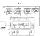
図1は、本発明が適用された計算機システムの一実施形態における構成例を示す簡略なブロック図である。 FIG. 1 is a simplified block diagram showing a configuration example in an embodiment of a computer system to which the present invention is applied.
計算機システムは、複数のホスト計算機、ホスト計算機1a、ホスト計算機1b、…ホスト計算機1n(総称してホスト1と呼ぶ)、ホスト1に接続される記憶装置サブシステム2、管理用ホスト計算機3、ネットワーク4、及び遠隔地に配置される記憶装置である副記憶装置5を有して構成される。
The computer system includes a plurality of host computers, a
ホスト計算機1a、1b、…は、CPU、メモリなどを有する計算機であり、メモリに格納されたオペレーティングシステム、アプリケーションプログラムをCPUが読み出して実行することで、所定の機能を達成する。
The
記憶装置サブシステム2は、複数のディスクユニット21、ディスクコントローラ22、ホスト計算機1と接続する複数のポート23、副記憶装置5と接続するためのインタフェース24、ネットワーク4と接続するネットワークインタフェース25を有している。本実施形態における記憶装置サブシステム2は、複数のディスクユニット21をまとめて1または複数の論理デバイスとしてホスト計算機1に見せかける。もちろん、個々のディスクユニット21を1つの論理デバイスとしてホスト計算機1に見せるようにしても良い。
The
ポート23としては、たとえば、接続されるホスト計算機1が、いわゆるオープンシステムの計算機であればSCSI(Small Computer System Interface)などのインタフェースが用いられる。一方、ホスト計算機1が、いわゆるメインフレームであれば、ESCON(Enterprise System CONnection)などのチャネルインタフェースが用いられる。それぞれのポート23は、同一のインタフェースであっても異なるものが混在していてもかまわない。本実施形態では、全てのポート23にインタフェースとして、SCSIを用いるものとして説明する。
As the
ディスクコントローラ22は、プロセッサ221、キャッシュメモリ222、制御メモリ223を有している。プロセッサ221は、ホスト計算機1からのアクセスやディスクユニット21の制御を行う。プロセッサ221は、特に、記憶装置サブシステム2がホスト計算機1に対してディスクユニット21単体ではなく、ディスクアレイの様に複数のディスクユニットをまとめて1または複数の論理デバイスに見せかけている場合には、その処理や管理などを行う。ディスクコントローラ22は、ネットワークインタフェース25を介して管理用ホスト計算機3との通信を行う。
The
キャッシュメモリ222は、ホスト計算機1からのアクセス処理速度を高めるため、頻繁に読み出されるデータを格納したり、あるいはホスト計算機1からのライトデータを一時的に格納したりする。キャッシュメモリ222の一部を、1または複数の論理的なディスクに見せかけ、磁気ディスクユニットへのアクセスが不要なデバイスとして利用することもできる。
The
制御メモリ223は、プロセッサ221が実行するプログラムを格納し、また、ディスクユニット21や、複数のディスクユニット21を組み合わせて構成される論理デバイスの管理を行うための情報を格納するために使用される。
The
各ホスト計算機1a、1b…には、ボリュームマネージャ11と呼ばれるソフトウェア(プログラム)が配置される。ボリュームマネージャ11は、管理用ホスト計算機3に配置される管理マネージャ31と通信しあって動作する。各ホスト計算機1は、インタフェース(I/F)12を持っており、インタフェース12により記憶装置サブシステム2のポート23と接続される。
Each
次に、記憶装置サブシステム2内の論理デバイスの管理形態について説明する。
Next, the management form of the logical devices in the
前述の通り、記憶装置サブシステム2は、複数のディスクユニット21を1または複数の論理デバイスとして、あるいは、個々のディスクユニット21を1つの論理デバイスとしてホスト計算機1に見せかける。記憶装置サブシステム2は、また、キャッシュメモリ222の一部の領域を1または複数の論理デバイスとしてホスト計算機1に見せる。記憶装置サブシステム2内のディスクユニット21の数と論理デバイスの数に相関関係はない。
As described above, the
図2は、記憶装置サブシステム2が論理デバイスを管理するために使用する情報を保持する論理デバイス管理テーブルの一例を示すテーブル構成図である。
FIG. 2 is a table configuration diagram showing an example of a logical device management table that holds information used by the
論理デバイス管理テーブルは、論理デバイス番号61に対し、サイズ62、構成63、状態64、パス65、ターゲットID66,LUN67の項目の組を保持する。サイズ62には、論理デバイス番号61により特定される論理デバイスの容量を表す情報が設定される。
The logical device management table holds a set of items of
構成63には、当該論理デバイスの構成を示す情報、たとえばディスクユニット21によりRAID(Redundant Arrays of Inexpensive Disks)が構成され、それが論理デバイスに割り当てられている場合、RAID1、RAID5など、RAIDの種別を示す情報が設定される。また、当該論理デバイスとして、キャッシュメモリ222の一部の領域が割り当てられていれば「キャッシュ」、単体のディスクユニットが割り当てられている場合には「単体ディスクユニット」を示す情報が構成63に設定される。
In the
状態64には、当該論理デバイスの状態を示す情報が設定される。状態としては、「オンライン」、「オフライン」、「未実装」、「障害オフライン」が存在する。「オンライン」は、当該論理デバイスが正常に稼動し、ホスト計算機1からのアクセスが可能な状態であることを示す。「オフライン」は、当該論理デバイスは定義され、正常に稼動しているが、ホスト計算機1からのアクセスはできない状態にあることを示す。この状態は、以前ホスト計算機1で使用されていたが、ホスト計算機1でそのデバイスが不要となって使われなくなった場合に相当する。「未実装」は、当該論理デバイスが定義されておらずホストからのアクセスはできない状態にあることを示す。また「障害オフライン」は、当該論理デバイスに障害が発生してホストからのアクセスができないことを示す。
In the
パス65には、当該論理デバイスが複数のポート23のどのポートに接続されているかを表す情報が設定される。各ポート23には、記憶装置サブシステム2内で一意な番号が割り振られており、「パス」欄には論理デバイスが接続されているポート23の番号が記録される。ターゲットID66とLUN67は、論理デバイスを識別するための識別子である。ここでは、これらの識別子として、SCSI上でホスト計算機1からデバイスをアクセスする場合に用いられるSCSI−ID、LUNが用いられる。
In the
1つの論理デバイスを複数のポートに接続し、複数のホスト計算機1から同一の論理デバイスをアクセス可能とすることができる。この場合、論理デバイス管理テーブルには、当該論理デバイスに関する複数のエントリが作成される。例えば、図2に示す論理デバイス管理テーブルでは、論理デバイス番号2番のデバイスはポート番号0、及び1の2つのポート23に接続されている。このため、論理デバイス番号2番の項目が2つ存在している。1つの論理デバイスがこのように複数のポート23からアクセス可能とされる場合、それぞれのパス65に対応するターゲットID、LUNは同一である必要はなく、図2に示されるように異なっていても良い。
One logical device can be connected to a plurality of ports, and the same logical device can be accessed from a plurality of
論理デバイス管理テーブルに保持された情報は、ネットワークインタフェース24を通じて、適当なタイミングで、あるいは記憶装置サブシステム2に障害が発生して構成が変化した、などの際に管理用ホスト計算機3に送られる。このため、管理用ホスト計算機3も、図2に示すテーブルと同様の論理デバイス管理テーブルを保持する。
The information held in the logical device management table is sent to the
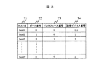
図3は、管理用ホスト計算機3の管理マネージャ31により保持されるホスト管理テーブルの一例を示すテーブル構成図である。
FIG. 3 is a table configuration diagram showing an example of a host management table held by the
ホスト管理テーブルは、管理用ホスト計算機3が各ホスト計算機1に対するデバイスの割り当てを管理するために、ホスト名71、ポート番号72、インタフェース番号73、論理デバイス番号74の組で構成される管理情報を保持する。
The host management table stores management information including a
ポート番号72と論理デバイス番号74は、記憶装置サブシステム2の内部で定義される番号で、記憶装置サブシステム2の各ポート23及び論理デバイスを識別するための情報である。ポート番号72と論理デバイス番号74には、ホスト名71に設定された識別子で識別されるホスト計算機1が接続されるポートのポート番号と、そのホスト計算機に割り当てられている論理デバイスのデバイス番号が設定される。
The
インタフェース番号73は、各ホスト計算機1のインタフェース12を管理するために付けられた番号である。インタフェース番号73は、特に、1つのホスト計算機1が複数のインタフェース12を持つ場合に必要となる。ポート番号72とインタフェース番号73の組は、ホスト計算機1と論理デバイスの接続関係を示すために重要な要素である。例えば、図1に示すホスト計算機1bは、2つのインタフェース12を備え、各インタフェース12は、それぞれ異なるポート23に接続されている。このような場合、一方のインタフェース、あるいは、一方のインタフェースと記憶装置サブシステム2を接続するラインの障害などにより使えなくなっても、他方のインタフェースから論理デバイスへの接続がなされていれば処理を続行でき、信頼性を高めることができる。
The
管理用ホスト計算機3は、ホスト管理テーブルと、記憶装置サブシステム2から送られる論理デバイス管理テーブルを参照して、各ホスト計算機1に論理デバイスを割り当てる。以下、デバイスの割り当ての処理について説明する。
The
図4は、各ホスト計算機1のボリュームマネージャ11により実施される処理の流れを示すフローチャートである。この処理は、ホスト計算機1を使用するユーザ、またはホスト計算機1で稼動するアプリケーションプログラムなどが新規にデバイスを必要とするときに実施される。
FIG. 4 is a flowchart showing the flow of processing performed by the
ステップ1001で、ボリュームマネージャ11は、ユーザ、またはアプリケーションプログラムから必要とされるデバイスの数とデバイスの種類の情報を得る。ユーザ、またはアプリケーションプログラムは、デバイスに関する情報として、その容量、性能条件、信頼性レベルなどの情報を指定する。デバイスの容量とは、先に説明したデバイスのサイズのことである。性能条件としては、例えば、低速ディスクドライブ、高速ディスクドライブ、キャッシュ常駐ディスクドライブといった、デバイスのアクセス速度などの性能に関する情報が指定される。信頼性レベルとしては、例えば、RAID0、RAID1、RAID5、二重パス、リモートミラーなど、デバイスの信頼性に関する情報が指定される。二重パスでは、ホスト計算機1が複数のインタフェースを持つ場合に、それら複数のインタフェースを利用して同一デバイスにアクセスできるよう複数のパスが設けられる。二重パスでは、あるパスが利用できなくなった時でも、他のパスを使ってそのデバイスにアクセスすることが可能となる。リモートミラーは、副記憶装置5に記憶装置サブシステム2内のデバイスのコピーを持たせるものであり、地震、火災などの要因で記憶装置サブシステム2そのものが稼動できなくなった場合にも、副記憶装置5にデータが保持されているため、信頼性を高めることができる。
In
次に、ステップ1002でボリュームマネージャ11は、当該ホスト計算機1のインタフェース12上で使用されていないターゲットID、LUNの組を検索する。
In
ステップ1003でボリュームマネージャ11は、ステップ1001において指定された容量、性能条件、信頼性レベル、及びステップ1002で検索された未使用のターゲットID、LUNの組を管理用ホスト計算機3の管理マネージャ31に送信し、新たなデバイスの割付を要求する。管理マネージャ31は、受け取った情報に基づいて割り当てるべきデバイスを検索し、そのデバイスのアクセスに使用するホストインタフェース番号、ターゲットID、及びLUNを指定する情報を返却する。ここで行われる管理マネージャ31の処理については後述する。
In
ステップ1004でボリュームマネージャ11は、管理マネージャ13からの情報を受け取る。ステップ1005では、管理マネージャ13から受け取った情報をもとに、新しいデバイスを使用できるようにホスト計算機1の設定変更が行われる。
In
いわゆるオープン系のオペレーティングシステムの場合、ホスト計算機1が各デバイスにアクセスするために、デバイスファイルがデバイス毎に用意され、デバイスファイルに対してアクセスが実施される。通常、デバイスファイルは、ホスト計算機1のデバイスコンフィギュレーション処理を行った際に用意され、デバイスコンフィギュレーション処理時に存在しないデバイスについては、デバイスファイルが作成されていない。このため、ステップ1004では、新しく割り当てられたデバイスに関するデバイスファイルが作成される。具体的には、例えば、サンマイクロシステムズ社のSolarisオペレーティングシステムでは、“drvconfig”コマンド、あるいは“drives”コマンドにより、新規デバイスの認識、デバイスファイルの作成が行われ、ホスト計算機1から新たに割り当てられたデバイスに対してアクセスできるようになる。
In the case of a so-called open system, a device file is prepared for each device so that the
最後にステップ1006でボリュームマネージャ11は、割り当てられたデバイスファイル名、ターゲットID、LUNの情報をユーザまたはアプリケーションプログラムに通知して処理を終了する。
Finally, in
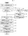
図5は、新しいデバイスの割り当て時に管理用ホスト計算機3の管理マネージャ31による処理の流れを示すフローチャートである。
FIG. 5 is a flowchart showing the flow of processing by the
管理マネージャ31は、ステップ1101でホスト計算機1から送られてきたデバイスサイズ、性能条件、信頼度レベルなどの情報を受け取ると、保持している論理デバイス管理テーブル、及びホスト管理テーブルに設定されている情報を参照し、要求に応じたデバイスが存在するか検索する。ここで検索対象となるデバイスは、論理デバイス管理テーブルの状態64に「オフライン」が設定されているものである(ステップ1102)。管理マネージャ31は、検索の結果、要求に合った「オフライン」状態のデバイスが見つかったかどうか判別する(ステップ1103)。
When the
要求に合った「オフライン」状態のデバイスが見つかった場合、管理マネージャ31は、ホスト計算機1から受け取ったターゲットID、LUNの情報と、論理デバイス管理テーブル及びホスト管理テーブルに設定されている情報に基づいて、当該デバイスをホスト計算機1に接続するために使用するポート番号、ターゲットID、LUNを決定する(ステップ1104)。
When a device in the “offline” state that matches the request is found, the
次に、管理マネージャ31は、ステップ1103で見つけた論理デバイス番号のデバイスを、ステップ1104で決定したポート番号、ターゲットID、LUNでアクセスできるように設定してオンライン状態にするよう記憶装置サブシステム2に指示する。記憶装置サブシステム2は、管理マネージャ31からの指示に従って設定を行い、その結果を管理マネージャ31に返却する(ステップ1105)。
Next, the
管理マネージャ31は、記憶装置サブシステム2から結果を受け取ると(ステップ1106)、要求のあったホスト計算機1のボリュームマネージャ11に対して、インタフェース番号、ターゲットID、LUNを返却する(ステップ1107)。
When the
一方、ステップ1103で「オフライン」状態のデバイスで要求に合ったものが存在しなかった場合、管理マネージャ31は、論理デバイス管理テーブルの状態64が「未実装」の論理デバイス番号が存在するか検索する(ステップ1108)。「未実装」の論理デバイス番号が存在する場合、管理マネージャ31は、記憶装置サブシステム2に対して、ホスト計算機1から要求のあったデバイスサイズ、性能条件、信頼度レベルなどの情報を伝えてデバイスの構築を要求する。記憶装置サブシステム2は、管理マネージャ31から要求に合わせて当該デバイス番号のデバイスを構築し、管理マネージャ31にその結果を返却する(ステップ1109)。管理マネージャ31は、その結果を受け取ると、上述したステップ1104以降の処理を実施する(ステップ1110)。
On the other hand, if there is no device that meets the request in the “offline” state in
図6は、ホスト計算機1で不必要になったデバイスの返却処理においてボリュームマネージャ11が実施する処理の流れを示すフローチャートである。
FIG. 6 is a flowchart showing the flow of processing executed by the
デバイスの返却処理において、ボリュームマネージャ11は、まず、ユーザ、あるいは上位アプリケーションプログラムから不必要になったデバイスの情報、例えば、デバイスファイル名を受け取る(ステップ1201)。ボリュームマネージャ11は、受け取った情報をもとに、返却処理の対象となるデバイスに関連するインタフェース番号、ターゲットID、LUNを取得する(ステップ1202)。
In the device return process, the
次に、ボリュームマネージャ11は、ホスト計算機1でそのデバイスを使わないようにするため、必要に応じてホスト計算機1の設定変更を行う。ここでは、具体的には、デバイスファイルの削除などの処理が行われる(ステップ1203)。続いて、ボリュームマネージャ11は、ステップ1202で取得したインタフェース番号、ターゲットID、LUNを管理マネージャ31に通知し、処理を終了する(ステップ1204)。
Next, the
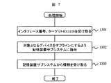
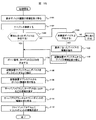
図7は、ホスト計算機1で不必要になったデバイスの返却処理において管理マネージャ31が実施する処理の流れを示すフローチャートである。
FIG. 7 is a flowchart showing the flow of processing performed by the
管理マネージャ31は、ホスト計算機1からインタフェース番号、ターゲットID、LUNを受け取る(ステップ1301)。管理マネージャ31は、受け取ったインタフェース番号、ターゲットID、LUNに基づいて、記憶装置サブシステム2に対し、返却の対象とされているデバイスをオフラインにするよう指示する。この指示に応じて、記憶装置サブシステム2は、指定されたデバイスをオフラインとし、その結果を反映した論理デバイス管理テーブルを管理マネージャ31に返却する(ステップ1302)。記憶装置サブシステム2から、論理デバイス管理テーブルを受け取ると、それを保持して処理を完了する(ステップ1303)。
The
上述した第1の実施形態では、管理用ホスト計算機を設け、そこに管理マネージャを配置しているが、管理マネージャの機能は必ずしも管理用ホスト計算機に存在する必要はない。例えば、ホスト計算機1a、1b、…のいずれかに存在するように構成することも可能である。また、管理マネージャの機能を記憶装置サブシステムに設けることもできる。この場合、各ホスト計算機1a、1b、…は、インタフェースを介して直接記憶装置サブシステムとの間で、要求の送出、情報受け取りを行えばよい。
In the first embodiment described above, the management host computer is provided and the management manager is arranged there, but the function of the management manager does not necessarily have to exist in the management host computer. For example, it may be configured to exist in any of the
図8は、本発明の第2の実施形態における計算機システムの構成を示す簡略なブロック図である。 FIG. 8 is a simplified block diagram showing the configuration of a computer system according to the second embodiment of the present invention.
本実施形態における計算機システムは、複数のホスト計算機1(ホスト計算機1a、ホスト計算機1b、…、ホスト計算機1n)と、複数の記憶装置サブシステム2a、2b、…、2m、管理用ホスト計算機3、ネットワーク4、及びファイバチャネルスイッチ6を有して構成される。
The computer system in this embodiment includes a plurality of host computers 1 (
ホスト計算機1は、第1の実施形態と同じく、ボリュームマネージャ11を有する。ボリュームマネージャ11は、管理用ホスト計算機3におかれた管理マネージャ31と通信しあって動作する。さらに、ホスト計算機1は、インタフェース(I/F)12を有し、インタフェース12によりファイバチャネルスイッチ8と接続される。
The
記憶装置サブシステム2a、2b、…、2mは、それぞれ、第1の実施形態における記憶装置サブシステム2と同様に、ディスクユニット21、ディスクコントローラ22、ポート23、ネットワークと接続するネットワークインタフェース(ネットワークI/F)25を含んで構成される。第1の実施形態と同じくディスクユニット21、ポート23は複数あってもよいが、ここでは説明を簡単にするためディスクユニット、及びポートは、それぞれ1つであるものとして説明する。
The
ファイバチャネルスイッチ8は、複数のポート81を有する。各ポート81には、ホスト計算機1a、1b、…のインタフェース12、及び、記憶装置サブシステム2a、2b、…のポート23のいずれかが接続される。ファイバチャネルスイッチ8は、ネットワークインタフェース82を有しており、ネットワーク4にも接続されている。ファイバチャネルスイッチ8は、ホスト計算機1a、1b、…が、記憶装置サブシステム2a、2b、…を自由にアクセスできるようにするために使用される。この構成では、基本的にすべてのホスト計算機1が、すべての記憶装置サブシステム2にアクセスすることが可能である。
管理用ホスト計算機3は、第1の実施形態と同じく、管理マネージャ31を有する。管理マネージャ31は、各ホスト計算機1a、1b、…のボリュームマネージャ11と通信しあって動作する。
The fiber channel switch 8 has a plurality of
The
図9は、管理用ホスト計算機3が保持する論理デバイス管理テーブルの一例を示すテーブル構成図である。本実施形態における論理デバイス管理テーブルは、第1の実施形態において記憶装置サブシステム2が保持する論理デバイス管理テーブルと同様の情報を管理するために用いられる。以下、主に第1の実施形態における論理デバイス管理テーブルとの相違点について説明する。
FIG. 9 is a table configuration diagram showing an example of a logical device management table held by the
本実施形態において、管理用ホスト計算機3は、全ての記憶装置サブシステム2が有する全てのデバイスに一意な番号をつけて管理する。この管理の目的のため、論理デバイス管理テーブルには、デバイス毎にそのサイズ103、構成104、状態105、LUN106、WWN(World Wide Name)102、及び接続ホスト名107を情報として持つ。
In this embodiment, the
サイズ103、構成104、状態105、LUN106については、第1の実施形態における論理デバイス管理テーブルが保持する情報と同じものである。WWN102は、記憶装置サブシステム2のポート23に設定されている情報で、各ポートを識別するために個々のファイバチャネルインタフェースに固有に割り付けられている情報である。WWN107は、N_PORT_NAMEとも呼ばれる。接続ホスト名107は、当該デバイスに接続が許可されているホスト計算機を識別するためのホスト名である。
The
基本的に、ファイバチャネルスイッチ8に接続された複数のホスト計算機1が任意の記憶装置サブシステム2に自由にアクセスできると、システムの安全上問題となることがある。このようなシステムの安全性に関する問題を解決するために、例えば、特開平10―333839号公報には、ファイバチャネルで接続された記憶装置に対し、特定のホスト計算機からのアクセスだけを許可することを可能とする技術が開示されている。本実施形態でも、システムの安全性を維持するために、記憶装置サブシステム2は、特開平10―333839号公報に開示されているような安全性を維持するための手段を持っているものとする。ただし、これについては、本発明の本質とは直接関係するところではなく、ここでは詳しい説明を省略する。
Basically, if a plurality of
本実施形態において、WWN107は、各ホスト計算機1のインタフェース12にも与えられている。管理用ホスト計算機3は、図10に示すテーブルにより、ホスト名108とWWN109の組を管理している。
In this embodiment, the
以下、ボリュームマネージャ11、管理マネージャ31の動作について説明する。
Hereinafter, operations of the
本実施形態において、ホスト計算機に新しいデバイスを割り当てる際にボリュームマネージャ11によって実施される処理は、基本的には、図4に示した第1の実施形態における処理と同様に実施される。すなわち、ボリュームマネージャ11は、ユーザまたはアプリケーションプログラムから必要とするデバイスの数や種類の情報を受けると、それをもとに管理マネージャ31に新たなデバイスの割付を要求する。管理マネージャ31において新たなデバイスの割り当てが終わると、ボリュームマネージャ11は、デバイスの設定変更を行い、新しいデバイスをホスト計算機1から利用できるようにする。
In this embodiment, the processing executed by the
図11に、本実施形態において、新しいデバイスの割り当て時に管理マネージャ31により実施される処理のフローチャートを示す。
FIG. 11 shows a flowchart of processing executed by the
管理マネージャ31により行われる処理も、同様に、図5に示した第1の実施形態における管理マネージャの処理とほぼ同様に行われる。なお、図11において、図5に示したものと同様の処理が行われる部分については、図5と同一の参照番号を用いている。以下では、主に、図5と異なる処理が行われる部分について説明し、図5と同一の処理が行われる部分については説明を省略する。
Similarly, the processing performed by the
本実施形態において、記憶装置サブシステム2は、デバイスに対して、割り当てられていないホスト計算機から不用意にアクセスされることのないよう、初期状態では全てのホスト計算機1からのアクセスを禁止している。このため、管理マネージャ31は、ステップ1105で記憶装置サブシステム2にデバイスをオンラインにするよう指示する際、併せて記憶装置サブシステム2に当該ホスト計算機1から新たに割り当てるデバイスへのアクセスを許可するように指示する。
In this embodiment, the
この指示において、管理マネージャ31は、記憶装置サブシステム2に対して、デバイスへのアクセスを許可すべきホスト計算機1のWWNを通知する。記憶装置サブシステム2は、ホスト計算機1によるデバイスのアクセス時に、管理マネージャ31から受け取ったWWNに基づいて、そのアクセスの可否を判断する(ステップ2105)。
In this instruction, the
ステップ2105の処理に続いて、管理マネージャ31は、ファイバチャネルスイッチ8の設定変更を行う。例えば、図12に示すように、ホスト計算機A、Bは、ディスクユニット(デバイス)a、bにアクセスするが、ホスト計算機Cは、ディスクユニット(デバイス)cのみにアクセスする場合を考える。この場合、管理マネージャ31は、ホスト計算機Cに接続するポートcからは、ディスクユニットa、bに接続するポート(ポートd、ポートe)にはアクセスできないような経路設定をファイバチャネルスイッチ8に対して行う。これにより、あたかも2つのスイッチが存在するようにできる。このような経路設定を行うことをゾーニングと呼ぶ。ゾーニングを行うことによって、あるデバイスが本来アクセスが許されていないホスト計算機からアクセスされることを防ぐことができる。また、データの流れが分離されるため、性能を向上させることもできる(ステップ2106)。
Following the processing of
以上の処理の後、管理マネージャ31は、ステップ1106、1107の処理を実施する。
After the above processing, the
図13は、本発明が適用された計算機システムの第3の実施形態における構成例を示す簡略なブロック図である。 FIG. 13 is a simplified block diagram showing a configuration example in the third embodiment of the computer system to which the present invention is applied.
本実施形態の計算機システムは、複数のホスト計算機1a′、ホスト計算機1b′、…ホスト計算機1n′(総称してホスト1′と呼ぶ)がネットワークインタフェース(I/F)12′、ネットワーク4を介して、ファイルサーバ9に接続されている。ファイルサーバ9は、インタフェース(I/F)92を介して記憶装置サブシステム2に接続される。記憶装置サブシステム2、及び遠隔地に配置される記憶装置である副記憶装置5は第1の実施形態と同様のものである。
In the computer system of this embodiment, a plurality of
ファイルサーバ9は各ホスト計算機1′と接続するネットワークインタフェース91、記憶装置サブシステム2と接続する複数のインタフェース32、管理マネージャ93、及びサーバプログラム94を備える。
The file server 9 includes a
管理マネージャ93は、第1の実施形態におけるの管理マネージャ31と同じく、要求に応じたデバイスの割り当てなどを実施する。サーバプログラム94は、NFS(Network File System)などの、ネットワーク経由でのファイルアクセスを提供するファイルサーバプログラムである。サーバプログラム94は、ファイルサーバ9が記憶装置サブシステム2に作ったファイルシステムをホスト計算機1′からアクセスするための手段を提供する。
Similar to the
記憶装置サブシステム2とファイルサーバ9は、各ホスト計算機1′からそれらがひとつの記憶装置として見える、いわゆるNAS(Network Attached Storage)になっている構成もありうる。
The
ホスト計算機1′のクライアントプログラム11′は、ファイルサーバ9上のサーバプログラム94と通信しあって、ホスト1′上で動作するアプリケーションプログラムから、ファイルサーバ9が記憶装置サブシステム2に作ったファイルシステムを使用できるようにするプログラムである。クライアントプログラム11′は、システムの構成によっては、ホスト1′上の図示しないオペレーティングシステムに組み込まれていてもよい。クライアントプログラム11′は、管理マネージャ93に対し、新たにファイルシステムを作るよう要求し、あるいは既存のファイルシステムのサイズの変更を要求する。
The
ホスト計算機1の稼働中に、既存のファイルシステムのサイズの変更を可能とするため、本実施形態の記憶装置サブシステムは、ある論理デバイスに存在するデータをその論理デバイスが形成されている物理的なディスクユニットとは別の物理的なディスクユニットに移動する機能を備える。このような機能を実現する具体的な技術手段については、例えば、特開平9−274544号公報に開示された公知の技術を適用することができる。したがって、本明細書ではその詳細な説明は省略する。
In order to make it possible to change the size of an existing file system while the
図14は、ホスト計算機1′のクライアントプログラム11′が新規にファイルシステムを構築する際に行われる処理の流れを示すフローチャートである。 FIG. 14 is a flowchart showing the flow of processing performed when the client program 11 'of the host computer 1' constructs a new file system.
この処理は、ホスト計算機1′を使用するユーザ、またはホスト計算機1′で稼動するアプリケーションプログラムなどが新規にファイル領域を必要とするときに実施される。 This processing is performed when a user who uses the host computer 1 'or an application program running on the host computer 1' newly needs a file area.
クライアントプログラム11′は、ユーザ、またはアプリケーションプログラムからの要求に応じて必要とするデバイスについての情報の指定を受け付ける。ここで取得する情報には、図4に示した第1の実施形態におけるステップ1001と同様に、必要とするデバイスの容量、性能条件、信頼性レベルなどの情報が含まれる(ステップ2001)。
The
次に、クライアントプログラム11′は、ステップ2001で指定された容量、性能条件、信頼性レベルなどの情報を管理マネージャ93に送信し、新たなファイルシステムの領域を要求する。管理マネージャ93は、クライアントプログラム11′から受け取った情報に基づいて、割り当てることのできるデバイスの領域を検索して用意し、その結果をクライアントプログラム11′に返却する。このとき行われる管理マネージャ93の処理については後述する(ステップ2002)。
Next, the
クライアントプログラム11′は、新たな領域の要求に対する管理マネージャ93からの応答を受け取る。このときに受け取る応答には情報は、マウントポイント、例えば、NFSの場合にはファイルサーバのホスト名、あるいは、ホストIPアドレス、及びディレクトリ名などが含まれる(ステップ2003)。クライアントプログラム11′は、管理マネージャ93受け取った情報をもとに、ファイルシステムをマウントする(ステップ2004)。最後に、クライアントプログラム11′は、割り当てられたマウントポイントをユーザまたはアプリケーションプログラムに通知して処理を終了する(ステップ2005)。
The
図15は、クライアントプログラム11′からの新たな領域の要求に応答して行われる管理マネージャ93による処理の流れを示すフローチャートである。
FIG. 15 is a flowchart showing the flow of processing performed by the
この処理は、基本的に図5に示した第1の実施形態における管理マネージャ31の処理と同様に行われる。ただし、図5におけるステップ1107の処理が、ステップ2107、2111、2112の処理に変更される。
This process is basically performed in the same manner as the process of the
図5のステップ1107では要求のあったホスト計算機に対してターゲットIDなどの情報が渡されるが、本実施形態では、これらの情報に対する加工が施される。このために、管理マネージャ93は、ターゲットIDなどデバイスについての情報をサーバプログラム94に渡し(ステップ2107)、サーバプログラム94からマウントポイントの情報を受け取る(ステップ2111)。そして、サーバプログラム94から受け取ったマウントポイントの情報を要求のあったクライアントプログラム11′に渡して処理を終了する(ステップ2112)。
In
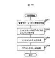
図16は、デバイスについての情報を管理マネージャから受け取ったサーバプログラムが実施する処理の流れを示すフローチャートである。 FIG. 16 is a flowchart showing the flow of processing executed by the server program that has received information about the device from the management manager.
管理マネージャ93からデバイスについての情報が渡されると(ステップ2201)、サーバプログラム94は、ファイルサーバ9のデバイスリコンフィグを実施する。この処理は、具体的には、図4に示した第1の実施形態におけるステップ1005の処理と同様の処理である(ステップ2202)。
When information about a device is passed from the management manager 93 (step 2201), the
続いて、サーバプログラム94は、新たにできたデバイスにファイルシステムを作成し(ステップ2203)、管理マネージャ93にそのファイルシステムのマウントポイントを示す情報を返却する(ステップ2204)。
Subsequently, the
以上の処理により、ホスト計算機1′から利用可能な新しいファイルシステムを追加することができる。 Through the above processing, a new file system that can be used from the host computer 1 'can be added.
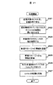
図17は、既存のファイルシステムのサイズを変更する際に管理マネージャ93により実施される処理の流れを示すフローチャートである。図15に示した新たなファイルシステムの要求時の処理とは、以下の点において相違する。
FIG. 17 is a flowchart showing the flow of processing performed by the
既存のファイルシステムのサイズを変更しようとするとき、ユーザ、あるいは、アプリケーションプログラムは、クライアントプログラム11′に対して、サイズを変更するファイルシステムのマウントポイント、拡張、あるいは、縮小しようとするサイズなどに関する情報を指定した要求を発行する。クライアントプログラム11′は、ユーザ、あるいは、アプリケーションプログラムから指定された情報を用いて管理マネージャ93にファイルシステムのサイズの変更を要求する。管理マネージャ93は、クライアントプログラム11′から送られてくる、処理の対象とするファイルシステムのマウントポイント、拡張したいサイズ等の情報を受け取る(ステップ2301)。
When attempting to change the size of an existing file system, the user or application program relates to the mount point of the file system whose size is to be changed, the size to be expanded or reduced, and the like for the
管理マネージャ93は、クライアントプログラム11′から受け取ったマウントポイントに基づいて処理の対象となっているファイルシステムを格納している論理デバイスのターゲットID、LUNなどの情報を得て、論理デバイスを判別する。そして、管理マネージャ93は、この論理デバイスの種類、すなわち、信頼性、性能等の情報を得る(ステップ2302)。続いて、管理マネージャ93は、ステップ2301、2302で得た情報に基づき、新たなファイルシステムを追加するときと同様にして、変更後のファイルシステムのサイズの空き領域を持ち、元の論理デバイスと同じ種類の論理デバイスを確保する(ステップ1102〜1110)。
The
この後、管理マネージャ93は、ステップ2304において、記憶装置サブシステム2に対し、これまでファイルシステムが記録されていた論理デバイスから新たに確保した論理デバイスにデータの移動を指示する。データの移動はファイルサーバプログラム94から透過的に行われる。ホスト計算機1′はファイルサーバプログラム94を介して記憶装置サブシステム2にアクセスするため、この処理は、ホスト計算機1′からも透過的な処理となる。したがって、データの移動中、ホスト計算機1′は処理を停止する必要はない。
Thereafter, in
データの移動が終わると、管理マネージャ93は、サーバプログラム94にファイルシステムの拡張を指示する。実際のデバイス容量が増加してもファイルシステムを構築しなおさなければ、ファイルシステムとしては拡張された容量のすべてを使うことはできない。サーバプログラム94に対してファイルシステムの拡張を指示した後、管理マネージャ93は、処理の完了をクライアントプログラム11′に通知して処理を終了する(ステップ2305)。
When the data movement is completed, the
以上の処理により、既存のファイルシステムのサイズの変更を、ホスト計算機1′を稼働させたまま行うことが可能となる。なお、既存のファイルシステムのサイズを変更する場合、クライアントプログラム11′は、管理マネージャからの通知を受けた後、そのまま拡張されたファイルシステムを使用することができる。したがって、この場合には、図14におけるステップ2004、及びステップ2005の処理は実施する必要がない。
Through the above processing, it is possible to change the size of the existing file system while the host computer 1 'is operating. When the size of the existing file system is changed, the client program 11 'can use the expanded file system as it is after receiving the notification from the management manager. Therefore, in this case, it is not necessary to carry out the processing of
図18は、本発明が適用された計算機システムの第4の実施形態における構成例を示す簡略なブロック図である。 FIG. 18 is a simplified block diagram showing a configuration example in the fourth embodiment of a computer system to which the present invention is applied.
本実施形態における計算機システムは、複数のホスト計算機1″(ホスト計算機1a″、1b″、・・・、1n″)、管理用ホスト計算機3、記憶装置サブシステム2′、副記憶装置5を有している。各ホスト計算機1″と記憶装置サブシステム2′は、ファイバチャネルスイッチ8を介して接続される。また、ホスト計算機1″、記憶装置サブシステム2′、ファイバチャネルスイッチ8は、ネットワーク4を介して相互に接続されている。
The computer system in the present embodiment includes a plurality of
ファイバチャネルスイッチ8は、複数のポート81を備えており、これらのポート間の接続を切り替え、ポート81に接続された機器間でのデータ転送を実現する。ファイバチャネルスイッチ8は、また、ネットワーク4を介して通信を行うためのネットワークインタフェース82を備える。ホスト計算機1″は、それぞれ、ボリュームマネージャ11″、1または複数のインタフェース12を備えている。ホスト計算機1″のインタフェース12は、ファイバチャネル8が有する複数のポート81のいずれかと接続される。
The fiber channel switch 8 includes a plurality of
記憶装置サブシステム2′は、複数のクラスタ26とクラスタ26を相互に接続するコントローラ間接続機構27を有する。各クラスタ26は、チャネルプロセッサ23′、ドライブプロセッサ22′、複数のディスクユニット21を備える。同じクラスタ内のチャネルプロセッサ23′とドライブプロセッサ22′とは、コントローラ間接続機構27よりも高速なバス28で結合されている。各チャネルプロセッサ23′は、1、または複数のポート231を備えており、副記憶装置5、あるいは、ファイバチャネル8を介してホスト計算機1″と接続される。ドライブプロセッサ22′には複数のディスクユニット21が接続されている。本実施形態では、これら複数のディスクユニット21を組み合わせて1または複数の論理デバイスが構成され、あるいは、1つのディスクユニット21により1または複数の論理デバイスが構成される。なお、ある1つの論理デバイスを構成するにあたって複数のクラスタ26が備えるディスクユニット21を組み合わせることはできないものとする。
The storage subsystem 2 'has a plurality of
チャネルプロセッサ23′は、各ホスト計算機1″に対し、1または複数の論理デバイスを見せ、各ホスト1″からのアクセスを受け付ける。原則として、チャネルプロセッサ23′は、そのチャネルプロセッサ23′が属するクラスタ26内のドライブプロセッサ22′に接続されたディスクユニット21により構成される論理デバイスを管理対象とする。これは同一クラスタ26内のチャネルプロセッサ23′とドライブプロセッサ22′の通信は、クラスタをまたがった通信よりも高速に行うことができることによる。ただし、障害などの要因により、あるクラスタ26のチャネルプロセッサ23′が動作しない場合には、他クラスタ26のチャネルプロセッサ23′がその処理を肩代わりする。チャネルプロセッサ23′はホスト計算機1″から指定された論理デバイスがどのドライブプロセッサ22′に接続されたディスクユニット21に構成されているか判別し、然るべきドライブプロセッサ22′に処理の要求を渡す。ドライブプロセッサ22′は、チャネルプロセッサ23′からの要求を解釈して、論理デバイスの置かれている各ディスクユニット21に対するディスクアクセス要求を生成して、該当するディスクユニット21にそのディスクアクセス要求を送る。
The
ホスト計算機1″は、第1の実施形態におけるホスト計算機1とほぼ同様の構成を有するが、その上で動作するボリュームマネージャ11″の機能に若干の相違がある。ボリュームマネージャ11″は、第1の実施形態においてボリュームマネージャ11が行う論理デバイスの割り当て、返却の処理に加え、複数の論理デバイスをまとめて、別の論理デバイスとして上位のアプリケーションプログラムに見せる機能を持つ。以下、ボリュームマネージャ11″が作る論理デバイスを、記憶装置サブシステム2′が管理する論理デバイスと区別するためLVOLと表記する。ボリュームマネージャ11″は、複数の論理デバイスを見かけ上結合してより大きな1つのLVOLを形成し、あるいは、1つの論理デバイスを複数の領域に分割し、それらの領域をLVOLとしてホスト計算機1″上のアプリケーションプログラムに利用させることができる。また、すでに存在するLVOLに新たな論理デバイスを結合して、LVOLの容量を拡張することもできる。
The
図19は、本実施形態においてボリュームを新規に割り当てる際にボリュームマネージ11″により実施される処理の流れを示すフローチャートである。ここで説明する処理は、図4に示した第1の実施形態におけるデバイスの割り当て処理のステップ1002がステップ1002′に、ステップ1006がステップ1005′、ステップ1006′に置き換えたものである。このほかのステップでは、図4の対応するステップと同様の処理が行われる。以下、ステップ1002′、1005′、及び1006′で行われる処理について説明する。
19 is a flowchart showing the flow of processing performed by the
ステップ1002′では、未使用のWWN、LUNの組をボリュームマネージャ11″が管理しているLVOL管理テーブルより検索する。LVOL管理テーブルの一例を図20に示す。LVOL管理テーブルには、LVOL名151、デバイスファイル名152、サイズ153、そして各デバイスのWWN154、LUN155の組からなる情報が登録される。LVOL名151は、ボリュームマネージャ11″によりアプリケーションプログラムに提供されているLVOLを識別するために付与される識別子である。デバイスファイル名152は、LVOLを構成する論理デバイスの名称である。ボリュームマネージャ11″は、各LVOLに属する論理デバイスをデバイスファイル名に基づいて管理している。サイズ153は、そのLVOLを構成する各論理デバイスの容量を示す。1つのLVOLが複数の論理デバイスで構成されることもあるため、1つのLVOL名に複数のデバイスファイルが属することもある。
In
ステップ1005′でボリュームマネージャ11″は、管理マネージャ31によって割り当てられた論理デバイスを用いて新たにLVOLを作成し、その内容をLVOL管理テーブルに登録する。ステップ1006′では、割り当ての済んだLVOL名がユーザに通知されて処理は終了する。
In
図21は、ユーザ、あるいは、アプリケーションプログラムの要求に応じてLVOLの容量を拡張する際のボリュームマネージャの処理を示すフローチャートである。 FIG. 21 is a flowchart showing the processing of the volume manager when the LVOL capacity is expanded in response to a request from the user or an application program.
LVOLの容量を拡張する際には、新たに論理デバイスが用意され、その論理デバイスを拡張しようとするLVOLを構成している論理デバイスと組み合わされて新しいLVOLが構築される。このとき新たに用意される論理デバイスは、拡張しようとするLVOLを構築している論理デバイスと同じ種類の論理デバイスであることが普通である。本実施形態では、ボリュームマネージャ11″が拡張しようとするLVOLを構成している論理デバイスの種類を判別し、同じ種類の論理デバイスを確保する。
When expanding the capacity of an LVOL, a new logical device is prepared, and a new LVOL is constructed in combination with the logical device that constitutes the LVOL to be expanded. At this time, the newly prepared logical device is usually the same type of logical device as the logical device constructing the LVOL to be expanded. In the present embodiment, the type of logical device constituting the LVOL to be expanded by the
本処理において、ボリュームマネージャ11″は、まず、ユーザあるいは、アプリケーションプログラムから拡張対象のLVOLのLVOL名と拡張すべき容量についての情報を受け取る(ステップ2501)。次に、ボリュームマネージャ11″は、拡張対象のLVOLを構成する論理デバイスの種類を管理マネージャ31に問い合わせる(ステップ2502)。ボリュームマネージャ11″は、未使用のWWN、LUNの組をLVOL管理テーブルより検索する(ステップ2503)。ボリュームマネージャ11″は、ステップ2502、2503で取得した論理デバイスの種類、及び未使用のWWNとLUNの組み合わせを含む情報を管理マネージャ31に送信する。(ステップ2504)。管理マネージャ31から新たに割り当てられた論理デバイスについての情報を受信すると(ステップ2505)、ボリュームマネージャ11″は、ホスト計算機1″のリコンフィグを実施し、新たに割り当てられた論理デバイスをホスト計算機1″から認識できるようにする(ステップ2506)。最後に、ボリュームマネージャ11″は、拡張対象のLVOLに新たに割り当てられた論理デバイスを追加してLVOLの容量を拡張し、処理を終了する(ステップ2507)。
In this processing, the
図19のステップ1003、及び図21のステップ2504でボリュームマネージャ11″から新しい論理ボリュームの割り当ての要求があると、管理マネージャ31は、いずれの場合もボリュームマネージャ11″から要求されたデバイスの種類、容量に見合ったデバイスを検索して割り当てる。この処理のために、管理マネージャ31は、図9に示すような論理デバイス管理テーブルの他、記憶装置サブシステム2′内のクラスタ26に関する情報が設定されたクラスタ情報テーブルを備える。
When there is a request for allocation of a new logical volume from the
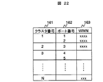
図22は、クラスタ情報管理テーブルの一例を示すテーブル構成図である。 FIG. 22 is a table configuration diagram illustrating an example of a cluster information management table.
クラスタ情報管理テーブルは、各クラスタ26に対応したエントリを有し、クラスタ26ごとにそのクラスタを識別するクラスタ番号161、クラスタが有するポートのポート番号162、及びポートに割り当てられているWWN163が設定されている。図に示すように、1つのクラスタ26に複数のポートが存在する場合、それぞれのポート番号とWWNがそのクラスタに対応したエントリに設定される。先に説明したように、あるドライブプロセッサ22′に接続されたディスクユニット21に論理デバイスを構築したときは、その論理デバイスに対しては同一のクラスタ内のポート231からアクセスできるようにすることが性能上の観点から望ましい。管理マネージャ31は、クラスタ情報テーブルに基づいてホスト計算機1″からのアクセスに用いられるポート231と、新しく割り当てる論理デバイスが構築されるディスクユニット21が接続するドライブプロセッサ22′が同じクラスタとなるようにデバイスの設定を行う。
The cluster information management table has an entry corresponding to each
図23は、管理マネージャ31によるデバイスの割り当て処理の流れを示すフローチャートである。
FIG. 23 is a flowchart showing the flow of device allocation processing by the
本実施形態におけるデバイスの割り当て処理は、図11に示した第2の実施形態における処理とほぼ同様に行われるが、記憶装置サブシステムの構成上の相違から一部の処理が第2の実施形態とは異なる。具体的には、ステップ1109において、管理マネージャ31から記憶装置サブシステム2′に対して新規にデバイスの構築が要求されると、記憶装置サブシステム2′は、要求に合わせてデバイスを構築する。記憶装置サブシステム2′において論理デバイスが構築されると、管理マネージャ31には、新しく構築された論理デバイスに関し、その論理デバイスがどのクラスタ26に構築されたかを示す情報を受け取る(ステップ2610)。
The device allocation process in this embodiment is performed in substantially the same manner as the process in the second embodiment shown in FIG. Is different. Specifically, in
管理マネージャ31は、記憶装置サブシステム2′から受け取った論理デバイスに関する情報と、クラスタ情報管理テーブルを参照して、どのポートから当該デバイスをアクセスできるようにするか決定する。管理マネージャ31は、さらに、未使用LUNの情報によって、新たに割り当てるデバイスのLUNを決定する(ステップ2604)。また、管理マネージャ31は、最後に、ボリュームマネージャ11″に対し、新しく割り当てる論理ボリュームのアクセスに必要なWWN、LUNなどの情報を送り、処理を終了する(ステップ2607)。
The
ここで説明した以外の処理については、図11に示した第2の実施形態における管理マネージャの処理と同様であり、図では、図11と同一の参照番号を用い、詳細な説明は省略する。 The processes other than those described here are the same as those of the management manager in the second embodiment shown in FIG. 11, and the same reference numerals as those in FIG.
以上説明した実施の形態によれば、ホスト計算機が稼働中であっても、要求にあわせてデバイスの割り当てを行うことができる。さらにファイバチャネルスイッチで構成された、複数のデバイスが混在するような環境でも、要求に合ったデバイスを容易にホスト計算機に割り当てることが可能となる。 According to the embodiment described above, device allocation can be performed in accordance with a request even when the host computer is operating. Furthermore, even in an environment in which a plurality of devices are configured with fiber channel switches, it is possible to easily assign devices that meet the requirements to the host computer.
なお、本発明は、上述した実施形態に限定されるものではなく、本発明の趣旨の範囲内において種々の態様をとり得るものであることは言うまでもない。
Needless to say, the present invention is not limited to the above-described embodiments, and can take various forms within the scope of the gist of the present invention.
1…ホスト計算機、
2…記憶装置サブシステム
3…管理用ホスト計算機
4…ネットワーク
5…副記憶装置
8…ファイバチャネルスイッチ
11…ボリュームマネージャ
21…ディスクユニット
22…ディスクコントローラ
23…ポート
31…管理マネージャ
81…ポート
1 ... Host computer,
2 ...
Claims (8)
前記記憶装置サブシステムがそれぞれ有する前記記憶デバイスに関するデバイス管理情報と、前記記憶デバイスの前記第1の計算機への割り当ての状態を示すホスト管理情報と、を有する第2の計算機と、を有し、
前記第1の計算機は、ユーザまたはアプリケーションプログラムからの新たな記憶デバイスの要求を受け付け、前記第2の計算機に新たな記憶デバイスの割り当てを要求する要求手段を有し、
前記第2の計算機は、前記要求手段からの要求に応じて、前記デバイス管理情報及び前記ホスト管理情報を参照して前記第1の計算機に割り当て可能な記憶デバイスを決定する手段、及び該決定手段により決定された記憶デバイスを前記第1の計算機からアクセス可能となるように前記記憶装置サブシステムの設定を変更する変更手段とを有することを特徴とする計算機システム。 A plurality of storage subsystems having a first computer and a storage device that holds data accessed from the first computer;
A second computer having device management information related to the storage device respectively included in the storage device subsystem and host management information indicating a state of assignment of the storage device to the first computer;
The first computer has request means for accepting a request for a new storage device from a user or an application program, and requesting the second computer to assign a new storage device;
The second computer determines a storage device that can be allocated to the first computer by referring to the device management information and the host management information in response to a request from the request unit, and the determination unit And a changing means for changing the setting of the storage subsystem so that the storage device determined by the method is accessible from the first computer.
前記第2の計算機は、前記変更の要求に応じて、容量の変更後における記憶デバイスに合致する記憶デバイスを選択する手段と、前記記憶装置サブシステムに対し、前記既存の記憶デバイスに保持されているデータを前記選択手段により選択された記憶デバイスに移動するよう指示する手段とを有し、
前記記憶装置サブシステムは、前記指示に応答してデータを移動する手段を有することを特徴とする請求項1記載の計算機システム。 The request means has means for accepting a request to change the capacity of an existing storage device and transmitting the request to the second computer,
In response to the change request , the second computer selects a storage device that matches the storage device after the capacity change, and is stored in the existing storage device for the storage subsystem. Means for instructing to move data to the storage device selected by the selection means,
2. The computer system according to claim 1, wherein the storage device subsystem has means for moving data in response to the instruction.
前記提供する手段は、新たに割り当てられた記憶デバイスを前記拡張が要求されたデバイスの一部とすることを特徴とする請求項7記載の計算機システム。 In response to a request for expansion of the capacity of a device already provided to the application program, the request means includes a new storage device having a capacity required for the expansion requested by the second computer to the expansion request. Request an assignment,
8. The computer system according to claim 7, wherein the providing means sets a newly allocated storage device as a part of the device requested to be expanded.
Priority Applications (1)
| Application Number | Priority Date | Filing Date | Title |
|---|---|---|---|
| JP2004184406A JP4501548B2 (en) | 1999-08-27 | 2004-06-23 | Computer system and device allocation method |
Applications Claiming Priority (2)
| Application Number | Priority Date | Filing Date | Title |
|---|---|---|---|
| JP24102499 | 1999-08-27 | ||
| JP2004184406A JP4501548B2 (en) | 1999-08-27 | 2004-06-23 | Computer system and device allocation method |
Related Parent Applications (1)
| Application Number | Title | Priority Date | Filing Date |
|---|---|---|---|
| JP2000238865A Division JP3843713B2 (en) | 1999-08-27 | 2000-08-02 | Computer system and device allocation method |
Publications (3)
| Publication Number | Publication Date |
|---|---|
| JP2004355638A JP2004355638A (en) | 2004-12-16 |
| JP2004355638A5 JP2004355638A5 (en) | 2007-09-06 |
| JP4501548B2 true JP4501548B2 (en) | 2010-07-14 |
Family
ID=34066715
Family Applications (1)
| Application Number | Title | Priority Date | Filing Date |
|---|---|---|---|
| JP2004184406A Expired - Fee Related JP4501548B2 (en) | 1999-08-27 | 2004-06-23 | Computer system and device allocation method |
Country Status (1)
| Country | Link |
|---|---|
| JP (1) | JP4501548B2 (en) |
Families Citing this family (12)
| Publication number | Priority date | Publication date | Assignee | Title |
|---|---|---|---|---|
| JP4681337B2 (en) * | 2005-04-06 | 2011-05-11 | 株式会社日立製作所 | Fiber channel switch device, information processing system, and login processing method |
| JP5020601B2 (en) * | 2006-11-10 | 2012-09-05 | 株式会社日立製作所 | Access environment construction system and method |
| JP5130764B2 (en) * | 2007-03-28 | 2013-01-30 | 日本電気株式会社 | Storage system, power saving method and program thereof |
| JP2010097372A (en) * | 2008-10-16 | 2010-04-30 | Hitachi Ltd | Volume management system |
| US9342801B2 (en) | 2010-03-29 | 2016-05-17 | Amazon Technologies, Inc. | Managing committed processing rates for shared resources |
| CA2792532C (en) * | 2010-03-29 | 2020-06-30 | Amazon Technologies, Inc. | Managing committed request rates for shared resources |
| US8694400B1 (en) | 2010-09-14 | 2014-04-08 | Amazon Technologies, Inc. | Managing operational throughput for shared resources |
| US8595460B2 (en) * | 2011-08-26 | 2013-11-26 | Vmware, Inc. | Configuring object storage system for input/output operations |
| US8650359B2 (en) * | 2011-08-26 | 2014-02-11 | Vmware, Inc. | Computer system accessing object storage system |
| US9367354B1 (en) | 2011-12-05 | 2016-06-14 | Amazon Technologies, Inc. | Queued workload service in a multi tenant environment |
| US8984243B1 (en) | 2013-02-22 | 2015-03-17 | Amazon Technologies, Inc. | Managing operational parameters for electronic resources |
| CN114185650B (en) * | 2021-12-14 | 2023-07-25 | 平安壹账通云科技(深圳)有限公司 | Method, system, equipment and storage medium for identifying SCSI equipment under Linux system |
Citations (1)
| Publication number | Priority date | Publication date | Assignee | Title |
|---|---|---|---|---|
| JP2001142648A (en) * | 1999-08-27 | 2001-05-25 | Hitachi Ltd | Computer system and its method for allocating device |
Family Cites Families (4)
| Publication number | Priority date | Publication date | Assignee | Title |
|---|---|---|---|---|
| JPH0448347A (en) * | 1990-06-18 | 1992-02-18 | Nec Corp | File area securing system for system including external storages of different types |
| JPH07334467A (en) * | 1994-06-07 | 1995-12-22 | Hitachi Ltd | Computer system |
| JPH0962463A (en) * | 1995-08-25 | 1997-03-07 | Fujitsu Ltd | Semiconductor disk drive |
| JP3641872B2 (en) * | 1996-04-08 | 2005-04-27 | 株式会社日立製作所 | Storage system |
-
2004
- 2004-06-23 JP JP2004184406A patent/JP4501548B2/en not_active Expired - Fee Related
Patent Citations (1)
| Publication number | Priority date | Publication date | Assignee | Title |
|---|---|---|---|---|
| JP2001142648A (en) * | 1999-08-27 | 2001-05-25 | Hitachi Ltd | Computer system and its method for allocating device |
Also Published As
| Publication number | Publication date |
|---|---|
| JP2004355638A (en) | 2004-12-16 |
Similar Documents
| Publication | Publication Date | Title |
|---|---|---|
| JP3843713B2 (en) | Computer system and device allocation method | |
| US6854034B1 (en) | Computer system and a method of assigning a storage device to a computer | |
| EP2652586B1 (en) | Information storage system and storage system management method | |
| US9639277B2 (en) | Storage system with virtual volume having data arranged astride storage devices, and volume management method | |
| TWI432959B (en) | Storage subsystem and storage system architecture performing storage virtualization and method thereof | |
| US7596637B2 (en) | Storage apparatus and control method for the same, and computer program product | |
| EP1837751B1 (en) | Storage system, storage extent release method and storage apparatus | |
| US7117336B2 (en) | Computer system for managing storage areas in a plurality of storage devices | |
| JP5341184B2 (en) | Storage system and storage system operation method | |
| WO2013118195A1 (en) | Storage management method and storage system in virtual volume having data arranged astride storage devices | |
| US9122415B2 (en) | Storage system using real data storage area dynamic allocation method | |
| JP2003345631A (en) | Computer system and allocating method for storage area | |
| WO2011135636A1 (en) | Computer system and method for controlling same | |
| EP4139802B1 (en) | Methods for managing input-ouput operations in zone translation layer architecture and devices thereof | |
| JP2007102760A (en) | Automatic allocation of volume in storage area network | |
| JP2003091449A (en) | Storage system and method for managing the same system | |
| JP4501548B2 (en) | Computer system and device allocation method | |
| US7676644B2 (en) | Data processing system, storage apparatus and management console | |
| US7827269B2 (en) | System and method for managing networked storage devices with a plurality of logical units | |
| US11061604B2 (en) | Method and storage system architecture for accessing data by means of a compatible module | |
| US20100082934A1 (en) | Computer system and storage system | |
| JP4258768B2 (en) | File placement system | |
| JP6019169B2 (en) | Information storage system |
Legal Events
| Date | Code | Title | Description |
|---|---|---|---|
| RD01 | Notification of change of attorney |
Free format text: JAPANESE INTERMEDIATE CODE: A7421 Effective date: 20060421 |
|
| A521 | Written amendment |
Free format text: JAPANESE INTERMEDIATE CODE: A523 Effective date: 20070724 |
|
| A621 | Written request for application examination |
Free format text: JAPANESE INTERMEDIATE CODE: A621 Effective date: 20070724 |
|
| A131 | Notification of reasons for refusal |
Free format text: JAPANESE INTERMEDIATE CODE: A131 Effective date: 20100112 |
|
| A521 | Written amendment |
Free format text: JAPANESE INTERMEDIATE CODE: A523 Effective date: 20100304 |
|
| TRDD | Decision of grant or rejection written | ||
| A01 | Written decision to grant a patent or to grant a registration (utility model) |
Free format text: JAPANESE INTERMEDIATE CODE: A01 Effective date: 20100330 |
|
| A01 | Written decision to grant a patent or to grant a registration (utility model) |
Free format text: JAPANESE INTERMEDIATE CODE: A01 |
|
| A61 | First payment of annual fees (during grant procedure) |
Free format text: JAPANESE INTERMEDIATE CODE: A61 Effective date: 20100412 |
|
| FPAY | Renewal fee payment (event date is renewal date of database) |
Free format text: PAYMENT UNTIL: 20130430 Year of fee payment: 3 |
|
| FPAY | Renewal fee payment (event date is renewal date of database) |
Free format text: PAYMENT UNTIL: 20130430 Year of fee payment: 3 |
|
| FPAY | Renewal fee payment (event date is renewal date of database) |
Free format text: PAYMENT UNTIL: 20140430 Year of fee payment: 4 |
|
| LAPS | Cancellation because of no payment of annual fees |