JP4499488B2 - Endoscopic puncture needle - Google Patents

Endoscopic puncture needle Download PDF

Info

Publication number
JP4499488B2
JP4499488B2 JP2004176041A JP2004176041A JP4499488B2 JP 4499488 B2 JP4499488 B2 JP 4499488B2 JP 2004176041 A JP2004176041 A JP 2004176041A JP 2004176041 A JP2004176041 A JP 2004176041A JP 4499488 B2 JP4499488 B2 JP 4499488B2
Authority
JP
Japan
Prior art keywords
needle
outer needle
puncture
inner needle
sheath
Prior art date
Legal status (The legal status is an assumption and is not a legal conclusion. Google has not performed a legal analysis and makes no representation as to the accuracy of the status listed.)
Expired - Fee Related
Application number
JP2004176041A
Other languages
Japanese (ja)
Other versions
JP2005349121A5 (en
JP2005349121A (en
Inventor
和也 雑賀
Current Assignee (The listed assignees may be inaccurate. Google has not performed a legal analysis and makes no representation or warranty as to the accuracy of the list.)
Olympus Corp
Original Assignee
Olympus Corp
Priority date (The priority date is an assumption and is not a legal conclusion. Google has not performed a legal analysis and makes no representation as to the accuracy of the date listed.)
Filing date
Publication date
Application filed by Olympus Corp filed Critical Olympus Corp
Priority to JP2004176041A priority Critical patent/JP4499488B2/en
Publication of JP2005349121A publication Critical patent/JP2005349121A/en
Publication of JP2005349121A5 publication Critical patent/JP2005349121A5/ja
Application granted granted Critical
Publication of JP4499488B2 publication Critical patent/JP4499488B2/en
Expired - Fee Related legal-status Critical Current
Anticipated expiration legal-status Critical

Links

Images

Description

本発明は、経内視鏡的に目的部位に穿刺して生体組織を採取するための内視鏡用穿刺針に関する。   The present invention relates to an endoscope puncture needle for collecting a living tissue by puncturing a target site through a transendoscope.

近年、超音波内視鏡による超音波断層像観察下において、超音波断層像をガイドにして鉗子等の処置具を挿通する処置具用チャンネルを介して長尺の穿刺針を観察部位まで誘導して病変組織に突刺し、体組織を採取して病理確定診断を行う手技が行われている。   In recent years, a long puncture needle has been guided to an observation site through a treatment instrument channel through which a treatment instrument such as a forceps is inserted using an ultrasonic tomogram as a guide while observing an ultrasonic tomogram with an ultrasonic endoscope. A technique for puncturing a diseased tissue, collecting a body tissue, and performing a pathological diagnosis has been performed.

このような診断を行うための穿刺針は、例えば、特許文献1に開示されている。この穿刺針は、先端部が鋭利な形状に形成された細長の針管内に、先端が鋭利な形状のスタイレットを挿脱自在に配置したものであり、超音波画像の観察下において、針管が目的部位まで到達したとき、スタイレットを吸引口金から引き抜き、吸引口金にシリンジ等を接続して体腔内組織の吸引を行う。
特開2003−190179号公報
A puncture needle for performing such a diagnosis is disclosed in Patent Document 1, for example. In this puncture needle, a stylet with a sharp tip is removably disposed in an elongated needle tube having a sharp tip, and the needle tube is observed while observing an ultrasonic image. When the target site is reached, the stylet is withdrawn from the suction cap, and a syringe or the like is connected to the suction cap to suck the tissue in the body cavity.
JP 2003-190179 A

特許文献1に開示されているように、従来の穿刺針では、針管が目的部位に到達するまでは、針管内にスタイレットを収納したまま穿刺している。しかしながら、針管とスタイレットとの間には、スタイレットを進退させるための僅かな空隙が存在し、特に、穿刺経路が長い深部の組織を採取するような場合には、針管内に目的部位以外の不要な組織が混入する虞があり、検査精度を向上する上での支障となる。   As disclosed in Patent Document 1, the conventional puncture needle is punctured with the stylet stored in the needle tube until the needle tube reaches the target site. However, there is a slight gap between the needle tube and the stylet to advance and retreat the stylet. Especially when a deep tissue with a long puncture path is collected, the needle tube has a region other than the target site. There is a possibility that unnecessary tissue may be mixed, which hinders improvement in inspection accuracy.

本発明は上記事情に鑑みてなされたもので、目的部位に穿刺して組織を採取する際に、目的部位以外の不要な組織が混入することを防止し、組織検査の精度を向上することのできる内視鏡用穿刺針を提供することを目的としている。   The present invention has been made in view of the above circumstances, and prevents an unnecessary tissue other than the target site from being mixed when the tissue is collected by puncturing the target site, thereby improving the accuracy of the tissue examination. An object of the present invention is to provide an endoscopic puncture needle.

上記目的を達成するため、本発明の一態様による内視鏡用穿刺針は、ースと、上記シース内に進退自在に挿通され、先端部周辺に外部に連通する連通口を設けると共に、この連通口を閉塞する可撓膜を配設した外針と、上記外針内に進退自在に挿通される中空状の内針と、上記シースの基端部が固定される操作部本体と、上記外針を上記操作部本体に対して進退自在に保持する外針スライドと、上記内針を上記外針に対して進退自在に保持し、上記内針を上記外針の上記可撓膜から外部に突出させて目的部位に穿刺可能とする内針スライダと、を備えている。 To achieve the above object, an endoscopic puncture needle according to an aspect of the present invention, a sheet over scan, is inserted retractably into the sheath, provided with a communication port that communicates with the outside peripheral tip, An outer needle provided with a flexible film that closes the communication port, a hollow inner needle that is inserted into the outer needle so as to be movable forward and backward, an operation portion main body to which the proximal end portion of the sheath is fixed, An outer needle slide for holding the outer needle with respect to the operation portion main body, and an inner needle with the outer needle being held with respect to the outer needle, the inner needle being removed from the flexible film of the outer needle. An inner needle slider that protrudes to the outside and enables puncture of a target site.

本発明による内視鏡用穿刺針は、目的部位に穿刺して組織を採取する際に、先端部周辺の外部に連通する連通口を可撓膜で閉塞した外針を目的部位近傍まで穿刺し、外針から内針を突出させて目的部位の組織を採取することが可能であるため、採取した組織に目的部位以外の不要な組織が混入することを防止することができ、組織検査の精度を向上することができる。   The puncture needle for an endoscope according to the present invention punctures an outer needle close to the target site by closing a communication port communicating with the outside around the distal end portion with a flexible film when collecting the tissue by puncturing the target site. Since it is possible to extract the tissue at the target site by projecting the inner needle from the outer needle, it is possible to prevent unnecessary tissue other than the target site from being mixed into the collected tissue, and the accuracy of the tissue examination Can be improved.

以下、図面を参照して本発明の実施の形態を説明する。図1〜図16は本発明の実施の一形態に係り、図1は内視鏡装置の全体構成図、図2は外針及び内針を突出させた状態の内視鏡用穿刺針の外観図、図3はシース内に外針及び内針を収納した状態の内視鏡用穿刺針の外観図、図4は外針及び内針の構成を示す説明図、図5は外針及び内針の他の構成例を示す説明図、図6は外針及び内針の更に他の構成例を示す説明図、図7は操作部の構成を示す説明図、図8は図7のA部拡大図、図9は図7のB部拡大図、図10は図7のC部拡大図、図11は穿刺針の取付けを示す説明図であり、図11(a)は穿刺針を処置具用チャンネル入口に固定した状態を示す図、図11(b)はシースを処置具用チャンネル出口から突出した状態を示す図、図12は外針の操作状態を示す説明図であり、図12(a)は外針を突出させたときの穿刺針を示す図、図12(b)はシースから外針を突出させた状態を示す図、図13は内針の操作状態を示す説明図であり、図13(a)は外針から内針を突出させたときの穿刺針を示す図、図13(b)は外針から内針を突出させた状態を示す図、図14は穿刺針による吸引生検の開始を示す説明図であり、図14(a)は穿刺針にシリンジを装着した状態を示す説明図、図14(b)は内針からスタイレットを抜き取った状態を示す説明図、図15は吸引生検時の操作を示す説明図であり、図15(a)は穿刺針のアジテーション操作を示す図、図15(b)は内針の動きを示す図、図16は吸引生検終了後の状態を示す説明図であり、図16(a)は穿刺針からシリンジを取り外した状態を示す図、図16(b)は内針を抜き取った後の外針を示す図である。   Embodiments of the present invention will be described below with reference to the drawings. 1 to 16 relate to an embodiment of the present invention, FIG. 1 is an overall configuration diagram of an endoscope apparatus, and FIG. 2 is an external view of an endoscope puncture needle with an outer needle and an inner needle protruding. 3 is an external view of the puncture needle for an endoscope in a state where the outer needle and the inner needle are housed in the sheath, FIG. 4 is an explanatory view showing the configuration of the outer needle and the inner needle, and FIG. 6 is an explanatory diagram showing another configuration example of the needle, FIG. 6 is an explanatory diagram showing still another configuration example of the outer needle and the inner needle, FIG. 7 is an explanatory diagram showing the configuration of the operation unit, and FIG. 8 is an A portion of FIG. FIG. 9 is an enlarged view of part B of FIG. 7, FIG. 10 is an enlarged view of part C of FIG. 7, FIG. 11 is an explanatory view showing attachment of the puncture needle, and FIG. FIG. 11B is a diagram showing a state in which the sheath is protruded from the treatment instrument channel outlet, FIG. 12 is an explanatory diagram showing an operation state of the outer needle, and FIG. ) Is a view showing the puncture needle when the outer needle is protruded, FIG. 12B is a view showing a state where the outer needle is protruded from the sheath, and FIG. 13 is an explanatory view showing an operation state of the inner needle, 13A is a view showing the puncture needle when the inner needle is protruded from the outer needle, FIG. 13B is a view showing a state where the inner needle is protruded from the outer needle, and FIG. 14 is aspiration by the puncture needle. It is explanatory drawing which shows the start of a biopsy, Fig.14 (a) is explanatory drawing which shows the state which mounted | wore the puncture needle, FIG.14 (b) is explanatory drawing which shows the state which extracted the stylet from the inner needle, 15A and 15B are explanatory views showing operations during aspiration biopsy. FIG. 15A is a diagram showing the agitation operation of the puncture needle, FIG. 15B is a diagram showing the movement of the inner needle, and FIG. It is explanatory drawing which shows the state after completion | finish of a test | inspection, FIG.16 (a) is a figure which shows the state which removed the syringe from the puncture needle, FIG. (B) is a diagram showing an outer needle After removing the inner needle.

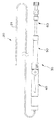
図1に示す内視鏡装置1は、本実施の形態においては、超音波を送受するための超音波振動子(例えばコンベックス型等の超音波振動子)3を先端部に備えた超音波内視鏡2と、超音波振動子3の駆動及び走査、エコー信号の処理等を行って超音波画像を生成する超音波観測装置15とを基本構成として備えている。超音波内視鏡2には、超音波画像の観察下において、目的部位に突刺して体組織や体液を採取するための内視鏡用穿刺針(以下、単に「穿刺針」と記載する)20を着脱自在に装着することができる。   In the present embodiment, an endoscope apparatus 1 shown in FIG. 1 includes an ultrasonic transducer (for example, an ultrasonic transducer such as a convex type) 3 for transmitting and receiving ultrasonic waves at its distal end. The basic configuration includes an endoscope 2 and an ultrasonic observation device 15 that generates an ultrasonic image by driving and scanning the ultrasonic transducer 3, processing an echo signal, and the like. The ultrasonic endoscope 2 has an endoscope puncture needle (hereinafter simply referred to as “puncture needle”) for puncturing a target site and collecting body tissue or fluid under observation of an ultrasound image. 20 can be detachably mounted.

超音波内視鏡2は、体腔内に挿入される細長の可撓性を有する挿入部4を有し、この挿入部4の先端側に超音波振動子3を備えると共に、後端側に操作部5及び接眼部6を備えている。操作部5の側部からは、ユニバーサルコード7が延出され、このユニバーサルコード7の末端に、超音波観測装置15に接続される超音波コネクタ8が設けられている。また、ユニバーサルコード7の中途部からは、光源用ケーブル9が分岐され、この光源用ケーブル9の末端に、図示しない光源装置に接続される内視鏡コネクタ10が設けられている。   The ultrasonic endoscope 2 has an elongated flexible insertion portion 4 to be inserted into a body cavity. The ultrasonic endoscope 2 includes an ultrasonic transducer 3 on the distal end side of the insertion portion 4 and is operated on the rear end side. A part 5 and an eyepiece part 6 are provided. A universal cord 7 is extended from the side of the operation unit 5, and an ultrasonic connector 8 connected to the ultrasonic observation device 15 is provided at the end of the universal cord 7. A light source cable 9 is branched from the middle portion of the universal cord 7, and an endoscope connector 10 connected to a light source device (not shown) is provided at the end of the light source cable 9.

また、超音波内視鏡2の操作部5先端側には、鉗子等の処置具を挿通するための処置具用チャンネルの入口口金11が設けられている。この処置具用チャンネルの入口口金11には、穿刺針20が着脱自在に螺合固定されるようになっており、以下に説明するように、超音波振動子3の超音波走査面内に突出させた外針22から更に内針23を突出させて目的部位に穿刺することにより、体組織や体液を採取することができる。   In addition, at the distal end side of the operation section 5 of the ultrasonic endoscope 2, an inlet cap 11 for a treatment instrument channel for inserting a treatment instrument such as a forceps is provided. The puncture needle 20 is detachably screwed and fixed to the inlet base 11 of the treatment instrument channel, and protrudes into the ultrasonic scanning plane of the ultrasonic transducer 3 as described below. By further projecting the inner needle 23 from the outer needle 22 that has been made to puncture the target site, body tissue or body fluid can be collected.

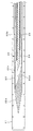
穿刺針20は、図2に示すように、内視鏡の処置具用チャンネルに挿入される細長のパイプ状のシース21と、このシース21の基端部に配置された把持部を兼ねる操作部35と、操作部35を介してシース21内に進退自在に挿通配置される外針22と、外針22内に進退自在に挿通配置され、外針22から突出されて目的部位の体組織や体液を採取するための内針23とを主として構成されている。   As shown in FIG. 2, the puncture needle 20 includes an elongated pipe-shaped sheath 21 that is inserted into a treatment instrument channel of an endoscope, and an operation unit that also serves as a gripping part disposed at the proximal end of the sheath 21. 35, an outer needle 22 that is inserted and disposed in the sheath 21 through the operation unit 35 so as to be movable forward and backward, and an outer needle 22 that is inserted and disposed in the outer needle 22 so as to be movable forward and backward. An inner needle 23 for collecting body fluid is mainly configured.

尚、本形態においては、穿刺針20は、使い捨てタイプとして構成され、シース21は、コスト低減が可能な、ポリエーテルサルホンやテフロン(登録商標)等の樹脂部材で形成される。ポリエーテルサルホンやテフロン(登録商標)は、用途に応じて使い分けられる。   In this embodiment, the puncture needle 20 is configured as a disposable type, and the sheath 21 is formed of a resin member such as polyethersulfone or Teflon (registered trademark) that can reduce the cost. Polyethersulfone and Teflon (registered trademark) are properly used depending on the application.

操作部35は、シース21の基端部が固設される操作部本体40と、操作部本体40に対して摺動自在に設けられ、外針22を進退させる外針スライダ50と、外針スライダ50に対して摺動自在に設けられ、内針23を進退させる内針スライダ60とで主に構成されている。図3に示すように、穿刺針20を使用しない状態では、外針スライダ50は、操作部本体40から離間する方向に引き延ばされた位置で固定(後述するストッパ用の固定ネジ53により固定;図7参照)され、この状態では、外針22の先端部はシース21内に配置されている。   The operation unit 35 includes an operation unit main body 40 to which the proximal end portion of the sheath 21 is fixed, an outer needle slider 50 that is slidable with respect to the operation unit main body 40, and moves the outer needle 22 forward and backward. The slider 50 is slidably provided, and mainly includes an inner needle slider 60 that moves the inner needle 23 forward and backward. As shown in FIG. 3, when the puncture needle 20 is not used, the outer needle slider 50 is fixed at a position extended in a direction away from the operation section main body 40 (fixed by a stopper fixing screw 53 described later). ; See FIG. 7), and in this state, the distal end portion of the outer needle 22 is disposed in the sheath 21.

シース21内に配置される外針22は、例えばステンレス等の金属材で形成され、図4に示すように、細長のパイプ状の針管部22aと、この針管部22aの先端を閉塞する鋭利な形状の先端部22bとを備えた形状に形成されている。外針22の内部には、同様にステンレス等の金属材で形成され、先端が鋭利な形状のパイプ状の内針23と、内針23内に挿脱自在に配置される先端が鋭利な形状のスタイレット24とが収納されている。   The outer needle 22 disposed in the sheath 21 is made of, for example, a metal material such as stainless steel. As shown in FIG. 4, the outer needle 22 has a slender pipe-shaped needle tube portion 22a and a sharp tip that closes the tip of the needle tube portion 22a. It is formed in a shape provided with a shape tip portion 22b. The outer needle 22 is similarly formed of a metal material such as stainless steel, and has a pipe-shaped inner needle 23 having a sharp tip and a sharp tip that is removably disposed in the inner needle 23. The stylet 24 is housed.

また、外針22の先端部22bの基部側面には、外針22の外部と内部とを連通させて内針23及びスタイレット24を進退可能とするための内針出入口部22cが設けられている。この内針出入口部22cは、先端が閉塞された外針22の内部と外部とを連通する連通口であり、針管部22aから先端部22bにかけての内孔端部に形成された傾斜面22dを案内として、内針23及びスタイレット24が側方に突出可能となっている。この内針出入口部22cは、内針23及びスタイレット24を外部に突出させない状態では、開口周縁に接着や溶着等によって固着された可撓膜25によって閉塞されている。   Further, an inner needle inlet / outlet portion 22c is provided on the base side surface of the distal end portion 22b of the outer needle 22 to allow the inner needle 23 and the stylet 24 to advance and retract by communicating the outside and the inside of the outer needle 22. Yes. The inner needle inlet / outlet portion 22c is a communication port that communicates the inside and the outside of the outer needle 22 with the tip closed, and has an inclined surface 22d formed at the inner hole end portion from the needle tube portion 22a to the tip portion 22b. As a guide, the inner needle 23 and the stylet 24 can protrude sideways. When the inner needle 23 and the stylet 24 are not projected to the outside, the inner needle inlet / outlet portion 22c is closed by a flexible film 25 fixed to the peripheral edge of the opening by adhesion or welding.

可撓膜25は、医療用材料としての適性を有し、且つ可撓性を有する材料、例えば、ラテックスや高分子樹脂材料等によって形成され、内針23及びスタイレット24を可撓膜25から突出可能とすると共に、吸引生検後に内針23を外針22内に収納したときの内針出入口部22cの閉塞性を回復可能としている。   The flexible film 25 has suitability as a medical material and is formed of a flexible material such as latex or a polymer resin material, and the inner needle 23 and the stylet 24 are separated from the flexible film 25. In addition to being able to protrude, it is possible to recover the closing property of the inner needle entrance / exit portion 22c when the inner needle 23 is housed in the outer needle 22 after the suction biopsy.

すなわち、所定の部位を観察し、更に、その奥の部位の組織を採取して検査を行う必要が生じた場合、先端が開口されていない外針22を目的部位の近傍まで穿刺し、その位置で外針22から内針23を突出させて目的部位の組織を吸引・採取し、内針23を外針22内に収納したとき、可撓膜25によって外針22の開口が閉じられるため、目的部位以外の不要な組織の混入(以下、「コンタミネーション」と称する)を防止することができ、検査精度を向上することができる。   That is, when it is necessary to observe a predetermined part and further collect and examine the tissue in the back part, the outer needle 22 whose tip is not opened is punctured to the vicinity of the target part, and the position When the inner needle 23 protrudes from the outer needle 22 and the tissue of the target site is sucked and collected and the inner needle 23 is stored in the outer needle 22, the opening of the outer needle 22 is closed by the flexible film 25. It is possible to prevent contamination of unnecessary tissue other than the target site (hereinafter referred to as “contamination”), and to improve inspection accuracy.

この場合、図4においては、可撓膜25を外針22の先端側部に部分的に設ける例を示しているが、図5に示すように、チューブ状の可撓膜27を用いても良い。   In this case, FIG. 4 shows an example in which the flexible film 25 is partially provided on the distal end side portion of the outer needle 22. However, as shown in FIG. good.

図5の例では、外針22を変更した外針26を用いている。この外針26は、外針22と同様の形状、すなわち、パイプ状の針管部26a、この針管部26aの先端を閉塞する鋭利な形状の先端部26b、内針23(及びスタイレット24)の外針26からの出し入れための内針出入口部26c及び傾斜面26dを備えており、更に、先端部26b基部外周に、凹部をなす段部26eが全周に渡って形成されている。   In the example of FIG. 5, an outer needle 26 in which the outer needle 22 is changed is used. The outer needle 26 has the same shape as the outer needle 22, that is, a pipe-shaped needle tube portion 26a, a sharp-shaped distal end portion 26b that closes the distal end of the needle tube portion 26a, and the inner needle 23 (and the stylet 24). An inner needle inlet / outlet portion 26c and an inclined surface 26d for taking in and out of the outer needle 26 are provided, and a step portion 26e forming a recess is formed on the outer periphery of the distal end portion 26b over the entire circumference.

チューブ状の可撓膜27は、外針26外周の段部26eに取り付けられ、内針出入口部26cを除く部分が接着や溶着等によって外針26に固定される。これにより、組付け作業性が向上するばかりでなく、固着面積が拡大し、可撓膜27をより強固に外針26に固着することができる。   The tube-shaped flexible film 27 is attached to a step portion 26e on the outer periphery of the outer needle 26, and a portion other than the inner needle inlet / outlet portion 26c is fixed to the outer needle 26 by adhesion or welding. Thereby, not only the assembly workability is improved, but also the fixing area is enlarged, and the flexible film 27 can be fixed to the outer needle 26 more firmly.

また、外針26は、外針22に比較して針管部26aを短くし、針管部26aの末端に樹脂材等で形成される外針用シース28を冠着・固定している。樹脂材料で形成した外針用シース28内には、内針23及びスタイレット24が挿通配置されることから、必要な穿刺力を得る上での剛性を確保しつつ、コスト低減を図ることができる。   Further, the outer needle 26 has a needle tube portion 26a shorter than the outer needle 22, and a sheath 28 for outer needle formed of a resin material or the like is crowned and fixed to the end of the needle tube portion 26a. Since the inner needle 23 and the stylet 24 are inserted and disposed in the outer needle sheath 28 formed of a resin material, it is possible to reduce costs while ensuring rigidity for obtaining a necessary puncture force. it can.

更に、図4及び図5は、内針23を外針22の側方に突出させる例を示しているが、図6に示すように、内針23及びスタイレット24を外針の長手軸方向前面に突出させるようにしても良い。すなわち、ステンレスパイプ等の部材を軸方向に対して斜めにカットして刃面を形成した外針29を用い、刃面開口部を内針出入口部として、この内針出入口部を封止する可撓膜体30を設ける。   4 and 5 show an example in which the inner needle 23 protrudes to the side of the outer needle 22, but as shown in FIG. 6, the inner needle 23 and the stylet 24 are arranged in the longitudinal direction of the outer needle. You may make it protrude on the front. That is, an outer needle 29 having a blade surface formed by cutting a member such as a stainless pipe obliquely with respect to the axial direction is used, and the inner needle inlet / outlet portion can be sealed using the blade surface opening as an inner needle inlet / outlet portion. A flexure body 30 is provided.

可撓膜体30は、外針29の刃面形状に沿った可撓膜30aと、この可撓膜30aを端部に有する円筒状の装着部30bとを備えた形状であり、外針29の刃面開口から所定深さに設けた円筒状のざぐり部29aに、装着部30bを接着或いは溶着する。この場合、可撓膜体30は、成型によって製作することにより、製造コストを低減することが可能となるが、必ずしも全体を可撓性の材料で形成する必要はなく、外針29の刃面開口を封止する可撓膜30aのみに可撓性を有する材料を用い、装着部30bは硬質材料で形成しても良い。   The flexible membrane body 30 has a shape including a flexible membrane 30 a that follows the shape of the blade surface of the outer needle 29, and a cylindrical mounting portion 30 b that has the flexible membrane 30 a at its end. The mounting portion 30b is bonded or welded to a cylindrical counterbore portion 29a provided at a predetermined depth from the blade surface opening. In this case, it is possible to reduce the manufacturing cost by manufacturing the flexible film body 30 by molding. However, the flexible film body 30 is not necessarily formed of a flexible material as a whole, and the blade surface of the outer needle 29 is not necessarily formed. A material having flexibility may be used only for the flexible film 30a that seals the opening, and the mounting portion 30b may be formed of a hard material.

また、外針29は、外針26と同様に短く形成し、外針用シース28に固着・接続する。但し、外針26とシース28との接続が外針26にシース28を被せる形式であるのに対し、外針29とシース28との接続は、外針29内にシース28を嵌め込む接続形式とする。   Further, the outer needle 29 is formed short like the outer needle 26 and is fixedly connected to the outer needle sheath 28. However, the connection between the outer needle 26 and the sheath 28 is a type in which the outer needle 26 is covered with the sheath 28, whereas the connection between the outer needle 29 and the sheath 28 is a connection type in which the sheath 28 is fitted into the outer needle 29. And

また、本実施の形態においては、内針23内にスタイレット24を挿通・配置する例について説明しているが、外針22の先端部を完全に閉塞して目的部位近傍まで穿刺し、その位置で内針23を外針22から突出させるため、スタイレット24を省略することも可能である。   Further, in the present embodiment, an example in which the stylet 24 is inserted and arranged in the inner needle 23 is described. However, the distal end portion of the outer needle 22 is completely closed and punctured to the vicinity of the target site. Since the inner needle 23 protrudes from the outer needle 22 at the position, the stylet 24 can be omitted.

次に、以上の外針22及び内針23の進退操作を行うための操作部35の構成例について、図7〜図10を参照し、操作部本体40、外針スライダ50、内針スライダ60の順に説明する。   Next, with reference to FIGS. 7 to 10, the configuration example of the operation unit 35 for performing the above-described advance / retreat operation of the outer needle 22 and the inner needle 23 will be described with reference to FIGS. 7 to 10. Will be described in the order.

図7及び図8に示すように、操作部本体40は、後述する外針スライダ50の外針操作管51が摺動自在に収納される細長のパイプ状のスライダ収納管41を主として構成されている。スライダ収納管41は、先端部の内径が外針操作管51の外径よりも小径に形成され、超音波内視鏡2の処置具用チャンネルの入口口金11に連結固定される2条ネジ(雌ネジ)を形成した接続ネジ42とシース21の基端部を固定するシース口金部材43とが順に配設されている。また、スライダ収納管41の後端部には、外針操作管51の抜け止めとなるキャップ部材44が螺合されている。   As shown in FIGS. 7 and 8, the operation section main body 40 is mainly configured by an elongated pipe-shaped slider storage tube 41 in which an outer needle operation tube 51 of an outer needle slider 50 described later is slidably stored. Yes. The slider storage tube 41 is formed with a double thread (the inner diameter of the distal end portion is smaller than the outer diameter of the outer needle operation tube 51) and is connected and fixed to the inlet base 11 of the treatment instrument channel of the ultrasonic endoscope 2. A connection screw 42 in which a female screw) is formed and a sheath base member 43 that fixes the proximal end portion of the sheath 21 are disposed in this order. In addition, a cap member 44 that prevents the outer needle operation tube 51 from coming off is screwed to the rear end portion of the slider storage tube 41.

接続ネジ42は、スライダ収納管41の先端部に螺合されて内設され、スライダ収納管41の先端部に径方向に螺設された止めネジ45によって固定されている。シース口金部材43は、接続ネジ42によって固定されるフランジ部43aの前後に、ボス部43bを突出した形状に形成され、このボス部43bの内周面と、スライダ収納管41の先端部内に固設される管状部材46の外周面との間に、シース21を挟持して固定している。シース21内の外針22は、シース21から手元側に延出されて管状部材46内を挿通され、外針操作管51の先端に固定されている。   The connection screw 42 is screwed into the distal end portion of the slider storage tube 41 and is fixed by a set screw 45 screwed in the radial direction at the distal end portion of the slider storage tube 41. The sheath base member 43 is formed in a shape in which a boss portion 43 b protrudes before and after the flange portion 43 a fixed by the connection screw 42, and is fixed to the inner peripheral surface of the boss portion 43 b and the distal end portion of the slider storage tube 41. The sheath 21 is sandwiched and fixed between the outer peripheral surface of the tubular member 46 provided. The outer needle 22 in the sheath 21 extends from the sheath 21 to the proximal side, is inserted through the tubular member 46, and is fixed to the distal end of the outer needle operation tube 51.

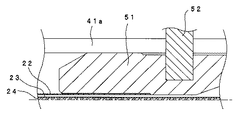
外針スライダ50は、図7及び図9に示すように、後述する内針スライダ60の内針操作管61が摺動自在に収納される細長のパイプ状の外針操作管51を主として構成されている。外針操作管51は、先端部の内径が内針操作管61の外径よりも小径に形成され、この先端部に外針22の末端が固設されると共に、径方向にピン52が立設されてスライダ収納管41に形成された案内溝41aから突出されている。   As shown in FIGS. 7 and 9, the outer needle slider 50 is mainly composed of an elongated pipe-shaped outer needle operation tube 51 in which an inner needle operation tube 61 of an inner needle slider 60 described later is slidably accommodated. ing. The outer needle operating tube 51 is formed so that the inner diameter of the distal end portion is smaller than the outer diameter of the inner needle operating tube 61, and the distal end of the outer needle 22 is fixed to the distal end portion, and the pin 52 stands in the radial direction. It is provided and protrudes from a guide groove 41 a formed in the slider storage tube 41.

この案内溝41aは、外針操作管51を長手方向に摺動移動させる際の案内となるものであり、この案内溝41aから突出するピン52の先端部に、外針操作管51を所望の位置に固定するストッパ用としての固定ネジ53が螺合されている。尚、案内溝41aは、外針22のシース21からの最大突出長さを規定するスライダ収納管41の先端側の位置から、スライダ収納管41の末端まで形成されている。   The guide groove 41a serves as a guide when the outer needle operation tube 51 is slid and moved in the longitudinal direction. The outer needle operation tube 51 is provided at a distal end portion of the pin 52 protruding from the guide groove 41a. A fixing screw 53 as a stopper for fixing to a position is screwed. The guide groove 41 a is formed from the position on the distal end side of the slider storage tube 41 that defines the maximum protruding length of the outer needle 22 from the sheath 21 to the end of the slider storage tube 41.

製品の出荷時には、ピン52を介して外針操作管51がスライダ収納管41の基端側(固定ネジ53下部がキャップ部材44に当接する位置)に配置され、固定ネジ53が所定のトルクで締結されている。この状態では、固定ネジ53及び外針操作管51がスライダ収納管41の側壁を押圧して外針操作管51が固定され、この外針操作管51に固設される外針22の先端部がシース21内にあって突出しない配置状態となる。   When the product is shipped, the outer needle operation tube 51 is disposed on the proximal end side of the slider storage tube 41 (a position where the lower portion of the fixing screw 53 abuts against the cap member 44) via the pin 52, and the fixing screw 53 has a predetermined torque. It is concluded. In this state, the fixing screw 53 and the outer needle operation tube 51 press the side wall of the slider storage tube 41 to fix the outer needle operation tube 51, and the distal end portion of the outer needle 22 fixed to the outer needle operation tube 51 is fixed. Is in the sheath 21 and does not protrude.

また、外針操作管51の後端部には、キャップ部材55が螺合され、このキャップ部材55の内周面と内針操作管61の外周面との間に、Oリング56が介装されている。このOリング56は、内針23による吸引生検時に、外気が侵入することを防止するためのシールである。   A cap member 55 is screwed into the rear end portion of the outer needle operation tube 51, and an O-ring 56 is interposed between the inner peripheral surface of the cap member 55 and the outer peripheral surface of the inner needle operation tube 61. Has been. The O-ring 56 is a seal for preventing outside air from entering during suction biopsy using the inner needle 23.

次に、内針スライダ60について説明する。内針スライダ60は、図7及び図10に示すように、内針23(及びスタイレット24)が摺動自在に挿通配置される内針操作管61と、この内針操作管61の後端に固設される連結部材62に、着脱自在に螺合される吸引口金部材63とを主として構成されている。   Next, the inner needle slider 60 will be described. As shown in FIGS. 7 and 10, the inner needle slider 60 includes an inner needle operation tube 61 into which the inner needle 23 (and the stylet 24) is slidably inserted and a rear end of the inner needle operation tube 61. A suction base member 63 that is detachably screwed to a connecting member 62 fixed to the main body is mainly configured.

吸引口金部材63は、連結部材62に螺合される雌ネジ部63aと、吸引生検時にシリンジ等を装着するための口金部63bとを備え、雌ネジ部63aの内径側に、連結部材62内に嵌挿されるボス部63cが形成されている。このボス部63cには、内針23の末端が固設されており、この内針23内に挿通されるスタイレット24の末端が、口金部63bに着脱自在に取り付けられるスタイレット口金部材64に固設されている。   The suction cap member 63 includes a female screw portion 63a screwed to the connecting member 62 and a cap portion 63b for mounting a syringe or the like at the time of suction biopsy, and on the inner diameter side of the female screw portion 63a, the connecting member 62 is provided. A boss portion 63c to be inserted into the inside is formed. The end of the inner needle 23 is fixed to the boss portion 63c, and the end of the stylet 24 inserted into the inner needle 23 is attached to a stylet base member 64 that is detachably attached to the base portion 63b. It is fixed.

尚、内針操作管61には、内針23の外針22からの突出方向を予め認知可能なように、外針操作管51との合せマーク等を設けることが望ましい。この場合、操作部本体40は、スライダ収納管41を、接続ネジ42及びシース口金部材43による処置具用チャンネル入口への接続部分で分離し、相対回転可能な構成にしても良い。このような回転取付構造は、本出願人による特開2001−275947号公報に、固定リングとシリンダとによる回転構造として開示されている。   The inner needle operation tube 61 is preferably provided with an alignment mark with the outer needle operation tube 51 so that the protruding direction of the inner needle 23 from the outer needle 22 can be recognized in advance. In this case, the operation unit main body 40 may be configured such that the slider storage tube 41 is separated at the connection portion to the treatment instrument channel inlet by the connection screw 42 and the sheath base member 43 and can be relatively rotated. Such a rotation mounting structure is disclosed in Japanese Patent Application Laid-Open No. 2001-275947 by the present applicant as a rotation structure including a fixing ring and a cylinder.

また、外針22,内針23の先端部の所定位置表面には、複数の円環状の溝を、例えば長手方向に設けることが望ましく、この円環状の溝により、超音波振動子3から出射された超音波の反射エコーを超音波振動子3により多く反射させて超音波画像を明瞭に描出可能とする共に、外針22,内針23と目的部位との位置関係及び距離を精度良く把握することが可能となる。   In addition, it is desirable to provide a plurality of annular grooves in the longitudinal direction, for example, in the longitudinal direction on the surfaces of the distal end portions of the outer needle 22 and the inner needle 23, and the ultrasonic transducer 3 emits the annular grooves. The reflected ultrasonic echoes are reflected by the ultrasonic transducer 3 so that an ultrasonic image can be clearly depicted, and the positional relationship and distance between the outer needle 22 and the inner needle 23 and the target portion are accurately grasped. It becomes possible to do.

次に、上述のように構成された穿刺針20の使用法について、観察部位から更に深部にある目的部位の生検を行う場合を例に取り、図11〜図16を参照して説明する。   Next, a method of using the puncture needle 20 configured as described above will be described with reference to FIGS. 11 to 16, taking as an example a case where a biopsy of a target site deeper than the observation site is performed.

先ず、超音波内視鏡2の挿入部4の先端を目的部位近傍に対向するように挿入配置し、この状態で、穿刺針20のシース21を操作部5に設けられた入口口金11から処置具用チャンネル内に導入していく。そして、穿刺針20の操作部本体40を入口口金11に螺合・固定する。   First, the distal end of the insertion portion 4 of the ultrasonic endoscope 2 is inserted and disposed so as to face the vicinity of the target site, and in this state, the sheath 21 of the puncture needle 20 is treated from the inlet base 11 provided in the operation portion 5. It will be introduced into the equipment channel. Then, the operation portion main body 40 of the puncture needle 20 is screwed and fixed to the inlet base 11.

このとき、図11(a)に示すように、穿刺針20は、外針スライダ50が操作部本体40から長さL1だけ延出された略最後端の位置で固定ネジ53により固定され、内針スライダ60が外針スライダ50から長さL2だけ延出された初期位置にあるため、図11(b)に示すように、シース21が挿入部4先端の処置具用チャンネル出口より僅かに突出されている。従って、内針23及びスタイレット24は外針22内に収納され、外針22がシース21内に収納された状態となっている。   At this time, as shown in FIG. 11A, the puncture needle 20 is fixed by the fixing screw 53 at the position of the most rear end where the outer needle slider 50 is extended from the operation portion main body 40 by the length L1. Since the needle slider 60 is in the initial position extended by the length L2 from the outer needle slider 50, the sheath 21 slightly protrudes from the treatment instrument channel outlet at the distal end of the insertion portion 4 as shown in FIG. Has been. Therefore, the inner needle 23 and the stylet 24 are stored in the outer needle 22, and the outer needle 22 is stored in the sheath 21.

次に、挿入部4先端の超音波振動子3を体腔壁70に当接しての超音波走査による超音波画像の観察下において、体腔壁70に比較的近い観察部位71及び観察部位71の奥にある目的部位72の位置を確認する。そして、図12(a)に示すように、固定ネジ53を緩めて外針スライダ50を操作部本体40側にスライドさせ、図12(b)に示すように、外針22をシース21から突出させて観察部位71よりも深部の目的部位72の近傍の部位まで穿刺する。   Next, under observation of an ultrasonic image by ultrasonic scanning with the ultrasonic transducer 3 at the distal end of the insertion portion 4 in contact with the body cavity wall 70, an observation site 71 that is relatively close to the body cavity wall 70 and the back of the observation site 71 The position of the target site 72 is confirmed. Then, as shown in FIG. 12A, the fixing screw 53 is loosened and the outer needle slider 50 is slid toward the operation unit main body 40, and the outer needle 22 protrudes from the sheath 21 as shown in FIG. 12B. Then, puncture is performed up to a site near the target site 72 deeper than the observation site 71.

このとき、内針スライダ60を外針スライダ50から長さL2だけ延出された初期位置に保持したまま、外針スライダ50が操作部本体40から長さL1’の位置に縮められ(L1’<L1)、その位置で、固定ネジ53を締め込んで外針22の位置を強固に固定する。この状態では、外針22の先端部は完全に閉塞されているため、検査対象でない不要な組織が外針22内に入ることはない。   At this time, while holding the inner needle slider 60 at the initial position extended from the outer needle slider 50 by the length L2, the outer needle slider 50 is contracted from the operation portion main body 40 to the position of the length L1 ′ (L1 ′). <L1) At that position, the fixing screw 53 is tightened to firmly fix the position of the outer needle 22. In this state, the distal end portion of the outer needle 22 is completely occluded, so that unnecessary tissue that is not a subject of inspection does not enter the outer needle 22.

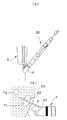
次に、超音波画像を観察しながら、図13(a)に示すように、内針スライダ60を外針スライダ50側にスライドさせ、図13(b)に示すように、外針22の可撓膜25を破って内針23及びスタイレット24を突出させ、目的部位72の内部まで内針23及びスタイレット24を穿刺する。この状態では、外針スライダ50が操作部本体40から長さL1’の位置に固定されたまま、内針スライダ60が外針スライダ50から長さL2’の位置に縮められる(L2’<L2)。   Next, while observing the ultrasonic image, the inner needle slider 60 is slid toward the outer needle slider 50 as shown in FIG. 13A, and the outer needle 22 is allowed to move as shown in FIG. 13B. The inner needle 23 and the stylet 24 are protruded by breaking the flexible film 25, and the inner needle 23 and the stylet 24 are punctured to the inside of the target site 72. In this state, the inner needle slider 60 is contracted from the outer needle slider 50 to the position of the length L2 ′ while the outer needle slider 50 is fixed to the position of the length L1 ′ from the operation portion main body 40 (L2 ′ <L2 ).

そして、内針23が目的部位72まで到達したことを確認したなら、内針スライダ60の吸引口金部材63からスタイレット口金部材64を外してスタイレット24を吸引口金部材63から引き抜き、図14(a)に示すように、吸引口金部材63の口金部63bにシリンジ65を接続する。これにより、図14(b)に示すように、目的部位72内で内針23の先端が開口され、組織の吸引が可能となる。   When it is confirmed that the inner needle 23 has reached the target portion 72, the stylet base member 64 is removed from the suction base member 63 of the inner needle slider 60, and the stylet 24 is pulled out from the suction base member 63, and FIG. As shown to a), the syringe 65 is connected to the cap part 63b of the suction cap member 63. As a result, as shown in FIG. 14B, the distal end of the inner needle 23 is opened in the target site 72, and the tissue can be aspirated.

この目的部位72の組織を吸引・採取する際には、図15(a)に示すように、シリンジ65を取り付けた状態で内針スライダ60を所定量ΔSだけ進退させる操作を繰返し、図15(b)に示すように、内針23内からの吸引に加えて内針23の機械的な押し出しによって組織を取り込む動作(アジテーション)を併用し、目的部位72の組織を採取する。   When the tissue of the target site 72 is aspirated / collected, as shown in FIG. 15A, the operation of moving the inner needle slider 60 forward and backward by a predetermined amount ΔS with the syringe 65 attached is repeated. As shown in b), in addition to the suction from the inner needle 23, the operation of taking in the tissue by mechanical push-out of the inner needle 23 (agitation) is used together to collect the tissue of the target site 72.

その後、図16(a)に示すように、シリンジ65及び吸引口金部材63を内針スライダ60の連結部材62から外して内針23を引き抜き、採取した組織の検査を行う。万一、組織の採取量が不十分であった場合には、図16(b)に示すように、外針22は目的部位72の近傍の位置に保持されているため、新しい内針を外針22内に挿通することにより、目的部位72の組織の採取を再度行うことができる。   Thereafter, as shown in FIG. 16A, the syringe 65 and the suction cap member 63 are detached from the connecting member 62 of the inner needle slider 60, the inner needle 23 is pulled out, and the collected tissue is inspected. If the amount of collected tissue is insufficient, the outer needle 22 is held at a position near the target site 72 as shown in FIG. By inserting into the needle 22, the tissue of the target site 72 can be collected again.

以上の操作によって内針23内に採取された組織は、目的部位72の近傍まで穿刺する外針22を完全に閉塞して組織採取機能を与えていないことから、コンタミネーションの虞がなく、精度の高い検査が可能となる。   Since the tissue collected in the inner needle 23 by the above operation does not give the tissue collection function by completely closing the outer needle 22 that punctures to the vicinity of the target site 72, there is no risk of contamination and accuracy. High inspection is possible.

そして、組織の採取量が検査に十分な量であり、検査が終了した後は、外針22をシース21に収納して穿刺針20を超音波内視鏡2の操作部5から取外し、穿刺針20を廃棄する。この場合、操作部本体40のキャップ部材44をスライダ収納管41から外すことにより、外針スライダ50を操作部本体40から分離することができ、また、スライダ収納管41先端の接続ネジ42,シース口金部材43を緩めることにより、シース21を操作部本体40から取り外すことができることから、厳重な洗滌・滅菌の管理下において、操作部本体40のみを再利用することも可能である。   The amount of tissue collected is sufficient for the examination, and after the examination is completed, the outer needle 22 is housed in the sheath 21 and the puncture needle 20 is removed from the operation section 5 of the ultrasonic endoscope 2 and puncture is performed. The needle 20 is discarded. In this case, the outer needle slider 50 can be separated from the operation unit main body 40 by removing the cap member 44 of the operation unit main body 40 from the slider storage tube 41, and the connecting screw 42 and sheath at the tip of the slider storage tube 41 are provided. By loosening the cap member 43, the sheath 21 can be removed from the operation portion main body 40. Therefore, only the operation portion main body 40 can be reused under strict cleaning and sterilization management.

尚、以上の穿刺針20の使用例は、観察部位71より更に深部の目的部位72の組織を採取する例であるが、体腔表面の組織を採取する際には、外針22を体組織に穿刺することなく、外針22から内針23を突出させて体組織を吸引・採取するといったように、通常の外針のみの穿刺針と同様の使用法も可能である。これにより、通常の穿刺針と本実施形態の穿刺針20とを交換・使い分けするといった煩雑さを解消することができる。   The use example of the puncture needle 20 described above is an example in which the tissue of the target site 72 deeper than the observation site 71 is sampled. However, when the tissue on the body cavity surface is sampled, the outer needle 22 is used as the body tissue. A method of use similar to a normal puncture needle with only an outer needle is also possible, such as causing the inner needle 23 to protrude from the outer needle 22 without puncturing and sucking and collecting body tissue. Thereby, it is possible to eliminate the trouble of exchanging and using the normal puncture needle and the puncture needle 20 of the present embodiment.

本発明は、以上述べた実施形態のみに限定されるものではなく、発明の要旨を逸脱しない範囲で種々変形実施可能である。   The present invention is not limited to the embodiments described above, and various modifications can be made without departing from the spirit of the invention.

内視鏡装置の全体構成図Overall configuration diagram of endoscope apparatus 外針及び内針を突出させた状態の内視鏡用穿刺針の外観図External view of puncture needle for endoscope with outer needle and inner needle protruding シース内に外針及び内針を収納した状態の内視鏡用穿刺針の外観図External view of endoscope puncture needle with outer needle and inner needle housed in sheath 外針及び内針の構成を示す説明図Explanatory drawing which shows the structure of an outer needle and an inner needle 外針及び内針の他の構成例を示す説明図Explanatory drawing which shows the other structural example of an outer needle and an inner needle 外針及び内針の更に他の構成例を示す説明図Explanatory drawing which shows the further another structural example of an outer needle and an inner needle. 操作部の構成を示す説明図Explanatory drawing showing the configuration of the operation unit 図7のA部拡大図Part A enlarged view of FIG. 図7のB部拡大図Part B enlarged view of FIG. 図7のC部拡大図Part C enlarged view of FIG. 穿刺針の取付けを示す説明図Explanatory drawing showing attachment of puncture needle 外針の操作状態を示す説明図Explanatory drawing showing the operating state of the outer needle 内針の操作状態を示す説明図Explanatory drawing showing the operating state of the inner needle 穿刺針による吸引生検の開始を示す説明図Explanatory drawing showing the start of aspiration biopsy with a puncture needle 吸引生検における穿刺針の操作を示す説明図Explanatory drawing which shows operation of the puncture needle in aspiration biopsy 吸引生検終了後の状態を示す説明図Explanatory drawing showing the state after the end of aspiration biopsy

符号の説明Explanation of symbols

2 超音波内視鏡
11 入口口金
20 内視鏡用穿刺針
21 シース
22 外針
23 内針
25 可撓膜
40 操作部本体
50 外針スライダ
60 内針スライダ
代理人 弁理士 伊 藤 進
2 Ultrasound Endoscope 11 Entrance Cap 20 Endoscope Puncture Needle 21 Sheath 22 Outer Needle 23 Inner Needle 25 Flexible Film 40 Operation Unit Main Body 50 Outer Needle Slider 60 Inner Needle Slider
Agent Patent Attorney Susumu Ito

Claims (4)

ースと、
上記シース内に進退自在に挿通され、先端部周辺に外部に連通する連通口を設けると共に、この連通口を閉塞する可撓膜を配設した外針と、
上記外針内に進退自在に挿通される中空状の内針と、
上記シースの基端部が固定される操作部本体と、
上記外針を上記操作部本体に対して進退自在に保持する外針スライドと、
上記内針を上記外針に対して進退自在に保持し、上記内針を上記外針の上記可撓膜から外部に突出させて目的部位に穿刺可能とする内針スライダと、
を備えたことを特徴とする内視鏡用穿刺針。
And death over vinegar,
An outer needle that is inserted into the sheath so as to be able to advance and retreat, and has a communication port that communicates with the outside around the tip, and a flexible film that closes the communication port is disposed;
A hollow inner needle that is inserted into the outer needle so as to freely advance and retract;
An operation portion main body to which the proximal end portion of the sheath is fixed;
An outer needle slide that holds the outer needle movably forward and backward with respect to the operation unit main body;
An inner needle slider that holds the inner needle so as to be movable back and forth with respect to the outer needle, and projects the inner needle to the outside from the flexible film of the outer needle so as to be able to puncture a target site;
A puncture needle for an endoscope, comprising:
上記外針の連通口を上記外針の先端部の側面に設け、上記可撓膜によって閉塞したことを特徴とする請求項1に記載の内視鏡用穿刺針。   The puncture needle for an endoscope according to claim 1, wherein a communication port of the outer needle is provided on a side surface of a distal end portion of the outer needle and is closed by the flexible film. 上記外針の連通口を上記外針の先端部の前面に設け、上記可撓膜によって閉塞したことを特徴とする請求項1に記載の内視鏡用穿刺針。   The puncture needle for an endoscope according to claim 1, wherein a communication port of the outer needle is provided on a front surface of a distal end portion of the outer needle and is closed by the flexible film. 上記内針スライダの後端に、上記内針の内部を吸気通路として吸引する吸引手段を着脱自在に接続可能な口金部を設けたことを特徴とする請求項1〜3の何れか一つに記載の内視鏡用穿刺針。   4. A base part to which a suction means for sucking the inside of the inner needle as an intake passage is detachably connectable is provided at the rear end of the inner needle slider. The puncture needle for endoscope as described.
JP2004176041A 2004-06-14 2004-06-14 Endoscopic puncture needle Expired - Fee Related JP4499488B2 (en)

Priority Applications (1)

Application Number Priority Date Filing Date Title
JP2004176041A JP4499488B2 (en) 2004-06-14 2004-06-14 Endoscopic puncture needle

Applications Claiming Priority (1)

Application Number Priority Date Filing Date Title
JP2004176041A JP4499488B2 (en) 2004-06-14 2004-06-14 Endoscopic puncture needle

Publications (3)

Publication Number Publication Date
JP2005349121A JP2005349121A (en) 2005-12-22
JP2005349121A5 JP2005349121A5 (en) 2007-07-19
JP4499488B2 true JP4499488B2 (en) 2010-07-07

Family

ID=35584055

Family Applications (1)

Application Number Title Priority Date Filing Date
JP2004176041A Expired - Fee Related JP4499488B2 (en) 2004-06-14 2004-06-14 Endoscopic puncture needle

Country Status (1)

Country Link
JP (1) JP4499488B2 (en)

Families Citing this family (9)

* Cited by examiner, † Cited by third party
Publication number Priority date Publication date Assignee Title
US8357103B2 (en) * 2003-10-14 2013-01-22 Suros Surgical Systems, Inc. Vacuum assisted biopsy needle set
WO2009149474A1 (en) 2008-06-06 2009-12-10 Vital Access Corporation Tissue management methods, apparatus, and systems
US11197952B2 (en) 2009-01-29 2021-12-14 Advent Access Pte. Ltd. Vascular access ports and related methods
WO2010088532A1 (en) 2009-01-29 2010-08-05 Vital Access Corporation Vascular access ports and related methods
JP5144833B2 (en) * 2010-04-08 2013-02-13 学校法人 久留米大学 Suction puncture device
JP5544278B2 (en) * 2010-11-04 2014-07-09 Hoya株式会社 Ultrasound endoscope puncture needle device
JP5809939B2 (en) * 2011-11-16 2015-11-11 Hoya株式会社 Ultrasound endoscope puncture needle
CN104684600B (en) 2012-07-26 2018-06-05 新加坡科技研究局 Vascular access equipment and leader
US9205229B2 (en) * 2013-10-24 2015-12-08 Avent, Inc. Catheter advancement device

Citations (3)

* Cited by examiner, † Cited by third party
Publication number Priority date Publication date Assignee Title
JPH1142232A (en) * 1997-07-25 1999-02-16 Olympus Optical Co Ltd Treatment utensil for endoscope having curve
JP2000507119A (en) * 1996-02-13 2000-06-13 イマジン メディカル インコーポレイティド Surgical access device and method of configuring a surgical access device
JP2000342590A (en) * 1999-06-02 2000-12-12 Olympus Optical Co Ltd Mucus collection device for endoscope

Patent Citations (3)

* Cited by examiner, † Cited by third party
Publication number Priority date Publication date Assignee Title
JP2000507119A (en) * 1996-02-13 2000-06-13 イマジン メディカル インコーポレイティド Surgical access device and method of configuring a surgical access device
JPH1142232A (en) * 1997-07-25 1999-02-16 Olympus Optical Co Ltd Treatment utensil for endoscope having curve
JP2000342590A (en) * 1999-06-02 2000-12-12 Olympus Optical Co Ltd Mucus collection device for endoscope

Also Published As

Publication number Publication date
JP2005349121A (en) 2005-12-22

Similar Documents

Publication Publication Date Title
EP2636375B1 (en) Tool for biopsy and tissue collecting method
JP4884046B2 (en) Ultrasound endoscope
JP5489418B2 (en) Ultrasonic probe hood and ultrasonic probe
JP3594278B2 (en) Intracavity ultrasonic probe device
JP5144833B2 (en) Suction puncture device
CA2588853A1 (en) Rotating fine needle for core tissue sampling
JP5908198B1 (en) Needle tube
JPH08117232A (en) Biopsy needle
JP2010274123A (en) Puncturing needle for endoscope
JP4533615B2 (en) Puncture needle and ultrasonic endoscope system
JP4499488B2 (en) Endoscopic puncture needle
JP3661470B2 (en) Tissue collection device
EP2617363B1 (en) Specimen collection treatment instrument
JP5226908B1 (en) Biopsy instrument
US20230329740A1 (en) Systems and methods for surgical procedures using torque driven guide wire
JP4311963B2 (en) Biopsy needle
JPH04307050A (en) Aspiration biopsy apparatus
JP5963977B1 (en) Rigid endoscope set
JP2001070307A (en) Tissue collecting apparatus
JP4339539B2 (en) Ultrasound puncture needle
JP4578868B2 (en) Endoscopic puncture needle
JP3042299B2 (en) Puncture treatment tool
JP5572781B1 (en) Ultrasonic probe system
JP7315707B2 (en) Biopsy needle and tissue sampling device
JP4395601B2 (en) Ultrasonic inspection equipment

Legal Events

Date Code Title Description
A621 Written request for application examination

Free format text: JAPANESE INTERMEDIATE CODE: A621

Effective date: 20070517

A521 Written amendment

Free format text: JAPANESE INTERMEDIATE CODE: A523

Effective date: 20070604

TRDD Decision of grant or rejection written
A01 Written decision to grant a patent or to grant a registration (utility model)

Free format text: JAPANESE INTERMEDIATE CODE: A01

Effective date: 20100323

A01 Written decision to grant a patent or to grant a registration (utility model)

Free format text: JAPANESE INTERMEDIATE CODE: A01

A61 First payment of annual fees (during grant procedure)

Free format text: JAPANESE INTERMEDIATE CODE: A61

Effective date: 20100415

FPAY Renewal fee payment (event date is renewal date of database)

Free format text: PAYMENT UNTIL: 20130423

Year of fee payment: 3

R151 Written notification of patent or utility model registration

Ref document number: 4499488

Country of ref document: JP

Free format text: JAPANESE INTERMEDIATE CODE: R151

FPAY Renewal fee payment (event date is renewal date of database)

Free format text: PAYMENT UNTIL: 20140423

Year of fee payment: 4

S531 Written request for registration of change of domicile

Free format text: JAPANESE INTERMEDIATE CODE: R313531

R350 Written notification of registration of transfer

Free format text: JAPANESE INTERMEDIATE CODE: R350

R250 Receipt of annual fees

Free format text: JAPANESE INTERMEDIATE CODE: R250

LAPS Cancellation because of no payment of annual fees