JP4498862B2 - Coating method and coating apparatus - Google Patents
Coating method and coating apparatus Download PDFInfo
- Publication number
- JP4498862B2 JP4498862B2 JP2004257052A JP2004257052A JP4498862B2 JP 4498862 B2 JP4498862 B2 JP 4498862B2 JP 2004257052 A JP2004257052 A JP 2004257052A JP 2004257052 A JP2004257052 A JP 2004257052A JP 4498862 B2 JP4498862 B2 JP 4498862B2
- Authority
- JP
- Japan
- Prior art keywords
- substrate
- coating
- nozzle
- unit
- stage
- Prior art date
- Legal status (The legal status is an assumption and is not a legal conclusion. Google has not performed a legal analysis and makes no representation as to the accuracy of the status listed.)
- Expired - Fee Related
Links
Images


Description
本発明は、被処理基板上に液体を塗布して塗布膜を形成するための塗布方法および塗布装置に関する。 The present invention relates to a coating method and a coating apparatus for forming a coating film by coating a liquid on a substrate to be processed.
従来より、LCD等のフラットパネルディスプレイ(FPD)の製造プロセスにおけるフォトリソグラフィー工程では、被処理基板(ガラス基板等)上にレジスト液をスピンレス法で塗布するために、スリット状の吐出口を有する長尺型のレジストノズルが用いられている。 2. Description of the Related Art Conventionally, in a photolithography process in a manufacturing process of a flat panel display (FPD) such as an LCD, in order to apply a resist solution onto a substrate to be processed (such as a glass substrate) by a spinless method, a length having a slit-like discharge port A long resist nozzle is used.
このような長尺型のレジストノズルを用いる塗布装置では、たとえば特許文献1に開示されるように、載置台またはステージ上に基板を水平に載置して、このステージ上の基板と長尺型レジストノズルの吐出口との間に100μm程度の微小なギャップを設定し、基板上方でレジストノズルを走査方向(一般にノズル長手方向と直交する水平方向)に移動させながら基板上にレジスト液を吐出させる。その際、基板上に吐出されたレジスト液がレジストノズルの背面下部に回って盛り上がり、ノズル長手方向に延びる凸面状のメニスカスが形成される。このメニスカスの頂上ラインまたはウエットラインが水平一直線に揃っていないと、基板上に形成されるレジスト塗布膜に膜厚の不均一性または塗布ムラが生ずる。この対策として、従来より、レジスト塗布処理を開始する直前にレジストノズルの背面下部にレジスト液を下塗りするプライミング処理が行われている。
In a coating apparatus using such a long resist nozzle, for example, as disclosed in
代表的なプライミング処理法は、レジストノズルと同等またはそれ以上の長さを有する円筒状または円柱状のローラ(プライミングローラ)をステージの隣に設置し、微小なギャップを介してプライミングローラの外周面と対向する位置までレジストノズルを近づけてレジスト液を吐出させ、同時にプライミングローラを所定方向に回転させる。そうすると、レジストノズルの吐出口より出たレジスト液はノズルの背面下部に回り込んでからプライミングローラに巻き取られ、プライミングローラからレジストノズルを離した後もノズル背面下部にレジスト液の液膜が残る。このプライミング処理を施されたレジストノズルを基板の上方に移し、塗布開始位置で基板との間に上記ギャップを形成する高さ位置まで下降させる。 A typical priming method is to install a cylindrical or columnar roller (priming roller) having a length equal to or longer than that of the resist nozzle next to the stage, and through the minute gap, the outer peripheral surface of the priming roller The resist nozzle is brought close to a position opposed to the nozzle to discharge the resist solution, and at the same time, the priming roller is rotated in a predetermined direction. Then, the resist solution discharged from the discharge port of the resist nozzle wraps around the lower portion of the back surface of the nozzle and is wound around the priming roller, and a resist solution liquid film remains at the lower portion of the back surface of the nozzle even after the resist nozzle is separated from the priming roller. . The resist nozzle that has been subjected to the priming process is moved above the substrate and lowered to a height position at which the gap is formed between the substrate and the substrate at the application start position.
図18に、レジストノズルを塗布開始位置まで下ろしたときの状態を示す。図示のように、レジストノズル200の背面下部に付着していたレジスト液の液膜202が設定距離dのギャップをビード状に塞ぐようにして基板Gに付着する。この状態から、レジストノズル200よりレジスト液の吐出を開始させるとともに、走査方向(図18の矢印Jの方向)への水平移動を開始させる。そうすると、レジストノズル200の吐出口よりレジスト液が帯状に出てノズル背面下部に凸面状のメニスカスがスムースに形成され、レジストノズルの走査移動に伴って基板Gの一端(塗布開始位置)から他端に向かって平坦にレジスト液の塗布膜が塗布される。
しかしながら、上記のようなプライミング処理にもばらつきがあり、レジストノズル200の背面下部にレジスト液の液膜が均一に付かないこともある。従来は、レジストノズル200を水平走査時だけでなく昇降時も常に水平姿勢で上下動させるため、塗布開始位置でレジストノズル200を下降させてノズル下端の吐出口と基板Gとの間に所望のギャップdを形成した際に、たとえば図19に示すように、ノズル長手方向においてレジスト液の液膜202が少ない箇所(図示の例では中間部付近)204で基板Gに着かない着液不良が発生することがあった。このような着液不良箇所のある状態で塗布走査を実行すると、図20に示すように、レジストノズル200の背面下部に形成されるメニスカスの頂上ライン(ウエットライン)WLが着液不良箇所204で落ち込み、その位置に対応するレジスト塗布膜206上の位置で走査方向に筋状の塗布ムラ208が生じるという問題が生じた。
However, there is also variation in the priming process as described above, and the resist film may not be uniformly applied to the lower part of the back surface of the
本発明は、かかる従来技術の問題点に鑑みてなされたもので、塗布開始位置で長尺型の塗布ノズル側から被処理基板へのギャップを介した着液を安定確実かつ良好に行って基板上に塗布ムラのない均一な塗布膜を形成できるようにした塗布方法および塗布装置を提供することを目的とする。 The present invention has been made in view of the problems of the prior art, and stably and satisfactorily and satisfactorily performs liquid deposition through the gap from the long coating nozzle side to the substrate to be processed at the coating start position. It is an object of the present invention to provide a coating method and a coating apparatus that can form a uniform coating film without coating unevenness.
上記の目的を達成するために、本発明の塗布方法は、ほぼ水平な被処理基板と長尺型の塗布ノズルの下端面に設けられた吐出口との間に所望の微小なギャップを設定し、前記塗布ノズルをノズル長手方向とほぼ直交する水平方向に相対的に移動させて、前記基板上に前記処理液を塗布する塗布方法であって、塗布処理に先立ち前記塗布ノズルの下端部に処理液の液膜を付ける第1の工程と、前記第1の工程の後に塗布開始位置で前記塗布ノズルを前記基板の上方から前記塗布ノズルの吐出口と前記基板との間に前記ギャップが形成される高さ位置まで下降させる第2の工程とを有し、前記第2の工程で、前記塗布ノズルの長手方向における一方の端部と他方の端部との間で前記高さ位置まで下りるタイミングを前記一方の端部よりも前記他方の端部が遅れるようにずらし、前記塗布ノズルの下端部の液膜を先に下りた前記一方の端部側から後に下りた前記他方の端部側に向かって連続的に前記基板に付着させる。 In order to achieve the above object, the coating method of the present invention sets a desired minute gap between a substantially horizontal substrate to be processed and a discharge port provided at the lower end surface of a long coating nozzle. A coating method for coating the processing liquid on the substrate by moving the coating nozzle in a horizontal direction substantially perpendicular to the longitudinal direction of the nozzle, and processing the lower end portion of the coating nozzle prior to the coating process. The gap is formed between the first step of applying a liquid film of liquid and the coating nozzle from above the substrate at the coating start position after the first step, between the discharge port of the coating nozzle and the substrate. A second step of lowering to a height position, and in the second step, a timing of descending to the height position between one end and the other end in the longitudinal direction of the coating nozzle The other end than the other end Shifted so that the end portion is delayed, adhere to continuously said substrate toward said the other end side that down after from the one end side of the lower end portion of the liquid film downlink earlier of the coating nozzle.
本発明の塗布方法においては、塗布ノズルの一方の端部が先に塗布開始位置の高さ位置まで下りる。これにより、塗布ノズルの下端部に付いている液膜はノズル長手方向において最初に該一方の端部から基板に付着する。その後少し遅れて塗布ノズルの他方の端部が塗布開始位置の高さ位置まで下りる。そうすると、塗布ノズルの下端部の液膜は、一方の端部から他方の端部に向かって連続的に基板に着液(付着)する。つまり、塗布ノズルの一方の端部で液膜が基板に付着したことによって生じた基板上のぬれがノズル長手方向に方向性をもって他方の端部に向かって広がり、途中で塗布ノズル側に液膜の少ない箇所があっても、基板上のぬれの勢いでその付近でも着液し、塗布ノズルと基板とのギャップを塞ぐ液膜が他方の端部までビード状に連続的につながって延びる。こうして、塗布開始位置において、水平姿勢の塗布ノズルの吐出口と基板との間に設定距離のギャップが形成されるとともに、該ギャップをノズル長手方向に一端から他端まで隙間なくビード状に液膜が塞いだ状態となる。この状態で塗布処理が開始されることにより、塗布ノズルの吐出口より帯状に出た処理液がスムースにノズル背面下部に回り込んでノズル長手方向にほぼ均一に延びる凸面状のメニスカスが形成される。このことによって、着液不良に起因する筋状の塗布ムラを防止することができる。 In the coating method of the present invention, one end of the coating nozzle first descends to the height position of the coating start position. Thereby, the liquid film attached to the lower end portion of the coating nozzle first adheres to the substrate from the one end portion in the nozzle longitudinal direction. Thereafter, the other end of the application nozzle descends to a height position at the application start position with a slight delay. If it does so, the liquid film of the lower end part of an application | coating nozzle will adhere | attach (attach) to a board | substrate continuously from one edge part toward the other edge part. That is, the wetting on the substrate caused by the liquid film adhering to the substrate at one end of the coating nozzle spreads toward the other end with directionality in the nozzle longitudinal direction, and the liquid film on the coating nozzle side in the middle Even if there is a small portion, the liquid is deposited even in the vicinity of the substrate due to the momentum of wetting on the substrate, and the liquid film closing the gap between the coating nozzle and the substrate continuously extends in a bead shape to the other end. Thus, at the coating start position, a gap of a set distance is formed between the discharge port of the horizontal coating nozzle and the substrate, and the gap is formed into a bead-like liquid film without gap from one end to the other end in the nozzle longitudinal direction. Is closed. When the coating process is started in this state, the processing liquid that has come out in a strip shape from the discharge port of the coating nozzle smoothly wraps around the lower part of the back surface of the nozzle to form a convex meniscus extending substantially uniformly in the longitudinal direction of the nozzle. . As a result, streaky coating unevenness due to poor liquid deposition can be prevented.
本発明の好適な一態様によれば、第1の工程で、塗布ノズルの長手方向に延びる円筒状または円柱状のローラの頂上部付近に微小なギャップを介して塗布ノズルの吐出口から処理液を吐出させ、吐出口から出た処理液が塗布ノズルの背面側に回り込む方向にローラを回転させる。かかるプライミング処理によって、塗布ノズルの下端部に、特に吐出口からノズル背面にかけて処理液の液膜を付着させることができる。 According to a preferred aspect of the present invention, in the first step, the treatment liquid is discharged from the discharge port of the application nozzle through a minute gap near the top of a cylindrical or columnar roller extending in the longitudinal direction of the application nozzle. And the roller is rotated in a direction in which the processing liquid coming out of the discharge port wraps around the back side of the coating nozzle. By such priming treatment, a liquid film of the treatment liquid can be attached to the lower end portion of the coating nozzle, particularly from the discharge port to the back surface of the nozzle.
また、本発明の第1の塗布装置は、被処理基板をほぼ水平に載置するステージと、前記基板上に処理液を塗布するために前記ステージ上の基板に対して上方から処理液を吐出する長尺型の塗布ノズルと、前記塗布ノズルをその長手方向と直交する水平方向で前記ステージに対して相対的に移動させる水平移動部と、前記塗布ノズルを鉛直方向で前記ステージに対して相対的に移動させる昇降部と、前記塗布ノズルの長手方向における一方の端部と他方の端部との間で所定の高さ位置まで下りるタイミングを独立的に制御する下降制御部とを有し、前記下降制御部が、前記塗布ノズルの一方の端部と他方の端部との間で前記高さ位置まで下りるタイミングを前記一方の端部よりも前記他方の端部が遅れるようにずらすことを特徴とする。
上記の構成においては、塗布ノズルをステージ上に設定された塗布開始位置まで下降させる際に、昇降部と下降制御部との働きによって本発明の塗布方法を実施することができる。好適な一態様によれば、昇降部が、塗布ノズルの一方の端部と他方の端部とにそれぞれ接続された第1および第2の昇降駆動部と、塗布ノズルの一方の端部と他方の端部とを独立に案内する第1および第2の案内部とを有する。また、好ましくは、塗布処理に先立ち塗布ノズルの下端部に処理液の液膜を付けるプライミング処理部を設けてよい。
In addition, the first coating apparatus of the present invention discharges the processing liquid from above to the stage on which the substrate to be processed is mounted substantially horizontally and the substrate on the stage in order to apply the processing liquid on the substrate. A long-type coating nozzle, a horizontal moving unit that moves the coating nozzle relative to the stage in a horizontal direction perpendicular to the longitudinal direction thereof, and the coating nozzle relative to the stage in the vertical direction. possess an elevating unit for moving the manner, the descending control unit for independently controlling the timing to come down to a predetermined height position between the one end in the longitudinal direction and the other end portion of the coating nozzle, The lowering control unit shifts the timing of descending to the height position between one end and the other end of the application nozzle so that the other end is delayed from the one end. Features.
In the above configuration, when the application nozzle is lowered to the application start position set on the stage, the application method of the present invention can be implemented by the action of the elevating unit and the lowering control unit. According to a preferred aspect, the elevating unit includes first and second elevating drive units connected to one end and the other end of the application nozzle, respectively, and one end and the other of the application nozzle. And first and second guide portions for independently guiding the end portions of the first and second guide portions. Preferably, a priming processing unit that attaches a liquid film of the processing liquid to the lower end of the coating nozzle prior to the coating process may be provided.
また、本発明の第2の塗布装置は、被処理基板に処理液を塗布する塗布装置であって、被処理基板をほぼ水平に載置するステージと、前記基板上に処理液を塗布するために前記ステージ上の基板の上面に向けて処理液を吐出する長尺型の塗布ノズルと、前記塗布ノズルをその長手方向と直交する水平方向で前記ステージに対して相対的に移動させる水平移動部と、前記塗布ノズルを鉛直方向で前記ステージに対して相対的に移動させる昇降部と、塗布処理に先立ち前記塗布ノズルの下端部に処理液の液膜を付けるプライミング処理部と、前記塗布ノズルの長手方向における一方の端部を先に前記ステージ上の基板に対する塗布開始の高さ位置まで下ろして前記一方の端部の下端部に付いている処理液膜を基板に付着させ、その後、遅れて前記塗布ノズルの長手方向における他方の端部を塗布開始位置の高さ位置まで下ろすように制御する下降制御部とを有する。
本発明の第3の塗布装置は、被処理基板に処理液を塗布する塗布装置であって、被処理基板をほぼ水平に載置するステージと、前記基板上に処理液を塗布するために前記ステージ上の基板の上面に向けて処理液を吐出する長尺型の塗布ノズルと、前記塗布ノズルをその長手方向と直交する水平方向で前記ステージに対して相対的に移動させる水平移動部と、前記塗布ノズルを鉛直方向で前記ステージに対して相対的に移動させる昇降部と、塗布処理に先立ち前記塗布ノズルの下端部に処理液の液膜を付けるプライミング処理部とを有し、前記塗布ノズルの長手方向における一方の端部を先に前記ステージ上の基板に対する塗布開始の高さ位置まで下ろして前記一方の端部の下端部に付いている処理液膜を基板に付着させ、その後、遅れて前記塗布ノズルの長手方向における他方の端部を塗布開始位置の高さ位置まで下ろすことにより、前記着液により生じた基板上のぬれの勢いで前記塗布ノズルの長手方向における他方の端部に向かって広がり、前記塗布ノズルと前記基板間のギャップを隙間なく塞ぐ液膜を前記一方の端部から前記他方の端部まで連続的に形成する。
好適な一態様として、プライミング処理部は、塗布ノズルの長手方向に延びる円筒状または円柱状のローラを有し、塗布ノズルの吐出口をローラと対向する位置まで近接させ、塗布ノズルが処理液吐出動作を開始してから一定の遅延時間後にローラの回転動作を開始させる。また、塗布ノズルの長手方向と直交する水平方向において、塗布ノズルを固定して、基板をステージ上で移動させる構成も可能である。
The second coating apparatus of the present invention is a coating apparatus that applies a processing liquid to a substrate to be processed, and a stage for placing the substrate to be processed almost horizontally, and for applying the processing liquid on the substrate. A long-type coating nozzle that discharges a processing liquid toward the upper surface of the substrate on the stage, and a horizontal moving unit that moves the coating nozzle relative to the stage in a horizontal direction perpendicular to the longitudinal direction thereof. An elevating unit that moves the coating nozzle relative to the stage in a vertical direction, a priming processing unit that attaches a liquid film of a processing solution to a lower end of the coating nozzle prior to coating processing, and a coating nozzle One end in the longitudinal direction is first lowered to the height position at which coating is started on the substrate on the stage, and the treatment liquid film attached to the lower end of the one end is attached to the substrate, and then delayed. Said And a descending controller that controls so as to lower the other end in the longitudinal direction of the fabric nozzles to a height position of the application start position.
A third coating apparatus of the present invention is a coating apparatus for applying a processing liquid to a substrate to be processed, the stage for placing the substrate to be processed substantially horizontally, and the above-described processing for applying the processing liquid on the substrate. A long coating nozzle that discharges the processing liquid toward the upper surface of the substrate on the stage; and a horizontal moving unit that moves the coating nozzle relative to the stage in a horizontal direction perpendicular to the longitudinal direction thereof; An elevating unit that moves the coating nozzle relative to the stage in a vertical direction; and a priming processing unit that attaches a liquid film of a processing liquid to a lower end of the coating nozzle prior to the coating process. The one end in the longitudinal direction of the substrate is first lowered to the height at which coating is started on the substrate on the stage, and the processing liquid film attached to the lower end of the one end is attached to the substrate, and then delayed. Said By lowering the other end portion in the longitudinal direction of the cloth nozzle to the height position of the application start position, the wet nozzle on the substrate generated by the liquid deposition is directed toward the other end portion in the longitudinal direction of the application nozzle. A liquid film that spreads and closes the gap between the coating nozzle and the substrate without gaps is continuously formed from the one end to the other end .
As one preferred embodiment, the priming unit has a cylindrical or cylindrical roller extending in the longitudinal direction of the coating nozzle, the outlet of the coating nozzle is brought close to the roller and a position opposed to the application nozzle treatment liquid ejection After a certain delay time from the start of the operation, the roller rotation operation is started. Further, it is possible to fix the coating nozzle in the horizontal direction perpendicular to the longitudinal direction of the coating nozzle and move the substrate on the stage.
本発明の塗布方法および塗布装置によれば、上記のような構成と作用により、塗布開始位置で長尺型の塗布ノズル側から被処理基板へのギャップを介した着液を安定確実かつ良好に行うことが可能であり、ひいては基板上に塗布ムラのない均一な塗布膜を形成することができる。 According to the coating method and the coating apparatus of the present invention, with the above-described configuration and operation, the liquid landing through the gap from the long-type coating nozzle side to the substrate to be processed is stably and reliably improved at the coating start position. Therefore, a uniform coating film with no coating unevenness can be formed on the substrate.
以下、添付図を参照して本発明の好適な実施の形態を説明する。 Hereinafter, preferred embodiments of the present invention will be described with reference to the accompanying drawings.
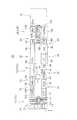
図1に、本発明の基板処理装置を適用できる一構成例としての塗布現像処理システムを示す。この塗布現像処理システム10は、クリーンルーム内に設置され、たとえばLCD基板を被処理基板とし、LCD製造プロセスにおいてフォトリソグラフィー工程の中の洗浄、レジスト塗布、プリベーク、現像およびポストベーク等の一連の処理を行うものである。露光処理はこの処理システムに隣接して設置される外部の露光装置12で行われる。
FIG. 1 shows a coating and developing treatment system as one configuration example to which the substrate processing apparatus of the present invention can be applied. This coating /
この塗布現像処理システム10は、中心部に横長のプロセスステーション(P /S)16を配置し、その長手方向(X方向)両端部にカセットステーション(C/S)14とインタフェースステーション(I/F)18とを配置している。
In this coating and developing
カセットステーション(C/S)14は、システム10のカセット搬入出ポートであり、角型のガラス基板Gを多段に積み重ねるようにして複数枚収容可能なカセットCを水平方向たとえばY方向に4個まで並べて載置可能なカセットステージ20と、このステージ20上のカセットCに対して基板Gの出し入れを行う搬送機構22とを備えている。搬送機構22は、基板Gを保持できる手段たとえば搬送アーム22aを有し、X,Y,Z,θの4軸で動作可能であり、隣接するプロセスステーション(P/S)16側と基板Gの受け渡しを行えるようになっている。
The cassette station (C / S) 14 is a cassette loading / unloading port of the
プロセスステーション(P/S)16は、システム長手方向(X方向)に延在する平行かつ逆向きの一対のラインA,Bに各処理部をプロセスフローまたは工程の順に配置している。より詳細には、カセットステーション(C/S)14側からインタフェースステーション(I/F)18側へ向う上流部のプロセスラインAには、洗浄プロセス部24と、第1の熱的処理部26と、塗布プロセス部28と、第2の熱的処理部30とを横一列に配置している。一方、インタフェースステーション(I/F)18側からカセットステーション(C/S)14側へ向う下流部のプロセスラインBには、第2の熱的処理部30と、現像プロセス部32と、脱色プロセス部34と、第3の熱的処理部36とを横一列に配置している。このライン形態では、第2の熱的処理部30が、上流側のプロセスラインAの最後尾に位置するとともに下流側のプロセスラインBの先頭に位置しており、両ラインA,B間に跨っている。
In the process station (P / S) 16, the processing units are arranged in the order of the process flow or process on a pair of parallel and opposite lines A and B extending in the system longitudinal direction (X direction). More specifically, the upstream process line A from the cassette station (C / S) 14 side to the interface station (I / F) 18 side includes a
両プロセスラインA,Bの間には補助搬送空間38が設けられており、基板Gを1枚単位で水平に載置可能なシャトル40が図示しない駆動機構によってライン方向(X方向)で双方向に移動できるようになっている。
An
上流部のプロセスラインAにおいて、洗浄プロセス部24は、スクラバ洗浄ユニット(SCR)42を含んでおり、このスクラバ洗浄ユニット(SCR)42内のカセットステーション(C/S)10と隣接する場所にエキシマUV照射ユニット(e−UV)41を配置している。スクラバ洗浄ユニット(SCR)42内の洗浄部は、基板Gをコロ搬送またはベルト搬送により水平姿勢でラインA方向に搬送しながら基板Gの上面(被処理面)にブラッシング洗浄やブロー洗浄を施すようになっている。
In the upstream process line A, the
洗浄プロセス部24の下流側に隣接する第1の熱的処理部26は、プロセスラインAに沿って中心部に縦型の搬送機構46を設け、その前後両側に複数の枚葉式オーブンユニットを基板受け渡し用のパスユニットと一緒に多段に積層配置してなる多段ユニット部またはオーブンタワー(TB)44,48を設けている。
The first
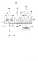
たとえば、図2に示すように、上流側のオーブンタワー(TB)44には、基板搬入用のパスユニット(PASSL)50、脱水ベーク用の加熱ユニット(DHP)52,54およびアドヒージョンユニット(AD)56が下から順に積み重ねられる。ここで、パスユニット(PASSL)50は、スクラバ洗浄ユニット(SCR)42からの洗浄処理の済んだ基板Gを第1の熱的処理部26内に搬入するためのスペースを提供する。下流側のオーブンタワー(TB)48には、基板搬出用のパスユニット(PASSR)60、基板温度調整用の冷却ユニット(CL)62,64およびアドヒージョンユニット(AD)66が下から順に積み重ねられる。ここで、パスユニット(PASSR)60は、第1の熱的処理部26で所要の熱処理の済んだ基板Gを下流側の塗布プロセス部28へ搬出するためのスペースを提供する。
For example, as shown in FIG. 2, an upstream oven tower (TB) 44 includes a substrate carrying pass unit (PASS L ) 50, dehydrating baking heating units (DHP) 52 and 54, and an adhesion unit. (AD) 56 are stacked in order from the bottom. Here, the pass unit (PASS L ) 50 provides a space for carrying the substrate G after the cleaning process from the scrubber cleaning unit (SCR) 42 into the first
図2において、搬送機構46は、鉛直方向に延在するガイドレール68に沿って昇降移動可能な昇降搬送体70と、この昇降搬送体70上でθ方向に回転または旋回可能な旋回搬送体72と、この旋回搬送体72上で基板Gを支持しながら前後方向に進退または伸縮可能な搬送アームまたはピンセット74とを有している。昇降搬送体70を昇降駆動するための駆動部76が垂直ガイドレール68の基端側に設けられ、旋回搬送体72を旋回駆動するための駆動部78が昇降搬送体70に取り付けられ、搬送アーム74を進退駆動するための駆動部80が回転搬送体72に取り付けられている。各駆動部76,78,80はたとえば電気モータ等で構成されてよい。
In FIG. 2, the
上記のように構成された搬送機構46は、高速に昇降ないし旋回運動して両隣のオーブンタワー(TB)44,48の中の任意のユニットにアクセス可能であり、補助搬送空間38側のシャトル40とも基板Gを受け渡しできるようになっている。
The
第1の熱的処理部26の下流側に隣接する塗布プロセス部28は、図1に示すように、レジスト塗布ユニット(CT)82と減圧乾燥ユニット(VD)84とをプロセスラインAに沿って一列に配置している。塗布プロセス部28内の構成は後に詳細に説明する。
The
塗布プロセス部28の下流側に隣接する第2の熱的処理部30は、上記第1の熱的処理部26と同様の構成を有しており、両プロセスラインA,Bの間に縦型の搬送機構90を設け、プロセスラインA側(最後尾)に一方のオーブンタワー(TB)88を設け、プロセスラインB側(先頭)に他方のオーブンタワー(TB)92を設けている。
The second
図示省略するが、たとえば、プロセスラインA側のオーブンタワー(TB)88には、最下段に基板搬入用のパスユニット(PASSL)が配置され、その上にプリベーク用の加熱ユニット(PREBAKE)がたとえば3段積みに重ねられてよい。また、プロセスラインB側のオーブンタワー(TB)92には、最下段に基板搬出用のパスユニット(PASSR)が配置され、その上に基板温度調整用の冷却ユニット(COL)がたとえば1段重ねられ、その上にプリベーク用の加熱ユニット(PREBAKE)がたとえば2段積みに重ねられてよい。 Although not shown, for example, in the oven tower (TB) 88 on the process line A side, a substrate loading pass unit (PASS L ) is disposed at the bottom, and a pre-baking heating unit (PREBAKE) is disposed thereon. For example, they may be stacked in three stages. Further, in the oven tower (TB) 92 on the process line B side, a pass unit (PASS R ) for carrying out the substrate is disposed at the lowest stage, and a cooling unit (COL) for adjusting the substrate temperature is provided thereon, for example, one stage. The heating unit (PREBAKE) for pre-baking may be stacked thereon, for example, in a two-stage stack.
第2の熱的処理部30における搬送機構90は、両オーブンタワー(TB)88,92のそれぞれのパスユニット(PASSL),(PASSR)を介して塗布プロセス部28および現像プロセス部32と基板Gを1枚単位で受け渡しできるだけでなく、補助搬送空間38内のシャトル40や後述するインタフェースステーション(I/F)18とも基板Gを1枚単位で受け渡しできるようになっている。
The
下流部のプロセスラインBにおいて、現像プロセス部32は、基板Gを水平姿勢で搬送しながら一連の現像処理工程を行う、いわゆる平流し方式の現像ユニット(DEV)94を含んでいる。
In the downstream process line B, the
現像プロセス部32の下流側には脱色プロセス部34を挟んで第3の熱的処理部36が配置される。脱色プロセス部34は、基板Gの被処理面にi線(波長365nm)を照射して脱色処理を行うためのi線UV照射ユニット(i−UV)96を備えている。
A third
第3の熱的処理部36は、上記第1の熱的処理部26や第2の熱的処理部30と同様の構成を有しており、プロセスラインBに沿って縦型の搬送機構100とその前後両側に一対のオーブンタワー(TB)98,102を設けている。
The third
図示省略するが、たとえば、上流側のオーブンタワー(TB)98には、最下段に基板搬入用のパスユニット(PASSL)が置かれ、その上にポストベーキング用の加熱ユニット(POBAKE)がたとえば3段積みに重ねられてよい。また、下流側のオーブンタワー(TB)102には、最下段にポストベーキング・ユニット(POBAKE)が置かれ、その上に基板搬出および冷却用のパス・クーリングユニット(PASSR・COL)が1段重ねられ、その上にポストベーキング用の加熱ユニット(POBAKE)が2段積みに重ねられてよい。 Although not shown, for example, in the upstream oven tower (TB) 98, a pass unit (PASS L ) for carrying a substrate is placed at the lowest stage, and a heating unit (POBAKE) for post-baking is placed thereon, for example. May be stacked in three stacks. Further, in the oven tower (TB) 102 on the downstream side, a post baking unit (POBAKE) is placed at the lowermost stage, and a pass cooling unit (PASS R · COL) for carrying out and cooling the substrate is placed on the post baking unit (POSBAKE). The heating unit (POBAKE) for post-baking may be stacked in two layers.
第3の熱的処理部36における搬送機構100は、両多段ユニット部(TB)98,102のパスユニット(PASSL)およびパス・クーリングユニット(PASSR・COL)を介してそれぞれi線UV照射ユニット(i−UV)96およびカセットステーション(C/S)14と基板Gを1枚単位で受け渡しできるだけでなく、補助搬送空間38内のシャトル40とも基板Gを1枚単位で受け渡しできるようになっている。
The
インタフェースステーション(I/F)18は、隣接する露光装置12と基板Gのやりとりを行うための搬送装置104を有し、その周囲にバッファ・ステージ(BUF)106、エクステンション・クーリングステージ(EXT・COL)108および周辺装置110を配置している。バッファ・ステージ(BUF)106には定置型のバッファカセット(図示せず)が置かれる。エクステンション・クーリングステージ(EXT・COL)108は、冷却機能を備えた基板受け渡し用のステージであり、プロセスステーション(P/S)16側と基板Gをやりとりする際に用いられる。周辺装置110は、たとえばタイトラー(TITLER)と周辺露光装置(EE)とを上下に積み重ねた構成であってよい。搬送装置104は、基板Gを保持できる手段たとえば搬送アーム104aを有し、隣接する露光装置12や各ユニット(BUF)106、(EXT・COL)108、(TITLER/EE)110と基板Gの受け渡しを行えるようになっている。
The interface station (I / F) 18 includes a
図3に、この塗布現像処理システムにおける処理の手順を示す。先ず、カセットステーション(C/S)14において、搬送機構22が、ステージ20上のいずれかのカセットCの中から1つの基板Gを取り出し、プロセスステーション(P/S)16の洗浄プロセス部24のエキシマUV照射ユニット(e−UV)41に搬入する(ステップS1)。
FIG. 3 shows a processing procedure in this coating and developing processing system. First, in the cassette station (C / S) 14, the
エキシマUV照射ユニット(e−UV)41内で基板Gは紫外線照射による乾式洗浄を施される(ステップS2)。この紫外線洗浄では主として基板表面の有機物が除去される。紫外線洗浄の終了後に、基板Gは、カセットステーション(C/S)14の搬送機構22によって洗浄プロセス部24のスクラバ洗浄ユニット(SCR)42へ移される。
Excimer UV irradiation unit (e-UV) substrate G in the 41 is subjected to dry cleaning by UV irradiation (step S 2). This UV cleaning mainly removes organic substances on the substrate surface. After completion of the ultraviolet cleaning, the substrate G is moved to the scrubber cleaning unit (SCR) 42 of the
スクラバ洗浄ユニット(SCR)42では、上記したように基板Gをコロ搬送またはベルト搬送により水平姿勢でプロセスラインA方向に平流しで搬送しながら基板Gの上面(被処理面)にブラッシング洗浄やブロー洗浄を施すことにより、基板表面から粒子状の汚れを除去する(ステップS3)。そして、洗浄後も基板Gを平流しで搬送しながらリンス処理を施し、最後にエアーナイフ等を用いて基板Gを乾燥させる。 In the scrubber cleaning unit (SCR) 42, as described above, the substrate G is brushed or blown onto the upper surface (surface to be processed) of the substrate G while being transported in a horizontal position in the horizontal direction by roller transport or belt transport. By performing cleaning, particulate dirt is removed from the substrate surface (step S 3 ). After the cleaning, the substrate G is rinsed while being conveyed in a flat flow, and finally the substrate G is dried using an air knife or the like.
スクラバ洗浄ユニット(SCR)42内で洗浄処理の済んだ基板Gは、第1の熱的処理部26の上流側オーブンタワー(TB)44内のパスユニット(PASSL)50に平流しで搬入される。
The substrate G that has been cleaned in the scrubber cleaning unit (SCR) 42 is carried into the pass unit (PASS L ) 50 in the upstream oven tower (TB) 44 of the first
第1の熱的処理部26において、基板Gは搬送機構46により所定のシーケンスで所定のオーブンユニットに順次移送される。たとえば、基板Gは、最初にパスユニット(PASSL)50から加熱ユニット(DHP)52,54の1つに移され、そこで脱水処理を受ける(ステップS4)。次に、基板Gは、冷却ユニット(COL)62,64の1つに移され、そこで一定の基板温度まで冷却される(ステップS5)。しかる後、基板Gはアドヒージョンユニット(AD)56に移され、そこで疎水化処理を受ける(ステップS6)。この疎水化処理の終了後に、基板Gは冷却ユニット(COL)62,64の1つで一定の基板温度まで冷却される(ステップS7)。最後に、基板Gは下流側オーブンタワー(TB)48内のパスユニット(PASSR)60に移される。
In the first
このように、第1の熱的処理部26内では、基板Gが、搬送機構46を介して上流側の多段オーブンタワー(TB)44と下流側のオーブンタワー(TB)48との間で任意に行き来できるようになっている。なお、第2および第3の熱的処理部30,36でも同様の基板搬送動作が行なわれる。
As described above, in the first
第1の熱的処理部26で上記のような一連の熱的または熱系の処理を受けた基板Gは、下流側オーブンタワー(TB)48内のパスユニット(PASSR)60から塗布プロセス部28のレジスト塗布ユニット(CT)82へ移される。
The substrate G that has undergone a series of thermal or thermal processing as described above in the first
レジスト塗布ユニット(CT)82において、基板Gは、後述するように長尺型のレジストノズルを用いるスピンレス法により基板上面(被処理面)にレジスト液を塗布される。次いで、基板Gは、下流側隣の減圧乾燥ユニット(VD)84で減圧による乾燥処理を受ける(ステップS8)。 In the resist coating unit (CT) 82, the substrate G is coated with a resist solution on the upper surface (surface to be processed) by a spinless method using a long resist nozzle as will be described later. Next, the substrate G is subjected to a drying process by a reduced pressure drying unit (VD) 84 adjacent to the downstream side (step S 8 ).
上記のようなレジスト塗布処理を受けた基板Gは、減圧乾燥ユニット(VD)84から隣の第2の熱的処理部30の上流側オーブンタワー(TB)88内のパスユニット(PASSL)に搬入される。
The substrate G subjected to the resist coating process as described above is transferred from the reduced pressure drying unit (VD) 84 to the pass unit (PASS L ) in the upstream oven tower (TB) 88 of the adjacent second
第2の熱的処理部30内で、基板Gは、搬送機構90により所定のシーケンスで所定のユニットに順次移送される。たとえば、基板Gは、最初にパスユニット(PASSL)から加熱ユニット(PREBAKE)の1つに移され、そこでプリベーキングの加熱処理を受ける(ステップS9)。次に、基板Gは、冷却ユニット(COL)の1つに移され、そこで一定の基板温度まで冷却される(ステップS10)。しかる後、基板Gは下流側オーブンタワー(TB)92側のパスユニット(PASSR)を経由して、あるいは経由せずにインタフェースステーション(I/F)18側のエクステンション・クーリングステージ(EXT・COL)108へ受け渡される。
Within the second
インタフェースステーション(I/F)18において、基板Gは、エクステンション・クーリングステージ(EXT・COL)108から周辺装置110の周辺露光装置(EE)に搬入され、そこで基板Gの周辺部に付着するレジストを現像時に除去するための露光を受けた後に、隣の露光装置12へ送られる(ステップS11)。
In the interface station (I / F) 18, the substrate G is transferred from the extension / cooling stage (EXT / COL) 108 to the peripheral exposure device (EE) of the
露光装置12では基板G上のレジストに所定の回路パターンが露光される。そして、パターン露光を終えた基板Gは、露光装置12からインタフェースステーション(I/F)18に戻されると(ステップS11)、先ず周辺装置110のタイトラー(TITLER)に搬入され、そこで基板上の所定の部位に所定の情報が記される(ステップS12)。しかる後、基板Gはエクステンション・クーリングステージ(EXT・COL)108に戻される。インタフェースステーション(I/F)18における基板Gの搬送および露光装置12との基板Gのやりとりは搬送装置104によって行われる。
In the
プロセスステーション(P/S)16では、第2の熱的処理部30において搬送機構90がエクステンション・クーリングステージ(EXT・COL)108より露光済の基板Gを受け取り、プロセスラインB側のオーブンタワー(TB)92内のパスユニット(PASSR)を介して現像プロセス部32へ受け渡す。
In the process station (P / S) 16, the
現像プロセス部32では、該オーブンタワー(TB)92内のパスユニット(PASSR)から受け取った基板Gを現像ユニット(DEV)94に搬入する。現像ユニット(DEV)94において基板GはプロセスラインBの下流に向って平流し方式で搬送され、その搬送中に現像、リンス、乾燥の一連の現像処理工程が行われる(ステップS13)。
In the
現像プロセス部32で現像処理を受けた基板Gは下流側隣の脱色プロセス部34へ平流しで搬入され、そこでi線照射による脱色処理を受ける(ステップS14)。脱色処理の済んだ基板Gは、第3の熱的処理部36の上流側オーブンタワー(TB)98内のパスユニット(PASSL)に搬入される。
The substrate G subjected to the development process in the
第3の熱的処理部36において、基板Gは、最初に該パスユニット(PASSL)から加熱ユニット(POBAKE)の1つに移され、そこでポストベーキングの加熱処理を受ける(ステップS15)。次に、基板Gは、下流側オーブンタワー(TB)102内のパスクーリング・ユニット(PASSR・COL)に移され、そこで所定の基板温度に冷却される(ステップS16)。第3の熱的処理部36における基板Gの搬送は搬送機構100によって行われる。
In the third
カセットステーション(C/S)14側では、搬送機構22が、第3の熱的処理部36のパスクーリング・ユニット(PASSR・COL)から塗布現像処理の全工程を終えた基板Gを受け取り、受け取った基板Gをステージ20上のいずれかのカセットCに収容する(ステップS1)。
On the cassette station (C / S) 14 side, the
この塗布現像処理システム10においては、塗布プロセス部28のレジスト塗布ユニット(CT)82に本発明を適用することができる。以下、図4〜図17を参照して本発明をレジスト塗布ユニット(CT)82に適用した実施形態を説明する。
In this coating and developing
図4に示すように、塗布プロセス部28は、支持台112の上にレジスト塗布ユニット(CT)82と減圧乾燥ユニット(VD)84とをX方向に(プロセスラインAに沿って)一列に配置している。X方向に延びる一対のガイドレール114,114が支持台112の両端部に平行に敷設され、両ガイドレール114,114に案内されて移動する一組または複数組の搬送アーム116,116により、レジスト塗布ユニット(CT)82から減圧乾燥ユニット(VD)84へ基板Gを転送できるようになっている。さらに、搬送アーム116,116により、隣接するオーブンタワー(TB)48のパスユニット(PASSR)から塗布処理前の基板Gをレジスト塗布ユニット(CT)82に搬入し、減圧乾燥ユニット(VD)84から隣接するオーブンタワー(TB)88のパスユニット(PASSL)へ塗布処理済みの基板Gを搬出するようになっている。
As shown in FIG. 4, the
レジスト塗布ユニット(CT)82は、基板Gを水平に載置して保持するためのステージ118と、このステージ118上に載置される基板Gの上面(被処理面)に長尺型のレジストノズル120を用いてスピンレス法でレジスト液を塗布するための塗布処理部122と、塗布処理を行わない間にレジストノズル120のレジスト液吐出機能を回復して次に備えるためのノズル待機部124等を有する。レジスト塗布ユニット(CT)82内の各部の構成および作用は図5〜図17を参照して後に詳述する。
The resist coating unit (CT) 82 includes a
減圧乾燥ユニット(VD)84は、上面が開口しているトレーまたは底浅容器型の下部チャンバ126と、この下部チャンバ126の上面に気密に密着または嵌合可能に構成された蓋状の上部チャンバ(図示せず)とを有している。下部チャンバ126はほぼ四角形で、中心部には基板Gを水平に載置して支持するためのステージ128が配設され、底面の四隅には排気口130が設けられている。各排気口130は排気管(図示せず)を介して真空ポンプ(図示せず)に通じている。下部チャンバ126に上部チャンバを被せた状態で、両チャンバ内の密閉された処理空間を該真空ポンプにより所定の真空度まで減圧できるようになっている。
The vacuum drying unit (VD) 84 includes a tray or shallow container type
図5に、レジスト塗布ユニット(CT)82における塗布処理部122の構成を示す。塗布処理部122は、レジストノズル120を含むレジスト液供給部132と、塗布処理時にレジストノズル120をステージ118の上方でX方向に水平移動させる水平移動機構134とを有する。レジスト液供給部132において、レジストノズル120は、ステージ118上の基板Gを一端から他端までカバーできる長さでY方向に延びる長尺型のノズルであり、レジスト液供給源(図示せず)からのレジスト液供給管136に接続されている。水平移動機構134は、レジストノズル120を水平に支持する逆さコ字状または門形の支持体138と、この支持体138をX方向で双方向に直進移動させる直進駆動部140とを有する。この直進駆動部140は、たとえばガイド付きのリニアモータ機構またはボールねじ機構で構成されてよい。また、レジストノズル120の高さ位置を変更または調節するためのガイド付きの昇降機構135が、たとえば支持体138とレジストノズル120とを接続するジョイント部142に設けられている。昇降機構135がレジストノズル120の高さ位置を調節することで、レジストノズル120の下端または吐出口120aとステージ118上の基板Gの上面(被処理面)との間の距離間隔つまりギャップの大きさを任意に設定または調整することができる。
FIG. 5 shows a configuration of the
この実施形態では、レジストノズル120の両端部に一対のジョイント部142L,142Rを接続し、レジストノズル120の高さ調整を左右両端で独立的に制御できるようになっている。ここで、塗布処理時の進行方向を基準として、レジストノズル120の左側端部に接続されるジョイント部142Lを左ジョイント部とし、反対側(レジストノズル120の右側端部)に接続されるジョイント部142Rを右ジョイント部とする。昇降機構135は、左ジョイント部142L側の左Z軸機構135Lと、右ジョイント部142R側の右Z軸機構135Rとで構成される。左右の両Z軸機構135L,135Rはそれぞれ独立した案内部と駆動部とを有している。
In this embodiment, a pair of
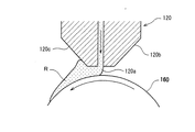
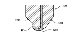
レジストノズル120は、たとえばステンレス鋼等の対錆性と加工性に優れた金属からなり、下端の吐出口120aに向って先細りのテーパ面120b,120cを有している。ここで、一方のテーパ面120bは塗布処理時の進行方向で前方を向く前面であり、他方のテーパ面120cは塗布処理時の進行方向で後方を向く背面である。吐出口120aは、ノズル長手方向に延びるスリット型であってよく、あるいは微細径の吐出孔をノズル長手方向に一定ピッチで配列した多孔型であってもよい。
The resist
図6に、ノズル待機部124の構成を示す。図示のように、ノズル待機部124は、洗浄部144と溶剤雰囲気室146とプライミング処理部148とをX方向で横一列に配置している。この中で、プライミング処理部148がステージ118に最も近い場所に位置している。水平移動機構134(図5)の直進駆動部140がノズル待機部124まで延びており(図4)、レジストノズル120をノズル待機部124の各部(144,146,148)に移送できるようになっている。
FIG. 6 shows the configuration of the
洗浄部144は、ユニット内の所定位置に配置されたレジストノズル120の下を長手方向(Y方向)に移動またはスキャンするノズル洗浄ヘッド150を有している。このノズル洗浄ヘッド150には、レジストノズル120の下端部および吐出口120aに向けて洗浄液(たとえばシンナー)および乾燥用のガス(たとえばN2ガス)をそれぞれ噴き付ける洗浄ノズル152およびガスノズル154が搭載されるとともに、レジストノズル120に当たって落下した洗浄液をバキューム力で受け集めて回収するドレイン部156が設けられている。
The
溶剤雰囲気室146は、レジストノズル120の全長をカバーする長さでY方向に延びており、室内には溶剤(たとえばシンナー)が入っている。溶剤雰囲気室146の上面には、長手方向(Y方向)に延びるスリット状の開口158aを設けた断面V状の蓋体158が取り付けられている。レジストノズル120のノズル部を蓋体158に上方から合わせると、吐出口120aとノズル下端部だけが開口158aを介して室内に立ち篭もる溶剤の蒸気に曝されるようになっている。
The
プライミング処理部148は、レジストノズル120の全長をカバーする長さでY方向に延びる円筒状または円柱状のプライミングローラ160を溶剤浴室161の中に配置している。溶剤浴室161内には、プライミングローラ160の下部が浸かる程度の液面レベルで溶剤または洗浄液(たとえばシンナー)が収容されている。プライミングローラ160は回転機構162によって回転駆動されるようになっている。また、溶剤浴室162内の洗浄液よりも上方の位置でプライミングローラ160の外周面と擦接するワイパ164が設けられている。プライミング処理部148の作用は後述する。
The
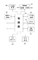
図7に、レジスト塗布ユニット(CT)82内の制御系の構成を示す。制御部166は、メインコントローラまたは局所コントローラとして、ユニット(CT)82内の各部、たとえば水平移動機構134、昇降機構135(左Z軸機構135L,右Z軸機構135R)、レジスト液供給部132、ノズル洗浄ヘッド150、回転機構162、基板厚み測定部168、リフトピン・アクチエータ170および吸着固定部172を制御する。ここで、基板厚み測定部168は、基板の厚み(板厚)にばらつき(個体差)がある場合に有用であり、図示省略するが、塗布処理に先立ってステージ118上の基板Gの厚みを測定する。基板厚み測定法は、触針を用いるダイヤルゲージ式あるいはレーザ光を用いる非接触の光学式等であってよい。リフトピン・アクチエータ170は、後述するように、基板の搬入/搬出時にステージ118の上で基板Gを水平姿勢で上げ下げするためのリフトピン174(図8、図12)を昇降駆動する。また、吸着固定部172は、後述するように、ステージ118上に基板Gを載置している間にステージ118の上面に設けた吸引口176(図8、図12)を通じて基板Gをバキューム力で吸着固定する機構である。
FIG. 7 shows the configuration of the control system in the resist coating unit (CT) 82. The
次に、このレジスト塗布ユニット(CT)82における作用を説明する。 Next, the operation of the resist coating unit (CT) 82 will be described.
ユニット(CT)82に新たな基板Gが搬入されるまでの間、レジストノズル120はノズル待機部124の溶剤雰囲気室146で待機している。上記のように、第1の熱的処理部26(図1)で所定の熱処理を受けた基板Gが下流側オーブンタワー(TB)48内のパスユニット(PASSR)60(図2)からレジスト塗布ユニット(CT)82に搬入される。こうして新規の基板Gが搬入されると、この基板Gをステージ118上に載置するためのローディング動作が行われる。詳細には、搬送アーム116,116が基板Gをステージ118の真上まで移送し、図8に示すように、ステージ118の中から複数本のリフトピン174が上昇または突出して基板Gを受け取る。次いで、リフトピン174が基板Gを水平に担持したままステージ118の中へ下降または退避することにより、基板Gがステージ118の上面に移載される。リフトピン174は、水平駆動板178を介してシリンダ等のリフトピン・アクチエータ170(図7)に結合されており、リフトピン・アクチエータ170の昇降駆動によって上記のようなローディングのための昇降動作を行う。基板Gがステージ118上に載置されると、吸着固定部172で開閉弁180がオン(開状態)に切り換えられて、真空源(図示せず)からのバキューム力が負圧流路を介してステージ上面の吸引口176に与えられる(図8)。これにより、ステージ118上で基板Gは吸引口176より真空吸着力を受けて固定される。
Until a new substrate G is carried into the unit (CT) 82, the resist
上記のようにステージ118上で基板Gのローディングが行われるのと並行して、ノズル待機部124ではレジストノズル120が溶剤雰囲気室146から隣のプライミング処理部148へ移され、そこでプライミング処理が行われる。
In parallel with the loading of the substrate G on the
このプライミング処理では、吐出口120aがプライミングローラ160の頂上部と微小なギャップを隔てて対向する位置までレジストノズル120を近接させ、そこでレジストノズル120にレジスト液Rを吐出させ、これと同時にプライミングローラ160を回転機構162により一定方向(図8では反時計回り)に回転させる。そうすると、図9に拡大して示すように、レジストノズル120の吐出口120aより出たレジスト液Rがノズル背面120c側に回り込んでからプライミングローラ160の外周面に巻き取られる。レジスト液を巻き取ったプライミングローラ160の外周面は、直後に溶剤の浴に入ってレジスト液Rを洗い落とす。そして、溶剤浴から上がったプライミングローラ160の外周面は、ワイパ164により液を拭い取られ、清浄な面を回復してから再びレジストノズル120の吐出口120aの下を通過しそこでレジスト液を受け取る。なお、レジストノズル120の吐出口とプライミングローラ160との間に形成されるギャップの大きさ(距離)は、塗布処理時にレジストノズル120の吐出口とステージ118上の基板Gとの間に形成されるギャップと同一または近似した値(たとえば40〜150μm)に設定されてよい。
In this priming process, the resist
このプライミング処理に際しては、レジストノズル120がレジスト液吐出動作を開始してから一定の遅延時間(たとえば1秒)を置いてプライミングローラ160の回転動作を開始させるのが好ましく、この時間差方式によってレジスト液Rをレジストノズル120のテーパ背面120c側へ十全に回り込ませることができる。
In this priming process, it is preferable to start the rotation operation of the priming
こうして、プライミング処理を終えた後も、図10に示すように、レジストノズル120の下端部に、特に吐出口120aからテーパ背面120cにかけてレジスト液の液膜RFが残る。理想的には、図11Aに示すように、レジストノズル120の長手方向で一端から他端まで液膜RFがまっすぐ均一に形成される。しかしながら、実際には、液膜形成が安定せずにレジストノズル120の長手方向で不均一になることがあり、たとえば図11Bに示すように液膜の少ない箇所が発生することがある。
Thus, even after the priming process is completed, as shown in FIG. 10, a liquid film RF of the resist solution remains at the lower end portion of the resist
上記のようなプライミング処理を受けたレジストノズル120は、図12に示すように、昇降機構135および水平移動機構134によってプライミング処理部148から塗布処理部122内に移送され、ステージ118上に設定されている塗布開始位置の上方でいったん止まる。直後に、レジストノズル120は、図13に示すように塗布開始位置に向かって垂直下方に下ろされる。塗布開始位置でレジストノズル120はステージ118上の基板Gと所定距離Dのギャップを隔てて対向することになる。
The resist
この実施形態では、制御部166が昇降機構135(左Z軸機構135L,右Z軸機構135R)を通じてレジストノズル120を左端部と右端部との間で塗布開始位置の高さ位置まで下りるタイミングをずらす(時間差をもたせる)。より詳細には、図14Aに示すように、レジストノズル120の一方の端部たとえば右端部を先に塗布開始位置の高さ位置まで下ろす。これにより、レジストノズル120の下端部に付いている液膜RFは最初に右端部から基板Gに付着する。その後少し遅れてレジストノズル120の左端部を塗布開始位置の高さ位置まで下ろす。
In this embodiment, the timing at which the
そうすると、図14Bおよび図14Cに示すように、レジストノズル120下端部の液膜RFは、レジストノズル120の右端部から左端部に向かって連続的に基板Gに着液(付着)する。つまり、レジストノズル120の右端部で液膜RFが基板Gに付着したことによって生じた基板上のぬれ(wet)が方向性をもって(ノズル左端部に向かって)広がり、途中でレジストノズル120側に液膜の少ない箇所があっても、基板G上のぬれの勢いでその付近でも着液し、レジストノズル120と基板G間のギャップを塞ぐ液膜(ビード)が他方の端部まで連続的につながって延びる。
Then, as shown in FIGS. 14B and 14C, the liquid film RF at the lower end portion of the resist
こうして、図14Cおよび図15に示すように、塗布開始位置において、水平姿勢のレジストノズル120の吐出口120aとステージ118上の基板Gとの間に設定距離Dのギャップが形成されるとともに、ノズル長手方向に一端(右端)から他端(左端)まで隙間なく液膜RFがギャップを塞いだ状態となる。この状態で塗布処理が開始される。
Thus, as shown in FIGS. 14C and 15, a gap of a set distance D is formed between the
塗布処理では、制御部166の制御の下で、レジスト液供給部132が作動してレジストノズル120がレジスト液Rを基板G上に吐出すると同時に、水平移動機構134が作動してレジストノズル120が一定の速度でX方向の所定の向き(ノズル待機部124から離れる向き)に水平移動する。塗布処理の開始直後、レジストノズル120の吐出口より帯状に出たレジスト液がスムースにノズル背面下部に回り込んでノズル長手方向に一直線に延びる凸面状のメニスカスを形成する。塗布処理中も、図17に示すように、このメニスカスの頂上ライン(ウエットライン)WLは水平一直線に安定する。これによって、レジスト塗布膜RM上に筋状の塗布ムラの生じる可能性が大幅に低減する。
In the coating process, under the control of the
上記のように、この実施形態のレジスト塗布ユニット(CT)82においては、塗布処理に先立つプライミング処理でレジストノズル120の下端部に付けた液膜RFがノズル長手方向で不均一であっても、レジストノズル120をステージ118上に設定された塗布開始位置まで下降させる際に、レジストノズル120の左端部と右端部との間で塗布開始位置の高さ位置まで下りるタイミングをずらすことにより、レジストノズル120から所望距離のギャップを介しての基板Gへの着液をノズル長手方向で満遍なく確実に成し遂げることができる。
As described above, in the resist coating unit (CT) 82 of this embodiment, even if the liquid film RF attached to the lower end portion of the resist
以上、好適な実施形態について説明したが、本発明の技術的思想の範囲内で種々の変形が可能である。特に、レジストノズル120を昇降させる昇降機構135において種々の変形が可能であり、たとえばレジストノズルを支持体に取り付け、この支持体の左右端部を個別の昇降案内部ないし昇降駆動部に接続する構成とすることも可能である。また、レジストノズルとステージ上の基板との位置関係は相対的なものであり、レジストノズルを固定してステージ上の基板を水平方向または鉛直方向で移動させる方式も可能である。上記した実施形態ではプライミングローラ160を用いてプライミング処理を行ったが、プライミングローラを使用しないプライミング処理も可能である。さらに、プライミング処理を行わないで塗布処理を開始するアプリケーションにも本発明は適用可能である。
The preferred embodiment has been described above, but various modifications can be made within the scope of the technical idea of the present invention. In particular, various modifications are possible in the elevating
上記した実施形態はLCD製造の塗布現像処理システムにおけるレジスト塗布装置に係るものであったが、本発明は被処理基板上に処理液を塗布する任意の処理装置やアプリケーションに適用可能である。したがって、本発明における処理液としては、レジスト液以外にも、たとえば層間絶縁材料、誘電体材料、配線材料等の塗布液も可能であり、現像液やリンス液等も可能である。本発明における被処理基板はLCD基板に限らず、他のフラットパネルディスプレイ用基板、半導体ウエハ、CD基板、ガラス基板、フォトマスク、プリント基板等も可能である。 The above-described embodiment relates to a resist coating apparatus in a coating / development processing system for LCD manufacturing. However, the present invention is applicable to any processing apparatus or application for coating a processing liquid on a substrate to be processed. Therefore, as the processing liquid in the present invention, in addition to the resist liquid, for example, a coating liquid such as an interlayer insulating material, a dielectric material, and a wiring material can be used, and a developing liquid or a rinsing liquid can also be used. The substrate to be processed in the present invention is not limited to an LCD substrate, and other flat panel display substrates, semiconductor wafers, CD substrates, glass substrates, photomasks, printed substrates, and the like are also possible.
10 プロセスステーション
28 塗布プロセス部
82 レジスト塗布ユニット(CT)
118 ステージ
120 レジストノズル
122 塗布処理部
124 ノズル待機部
132 レジスト液供給部
134 水平移動機構
135 昇降機構
135A 左Z軸機構
135B 右Z軸機構
148 プライミング洗浄部
160 プライミングローラ
166 制御部
174 リフトピン
176 吸引口
10
118
Claims (9)
塗布処理に先立ち前記塗布ノズルの下端部に処理液の液膜を付ける第1の工程と、
前記第1の工程の後に塗布開始位置で前記塗布ノズルを前記基板の上方から前記塗布ノズルの吐出口と前記基板との間に前記ギャップが形成される高さ位置まで下降させる第2の工程と
を有し、
前記第2の工程で、前記塗布ノズルの長手方向における一方の端部と他方の端部との間で前記高さ位置まで下りるタイミングを前記一方の端部よりも前記他方の端部が遅れるようにずらし、前記塗布ノズルの下端部の液膜を先に下りた前記一方の端部側から後に下りた前記他方の端部側に向かって連続的に前記基板に付着させる塗布方法。 A desired minute gap is set between the substantially horizontal substrate to be processed and the discharge port provided on the lower end surface of the long type coating nozzle, and the coating nozzle is relative to the horizontal direction substantially orthogonal to the nozzle longitudinal direction. An application method for applying the treatment liquid onto the substrate,
A first step of applying a liquid film of a treatment liquid to the lower end of the application nozzle prior to the application process;
A second step of lowering the application nozzle from above the substrate to a height position where the gap is formed between the discharge port of the application nozzle and the substrate at the application start position after the first step; Have
In the second step, the timing of descending to the height position between one end and the other end in the longitudinal direction of the application nozzle is set so that the other end is delayed from the one end. The coating method in which the liquid film at the lower end portion of the coating nozzle is continuously attached to the substrate from the one end side that descends first to the other end side that descends later.
前記基板上に処理液を塗布するために前記ステージ上の基板に対して上方から処理液を吐出する長尺型の塗布ノズルと、
前記塗布ノズルをその長手方向と直交する水平方向で前記ステージに対して相対的に移動させる水平移動部と、
前記塗布ノズルを鉛直方向で前記ステージに対して相対的に移動させる昇降部と、
前記塗布ノズルの長手方向における一方の端部と他方の端部との間で所定の高さ位置まで下りるタイミングを独立的に制御する下降制御部と
を有し、
前記下降制御部が、前記塗布ノズルの一方の端部と他方の端部との間で前記高さ位置まで下りるタイミングを前記一方の端部よりも前記他方の端部が遅れるようにずらすことを特徴とする塗布装置。 A stage for placing the substrate to be processed almost horizontally;
A long coating nozzle for discharging the processing liquid from above to the substrate on the stage in order to apply the processing liquid on the substrate;
A horizontal movement unit that moves the application nozzle relative to the stage in a horizontal direction perpendicular to the longitudinal direction;
An elevating unit that moves the application nozzle in a vertical direction relative to the stage;
Possess a descending controller to independently control the timing of descending to a predetermined height position between the one end in the longitudinal direction and the other end portion of the coating nozzle,
The lowering control unit shifts the timing of descending to the height position between one end and the other end of the application nozzle so that the other end is delayed from the one end. An applicator characterized .
前記塗布ノズルの一方の端部と他方の端部とにそれぞれ接続された第1および第2の昇降駆動部と、
前記塗布ノズルの一方の端部と他方の端部とを独立に案内する第1および2の案内部と
を有する請求項3に記載の塗布装置。 The elevating part is
First and second lifting and lowering drive units connected to one end and the other end of the application nozzle, respectively;
The coating apparatus according to claim 3 , further comprising: first and second guide portions that independently guide one end portion and the other end portion of the coating nozzle.
被処理基板をほぼ水平に載置するステージと、
前記基板上に処理液を塗布するために前記ステージ上の基板の上面に向けて処理液を吐出する長尺型の塗布ノズルと、
前記塗布ノズルをその長手方向と直交する水平方向で前記ステージに対して相対的に移動させる水平移動部と、
前記塗布ノズルを鉛直方向で前記ステージに対して相対的に移動させる昇降部と、
塗布処理に先立ち前記塗布ノズルの下端部に処理液の液膜を付けるプライミング処理部と、
前記塗布ノズルの長手方向における一方の端部を先に前記ステージ上の基板に対する塗布開始の高さ位置まで下ろして前記一方の端部の下端部に付いている処理液膜を基板に付着させ、その後、遅れて前記塗布ノズルの長手方向における他方の端部を塗布開始位置の高さ位置まで下ろすように制御する下降制御部と
を有する塗布装置。 A coating apparatus for applying a processing liquid to a substrate to be processed,
A stage for placing the substrate to be processed almost horizontally;
A long coating nozzle for discharging the processing liquid toward the upper surface of the substrate on the stage in order to apply the processing liquid on the substrate;
A horizontal movement unit that moves the application nozzle relative to the stage in a horizontal direction perpendicular to the longitudinal direction;
An elevating unit that moves the application nozzle in a vertical direction relative to the stage;
A priming processing unit that attaches a liquid film of a processing solution to the lower end of the coating nozzle prior to the coating process;
One end in the longitudinal direction of the coating nozzle is first lowered to the height position of the start of coating on the substrate on the stage, and the treatment liquid film attached to the lower end of the one end is attached to the substrate, And a lowering control unit that controls to lower the other end of the coating nozzle in the longitudinal direction to the height position of the coating start position after a delay.
被処理基板をほぼ水平に載置するステージと、
前記基板上に処理液を塗布するために前記ステージ上の基板の上面に向けて処理液を吐出する長尺型の塗布ノズルと、
前記塗布ノズルをその長手方向と直交する水平方向で前記ステージに対して相対的に移動させる水平移動部と、
前記塗布ノズルを鉛直方向で前記ステージに対して相対的に移動させる昇降部と、
塗布処理に先立ち前記塗布ノズルの下端部に処理液の液膜を付けるプライミング処理部と
を有し、
前記塗布ノズルの長手方向における一方の端部を先に前記ステージ上の基板に対する塗布開始の高さ位置まで下ろして前記一方の端部の下端部に付いている処理液膜を基板に付着させ、その後、遅れて前記塗布ノズルの長手方向における他方の端部を塗布開始位置の高さ位置まで下ろすことにより、前記着液により生じた基板上のぬれの勢いで前記塗布ノズルの長手方向における他方の端部に向かって広がり、前記塗布ノズルと前記基板間のギャップを隙間なく塞ぐ液膜を前記一方の端部から前記他方の端部まで連続的に形成する塗布装置。 A coating apparatus for applying a processing liquid to a substrate to be processed,
A stage for placing the substrate to be processed almost horizontally;
A long coating nozzle for discharging the processing liquid toward the upper surface of the substrate on the stage in order to apply the processing liquid on the substrate;
A horizontal movement unit that moves the application nozzle relative to the stage in a horizontal direction perpendicular to the longitudinal direction;
An elevating unit that moves the application nozzle in a vertical direction relative to the stage;
A priming treatment part that attaches a liquid film of a treatment liquid to the lower end part of the application nozzle prior to the application process,
Lowering one end portion in the longitudinal direction of the coating nozzle to the height position at which coating is started on the substrate on the stage first, and attaching the treatment liquid film attached to the lower end portion of the one end portion to the substrate; Thereafter, the other end portion in the longitudinal direction of the coating nozzle is lowered to the height position of the coating start position with a delay, and the other end in the longitudinal direction of the coating nozzle is caused by the momentum of wetting on the substrate caused by the liquid deposition. A coating apparatus that continuously forms a liquid film that spreads toward an end and closes a gap between the coating nozzle and the substrate without gap from the one end to the other end.
Priority Applications (1)
| Application Number | Priority Date | Filing Date | Title |
|---|---|---|---|
| JP2004257052A JP4498862B2 (en) | 2004-09-03 | 2004-09-03 | Coating method and coating apparatus |
Applications Claiming Priority (1)
| Application Number | Priority Date | Filing Date | Title |
|---|---|---|---|
| JP2004257052A JP4498862B2 (en) | 2004-09-03 | 2004-09-03 | Coating method and coating apparatus |
Publications (3)
| Publication Number | Publication Date |
|---|---|
| JP2006068673A JP2006068673A (en) | 2006-03-16 |
| JP2006068673A5 JP2006068673A5 (en) | 2006-11-02 |
| JP4498862B2 true JP4498862B2 (en) | 2010-07-07 |
Family
ID=36149824
Family Applications (1)
| Application Number | Title | Priority Date | Filing Date |
|---|---|---|---|
| JP2004257052A Expired - Fee Related JP4498862B2 (en) | 2004-09-03 | 2004-09-03 | Coating method and coating apparatus |
Country Status (1)
| Country | Link |
|---|---|
| JP (1) | JP4498862B2 (en) |
Families Citing this family (2)
| Publication number | Priority date | Publication date | Assignee | Title |
|---|---|---|---|---|
| JP5246857B2 (en) * | 2008-06-27 | 2013-07-24 | 東レエンジニアリング株式会社 | Coating device |
| JP2011013321A (en) * | 2009-06-30 | 2011-01-20 | Hoya Corp | Method of manufacturing photomask blank, method of manufacturing photomask, and coating device |
Citations (4)
| Publication number | Priority date | Publication date | Assignee | Title |
|---|---|---|---|---|
| JP2001276721A (en) * | 2000-03-29 | 2001-10-09 | Konica Corp | Coating method |
| JP2002500097A (en) * | 1998-01-09 | 2002-01-08 | エフエイスター、リミティド | System and method for cleaning and priming an extrusion head |
| JP2002001195A (en) * | 2000-06-19 | 2002-01-08 | Toray Ind Inc | Method and device for coating and method and device for manufacturing color filter |
| JP2004014607A (en) * | 2002-06-04 | 2004-01-15 | Dainippon Screen Mfg Co Ltd | Substrate processing apparatus |
Family Cites Families (3)
| Publication number | Priority date | Publication date | Assignee | Title |
|---|---|---|---|---|
| JPS61147234A (en) * | 1984-12-20 | 1986-07-04 | Fujitsu Ltd | Laminating method of polarizing plate |
| JPH06339665A (en) * | 1993-05-31 | 1994-12-13 | Yokohama Rubber Co Ltd:The | Method for coating wall surface |
| JP3245813B2 (en) * | 1996-11-27 | 2002-01-15 | 東京エレクトロン株式会社 | Coating film forming equipment |
-
2004
- 2004-09-03 JP JP2004257052A patent/JP4498862B2/en not_active Expired - Fee Related
Patent Citations (4)
| Publication number | Priority date | Publication date | Assignee | Title |
|---|---|---|---|---|
| JP2002500097A (en) * | 1998-01-09 | 2002-01-08 | エフエイスター、リミティド | System and method for cleaning and priming an extrusion head |
| JP2001276721A (en) * | 2000-03-29 | 2001-10-09 | Konica Corp | Coating method |
| JP2002001195A (en) * | 2000-06-19 | 2002-01-08 | Toray Ind Inc | Method and device for coating and method and device for manufacturing color filter |
| JP2004014607A (en) * | 2002-06-04 | 2004-01-15 | Dainippon Screen Mfg Co Ltd | Substrate processing apparatus |
Also Published As
| Publication number | Publication date |
|---|---|
| JP2006068673A (en) | 2006-03-16 |
Similar Documents
| Publication | Publication Date | Title |
|---|---|---|
| JP4398786B2 (en) | Coating method and coating apparatus | |
| JP5430697B2 (en) | Coating method and coating apparatus | |
| JP4980644B2 (en) | Coating method and coating apparatus | |
| KR101052949B1 (en) | Developing Processing Apparatus and Developing Processing Method | |
| JP3808741B2 (en) | Processing equipment | |
| US20090013927A1 (en) | Stage apparatus and coating treatment device | |
| JP4676359B2 (en) | Priming processing method and priming processing apparatus | |
| JP4451385B2 (en) | Coating processing apparatus and coating processing method | |
| JP4071183B2 (en) | Coating method and coating apparatus | |
| JP4429825B2 (en) | Substrate processing equipment | |
| JP4247890B2 (en) | Coating nozzle and coating device | |
| JP4516034B2 (en) | Coating method, coating apparatus, and coating program | |
| JP3741655B2 (en) | Liquid processing method and liquid processing apparatus | |
| KR20090031823A (en) | Normal pressure drying device, substrate processing apparatus and substrate processing method | |
| TW200537585A (en) | Coating film forming apparatus | |
| KR101067143B1 (en) | Coating film forming apparatus and coating film forming method | |
| JP5208093B2 (en) | Substrate processing apparatus, substrate processing method, and reduced pressure drying apparatus | |
| JP4422006B2 (en) | Processing apparatus, processing liquid supply method, and processing liquid supply program | |
| JP4804567B2 (en) | Substrate floating device | |
| KR101568050B1 (en) | Substrate processing apparatus | |
| JP2007173365A (en) | System and method for processing application drying | |
| JP4353530B2 (en) | Substrate processing method and substrate processing apparatus | |
| JP4498862B2 (en) | Coating method and coating apparatus | |
| KR20110066864A (en) | Substrate processing apparatus, substrate processing method and recording medium storing program for executing the substrate processing method | |
| JP4554303B2 (en) | Coating apparatus and coating method |
Legal Events
| Date | Code | Title | Description |
|---|---|---|---|
| A521 | Request for written amendment filed |
Free format text: JAPANESE INTERMEDIATE CODE: A523 Effective date: 20060907 |
|
| A621 | Written request for application examination |
Free format text: JAPANESE INTERMEDIATE CODE: A621 Effective date: 20060907 |
|
| A977 | Report on retrieval |
Free format text: JAPANESE INTERMEDIATE CODE: A971007 Effective date: 20090209 |
|
| A131 | Notification of reasons for refusal |
Free format text: JAPANESE INTERMEDIATE CODE: A131 Effective date: 20091201 |
|
| A521 | Request for written amendment filed |
Free format text: JAPANESE INTERMEDIATE CODE: A523 Effective date: 20100127 |
|
| TRDD | Decision of grant or rejection written | ||
| A01 | Written decision to grant a patent or to grant a registration (utility model) |
Free format text: JAPANESE INTERMEDIATE CODE: A01 Effective date: 20100413 |
|
| A01 | Written decision to grant a patent or to grant a registration (utility model) |
Free format text: JAPANESE INTERMEDIATE CODE: A01 |
|
| A61 | First payment of annual fees (during grant procedure) |
Free format text: JAPANESE INTERMEDIATE CODE: A61 Effective date: 20100414 |
|
| FPAY | Renewal fee payment (event date is renewal date of database) |
Free format text: PAYMENT UNTIL: 20130423 Year of fee payment: 3 |
|
| R150 | Certificate of patent or registration of utility model |
Ref document number: 4498862 Country of ref document: JP Free format text: JAPANESE INTERMEDIATE CODE: R150 |
|
| FPAY | Renewal fee payment (event date is renewal date of database) |
Free format text: PAYMENT UNTIL: 20130423 Year of fee payment: 3 |
|
| FPAY | Renewal fee payment (event date is renewal date of database) |
Free format text: PAYMENT UNTIL: 20160423 Year of fee payment: 6 |
|
| R250 | Receipt of annual fees |
Free format text: JAPANESE INTERMEDIATE CODE: R250 |
|
| R250 | Receipt of annual fees |
Free format text: JAPANESE INTERMEDIATE CODE: R250 |
|
| R250 | Receipt of annual fees |
Free format text: JAPANESE INTERMEDIATE CODE: R250 |
|
| R250 | Receipt of annual fees |
Free format text: JAPANESE INTERMEDIATE CODE: R250 |
|
| R250 | Receipt of annual fees |
Free format text: JAPANESE INTERMEDIATE CODE: R250 |
|
| LAPS | Cancellation because of no payment of annual fees |