JP4489964B2 - Tools for cutting machining - Google Patents
Tools for cutting machining Download PDFInfo
- Publication number
- JP4489964B2 JP4489964B2 JP2000589300A JP2000589300A JP4489964B2 JP 4489964 B2 JP4489964 B2 JP 4489964B2 JP 2000589300 A JP2000589300 A JP 2000589300A JP 2000589300 A JP2000589300 A JP 2000589300A JP 4489964 B2 JP4489964 B2 JP 4489964B2
- Authority
- JP
- Japan
- Prior art keywords
- cutting insert
- cutting
- holder
- insert
- key grip
- Prior art date
- Legal status (The legal status is an assumption and is not a legal conclusion. Google has not performed a legal analysis and makes no representation as to the accuracy of the status listed.)
- Expired - Fee Related
Links
Images


Classifications
-
- B—PERFORMING OPERATIONS; TRANSPORTING
- B23—MACHINE TOOLS; METAL-WORKING NOT OTHERWISE PROVIDED FOR
- B23B—TURNING; BORING
- B23B27/00—Tools for turning or boring machines; Tools of a similar kind in general; Accessories therefor
- B23B27/14—Cutting tools of which the bits or tips or cutting inserts are of special material
- B23B27/16—Cutting tools of which the bits or tips or cutting inserts are of special material with exchangeable cutting bits or cutting inserts, e.g. able to be clamped
-
- B—PERFORMING OPERATIONS; TRANSPORTING
- B23—MACHINE TOOLS; METAL-WORKING NOT OTHERWISE PROVIDED FOR
- B23B—TURNING; BORING
- B23B27/00—Tools for turning or boring machines; Tools of a similar kind in general; Accessories therefor
- B23B27/007—Tools for turning or boring machines; Tools of a similar kind in general; Accessories therefor for internal turning
-
- B—PERFORMING OPERATIONS; TRANSPORTING
- B23—MACHINE TOOLS; METAL-WORKING NOT OTHERWISE PROVIDED FOR
- B23B—TURNING; BORING
- B23B51/00—Tools for drilling machines
-
- B—PERFORMING OPERATIONS; TRANSPORTING
- B23—MACHINE TOOLS; METAL-WORKING NOT OTHERWISE PROVIDED FOR
- B23C—MILLING
- B23C5/00—Milling-cutters
- B23C5/02—Milling-cutters characterised by the shape of the cutter
- B23C5/10—Shank-type cutters, i.e. with an integral shaft
-
- B—PERFORMING OPERATIONS; TRANSPORTING
- B23—MACHINE TOOLS; METAL-WORKING NOT OTHERWISE PROVIDED FOR
- B23C—MILLING
- B23C5/00—Milling-cutters
- B23C5/16—Milling-cutters characterised by physical features other than shape
- B23C5/20—Milling-cutters characterised by physical features other than shape with removable cutter bits or teeth or cutting inserts
- B23C5/22—Securing arrangements for bits or teeth or cutting inserts
-
- B—PERFORMING OPERATIONS; TRANSPORTING
- B23—MACHINE TOOLS; METAL-WORKING NOT OTHERWISE PROVIDED FOR
- B23B—TURNING; BORING
- B23B2226/00—Materials of tools or workpieces not comprising a metal
- B23B2226/12—Boron nitride
- B23B2226/125—Boron nitride cubic [CBN]
-
- B—PERFORMING OPERATIONS; TRANSPORTING
- B23—MACHINE TOOLS; METAL-WORKING NOT OTHERWISE PROVIDED FOR
- B23B—TURNING; BORING
- B23B2226/00—Materials of tools or workpieces not comprising a metal
- B23B2226/31—Diamond
-
- B—PERFORMING OPERATIONS; TRANSPORTING
- B23—MACHINE TOOLS; METAL-WORKING NOT OTHERWISE PROVIDED FOR
- B23B—TURNING; BORING
- B23B2240/00—Details of connections of tools or workpieces
- B23B2240/04—Bayonet connections
-
- B—PERFORMING OPERATIONS; TRANSPORTING
- B23—MACHINE TOOLS; METAL-WORKING NOT OTHERWISE PROVIDED FOR
- B23B—TURNING; BORING
- B23B2260/00—Details of constructional elements
- B23B2260/138—Screw threads
-
- B—PERFORMING OPERATIONS; TRANSPORTING
- B23—MACHINE TOOLS; METAL-WORKING NOT OTHERWISE PROVIDED FOR
- B23B—TURNING; BORING
- B23B2265/00—Details of general geometric configurations
- B23B2265/34—Round
-
- B—PERFORMING OPERATIONS; TRANSPORTING
- B23—MACHINE TOOLS; METAL-WORKING NOT OTHERWISE PROVIDED FOR
- B23C—MILLING
- B23C2210/00—Details of milling cutters
- B23C2210/03—Cutting heads comprised of different material than the shank irrespective of whether the head is detachable from the shank
-
- Y—GENERAL TAGGING OF NEW TECHNOLOGICAL DEVELOPMENTS; GENERAL TAGGING OF CROSS-SECTIONAL TECHNOLOGIES SPANNING OVER SEVERAL SECTIONS OF THE IPC; TECHNICAL SUBJECTS COVERED BY FORMER USPC CROSS-REFERENCE ART COLLECTIONS [XRACs] AND DIGESTS
- Y10—TECHNICAL SUBJECTS COVERED BY FORMER USPC
- Y10T—TECHNICAL SUBJECTS COVERED BY FORMER US CLASSIFICATION
- Y10T407/00—Cutters, for shaping
- Y10T407/20—Profiled circular tool
-
- Y—GENERAL TAGGING OF NEW TECHNOLOGICAL DEVELOPMENTS; GENERAL TAGGING OF CROSS-SECTIONAL TECHNOLOGIES SPANNING OVER SEVERAL SECTIONS OF THE IPC; TECHNICAL SUBJECTS COVERED BY FORMER USPC CROSS-REFERENCE ART COLLECTIONS [XRACs] AND DIGESTS
- Y10—TECHNICAL SUBJECTS COVERED BY FORMER USPC
- Y10T—TECHNICAL SUBJECTS COVERED BY FORMER US CLASSIFICATION
- Y10T407/00—Cutters, for shaping
- Y10T407/22—Cutters, for shaping including holder having seat for inserted tool
- Y10T407/2272—Cutters, for shaping including holder having seat for inserted tool with separate means to fasten tool to holder
-
- Y—GENERAL TAGGING OF NEW TECHNOLOGICAL DEVELOPMENTS; GENERAL TAGGING OF CROSS-SECTIONAL TECHNOLOGIES SPANNING OVER SEVERAL SECTIONS OF THE IPC; TECHNICAL SUBJECTS COVERED BY FORMER USPC CROSS-REFERENCE ART COLLECTIONS [XRACs] AND DIGESTS
- Y10—TECHNICAL SUBJECTS COVERED BY FORMER USPC
- Y10T—TECHNICAL SUBJECTS COVERED BY FORMER US CLASSIFICATION
- Y10T407/00—Cutters, for shaping
- Y10T407/27—Cutters, for shaping comprising tool of specific chemical composition
Description
【0001】
発明の背景
本発明は、独立クレームの前文による、切削機械加工のための工具と、切削インサートと、こうした切削インサートを装着するための方法とに関する。
【0002】
従来の技術
従来においては、約5mmまでの直径の円形の割出し可能インサートが使用されている。最小の円形の割出し可能インサートは、切削インサートポケット内に切削インサートを保持するねじを収容するのに十分な空間を得るための超硬合金のリングと考えられる。引棒を介してシャンクに装着されているフライス削り工具取付けヘッドを含むボールノーズ(ball nose)フライス削り刃物が、国際出願WO98/13161号によって既知である。このフライス削り工具取付けヘッドは射出成形された超硬合金で形成されており、工具の回転軸線に向かって延びる切れ刃を有する。このフライス削り工具取付けヘッドは、切れ刃と一体状でありかつしたがって切れ刃と同一の材料で作られているねじ山を有する。このフライス削り工具取付けヘッドは、直径方向に互いに反対側に位置する平面表面から成るキーグリップを含む。一体状のねじ山を有する射出成形された切削インサートが、国際出願WO95/33590号によって既知である。一体状のねじ山を有しかつより旧式の従来技術にしたがって製造されている取付けヘッドを備えるエンドミルが、米国特許A−5,496,137号によって既知である。従来技術の工具の問題点は、これらの工具が小さい寸法である場合には、得られる強度がより低く、かつ、工具の取り扱いが困難であるということである。
【0003】
発明の目的
本発明の目的の1つは、従来技術の工具の利点を有する切削機械加工のための工具を提供することである。
本発明の別の目的は、切削機械加工のための工具と、強度が改善されておりかつ取り扱いが容易な切削インサートとを提供することである。
【0004】
本発明のさらに別の目的は、機械加工中に切削インサートがより強固に締め付けられるように設計されている、切削機械加工のための工具と切削インサートとを提供することである。
本発明のさらに別の目的は、こうした切削インサートを容易に装着する方法を提供することである。
【0005】
これらの目的と他の目的とが、添付図面を参照して添付の特許請求項で定義される通りの、切削機械加工のための工具と、切削インサートと、こうした切削インサートを装着する方法とによって実現される。
発明の好ましい実施形態の詳細な説明
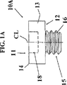
図1Aと図1Bには、本発明による切削インサート10Aが示されており、この切削インサートは縦方向の旋削のためのものであることが好ましい。切削インサート10AはいわゆるRタイプの丸い形状を有する。この切削インサートは、上面11と、これとは反対側にあるほぼ平面の下面12とを有し、これらの上面と下面は円筒形の切れ刃面13によって互いに連結されている。この切削インサートは、上面11と切れ刃面13との間の交差線に沿って形成されている円形の切れ刃14を有する。切削インサート10Aは中心線CLを有する。切削インサートは、その切削インサートをホルダに対して締着するために使用される手段15を含む。切削インサートの直径は、この手段15の直径よりも著しく大きい。手段15は切削インサートと一体状であり、したがって切れ刃14と同一の材料で形成されている。これは、適切な装置による射出成形とその後の焼結とによって得られている。切削インサートは、焼結硬質合金とプラスチックのような有機結合剤との混合粉末によって、および、この混合粉末をペレットまたは顆粒の形に成形することによって作られる。前記ペレットまたは顆粒を射出成形法によって鋳造し、その後で得られた産物を1300℃から1500℃の温度で焼結する。この射出成形法はすでにヨーロッパ特許96913765.2号にさらに詳細に説明されており、この内容は本明細書に組み入れてある。手段15は、下面12の中央部分から垂直に突き出す。手段15は、切削インサートの中心線CLとほぼ一致する中心軸線を有する外側にねじ山が付いた差し込み16で構成される。図に示す実施形態では、ねじ山は1つの入口と1つの出口を有する。あるいは、このねじ山は、図3Bに示しているようなタイプの少なくとも2つの入口と少なくとも2つの出口とを有してもよい。このことを、手段15が1つまたは複数の螺旋形の外側溝を含むと表現することも可能である。
【0006】
切削インサート10Aの上面11、すなわち、前記手段15とは反対側にあるインサート側面11は、少なくとも1つのキーグリップ17を含む。キーグリップ17は、ホルダに対する切削インサートの締着の際にキーと協働するようになっている、輪郭形成された凹み18の形状を有する。キーグリップ17は中心軸線を有し、この中心軸線は切削インサートの中心線CLとほぼ一致する。キーグリップの輪郭はTorx(登録商標)またはアレンキー(allen key)等のタイプであり、すなわち、キーグリップを回すための面を3つ以上好ましくは6つ含む輪郭である。したがって、手段15の中心線はキーグリップ17の中心線とほぼ一致する。グリップ17は仮想円筒24内に配置されており、この仮想円筒の直径はねじ山16の平均直径にほぼ一致する。同様に、切れ刃14が1つの平面内に設けられていることが好ましいということに留意されたい。切れ刃14は、キーグリップの半径方向に外側にかつ中心線CLに関してキーグリップから一定の距離に設けられていることによって、キーグリップ17を取り囲む。
【0007】
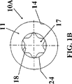
図2A〜2Dは、ホルダ20Aと切削インサート10Aとを含む本発明による旋削工具19Aを示す。ホルダ20Aはシャンクを含み、このシャンクの一方の端部は切削インサートポケットを備えており、その他方の端部は旋削のための機械の中に締め付け固定されるように設けられている。ホルダは鋼で作られている。図2Dに示すように、切削インサートポケットは底部面21と側支持面22とを含む。ホルダ20Aは、ねじ山付き穴23の形状の切削インサートポケット内に切削インサートを締着するための手段を含み、この穴23は底部面21の平面に対してほぼ垂直に延びる。図に示す実施形態では、穴23内のねじ山は1つの入口と1つの出口を有する。あるいは、このねじ山は少なくとも2つの入口と少なくとも2つの出口を有してもよい。このことを、手段23が1つまたは複数の螺旋形の内側ねじ山を含むと表現することも可能である。
【0008】
穴23は、ほぼ円形の底部面の中央に設けられている。側支持面22は、切削インサートの凸形切れ刃面13に適合するように部分円筒形に凹んでいる。
ホルダ20A内への切削インサート10Aの装着を次のように行う。切削インサートを、差込み(spigot)15の中心線が穴23の中心線と整合するように、切削インサートポケットの底部面21に向かう方向に移動させる。切削インサートを、ねじ山が互いに突き当たるように切削インサートポケットに向けて押す。その次に、切削インサートの下面12が切削インサートポケットの底部面21に突き当たるまで、切削インサート10Aとその関連のねじ山付き差し込み15とを、手によって、または、キーグリップ17と係合した適切なキー(図示していない)を使用して、一体のユニットとして回転させる。その次に、穴23内のより弾性が高い鋼ねじ山に予引張力を生じさせるように、底部面に対して切削インサートを堅固に締着するために、キーを使用しなければならない。この好ましい実施形態では、切削インサート10Aは約4mmの直径とメートルねじM2.2とキーグリップT07とを有する。さらに一般的には、切削インサートの直径の間隔が3〜5mmの範囲内にある。ねじ山は任意のタイプであってよく、随意に右ねじれでも左ねじれでもあってよい。焼結超硬合金によく適するねじ山のタイプがロープねじ山である(図2Eを参照されたい)。図2Eのねじ山が左ねじれのねじ山であり、このねじ山は、機械加工中に丸い切れ刃14と共にねじ連結の形に締着するようになっている。
【0009】
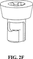
あるいは、差し込み15のねじ山を1つまたは複数の螺旋形の溝で置き換えることが可能であり、この螺旋形溝の周方向の寸法は360°よりも小さい。その次に、図2Fに示すように、この1つまた複数の溝は、差込み連結部を生じさせるためにホルダの穴内の対応する1つまたは複数の突起と嵌合し、このことが、新たな切れ刃を有する少なくとも2つの位置に切削インサートを割出しすることを可能にする。あるいは、切削インサートの割出しを、ホルダの底部面と切削インサートの下面の間にはさみ金を設けることによって実現してもよい。180°の割出しを得るために、このはさみ金の厚さをねじ山のピッチの半分に選択してもよい。
【0010】
図3Aには、本発明による工具19Bの別の実施形態が示してある。この実施形態と上述の工具との間の相違点は、部分的には、切削インサート10Bがポジ基本的形状を有することと、部分的には、側支持面が無いことである。これによって、切削力の全てが底部面とホルダ20B内のねじ山とによって受け取られる。
【0011】
図4Aには、本発明による切削インサート10Cと工具19Cの別の実施形態が示してある。この実施形態と図3Aによる上述の工具との間の相違点は、差し込みとホルダの穴の両方が、仮想円筒24を超えて半径方向に設けられている円筒形の案内面25、26をそれぞれに含むということである。案内面25、26の直径は、互の滑り嵌めを実現するようになっている。この場合に、全ての切削力が底部面と案内面25、26とホルダ内のねじ山とによって受け取られる。
【0012】
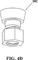
図4Bには、本発明による切削インサート10Cと工具19Iの別の実施形態が示してある。この実施形態と図4Aによる上述の工具との間の相違点は、この場合に、ホルダ内のねじ山が、Torx(登録商標)グリップを有するルーズナット内のねじ山によって置き換えられているということである。このナットと切削インサート10Cは、切削インサートの取付けまたは取外しのために互いに相対回転させられる。図4Cは、このナットと図4Aからの切削インサート10Cとを示す。図4Dは、外側アレングリップを有する別のナットと図4Aからの切削インサート10Cとを示す。
【0013】
図5Aと図5Bには、本発明による切削インサート10Dの別の実施形態が示してある。この実施形態と図3Aによる上述の工具との間の相違点は、切削インサートの切れ刃面すなわち逃げ面が凹状であり、2つの互いに円周方向の部分の交差線に向かって破損を案内するために、この2つの互いに円周方向の部分を含むということである。
【0014】
図6には、本発明による切削インサート10Eの別の実施形態が平面図の形で示してある。この実施形態と上述の工具との間の相違点は、キーグリップが六角形の凹み、すなわち、いわゆるアレングリップで構成されているということである。
図7Aと図7Bには、本発明による切削インサート10fの別の実施形態が示してある。この実施形態と図3Aによる上述の工具との間の相違点は、キーグリップが切削インサート上の輪郭形成された突起を含むということである。この突起は、いわゆるTorx(登録商標)連結部のための雄側部分を含む。この突起は、類似しているが逆になった形状を有する雌側部分と協働する。この突起は、さらに、チップフォーマまたはチップブレーカとしても機能する。あるいは、この突起は、横断面が六角形の突起であるアレンキー(allen key)連結部の雄側部分から成ってもよい。しかし、この突起は、小さい直径と小さい切りくず空間とを有する工具の上述の凹みよりも劣る技術的解決策と見なすこともできる。
【0015】
図8Aと図8Bには、本発明による切削インサート10Gの別の実施形態が示してある。この実施形態と図3Aによる上述の工具との間の相違点は、この場合には螺旋状に形成された溝が切削インサート内の中央凹み27内で機能させられるということである。この凹み27は、切削インサートの中間部分を超えてキーグリップ凹みの中に延びる。この凹みのねじ山はホルダ内のねじと協働する。このねじはホルダ内に堅固に固定されているか、または、ホルダ内で回転自在である。この凹みは1つまたは複数の螺旋形の内側溝を含む。
【0016】
図9には、本発明による切削インサート10Hの別の実施形態が示してある。この実施形態と図8Aと図8Bとによる上述の工具との間の相違点は、キーグリップが突起であるということである。
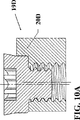
図10Aと図10Bには、図5Aと図5Bによる切削インサート10Dを有する本発明による工具19Dの別の実施形態が示してある。この実施形態と図2Dによる上述の工具との間の相違点は、実質的に、ねじ山が付いておりかつ拡大されているホルダ穴が、側支持面に向かう方向に一定の間隔を置いて配置されており、したがってそのホルダ穴の中心線が切削インサートの中心線から前記方向にずれているということである。この穴の最小直径は差し込みの最大直径よりも大きいので、差し込みはホルダの穴の中により長く挿入されることが可能であり、その後で、切削インサートの回転が開始することが可能である。それによって、側支持面とは反対側を向いているねじ山の一部分だけが、切削インサートの切れ刃面が側支持面に突き当たってこれを支持する時に、これと同時に締め付け係合状態にあるだろう。この仕方で迅速なねじ機能が得られる。前記特徴は、中心線が互いに一致する互いにほぼ同一の円錐形のねじ山によっても得ることが可能である。
【0017】
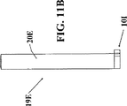
図11A〜11Cには、本発明による工具19Eと切削インサート10Iの別の実施形態が示してある。工具19Eは内側溝削り用であり、円筒形ホルダと、突出切削部分を有する溝削りインサート101とを含む。この切削インサートは上述の仕方で装着されており、切削部分の切れ刃の最終位置を予め決めるために、ねじ山の形状を随意に準備することが可能である。
【0018】
図12A〜12Cには、本発明による工具19Fと切削インサート10Jの別の実施形態が示してある。工具19Fは例えばエンドミル削り用であり、各々の切りくずを割出す円筒形の切削インサート10Jを含む。この切削インサートは上述の仕方で装着されており、この切削インサートは幾つかの対称配置された切削部分を含み、かつ、回転させられるようになっているので、割出しは不要である。あるいは、この切削インサートは、切りくず分割円筒形エンドミル削りインサート、ねじフライス削りインサート、ブローチ削りインサート、鳩尾形スロットのエンドミル削りのための円錐台形工具取付けヘッドとして開発されており、後者は、ホルダに向かって方向付けられた円錐形の先端またはその類似物を有する。これらの工具に共通しているのは、これらの工具が、高速度鋼製のエンドミルの場合にはより小さい寸法(直径5〜15mm)が望ましいことが多いので、従来の高速度鋼製のエンドミルに取って代わるということである。
【0019】
図13A〜13Cには、本発明による、図3Aに示してある工具19Gと切削インサート10Bとの別の実施形態が示してある。工具19Gは例えば溝削り用であり、2つの切削インサート10Bを含み、この切削インサートの一方は工具の回転軸線に重なり、したがってフライスが穿孔することも可能である。
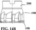
図14A〜14Cには、本発明による、図3Aに示してある工具19Hと切削インサート10Bとの別の実施形態が示してある。工具19Hは例えば正面フライス削り用であり、8つの切削インサート10Bを含む。
【0020】
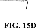
図15Aと図15Bには、本発明による切削インサート10Kの別の実施形態が示してある。この実施形態と図3Aによる上述の工具との間の相違点は、切削インサートの上面11がチップブレーカを含むということである。補強面取り部が切れ刃14に連続している。この補強面取り部は、さらに、隆起した後面に連続する凹状の切りくず面に連続する。図15Cは、補強面取り部が存在しない図15Bと同様の別の断面を示す。図15Cでは、突起が点線で示してある。この場合には、幾つかの個々の突起には、切りくず面の外周に沿って均一な隔壁が備えられている。図15Dは、凹状の切りくず面を含まない図15Bと同様の別の断面を示す。平面の切りくず面が補強面取り部に連続する。図15Dでは、凹みが点線で示してある。この場合には、幾つかの個々の凹みには、切りくず面の外周に沿って均一な隔壁が備えられている。
【0021】
図16には、本発明による切削インサート10Lの別の実施形態が示してある。この実施形態と図3Aによる上述の工具との間の相違点は、切削インサートの上面11が、超硬合金よりも耐摩耗性が高い材料(例えば立方晶系窒化ホウ素またはダイヤモンド)のリングを含むということである。このリングはキーグリップを取り囲む。
【0022】
したがって、本発明は、切削機械加工用の工具と、改善された強度を有しかつ取り扱いが容易な切削インサートと、こうした切削インサートを容易に装着するための方法とに関する。さらに明確に述べると、切削インサート自体がねじまたはナットとして設計されていて、公知の技術による工具と共に現在使用されている、小さい直径を有する取り扱い難いねじが回避される。上述の国際出願WO 98/13161号による解決策は、側支持面が存在する旋削工具には適していないが、これは、側支持面が回転時におけるキーの1つのアームの動きを妨げるからである。本発明をその好ましい実施形態に関して説明してきたが、具体的には説明していない追加と変更と置き換えと削除が、添付の特許請求項によって定義されている通りの本発明の着想と範囲から逸脱することなしに行われることが可能であるということを、当業者は理解するだろう。従って、本明細書で示した実施形態を、本特許出願では具体的に示していない工具および切削インサートと組み合わせることが可能である。
【図面の簡単な説明】
【図1】 図1Aは本発明による切削インサートを側面図の形で示し、図1Bは切削インサートを平面図の形で示す。
【図2】 図2A〜2Cは、本発明による旋削工具をそれぞれに側面図、平面図、斜視図の形で示し、図2Dは図2Bの線IIに沿った断面図を示し、図2Eは本発明による切削インサートの別の実施形態を側面図の形で示し、且つ図2Fは、本発明による切削インサートの別の実施形態を斜視図の形で示す。
【図3】 図3Aは本発明による工具の別の実施形態を断面図の形で示し、図3Bは本発明による切削インサートの別の実施形態を斜視図の形で示す。
【図4】 図4Aは本発明による切削インサートと工具との別の実施形態を断面図の形で示し、図4Bは本発明による切削インサートと工具との別の実施形態を断面図の形で示し、且つ4C及び4Dは、様々な種類のナットと組み合わされた図4Aの切削インサートを示す。
【図5】 図5Aと図5Bは、本発明による切削インサートの別の実施形態をそれぞれに側面図と平面図の形で示す。
【図6】 図6は、本発明による切削インサートの別の実施形態を平面図の形で示す。
【図7】 図7Aと図7Bは、本発明による切削インサートの別の実施形態をそれぞれに側面図と平面図の形で示す。
【図8】 図8Aと図8Bは、本発明による切削インサートの別の実施形態をそれぞれに断面図と平面図の形で示す。
【図9】 図9は、本発明による切削インサートの別の実施形態を断面図の形で示す。
【図10】 図10Aと図10Bは本発明による工具の別の実施形態をしめし、図10Bの平面図と、この断面図の線Xに沿った断面図との形で図10Aに示す。
【図11】 図11A〜11Cは、本発明による旋削工具の別の実施形態をそれぞれに端面図と側面図と斜視図の形で示す。
【図12】 図12A〜12Cは、本発明によるフライス削り工具の別の実施形態をそれぞれに端面図と側面図と斜視図の形で示す。
【図13】 図13A〜13Cは、本発明によるフライス削り工具の別の実施形態をそれぞれに端面図と側面図と斜視図の形で示す。
【図14】 図14A〜14Cは、本発明による追加のフライス削り工具の別の実施形態をそれぞれに端面図と側面図と斜視図の形で示す。
【図15】 図15Aは本発明による切削インサートの別の実施形態を斜視図の形で示し、図15Bは図15Aの切削インサートを断面図の形で示し、且つ図15Cと図15Dは図15Aによる切削インサートの別の断面を示す。
【図16】 図16は、本発明による切削インサートの別の実施形態を斜視図の形で示す。[0001]
The present invention relates to a tool for cutting machining, a cutting insert and a method for mounting such a cutting insert according to the preamble of the independent claim.
[0002]
Prior art Conventionally, circular indexable inserts with a diameter of up to about 5 mm have been used. The smallest circular indexable insert can be thought of as a cemented carbide ring to provide sufficient space to accommodate the screws holding the cutting insert within the cutting insert pocket. A ball nose milling blade including a milling tool mounting head mounted on a shank via a pull bar is known from international application WO 98/13161. The milling tool mounting head is made of injection-molded cemented carbide and has a cutting edge extending toward the rotational axis of the tool. This milling tool mounting head has a thread that is integral with the cutting edge and is therefore made of the same material as the cutting edge. The milling tool mounting head includes a key grip consisting of planar surfaces positioned diametrically opposite one another. An injection molded cutting insert with an integral thread is known from international application WO 95/33590. An end mill is known from U.S. Pat. No. 5,496,137 with a mounting head which has an integral thread and is manufactured according to the older prior art. The problem with prior art tools is that if these tools are of small dimensions, the resulting strength is lower and the handling of the tools is difficult.
[0003]
Objects of the Invention One of the objects of the present invention is to provide a tool for cutting machining that has the advantages of prior art tools.
Another object of the present invention is to provide a tool for cutting machining and a cutting insert with improved strength and easy handling.
[0004]
Yet another object of the present invention is to provide a tool for cutting machining and a cutting insert that are designed such that the cutting insert is more tightly clamped during machining.
Yet another object of the present invention is to provide a method for easily mounting such cutting inserts.
[0005]
These and other objects are achieved by a tool for cutting machining, a cutting insert and a method for mounting such a cutting insert as defined in the appended claims with reference to the accompanying drawings. Realized.
Detailed Description of the Preferred Embodiments of the Invention FIGS. 1A and 1B show a
[0006]
The
[0007]
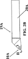
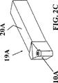
2A-2D show a
[0008]
The
The
[0009]
Alternatively, the thread of the
[0010]
FIG. 3A shows another embodiment of a
[0011]
FIG. 4A shows another embodiment of a
[0012]
FIG. 4B shows another embodiment of a
[0013]
5A and 5B show another embodiment of a
[0014]
FIG. 6 shows another embodiment of a
7A and 7B show another embodiment of a cutting insert 10f according to the present invention. The difference between this embodiment and the tool described above according to FIG. 3A is that the key grip includes a contoured protrusion on the cutting insert. This projection includes a male part for the so-called Torx® connection. This protrusion cooperates with a female portion having a similar but inverted shape. This protrusion further functions as a chip former or chip breaker. Alternatively, the protrusion may comprise a male side portion of an allen key connecting portion having a hexagonal cross section. However, this protrusion can also be regarded as a technical solution which is inferior to the above-mentioned recess of a tool having a small diameter and a small chip space.
[0015]
8A and 8B show another embodiment of a
[0016]
FIG. 9 shows another embodiment of a
10A and 10B show another embodiment of a
[0017]
11A-11C illustrate another embodiment of a
[0018]
12A-12C show another embodiment of a
[0019]
13A-13C illustrate another embodiment of the
14A-14C show another embodiment of the
[0020]
15A and 15B show another embodiment of a
[0021]
FIG. 16 shows another embodiment of a
[0022]
Accordingly, the present invention relates to a tool for cutting machining, a cutting insert having improved strength and easy handling, and a method for easily mounting such a cutting insert. More specifically, the cutting insert itself is designed as a screw or nut, avoiding unwieldy screws with small diameters currently used with tools according to known technology. The solution according to the above-mentioned international application WO 98/13161 is not suitable for turning tools with side support surfaces, since the side support surfaces prevent the movement of one arm of the key during rotation. is there. Although the invention has been described in terms of its preferred embodiments, additions, changes, substitutions and deletions not specifically described depart from the spirit and scope of the invention as defined by the appended claims. Those skilled in the art will appreciate that it can be done without doing so. Accordingly, the embodiments shown herein can be combined with tools and cutting inserts not specifically shown in this patent application.
[Brief description of the drawings]
FIG. 1A shows a cutting insert according to the invention in the form of a side view, and FIG. 1B shows the cutting insert in the form of a plan view.
2A to 2C show respectively the turning tool according to the invention in the form of a side view, a plan view and a perspective view, FIG. 2D shows a cross-sectional view along line II in FIG. 2B, and FIG. Another embodiment of a cutting insert according to the present invention is shown in side view and FIG. 2F shows another embodiment of a cutting insert according to the present invention in perspective view.
FIG. 3A shows another embodiment of a tool according to the invention in the form of a cross-section, and FIG. 3B shows another embodiment of a cutting insert according to the invention in the form of a perspective view.
4A shows another embodiment of a cutting insert and tool according to the present invention in cross-sectional view, and FIG. 4B shows another embodiment of a cutting insert and tool according to the present invention in cross-sectional view. 4C and 4D show the cutting insert of FIG. 4A combined with various types of nuts.
5A and 5B show another embodiment of a cutting insert according to the present invention in the form of a side view and a plan view, respectively.
FIG. 6 shows, in plan view, another embodiment of a cutting insert according to the invention.
7A and 7B show another embodiment of a cutting insert according to the present invention in the form of a side view and a plan view, respectively.
8A and 8B show another embodiment of a cutting insert according to the present invention in the form of a cross-sectional view and a plan view, respectively.
FIG. 9 shows another embodiment of a cutting insert according to the invention in the form of a cross-sectional view.
10A and 10B show another embodiment of a tool according to the present invention, shown in FIG. 10A in the form of a plan view of FIG. 10B and a cross-sectional view along line X of this cross-sectional view.
11A-11C show another embodiment of a turning tool according to the present invention in the form of an end view, a side view and a perspective view, respectively.
12A-12C show another embodiment of a milling tool according to the invention in the form of an end view, a side view and a perspective view, respectively.
FIGS. 13A-13C show another embodiment of a milling tool according to the present invention in the form of an end view, a side view and a perspective view, respectively.
FIGS. 14A-14C show another embodiment of an additional milling tool according to the present invention in the form of an end view, a side view and a perspective view, respectively.
15A shows another embodiment of a cutting insert according to the present invention in the form of a perspective view, FIG. 15B shows the cutting insert of FIG. 15A in the form of a cross-sectional view, and FIGS. 15C and 15D show FIG. Figure 3 shows another cross section of a cutting insert according to.
FIG. 16 shows another embodiment of a cutting insert according to the invention in the form of a perspective view.
Claims (13)
前記第1の手段(15、27)とは反対側にあるインサート(11)の一方の面が、前記切削インサート(10A〜10L)を前記ホルダに押し付けて締め付ける際にキーと協働するようになっている少なくとも1つのキーグリップ(17)を含み、
前記キーグリップ(17)が、前記切削インサート(10A〜10L)の周辺切れ刃部の半径方向の内側に位置し且つ取り囲まれ、且つ
機械的に押し付けて締め付けるための第1の手段(15、27)が、前記切削インサートにネジ切り部または指し込み部を含む、
ことを特徴とする切削インサート。A cutting insert for chip removing machining including at least one cutting edge (14), the cutting insert (10a-101) is made of cemented carbide, mechanical the cutting insert holder A first insert (15, 27) for pressing and tightening to the cutting insert, wherein the means (15, 27) is integral with the cutting insert;
One surface of the insert (11) on the opposite side of the first means (15, 27) cooperates with the key when pressing the cutting insert (10A-10L) against the holder and tightening Comprising at least one key grip (17),
It said key grip (17), the cutting insert peripheral cutting edge portion radial positioned inside and take circumference rare in (10a-101), and mechanically pressing the first means for tightening (15, 27) comprises a threaded portion or the pointing addition unit in the cutting insert DOO,
Cutting insert characterized by that.
前記第1の手段(15、27)の反対側にある前記インサート(11)の一方の面が、前記切削インサート(10A〜10L)を前記ホルダ(20A〜20I)に押し付けて締め付ける際にキーと協働するようになっている少なくとも1つのキーグリップ(17)を含み、
前記キーグリップ(17)が、前記切削インサート(10A〜10L)の周辺切れ刃部の半径方向の内側に位置し且つ取り囲まれ、且つ
機械的に押し付けて締め付けるための第1の手段(15、27)及び第2の手段(23)が、前記切削インサート及び前記ホルダの対応する部分にネジ切り部または差し込み部を含む、
ことを特徴とする工具。A tool for chip removal machining comprising a holder (20A-20I) and at least one cutting insert (10A-10L) having at least one cutting edge (14), said tool (19A-19I) ) Includes means (15, 23, 27) for mechanically pressing and clamping the cutting insert against the holder, wherein the first means (15, 27) is integrated with the cutting insert (10A to 10L). consists is enabled with cemented carbide with Jo, second means (23) is coupled to said holder (20A~20L) of said means, said cutting insert cooperating support surface and said holder (12, 21 )
When one surface of the insert (11) on the opposite side of the first means (15, 27) presses the cutting insert (10A to 10L) against the holder (20A to 20I) and tightens it, Including at least one key grip (17) adapted to cooperate;
It said key grip (17), the cutting insert peripheral cutting edge portion radial positioned inside and take circumference rare in (10a-101), and mechanically pressing the first means for tightening (15, 27) and second means (23) include threaded or inserted portions in corresponding portions of the cutting insert and the holder,
A tool characterized by that.
前記ホルダの切削インサート及び対応する部分にネジ切り部分または差し込み部分として機械的に押し付けて締め付けるため第1及び第2の手段(15、23,27)を備える工程と、
前記第1の手段(15、27)の反対側にある前記インサート(11)の一方の面に少なくとも1つのキーグリップ(17)を設ける工程と、
前記キーグリップ(17)が、前記切削インサート(10A〜10L)の周辺切れ刃部の半径方向の内側に位置し且つ取り囲まれる工程と、
前記手段(15、27、23)を互いに係合させる工程と、
キーを前記キーグリップ(17)と係合させる工程と、
少なくとも前記支持面(12、21)が互いに突き当たるまで前記切削インサート(10A〜10L)と前記第1の手段(15、23)とが一体のユニットとして回転させられるように、前記キーを回転させる工程と、
を含むことを特徴とする方法。A method of attaching a cutting insert to a holder, wherein the tool (19A to 19I) is a first means (15) for mechanically pressing and tightening the cutting insert (10A to 10L) against the holder (20A to 20I). , and a 27) and second means (23), first means of said means (15, 27) consists of the cutting insert (10a-101) and an integral form or one cemented carbide, wherein A second means (23) of means is connected to the holder (20A-20I), wherein the holder and the cutting insert have cooperating support surfaces (12, 21),
Providing first and second means (15, 23, 27) for mechanically pressing and tightening the cutting insert and corresponding part of the holder as a threaded part or an insert part;
Providing at least one key grip (17) on one side of the insert (11) on the opposite side of the first means (15, 27);
It said key grip (17), and and takes circumference Murrell step located radially inward of the peripheral cutting edge portion of the cutting insert (10a-101),
Engaging said means (15, 27, 23) with each other;
Engaging a key with the key grip (17);
The step of rotating the key so that the cutting insert (10A to 10L) and the first means (15, 23) are rotated as an integral unit at least until the support surfaces (12, 21) abut each other. When,
A method comprising the steps of:
Applications Claiming Priority (3)
| Application Number | Priority Date | Filing Date | Title |
|---|---|---|---|
| SE9804458A SE519123C2 (en) | 1998-12-22 | 1998-12-22 | Cuts and tools for cutting machining and method of mounting cutters therein |
| SE9804458-9 | 1998-12-22 | ||
| PCT/SE1999/002309 WO2000037202A1 (en) | 1998-12-22 | 1999-12-10 | Tool for cutting machining |
Publications (3)
| Publication Number | Publication Date |
|---|---|
| JP2002532270A JP2002532270A (en) | 2002-10-02 |
| JP2002532270A5 JP2002532270A5 (en) | 2007-02-08 |
| JP4489964B2 true JP4489964B2 (en) | 2010-06-23 |
Family
ID=20413783
Family Applications (1)
| Application Number | Title | Priority Date | Filing Date |
|---|---|---|---|
| JP2000589300A Expired - Fee Related JP4489964B2 (en) | 1998-12-22 | 1999-12-10 | Tools for cutting machining |
Country Status (7)
| Country | Link |
|---|---|
| US (1) | US6273650B1 (en) |
| EP (1) | EP1140401B1 (en) |
| JP (1) | JP4489964B2 (en) |
| KR (1) | KR100675922B1 (en) |
| CN (1) | CN1096324C (en) |
| SE (1) | SE519123C2 (en) |
| WO (1) | WO2000037202A1 (en) |
Families Citing this family (24)
| Publication number | Priority date | Publication date | Assignee | Title |
|---|---|---|---|---|
| DE10113633B4 (en) * | 2001-03-21 | 2006-04-13 | Jakob Lach Gmbh & Co. Kg | Profile-turning tool |
| DE60224276T2 (en) * | 2001-05-21 | 2008-12-18 | Murofushi, Kimiko | CANCER METASTASIS HEMMER WITH CARBACYCLIC PHOSPHATIDINE ACID DERIVATIVES |
| IL145574A0 (en) * | 2001-09-24 | 2002-06-30 | Iscar Ltd | Cutting tool and cutting insert therefor |
| IL150783A0 (en) * | 2001-10-16 | 2003-02-12 | Iscar Ltd | Cutting tool and cutting insert therefor |
| IL148475A (en) * | 2002-03-04 | 2007-09-20 | Gil Hecht | Cutting tool |
| SE526539C2 (en) * | 2002-05-28 | 2005-10-04 | Sandvik Intellectual Property | Chip separation machining tool where the cutting position has flexible portions. |
| SE526255C2 (en) * | 2003-03-14 | 2005-08-09 | Sandvik Intellectual Property | Tools and indexable inserts for fine turning of rotationally symmetrical grooves in workpieces |
| SE526392C2 (en) * | 2003-08-28 | 2005-09-06 | Seco Tools Ab | Tool arrangement and chip cutting tools where the tool has a channel of non-circular cross section |
| US8573901B2 (en) * | 2003-09-02 | 2013-11-05 | Kennametal Inc. | Assembly for rotating a cutting insert during a turning operation and inserts used therein |
| DE102004006388A1 (en) * | 2004-02-09 | 2005-08-25 | Aleit Gmbh | Insert milling cutters |
| DE102004026873A1 (en) * | 2004-06-02 | 2005-12-29 | NUBIUS GROUP Präzisionswerkzeuge GmbH | Cutting tool and cutting insert for a cutting tool |
| SE528251C2 (en) * | 2004-09-24 | 2006-10-03 | Seco Tools Ab | Trade for tools and tools with a transition part between a threaded part and a supporting part |
| SE528299C2 (en) * | 2004-09-24 | 2006-10-17 | Seco Tools Ab | Cutting tip and cutting tool with holder part designed as truncated conical thread |
| IL165294A (en) * | 2004-11-18 | 2009-07-20 | Amir Satran | Milling cutting insert and milling cutter |
| DE102006035182A1 (en) * | 2006-07-29 | 2008-01-31 | Hartmetall-Werkzeugfabrik Paul Horn Gmbh | Tool system, has cutting blade protruding over holder, where holder is provided with supporting part protruding towards projection of cutting blade and forming supporting surface for partial attachment of cutting tool |
| US7648313B2 (en) * | 2006-09-19 | 2010-01-19 | Esco Technologies, Inc. | Tube end milling head |
| US7905686B2 (en) * | 2007-07-02 | 2011-03-15 | Esco Technologies, Inc. | System for removing boiler tube stubs |
| US7806633B2 (en) * | 2008-03-04 | 2010-10-05 | Kennametal Inc. | Cutting insert with threaded hole and cutting tool therefor |
| DE102010004526B4 (en) * | 2010-01-14 | 2014-05-22 | Kennametal Inc. | cutting tool |
| EP2383062B1 (en) | 2010-04-30 | 2013-07-10 | Seco Tools AB | Milling tool with clamping screw having male grip at end thereof |
| CN102601397A (en) * | 2012-03-29 | 2012-07-25 | 株洲华锐硬质合金工具有限责任公司 | Turning blade for turning circular profile of train wheel and method for manufacturing turning blade |
| EP2933047B1 (en) * | 2014-04-16 | 2017-03-01 | Sandvik Intellectual Property AB | A cutting tool for chip removing machining and cutting edge changing apparatus therefore |
| JP6538355B2 (en) * | 2015-01-06 | 2019-07-03 | 中村留精密工業株式会社 | Turning tool and true ball machining method |
| JP2022106578A (en) * | 2021-01-07 | 2022-07-20 | 三菱マテリアル株式会社 | Cutting insert, holder, and cutting edge replacement type cutting tool |
Family Cites Families (15)
| Publication number | Priority date | Publication date | Assignee | Title |
|---|---|---|---|---|
| US280146A (en) * | 1883-06-26 | Cutter and holder for lathes | ||
| US41517A (en) * | 1864-02-09 | Improvement in augers for boring wood | ||
| US1458802A (en) * | 1919-08-02 | 1923-06-12 | Williams J H & Co | Tool holder and tool |
| US1926531A (en) * | 1931-02-25 | 1933-09-12 | Charles M Hartt | Multiple tool and holder |
| SE378370B (en) * | 1974-10-18 | 1975-09-01 | Sandvik Ab | |
| US4197042A (en) * | 1977-12-15 | 1980-04-08 | Everede Tool Company | Countersinking tool |
| DE3106120A1 (en) * | 1981-02-19 | 1983-01-13 | Iscar Hartmetall GmbH, 7505 Ettlingen | TOOL HOLDER TO RECEIVE A CUTTING INSERT |
| EP0121441A3 (en) * | 1983-04-04 | 1985-11-06 | General Electric Company | Improved insert for a metal cutting tool |
| IL106697A (en) | 1993-08-15 | 1996-10-16 | Iscar Ltd | Cutting insert with integral clamping means |
| US5733073A (en) * | 1994-03-31 | 1998-03-31 | Kennametal Inc. | Cutting tool assembly and cutting tool bit |
| SE504338C2 (en) | 1994-06-07 | 1997-01-13 | Sandvik Ab | Cutting plate |
| SE509218C2 (en) * | 1994-08-29 | 1998-12-21 | Sandvik Ab | shaft Tools |
| SE509207C2 (en) | 1995-05-04 | 1998-12-14 | Seco Tools Ab | Tools for cutting machining |
| US5795120A (en) * | 1996-05-13 | 1998-08-18 | Hurdle; Donald R. | Reduced-friction thread forming or thread cutting screw |
| SE509931C2 (en) | 1996-09-27 | 1999-03-22 | Seco Tools Ab | Swivel mill, swivel head and method of mounting a removable swivel head on a shaft for a swivel |
-
1998
- 1998-12-22 SE SE9804458A patent/SE519123C2/en not_active IP Right Cessation
-
1999
- 1999-12-10 JP JP2000589300A patent/JP4489964B2/en not_active Expired - Fee Related
- 1999-12-10 WO PCT/SE1999/002309 patent/WO2000037202A1/en active IP Right Grant
- 1999-12-10 CN CN99813702A patent/CN1096324C/en not_active Expired - Fee Related
- 1999-12-10 EP EP99964848A patent/EP1140401B1/en not_active Revoked
- 1999-12-10 KR KR1020017007921A patent/KR100675922B1/en not_active IP Right Cessation
- 1999-12-22 US US09/468,904 patent/US6273650B1/en not_active Expired - Lifetime
Also Published As
| Publication number | Publication date |
|---|---|
| US6273650B1 (en) | 2001-08-14 |
| CN1328494A (en) | 2001-12-26 |
| SE9804458L (en) | 2000-06-23 |
| CN1096324C (en) | 2002-12-18 |
| KR20020020677A (en) | 2002-03-15 |
| SE519123C2 (en) | 2003-01-14 |
| EP1140401B1 (en) | 2013-01-23 |
| WO2000037202A1 (en) | 2000-06-29 |
| EP1140401A1 (en) | 2001-10-10 |
| KR100675922B1 (en) | 2007-01-29 |
| JP2002532270A (en) | 2002-10-02 |
| SE9804458D0 (en) | 1998-12-22 |
Similar Documents
| Publication | Publication Date | Title |
|---|---|---|
| JP4489964B2 (en) | Tools for cutting machining | |
| US5971670A (en) | Shaft tool with detachable top | |
| EP2368657B1 (en) | A rotatable tool for chip removing machining as well as a cutting insert and a basic body therefor | |
| CA2485651C (en) | Rotary cutting tool | |
| US8226333B2 (en) | Tool for chip removing machining as well as a part and threaded joint therefor | |
| EP1296791B1 (en) | Rotatable tool having a replaceable tip at the chip removing free end of the tool | |
| EP1328366B1 (en) | Rotatable tool having a replaceable cutting part at the chip removing free end of the tool | |
| US8573909B2 (en) | Tool coupling | |
| EP1899098B1 (en) | A turning tool and an indexable turning insert as well as an attachment for such turning tools | |
| US20030118413A1 (en) | Tool for rotary chip removal, a tool tip and a method for manufacturing a tool tip | |
| KR20110124156A (en) | Indexable milling insert for milling tools | |
| US8708613B2 (en) | Left-handed and right-handed cutting tool | |
| IL195601A (en) | Clamping mechanism | |
| US5542794A (en) | Multi-handed milling cutter having indexable wedges and inserts | |
| US20080101878A1 (en) | Tool for cutting machining | |
| CN219541918U (en) | Combined hard alloy handle type gear shaping cutter | |
| JP3539210B2 (en) | Head exchangeable cutting tool and method of manufacturing the same | |
| CA2201717C (en) | Multi-handed milling cutter having indexable wedges and inserts |
Legal Events
| Date | Code | Title | Description |
|---|---|---|---|
| A521 | Written amendment |
Free format text: JAPANESE INTERMEDIATE CODE: A523 Effective date: 20061211 |
|
| A621 | Written request for application examination |
Free format text: JAPANESE INTERMEDIATE CODE: A621 Effective date: 20061211 |
|
| A131 | Notification of reasons for refusal |
Free format text: JAPANESE INTERMEDIATE CODE: A131 Effective date: 20091006 |
|
| A521 | Written amendment |
Free format text: JAPANESE INTERMEDIATE CODE: A523 Effective date: 20100104 |
|
| TRDD | Decision of grant or rejection written | ||
| A01 | Written decision to grant a patent or to grant a registration (utility model) |
Free format text: JAPANESE INTERMEDIATE CODE: A01 Effective date: 20100302 |
|
| A01 | Written decision to grant a patent or to grant a registration (utility model) |
Free format text: JAPANESE INTERMEDIATE CODE: A01 |
|
| A61 | First payment of annual fees (during grant procedure) |
Free format text: JAPANESE INTERMEDIATE CODE: A61 Effective date: 20100401 |
|
| FPAY | Renewal fee payment (event date is renewal date of database) |
Free format text: PAYMENT UNTIL: 20130409 Year of fee payment: 3 |
|
| R150 | Certificate of patent or registration of utility model |
Free format text: JAPANESE INTERMEDIATE CODE: R150 |
|
| FPAY | Renewal fee payment (event date is renewal date of database) |
Free format text: PAYMENT UNTIL: 20140409 Year of fee payment: 4 |
|
| R250 | Receipt of annual fees |
Free format text: JAPANESE INTERMEDIATE CODE: R250 |
|
| R250 | Receipt of annual fees |
Free format text: JAPANESE INTERMEDIATE CODE: R250 |
|
| R250 | Receipt of annual fees |
Free format text: JAPANESE INTERMEDIATE CODE: R250 |
|
| LAPS | Cancellation because of no payment of annual fees |