JP4488630B2 - Energy extraction method and apparatus - Google Patents
Energy extraction method and apparatus Download PDFInfo
- Publication number
- JP4488630B2 JP4488630B2 JP2000620249A JP2000620249A JP4488630B2 JP 4488630 B2 JP4488630 B2 JP 4488630B2 JP 2000620249 A JP2000620249 A JP 2000620249A JP 2000620249 A JP2000620249 A JP 2000620249A JP 4488630 B2 JP4488630 B2 JP 4488630B2
- Authority
- JP
- Japan
- Prior art keywords
- force
- boundary
- energy
- kashmir
- distance
- Prior art date
- Legal status (The legal status is an assumption and is not a legal conclusion. Google has not performed a legal analysis and makes no representation as to the accuracy of the status listed.)
- Expired - Fee Related
Links
Images


Classifications
-
- H—ELECTRICITY
- H02—GENERATION; CONVERSION OR DISTRIBUTION OF ELECTRIC POWER
- H02N—ELECTRIC MACHINES NOT OTHERWISE PROVIDED FOR
- H02N11/00—Generators or motors not provided for elsewhere; Alleged perpetua mobilia obtained by electric or magnetic means
-
- F—MECHANICAL ENGINEERING; LIGHTING; HEATING; WEAPONS; BLASTING
- F03—MACHINES OR ENGINES FOR LIQUIDS; WIND, SPRING, OR WEIGHT MOTORS; PRODUCING MECHANICAL POWER OR A REACTIVE PROPULSIVE THRUST, NOT OTHERWISE PROVIDED FOR
- F03G—SPRING, WEIGHT, INERTIA OR LIKE MOTORS; MECHANICAL-POWER PRODUCING DEVICES OR MECHANISMS, NOT OTHERWISE PROVIDED FOR OR USING ENERGY SOURCES NOT OTHERWISE PROVIDED FOR
- F03G7/00—Mechanical-power-producing mechanisms, not otherwise provided for or using energy sources not otherwise provided for
-
- H—ELECTRICITY
- H02—GENERATION; CONVERSION OR DISTRIBUTION OF ELECTRIC POWER
- H02N—ELECTRIC MACHINES NOT OTHERWISE PROVIDED FOR
- H02N1/00—Electrostatic generators or motors using a solid moving electrostatic charge carrier
-
- H—ELECTRICITY
- H02—GENERATION; CONVERSION OR DISTRIBUTION OF ELECTRIC POWER
- H02N—ELECTRIC MACHINES NOT OTHERWISE PROVIDED FOR
- H02N11/00—Generators or motors not provided for elsewhere; Alleged perpetua mobilia obtained by electric or magnetic means
- H02N11/008—Alleged electric or magnetic perpetua mobilia
Abstract
Description
【0001】
【関連出願の申告】
本出願は、1999年5月25日に願書を提出した、米国仮出願60/135,868の優先権を主張する。
【0002】
【発明の分野】
本発明は、広く量子電磁場のような力場源からのエネルギーの抽出に関する。
【0003】
【発明の背景】
300年昔は、もし空間領域から全ての物質が除去されれば、完全に空の体積、即ち真空、になると信じられていた。100年前に、もし空間領域から全ての物質が除去されても、その領域は、なお熱輻射を含有するので、真に空ではないことが知られた。けれども、その当時、その空間領域を絶対零度に冷却するようなことで熱輻射を除去することによって、真空がなお創造できると誤って信じられていた。
【0004】
もっと最近になって、理論は、物質と熱輻射が存在しない領域中でも、宇宙のどこにおいても非熱輻射が存在すると予言し、実験が実証している。この非熱輻射は、量子レベルで生じて、仮想粒子を絶え間なく造り出しまた破壊している無作為変動の結果であると信じられている。この輻射は、しばしば「ゼロ点場」あるいは頭字語により「ZPF」と呼ばれ、またこの場に伴うエネルギーは「ゼロ点エネルギー」、「真空エネルギー」あるいは頭字語により簡単に「ZPE」と呼ばれる。
【0005】
1948年に、ヘンドリック・ビー・ジェー・カシミール(Hendrik B. J. Casmir)は、互に平行の関係に置かれた二つの完全に導電性で中性の面は、相互に引力を誘発することを理論化した。この力は、それ以来「カシミール力」と呼ばれ、これら二つの面が、これらの面の間にある電磁場のようなソースフィールドの真空エネルギーに対して有する効果から生ずる。
【0006】
カシミール力は、既述の量子レベルの活動から単独で起きると信じられる。カシミールの二つの面、あるいは、実用的には二枚の板、の存在は、量子電磁場中における無作為変動の振動の許容モードを制限する。言い換えると、板の存在は、電磁場の境界条件を自由場の条件から変えてしまう。結果的に、これらの板の間にある空間の真空電磁場エネルギー密度は、この空間の外のエネルギー密度より小さくなる(すなわち、板の間の空間における単位体積当たりの仮想粒子の数は、この空間の外における単位体積当たりの仮想粒子の数より少ない)。このエネルギー密度の差あるいは傾きは、板を一緒に押しつける力(すなわちカシミール力)を引き起こす。
【0007】
カシミール力は、観察できるという点で「実在する」が、上述した量子電気力学(「QED」)理論は、その存在を十分に説明する唯一の理論ではない。特に、確率論的電気力学(「SED」)は、別の解釈を提供するが、同じ予測をもたらしている。
【0008】
単位面積当たりのカシミール力Fcの大きさは、下記の式で与えられる。
[1] FC(s)=(π2/240)・(h'c/s4)
ここで、・は「かけ算」を意味する、
h'=h/(2π)、
hはプランクの定数、
cは真空中の光速、
sは二つの導電性表面の距離、
である。
【0009】
式[1]から、sがゼロに近づくとカシミール力FC(s)が大きくなることが明らかである。事実、距離sが約0.1μmで分けられている二枚の板の間の単位面積当たりのカシミール力は、約100ミリボルトの電位差の存在下で同じ二枚の板の間に働く単位面積当たりの静電気力に相当する。
【0010】
ZPEは、無限大のエネルギー密度を示すこと、また普遍的に存在することが期待され、それ故無限のエネルギー源であろう。これは、驚くべきことではないが、研究者達をじらし、ZPEの研究と商品化に打ち込むいくつもの努力を引き起こしてきている。この様な努力にもかかわらず、研究者達は、ZPEを商業的に利用するのに適する装置及び方法を未だに開発していない。
【0011】
【発明の概要】
本発明に係る方法のある態様では、カシミール力生成境界(例えば板等)を介して取得されるエネルギーの正味の増大または回収を可能にする幾つかの状態変化を含む、エンジンサイクルを定義する。
【0012】
本教示に係るエネルギーの変換/回収の方法の例示的な一態様は、以下のステップを含む。
【0013】
隔てられた二つのカシミール力生成境界の間のカシミール力に影響する物理因子を変更するステップ、
隔てられた二つのカシミール力生成境界の間を分離している距離を変えるステップ、
前記物理因子を前の値に戻すように、再度前記物理因子を変更するステップ、及び
前記境界の間の分離距離を元の値に戻すステップ。
【0014】
前記例示的な方法の一態様においては、変更される物理因子はカシミール力生成境界中の自由荷電担体の濃度である。自由荷電担体の濃度を変更する一のやり方は、少なくとも一のカシミール力生成境界(すなわち、板)をフォトンで照射することである。もう一つのやり方はこのような境界の温度を上げることであり、そして更にもう一つのやり方は少なくとも一のカシミール力生成境界の中に荷電を注入することである。
【0015】
ある態様では、例示的な方法はカシミール力生成境界を介して取得したエネルギーを、適当に変形した後で蓄えるステップを包含する。別の態様では、方法はカシミール力生成境界を介して取得したエネルギーを、適当に転換した後で別の電気消費者に配分するステップを包含する。更に別の態様では、方法はカシミール力生成境界を介して取得したエネルギーを用いて、マイクロメカニカルな機器を作動させるステップを包含する。
【0016】
本発明の方法を実行する例示的な装置は、一態様において、エネルギー転換システムに有効に結合された、ゼロ点エネルギー取得システム(例えば二つのカシミール力生成境界)を含む。ある態様では、エネルギー変換システムは、システムの少なくとも一の物理因子を変更するために使用できる第一の機器と、カシミール力生成境界の間の距離を変えるために使用できる第二の機器とを包含する。前記第一及び第二の機器は、同時に物理因子が影響を受けることができ、かつ境界の間の間隔が制御され得るように、好ましくは相互に独立に作動する。
【0017】
エネルギー転換システムの構造は、エネルギー転換の性質(例えば、貯蔵用の電気エネルギー、直接利用のための電気エネルギー、作動用の機械的/力学的エネルギー、等への転換)の関数として変化する。
【0018】
ここに説明した例示的なエンジンサイクル、方法及び装置の根底は、カシミール力システムは一以上の物理因子を適切にに変更することにより、あるいはこのような物理因子に影響する一以上の環境因子を変更することにより、非保存的になし得るという発見である。
【0019】
更に特定すれば、カシミール力に影響する物理因子を変更することにより、カシミール力生成境界を引き離すときよりもカシミール力生成境界を引きつけるときにカシミール力によってより多くのエネルギーが消費される装置を造ることができる、ということが発見された。結果として、このような境界が引き離されると、正味のエネルギー移動が生じる。装置が存続する限り、このサイクルは繰り返され得る。
【0020】
値が、作用される質量の特性には依存しない重力とは違い、カシミール力は、もし特別のエネルギー代価が払われれば変えることが可能な種々の物理因子に依存する。このような科料が、絶対的値において、あるサイクル中でカシミール力によってなされた全仕事量より小さければ、カシミール力生成境界を介して取得したエネルギーの正味量は回収のために利用できる。もし科料が、絶対値において、あるサイクル中でカシミール力によってなされた全仕事量より大きければ、そのときには、本方法及び装置は単にエネルギーを転換させるために(すなわち、転換器として)作動し、エネルギーの正味の利得は産出しない。
【0021】
本発明の態様の中には、一見エネルギー保存の原則の典型的な解釈に矛盾するように思われるものがあるが、しかし実際には矛盾しない。カシミール力生成境界を介して取得されるエネルギーは、よく知られたエネルギー保存の議論故に利用可能にされるのであり、これらに反してではない。
【0022】
「背景」の節で述べた通り、(少なくとも一の解釈において)カシミール力は、量子電磁場、「強い」力場、重力場、及び「弱い」力場の様な根源力に対して境界条件の負荷が加わることにより生じる。ここに説明する例示的な方法及び装置は、カシミール力が量子電磁場との相互作用によって生じるシステムに向けられているが、本発明は、カシミール力が「強い」力場、重力場、及び「弱い」力場との相互作用によって生じるシステムにも適用できる。
【0023】
本発明の例示的な態様は、ゼロ点エネルギーを別の形状のエネルギーに、文字通りに「変換」あるいは「転換」するものではないことが理解されるであろう。特に、本発明に係る例示的な装置のある態様に係る場合は、カシミール力生成境界はエネルギー転換システムと相互作用あるいは共働する。この様な相互作用は、例えば、別の機器を噛み合わせるリンク装置を動かすこと、あるいは静電場に影響を及ぼすことを包含する。このような相互作用が起こる限り、ゼロ点エネルギーは、かくして、電気的、力学的等であろうが、別の形状のエネルギーに転換あるいは変換される。
【0024】
本明細書において、「カシミール力生成境界」なる句は、根源力場の無作為の量子レベルの変動の許容振動モードを制限できる、あるいはさもなければ根源力場の境界条件を自由場の条件から変更することができる任意の物体(質量)または力場を意味する。この様な物体は、板、球体、粒子(原子及び原子以下の粒子さえも)等を包含するが、これらに限られない。力場に関しては、電磁場を含む任意の二次力場(すなわち、根源力場に関して二次)は根源力場と相互作用して、それ故根源力場の境界条件を自由場の条件から変更するであろうが、これらに限られない。
【0025】
本明細書において、「カシミール力生成境界を介して取得するエネルギー」なる句は、カシミール力を介して操作される根源力場(例えば量子電磁場等)から生じるエネルギー(例えばゼロ点エネルギー)を意味する。
【0026】
本明細書において、「正味の利得」、「正味の交換」という句、及び「回収」という語が「エネルギー」という語と組み合わせて使用される場合は、そこに加えられるエネルギーより多くのエネルギーがシステムから引き出されることを意味する。「変換する」あるいは「変換」なる句が「エネルギー」という語と組み合わせて使用される場合は、カシミール力生成境界を介して取得したエネルギーは利用に供されるが、本方法あるいは装置を介してはエネルギーの正味の利得が実現されないことを意味する。本明細書において、「エネルギー」という語と組み合わせて使用される「抽出」なる語は、広くエネルギーの変換及びエネルギーの回収の両者、あるいはエネルギーの変換及びエネルギーの回収の一方を指す意味がある。
【0027】
ここに説明する例示的態様は、図1に図解されている、簡単なよく知られたカシミール力生成システムの改良物である。特に、図1は、二つのカシミール力生成境界P1とP2を図解する。カシミール力生成境界P1とP2は、距離sにより分離されている。カシミール力生成境界P1は、カシミール力生成境界P2に向かって(及びそれから離れて)可動である。
【0028】
当業者に理解される通り、カシミール力の計算を実行するときには、カシミール力生成境界P1とP2は、「半無限」の厚さの厚板(典型的には誘電体の)と考える。この様に、この計算において、カシミール力生成境界P1(図1において薄い板状構造として図示)は、境界P2に近接するP1の表面から始まって、左に(図1で)無限に伸びると仮定される。同様に、カシミール力生成境界P2は、境界P1に近接するP2の表面から始まって、右に無限に伸びる。
【0029】
半無限の境界P1は誘電特性ε1(ω)を持ち、半無限の境界P2は誘電特性ε2(ω)を持つ。このような境界の間の領域は誘電特性ε3(ω)を持つと仮定される。定量的な評価を実施するときは、通常ε1(ω)=ε2(ω)及びε3(ω)=1と仮定する。実在の板は、無論、無限の厚さを持たない。多くの場合、実在する板の非無限の板厚は、半無限の境界という仮定に依拠する定量的結果を変更しない。
【0030】
カシミール力は、カシミール力生成システムの特定の幾何学の関数であることが判るであろう。例えば、図1に示した様な二つの平行な境界を含むシステムではカシミール力は引力だが、薄い金属球殻の二つの半球を含むシステムではカシミール力は斥力である。更に、間隔をおいた境界P1とP2の物理的配向を「平行」から「非平行」に変えることはカシミール力に影響するであろう。そして、無論、二つの非平行な境界で規定される角を変化させるとカシミール力が変化するであろう。また、一の境界を曲げることは(例えば図6を見よ)カシミール力に影響するであろう。本教示に係るエネルギーの抽出能力、及びこのような抽出の大きさは、それ故、使用される特定の配列の関数として変わりうる。当業者は、本発明の態様は、図1に図解された間隔をおいた平行な関係以外の、多くの特有の配置に配列されたカシミール力生成境界を使用できることを理解するであろう。
【0031】
再度図1を参照して、P1とP2の間のカシミール力FCは、
1. 表面の間の距離s、
2. システムを形作る材料(例えば境界P1とP2を形作る材料)の誘電及び他の特性(例えば表面粗さ等)を決定するあらゆる物理因子Yj、
3. 各物理因子Yjに影響するあらゆる環境因子Xj、
の関数である引力として図解されている。
【0032】
項2に関しては、例えば、P1とP2中のフリーキャリヤの濃度がカシミール力FCの大きさに影響しうる(カシミール力に影響する他のパラメータについては後に本明細書で説明する)。
【0033】
項3に関しては、物理因子Yjに影響する環境因子Xjは、絶対温度及び輻射密度を包含するが、これらに限定されない。そして、物理因子Yjの依存性は、カシミール力FCの、温度に対するどの内在的依存性にも付加される。かくして、P1とP2のどのような与えられた配置に関しても、カシミール力FCは、
[2] FC=FC(s;Y1(X1,X2,・・・・);Y2(X1,X2,・・・・);・・・・)
の類の関数である。
【0034】
図2は、本発明に係るカシミール力生成境界を介して取得したエネルギーの抽出に使用する例示的な「エンジン」サイクル200のプロットを図解する。エンジンサイクル200に基づく方法300を図3に図解する。
【0035】
図2において、横軸(すなわちx軸)は二つのカシミール力生成境界P1とP2の距離sを示し(図1を見よ)、縦軸(すなわちy軸)はカシミール力FCの絶対値を示す。
【0036】
例示的なエンジンサイクル200は、教育的な目的で、点A、B、C及びDをもって説明される。この様な点は任意であり、また限定目的ではなく例示目的で用いられていることが理解されるであろう。その上、例示的なエンジンサイクル200は二方向のいずれにも進行することが認められるであろう、すなわちサイクル200は可逆的である。
【0037】
例示的なエンジンサイクル200は、カシミール力FCの値に影響する状態変化202、204、206及び208を含む。サイクル200の説明は点Aで始まる。ここではカシミール力FCは距離s、及び全物理因子Yj(Xj)の関数であるFC Aの値を持つ。
[3] FC A=FC(sA;Y1A(X1A,X2A,・・・・);Y2 A(X1A,X2A,・・・・);・・・・)
点Aで始まって、点Bで終わる状態変化あるいは転換204が達成される。状態変化204(なすわちA→B)を実行するためにカシミール力生成境界の間の距離sが変えられるが、カシミール力に影響する他の全ての物理及び環境因子P1とP2Yj(Xj)は実質的に一定で点Aにおけるそれらの値と等しいと仮定する。距離sの変化は、当然、カシミール力FCの値に変化をもたらして、
[4] FC B=FC(sB;Y1A(X1A,X2A,・・・・);Y2 A(X1A,X2A,・・・・);・・・・)
となる。例示的サイクル200の状態変化204において、式[1]に従い、距離sが減少したのでカシミール力FCは増加する。
【0038】
点Bにおいて、もう一つの状態変化が起こり、これは点Cで終わる。図2に図解したように、状態変化206(すなわちB→C)の間、カシミール力生成境界(例えばP1とP2)はその間の距離に変化がないように実質的に一定に保持される。その代わり、物理因子Yj(Xj)を変化させる。定義から、このような物理因子はカシミール力に影響するので、物理因子Yj(Xj)の変化はカシミール力FCの値を、
[5] FC C=FC(sB;Y1C(X1C,X2C,・・・・);Y2 C(X1C,X2C,・・・・);・・・・)
とする。式[5]において、距離sは、状態変化206の間にこの変数になんら変化がない(すなわちsC=sB)ことを強調するため、「sB」と表されている。
【0039】
点Cから状態変化208が起こり、点Dで終了する。状態変化208(すなわちC→D)において、好ましくは他の全パラメータを実質的に一定に保持して、距離sをその初期値に戻す(すなわちsD=sA)。状態変化208に起因して点Dにおけるカシミール力FCの値は、
[6] FC D=FC(sA;Y1C(X1C,X2C,・・・・);Y2 C(X1C,X2C,・・・・);・・・・)
である。
【0040】
最後に、点Aで終わる状態変化202(即ちD→A)では、物理因子Yj(Xj)は、好ましくはそれらの最初の値に戻され、それ故カシミール力Fcの値は
[7] FC A=FC(sA;Y1A(X1A,X2A,・・・・);Y2 A(X1A,X2A,・・・・);・・・・)
で与えられる。
【0041】
エンジンサイクル200から利用できる全エネルギーWnetは、式[8]で与えられる。
[8] Wnet=(WDA−WBC)−WCm
ここで、
WBCは、状態変化206を創造するためにシステムから転換されたエネルギー量(WBC>0)を表す、
WDAは、状態変化202を創造するためにシステムに転換されたエネルギー量(WDA<0)を表す、そして
WCmは、カシミール力FCによってその閉じた経路に対してなされた、全機械的仕事(すなわちサイクル200を規定する曲線によって囲まれた面積)である。
【0042】
量WDA、あるいは状態変化202は、エンジンサイクル200へのエネルギーの付加を表す。量WBC、あるいは状態変化206は、エンジンサイクル200からのエネルギーの除去を表す。このようなエネルギーの除去あるいは付加は多数のやり方で達成でき、その中の幾つかを後に本明細書で説明する。
【0043】
カシミール力でなされた仕事WCmは、式[9]で与えられる。
![]()
伝統的なエネルギー変換システムは保存的である。そのような訳で、このようなシステムから得られる全エネルギーWnetはゼロである。言い換えると、このようなシステム「からの」エネルギーはこのようなシステムに付加されるエネルギーより決して大きくない。実際のシステムでは、非効率(例えば摩擦等)を考慮すると、あるシステムからの有用なエネルギーは、そのシステムに付加されたエネルギーより、一般的に遙かに小さい。
【0045】
例として水力発電のプラントを考えてみよう。同量の水がタービンを通って落ちるときに滝の底で得る運動エネルギーと正確に同じ量のエネルギーを消費せずに、水を滝のてっぺんまで戻すことはできない。このことは重力の保存の性質から十分に理解できる。実際、相当量の実験は、重力の定数が、含まれる材料の化学的性質やその温度に依存しないことを一貫して示している。
【0046】
重力の定数と対照的に、二つの面の間のカシミール力についてのあらゆる本理論は、まさしく物理もしくは環境因子に対する依存性を予言している(上記式[2]を見よ)。それ故、カシミール力生成境界を介して取得したエネルギーの交換を、水力発電のエネルギー生産及び他の伝統的なエネルギーの生産方式の置換になぞらえる風潮は不適当かつ不正確である。
【0047】
本発明者は、物理因子Yj(Xj)のどれでも適切に変更することにより、カシミール力システムを非保存にすることができ、エンジンサイクル200を介するように、少なくとも理論的には、カシミール生成境界を介して取得したエネルギーの正味の交換が可能であることを発見した。不幸にも、サイクル200と関連するエネルギーの引き出し及び注入は、未だサイクルを形成する種々の状態変化と相関していない。エネルギーバランスは、式[8]に示したように種々の寄与を編み上げることにより決定される。
【0048】
けれども、サイクルをそっくり考えると、エネルギーの回収の可能性は明白である。エンジンサイクル200は、板を引き離す(システムに付加されるエネルギー)より板を引きつける(カシミール力によりなされる仕事)ためにより大きな仕事が要求される状況を造り出す。そして、(WDA−WBC)−WCm<0なら、エネルギーの正味の回収がある−−カシミール力生成境界を介して取得したエネルギーである。
【0049】
上記した仕事の差は図2に見ることができる。特に、カシミール力の変化は、板の距離が減少する、点Aから点Bへの状態変化(カシミール力によりなされた仕事)の場合の方が、板の距離が増加する、点Cから点Dへの状態変化(板を引き離すためにエネルギーが供給される)の場合よりも大きい。繰り返すが、これを可能にするのは物理因子Yj(Xj)値の変化である。
【0050】
具体的に、点A及びBにおいては物理因子は第一の値の組によって定義され(式[3]と[4]を見よ)、一方点C及びDにおいては物理因子は第二の値の組によって定義される(式[5]と[6]を見よ)。カシミール力は物理因子Yj(Xj)の関数だから、物理因子の値が変化すると、カシミール力生成境界の間の与えられた距離に対して、カシミール力に差が生じる(例えば点Dを点Aと比較せよ)。そして、本発明の流れにおいて更に重要なことに、カシミール力の変化率が異なる。
【0051】
例示的なエンジンサイクル200に係る、ソースエネルギー場からのエネルギーの回収は、例えば、エッシャー類似のつくりの、水を滝の底からてっぺんまで無限に再利用して得る正味のエネルギーから、容易に区別できる。
【0052】
再度、重力と違い、もし特別のエネルギー価格が払われるならカシミール力を変えることができる種々の物理因子に依存する。もしこのような科料が、絶対値において、サイクル200のカシミール力によりなされる仕事より小さいなら、カシミール力生成境界を介して取得されるエネルギーの正味量が回収のために利用できる。
【0053】
この発見は、エネルギー保存の原理の典型的な考察と矛盾するように見える。事実はそうではない。カシミール力生成境界を介して取得したエネルギーは、よく知られたエネルギー保存の議論故に利用可能にされるのであり、これらを無視してではない。実際には、ここで説明した例示的なエンジンサイクル200において、カシミール力が保存的であるとの結論に達するためには、一以上の十分に確立された物理的理論を捨てなければならないであろう。この場合に、解釈により導かれる詳細は、カシミール力のQEDに基づく説明とカシミール力のSEDに基づく説明の間のように、異なるであろうということに注目すべきである。
【0054】
これまで述べたにもかかわらず、技術的あるいは他の予期しない制限によって、もしカシミール力生成境界を介して取得するエネルギーの正味の利得が実現できないなら、そのときにはエンジンサイクル200はエネルギー変換を提供する−−すなわちサイクルは単に転換器あるいは変換器の機能を提供する。正味のエネルギー利得を含む、ここに説明した例示的なエンジンサイクルのさらに理論的な扱いに関しては、ピント エフ「光学的に制御された真空エネルギー変換器のエンジンサイクルについて」フィジィカル レビュー ビー 60巻2号 1999年12月1日 頁14740+(Pinto F., "On the Engine Cycle of an Optically Controlled Vacuum Energy Transducer" Phys. Rev. B, vol. 60, issue 2, Dec. 1, 1999, p.14740+)を参照されたい。これをここに引用して援用する。
【0055】
図3は、本発明の態様に係る、カシミール力生成境界を介して取得したエネルギーを抽出する例示的な方法300の流れ図である。方法300は例示的なエンジンサイクロ200に基づいている。例示的な方法300のステップあるいは操作は、説明に便利なように配列されている。特に、このステップは、エンジンサイクル200の先行する説明を参照するのを円滑にするように配列されている。エンジンサイクル200の説明から、例示的な方法300の種々の操作あるいはステップが実行される順序は任意であることが判るであろう。
【0056】
方法300は、それの基礎となるエンジンサイクル200と同様に、離れて置かれ相互に平行関係にある一方が固定され他方が可動の二枚の板のような、二つのカシミール力生成境界を持つシステムの流れに沿って、適切に説明されるであろう。提示の明瞭化のために、先ず例示的方法300の基本的な操作を説明する。この説明に続いて方法300を実行するシステムへの及びからのエネルギーフローの説明をする。
【0057】
図3を参照しながら、方法300の第一の操作302において、カシミール力の値に影響する少なくとも一の物理因子Yjが変更される。便宜上エンジンサイクル200の点Dから出発して、操作302は状態変化あるいは転換202に対応する(すなわちD→Aの状態変化)。図6〜8と関連して本明細書において後に更に詳細に説明するように、ある態様では、操作302はシステムへのエネルギーの付加を要求する。
【0058】
種々の態様において変更される物理因子の例は、カシミール力生成境界を形作る材料中の自由荷電担体の濃度及び任意の吸収帯の位置と強度を包含するが、これらに限定されない。別の態様では、変更される物理因子はカシミール力生成境界の材料特性を包含する。このような材料特性は、誘電特性及び表面粗さを包含するが、これらに限定されない。
【0059】
更なる変更可能な物理因子Yjは、カシミール力生成境界システムの特定の幾何学を包含する。例えば、隔てられた境界P1とP2の物理的配向を「平行」から「非平行」に変えることはカシミール力に影響するであろう。そして、無論、二つの非平行の境界で規定される角度を変えると、カシミール力は変わるであろう。また、境界を曲げると(例えば図6を見よ)カシミール力に影響するであろう。
【0060】
カシミール力生成境界を構成する材料は、変更対象として選ばれる物理因子Yjの関数として適切に選択される。例えば、変更される物理因子が自由荷電担体である態様の場合は、境界は、好ましくは半導体あるいは化合物半導体である。(変更される物理因子が自由荷電担体である態様の場合)例示的な半導体は、シリコン(Si)、ゲルマニウム(Ge)、及び、砒化ガリウム(GaAs)、砒化インジウムガリウム(InGaAs)及びアンチモン化インジウム(InSb)のような化合物半導体を包含するが、これらに限定されない。
【0061】
更に、ある態様では、境界はドープされた半導体及びドープされた化合物半導体を含む。これらは、天然に生じる不純物を包含する、燐ドープシリコン及びアンチモン化インジウムを包含するが、これらに限定されない。ある態様では、ドーパントは相対的なイオン化の容易性に基づいて選択される。
【0062】
例示として、図4は、種々のドーパント濃度によって達成された、自由荷電担体の濃度変化に起因するカシミール力の変化を示すプロットを図解する。プロット410、412、414及び416は、燐をドナーとして、それぞれ0.011×1019cm−3、0.52×1019cm−3、10×1019cm−3及び3.8×1021cm−3の濃度でドープした結晶シリコンで形成された板について、板の距離の関数としてカシミール力を示す。ドーパント濃度が高いとより多くの自由荷電担体が生じ、カシミール力が増大する。けれども、このようなより大量の自由荷電担体を発生させるには、一般的により多くのエネルギーが要求されるので、超高濃度にドープした材料の使用は無益であろう。
【0063】
ある態様では、操作302は物理因子Yjを直接変更することにより実施される。変更される物理因子が自由荷電担体である前の例の続きとして、ある態様では、カシミール力生成境界P1及びP2を照射して直接濃度を変更する。別の態様では、境界P1及びP2に荷電を注入して直接自由荷電担体の濃度を変更する。当業者に知られた、自由荷電担体の濃度に直接影響を与える種々の他のやり方が操作302を実施するために適切に使用できよう。
【0064】
他の態様では、操作302は、物理因子Yjに影響する環境因子Xjを変更するというように、間接的に物理因子Yjを変更することによって実施される。間接的に物理因子Yjを変更するのに適する、このような容易に変更される環境因子の一つは温度である。変更される物理因子Yjとしての自由電子担体の濃度の具体例では、カシミール力生成境界P1及びP2の温度を変化させるとドナードーパントの熱イオン化及び担体濃度の必然的な増加が生じる。
【0065】
本明細書において使用される「物理因子を変更すること」なる句は、上述した通り物理因子Yjに影響する環境因子Xjを変更することによる物理因子Yjの間接的な変更と共に、物理因子Yjの直接変更の両方を網羅することを意味する。ここで使用される場合、「物理因子を変更すること」なる句は、カシミール力生成境界P1及びP2の間の距離を変化させることを明白に除外する。更に、別に表示がない限り、「物理因子」なる句は物理因子及び物理因子に影響する環境因子を包含することを意味する。
【0066】
例示的方法300の説明を続けて、二つのカシミール力生成境界P1及びP2の間の距離sは操作304において変えられる。サイクル200を参照して、操作304は状態変化204(すなわちA→B)に対応する。操作304が完遂される様式は、無論、方法300を実施するために選ばれる装置に依存する。方法300を実施するために適した装置の一態様を、図5〜11と関連して本明細書において後に説明する。
【0067】
操作302で変更された一以上の物理因子Yjは、操作306において再び変更される。一の態様では、変更された物理因子Yjは、それ(ら)の元の値(すなわち点Dにおける値)に戻されるのが好ましい。このような態様は、サイクル200(図2)に図解された状態変化306(すなわちB→C)に対応する。
【0068】
別の態様では、変更される物理因子は適切な「方向」に変更されるが、それらの元の値には戻らない。例えば図2を参照して、別の態様では、B→Cへの転換のように、物理因子はカシミール力が減少する様に変更されるが、物理因子はその元の値まで戻らず、この変更はカシミール力を点Cにおける値まで十分に減らさない。そうではなくて、この状態変化によってカシミール力は点Cにおける値より大きくあるいはより小さくなる。そして、更に別の態様では、操作306では操作302で変更されたものとは異なる物理因子が変更される。
【0069】
操作308では、二つの境界P1とP2の間の距離sが再び変えられる。特に、可動の面をその元の位置に戻すのが好ましい。このように、操作308が完成すると、境界の間の距離sは、好ましくは操作304で境界が動かされた前と同じとなる。操作302〜308は、カシミール力生成境界を介して取得したエネルギーの抽出をもたらす。操作310A、310B及び310Cは、本明細書において後に説明するが、このような抽出されたエネルギーの処分に関係がある。
【0070】
例示的な方法300については、例示的な方法300を実行する例示的なエネルギー抽出装置500(図5を見よ)の一態様を図解する図6〜11を参照して、本明細書において後に更に説明する。
【0071】
例示的な抽出装置500は、例示的な方法300を実行するときに、量子電磁場のような根源力場からエネルギーを抽出するために作動する。例示的なエネルギー抽出装置500は、双方向インジケータ506によって表示されている様に、互いに作用するあるいは共働するエネルギー取得システム502とエネルギー転換システム532を含む。
【0072】
エネルギー取得システム502は、量子電磁場のような根源力場(QED説)を利用する機会を提供する。エネルギー転換システム532は、アクセスしたエネルギーを活用に便利な形状(例えば電気エネルギー、運動エネルギー等)に転換させる。ある態様では、エネルギー取得システム502及びエネルギー転換システム532は、集合的に、方法300の実行に必要な全ての要因を包含する。
【0073】
エネルギー取得システム502は、好ましくはカシミール力生成境界522と520を含む。根源力場からのエネルギーは、カシミール力生成境界522と520を介して取得される。エネルギー転換システム532は、好ましくは、相互に独立な、エネルギー取得システム502を通って取得したカシミール力に対して制御可能に影響を与えるために操作できる第一の機器/システム540と第二の機器/システム534を包含する。
【0074】
例示的な態様において、第一の機器540は、カシミール力に影響するエネルギー取得システム502の物理因子を変更するように操作できる。エネルギー取得システム502がカシミール力生成境界522と520を含む態様では、機器540は、好ましくは境界522と520の少なくとも一の物理因子を変更する。ある態様では、機器540はレーザである。
【0075】
例示的な態様において、第二の機器534は、二つのカシミール力生成境界の間の距離を制御可能に変えるように操作できる。ある態様では、機器534は制御された電源である。
【0076】
エネルギー転換システム532の特定の物理的配列は、エネルギー転換の性質(例えば、電気エネルギーへの転換、運動エネルギーへの転換、等)によって変わる。図6〜9はエネルギー抽出装置500の一の具体的態様を例示している。ここでは、エネルギー転換システム532は、カシミール力生成境界を介して取得したエネルギーを電気エネルギーに転換するように物理的に配列されている。
【0077】
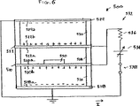
図6に図解された態様では、エネルギー抽出装置500は図示した相互関係の4枚の板518、520、522、524を含む。図6に図解された態様では、エネルギー取得システム502は板522と520を含む。特に、板522と520はカシミール力生成境界として作用する。
【0078】
板520と518は物理的に分離されかつ隔離絶縁器526を介して電気的に絶縁され、板522と520は物理的に分離されかつ隔離絶縁器528を介して電気的に絶縁され、また、板524と522は物理的に分離されかつ隔離絶縁器530を介して電気的に絶縁されている。板522は上方及び下方に可動であり、一方板518、520及び524は非可動である。隔離絶縁器526、528及び530は、酸化シリコンや窒化シリコンのような電気的絶縁材料を含むが、これらに限定されない。
【0079】
エネルギー抽出機器500は、更にエネルギー転換システム532を含む。例示した態様において、エネルギー転換システム532は方法300の操作310Aを実行するように物理的に配列されており、ここでは、カシミール力生成境界を介して取得されたエネルギーは電気エネルギーに転換されて蓄えられる。
【0080】
エネルギー転換システム532は、図示の様に電気的に接続された、板518と524、各板518、520、522及び524に電気的に接続された制御された双方向電源534、スイッチ538及び輻射源540を包含する。ある態様では、輻射源540はレーザの様な単色の輻射源である。
【0081】
輻射源540のような輻射源を介して物理因子が変更され、かつ(1)変更される物理因子が自由荷電担体の濃度であり、また(2)カシミール力生成境界522と520に自由電子担体の生成を補うように不純物がドープされている態様では、輻射源は不純物のイオン化レベルに同調させるのが有利である。輻射源540は制御された電源(図示せず)により動力を供給される。
【0082】
スイッチ538が閉じると、制御された双方向電源534は、板524の側面524aと板522の側面522bで規定される第一の容量構造に、適切に、電荷を注入しかつそれから電荷を受け取るように操作可能である。更に、制御された双方向電源534は、板520の側面520bと板518の側面518aで規定される第二の容量構造に、適切に、電荷を注入しかつそれから電荷を受け取るように操作可能である。
【0083】
図5に示した4枚の板518、520、522及び524の例示的な配置では、各々板524と522の対向した側面524aと522b、及び各々板520と518の対向した側面520bと518aの上に等しく荷電が分布する。導電性でなければならないこれらの側面は、各々板522と520の対向する側面522aと520aが実質的に荷電を受け取ることなく、実質的に全部の荷電を受け取る。これは図5において、板518、520、522及び524の適切な側面に「+」と「−」を置いて図解されている。板524と518は同じ電位に保つのが好ましく、また板522と520は同じ電位に保つのが好ましい。与えられた例示的配列では、板522と520の間の静電力は極めて低く保たれ、それ故無視できる。
【0084】
板522と520は、例えば方法300に準拠して変更されようとしている物理因子に基づいて選択される材料を含む。自由電荷担体の濃度が変更される態様に適した材料は既に説明した。入手可能な参考書、材料、刊行物を用いて、変更される物理因子の関数として材料を適切に選択することは当業者の能力の範囲内である。殆どの場合、材料の選択の確認及び希望に沿って好ましい材料を特定するには、単に実験をするのが有利である。
【0085】
例示した態様において表面522bと520bは導電性であり、またある態様では板522と520は非導電性だから、表面522bと520bに導電性が付与されねばならない。導電性は、例えば、これらの表面を導電性材料(例えばアルミニウム等)で被覆することで付与されよう。板524と518は導電性材料を含む、あるいはある態様では、板上に導電層を堆積させるか板に適切にドープすることにより、導電性が付与される。
【0086】
図6のエネルギー抽出機器500を構成する間隔をおいた板518、520、522及び524の「積み重ね」は、今日当業者に大変なじみ深い技術を用いて形成される。ある態様では、このような伝統的な技術を使用して、何百、何千あるいは何百万の不連続な装置500が一枚の基板上に形成され、与えられた用途の要求に適合する量のエネルギー出力を提供する。
【0087】
一つの態様では、間隔をおいた板の積み重ねは、表面ミクロ機械加工技術を使用して形成される。このような技術の典型は、サンディア国立研究所( HYPERLINK "http://www.mdl.sandia.gov/micromachine/summit5.html" www.mdl.sandia.gov/micromachine/summit5.html)が提供するSUMMiT V技術である。SUMMiT Vは、5水準の多結晶シリコン表面のミクロ機械加工工程である(一の基平面と四の機械的あるいは取り外せる層)。殆どのMEMS(ミクロ電気機械システム:micro electro mechanical systems)成形加工技術と同様、SUMMiT V工程は、薄膜の堆積、フォトリソグラフィーによるフィルムのパターン化及び引き続く化学的エッチングを交互に行うことを包含する。
【0088】
連続する機械的層(すなわちポリシリコン層)は、例えば酸化シリコン層によって分離される。成形加工工程の最後で、二酸化シリコンは化学的に除去され、その際、希望したように多結晶シリコン層を動けるように「解放する」。層の公称の間隔及び及び厚さは以下の通りである。「ポリ0」と識別する第一層は、公称膜厚0.3μmを持つ多結晶シリコンの基平面層である。「ポリ1」と識別する次の層は、膜厚1μmである。ポリ1とポリ0の公称分離距離は2μmである。次の層「ポリ2」は公称膜厚1.5μmで、ポリ1からの公称分離距離は0.5μmである。次の層である「ポリ3」は公称膜厚2.25μmでポリ2からの公称分離距離は2μmである。最後に、「ポリ4」は公称膜厚2.25μmで、ポリ3からの公称分離距離は2μmである。
【0089】
例示のため、SUMMiT V工程を介した図6のエネルギー抽出装置500の成形加工の態様では、ポリ3層は板524を作るように使用され、ポリ2層は板522として使用され、ポリ1層は板520として使用され、そしてポリ0は板518を作るように使用されるであろう。図6の装置では、要求される「機械的」層は3つだけなので、ポリ4層は使用されない。板524と520を不動化するには、層の厚さを大きくすることができるし、あるいはその代わりに適切に固定することができる。
【0090】
装置500のような積み重ね構造の成形加工には、多くの他のMEMS工場を利用できる。当業者はこのような工場を知っているであろうし、またそれらの能力を機器の成形加工に対する要求に合わせて、一の工場を適切に選択することができるであろう。
【0091】
輻射源540は、輻射源の特定の物理的構成(例えばレーザ等)に適切な、よく知られた方法に従って、板518、520、522及び524の積み重ねとは別に形成するのが好ましい。電気素子(例えばスイッチ538、ワイヤトレース等)は、表面のミクロ機械加工工程の一部として積み重ねを形成する間に作ることができるし、これとは別に標準の処理技術でこしらえることができる。次いで種々の要素が完全なエネルギー抽出機器500を形成するように適切にまとめられる。
【0092】
方法のステップ302を実行する前に、スイッチ538が閉じられ、板522は板520からsDの距離で、電位Vbが全ての板にかけられる。教育的な目的で、図2の点Dに対応するこの状態は、システムに関して機械的平衡にあると考えられる。
【0093】
図6は、図2の点Aに対応している、方法のステップ302が完結(すなわち状態変化202が完結)したときの変換器500を図解する。先の説明を思い出して、ステップ302は物理因子Yjの変更を要求する。例示的な態様では、このステップは輻射源540を活性化して遂行する。板520と522中の不純物のイオン化レベルまで輻射源540を運転するのが好ましい。結果として、板520と522の対向するそれぞれの側面520aと522aを照射すると、板520と522中の自由電荷担体の濃度が増大し、そしてそれにより、カシミール力が増大する。
【0094】
照射は、カシミール力の増加が一連の非常に小さい変化として起きるように、ゆっくりと増加させるのが好ましい。エンジンサイクル200に従うと、ステップ302でカシミール力が増加するときに、板522は実質的に静止している。しかし、カシミール力が増加するにつれて、板520と522が互いにより近くに引かれる傾向が現れるであろう。この傾向に反発して、板524と522の間の静電気力は、電位Vbの小さな増加によって増加する。かくして、電源534の正電極に向かう電流として示されているように、電源534から変換器500へ荷電が流れる。ステップ302の完結のときに、輻射源540は点灯したままだが、照射強度は今度は一定に保たれている。
【0095】
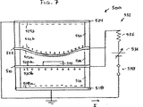
図7は、図2の点Bに対応する、方法のステップ304が完結したとき(すなわち状態変化204の終わり)の変換器500を図解する。図7に図解されている通り、板522は520のより近くへ動いている。板522と520の間の距離のこの減少は、カシミール力を増加させる。板522を板520のより近くに動かすためには、電源534によって加えられる電位を少し減少させる。しかし、板522を擬静止平衡に保つためには、板522と520の間の距離が減少して間隙spに達するまで、荷電が流れ続ける。
【0096】
図8は、図2の点Cに対応する、方法のステップ306が完結したとき(すなわち状態変化206の終わり)の変換器500を図解する。思い出すであろうが、ステップ306では、変更された特性はその元の値に戻るのが好ましい一方、板522と520の間の距離sは実質的に一定に保たれている。例示した態様では、ステップ306は、自由荷電担体の濃度が減少し、それによりカシミール力が減少するように、輻射源540からの照射を減少させることによって実行される。
【0097】
ステップ306の結果としてカシミール力が減少するが、板の間の距離は実質的に一定に保たれるので、過剰の荷電は板524及び522から流出しなければならない。もし流出しないと板522が板524の方向に引かれるので(何故なら、板524と522の間の相互の静電引力が今やカシミール力に起因する板522と520の間の相互引力より大きいから)、過剰の荷電は排出される。図8に例示されている様に、電流は逆になり、エネルギーは双方向電源534に戻される。
【0098】
図9は、サイクル中の点Dに対応する、方法のステップ308が完結したとき(すなわち状態変化208の終わりのとき)の変換器500を図解する。この例においては、点Dで、変換器500は一サイクルを完結する。
【0099】
図9に例示した様に、ステップ308において、板522は板520から引き離されて、好ましくはその元の位置に戻っている。これは、電源534によって伝達される電位を僅かに増加させることにより達成される。板522と520の間の距離が増加すると、カシミール力が減少する。擬静的平衡を維持するように、余分の荷電が板524と522から引き出される。先のステップと同じに、荷電は電源534に戻される。
【0100】
先行の説明を考慮して、例示的サイクル200は、両方ともカシミール力に影響する二つの独立の制御変数の循環運動の見地から説明できることが認められるであろう。かくして、本教示に係る方法600の更に例示的な態様においては(図10を見よ)、カシミール力に影響する第一の制御変数は操作602のように循環され、そして操作604ではカシミール力に影響する第二の制御変数が循環される(すなわちエンジンサイクル200を規定する状態変化202、204、206及び208)。
【0101】
ここに図解した例示的な態様において、第一の制御変数はカシミール力に影響する物理因子を変更し、一方第二の制御変数はカシミール力生成境界の移動を制御する。
【0102】
例として、物理因子が自由荷電担体である態様においては、第一の制御変数は、(1)照射量、(2)熱輻射量、及び(3)注入された荷電量、の例示的な三つの異なる態様をとる。
【0103】
例示的な態様では、電位は第二の制御変数として用いられる。特に、第一の制御変数が物理的パラメータを変更するために使用されるときに(例えば状態変化202と206)、電位は、境界の間の距離を変えるために使用され(例えば状態変化204と208)、あるいは選択的に、境界が動くことを妨げるように使用される。
【0104】
図11aは、エンジンサイクル200中で所望の状態変化を達成するような第一及び第二の制御変数の循環運動を比喩的に図解する。第一の制御変数CV1は第一の値と第二の値の間を循環し、第二の制御変数CV2は第三の値と第四の値の間を循環する。一般的に、各制御変数の循環はある関数、下記FN(T)で表される。
[10] CV1=F1(T)、及び
CV2=F2(T)
二つの制御変数の循環運動は、図11aに図解された円形、あるいは図11b〜10eに示された形のいずれかを定義するために必須ではない。このようなプロットは例示的で、かつ、所望の状態変化を達成するように第一の制御変数CV1と第二の制御変数CV2が循環するであろう多くの可能なやり方の幾つかを単に暗示するものとして提供されている。
【0105】
図11a〜11eにおいて、第一と第二の制御変数は同じ繰り返し速度(すなわち振動数)をもって循環運動をしている。別の態様では、これらの制御変数は異なる繰り返し速度をもって循環する。繰り返し速度が異なる態様において制御変数の循環運動を説明するプロットは、相対的に複雑な関数となるであろう。
【0106】
例示的な態様において、エネルギー転換システム532は、カシミール力生成境界を介して取得したエネルギーを、転換の後、双方向電源534の中に電気エネルギーとして蓄えるように物理的に構成されている。この構成において、エネルギー抽出装置500は方法300の操作310Aを実行している。別の態様では(図示せず)、同じ方法のステップが実行されるが、装置500は分離した電源設備と電力蓄積設備(すなわち転換されたエネルギーを受けるため)を包含する。
【0107】
方法300の別の態様では、操作310Bは、抽出されたエネルギーが電力エネルギーの消費者に使用のために配送される形態で実行される。ある態様では、僅かな修正を伴って(すなわち電気の消費者への適当な電気的結合)、図6〜9に図解したエネルギー転換システム532が適切に使用されるように、エネルギーは貯蔵部から配送される。
【0108】
操作310Bの更に別の態様では、エネルギーは、方法ステップから利用可能になったときに消費者に配送されるので、エネルギー転換システム532は当業者の能力の範囲内にある変化によって適切に修正されなければならない。この態様は、エネルギー抽出機器500が電気的機器650に電気的に接続されている、図11の単純化された模式図に図解されている。カシミール力生成境界を介して取得され電気エネルギーに転換されたエネルギーは、次いで動力機器650に使用される。
【0109】
例示的方法300の更にもう一つ別の態様の操作310Cに準拠して、カシミール力生成境界を介して取得されたエネルギーは、機器を機械的に運転するために使用される。一の態様では、これは、可動のカシミール力生成境界を、機器が可動の境界の動きによって運転されるように、機器に有効に連結することによって達成される。このような態様もまた、エネルギー転換システム532に対して当業者の能力の範囲内である修正を要求するであろう。
【0110】
例えば、図12の単純化した模式図に図解したように、エネルギー抽出機器500は、リンク装置752によってミクロメカニカル機器754に有効に噛み合わされている。ミクロメカニカル機器754は、シャッター758がファイバー760のコア766を通って走る光学的信号の進路(図示せず)に出入りする光学スイッチとして作動する。シャッター758は、板522の動きに応答して、方向756に沿って動く。本方法に応答する板522の動きは、リンク装置752を介してシャッター758に伝達される。
【0111】
シャッター758が光学的信号の進路中にあると(すなわちシャッターがコア766と交叉すると)、それから後の光学的信号の伝播は中止される。シャッター758が光学的信号の進路外にあると、信号の進路は妨げられない。
【0112】
上述した例示的な態様において、相互作用のある二つの面の少なくとも一方の特性を変えるために輻射が使用される(けれどもこのような変化を達成するためには、他のやり方、例えば荷電の注入がある)。更なる態様では、表面と相互作用する粒子の特性を変えるために輻射を使用することができる。事実、後者は、第二の表面が中性原子が極端に少ない層である場合の前者の極限として考えることができる。結果として、表面−表面の力は、単に原子−表面の力の大規模な発現として説明できる。
【0113】
更なる例示的態様は、主に粒子−表面相互作用に基づいて、粒子が加速あるいは減速される方法及び装置を提供する(以下の態様はこのような粒子−表面相互作用に限定されるものではないが)。表面から飛び出した粒子は、それらが表面に接近したときの速度より高いか低いかいずれかの速度で移動させられる。粒子の早さは、それらが表面と相互作用している間に原子遷移を受けさせることにより変えられる。
【0114】
以下の説明において、ファンデルワールス力、カシミール−ポルダー力、ボーア半径、量子数等の概念を引用する。これらの意味は十分に定義され、また当業者はこれらの概念に精通しているので、定義あるいは説明無しでこれらの句を使用する。
【0115】
本技術のある態様に準拠して、基底状態にある原子のような粒子を加速するためには、粒子は表面に接近する途上で「励起」される(すなわちより高いエネルギーレベルへの遷移)。一の態様では、この励起はレーザを使用して達成される。粒子が表面に対して最接近あるいはほぼ最接近すると、それは、次いで好ましくはその基底状態への復帰を誘発される。
【0116】
励起状態における表面への接近の間、粒子と表面の間のファンデルワールス力は非常に高い。基底状態へ復帰した後、粒子と表面の間のファンデルワールス力は実質的に減少する。この引力の減少は、粒子速度の顕著な増大をもたらす。
【0117】
基底状態にある原子のような粒子を減速させるには、粒子を励起するが、励起は表面に最も接近した直後に起こる。このように、いまや励起状態にある外に向かう粒子は、それが基底状態にあって表面の方に向かっていたときよりはるかに高いファンデルワールス力を経験する。この増加した引力は粒子速度を顕著に減少させる。
【0118】
本発明の根底は、粒子が表面と相互作用している間に原子遷移を誘発させて、その出ていく速度(すなわち表面から離れて動くときの速度)を入ってくる速度に対して変えることができるという発見である。この方法はエネルギー保存の原理と一致する。
【0119】
ここに説明した方法と装置は、この40年間ファンデルワールス力を調査するために使用されている、「ラスキン−クッシュの実験」として知られる実験を改良したものである。特に、原子−表面の相互作用を測定するためには、導電性の円筒形表面の近傍に原子線を導いて、ファンデルワールス力に起因する表面からの転向角を測定する。
【0120】
ラスキン−クッシュの実験は、表面との相互作用の間に原子のような粒子が原子遷移を受ける原因とはならない。ラスキン−クッシュの実験における粒子は、表面との相互作用の間に原子遷移を受けるないので、これらは方向を変えるが速度は変えずに表面との相互作用から浮かび出てくる。速度が一定であることは、ファンデルワールス力が保存力として挙動するという事実に起因する。従って、粒子状原子が表面から大きな距離にあるときには、その速度は軌道の入ってくる足にあったときと同じである。
【0121】
本発明の殆どの態様において、加速されている粒子は非常に小さいであろう。種々の態様で使用される小さい粒子の例は、中性原子、中性分子、及び中性素粒子を包含するが、これらに限定されない。けれども、本方法は大きさに無関係に適用される。例えば、ある態様では、ミクロスケールの中性の埃小粒が加速/減速される。もっとずっと大きいスケールでは、直径1フィートの中性の球が本技術に準拠して加速/減速される。けれども、このようなマクロスケールの物体に与えられる加速/減速の量は、原子の大きさの粒子に与えられる量と比較して極めて小さいことが理解されるであろう。一般的に、「粒子」なる語は原子未満、原子、ミクロ及びマクロスケールの物体の全てを包含する。
【0122】
ファンデルワールス及びカシミール−ポルダー力は、関心のある表面に隣接する、例えば原子のような粒子の量子状態に依存する。特に、ファンデルワールス及びカシミール−ポルダー力は、原子のボーア半径の二乗に比例する。そして、ボーア半径は、自身、原子の状態を部分的に説明する主量子数nの二乗に比例する。それ故、ファンデルワールス及びカシミール−ポルダー力は、主量子数の四乗に比例する。
[1] 力∝n4
このnの四乗への依存性は、本発明の背景において重要な関連問題である。例えば、冷たい(cold)原子のような「冷たい」粒子を考える。冷たいと、粒子は通常基底状態にあり、原子の場合、主量子数はn=1である。例えば主量子数がn=10である励起状態にある原子を考える。この場合、励起粒子を表面に引きつけるファンデルワールス力は、式[1]に準拠して、粒子が基底状態にあるときの104倍あるいは10,000倍である。
【0123】
ここで使用する「励起する」あるいは「励起された」という語は、エネルギーの導入に起因して、基底状態より高いエネルギーレベルにある粒子を指す。原子の特別な場合には、励起された原子は1より大きい主量子数を持つであろう。
【0124】
図14は、本発明の例示的な態様に係る粒子加速器800を図解する。粒子加速器800は、図示されたように相関付けられた粒子源802、コリメータ806、粒子励起器814、表面816及び随意に粒子反励起器820を含む。
【0125】
粒子源802は加速器800で加速される粒子を収容する。粒子源802は、非限定的に、熱い気体を収容する炉あるいは原子をトラップし冷却する装置のような、種々のよく知られた機器/システムのどれかとして組み立てることができる。例示的態様では、粒子源802は、粒子源802中の少なくとも幾らかの粒子が流出することを許容するオリフィス804を包含する。ある態様では、オリフィス804は直径約1mmの穴である。
【0126】
流出した粒子801はコリメータ806に衝突する。コリメータ806は、表面816に向いた、方向性の高い粒子ビーム803を提供する。例示した態様において、コリメータ806は、間にスリット812が規定されるように相互に間隔をおいた二枚の板808と810によって実現されている。流出した粒子801をコリメートするスリットあるいは他の開口を提供する配列は、板808と810の代わりに適切に使用できよう。
【0127】
例示した態様において、平行にされた粒子803の少なくとも幾らかは粒子励起器814によって励起される。粒子源802を離れ、コリメータ806を通過する際に、粒子801/803は基底状態|A>にある。粒子励起器814は粒子803の少なくとも幾らかをより高いエネルギー状態|B>に励起する。ある態様では、粒子励起器814は電磁輻射源である。そして、一の具体的な態様では、粒子励起器814は粒子803の遷移エネルギーに合わせて好ましく変調された変調可能なレーザである。
【0128】
励起された粒子805(及び励起されない粒子)は表面816に近づく。表面は、例えば金のような、高度の平坦性に磨くことが可能な物質が好ましい。種々の態様において、表面816は誘電体、半導体及び導体を含む。
【0129】
例示した態様において表面816は円筒形だが、別の態様では、不規則な形状を包含する任意の形状の表面が使用に適する。特定の幾何学に関係なく、表面816は粒子が「極小距離」あるいは「クラスタ」接近(表面への)を許容し、次いで粒子が接触することなく去っていくのを許容することが好ましい。例えば、球の表面あるいは円筒の表面は、表面に、他の部分より粒子の軌道の透視図から突出した場所があるので、このような極小距離の接近あるいは最も近い接近を促進する。この点が極小距離あるいは最接近の場所である。平らな表面(例えば板)は極小距離接近及び流出を容易には許容しないので、使用すべきではない。
【0130】
式[1]を思い出して、励起された粒子805は、励起されない粒子よりも相当程度大きい、表面816へのファンデルワールス引力を経験する。最接近あるいはほぼ最接近818で、励起された粒子805は、フォトンγを放出してそれらの基底状態に減衰する。基底状態への減衰は、自発的減衰により、あるいは随意的な粒子反励起器820を使用する刺激された減衰を介して、起きる。当業者は自発的減衰の時間を予測できるので、自発的減衰は、最接近あるいはほぼ最接近において要求される遷移を引き起こすために当てにできる。
【0131】
ある態様では、粒子反励起器は励起された粒子805に付加的なエネルギーを注入して減衰を刺激する。ある態様では、粒子反励起器820は変調可能なレーザである。
【0132】
基底状態に減衰した後、外へ向かう減衰した粒子807と表面816の間のファンデルワールス引力は、内に向かう励起された粒子805と表面816の間のファンデルワールス引力よりずっと小さい。結果的に、粒子807は、表面816と相互作用した後は、それらが最初に粒子源802を離れたときに較べて、ずっと早く移動するであろう。粒子807の軌道は古典的力学(すなわち散乱理論)を使用して計算できる。
【0133】
本発明の流れの中で、ファンデルワールス力は距離と共に急に低下するので、減衰は、表面への「ほぼ最接近」で起きるに違いない。
[2] 力=−K/R4
ここで、Kは定数、
Rは粒子と表面の間の距離
である。
【0134】
本明細書において、「ほぼ最接近」あるいは「ほぼ極小距離」、「ほぼ極小の接近」あるいは「相互作用の間」という語が基底状態への、あるいはそこからの遷移と共に使用されたときは、粒子が数μm(例えば5μm未満)、好ましくは数百オングストローム以内に最接近している意味である。
【0135】
装置800の効率は、最接近したときに遷移が起きる場合が最高であることに注目してほしい。「ほぼ」最接近の程度で遷移が起きると、効率は幾らか失われる。これは、遷移がほぼしかし最接近する前に起きてもほぼしかし最接近した後に起きても、事実である。
【0136】
この結果−この速度の増加−は、エネルギー保存の原理と矛盾しない。特に、粒子805が減衰するときに放射する電磁輻射エネルギーは、実際に、それが元々吸収したエネルギーより小さい。放射されたエネルギーと吸収されたエネルギーの差は、粒子が表面816に最接近した後の運動エネルギーの増加に正確に等しい。
【0137】
図15に関連して以下に説明する比較的重要でない修正と共に、上述した装置及び方法は粒子を減速するために使用される。図15は本技術に係る粒子減速器を図解する。
【0138】
粒子加速器800と同様に、粒子減速器900は図示されたように相関付けられた粒子源802、コリメータ806、粒子励起器814及び表面816を含む。けれども、減速器900では、粒子加速器800においては最接近の前であるのとは違って、粒子励起器814は最接近の後だがほぼ最接近している818で粒子を励起する。
【0139】
粒子加速器800の場合と同様に、基底状態の粒子801がオリフィス804を通って粒子源802を出て、コリメータ806でコリメートされる。コリメートされた基底状態粒子803は表面816に接近する。表面816に最接近した後だがほぼ最接近している818で、粒子803の少なくとも幾らかは粒子励起器814によって励起される。ある態様では、粒子加速器814は、粒子803の遷移エネルギーに合わせて好ましく変調された変調可能なレーザのような電磁輻射源であるが、これに限定されない。
【0140】
励起された粒子805と表面816の間のファンデルワールス力は、入ってくる基底状態の粒子803と表面816の間のファンデルワールス力よりも大きい。結果として、出ていく励起粒子805は入ってくる粒子803よりも実質的にゆっくりと動いている。
【0141】
励起された粒子805は、ある時期に、フォトンγの放射を伴ってそれらの基底状態へ減衰する(粒子807)。この減衰は最接近からは遠く離れて起こるので、このような減衰は粒子の速度に殆ど影響しない。
【0142】
図16は、本発明の技術に準拠して、正に(すなわち速度を大きくする)あるいは負に(すなわち速度を小さくする)粒子を加速する例示的な方法1000を図解する。操作1002に準拠して、粒子は表面816のような表面に誘導される(図14と15を見よ)。操作1004において、少なくとも幾らかの粒子はより高いエネルギーレベルに励起される。
【0143】
粒子加速器として機能するために、操作1004(すなわち粒子の励起)は表面に最接近する前に実行される。減速を起こさせるため、操作1004は表面に最接近した後だがほぼ再接近であるときに実行される。
【0144】
ある態様では、方法1000は、例えば粒子中により多くのエネルギーを注入することにより、励起された粒子を反励起させる操作1006を包含する。
【0145】
図17は、本発明の技術に準拠して、正に(すなわち速度を大きくする)あるいは負に(すなわち速度を小さくする)粒子を加速する方法1100の択一的態様を図解する。操作1102に準拠して、粒子は表面816のような表面に誘導される(図14及び15を見よ)。操作1104において、少なくとも幾らかの粒子は、表面との相互作用(すなわちほぼ最接近)の間に原子的遷移を促進される。
【0146】
粒子を加速するときに、ある態様では、操作1104は粒子を励起し、次いで例えばエネルギーの付加によって粒子を反励起することを含む。反励起のステップは、ほぼ最接近を生じる。粒子を減速するときに、操作1104は最接近の後だがほぼ最接近において粒子を励起することを含む。
【0147】
粒子加速の方法1200の更なる態様は、図18に関連して以下に説明する。
【0148】
方法1200の操作1202に準拠して、粒子は表面に最接近するように誘導される。操作1204において、粒子が表面へほぼ最接近したとき、粒子と表面の間のカシミール力に影響する表面の物理因子が変更される。カシミール力に影響する物理因子は本明細書で先に説明し、表面の中の自由荷電担体の濃度及び表面を構成する物質の誘電特性を包含するが、これらに限定されない。
【0149】
表面を構成する物質は、変更される物理因子の関数として適切に選択される。例えば、変更される物理因子が自由荷電担体である態様では、物質は好ましくは半導体あるいは化合物半導体である。例示的な半導体(変更される物理因子が自由荷電担体の濃度である態様に関して)は、シリコン(Si)、ゲルマニウム(Ge)であり、及び砒化ガリウム(GaAs)、砒化インジウムガリウム(InGaAs)及びアンチモン化インジウム(InSb)のような化合物半導体を包含するが、これらに限定されない。
【0150】
更に、ある態様では、ドープされた半導体及びドープされた化合物半導体は、自然界にある不純物を含む燐ドープシリコン及びアンチモン化インジウムを包含するが、これらに限定されない。有る態様では、ドーパントはイオン化の相対的な容易性に基づいて選択される。
【0151】
変更される物理因子が自由荷電担体である態様では、変更は、レーザによる表面照射、表面の加熱及び表面内部への荷電の注入を包含する種々のやり方で実施されるが、これらに限定されない。
【0152】
変更される物理因子が自由荷電担体であり、濃度を変更するやり方がレーザを使用する表面照射である態様における方法1200の一例を説明する。
【0153】
粒子が加速される方法1200の一態様において、表面は、粒子がほぼ最接近する前に、レーザで照射される。ほぼ最接近にある粒子は、表面を照射しなかった場合より、カシミール力に起因して相対的により高い引力を受ける。これは、この態様においては、自由荷電担体の濃度の増加に起因する。最接近、あるいは再接近の後だがなおほぼ最接近において、照射は減少されあるいは停止される。これはカシミール力を減少させ、それ故粒子は増加した速度で立ち去る。
【0154】
粒子を減速させるには、照射のタイミングを加速の場合と単に逆転させる。つまり、レーザを最接近、あるいは最接近の後だがほぼ最接近のときに、点灯する。それにより、粒子が最接近から出て行くときにカシミール力は粒子と表面の間でより大きくなり、粒子は減速される。
【0155】
方法1200に含まれるタイミングの問題故に、粒子はパルス形態で表面に届けられなければならないことが判るであろう。言い換えると、例示した方法1200は連続的に流れる粒子を用いては実行できない。
【0156】
別の態様では、方法1000と1200は一緒に使用できるし、方法1100と1200は一緒に使用できる。言い換えると、例えば遷移を起こすように粒子をレーザで照射するのに加えて、粒子を加速あるいは減速するようにカシミール力を使用するため、その上なお表面を照射できる等である。
【0157】
本発明の方法及び装置は、例えば粒子の加熱及び冷却機器、ミクロ推進システム、センサ及びエネルギー変換機器を包含する種々の有用性を見いだしている。
【図面の簡単な説明】
【図1】 よく知られたカシミール力発生システムを図解する。
【図2】 本技術に係る例示的なエンジンサイクルを図解する。
【図3】 本発明の例示された態様に係るエネルギー抽出方法を図解する。
【図4】 板の距離に対するカシミール力の依存性をドーパントレベルの関数として図解する。
【図5】 本技術に係るエネルギー抽出装置の例示的な態様を、比喩的に図解する。
【図6】 図5に図解された例示的なエネルギー抽出装置の一態様を図解する。本装置は、図2の例示的なサイクルに係る第一の状態変化の終期、及び図3の例示的な方法に係る第一ステップの終期において図解されている。
【図7】 図6に示されたエネルギー抽出装置を図解するが、図2の例示的なサイクルに係る第二の状態変化の終期、及び図3の例示的な方法に係る第二ステップの終期における装置を図解する。
【図8】 図6に示されたエネルギー抽出装置を図解するが、図2の例示的なサイクルに係る第三の状態変化の終期、及び図3の例示的な方法に係る第三ステップの終期における装置を図解する。
【図9】 図6に示されたエネルギー抽出装置を図解するが、図2の例示的なサイクルに係る第四の状態変化の終期、及び図3の例示的な方法に係る第四ステップの終期における装置を図解する。
【図10】 10a〜10eは、本技術に係る例示的な方法における二つの制御変数の循環を図解する。
【図11】 本技術に係るエネルギー抽出方法の更なる例示的な態様を図解する。
【図12】 回収されたエネルギーが操作に電気を必要とする機器に使用される際の配列を図解する。
【図13】 回収されたエネルギーが作動力として使用される際の配列を図解する。
【図14】 本発明に係る粒子加速器の例示的な態様を図解する。
【図15】 本発明に係る粒子減速器の例示的な態様を図解する。
【図16】 本発明に係る第一の例示的な粒子の加速/減速方法を図解する。
【図17】 本発明に係る第二の例示的な粒子の加速/減速方法を図解する。
【図18】 本発明に係る第三の例示的な粒子の加速/減速方法を図解する。
【符号の説明】
200・・・エンジンサイクル、202,204,206,208・・・状態変化、300・・・エンジンサイクル200に基づく方法、302・・・第一の操作、410,412,414,416・・・板の距離の関数として表したカシミール力、500・・・エネルギー抽出機器、506・・・双方向インジケータ、518,520,522,524・・・板、520,522・・・カシミール力生成境界、518a,520b,522b,524a・・・板の側面、526,528,530・・・隔離絶縁器、534・・・双方向電源、538・・・スイッチ、540・・・輻射源、752・・・リンク装置、754・・・ミクロメカニカル装置、758・・・シャッター、760・・・ファイバー、766・・・コア、800・・・粒子加速器、801・・・流出した粒子、802・・・粒子源、803・・・粒子ビーム、804・・・オリフィス、805・・・励起された粒子、806・・・コリメータ、808、810・・・板、812・・・スリット、814・・・粒子励起器、816・・・表面、816・・・粒子反励起器、818・・・最接近、900・・・粒子減速器[0001]
[Declaration of related application]
This application claims priority from US Provisional Application 60 / 135,868, filed May 25, 1999.
[0002]
FIELD OF THE INVENTION
The present invention relates generally to the extraction of energy from a force field source such as a quantum electromagnetic field.
[0003]
BACKGROUND OF THE INVENTION
300 years ago, it was believed that if all the material was removed from the spatial domain, it would become a completely empty volume, ie a vacuum. 100 years ago, if all material was removed from a spatial region, it was known that that region was still not empty because it still contained thermal radiation. However, at that time, it was mistakenly believed that a vacuum could still be created by removing the heat radiation by cooling the space to absolute zero.
[0004]
More recently, the theory predicts that non-thermal radiation exists everywhere in the universe, even in the absence of matter and thermal radiation, and experiments have demonstrated. This non-thermal radiation is believed to be the result of random fluctuations that occur at the quantum level and are constantly creating and destroying virtual particles. This radiation is often referred to as “ZPF” by “zero point field” or acronym, and the energy associated with this field is simply called “ZPE” by “zero point energy”, “vacuum energy” or acronym.
[0005]
In 1948, Hendrik BJ Casmir theorizes that two completely conductive and neutral surfaces placed in parallel with each other induce mutual attraction did. This force has since been called the “Kashmir force” and arises from the effect these two surfaces have on the vacuum energy of the source field, such as the electromagnetic field between these surfaces.
[0006]
It is believed that the Kashmir force comes from the quantum level of activity described above. The presence of two sides of Kashmir, or practically two plates, limits the permissible modes of random fluctuation oscillations in a quantum electromagnetic field. In other words, the presence of the plate changes the boundary condition of the electromagnetic field from the free field condition. As a result, the vacuum electromagnetic field energy density in the space between these plates is less than the energy density outside this space (i.e., the number of virtual particles per unit volume in the space between the plates is the unit outside this space. Less than the number of virtual particles per volume). This energy density difference or slope causes a force to press the plates together (ie, Kashmir force).
[0007]
Although the Kashmir force is “real” in that it can be observed, the quantum electrodynamic (“QED”) theory described above is not the only theory that fully explains its existence. In particular, stochastic electrodynamics (“SED”) provides another interpretation, but yields the same prediction.
[0008]
Kashmir force F per unit areacIs given by the following equation.
[1] FC(S) = (π2/ 240) ・ (h'c / sFour)
Where ・ means “multiplication”,
h ′ = h / (2π),
h is Planck's constant,
c is the speed of light in vacuum,
s is the distance between the two conductive surfaces,
It is.
[0009]
From equation [1], when s approaches zero, Kashmir force FCIt is clear that (s) becomes large. In fact, the Kashmir force per unit area between two plates separated by a distance s of about 0.1 μm is the electrostatic force per unit area that acts between the same two plates in the presence of a potential difference of about 100 millivolts. Equivalent to.
[0010]
ZPE is expected to exhibit an infinite energy density and to exist universally and therefore would be an infinite energy source. This is not surprising, but has led to a number of efforts to frustrate researchers and devote themselves to ZPE research and commercialization. Despite such efforts, researchers have not yet developed an apparatus and method suitable for commercial use of ZPE.
[0011]
SUMMARY OF THE INVENTION
In one aspect of the method according to the present invention, an engine cycle is defined that includes a number of state changes that allow for a net increase or recovery of energy acquired via a Kashmir force generation boundary (eg, a plate, etc.).
[0012]
An exemplary aspect of the energy conversion / recovery method according to the present teachings includes the following steps.
[0013]
Changing a physical factor affecting the Kashmir force between two separated Kashmir force generation boundaries;
Changing the separation distance between two separated Kashmir force generation boundaries;
Changing the physical factor again to return the physical factor to its previous value; and
Returning the separation distance between the boundaries to the original value;
[0014]
In one aspect of the exemplary method, the physical factor that is changed is the concentration of free charge carriers in the Kashmir force generation boundary. One way to change the concentration of free charge carriers is to irradiate at least one Kashmir force generation boundary (ie, a plate) with photons. Another way is to raise the temperature of such a boundary, and yet another way is to inject charge into at least one Kashmir force generation boundary.
[0015]
In certain aspects, an exemplary method includes storing energy obtained via a Kashmir force generation boundary after being appropriately deformed. In another aspect, the method includes allocating energy acquired via the Kashmir force generation boundary to another electrical consumer after appropriate conversion. In yet another aspect, the method includes actuating a micromechanical device using energy acquired via the Kashmir force generation boundary.
[0016]
An exemplary apparatus for performing the method of the present invention, in one aspect, includes a zero point energy acquisition system (eg, two Kashmir force generation boundaries) operatively coupled to the energy conversion system. In certain aspects, the energy conversion system includes a first device that can be used to change at least one physical factor of the system and a second device that can be used to change the distance between the Kashmir force generation boundaries. To do. The first and second devices preferably operate independently of each other so that the physical factors can be affected simultaneously and the spacing between the boundaries can be controlled.
[0017]
The structure of the energy conversion system varies as a function of the nature of the energy conversion (eg, conversion into electrical energy for storage, electrical energy for direct use, mechanical / mechanical energy for operation, etc.).
[0018]
The basis of the exemplary engine cycle, method and apparatus described herein is that the Kashmir force system can change one or more physical factors appropriately, or one or more environmental factors that affect such physical factors. It is a discovery that it can be made non-conservative by changing.
[0019]
More specifically, by changing the physical factors that affect the Kashmir force, create a device that consumes more energy when the Kashmir force generation boundary is pulled than when the Kashmir force generation boundary is pulled apart. It was discovered that it was possible. As a result, when such boundaries are pulled apart, net energy transfer occurs. This cycle can be repeated as long as the device persists.
[0020]
Unlike gravity, whose value does not depend on the properties of the mass applied, the Kashmir force depends on various physical factors that can be changed if a special energy price is paid. If such a material is in absolute value less than the total work done by the Kashmir force during a cycle, the net amount of energy obtained through the Kashmir force generation boundary can be used for recovery. If the fee is in absolute value greater than the total work done by the Kashmir force in a cycle, then the method and apparatus will simply operate to convert energy (ie, as a converter) The net gain of is not produced.
[0021]
Some aspects of the present invention seem to contradict the typical interpretation of the principle of energy conservation, but in practice do not contradict it. The energy obtained via the Kashmir force generation boundary is made available because of the well-known energy conservation argument, not contrary to these.
[0022]
As mentioned in the “Background” section, (at least in one interpretation) the Kashmir force is a boundary condition for source forces such as quantum electromagnetic fields, “strong” force fields, gravity fields, and “weak” force fields. It is generated by applying a load. Although the exemplary methods and apparatus described herein are directed to systems where the Kashmir force is generated by interaction with a quantum electromagnetic field, the present invention is directed to a force field, a gravity field, and a “weak” Kashmir force. It can also be applied to systems caused by interaction with force fields.
[0023]
It will be understood that exemplary aspects of the invention do not literally “convert” or “convert” zero point energy to another form of energy. In particular, in certain aspects of an exemplary apparatus according to the present invention, the Kashmir force generation boundary interacts or interacts with the energy conversion system. Such interactions include, for example, moving a linkage that engages another device or affecting the electrostatic field. As long as such an interaction occurs, the zero point energy is thus converted or converted to another form of energy, whether electrical, mechanical or the like.
[0024]
In this specification, the phrase “kashmir force generation boundary” can limit the permissible vibration modes of random quantum level fluctuations of the source force field, or else the boundary condition of the source force field from the free field condition. Any object (mass) or force field that can be changed. Such objects include, but are not limited to plates, spheres, particles (even atoms and even sub-atomic particles), and the like. For force fields, any secondary force field, including the electromagnetic field (ie, secondary for the source force field) interacts with the source force field, thus changing the boundary conditions of the source force field from the free field conditions However, it is not limited to these.
[0025]
In this specification, the phrase “energy acquired through the Kashmir force generation boundary” means energy (for example, zero point energy) generated from a source force field (for example, a quantum electromagnetic field, etc.) operated through Kashmir force. .
[0026]
In this specification, when the terms “net gain”, “net exchange”, and the term “recovery” are used in combination with the term “energy”, more energy is added to the energy added thereto. Means being pulled from the system. When the phrase “convert” or “convert” is used in combination with the word “energy”, the energy obtained via the Kashmir force generation boundary is available for use, but via this method or device. Means that no net gain of energy is realized. In this specification, the term “extraction” used in combination with the term “energy” is broadly meant to refer to both energy conversion and energy recovery, or one of energy conversion and energy recovery.
[0027]
The exemplary embodiment described herein is an improvement on the simple and well-known kashmir force generation system illustrated in FIG. In particular, FIG. 1 shows two Kashmir force generation boundaries P1And P2Is illustrated. Kashmir force generation boundary P1And P2Are separated by a distance s. Kashmir force generation boundary P1Is the Kashmir force generation boundary P2It is movable towards (and away from).
[0028]
As will be appreciated by those skilled in the art, when performing Kashmir force calculations, the Kashmir force generation boundary P1And P2Is considered a “semi-infinite” thick plate (typically a dielectric). Thus, in this calculation, the Kashmir force generation boundary P1(Shown as a thin plate-like structure in FIG. 1) is the boundary P2P close to1It is assumed that it starts from the surface and extends to the left (in FIG. 1) indefinitely. Similarly, Kashmir force generation boundary P2Is the boundary P1P close to2Starting from the surface of, it extends to infinity to the right.
[0029]
Semi-infinite boundary P1Is the dielectric property ε1A semi-infinite boundary P with (ω)2Is the dielectric property ε2Has (ω). The region between these boundaries is the dielectric property ε3Is assumed to have (ω). When performing a quantitative assessment, usually ε1(Ω) = ε2(Ω) and ε3Assume that (ω) = 1. Of course, real boards do not have infinite thickness. In many cases, the non-infinite thickness of a real plate does not change the quantitative results that rely on the assumption of a semi-infinite boundary.
[0030]
It will be appreciated that the Kashmir force is a function of the specific geometry of the Kashmir force generation system. For example, in a system that includes two parallel boundaries as shown in FIG. 1, the Kashmir force is attractive, whereas in a system that includes two hemispheres of a thin metal spherical shell, the Kashmir force is a repulsive force. In addition, spaced boundary P1And P2Changing the physical orientation of the material from “parallel” to “non-parallel” will affect the Kashmir force. And of course, changing the angle defined by two non-parallel boundaries will change the Kashmir force. Also, bending one boundary (see, eg, FIG. 6) will affect the Kashmir force. The ability to extract energy according to the present teachings, and the magnitude of such extraction, can therefore vary as a function of the particular sequence used. One skilled in the art will appreciate that aspects of the present invention can use Kashmir force generation boundaries arranged in many unique arrangements other than the spaced parallel relationship illustrated in FIG.
[0031]
Referring again to FIG.1And P2Kashmir force F duringCIs
1. The distance s between the surfaces,
2. The material that forms the system (eg boundary P1And P2Any physical factor Y that determines the dielectric and other properties (eg surface roughness, etc.)j,
3. Each physical factor YjEnvironmental factors that affectj,
It is illustrated as an attraction that is a function of.
[0032]
For
[0033]
For term 3, the physical factor YjFactor X affectingjIncludes but is not limited to absolute temperature and radiation density. And physical factor YjIs dependent on Kashmir force FCTo any inherent dependence on temperature. Thus, P1And P2Kashmir force F for any given arrangement ofCIs
[2] FC= FC(s; Y1(X1, X2, ...); Y2(X1, X2, ・ ・ ・ ・); ・ ・ ・ ・)
It is a kind of function.
[0034]
FIG. 2 illustrates a plot of an exemplary “engine”
[0035]
In FIG. 2, the horizontal axis (that is, the x-axis) represents two Kashmir force generation boundaries P1And P2(See FIG. 1), the vertical axis (ie y-axis) is the Kashmir force FCIndicates the absolute value of.
[0036]
The
[0037]
The
[3] FC A= FC(sA; Y1A(X1A, X2A, ...); Y2 A(X1A, X2A, ・ ・ ・ ・); ・ ・ ・ ・)
A state change or
[4] FC B= FC(sB; Y1A(X1A, X2A, ...); Y2 A(X1A, X2A, ・ ・ ・ ・); ・ ・ ・ ・)
It becomes. In the
[0038]
At point B, another state change occurs, which ends at point C. As illustrated in FIG. 2, during the state change 206 (ie, B → C), the Kashmir force generation boundary (eg, P1And P2) Is held substantially constant so that there is no change in the distance between them. Instead, physical factor Yj(Xj). By definition, such a physical factor affects the Kashmir force, so the physical factor Yj(Xj) Change is Kashmir force FCThe value of
[5] FC C= FC(sB; Y1C(X1C, X2C, ...); Y2 C(X1C, X2C, ・ ・ ・ ・); ・ ・ ・ ・)
And In equation [5], the distance s has no change in this variable during the state change 206 (ie sC = sB) To emphasize that “sBIs expressed.
[0039]
[6] FC D= FC(sA; Y1C(X1C, X2C, ...); Y2 C(X1C, X2C, ・ ・ ・ ・); ・ ・ ・ ・)
It is.
[0040]
Finally, in the
[7] FC A= FC(sA; Y1A(X1A, X2A, ...); Y2 A(X1A, X2A, ・ ・ ・ ・); ・ ・ ・ ・)
Given in.
[0041]
Total energy W available from
[8] Wnet= (WDA-WBC-WCm
here,
WBCIs the amount of energy converted from the system to create state change 206 (WBC> 0)
WDAIs the amount of energy converted into the system to create state change 202 (WDA<0) and
WCmKashmir force FCIs the total mechanical work (ie, the area enclosed by the curve defining cycle 200) done for that closed path.
[0042]
Amount WDAAlternatively,
[0043]
Work W done with Kashmir powerCmIs given by equation [9].
![]()
Traditional energy conversion systems are conservative. As such, the total energy W obtained from such a system.netIs zero. In other words, the energy “from” such a system is never greater than the energy added to such a system. In actual systems, considering inefficiencies (such as friction), the useful energy from a system is generally much less than the energy added to the system.
[0045]
Consider a hydropower plant as an example. You cannot return water to the top of the waterfall without consuming exactly the same amount of kinetic energy that you get at the bottom of the waterfall when the same amount of water falls through the turbine. This can be fully understood from the nature of conservation of gravity. Indeed, a considerable amount of experimentation has consistently shown that the constant of gravity is independent of the chemistry of the material involved and its temperature.
[0046]
In contrast to the gravitational constant, every theory of Kashmir force between two surfaces predicts just a dependence on physical or environmental factors (see equation [2] above). Therefore, a climate that compares the exchange of energy acquired through the Kashmir force generation boundary to the replacement of hydropower energy production and other traditional energy production schemes is inappropriate and inaccurate.
[0047]
The inventor has the physical factor Yj(Xj) Can be made non-conserving by appropriate modification, and at least theoretically, the net exchange of energy obtained through the Kashmir production boundary, as through the
[0048]
However, considering the cycle, the potential for energy recovery is obvious. The
[0049]
The difference in work described above can be seen in FIG. In particular, the change in the Kashmir force is such that the distance of the plate decreases, the change in the state from point A to point B (work done by the Kashmir force) increases the plate distance, from point C to point D. Greater than the state change (energy is supplied to pull the plate apart). Again, it is the physical factor Y that makes this possiblej(Xj) Value change.
[0050]
Specifically, at points A and B, the physical factor is defined by a first set of values (see equations [3] and [4]), while at points C and D, the physical factor has a second value. Defined by a pair (see equations [5] and [6]). Kashmir force is physical factor Yj(XjTherefore, when the value of the physical factor changes, there is a difference in the Kashmir force for a given distance between the Kashmir force generation boundaries (eg, compare point D with point A). And more importantly in the flow of the present invention, the rate of change of the Kashmir force is different.
[0051]
The recovery of energy from the source energy field, according to the
[0052]
Again, unlike gravity, it depends on various physical factors that can change the Kashmir force if special energy prices are paid. If such a fee is in absolute value less than the work done by the Kashmir force of
[0053]
This finding seems to contradict the typical considerations of the principle of energy conservation. The fact is not so. The energy acquired through the Kashmir force generation boundary is made available for well-known energy conservation discussions and should not be ignored. In practice, in the
[0054]
Despite what has been said so far, if due to technical or other unexpected limitations, the net gain of energy obtained through the Kashmir force generation boundary cannot be realized, then the
[0055]
FIG. 3 is a flow diagram of an exemplary method 300 for extracting energy acquired via a Kashmir force generation boundary, in accordance with aspects of the present invention. Method 300 is based on
[0056]
The method 300, like the
[0057]
Referring to FIG. 3, in a
[0058]
Examples of physical factors that are altered in various aspects include, but are not limited to, the concentration of free charge carriers and the location and strength of any absorption band in the material that forms the Kashmir force generation boundary. In another aspect, the physical factor that is altered includes the material properties of the Kashmir force generation boundary. Such material properties include, but are not limited to, dielectric properties and surface roughness.
[0059]
Further changeable physical factor YjEncompasses the specific geometry of the Kashmir force generation boundary system. For example, the separated boundary P1And P2Changing the physical orientation of the material from “parallel” to “non-parallel” will affect the Kashmir force. And, of course, changing the angle defined by the two non-parallel boundaries will change the Kashmir force. Also, bending the boundary (see, eg, FIG. 6) will affect the Kashmir force.
[0060]
The material constituting the Kashmir force generation boundary is the physical factor Y that is selected for changejIs appropriately chosen as a function of For example, when the physical factor to be changed is a free charge carrier, the boundary is preferably a semiconductor or a compound semiconductor. Exemplary semiconductors (in the embodiment where the physical factor being modified is a free charge carrier) are silicon (Si), germanium (Ge), and gallium arsenide (GaAs), indium gallium arsenide (InGaAs), and indium antimonide. Including, but not limited to, compound semiconductors such as (InSb).
[0061]
Further, in some embodiments, the boundary includes a doped semiconductor and a doped compound semiconductor. These include, but are not limited to, phosphorous doped silicon and indium antimonide, including naturally occurring impurities. In some embodiments, the dopant is selected based on relative ionization ease.
[0062]
By way of example, FIG. 4 illustrates a plot showing the change in Kashmir force due to the change in free charge carrier concentration achieved with various dopant concentrations.
[0063]
In some embodiments,
[0064]
In another aspect,
[0065]
As used herein, the phrase “modifying the physical factor” refers to the physical factor Y as described above.jFactor X affectingjBy changing the physical factor YjPhysical factor Y with indirect change ofjIt is meant to cover both direct changes. As used herein, the phrase “changing physical factors” is the Kashmir force generation boundary P1And P2It is explicitly excluded to change the distance between. Further, unless otherwise indicated, the phrase “physical factor” is meant to include physical factors and environmental factors that affect physical factors.
[0066]
Continuing with the description of the exemplary method 300, two Kashmir force generation boundaries P1And P2The distance s between is changed in
[0067]
One or more physical factors Y changed in
[0068]
In another aspect, the physical factors that are changed are changed to the appropriate “direction”, but do not return to their original values. For example, referring to FIG. 2, in another aspect, the physical factor is changed so that the Kashmir force decreases, as in the B → C transition, but the physical factor does not return to its original value, The change does not reduce the Kashmir force sufficiently to the value at point C. Rather, this state change causes the Kashmir force to be greater or less than the value at point C. In yet another aspect, in operation 306, a physical factor different from that changed in
[0069]
In operation 308, the two boundaries P1And P2The distance s between is again changed. In particular, it is preferable to return the movable surface to its original position. Thus, when operation 308 is completed, the distance s between the boundaries is preferably the same as before the boundary was moved in
[0070]
The exemplary method 300 is further described later in this specification with reference to FIGS. 6-11 illustrating one aspect of an exemplary energy extraction apparatus 500 (see FIG. 5) that performs the exemplary method 300. explain.
[0071]
The
[0072]
The
[0073]
The
[0074]
In an exemplary aspect, the
[0075]
In an exemplary embodiment, the
[0076]
The particular physical arrangement of the
[0077]
In the embodiment illustrated in FIG. 6, the
[0078]
[0079]
The
[0080]
The
[0081]
The physical factor is changed via a radiation source, such as
[0082]
When
[0083]
In the exemplary arrangement of the four
[0084]
[0085]
In the illustrated embodiment, surfaces 522b and 520b are conductive, and in certain embodiments,
[0086]
The “stack” of spaced
[0087]
In one embodiment, the stack of spaced plates is formed using surface micromachining techniques. A typical example of such technology is Sandia National Laboratory (HYPERLINK "http://www.mdl.sandia.gov/micromachine/summit5.html"www.mdl.sandia.gov/micromachine/summit5.htmlSUMMiTV technology provided by SUMMiT V is a micro-machining process of 5 levels of polycrystalline silicon surface (one ground plane and four mechanical or removable layers). Like most MEMS (micro electro mechanical systems) molding techniques, the SUMMiTV process involves alternating thin film deposition, photolithography film patterning, and subsequent chemical etching.
[0088]
Successive mechanical layers (ie polysilicon layers) are separated by, for example, silicon oxide layers. At the end of the molding process, the silicon dioxide is chemically removed, in which it “releases” the polycrystalline silicon layer so that it can move as desired. The nominal spacing and thickness of the layers are as follows: The first layer, identified as “Poly 0”, is a ground plane layer of polycrystalline silicon having a nominal film thickness of 0.3 μm. The next layer, identified as “
[0089]
For purposes of illustration, in the molding aspect of the
[0090]
Many other MEMS factories can be used to form stacked structures such as the
[0091]
The
[0092]
Prior to performing
[0093]
FIG. 6 illustrates
[0094]
Irradiation is preferably increased slowly so that the increase in Kashmir force occurs as a series of very small changes. According to
[0095]
FIG. 7 illustrates
[0096]
FIG. 8 illustrates the
[0097]
As a result of step 306, the Kashmir force is reduced, but the distance between the plates remains substantially constant so that excess charge must flow out of
[0098]
FIG. 9 illustrates
[0099]
As illustrated in FIG. 9, at step 308, the
[0100]
In view of the preceding description, it will be appreciated that the
[0101]
In the exemplary embodiment illustrated here, the first control variable changes the physical factor that affects the Kashmir force, while the second control variable controls the movement of the Kashmir force generation boundary.
[0102]
By way of example, in an embodiment where the physical factor is a free charge carrier, the first control variables are three exemplary variables: (1) irradiation dose, (2) thermal radiation dose, and (3) injected charge dose. Take two different aspects.
[0103]
In an exemplary embodiment, the potential is used as the second control variable. In particular, when the first control variable is used to change a physical parameter (eg, state changes 202 and 206), the potential is used to change the distance between the boundaries (eg,
[0104]
FIG. 11 a illustrates figuratively the cyclic motion of the first and second control variables to achieve the desired state change in the
[10] CV1 = F1(T), and
CV2 = F2(T)
The circular motion of the two control variables is not essential to define either the circle illustrated in FIG. 11a or the shape shown in FIGS. 11b-10e. Such a plot is exemplary and merely suggests some of the many possible ways that the first control variable CV1 and the second control variable CV2 would cycle to achieve the desired state change. It is provided as something to do.
[0105]
In FIGS. 11a to 11e, the first and second control variables are circulated at the same repetition rate (ie, frequency). In another aspect, these control variables circulate with different repetition rates. A plot describing the cyclic motion of the control variable in a manner with different repetition rates will be a relatively complex function.
[0106]
In the exemplary embodiment,
[0107]
In another aspect of method 300,
[0108]
In yet another aspect of
[0109]
In accordance with yet another aspect of operation 310C of the exemplary method 300, the energy obtained via the Kashmir force generation boundary is used to mechanically operate the device. In one aspect, this is accomplished by effectively coupling the movable Kashmir force generation boundary to the device such that the device is driven by the movement of the movable boundary. Such an embodiment would also require modifications to the
[0110]
For example, as illustrated in the simplified schematic diagram of FIG. 12, the
[0111]
If the shutter 758 is in the path of the optical signal (ie, when the shutter crosses the core 766), then subsequent optical signal propagation is stopped. If the shutter 758 is outside the path of the optical signal, the path of the signal is not hindered.
[0112]
In the exemplary embodiment described above, radiation is used to change the properties of at least one of the two interacting surfaces (although to achieve such a change, other methods such as charge injection are used. There is). In a further aspect, radiation can be used to alter the properties of particles that interact with the surface. In fact, the latter can be considered as the limit of the former when the second surface is a layer with extremely few neutral atoms. As a result, surface-surface forces can be described simply as large scale manifestations of atom-surface forces.
[0113]
Further exemplary embodiments provide methods and apparatus in which particles are accelerated or decelerated primarily based on particle-surface interactions (the following embodiments are not limited to such particle-surface interactions). Not) Particles that jump out of the surface are moved at a speed that is either higher or lower than when they approach the surface. The speed of the particles can be changed by subjecting them to atomic transitions while they interact with the surface.
[0114]
In the following description, concepts such as van der Waals force, Kashmir-Polder force, Bohr radius, quantum number, etc. are cited. These meanings are well defined and those skilled in the art are familiar with these concepts, so these phrases are used without definition or explanation.
[0115]
In accordance with certain aspects of the present technology, to accelerate a particle, such as an atom in the ground state, the particle is “excited” (ie, transitions to higher energy levels) on the way to the surface. In one aspect, this excitation is achieved using a laser. When the particle is closest or nearly closest to the surface, it is then preferably triggered to return to its ground state.
[0116]
During access to the surface in the excited state, the van der Waals force between the particle and the surface is very high. After returning to the ground state, the van der Waals force between the particle and the surface is substantially reduced. This decrease in attractive force results in a significant increase in particle velocity.
[0117]
To decelerate a particle, such as an atom in the ground state, the particle is excited, which occurs immediately after it is closest to the surface. Thus, an outgoing particle now in an excited state will experience a much higher van der Waals force than when it was in the ground state and towards the surface. This increased attractive force significantly reduces the particle velocity.
[0118]
The basis of the present invention is to induce an atomic transition while the particle is interacting with the surface, changing its exiting speed (ie the speed when moving away from the surface) relative to the incoming speed. It is a discovery that can be done. This method is consistent with the principle of energy conservation.
[0119]
The method and apparatus described here is an improvement on an experiment known as the “Ruskin-Kush Experiment” that has been used to investigate van der Waals forces for the last 40 years. In particular, in order to measure the atom-surface interaction, an atomic beam is guided in the vicinity of the conductive cylindrical surface, and the turning angle from the surface due to van der Waals force is measured.
[0120]
Ruskin-Kush experiments do not cause particles such as atoms to undergo atomic transitions during interaction with the surface. Since the particles in the Ruskin-Kush experiment do not undergo atomic transitions during the interaction with the surface, they emerge from the interaction with the surface without changing the speed but with the velocity. The constant speed is due to the fact that van der Waals forces behave as conservatives. Thus, when the particulate atom is at a large distance from the surface, its velocity is the same as when it was on the orbiting foot.
[0121]
In most embodiments of the invention, the particles being accelerated will be very small. Examples of small particles used in various embodiments include, but are not limited to, neutral atoms, neutral molecules, and neutral particles. However, the method is applied regardless of size. For example, in certain embodiments, microscale neutral dust particles are accelerated / decelerated. At much larger scales, a neutral sphere of 1 foot in diameter is accelerated / decelerated according to the present technology. However, it will be appreciated that the amount of acceleration / deceleration imparted to such macro-scale objects is very small compared to the amount imparted to atomic size particles. In general, the term “particle” encompasses all sub-atomic, atomic, micro and macro scale objects.
[0122]
Van der Waals and Kashmir-Polder forces depend on the quantum state of particles, such as atoms, adjacent to the surface of interest. In particular, van der Waals and Kashmir-Poulder forces are proportional to the square of the atomic Bohr radius. The Bohr radius is proportional to the square of the main quantum number n that partially explains the state of the atom itself. Therefore, van der Waals and Kashmir-Poller forces are proportional to the fourth power of the main quantum number.
[1] Power4
This dependence of n on the fourth power is an important related issue in the context of the present invention. For example, consider a “cold” particle, such as a cold atom. When cold, the particles are usually in the ground state, and in the case of atoms, the main quantum number is n = 1. For example, consider an atom in an excited state whose main quantum number is n = 10. In this case, the van der Waals force that attracts the excited particles to the surface is 10 according to the equation [1] when the particles are in the ground state.4Double or 10,000 times.
[0123]
As used herein, the terms “excited” or “excited” refer to particles that are at a higher energy level than the ground state due to the introduction of energy. In the special case of atoms, the excited atom will have a principal quantum number greater than one.
[0124]
FIG. 14 illustrates a particle accelerator 800 according to an exemplary aspect of the present invention. The particle accelerator 800 includes a particle source 802, a
[0125]
Particle source 802 contains particles that are accelerated by accelerator 800. The particle source 802 can be assembled as any of a variety of well-known equipment / systems such as, but not limited to, a furnace containing hot gas or an apparatus for trapping and cooling atoms. In the exemplary embodiment, particle source 802 includes an orifice 804 that allows at least some of the particles in particle source 802 to flow out. In some embodiments, the orifice 804 is a hole having a diameter of about 1 mm.
[0126]
The
[0127]
In the illustrated embodiment, at least some of the collimated particles 803 are excited by a
[0128]
Excited particles 805 (and unexcited particles) approach surface 816. The surface is preferably a material that can be polished to a high degree of flatness, such as gold. In various aspects, the surface 816 includes a dielectric, a semiconductor, and a conductor.
[0129]
In the illustrated embodiment, the surface 816 is cylindrical, but in other embodiments, any shaped surface is suitable for use, including irregular shapes. Regardless of the particular geometry, the surface 816 preferably allows the particles to “minimum distance” or “cluster” approach (to the surface) and then leave the particles without contact. For example, the surface of a sphere or the surface of a cylinder facilitates such a close or closest approach because there are places on the surface that protrude beyond the perspective of the particle trajectory from other parts. This point is the minimum distance or the closest place. A flat surface (eg, a plate) should not be used because it does not readily allow for close range access and outflow.
[0130]
Recalling equation [1], the
[0131]
In some embodiments, the particle anti-exciter injects additional energy into the
[0132]
After attenuation to the ground state, the van der Waals attraction between the outwardly attenuated particle 807 and the surface 816 is much less than the van der Waals attraction between the inward
[0133]
In the course of the present invention, the van der Waals force decreases rapidly with distance, so the damping must occur “nearly close” to the surface.
[2] Force = -K / R4
Where K is a constant,
R is the distance between the particle and the surface
It is.
[0134]
In this specification, when the terms "almost closest" or "almost minimal distance", "almost minimal approach" or "during interaction" are used with a transition to or from the ground state, This means that the particles are closest within a few μm (for example, less than 5 μm), preferably within a few hundred angstroms.
[0135]
Note that the efficiency of the device 800 is best when a transition occurs when closest. Some efficiency is lost when the transition occurs at a "near" closest degree. This is true whether the transition occurs almost but before the closest or almost but after the closest.
[0136]
This result-this increase in speed-is consistent with the principle of energy conservation. In particular, the electromagnetic radiation energy emitted when the
[0137]
With the relatively unimportant modifications described below in connection with FIG. 15, the apparatus and method described above are used to decelerate particles. FIG. 15 illustrates a particle reducer according to the present technology.
[0138]
Similar to particle accelerator 800,
[0139]
As with the particle accelerator 800, the
[0140]
The van der Waals force between the
[0141]
[0142]
FIG. 16 illustrates an
[0143]
To function as a particle accelerator, operation 1004 (ie, particle excitation) is performed before the surface is closest. To cause deceleration,
[0144]
In an aspect, the
[0145]
FIG. 17 illustrates an alternative embodiment of a
[0146]
When accelerating a particle, in one aspect, operation 1104 includes exciting the particle and then de-exciting the particle, for example, by the addition of energy. The anti-excitation step results in a near-close approach. When decelerating the particles, operation 1104 includes exciting the particles after the closest approach but at approximately the closest proximity.
[0147]
Further aspects of the particle acceleration method 1200 are described below in connection with FIG.
[0148]
Consistent with
[0149]
The material constituting the surface is appropriately selected as a function of the physical factor to be changed. For example, in embodiments where the physical factor to be changed is a free charge carrier, the material is preferably a semiconductor or a compound semiconductor. Exemplary semiconductors (for embodiments where the physical factor being altered is the concentration of free charge carriers) are silicon (Si), germanium (Ge), and gallium arsenide (GaAs), indium gallium arsenide (InGaAs), and antimony. Including, but not limited to, compound semiconductors such as indium phosphide (InSb).
[0150]
Further, in some embodiments, doped semiconductors and doped compound semiconductors include, but are not limited to, phosphorous-doped silicon and indium antimonide containing natural impurities. In some embodiments, the dopant is selected based on the relative ease of ionization.
[0151]
In embodiments where the physical factor to be modified is a free charge carrier, the modification can be performed in a variety of ways including, but not limited to, surface irradiation with a laser, surface heating, and injection of charge into the surface.
[0152]
An example of a method 1200 in an embodiment where the physical factor to be changed is a free charge carrier and the manner of changing the concentration is surface irradiation using a laser is described.
[0153]
In one aspect of the method 1200 in which the particles are accelerated, the surface is irradiated with a laser before the particles are nearly closest. Nearly closest particles will receive a relatively higher attractive force due to the Kashmir force than if the surface was not irradiated. This is due to an increase in the concentration of free charge carriers in this embodiment. Irradiation is reduced or stopped after the closest or re-approximation but still at the closest proximity. This reduces the Kashmir force, so the particles leave at an increased rate.
[0154]
To decelerate the particles, the irradiation timing is simply reversed from that for acceleration. That is, the laser is turned on when it is closest or after the closest approach. Thereby, the Kashmir force is greater between the particle and the surface as the particle leaves the closest approach and the particle is decelerated.
[0155]
It will be appreciated that due to the timing issues involved in the method 1200, the particles must be delivered to the surface in pulsed form. In other words, the illustrated method 1200 cannot be performed using continuously flowing particles.
[0156]
In another aspect,
[0157]
The methods and apparatus of the present invention find a variety of utilities including, for example, particle heating and cooling equipment, micropropulsion systems, sensors and energy conversion equipment.
[Brief description of the drawings]
FIG. 1 illustrates a well-known kashmir force generation system.
FIG. 2 illustrates an exemplary engine cycle according to the present technology.
FIG. 3 illustrates an energy extraction method according to an illustrated aspect of the invention.
FIG. 4 illustrates the dependence of Kashmir force on plate distance as a function of dopant level.
FIG. 5 illustrates metaphorically exemplary aspects of an energy extraction device according to the present technology.
FIG. 6 illustrates one aspect of the exemplary energy extraction device illustrated in FIG. The apparatus is illustrated at the end of the first state change according to the exemplary cycle of FIG. 2 and at the end of the first step according to the exemplary method of FIG.
7 illustrates the energy extraction device shown in FIG. 6, but the end of the second state change according to the exemplary cycle of FIG. 2 and the end of the second step according to the exemplary method of FIG. Illustrates the apparatus in
FIG. 8 illustrates the energy extraction device shown in FIG. 6, but the end of the third state change according to the exemplary cycle of FIG. 2 and the end of the third step according to the exemplary method of FIG. Illustrates the apparatus in
FIG. 9 illustrates the energy extraction device shown in FIG. 6, but the end of the fourth state change according to the exemplary cycle of FIG. 2 and the end of the fourth step according to the exemplary method of FIG. Illustrates the apparatus in
10a-10e illustrate the circulation of two control variables in an exemplary method according to the present technology.
FIG. 11 illustrates further exemplary aspects of an energy extraction method according to the present technology.
FIG. 12 illustrates the arrangement when the recovered energy is used in equipment that requires electricity for operation.
FIG. 13 illustrates an arrangement when the recovered energy is used as an actuation force.
FIG. 14 illustrates an exemplary embodiment of a particle accelerator according to the present invention.
FIG. 15 illustrates an exemplary embodiment of a particle moderator according to the present invention.
FIG. 16 illustrates a first exemplary particle acceleration / deceleration method according to the present invention.
FIG. 17 illustrates a second exemplary particle acceleration / deceleration method according to the present invention.
FIG. 18 illustrates a third exemplary particle acceleration / deceleration method in accordance with the present invention.
[Explanation of symbols]
200 ... engine cycle, 202, 204, 206, 208 ... state change, 300 ... method based on
Claims (22)
前記第一のカシミール力生成境界と前記第二のカシミール力生成境界の間の間隔を、第一の距離から第二の距離に変えるステップと、
前記物理因子を前記第二の値から第三の値に変更するステップと、
前記間隔を前記第二の距離から第三の距離に変えるステップと、
を含む方法。Changing a physical factor that affects the Kashmir force between the first Kashmir force generation boundary and the second Kashmir force generation boundary from a first value to a second value ;
Changing an interval between the first Kashmir force generation boundary and the second Kashmir force generation boundary from a first distance to a second distance ;
Changing the physical factor from the second value to a third value ;
Changing the spacing from the second distance to a third distance ;
Including methods.
前記第二の値から第三の値へ変更する前記ステップが、前記照射を減少させることを含む、
請求項4に記載の方法。It said step of changing from a first value to a second value, said saw including that irradiates light to at least one of the Casimir force-generating boundary,
Said step of changing from the second value to a third value, comprises reducing said illumination,
The method of claim 4.
前記間隔を変える前記ステップが、前記第一のカシミール力生成境界と前記第二のカシミール力生成境界の間の距離を増加させることを含む、
請求項5に記載の方法。Wherein the step of varying the spacing, see contains reducing the distance between said the first Casimir force-generating boundary second Casimir force-generating boundary,
The step of changing the spacing includes increasing a distance between the first and second Kashmir force generation boundaries ;
The method of claim 5.
前記第一のカシミール力生成境界及び前記第二のカシミール力生成境界の少なくとも一方に作用するエネルギー転換システムと、
を含む装置であって、前記エネルギー転換システムは、
前記第一のカシミール力生成境界及び前記第二のカシミール力生成境界の少なくとも一方の物理因子を変更するように作用する第一の機器と、
前記第一の機器が前記物理因子を変更する間、前記距離を変えるもしくは前記距離を変えることを妨げるように作用する第二の機器と、
を含む、装置。A first Kashmir force generation boundary and a second Kashmir force generation boundary separated from each other by a variable distance ;
An energy conversion system acting on at least one of the first Kashmir force generation boundary and the second Kashmir force generation boundary ;
The energy conversion system comprises:
A first device that acts to change at least one physical factor of the first Casimir force-generating boundary and said second Casimir force-generating boundary,
A second device acting to change the distance or prevent the distance from changing while the first device changes the physical factor ;
Including the device.
前記第二のカシミール力生成境界の第二の側面が導電性であり、
前記第二の機器が、前記第一のカシミール力生成境界の前記第二の側面及び前記第二のカシミール力生成境界の前記第二の側面に電気的に結合された電源である、請求項11に記載の装置。 Ri second side conductive der of said first Casimir force-generating boundary,
Ri second side conductive der of said second Casimir force-generating boundary,
The second device is electrically coupled power to the second side of the second side surface and said second Casimir force-generating boundary of the first Casimir force-generating boundary, claim 11 The device described in 1.
前記第二のカシミール力生成境界の前記第二の側面と間隔をおいてかつ近接して配置された第二の導電性板と、
を更に含む請求項15に記載の装置。A first conductive plate spaced and in close proximity to the second side of the first Kashmir force generation boundary ;
A second conductive plate spaced from and in close proximity to the second side of the second Kashmir force generation boundary ;
16. The apparatus of claim 15 , further comprising:
前記第一の導電性板と前記第二の導電性板が両方共第二の電位にある、
請求項17に記載の装置。 Ri said second side and said second side surfaces both first potential near the second Casimir force-generating boundary of the first Casimir force-generating boundary,
The first conductive plate and the second conductive plate are both at a second potential ;
The apparatus of claim 17 .
Applications Claiming Priority (3)
| Application Number | Priority Date | Filing Date | Title |
|---|---|---|---|
| US13586899P | 1999-05-25 | 1999-05-25 | |
| US60/135,868 | 1999-05-25 | ||
| PCT/US2000/014672 WO2000071894A1 (en) | 1999-05-25 | 2000-05-25 | Method and apparatus for energy extraction |
Publications (3)
| Publication Number | Publication Date |
|---|---|
| JP2003500599A JP2003500599A (en) | 2003-01-07 |
| JP2003500599A5 JP2003500599A5 (en) | 2007-07-26 |
| JP4488630B2 true JP4488630B2 (en) | 2010-06-23 |
Family
ID=22470093
Family Applications (1)
| Application Number | Title | Priority Date | Filing Date |
|---|---|---|---|
| JP2000620249A Expired - Fee Related JP4488630B2 (en) | 1999-05-25 | 2000-05-25 | Energy extraction method and apparatus |
Country Status (8)
| Country | Link |
|---|---|
| US (5) | US6593566B1 (en) |
| EP (1) | EP1183464B1 (en) |
| JP (1) | JP4488630B2 (en) |
| AT (1) | ATE371813T1 (en) |
| AU (1) | AU5446500A (en) |
| DE (1) | DE60036210T2 (en) |
| IL (1) | IL146667A (en) |
| WO (1) | WO2000071894A1 (en) |
Families Citing this family (34)
| Publication number | Priority date | Publication date | Assignee | Title |
|---|---|---|---|---|
| BR9705871C3 (en) * | 1997-05-26 | 2004-08-10 | Guacemmi Participacoees Societ | Radiant system in accumulators and resulting product |
| US6593566B1 (en) * | 1999-05-25 | 2003-07-15 | Fabrizio Pinto | Method and apparatus for particle acceleration |
| KR100473523B1 (en) * | 2002-08-22 | 2005-03-08 | 한국과학기술원 | Micropower devices |
| CN1778027A (en) * | 2003-03-06 | 2006-05-24 | 加塞米·帕蒂西派科斯·索西塔里亚斯有限公司 | Energy extraction and conversion quantum generator and related devices |
| US7645300B2 (en) * | 2004-02-02 | 2010-01-12 | Visiogen, Inc. | Injector for intraocular lens system |
| US7379286B2 (en) * | 2004-09-27 | 2008-05-27 | Jovion Corporation | Quantum vacuum energy extraction |
| US7411772B1 (en) * | 2005-01-07 | 2008-08-12 | Adrian Jeremy Tymes | Casimir effect conversion |
| WO2007148146A1 (en) * | 2006-06-19 | 2007-12-27 | Senthilvel Ambalam Nathan | Turbo and dynamo utilising hyperconductivity of ferro electro mechanism |
| EP2070183A4 (en) * | 2006-09-22 | 2014-10-29 | Jovion Corp | Quantum vacuum energy extraction |
| US8945970B2 (en) * | 2006-09-22 | 2015-02-03 | Carnegie Mellon University | Assembling and applying nano-electro-mechanical systems |
| US8317137B2 (en) | 2006-11-20 | 2012-11-27 | Denny Charles Cormier | Switchable article and device to generate a lateral or transverse Casimir force for propulsion, guidance and maneuvering of a space vehicle |
| ES2342582B1 (en) * | 2007-02-10 | 2011-04-25 | Javier Nuñez Delgado | PROCEDURE FOR THE USE OF THE FORCE OF CASIMIR. |
| JP4958631B2 (en) | 2007-05-14 | 2012-06-20 | 株式会社日立製作所 | Ultrasonic transmitting / receiving device and ultrasonic probe using the same |
| US8149422B2 (en) * | 2007-09-17 | 2012-04-03 | Interstellar Technologies Corporation | System and method for dispersion-force-based actuation |
| JP5248888B2 (en) * | 2008-03-11 | 2013-07-31 | 株式会社Ihi | Single photon generation method and apparatus, and single photon detection method and apparatus |
| US20100201133A1 (en) * | 2008-08-14 | 2010-08-12 | Mesler Paul R | Zero Point Energy Rotator Transducer and Associated Methods |
| US8164308B2 (en) * | 2009-07-09 | 2012-04-24 | Stefan Juchnowycz | Apparatus and method for capturing cosmic background radiation and converting the same to electricity |
| US20110073715A1 (en) * | 2009-09-25 | 2011-03-31 | Neville Macaulife | Method and apparatus for generating propellantless propulsion |
| GB2474304A (en) * | 2009-10-12 | 2011-04-13 | Neville Macaulife | Propulsion system using vacuum fluctuations interacting with nano-antennas |
| WO2013071100A1 (en) * | 2011-11-11 | 2013-05-16 | Charles Hillel Rosendorf | Method and equipment for quantum vacuum energy extraction |
| US20130152680A1 (en) * | 2011-12-15 | 2013-06-20 | Honeywell International Inc. | Atom-based accelerometer |
| RU2610018C2 (en) * | 2012-05-14 | 2017-02-07 | Александр Вениаминович Антипин | Method for propulsion of bodies by casimir effect and / or its analogue |
| CN103552976B (en) * | 2013-10-30 | 2016-04-20 | 清华大学 | Intelligent device that a kind of magnetic field for MEMS regulates and controls and preparation method thereof |
| US10393095B2 (en) * | 2015-03-02 | 2019-08-27 | Excalibur Almaz Usa Inc | Propulsive devices that comprise selectively reflective epitaxial surfaces |
| GB201701755D0 (en) * | 2017-02-02 | 2017-03-22 | Quaw M'dimoir | Low thrust spacefaring vessel |
| US10761554B2 (en) * | 2017-09-04 | 2020-09-01 | Excalibur Almaz Usa, Inc. | Propulsive devices that comprise selectively reflective epitaxial surfaces |
| WO2019221833A1 (en) | 2018-05-16 | 2019-11-21 | Debiase Robert L | A force cell to provide propellant-less propulsion for linear thrust applications and fuel-less torque for rotary applications using external casimir forces |
| US11283003B2 (en) | 2019-04-08 | 2022-03-22 | Ramin Sadr | Green energy harvesting methods for novel class of batteries and power supplies |
| US11251723B2 (en) | 2019-05-10 | 2022-02-15 | The Regents Of The University Of Colorado, A Body Corporate | Systems for driving the generation of products using quantum vacuum fluctuations |
| US11133758B2 (en) | 2019-05-10 | 2021-09-28 | The Regents Of The University Of Colorado, A Body Corporate | Quantum vacuum fluctuation devices |
| WO2020231874A1 (en) * | 2019-05-10 | 2020-11-19 | Garret Moddel | Systems for driving the generation of products using quantum vacuum fluctuations |
| US11258379B2 (en) | 2019-05-10 | 2022-02-22 | The Regents Of The University Of Colorado, A Body Corporate | Quantum noise power devices |
| US11463026B2 (en) | 2019-05-10 | 2022-10-04 | The Regents Of The University Of Colorado, A Body Corporate | Quantum plasmon fluctuation devices |
| US20230208321A1 (en) * | 2021-12-23 | 2023-06-29 | Richard Marion Mansell | Thrust Production via Quantized Inertia |
Family Cites Families (9)
| Publication number | Priority date | Publication date | Assignee | Title |
|---|---|---|---|---|
| DE3541084A1 (en) * | 1985-11-15 | 1987-08-06 | Sven Mielordt | Device or method for generating a varying Casimir-analogous force and liberating usable energy |
| US4992656A (en) * | 1987-10-26 | 1991-02-12 | Clauser John F | Rotation, acceleration, and gravity sensors using quantum-mechanical matter-wave interferometry with neutral atoms and molecules |
| US5123039A (en) * | 1988-01-06 | 1992-06-16 | Jupiter Toy Company | Energy conversion using high charge density |
| GB2283611A (en) * | 1993-11-02 | 1995-05-10 | Peter Charles Somervill Laurie | A device for deriving an oscillating force |
| US5590031A (en) * | 1994-07-27 | 1996-12-31 | Mead, Jr.; Franklin B. | System for converting electromagnetic radiation energy to electrical energy |
| US5861701A (en) | 1996-03-11 | 1999-01-19 | Southwest Research Institute | Charged-particle powered battery |
| JPH10323066A (en) * | 1997-05-19 | 1998-12-04 | Hiroshi Yamabe | Generator using electromagnetic radiation energy in space |
| GB2325778B (en) * | 1997-05-29 | 2001-07-04 | John Hughes | A device for deriving a unilateral net force (12) |
| US6593566B1 (en) * | 1999-05-25 | 2003-07-15 | Fabrizio Pinto | Method and apparatus for particle acceleration |
-
2000
- 2000-05-25 US US09/578,639 patent/US6593566B1/en not_active Expired - Fee Related
- 2000-05-25 IL IL14666700A patent/IL146667A/en not_active IP Right Cessation
- 2000-05-25 AT AT00939371T patent/ATE371813T1/en not_active IP Right Cessation
- 2000-05-25 JP JP2000620249A patent/JP4488630B2/en not_active Expired - Fee Related
- 2000-05-25 AU AU54465/00A patent/AU5446500A/en not_active Abandoned
- 2000-05-25 EP EP00939371A patent/EP1183464B1/en not_active Expired - Lifetime
- 2000-05-25 US US09/578,638 patent/US6477028B1/en not_active Expired - Fee Related
- 2000-05-25 WO PCT/US2000/014672 patent/WO2000071894A1/en active IP Right Grant
- 2000-05-25 DE DE60036210T patent/DE60036210T2/en not_active Expired - Lifetime
-
2002
- 2002-08-16 US US10/222,589 patent/US6920032B2/en not_active Expired - Fee Related
- 2002-08-16 US US10/222,590 patent/US6842326B2/en not_active Expired - Fee Related
- 2002-08-16 US US10/222,591 patent/US6665167B2/en not_active Expired - Fee Related
Also Published As
| Publication number | Publication date |
|---|---|
| US6842326B2 (en) | 2005-01-11 |
| EP1183464B1 (en) | 2007-08-29 |
| WO2000071894A1 (en) | 2000-11-30 |
| JP2003500599A (en) | 2003-01-07 |
| DE60036210T2 (en) | 2008-05-21 |
| US20030090852A1 (en) | 2003-05-15 |
| DE60036210D1 (en) | 2007-10-11 |
| ATE371813T1 (en) | 2007-09-15 |
| AU5446500A (en) | 2000-12-12 |
| US20030047677A1 (en) | 2003-03-13 |
| US6593566B1 (en) | 2003-07-15 |
| US6477028B1 (en) | 2002-11-05 |
| IL146667A0 (en) | 2002-07-25 |
| US6920032B2 (en) | 2005-07-19 |
| EP1183464A4 (en) | 2002-09-04 |
| IL146667A (en) | 2005-08-31 |
| EP1183464A1 (en) | 2002-03-06 |
| US6665167B2 (en) | 2003-12-16 |
| US20030042410A1 (en) | 2003-03-06 |
Similar Documents
| Publication | Publication Date | Title |
|---|---|---|
| JP4488630B2 (en) | Energy extraction method and apparatus | |
| Palmer | Interaction of relativistic particles and free electromagnetic waves in the presence of a static helical magnet | |
| Frenkel et al. | Mini-generator of electrical power exploiting the Marangoni flow inspired self-propulsion | |
| Rozenbaum et al. | Photoinduced diffusion molecular transport | |
| Kustler | Diamagnetic levitation-historical milestones | |
| Filippov | Two-step solar filament eruptions | |
| Tan et al. | Magnetic gradient: a natural driver of solar eruptions | |
| Schiffer et al. | Possibility of observing a condensed crystalline state in laser-cooled beams of atomic ions | |
| Maclay et al. | Of some theoretical significance: implications of Casimir effects | |
| Tishchenko et al. | Wave merging mechanism: formation of low-frequency Alfven and magnetosonic waves in cosmic plasmas | |
| Mahalik et al. | On the resonance absorption in laser-driven deuterium cluster | |
| Onishi | Numerical study of current collection by an orbiting bare tether | |
| Ţiplea et al. | Extraction of energy from the vacuum in SED: theoretical and technological models and limitations | |
| Puthoff et al. | Engineering the zero-point field and polarizable vacuum for interstellar flight | |
| Chacón et al. | Stability of thermal ions confined by rigid-rotor electron clouds in Penning fusion systems | |
| Schwarzschild | Ultracold neutrons exhibit quantum states in the Earth’s gravitational field | |
| Sheehan | Energy, entropy and the environment (How to increase the first by decreasing the second to save the third) | |
| Nyambuya | On the plausibility of an upper bound uncertainty principle | |
| Fekete | The new unified theory of energy (unithe) supporting CERN measurements and its utilization in energy transformations | |
| Solov’ev et al. | Magnetic Flux Ropes on the Sun: Electric Currents and Flare Activity | |
| WO2023021459A2 (en) | System and method for generating power | |
| Maclay | The Role of the Quantum Vacuum in Space Travel | |
| Hanasz et al. | Cosmic ray driven dynamo in galactic disks | |
| Balslev | The Structure and Composition of COSMOS | |
| GB2605757A (en) | Vehicle and method for propelling vehicle |
Legal Events
| Date | Code | Title | Description |
|---|---|---|---|
| A521 | Request for written amendment filed |
Free format text: JAPANESE INTERMEDIATE CODE: A523 Effective date: 20070524 |
|
| A621 | Written request for application examination |
Free format text: JAPANESE INTERMEDIATE CODE: A621 Effective date: 20070524 |
|
| A131 | Notification of reasons for refusal |
Free format text: JAPANESE INTERMEDIATE CODE: A131 Effective date: 20090728 |
|
| TRDD | Decision of grant or rejection written | ||
| A01 | Written decision to grant a patent or to grant a registration (utility model) |
Free format text: JAPANESE INTERMEDIATE CODE: A01 Effective date: 20100323 |
|
| A01 | Written decision to grant a patent or to grant a registration (utility model) |
Free format text: JAPANESE INTERMEDIATE CODE: A01 |
|
| A61 | First payment of annual fees (during grant procedure) |
Free format text: JAPANESE INTERMEDIATE CODE: A61 Effective date: 20100330 |
|
| FPAY | Renewal fee payment (event date is renewal date of database) |
Free format text: PAYMENT UNTIL: 20130409 Year of fee payment: 3 |
|
| R150 | Certificate of patent or registration of utility model |
Free format text: JAPANESE INTERMEDIATE CODE: R150 |
|
| FPAY | Renewal fee payment (event date is renewal date of database) |
Free format text: PAYMENT UNTIL: 20140409 Year of fee payment: 4 |
|
| R250 | Receipt of annual fees |
Free format text: JAPANESE INTERMEDIATE CODE: R250 |
|
| R250 | Receipt of annual fees |
Free format text: JAPANESE INTERMEDIATE CODE: R250 |
|
| R250 | Receipt of annual fees |
Free format text: JAPANESE INTERMEDIATE CODE: R250 |
|
| LAPS | Cancellation because of no payment of annual fees |