JP4484413B2 - Spindle assembly for force controlled polishing - Google Patents
Spindle assembly for force controlled polishing Download PDFInfo
- Publication number
- JP4484413B2 JP4484413B2 JP2001520259A JP2001520259A JP4484413B2 JP 4484413 B2 JP4484413 B2 JP 4484413B2 JP 2001520259 A JP2001520259 A JP 2001520259A JP 2001520259 A JP2001520259 A JP 2001520259A JP 4484413 B2 JP4484413 B2 JP 4484413B2
- Authority
- JP
- Japan
- Prior art keywords
- spindle
- feedback loop
- force
- force generator
- workpiece
- Prior art date
- Legal status (The legal status is an assumption and is not a legal conclusion. Google has not performed a legal analysis and makes no representation as to the accuracy of the status listed.)
- Expired - Fee Related
Links
Images


Classifications
-
- H—ELECTRICITY
- H01—ELECTRIC ELEMENTS
- H01L—SEMICONDUCTOR DEVICES NOT COVERED BY CLASS H10
- H01L21/00—Processes or apparatus adapted for the manufacture or treatment of semiconductor or solid state devices or of parts thereof
- H01L21/02—Manufacture or treatment of semiconductor devices or of parts thereof
- H01L21/04—Manufacture or treatment of semiconductor devices or of parts thereof the devices having at least one potential-jump barrier or surface barrier, e.g. PN junction, depletion layer or carrier concentration layer
- H01L21/18—Manufacture or treatment of semiconductor devices or of parts thereof the devices having at least one potential-jump barrier or surface barrier, e.g. PN junction, depletion layer or carrier concentration layer the devices having semiconductor bodies comprising elements of Group IV of the Periodic System or AIIIBV compounds with or without impurities, e.g. doping materials
- H01L21/30—Treatment of semiconductor bodies using processes or apparatus not provided for in groups H01L21/20 - H01L21/26
- H01L21/302—Treatment of semiconductor bodies using processes or apparatus not provided for in groups H01L21/20 - H01L21/26 to change their surface-physical characteristics or shape, e.g. etching, polishing, cutting
- H01L21/304—Mechanical treatment, e.g. grinding, polishing, cutting
-
- B—PERFORMING OPERATIONS; TRANSPORTING
- B24—GRINDING; POLISHING
- B24B—MACHINES, DEVICES, OR PROCESSES FOR GRINDING OR POLISHING; DRESSING OR CONDITIONING OF ABRADING SURFACES; FEEDING OF GRINDING, POLISHING, OR LAPPING AGENTS
- B24B37/00—Lapping machines or devices; Accessories
- B24B37/005—Control means for lapping machines or devices
-
- B—PERFORMING OPERATIONS; TRANSPORTING
- B24—GRINDING; POLISHING
- B24B—MACHINES, DEVICES, OR PROCESSES FOR GRINDING OR POLISHING; DRESSING OR CONDITIONING OF ABRADING SURFACES; FEEDING OF GRINDING, POLISHING, OR LAPPING AGENTS
- B24B41/00—Component parts such as frames, beds, carriages, headstocks
- B24B41/04—Headstocks; Working-spindles; Features relating thereto
- B24B41/044—Grinding spindles with magnetic or electromagnetic bearings; Features related thereto
-
- B—PERFORMING OPERATIONS; TRANSPORTING
- B24—GRINDING; POLISHING
- B24B—MACHINES, DEVICES, OR PROCESSES FOR GRINDING OR POLISHING; DRESSING OR CONDITIONING OF ABRADING SURFACES; FEEDING OF GRINDING, POLISHING, OR LAPPING AGENTS
- B24B49/00—Measuring or gauging equipment for controlling the feed movement of the grinding tool or work; Arrangements of indicating or measuring equipment, e.g. for indicating the start of the grinding operation
- B24B49/16—Measuring or gauging equipment for controlling the feed movement of the grinding tool or work; Arrangements of indicating or measuring equipment, e.g. for indicating the start of the grinding operation taking regard of the load
-
- G—PHYSICS
- G05—CONTROLLING; REGULATING
- G05B—CONTROL OR REGULATING SYSTEMS IN GENERAL; FUNCTIONAL ELEMENTS OF SUCH SYSTEMS; MONITORING OR TESTING ARRANGEMENTS FOR SUCH SYSTEMS OR ELEMENTS
- G05B19/00—Programme-control systems
- G05B19/02—Programme-control systems electric
- G05B19/18—Numerical control [NC], i.e. automatically operating machines, in particular machine tools, e.g. in a manufacturing environment, so as to execute positioning, movement or co-ordinated operations by means of programme data in numerical form
- G05B19/19—Numerical control [NC], i.e. automatically operating machines, in particular machine tools, e.g. in a manufacturing environment, so as to execute positioning, movement or co-ordinated operations by means of programme data in numerical form characterised by positioning or contouring control systems, e.g. to control position from one programmed point to another or to control movement along a programmed continuous path
- G05B19/39—Numerical control [NC], i.e. automatically operating machines, in particular machine tools, e.g. in a manufacturing environment, so as to execute positioning, movement or co-ordinated operations by means of programme data in numerical form characterised by positioning or contouring control systems, e.g. to control position from one programmed point to another or to control movement along a programmed continuous path using a combination of the means covered by at least two of the preceding sub-groups G05B19/21, G05B19/27, and G05B19/33
Description
【0001】
〔背景〕
本発明は、一定の力を加えることを必要とする金属、プラスチック類又は他の材料の力制御方式研磨(ポリシング)のための高性能スピンドル組立体に関する。本発明は特に、半導体ウェーハの力制御方式の研磨又は平坦化のためのスピンドル組立体に関する。
【0002】
加工物、例えば半導体ウェーハに力を加えるためのシステムは、従来、スピンドルのところに加えられる圧力を測定し、あるいは、研磨面に対するスピンドルの位置のモニターに関心を寄せてきた。例えば、加工物の研磨に用いられるスピンドル組立体の一変形例としては、単動式ダイヤフラムシリンダを下向き力作用機構として利用する垂直方向に差し向けられたばね釣合せスピンドルが挙げられる。ダイヤフラムシリンダの力出力レベルを制御するため、空気圧比例調整器が、ダイヤフラムシリンダに連結された内蔵圧力変換器フィードバックループと共に用いられる。
【0003】
作用を説明すると、このシステムは、スピンドルを、2つの互いに異なるシリンダ機構を用いて正確な研磨高さ位置まで下降させる。第1に、従来型ピストンシリンダは、スピンドルを機械的ハードストップまで下降させる。次に、ダイヤフラムシリンダを加圧することにより、加工物が研磨面に達するまでスピンドルを移動させる。この装置内に設けられている圧力変換器は、ダイヤフラムシリンダの性能をモニターし、その結果を空気圧比例調整器にフィードバックする。このシステム内の圧力変換器は、圧力をダイヤフラムシリンダに供給するE/P調整器の一体構成部品なので、空気圧比例調整器は、スピンドルによって加工物に加えられた実際の力を受け取るということはない。実際には、ダイヤフラムピストンによって加えられる圧力の或る特定の量は、スピンドル組立体のシリンダ、軸受及び種々の他の機械的構成部品中の摩擦損失により失われる。この摩擦は、空気圧比例調整器内では見受けられない。と言うのは、差圧変換器が、ダイヤフラムシリンダから情報を受け取るに過ぎないからである。
【0004】
連続した下向きの力を研磨中の加工物にもたらす別のシステムとしては、リンク装置によりスピンドルに作動的に連結された回転ダイヤフラムシリンダが挙げられる。スピンドルは、スピンドルにより長手方向及び回転運動を可能にするスプライン軸受によって案内される。ダイヤフラムシリンダは、比例増幅器ループの一部としてサーボバルブによって制御され、この比例増幅器ループは、加工物の位置及びこれに加えられた力をモニターするようサーボバルブとダイヤフラムシリンダとの間からフィードバックを受け取る。この場合も又、ダイヤフラムシリンダによる摩擦及びスピンドルを案内するスプライン軸受によって別途生じる追加の摩擦は、サーボバルブの制御ループ中に見受けられることはない。摩擦により、ヒステリシス効果が出力のところに生じる場合がある。このヒステリシス効果により、位置及び力の測定値の正確さが落ちる。したがって、下向きの力の正確さを向上させるスピンドル駆動組立体が必要である。
【0005】
〔発明の概要〕
研磨環境において、下向きの力を加工物にもたらす従来型システムの精度を向上させるため、以下に記載する好ましい実施形態は、スピンドル組立体の力に関する分解能を向上させ、スピンドル組立体中に機械的リンク装置によってもたらされる摩擦を減少させる。さらに、これら実施形態は、加工物から遠ざかって位置するスピンドル組立体上の一点のところで測定される位置又は圧力のフィードバックを用いないで、加工物に加わる力を測定し、サーボ制御ループを力のフィードバックについて閉じることにより、研磨の制度の向上に関する必要性に取り組む。
【0006】
一定の圧力を加工物に加える以下に説明するスピンドル組立体は、軸方向に動くことができるスピンドルを有し、このスピンドルの一端には保持装置が連結されている。ロードセルが保持装置に取り付けられ、このロードセルは、加工物に加わる圧力を検出して加えられた圧力を表す荷重検出信号を出力するよう位置決めされている。力を発生させる装置が、スピンドルに作動的に結合されていて、この力発生装置は、力をスピンドルの長手方向軸線に沿って加えるよう構成されている。位置検出器も又、スピンドルに作動的に連結されていて、この位置検出器は、スピンドルの軸方向位置を表す位置信号を出力するよう構成されている。サーボコントローラが、第1のフィードバックループを介して位置検出器と、第2のフィードバックループを介してロードセルと、さらに力発生装置とそれぞれ連絡状態にある。サーボコントローラは、制御信号を力発生装置に伝送する。
【0007】
加工物の力制御方式加工のための以下に説明する好ましい方法は、軸方向に可動のスピンドルを長手方向軸線に沿って移動させる工程及び第1のフィードバックループでスピンドルの位置をモニターする工程を有する。スピンドルが所定量、移動した後、この方法は、第1のフィードバックループを稼働解除し、第2のフィードバックループを介して加工物に加わる力をモニターし、加工物のところで測定された力に基づいてスピンドルの位置を連続的に調節することにより、一定の力をスピンドルの一端に取り付けられている加工物に加える工程を有する。同一の力発生装置を用いて第1の作動モードにおいてスピンドルの位置を制御すると共に第2の作動モードにおいて加工物に加えられる力を制御する。好ましい力発生装置は、空気静力学的軸受と協働して、研磨/研削作業中、システム内摩擦を減少させ、スピンドルに関する力の制御の分解能を向上させる電磁式力発生装置である。
【0008】
この発明の概要の項は、本明細書の導入部に過ぎず、特許請求の範囲に記載された本発明の範囲を限定するものではない。
【0009】
〔好ましい実施形態の詳細な説明〕
図1は、本発明のスピンドル組立体10を示している。スピンドル組立体は好ましくは、回転自在で軸方向に動くことができるスピンドル12を有している。スピンドル12は、スピンドル12に作動的に連結された力発生装置14によって軸受組立体(図示せず)を介して軸方向に動くことができる。加工物を移動させると共にスピンドル12を介して加工物に加わる力を制御するため、スピンドル組立体10は好ましくは、力発生装置14の作動状態を調整するサーボコントローラ16と連絡状態にある2つのフィードバックループを有している。サーボコントローラは、記憶装置17、プロセッサ19及び比例増幅器21を有している。位置フィードバックループ18が、力発生装置14と連絡状態にある位置検出器20によってサーボコントローラ16に情報を提供する。1つの適当な位置検出器は、カリフォルニア州ランチョー・コロラドに所在のRSF社から入手できるガラス目盛型リニアエンコーダである。
【0010】
位置フィードバックループは、スピンドル組立体が位置調節モードで動作する際に用いられてスピンドルの全体的な軸方向運動をモニターしてこれを制御する。例えば、スピンドル組立体10は好ましくは、加工物を待機位置から所望の加工表面に運ぶのに必要な軸方向スピンドル運動を制御する位置フィードバックループ18を用いる。位置検出器20は、力発生装置14の位置に対するスピンドル12の位置をモニターする。位置検出器20は、力発生装置14を介して測定されたスピンドル12の所与の位置に対応する位置信号をサーボコントローラ16に伝送する。
【0011】
加工物を、保持装置、例えば半導体ウェーハキャリヤ30(図2参照)に取り付け、スピンドル12に取り付けた状態でいったん加工面まで運ぶと、スピンドル組立体は、位置制御モードから力制御モードに切り替わる。力制御モードでは、サーボコントローラ16は、力制御フィードバックループ22に応動し、この力制御フィードバックループは、ロードセル24によって生じた荷重検出信号をサーボコントローラ16に伝送する。荷重検出信号は、ロードセルがスピンドル12の端部のところで検出した圧力に相当している。力制御フィードバックループ22は、スピンドルを介して力発生装置によって加工物に加えられた力の制御を可能にする。加工物のところの圧力は、加えられた力を加工物の面積で割った値に等しい。
【0012】
図2に示すように、ロードセル24は好ましくは、スピンドル12の端部に取り付けられたウェーハキャリヤ30内に位置決めされる。適当なウェーハキャリヤは、カリフォルニア州フレモント所在のラム・リサーチ・コーポレイション(Lam Research Corporation)から入手できるシングルポイントジンバル型ウェーハキャリヤである。多くの市販のロードセルのうちどれを用いてもよい。例えば8インチ径半導体ウェーハの化学機械的平坦化(CMP)や研磨のような用途では、レンジが0〜500ポンドフィートのプッシュプル型ロードセルを用いると、1平方インチ当たり約0.10ポンドの感度を得ることができる。1つの適当なロードセルは、カリフォルニア州テメキューラ所在のトランスデューサ・テクニークス(Transducer Techniques )から入手できるLPU−500−LRC−Cである。他のレンジを持つ変換器も他のCMP又は研磨用途に使用可能である。
【0013】
スピンドル12の端部のところに加えられた力をサンプリングすることにより得られる利点は、力発生装置14内の摩擦による損失の理由の説明が得られということにある。また、多数のアクチュエータ又は機械的リンク装置が用いられる場合のあるスピンドル組立体の他の実施形態では、加工物に加わる力をサンプリングすることにより、これら構成部品によって生じる摩擦による潜在的な損失を考慮に入れることができる。
【0014】
再び図1を参照すると、力制御フィードバックループ22に沿ってロードセル24から伝送された荷重検出信号は、ロードセル増幅器26によって増幅され、適当なレベルの信号がサーボコントローラ16に与えられるようになる。サーボコントローラ16は、位置フィードバックループ18又は力検出フィードバックループ22のいずれかから受け取った信号に基づいて力を力発生装置14に送る。次に、サーボコントローラは、力制御フィードバックループに基づいてスピンドルの軸方向位置を調節する。一実施形態では、ミネソタ州チャンハッセン所在のアクロループ(Acroloop)社製のACR2000/PS/E4/D4/00/A8/0/0型動作コントローラをサーボコントローラとして用いるのがよい。
【0015】
プロセッサ28(これはパーソナルコンピュータであるのがよい)が、サーボコントローラを制御し、力検出フィードバックループ22に送られた荷重検出信号を連続的に追跡する。このプロセッサは又、所望の圧力設定値と共に開始及び係止コマンドをサーボコントローラ16に与える。サーボコントローラは好ましくは、スピンドルの粗動のための位置フィードバックループと、いったんある基準が満たされると加工物に加わる正確な圧力を維持する力フィードバックループとの間で自動的に切り替わるようプログラムされている。プロセッサ28は、サーボコントローラと連絡し又は情報のやりとりをしてフィードバックループに関する初期パラメータを設定し、スピンドル組立体10をモニターする。これらパラメータは、サーボコントローラ16のところに設けられた記憶装置17に記録されている。初期パラメータは、スピンドル駆動組立体に関する力及び位置ループ利得値を含む。力フィードバックループ利得値は、移動中の総質量及び力発生装置の既知の応答性に基づいて経験的に決定される積分、比例及び微分利得から求められる。例えば、力発生装置がリニアモータである場合、利得値は、利用される特定のリニアモータの製造業者によって提供される標準のリニアモータ自己同調ソフトウエアを用いて経験的に導き出される。
【0016】
力フィードバックループと位置フィードバックとの間でどちらに切り替わるかのサーボコントローラの決定は、多くの判断基準のうちの任意の1つに基づく場合がある。一実施形態では、サーボコントローラは、加工物が加工面に接触し、ロードセルが加工物に加わる圧力を表す信号を出力すると、位置フィードバックから力フィードバックに切り替わるようプログラムされている。この実施形態では、サーボコントローラは又、加工物が加工面から引き戻されてロードセルが圧力を検出しなくなると、自動的に力フィードバックループから位置フィードバックループに切り替わるようプログラムされている。別の実施形態では、サーボコントローラは、スピンドルが加工面に向かって動き、所望数から成る工程の終わりで位置フィードバックループ制御から力フィードバック制御に切り替わるだけの工程数を計数する位置モードでプログラムされたものであってもよい。さらに別の実施形態では、力発生装置がスピンドルを所望の速度で移動させ、外部装置、例えばエレクトリックアイをトリガしたときに位置フィードバックから力フィードバックに切り替わるようにサーボコントローラをプログラムしてもよい。
【0017】
好ましい一実施形態によれば、力発生装置14は、極めて僅かな力の増分を分析し、高いシステム周波数レスポンスをもたらしながら一定の力出力を生じさせるよう設計された電磁式力発生装置である。適当な電磁式力発生装置は、リニアモータ及び音声コイルである。スピンドル組立体10は、サーボ制御の電磁式力発生装置14を従来手法ではない手法で用いる。従来型リニアモータ及び他のサーボモータ機構の場合、動作コントローラを介して位置フィードバックを分析するには代表的には線形変換器が用いられる。コントローラは次に、増幅器に正確な情報を提供して所望の位置を達成するためにサーボモータ中の電磁界を変化させる。システムが所望の位置に達すると、力の変化がサーボモータによって相殺されて一定の位置が維持される。
【0018】
図1に示すように、好ましいスピンドル組立体10は、位置フィードバックループ18によって制御されるスピンドルの粗動と力検出フィードバックループ22によって制御される力制御装置としての機能のための力発生装置14を用いる。位置ではなくて、力に関してループを閉じることにより、システムが一定の力出力を維持しながら位置を変化させることができる。上述したように、加工物が加工面に接触しているかどうかを表すロードセルからの信号に基づいて力フィードバックループと位置フィードバックループとの間で自動的に切り替わるようにサーボコントローラをプログラムするのがよい。この手法を用いると、例えば、レンズ/ミラー又はコンピュータハードドライブ基板用研磨のような用途で用いられる一定トルク装置を構成することもできる。
【0019】
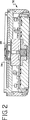
図3〜図5は、リニアベルトポリッシャ107の上方に位置決めされた1つの好ましいスピンドル組立体110を示しており、この場合、電磁式力発生装置は、スピンドル112の両側に位置決めされた1対のリニアモータ114を含む。リニアモータ114は、第1の空気静力学的軸受130によりスピンドル112に結合されている。空気静力学的軸受130は、スピンドル組立体110に提供される強制空気供給源132を用いてスピンドル112の周りにエアクッションを生じさせる。空気静力学的軸受130は、スピンドル112から半径方向に延びるフランジ138,140と協働して、エアクッションを用いてスピンドルの長手方向軸線に沿うスピンドルの望ましくない軸方向運動を防止するための空気静力学的スラスト軸受134,136を更に有している。第1の空気静力学的軸受130は好ましくは、スピンドル112の所定の長さにわたってスピンドルの周囲を完全に包囲している。第1の空気静力学的軸受は、スピンドル112をスピンドルの長手方向軸線の回りに実質的に摩擦の無い状態で回転させることができる。適当な空気静力学的軸受は、カリフォルニア州レッドウッド・シティ所在のシックス・デグリーズ・コンサルタンツ(Six Degrees Consultants )から入手できる。別の実施形態では、実質的に摩擦の無い状態の適当な回転レベルを達成するためには1つのスラスト軸受及び1つのフランジが必要であるに過ぎない。
【0020】
リニアモータ114は、スピンドル112の長手方向軸線に沿う位置及び力の制御を可能にする。各リニアモータは、電圧源148から電力を受け取る多数の巻線146を備えたステータ144を有している。各リニアモータ114は、スピンドル112の周りに同軸状に配置されたリニアガイド組立体151に取り付けられたロータ150を更に有している。各ロータ150に設けられたロータ磁石152は、固定フレーム(図示せず)に取り付けられた対応関係をなすステータ144のコイル146と協働するように設計されている。動作原理を説明すると、熱がリニアモータ114により生じる。水供給源166を用いて、水をコイル146に隣接した各ステータ144内の冷却チャネル中に圧送して過剰の熱を除くのがよい。
【0021】
第2の空気静力学的軸受142が、ロータ144とステータ150との間の空隙を維持し、リニアモータ内の摩擦を実質的に無くす。第2の空気静力学的軸受142は、第2の強制空気供給源156から加圧空気の流れを受け入れる。第2の空気静力学的軸受は、スピンドル組立体112中の摩擦及びこれに伴う摩擦ヒステリシス効果を減少させる。従来型リニアレール軸受を用いてもよいが、空気静力学的軸受を用いることが好ましい。と言うのは、これらは、リニアモータのロータとステータとの間に生じる大きな吸引力を取り扱うのに好適だからである。代表的なリニアレール軸受は、リニアモータで可能な力出力分解能を越える摩擦ヒステリシスを生じさせる。空気静力学的軸受で達成できる低摩擦結果に加え、空気静力学的軸受142を用いると、リニア軸受と比較して、スピンドル112の半径方向心振れ特性が向上する。
【0022】
一実施形態では、リニアモータ114は、所望範囲の圧力を加工物のところに生じさせることができる任意市販のリニアモータである。例えば、分解能が約2ミクロン、直線的力発生能力が1350ポンドフィートのリニアモータ、例えば、カリフォルニア州ラグナ・ヒルズ所在のコールモーゲン(Kollmorgen)カンパニイから入手できる部品番号IC33-200A2-640-640-AC-HDIC-100-P1-TRを用いることができる。空気供給源は、所望の空気圧を維持することができる多くの市販の空気ポンプのうち任意のものであってよい。空気静力学的軸受の各々によって生じる空隙は好ましくは、少なくとも0.001インチ(0.0254mm)である。水供給源は、リニアモータの動作温度を所望の範囲内に維持することができる任意の標準型水循環系統であるのがよい。
【0023】
スピンドル組立体110を、スピンドルの一方の側に取り付けられた単一のリニアモータと共に用いるのがよい。スピンドル112の両側に取り付けられる1対のリニアモータ114(図3及び図4)が好ましい。と言うのは、互いに反対側に位置したリニアモータば、第2の空気静力学的軸受142に関する種々の要件を最小限に抑えるからである。スピンドルの周囲にぐるりとバランスを取った状態で設けられた他のリニアモータ類も又使用できる。好ましくは、多くのリニアモータの使用では、各リニアモータについて別個のサーボコントローラ(各サーボコントローラはそれ自体の位置を維持する)及び各リニアモータについて必要な位置フィードバック及び力制御フィードバックを計算に入れるための力フィードバックループが挙げられる。
【0024】
図3〜図5に示すスピンドル組立110の利点は、サーボ制御の電磁式力発生装置、この例では、1対のリニアモータ114が、空気静力学的軸受と協働して本質的に摩擦が無く制御性の高い力/位置システムをもたらすことにある。リニアモータは2つの機能を発揮する。これらリニアモータは、一定の電磁力を直接スピンドルに加え、また、スピンドルを加工物の研磨/バフ磨きのためのプログラム可能な高さ位置まで下降させる。これらリニアモータはまた、少なくともP/2n の力出力分解能に対応し、ここで、Pは、電磁式力発生装置によって生じる最大力であり、nは、力発生装置を制御するために用いられるサーボコントローラ16(図1)の出力分解能である。力制御フィードバックループの精度を最大にするため、ウェーハキャリヤ30内に設けられたロードセルを、ロードセルの現寸にわたってマルチポイント校正法を用いて校正するのがよい。さらに、サーボコントローラを、直線補間法、曲線補間法、又は任意所望の順序の非線形(一次)関数を用いてロードセルから受け取った信号を変換し、非線形応答性を補償するようプログラムするのがよい。
【0025】
別の好ましい実施形態では、単一の円筒形音声コイル又は円筒形リニアモータを用いて半径方向の力のバランスを付加的にもたらし、取付け上の問題を単純化するのがよい。円筒形音声コイル又は円筒形リニアモータにおいても、ただ1対のフィードバックループが必要なだけである。
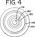
【0026】
再び図3を参照すると、DCサーボモータ158を用いてスピンドル112を回転させることができる。DCサーボモータ158は、スピンドルそれ自体に取り付けられた永久磁石160及びリニアモータのロータ150に取り付けられたコイル162を有している。電源164が、DCサーボモータ158のコイル162への給電を行う。DCサーボモータ158は、第1の空気静力学的軸受132を利用して実質的に摩擦の無い回転エネルギをスピンドルに与える。
【0027】
図1のスピンドル組立体を利用するスピンドル組立体10の動作原理が、図6に示されている。加工物、例えば半導体ウェーハを、スピンドルに着脱自在に取り付けられたウェーハホルダに取り付ける(符号200)。スピンドル組立体10のプロセッサが、動作パラメータをサーボコントローラに伝送する(符号202)。パラメータとしては、1組の位置ループ利得パラメータ及び1組の力制御利得パラメータが挙げられる。半導体ウェーハを加工面まで運ぶのに必要な初期粗動増分に関し、プロセッサは、力制御利得パラメータを0に設定し、0ではない位置ループ利得パラメータをサーボコントローラに与える。サーボコントローラは次に、スピンドルをスピンドルの長手方向軸線に沿って直線状に移動させて(符号204)、ついには、半導体ウェーハが加工面に接触するのに相当する所定の距離、スピンドルが移動するようにする(符号206)。
【0028】
この時点において、プロセッサは、位置フィードバックループ及び力制御フィードバックループに関して利得パラメータをリセットしてサーボコントローラがロードセルによって生じた荷重検出信号に応動するようにする(符号208)。プロセッサは、位置フィードバックループ利得を0に設定し、力制御フィードバック利得を0ではない値に設定することによってこれを達成する。力制御フィードバックループを利用して、今やスピンドルの位置をロードセルのところで測定された力に基づいて調節し、所望の圧力が検出されていないときにスピンドルが補償のために動くようにする(符号210,212)。平坦化、研磨又は他の加工をいったん完了すると、スピンドル組立体は、加えられた力のモニターを終了し、スピンドルを加工面から遠ざけて戻す(符号214)。さらに、DCサーボモータをスピンドルの端部に係合させてスピンドルをスピンドルの長手方向軸線回りに回転させることにより、半導体ウェーハ又は他の加工物を加工面に当接保持した状態で回転させることができる。
【0029】
スピンドル組立体10,110を用いることができる一つの好ましい環境は、半導体ウェーハを平坦化し又は研磨する化学機械的平坦化(CMP)システムである。ウェーハポリッシャと通称されている利用可能なCMPシステムでは、ウェーハを、平坦化されるべきウェーハ表面の平面内を移動する研磨パッドに接触させる回転ウェーハホルダが用いられることが多い。研磨流体、例えば、化学研磨剤又はミクロ研磨剤を含有したスラリーを研磨パッドに塗布してウェーハを研磨する。ウェーハホルダは次に、ウェーハを直線状に動き又は回転している研磨パッドに押し付け、これを回転させてウェーハを研磨すると共に平坦化する。スピンドル組立体に用いることができる1つの適当なリニアウェーハポリッシャは、カリフォルニア州フレモント所在のラム・リサーチ・コーポレイションから入手できるTERES(登録商標)ポリッシャである。
【0030】
上記のことから、力制御方式スピンドル組立体のための方法及び装置について説明した。本発明の方法の一実施形態は、位置フィードバックループでスピンドルの位置をモニターすることにより力発生装置でスピンドルを粗動増分状態で加工面に向かって移動させる工程を有する。加工物がスピンドルの一端に設けられた保持装置に取付け状態でいったん加工面に達すると、位置フィードバックループ及び力制御フィードバックループの利得パラメータを変え、スピンドル組立体は、力の測定値に基づいてスピンドルの位置を調節する。
【0031】
力制御方式研磨のためのスピンドル組立体も又、開示されている。一実施形態では、スピンドル組立体は、回転自在な軸方向に動くことができるスピンドル及びスピンドルに作動的に結合された力発生装置を有している。サーボコントローラが、力発生装置と連絡状態にあり、このサーボコントローラは、第1のフィードバックループ又は第2のフィードバックループからの情報に基づいて制御信号を力発生装置に与える。第1のフィードバックループは、スピンドル位置に関する情報を提供し、第2のフィードバックループはスピンドルの端部に取り付けられた加工物のところで検出される圧力に関する情報を提供する。同一の力発生装置は、スピンドルの位置を第1の作動モードで制御し、第2の作動モードにおいて加工物に加わる一定の力を維持するのに用いられる。力発生装置は好ましくは、電磁式力発生装置、例えば、1以上のリニアモータ又は音声コイルである。スピンドル組立体に関する力の分解能を最大にするため、好ましくは少なくとも1つの空気静力学的軸受を用いて、スピンドルの長手方向又は回転運動によって生じる摩擦を最小限に抑える。
【0032】
上述の詳細な説明は、本発明の限定ではなく説明として考えられるべきであり、以下の特許請求の範囲は、本発明の範囲(全ての均等例を含む)を定めるものである。
【図面の簡単な説明】
【図1】 本発明の好ましい実施形態の力制御方式研磨のためのスピンドル組立体の略図である。
【図2】 図1の装置に用いられるのに適したウェーハホルダの断面図である。
【図3】 図1の装置に用いられる力発生装置及びリニアベルトをポリッシャの断面図である。
【図4】 図3の4−4線矢視断面図である。
【図5】 図3の5−5線矢視断面図である。
【図6】 本発明の好ましい実施形態の図1のスピンドル組立体を制御する方法を示す流れ図である。[0001]
〔background〕
The present invention relates to a high performance spindle assembly for force controlled polishing of metals, plastics or other materials that require a certain force to be applied. In particular, the present invention relates to a spindle assembly for force controlled polishing or planarization of semiconductor wafers.
[0002]
Systems for applying force to a workpiece, such as a semiconductor wafer, have traditionally been interested in measuring the pressure applied at the spindle or monitoring the position of the spindle relative to the polishing surface. For example, one variation of a spindle assembly used for polishing workpieces is a vertically oriented spring balancing spindle that utilizes a single acting diaphragm cylinder as a downward force acting mechanism. In order to control the force output level of the diaphragm cylinder, a pneumatic proportional regulator is used with a built-in pressure transducer feedback loop connected to the diaphragm cylinder.
[0003]
In operation, this system lowers the spindle to the correct polishing height position using two different cylinder mechanisms. First, conventional piston cylinders lower the spindle to a mechanical hard stop. Next, pressurizing the diaphragm cylinder moves the spindle until the workpiece reaches the polished surface. A pressure transducer provided in the device monitors the performance of the diaphragm cylinder and feeds back the result to the pneumatic proportional regulator. Since the pressure transducer in this system is an integral component of the E / P regulator that supplies pressure to the diaphragm cylinder, the pneumatic proportional regulator does not receive the actual force applied to the workpiece by the spindle. . In practice, a certain amount of pressure applied by the diaphragm piston is lost due to frictional losses in the cylinders, bearings and various other mechanical components of the spindle assembly. This friction is not found in the pneumatic proportional regulator. This is because the differential pressure transducer only receives information from the diaphragm cylinder.
[0004]
Another system that provides a continuous downward force on the workpiece being polished includes a rotating diaphragm cylinder operatively connected to the spindle by a linkage. The spindle is guided by spline bearings that allow longitudinal and rotational movement by the spindle. The diaphragm cylinder is controlled by a servo valve as part of a proportional amplifier loop that receives feedback from between the servo valve and the diaphragm cylinder to monitor the position of the workpiece and the force applied thereto. . Again, the friction due to the diaphragm cylinder and the additional friction generated separately by the spline bearing guiding the spindle are not found in the servo valve control loop. Due to friction, a hysteresis effect may occur at the output. This hysteresis effect reduces the accuracy of position and force measurements. Therefore, there is a need for a spindle drive assembly that improves the accuracy of the downward force.
[0005]
[Summary of the Invention]
In order to improve the accuracy of conventional systems that provide a downward force on the workpiece in a polishing environment, the preferred embodiments described below improve the resolution of the spindle assembly force and provide a mechanical link in the spindle assembly. Reduce the friction caused by the device. Furthermore, these embodiments measure the force applied to the workpiece without using position or pressure feedback measured at a point on the spindle assembly located away from the workpiece, and force the servo control loop to Address the need to improve the polishing system by closing feedback.
[0006]
The spindle assembly described below for applying a constant pressure to the workpiece has a spindle that can move axially, and a holding device is connected to one end of the spindle. A load cell is attached to the holding device, and the load cell is positioned to detect a pressure applied to the workpiece and to output a load detection signal representing the applied pressure. A force generating device is operatively coupled to the spindle, the force generating device being configured to apply the force along the longitudinal axis of the spindle. A position detector is also operatively connected to the spindle, and the position detector is configured to output a position signal representative of the axial position of the spindle. A servo controller is in communication with the position detector via the first feedback loop, the load cell via the second feedback loop, and the force generator. The servo controller transmits a control signal to the force generator.
[0007]
A preferred method described below for workpiece force-controlled machining comprises the steps of moving an axially movable spindle along a longitudinal axis and monitoring the position of the spindle with a first feedback loop. . After the spindle has moved a predetermined amount, the method deactivates the first feedback loop, monitors the force applied to the workpiece via the second feedback loop, and is based on the force measured at the workpiece. Applying a constant force to the workpiece attached to one end of the spindle by continuously adjusting the position of the spindle. The same force generator is used to control the position of the spindle in the first operating mode and to control the force applied to the workpiece in the second operating mode. A preferred force generator is an electromagnetic force generator that cooperates with aerostatic bearings to reduce in-system friction during polishing / grinding operations and improve the resolution of force control with respect to the spindle.
[0008]
The summary section of this invention is merely an introductory part of this specification and is not intended to limit the scope of the invention as recited in the claims.
[0009]
Detailed Description of Preferred Embodiments
FIG. 1 shows a spindle assembly 10 of the present invention. The spindle assembly preferably includes a
[0010]
A position feedback loop is used when the spindle assembly operates in the alignment mode to monitor and control the overall axial movement of the spindle. For example, the spindle assembly 10 preferably uses a position feedback loop 18 that controls the axial spindle movement necessary to bring the workpiece from the standby position to the desired machining surface. The
[0011]
Once the workpiece is mounted on a holding device, such as a semiconductor wafer carrier 30 (see FIG. 2), and once transported to the processing surface in a state of being mounted on the
[0012]
As shown in FIG. 2, the
[0013]
An advantage obtained by sampling the force applied at the end of the
[0014]
Referring again to FIG. 1, the load detection signal transmitted from the
[0015]
A processor 28 (which may be a personal computer) controls the servo controller and continuously tracks the load detection signal sent to the force
[0016]
The servo controller's decision to switch between force feedback loop and position feedback may be based on any one of many criteria. In one embodiment, the servo controller is programmed to switch from position feedback to force feedback when the work piece contacts the work surface and the load cell outputs a signal representing the pressure applied to the work piece. In this embodiment, the servo controller is also programmed to automatically switch from a force feedback loop to a position feedback loop when the workpiece is pulled back from the work surface and the load cell no longer detects pressure. In another embodiment, the servo controller is programmed in a position mode that counts the number of steps that the spindle moves toward the work surface and switches from position feedback loop control to force feedback control at the end of the desired number of steps. It may be a thing. In yet another embodiment, the servo controller may be programmed to switch from position feedback to force feedback when the force generator moves the spindle at a desired speed and triggers an external device, such as an electric eye.
[0017]
According to one preferred embodiment, the
[0018]
As shown in FIG. 1, the preferred spindle assembly 10 includes a
[0019]
3-5 show one preferred spindle assembly 110 positioned above the linear belt polisher 107, in which the electromagnetic force generator is a pair of spindles positioned on either side of the
[0020]
The
[0021]
A second
[0022]
In one embodiment, the
[0023]
The spindle assembly 110 may be used with a single linear motor mounted on one side of the spindle. A pair of linear motors 114 (FIGS. 3 and 4) mounted on opposite sides of the
[0024]
The advantages of the spindle assembly 110 shown in FIGS. 3-5 are that a servo-controlled electromagnetic force generator, in this example, a pair of
[0025]
In another preferred embodiment, a single cylindrical voice coil or cylindrical linear motor may be used to additionally provide radial force balance, simplifying mounting problems. In a cylindrical voice coil or cylindrical linear motor, only a pair of feedback loops is required.
[0026]
Referring again to FIG. 3, the
[0027]
The principle of operation of the spindle assembly 10 utilizing the spindle assembly of FIG. 1 is illustrated in FIG. A workpiece such as a semiconductor wafer is attached to a wafer holder that is detachably attached to a spindle (reference numeral 200). The processor of the spindle assembly 10 transmits the operating parameters to the servo controller (reference numeral 202). The parameters include a set of position loop gain parameters and a set of force control gain parameters. With respect to the initial coarse increment required to carry the semiconductor wafer to the work surface, the processor sets the force control gain parameter to zero and provides a non-zero position loop gain parameter to the servo controller. Next, the servo controller moves the spindle linearly along the longitudinal axis of the spindle (reference numeral 204), and finally the spindle moves by a predetermined distance corresponding to the contact of the semiconductor wafer with the processing surface. (Reference numeral 206).
[0028]
At this point, the processor resets the gain parameters for the position feedback loop and the force control feedback loop so that the servo controller responds to the load detection signal generated by the load cell (reference numeral 208). The processor accomplishes this by setting the position feedback loop gain to zero and the force control feedback gain to a non-zero value. Utilizing a force control feedback loop, the position of the spindle is now adjusted based on the force measured at the load cell so that the spindle moves for compensation when the desired pressure is not detected (reference 210). 212). Once the planarization, polishing or other processing is complete, the spindle assembly terminates the applied force monitoring and returns the spindle away from the processing surface (reference numeral 214). Further, by rotating the spindle around the longitudinal axis of the spindle by engaging the DC servo motor with the end of the spindle, the semiconductor wafer or other workpiece can be rotated while being held in contact with the processing surface. it can.
[0029]
One preferred environment in which the spindle assemblies 10, 110 can be used is a chemical mechanical planarization (CMP) system that planarizes or polishes semiconductor wafers. Available CMP systems, commonly referred to as wafer polishers, often use rotating wafer holders that contact a wafer with a polishing pad that moves in the plane of the wafer surface to be planarized. A polishing fluid, such as a slurry containing a chemical or microabrasive, is applied to the polishing pad to polish the wafer. The wafer holder then presses the wafer against a linearly moving or rotating polishing pad and rotates it to polish and planarize the wafer. One suitable linear wafer polisher that can be used in the spindle assembly is the TERES® polisher available from Lam Research Corporation, Fremont, California.
[0030]
In view of the above, a method and apparatus for a force controlled spindle assembly has been described. One embodiment of the method of the present invention comprises the step of moving the spindle toward the work surface in a coarse increment with a force generator by monitoring the position of the spindle with a position feedback loop. Once the work piece reaches the work surface in a state of being attached to a holding device provided at one end of the spindle, the gain parameter of the position feedback loop and the force control feedback loop is changed, and the spindle assembly determines the spindle based on the force measurement. Adjust the position.
[0031]
A spindle assembly for force controlled polishing is also disclosed. In one embodiment, the spindle assembly includes a rotatable axially movable spindle and a force generator operatively coupled to the spindle. A servo controller is in communication with the force generator, and the servo controller provides a control signal to the force generator based on information from the first feedback loop or the second feedback loop. The first feedback loop provides information regarding the spindle position, and the second feedback loop provides information regarding the pressure detected at the workpiece attached to the end of the spindle. The same force generator is used to control the position of the spindle in the first mode of operation and maintain a constant force on the workpiece in the second mode of operation. The force generator is preferably an electromagnetic force generator, such as one or more linear motors or voice coils. In order to maximize the force resolution on the spindle assembly, preferably at least one aerostatic bearing is used to minimize friction caused by longitudinal or rotational movement of the spindle.
[0032]
The foregoing detailed description is to be considered as illustrative rather than limiting on the present invention, and the following claims define the scope of the present invention, including all equivalents.
[Brief description of the drawings]
FIG. 1 is a schematic diagram of a spindle assembly for force controlled polishing of a preferred embodiment of the present invention.
2 is a cross-sectional view of a wafer holder suitable for use in the apparatus of FIG.
3 is a cross-sectional view of a polisher of a force generator and a linear belt used in the apparatus of FIG. 1. FIG.
4 is a cross-sectional view taken along line 4-4 of FIG.
5 is a cross-sectional view taken along line 5-5 in FIG.
6 is a flow diagram illustrating a method of controlling the spindle assembly of FIG. 1 in a preferred embodiment of the present invention.
Claims (23)
前記加工物を保持する保持装置(30)と、
軸方向に可動のスピンドル(12)とを有し、前記保持装置(30)が前記軸方向に可動のスピンドル(12)の一方端に連結され、
前記保持装置(30)に取り付けられたロードセル(24)を有し、該ロードセル(24)が、前記加工物に加えられる圧力を検出し、加えられた圧力を示す荷重検出信号を出力するように位置決めされ、
前記軸方向に可動のスピンドル(12)に作動的に結合された力発生装置(14)を有し、該力発生装置(14)が、前記スピンドル(12)の長手方向軸線に沿って力を加えるように構成され、
前記スピンドル(12)に作動的に連結された位置検出器(20)を有し、該位置検出器(20)が、前記スピンドル(12)の軸方向位置を検出し、前記スピンドル(12)の軸方向位置を示す位置信号を出力するように位置決めされ、
前記位置信号を受け取ることができるように第1のフィードバックループ(18)を介して前記位置検出器(20)と連通し、前記荷重検出信号を受け取ることができるように第2のフィードバックループ(22)を介して前記ロードセル(24)と連通し、前記力発生装置(14)と連通しているサーボコントローラ(16)を有し、該サーボコントローラ(16)は、前記位置信号及び前記荷重検出信号に基づいて力発生装置(14)を制御する、
スピンドル組立体。A spindle assembly (10) for force control system machining of a workpiece,
A holding device (30) for holding the workpiece;
An axially movable spindle (12), and the holding device (30) is connected to one end of the axially movable spindle (12),
A load cell (24) attached to the holding device (30), wherein the load cell (24) detects a pressure applied to the workpiece and outputs a load detection signal indicating the applied pressure; Positioned,
A force generator (14) operatively coupled to the axially movable spindle (12), wherein the force generator (14) exerts a force along a longitudinal axis of the spindle (12); Configured to add
A position detector (20) operatively coupled to the spindle (12), the position detector (20) detecting an axial position of the spindle (12), and Positioned to output a position signal indicating the axial position,
A second feedback loop (22) communicates with the position detector (20) via a first feedback loop (18) to receive the position signal and receives the load detection signal. ) Through the load cell (24) and the servo controller (16) in communication with the force generator (14). The servo controller (16) includes the position signal and the load detection signal. controls the force generating device (14) based on the item,
Spindle assembly.
前記スピンドル(12)を長手方向軸線に沿って移動させ、
前記第1のフィードバックループ(18)を介して軸方向可動スピンドル(12)の位置をモニターし、
前記スピンドル(12)が第1位置に達したときに前記第1のフィードバックループ(18)を稼働解除し、
前記半導体ウェーハに加えられた圧力をモニターする第2のフィードバックループ(22)を稼働させ、
前記モニターした圧力に従って前記スピンドル(12)の位置を調節することによって前記スピンドル(12)の端の前記半導体ウェーハに加わる力を実質的に一定に維持することを含み、
前記スピンドル(12)の位置、及び、前記力発生装置(14)によって前記半導体ウェーハに加えられる圧力を、前記モニターした圧力及び前記モニターした位置によって、制御する、
方法。A method of processing a semiconductor wafer attached to one end of an axially movable spindle (12) operatively coupled to a force generator (14) by controlling the force, the force generator ( 14) is controlled by a first feedback loop (18) and a second feedback loop (22),
Moving the spindle (12) along the longitudinal axis;
Monitoring the position of the axially movable spindle (12) via the first feedback loop (18);
Deactivating the first feedback loop (18) when the spindle (12) reaches a first position;
Operating a second feedback loop (22) for monitoring the pressure applied to the semiconductor wafer;
Maintaining a substantially constant force applied to the semiconductor wafer at the end of the spindle (12) by adjusting the position of the spindle (12) according to the monitored pressure;
The position of the spindle (12) and the pressure applied to the semiconductor wafer by the force generator (14) are controlled by the monitored pressure and the monitored position .
Method.
回転自在で軸方向可動のスピンドル(12)と、
該回転自在で軸方向可動のスピンドル(12)の一方端に連結されたが保持装置(30)と、
前記スピンドル(12)に作動的に結合された電磁式力発生装置とを有し、該電磁式力発生装置が、前記スピンドル(12)の長手方向軸線に沿って力を加えるように構成され、
前記電磁式力発生装置と連通し、前記電磁式力発生装置に制御信号を出力するサーボコントローラ(16)と、
前記スピンドル(12)の位置を示す位置信号を位置検出器から前記サーボコントローラ(16)に伝送する第1のフィードバックループ(18)と、
前記スピンドル(12)によって前記加工物に加えられた圧力を示す荷重検出信号をロードセンサ(24)から前記サーボコントローラ(16)に伝送する第2のフィードバックループ(22)とを有し、前記ロードセンサ(24)が前記加工物に隣接して位置決めされ、
前記電磁式装置に提供された制御信号が、前記位置信号及び前記荷重検出信号に基づいて前記スピンドルの長手方向軸線に沿って力を制御するように作動する、
力制御方式スピンドル組立体。A force controlled spindle assembly (10) for applying a constant pressure to a workpiece,
A rotatable and axially movable spindle (12);
A holding device (30) connected to one end of the rotatable and axially movable spindle (12);
An electromagnetic force generator operatively coupled to the spindle (12), the electromagnetic force generator configured to apply a force along a longitudinal axis of the spindle (12);
A servo controller (16) communicating with the electromagnetic force generator and outputting a control signal to the electromagnetic force generator;
A first feedback loop (18) for transmitting a position signal indicating the position of the spindle (12) from a position detector to the servo controller (16);
A second feedback loop (22) for transmitting a load detection signal indicating a pressure applied to the workpiece by the spindle (12) from a load sensor (24) to the servo controller (16), A sensor (24) is positioned adjacent to the workpiece ;
A control signal provided to the electromagnetic device is operative to control a force along a longitudinal axis of the spindle based on the position signal and the load detection signal;
Force control spindle assembly.
前記加工物を保持する保持装置(30)と、
軸方向に可動のスピンドル(12)とを有し、前記保持装置(30)が前記軸方向に可動のスピンドル(12)の一方端に連結され、
前記保持装置(30)に取り付けられたロードセル(24)とを有し、該ロードセル(24)が、前記加工物に加えられる圧力を検出し、加えられた圧力を示す荷重検出信号を出力するように位置決めされ、
前記スピンドル(12)に作動的に連結された位置検出器(20)を有し、該位置検出器(20)が、前記スピンドル(12)の軸方向位置を検出し、前記スピンドル(12)の軸線方向位置を示す位置信号を発生させるよう位置決めされ、
前記軸方向可動スピンドル(12)に作動的に結合された力発生装置(14)を有し、該力発生装置(14)が、前記スピンドル(12)の長手方向軸線に沿って力を加えるように構成され、
前記力発生装置(14)、前記ロードセル(24)及び前記位置検出器(20)と連通しているサーボコントローラ(16)を有し、該サーボコントローラ(16)は、前記サーボコントローラ(16)が前記位置信号に基づいて前記力発生装置(14)を用いて前記スピンドル(12)の位置を制御する第1の作動モードと、前記サーボコントローラ(16)が前記荷重検出信号及び前記位置信号に基づいて、前記力発生装置(14)によって前記加工物に加えられる力を制御する第2の作動モードとを有する、
スピンドル組立体。A spindle assembly (10) for chemical mechanical planarization of a workpiece force control system comprising:
A holding device (30) for holding the workpiece;
An axially movable spindle (12), and the holding device (30) is connected to one end of the axially movable spindle (12),
A load cell (24) attached to the holding device (30), and the load cell (24) detects a pressure applied to the workpiece and outputs a load detection signal indicating the applied pressure. Is positioned on
A position detector (20) operatively coupled to the spindle (12), the position detector (20) detecting an axial position of the spindle (12), and Positioned to generate a position signal indicating the axial position,
A force generator (14) operatively coupled to the axially movable spindle (12), wherein the force generator (14) applies a force along the longitudinal axis of the spindle (12); Composed of
A servo controller (16) communicating with the force generator (14), the load cell (24), and the position detector (20), the servo controller (16) being configured by the servo controller (16); A first operation mode for controlling the position of the spindle (12) using the force generating device (14) based on the position signal, and the servo controller (16) based on the load detection signal and the position signal . A second mode of operation for controlling the force applied to the workpiece by the force generator (14),
Spindle assembly.
Applications Claiming Priority (3)
| Application Number | Priority Date | Filing Date | Title |
|---|---|---|---|
| US09/385,769 US6083082A (en) | 1999-08-30 | 1999-08-30 | Spindle assembly for force controlled polishing |
| US09/385,769 | 1999-08-30 | ||
| PCT/US2000/021843 WO2001015862A1 (en) | 1999-08-30 | 2000-08-11 | Spindle assembly for force controlled polishing |
Publications (3)
| Publication Number | Publication Date |
|---|---|
| JP2003508237A JP2003508237A (en) | 2003-03-04 |
| JP2003508237A5 JP2003508237A5 (en) | 2005-12-22 |
| JP4484413B2 true JP4484413B2 (en) | 2010-06-16 |
Family
ID=23522802
Family Applications (1)
| Application Number | Title | Priority Date | Filing Date |
|---|---|---|---|
| JP2001520259A Expired - Fee Related JP4484413B2 (en) | 1999-08-30 | 2000-08-11 | Spindle assembly for force controlled polishing |
Country Status (7)
| Country | Link |
|---|---|
| US (1) | US6083082A (en) |
| EP (1) | EP1207981B1 (en) |
| JP (1) | JP4484413B2 (en) |
| KR (1) | KR100717477B1 (en) |
| DE (1) | DE60007642T2 (en) |
| TW (1) | TW480207B (en) |
| WO (1) | WO2001015862A1 (en) |
Families Citing this family (23)
| Publication number | Priority date | Publication date | Assignee | Title |
|---|---|---|---|---|
| US6340326B1 (en) | 2000-01-28 | 2002-01-22 | Lam Research Corporation | System and method for controlled polishing and planarization of semiconductor wafers |
| US6705930B2 (en) * | 2000-01-28 | 2004-03-16 | Lam Research Corporation | System and method for polishing and planarizing semiconductor wafers using reduced surface area polishing pads and variable partial pad-wafer overlapping techniques |
| US6646364B1 (en) * | 2000-07-11 | 2003-11-11 | Honeywell International Inc. | MEMS actuator with lower power consumption and lower cost simplified fabrication |
| US6755723B1 (en) | 2000-09-29 | 2004-06-29 | Lam Research Corporation | Polishing head assembly |
| US6812598B2 (en) * | 2002-02-19 | 2004-11-02 | Rockwell Scientific Licensing, Llc | Multiple magnet transducer with differential magnetic strengths |
| US20030154923A1 (en) * | 2002-02-19 | 2003-08-21 | Innovative Technology Licensing, Llc | Mechanical translator with ultra low friction ferrofluid bearings |
| US6812583B2 (en) | 2002-02-19 | 2004-11-02 | Rockwell Scientific Licensing, Llc | Electrical generator with ferrofluid bearings |
| US6768230B2 (en) * | 2002-02-19 | 2004-07-27 | Rockwell Scientific Licensing, Llc | Multiple magnet transducer |
| US7288860B2 (en) * | 2002-02-19 | 2007-10-30 | Teledyne Licensing, Inc. | Magnetic transducer with ferrofluid end bearings |
| US6766679B1 (en) * | 2002-03-27 | 2004-07-27 | Lam Research Corporation | System and method for spindle drive downforce calibration |
| US6798090B2 (en) * | 2002-04-18 | 2004-09-28 | Rockwell Scientific Licensing, Llc | Electrical power generation by coupled magnets |
| US6935938B1 (en) | 2004-03-31 | 2005-08-30 | Lam Research Corporation | Multiple-conditioning member device for chemical mechanical planarization conditioning |
| US7040955B1 (en) * | 2005-01-28 | 2006-05-09 | Strasbaugh | Chemical-mechanical planarization tool force calibration method and system |
| JP2008246628A (en) * | 2007-03-30 | 2008-10-16 | Disco Abrasive Syst Ltd | Chuck table mechanism |
| JP4327880B2 (en) * | 2008-01-04 | 2009-09-09 | ファナック株式会社 | Servo motor controller with automatic gain adjustment function |
| JP5306065B2 (en) * | 2009-06-04 | 2013-10-02 | 株式会社荏原製作所 | Dressing apparatus and dressing method |
| US8408082B2 (en) * | 2009-11-18 | 2013-04-02 | General Electric Company | Apparatus to measure fluids in a conduit |
| JP5895154B2 (en) * | 2011-01-21 | 2016-03-30 | パナソニックIpマネジメント株式会社 | Driving method of linear actuator |
| US8550876B2 (en) | 2011-08-08 | 2013-10-08 | Apple Inc. | Force-controlled surface finishing through the use of a passive magnetic constant-force device |
| CN103586772B (en) * | 2012-08-16 | 2016-01-06 | 鸿富锦精密工业(深圳)有限公司 | Pressure-detecting device |
| US9898000B2 (en) * | 2013-01-30 | 2018-02-20 | Akribis Systems Pte Ltd | Planar positioning system and method of using the same |
| CN110315421B (en) * | 2019-08-20 | 2023-12-26 | 江苏集萃精凯高端装备技术有限公司 | Crystal material homogenizing and polishing device and application method |
| JP7431589B2 (en) | 2020-01-17 | 2024-02-15 | 株式会社ディスコ | processing equipment |
Family Cites Families (27)
| Publication number | Priority date | Publication date | Assignee | Title |
|---|---|---|---|---|
| US3631634A (en) * | 1970-01-26 | 1972-01-04 | John L Weber | Polishing machine |
| US3691694A (en) * | 1970-11-02 | 1972-09-19 | Ibm | Wafer polishing machine |
| US3903653A (en) * | 1973-04-11 | 1975-09-09 | Harold J Imhoff | Lapping machine |
| DE2451549A1 (en) * | 1974-10-30 | 1976-08-12 | Mueller Georg Kugellager | LOADING AND UNLOADING DEVICE FOR PLATE-SHAPED SEMI-CONDUCTOR MATERIALS |
| US4009539A (en) * | 1975-06-16 | 1977-03-01 | Spitfire Tool & Machine Co., Inc. | Lapping machine with vacuum workholder |
| US4020600A (en) * | 1976-08-13 | 1977-05-03 | Spitfire Tool & Machine Co., Inc. | Polishing fixture |
| US4141180A (en) * | 1977-09-21 | 1979-02-27 | Kayex Corporation | Polishing apparatus |
| US4450652A (en) * | 1981-09-04 | 1984-05-29 | Monsanto Company | Temperature control for wafer polishing |
| JPS59161262A (en) * | 1983-03-04 | 1984-09-12 | Masanori Kunieda | Magnetic attraction type method for abrasion |
| US4593495A (en) * | 1983-11-25 | 1986-06-10 | Toshiba Machine Co., Ltd. | Polishing machine |
| DE3479936D1 (en) * | 1983-12-12 | 1989-11-02 | Unisys Corp | Air bearing for moving webs |
| GB8402194D0 (en) * | 1984-01-27 | 1984-02-29 | Secr Defence | Chemical polishing apparatus |
| US4680893A (en) * | 1985-09-23 | 1987-07-21 | Motorola, Inc. | Apparatus for polishing semiconductor wafers |
| DK155299B (en) * | 1986-04-18 | 1989-03-20 | Struers As | APPLIANCE FOR GRINDING OR POLISHING TOPICS |
| CH684321A5 (en) * | 1988-04-07 | 1994-08-31 | Arthur Werner Staehli | Device on a double disk. |
| JPH01310859A (en) * | 1988-06-09 | 1989-12-14 | Toyoda Mach Works Ltd | Polishing machining device |
| US4934102A (en) * | 1988-10-04 | 1990-06-19 | International Business Machines Corporation | System for mechanical planarization |
| JP2827540B2 (en) * | 1991-03-11 | 1998-11-25 | 松下電器産業株式会社 | Polishing spindle |
| FR2677292B1 (en) * | 1991-06-04 | 1995-12-08 | Seva | POLISHING MACHINE WITH PNEUMATIC REGULATION OF THE EFFORT OF THE TOOL OF THE POLISHING PIECE. |
| FR2677291B1 (en) * | 1991-06-06 | 1995-12-15 | Commissariat Energie Atomique | PRESSURE CONTROL POLISHING MACHINE. |
| US5148632A (en) * | 1991-06-14 | 1992-09-22 | Corning Incorporated | Cavity forming in plastic body |
| JP3227199B2 (en) * | 1992-05-18 | 2001-11-12 | 株式会社リコー | Waste toner treatment method |
| US5658183A (en) * | 1993-08-25 | 1997-08-19 | Micron Technology, Inc. | System for real-time control of semiconductor wafer polishing including optical monitoring |
| US5456627A (en) * | 1993-12-20 | 1995-10-10 | Westech Systems, Inc. | Conditioner for a polishing pad and method therefor |
| US5643044A (en) * | 1994-11-01 | 1997-07-01 | Lund; Douglas E. | Automatic chemical and mechanical polishing system for semiconductor wafers |
| US5618447A (en) * | 1996-02-13 | 1997-04-08 | Micron Technology, Inc. | Polishing pad counter meter and method for real-time control of the polishing rate in chemical-mechanical polishing of semiconductor wafers |
| JPH1071560A (en) * | 1996-08-27 | 1998-03-17 | Speedfam Co Ltd | Wafer pressurizing device |
-
1999
- 1999-08-30 US US09/385,769 patent/US6083082A/en not_active Expired - Lifetime
-
2000
- 2000-08-11 DE DE60007642T patent/DE60007642T2/en not_active Expired - Fee Related
- 2000-08-11 WO PCT/US2000/021843 patent/WO2001015862A1/en active IP Right Grant
- 2000-08-11 EP EP00955424A patent/EP1207981B1/en not_active Expired - Lifetime
- 2000-08-11 JP JP2001520259A patent/JP4484413B2/en not_active Expired - Fee Related
- 2000-08-11 KR KR1020027002464A patent/KR100717477B1/en not_active IP Right Cessation
- 2000-08-29 TW TW089117518A patent/TW480207B/en not_active IP Right Cessation
Also Published As
| Publication number | Publication date |
|---|---|
| EP1207981A1 (en) | 2002-05-29 |
| US6083082A (en) | 2000-07-04 |
| DE60007642D1 (en) | 2004-02-12 |
| KR100717477B1 (en) | 2007-05-14 |
| TW480207B (en) | 2002-03-21 |
| DE60007642T2 (en) | 2004-10-07 |
| EP1207981B1 (en) | 2004-01-07 |
| KR20020027583A (en) | 2002-04-13 |
| JP2003508237A (en) | 2003-03-04 |
| WO2001015862A1 (en) | 2001-03-08 |
Similar Documents
| Publication | Publication Date | Title |
|---|---|---|
| JP4484413B2 (en) | Spindle assembly for force controlled polishing | |
| US6508614B1 (en) | Spindle device and machine tool utilizing the same | |
| US9427844B2 (en) | Centering machine for workpieces, particularly optical lenses | |
| US5951368A (en) | Polishing apparatus | |
| KR100987564B1 (en) | Indexing Apparatus | |
| JPH01501298A (en) | Workpiece carrying spindle assemblies with magnetic bearings and devices for providing such assemblies for extremely high precision machine tools | |
| JP2003508237A5 (en) | ||
| JPH01501297A (en) | Ultra-precision machining method and apparatus for finishing irregular rotating surfaces and performing servo-controlled machining | |
| JPH08252753A (en) | Grinding equipment | |
| KR100356440B1 (en) | Grinder | |
| JP3789650B2 (en) | Processing machine and spindle device thereof | |
| US5718617A (en) | Grinding force measurement system for computer controlled grinding operations | |
| KR20220027756A (en) | Spindle unit and machining apparatus | |
| JP2000263377A (en) | Metal mold machining device | |
| JPH07295649A (en) | Stage controller | |
| CN208818424U (en) | A kind of electromagnetic type on-line dynamic balancing system | |
| JP2022065818A (en) | Grinding device | |
| CN212947071U (en) | Mechanism suitable for adjusting working pressure of contact wheel of belt sander | |
| JP2000042867A (en) | Rotary positioning device | |
| JPH10545A (en) | Polishing head | |
| JPS61260973A (en) | Hand for robot | |
| JP2002361546A (en) | Grinding device | |
| JP2001322045A (en) | Stage control device | |
| JPH09239628A (en) | Self-weight bearing device | |
| JPH01310859A (en) | Polishing machining device |
Legal Events
| Date | Code | Title | Description |
|---|---|---|---|
| A521 | Written amendment |
Free format text: JAPANESE INTERMEDIATE CODE: A523 Effective date: 20041021 |
|
| A621 | Written request for application examination |
Free format text: JAPANESE INTERMEDIATE CODE: A621 Effective date: 20041021 |
|
| A131 | Notification of reasons for refusal |
Free format text: JAPANESE INTERMEDIATE CODE: A131 Effective date: 20070604 |
|
| A601 | Written request for extension of time |
Free format text: JAPANESE INTERMEDIATE CODE: A601 Effective date: 20070904 |
|
| A602 | Written permission of extension of time |
Free format text: JAPANESE INTERMEDIATE CODE: A602 Effective date: 20070911 |
|
| A521 | Written amendment |
Free format text: JAPANESE INTERMEDIATE CODE: A523 Effective date: 20071203 |
|
| A131 | Notification of reasons for refusal |
Free format text: JAPANESE INTERMEDIATE CODE: A131 Effective date: 20081104 |
|
| A601 | Written request for extension of time |
Free format text: JAPANESE INTERMEDIATE CODE: A601 Effective date: 20090204 |
|
| A602 | Written permission of extension of time |
Free format text: JAPANESE INTERMEDIATE CODE: A602 Effective date: 20090212 |
|
| A601 | Written request for extension of time |
Free format text: JAPANESE INTERMEDIATE CODE: A601 Effective date: 20090304 |
|
| A602 | Written permission of extension of time |
Free format text: JAPANESE INTERMEDIATE CODE: A602 Effective date: 20090311 |
|
| A601 | Written request for extension of time |
Free format text: JAPANESE INTERMEDIATE CODE: A601 Effective date: 20090406 |
|
| A602 | Written permission of extension of time |
Free format text: JAPANESE INTERMEDIATE CODE: A602 Effective date: 20090413 |
|
| A711 | Notification of change in applicant |
Free format text: JAPANESE INTERMEDIATE CODE: A711 Effective date: 20090907 |
|
| A521 | Written amendment |
Free format text: JAPANESE INTERMEDIATE CODE: A821 Effective date: 20090907 |
|
| TRDD | Decision of grant or rejection written | ||
| A01 | Written decision to grant a patent or to grant a registration (utility model) |
Free format text: JAPANESE INTERMEDIATE CODE: A01 Effective date: 20100302 |
|
| A01 | Written decision to grant a patent or to grant a registration (utility model) |
Free format text: JAPANESE INTERMEDIATE CODE: A01 |
|
| A61 | First payment of annual fees (during grant procedure) |
Free format text: JAPANESE INTERMEDIATE CODE: A61 Effective date: 20100323 |
|
| R150 | Certificate of patent or registration of utility model |
Free format text: JAPANESE INTERMEDIATE CODE: R150 |
|
| FPAY | Renewal fee payment (event date is renewal date of database) |
Free format text: PAYMENT UNTIL: 20130402 Year of fee payment: 3 |
|
| FPAY | Renewal fee payment (event date is renewal date of database) |
Free format text: PAYMENT UNTIL: 20130402 Year of fee payment: 3 |
|
| RD02 | Notification of acceptance of power of attorney |
Free format text: JAPANESE INTERMEDIATE CODE: R3D02 |
|
| FPAY | Renewal fee payment (event date is renewal date of database) |
Free format text: PAYMENT UNTIL: 20140402 Year of fee payment: 4 |
|
| R250 | Receipt of annual fees |
Free format text: JAPANESE INTERMEDIATE CODE: R250 |
|
| R250 | Receipt of annual fees |
Free format text: JAPANESE INTERMEDIATE CODE: R250 |
|
| R250 | Receipt of annual fees |
Free format text: JAPANESE INTERMEDIATE CODE: R250 |
|
| R250 | Receipt of annual fees |
Free format text: JAPANESE INTERMEDIATE CODE: R250 |
|
| LAPS | Cancellation because of no payment of annual fees |