JP4478457B2 - Non-patterned nonwoven fabric and method for making the same - Google Patents
Non-patterned nonwoven fabric and method for making the same Download PDFInfo
- Publication number
- JP4478457B2 JP4478457B2 JP2003557477A JP2003557477A JP4478457B2 JP 4478457 B2 JP4478457 B2 JP 4478457B2 JP 2003557477 A JP2003557477 A JP 2003557477A JP 2003557477 A JP2003557477 A JP 2003557477A JP 4478457 B2 JP4478457 B2 JP 4478457B2
- Authority
- JP
- Japan
- Prior art keywords
- pattern
- region
- web
- areas
- tensile strength
- Prior art date
- Legal status (The legal status is an assumption and is not a legal conclusion. Google has not performed a legal analysis and makes no representation as to the accuracy of the status listed.)
- Expired - Lifetime
Links
Images


Classifications
-
- A—HUMAN NECESSITIES
- A61—MEDICAL OR VETERINARY SCIENCE; HYGIENE
- A61F—FILTERS IMPLANTABLE INTO BLOOD VESSELS; PROSTHESES; DEVICES PROVIDING PATENCY TO, OR PREVENTING COLLAPSING OF, TUBULAR STRUCTURES OF THE BODY, e.g. STENTS; ORTHOPAEDIC, NURSING OR CONTRACEPTIVE DEVICES; FOMENTATION; TREATMENT OR PROTECTION OF EYES OR EARS; BANDAGES, DRESSINGS OR ABSORBENT PADS; FIRST-AID KITS
- A61F13/00—Bandages or dressings; Absorbent pads
- A61F13/15—Absorbent pads, e.g. sanitary towels, swabs or tampons for external or internal application to the body; Supporting or fastening means therefor; Tampon applicators
- A61F13/53—Absorbent pads, e.g. sanitary towels, swabs or tampons for external or internal application to the body; Supporting or fastening means therefor; Tampon applicators characterised by the absorbing medium
- A61F13/539—Absorbent pads, e.g. sanitary towels, swabs or tampons for external or internal application to the body; Supporting or fastening means therefor; Tampon applicators characterised by the absorbing medium characterised by the connection of the absorbent layers with each other or with the outer layers
-
- A—HUMAN NECESSITIES
- A44—HABERDASHERY; JEWELLERY
- A44B—BUTTONS, PINS, BUCKLES, SLIDE FASTENERS, OR THE LIKE
- A44B18/00—Fasteners of the touch-and-close type; Making such fasteners
- A44B18/0003—Fastener constructions
- A44B18/0011—Female or loop elements
-
- A—HUMAN NECESSITIES
- A61—MEDICAL OR VETERINARY SCIENCE; HYGIENE
- A61F—FILTERS IMPLANTABLE INTO BLOOD VESSELS; PROSTHESES; DEVICES PROVIDING PATENCY TO, OR PREVENTING COLLAPSING OF, TUBULAR STRUCTURES OF THE BODY, e.g. STENTS; ORTHOPAEDIC, NURSING OR CONTRACEPTIVE DEVICES; FOMENTATION; TREATMENT OR PROTECTION OF EYES OR EARS; BANDAGES, DRESSINGS OR ABSORBENT PADS; FIRST-AID KITS
- A61F13/00—Bandages or dressings; Absorbent pads
- A61F13/15—Absorbent pads, e.g. sanitary towels, swabs or tampons for external or internal application to the body; Supporting or fastening means therefor; Tampon applicators
- A61F13/56—Supporting or fastening means
- A61F13/62—Mechanical fastening means, ; Fabric strip fastener elements, e.g. hook and loop
-
- D—TEXTILES; PAPER
- D04—BRAIDING; LACE-MAKING; KNITTING; TRIMMINGS; NON-WOVEN FABRICS
- D04H—MAKING TEXTILE FABRICS, e.g. FROM FIBRES OR FILAMENTARY MATERIAL; FABRICS MADE BY SUCH PROCESSES OR APPARATUS, e.g. FELTS, NON-WOVEN FABRICS; COTTON-WOOL; WADDING ; NON-WOVEN FABRICS FROM STAPLE FIBRES, FILAMENTS OR YARNS, BONDED WITH AT LEAST ONE WEB-LIKE MATERIAL DURING THEIR CONSOLIDATION
- D04H1/00—Non-woven fabrics formed wholly or mainly of staple fibres or like relatively short fibres
- D04H1/40—Non-woven fabrics formed wholly or mainly of staple fibres or like relatively short fibres from fleeces or layers composed of fibres without existing or potential cohesive properties
- D04H1/54—Non-woven fabrics formed wholly or mainly of staple fibres or like relatively short fibres from fleeces or layers composed of fibres without existing or potential cohesive properties by welding together the fibres, e.g. by partially melting or dissolving
-
- D—TEXTILES; PAPER
- D04—BRAIDING; LACE-MAKING; KNITTING; TRIMMINGS; NON-WOVEN FABRICS
- D04H—MAKING TEXTILE FABRICS, e.g. FROM FIBRES OR FILAMENTARY MATERIAL; FABRICS MADE BY SUCH PROCESSES OR APPARATUS, e.g. FELTS, NON-WOVEN FABRICS; COTTON-WOOL; WADDING ; NON-WOVEN FABRICS FROM STAPLE FIBRES, FILAMENTS OR YARNS, BONDED WITH AT LEAST ONE WEB-LIKE MATERIAL DURING THEIR CONSOLIDATION
- D04H1/00—Non-woven fabrics formed wholly or mainly of staple fibres or like relatively short fibres
- D04H1/40—Non-woven fabrics formed wholly or mainly of staple fibres or like relatively short fibres from fleeces or layers composed of fibres without existing or potential cohesive properties
- D04H1/58—Non-woven fabrics formed wholly or mainly of staple fibres or like relatively short fibres from fleeces or layers composed of fibres without existing or potential cohesive properties by applying, incorporating or activating chemical or thermoplastic bonding agents, e.g. adhesives
- D04H1/64—Non-woven fabrics formed wholly or mainly of staple fibres or like relatively short fibres from fleeces or layers composed of fibres without existing or potential cohesive properties by applying, incorporating or activating chemical or thermoplastic bonding agents, e.g. adhesives the bonding agent being applied in wet state, e.g. chemical agents in dispersions or solutions
- D04H1/66—Non-woven fabrics formed wholly or mainly of staple fibres or like relatively short fibres from fleeces or layers composed of fibres without existing or potential cohesive properties by applying, incorporating or activating chemical or thermoplastic bonding agents, e.g. adhesives the bonding agent being applied in wet state, e.g. chemical agents in dispersions or solutions at spaced points or locations
-
- D—TEXTILES; PAPER
- D04—BRAIDING; LACE-MAKING; KNITTING; TRIMMINGS; NON-WOVEN FABRICS
- D04H—MAKING TEXTILE FABRICS, e.g. FROM FIBRES OR FILAMENTARY MATERIAL; FABRICS MADE BY SUCH PROCESSES OR APPARATUS, e.g. FELTS, NON-WOVEN FABRICS; COTTON-WOOL; WADDING ; NON-WOVEN FABRICS FROM STAPLE FIBRES, FILAMENTS OR YARNS, BONDED WITH AT LEAST ONE WEB-LIKE MATERIAL DURING THEIR CONSOLIDATION
- D04H3/00—Non-woven fabrics formed wholly or mainly of yarns or like filamentary material of substantial length
- D04H3/08—Non-woven fabrics formed wholly or mainly of yarns or like filamentary material of substantial length characterised by the method of strengthening or consolidating
- D04H3/14—Non-woven fabrics formed wholly or mainly of yarns or like filamentary material of substantial length characterised by the method of strengthening or consolidating with bonds between thermoplastic yarns or filaments produced by welding
-
- A—HUMAN NECESSITIES
- A61—MEDICAL OR VETERINARY SCIENCE; HYGIENE
- A61F—FILTERS IMPLANTABLE INTO BLOOD VESSELS; PROSTHESES; DEVICES PROVIDING PATENCY TO, OR PREVENTING COLLAPSING OF, TUBULAR STRUCTURES OF THE BODY, e.g. STENTS; ORTHOPAEDIC, NURSING OR CONTRACEPTIVE DEVICES; FOMENTATION; TREATMENT OR PROTECTION OF EYES OR EARS; BANDAGES, DRESSINGS OR ABSORBENT PADS; FIRST-AID KITS
- A61F13/00—Bandages or dressings; Absorbent pads
- A61F13/15—Absorbent pads, e.g. sanitary towels, swabs or tampons for external or internal application to the body; Supporting or fastening means therefor; Tampon applicators
- A61F13/84—Accessories, not otherwise provided for, for absorbent pads
- A61F2013/8497—Accessories, not otherwise provided for, for absorbent pads having decorations or indicia means
-
- Y—GENERAL TAGGING OF NEW TECHNOLOGICAL DEVELOPMENTS; GENERAL TAGGING OF CROSS-SECTIONAL TECHNOLOGIES SPANNING OVER SEVERAL SECTIONS OF THE IPC; TECHNICAL SUBJECTS COVERED BY FORMER USPC CROSS-REFERENCE ART COLLECTIONS [XRACs] AND DIGESTS
- Y10—TECHNICAL SUBJECTS COVERED BY FORMER USPC
- Y10T—TECHNICAL SUBJECTS COVERED BY FORMER US CLASSIFICATION
- Y10T428/00—Stock material or miscellaneous articles
- Y10T428/24—Structurally defined web or sheet [e.g., overall dimension, etc.]
- Y10T428/24008—Structurally defined web or sheet [e.g., overall dimension, etc.] including fastener for attaching to external surface
- Y10T428/24017—Hook or barb
-
- Y—GENERAL TAGGING OF NEW TECHNOLOGICAL DEVELOPMENTS; GENERAL TAGGING OF CROSS-SECTIONAL TECHNOLOGIES SPANNING OVER SEVERAL SECTIONS OF THE IPC; TECHNICAL SUBJECTS COVERED BY FORMER USPC CROSS-REFERENCE ART COLLECTIONS [XRACs] AND DIGESTS
- Y10—TECHNICAL SUBJECTS COVERED BY FORMER USPC
- Y10T—TECHNICAL SUBJECTS COVERED BY FORMER US CLASSIFICATION
- Y10T428/00—Stock material or miscellaneous articles
- Y10T428/24—Structurally defined web or sheet [e.g., overall dimension, etc.]
- Y10T428/24025—Superposed movable attached layers or components
-
- Y—GENERAL TAGGING OF NEW TECHNOLOGICAL DEVELOPMENTS; GENERAL TAGGING OF CROSS-SECTIONAL TECHNOLOGIES SPANNING OVER SEVERAL SECTIONS OF THE IPC; TECHNICAL SUBJECTS COVERED BY FORMER USPC CROSS-REFERENCE ART COLLECTIONS [XRACs] AND DIGESTS
- Y10—TECHNICAL SUBJECTS COVERED BY FORMER USPC
- Y10T—TECHNICAL SUBJECTS COVERED BY FORMER US CLASSIFICATION
- Y10T428/00—Stock material or miscellaneous articles
- Y10T428/24—Structurally defined web or sheet [e.g., overall dimension, etc.]
- Y10T428/24033—Structurally defined web or sheet [e.g., overall dimension, etc.] including stitching and discrete fastener[s], coating or bond
- Y10T428/24041—Discontinuous or differential coating, impregnation, or bond
-
- Y—GENERAL TAGGING OF NEW TECHNOLOGICAL DEVELOPMENTS; GENERAL TAGGING OF CROSS-SECTIONAL TECHNOLOGIES SPANNING OVER SEVERAL SECTIONS OF THE IPC; TECHNICAL SUBJECTS COVERED BY FORMER USPC CROSS-REFERENCE ART COLLECTIONS [XRACs] AND DIGESTS
- Y10—TECHNICAL SUBJECTS COVERED BY FORMER USPC
- Y10T—TECHNICAL SUBJECTS COVERED BY FORMER US CLASSIFICATION
- Y10T428/00—Stock material or miscellaneous articles
- Y10T428/24—Structurally defined web or sheet [e.g., overall dimension, etc.]
- Y10T428/24058—Structurally defined web or sheet [e.g., overall dimension, etc.] including grain, strips, or filamentary elements in respective layers or components in angular relation
- Y10T428/24074—Strand or strand-portions
- Y10T428/24091—Strand or strand-portions with additional layer[s]
- Y10T428/24099—On each side of strands or strand-portions
-
- Y—GENERAL TAGGING OF NEW TECHNOLOGICAL DEVELOPMENTS; GENERAL TAGGING OF CROSS-SECTIONAL TECHNOLOGIES SPANNING OVER SEVERAL SECTIONS OF THE IPC; TECHNICAL SUBJECTS COVERED BY FORMER USPC CROSS-REFERENCE ART COLLECTIONS [XRACs] AND DIGESTS
- Y10—TECHNICAL SUBJECTS COVERED BY FORMER USPC
- Y10T—TECHNICAL SUBJECTS COVERED BY FORMER US CLASSIFICATION
- Y10T428/00—Stock material or miscellaneous articles
- Y10T428/29—Coated or structually defined flake, particle, cell, strand, strand portion, rod, filament, macroscopic fiber or mass thereof
- Y10T428/2904—Staple length fiber
-
- Y—GENERAL TAGGING OF NEW TECHNOLOGICAL DEVELOPMENTS; GENERAL TAGGING OF CROSS-SECTIONAL TECHNOLOGIES SPANNING OVER SEVERAL SECTIONS OF THE IPC; TECHNICAL SUBJECTS COVERED BY FORMER USPC CROSS-REFERENCE ART COLLECTIONS [XRACs] AND DIGESTS
- Y10—TECHNICAL SUBJECTS COVERED BY FORMER USPC
- Y10T—TECHNICAL SUBJECTS COVERED BY FORMER US CLASSIFICATION
- Y10T442/00—Fabric [woven, knitted, or nonwoven textile or cloth, etc.]
- Y10T442/60—Nonwoven fabric [i.e., nonwoven strand or fiber material]
- Y10T442/637—Including strand or fiber material which is a monofilament composed of two or more polymeric materials in physically distinct relationship [e.g., sheath-core, side-by-side, islands-in-sea, fibrils-in-matrix, etc.] or composed of physical blend of chemically different polymeric materials or a physical blend of a polymeric material and a filler material
-
- Y—GENERAL TAGGING OF NEW TECHNOLOGICAL DEVELOPMENTS; GENERAL TAGGING OF CROSS-SECTIONAL TECHNOLOGIES SPANNING OVER SEVERAL SECTIONS OF THE IPC; TECHNICAL SUBJECTS COVERED BY FORMER USPC CROSS-REFERENCE ART COLLECTIONS [XRACs] AND DIGESTS
- Y10—TECHNICAL SUBJECTS COVERED BY FORMER USPC
- Y10T—TECHNICAL SUBJECTS COVERED BY FORMER US CLASSIFICATION
- Y10T442/00—Fabric [woven, knitted, or nonwoven textile or cloth, etc.]
- Y10T442/60—Nonwoven fabric [i.e., nonwoven strand or fiber material]
- Y10T442/659—Including an additional nonwoven fabric
-
- Y—GENERAL TAGGING OF NEW TECHNOLOGICAL DEVELOPMENTS; GENERAL TAGGING OF CROSS-SECTIONAL TECHNOLOGIES SPANNING OVER SEVERAL SECTIONS OF THE IPC; TECHNICAL SUBJECTS COVERED BY FORMER USPC CROSS-REFERENCE ART COLLECTIONS [XRACs] AND DIGESTS
- Y10—TECHNICAL SUBJECTS COVERED BY FORMER USPC
- Y10T—TECHNICAL SUBJECTS COVERED BY FORMER US CLASSIFICATION
- Y10T442/00—Fabric [woven, knitted, or nonwoven textile or cloth, etc.]
- Y10T442/60—Nonwoven fabric [i.e., nonwoven strand or fiber material]
- Y10T442/674—Nonwoven fabric with a preformed polymeric film or sheet
Description
(技術分野)
本発明は、一般に、不織布及び不織ウェブの分野、及びこれを製造する方法に関する。より具体的には、本発明は、パターン非結合域を有する不織布及びウェブに関する。
(Technical field)
The present invention relates generally to the field of non-woven and non-woven webs and methods for making the same. More specifically, the present invention relates to non-woven fabrics and webs having pattern unbonded areas.
(背景技術)
フック・ループファスナシステムとも呼ばれる種類の機械的締結システムは、種々の消費者用及び産業用用途においてますます広く用いられるようになった。このような用途の幾つかの例は、使い捨てパーソナルケア吸収性物品、衣服、スポーツ用品の備品その他の広域に渡る雑多な部品を含む。典型的には、このようなフック・ループ式締結システムは、2つ又はそれ以上の材料又は物品の間に再締結可能な連結が望まれる状況において用いられる。これらの機械的締結システムは、多くの場合において、ボタン、バックル、ジッパーその他同様なもののような再締結可能な連結を作るのに用いられる他の通常の装置に取って代わった。
(Background technology)
A type of mechanical fastening system, also referred to as a hook and loop fastener system, has become increasingly popular in a variety of consumer and industrial applications. Some examples of such applications include disposable personal care absorbent articles, clothing, sports equipment fixtures and other miscellaneous parts over a wide area. Typically, such hook and loop fastening systems are used in situations where a refastenable connection is desired between two or more materials or articles. These mechanical fastening systems have in many cases replaced other conventional devices used to make refastenable connections such as buttons, buckles, zippers and the like.
機械的締結システムは、典型的には、2つの部品、すなわち雄(フック)部品及び雌(ループ)部品を用いる。フック部品は、通常は、ベース材料に固定されるか又は連結された複数の半剛性のフック形状要素を含む。ループ部品は、一般には、弾性のある裏材材料を含み、ここから複数の直立したループが突出している。フック部品のフック形状要素は、ループ材料のループを係合するように設計され、これにより機械的結合が、2つの部品のフック要素及びループ要素の間に形成されるようになる。これらの機械的結合は、通常使用中にそれぞれの部品が分離することを避けるように機能する。このような機械的締結システムは、フック・ループ部品の連結表面に対して平行であるか又はこれにより定められた平面に適用される剪断力又は応力、並びに、特定の剥離力又は応力の適用による該フック・ループ部品の分離を避けるように設計される。しかしながら、フック・ループ部品の連結表面により定められる平面に対してほぼ垂直であるか又は直角方向の剥離力を適用することは、例えば、ループ要素が壊れてこれにより係合されたフック要素が解除されるようになることにより、又は該フック要素が該ループ要素から外れるまで弾性フック要素を曲げることにより、該フック要素の該ループ要素からの分離を生じさせることになる。 Mechanical fastening systems typically use two parts: a male (hook) part and a female (loop) part. The hook component typically includes a plurality of semi-rigid hook-shaped elements that are fixed or coupled to the base material. The loop component typically includes an elastic backing material from which a plurality of upstanding loops protrude. The hook-shaped element of the hook part is designed to engage a loop of loop material so that a mechanical bond is formed between the hook element and the loop element of the two parts. These mechanical connections function to avoid separation of each part during normal use. Such a mechanical fastening system is based on the application of a specific peeling force or stress, as well as a shearing force or stress applied to a plane parallel to or defined by the connecting surfaces of the hook and loop parts. Designed to avoid separation of the hook and loop parts. However, applying a peel force that is substantially perpendicular or perpendicular to the plane defined by the connecting surface of the hook-and-loop component, for example, breaks the loop element and thereby releases the engaged hook element. Being done or bending the elastic hook element until the hook element disengages from the loop element will cause separation of the hook element from the loop element.
機械的締結システムは、使い捨ておむつ、使い捨て衣料、使い捨て失禁用製品その他同様なもののような使い捨てパーソナルケア吸収部品に用いることができるという利点を有する。このような使い捨て製品は、一般には、単用品であり、普通は数時間である比較的短期間の使用後には捨てられ、洗濯して再使用されることは意図されていない。その結果、このような製品の設計においては高価な部品を避けるようにすることが望ましい。したがって、フック・ループ部品がこのような製品に用いられるという点で、該フック・ループ部品は用いられる材料及びこれらの部品を作るための製造プ方法の両方について、比較的安価である必要がある。他方では、フック・ループ部品は、フック・ループ部品の時期尚早の分離又は外れによりもたらされることがある着用者にとって可能性のあるばつの悪い状況を避けるようにするために、吸収性物品の通常の着用中に、そこに適用される力に耐えるのに十分な構造的一体性及び弾性を持たなければならない。 Mechanical fastening systems have the advantage that they can be used in disposable personal care absorbent parts such as disposable diapers, disposable garments, disposable incontinence products and the like. Such disposable products are generally single items that are discarded after a relatively short period of use, usually several hours, and are not intended to be washed and reused. As a result, it is desirable to avoid expensive parts in the design of such products. Therefore, in that hook and loop parts are used in such products, the hook and loop parts need to be relatively inexpensive, both for the materials used and the manufacturing process for making these parts. . On the other hand, hook-and-loop components are typically used in absorbent articles in order to avoid possible bad situations for the wearer that may result from premature separation or disengagement of the hook-and-loop components. It must have sufficient structural integrity and elasticity to withstand the forces applied to it while it is being worn.
Ott他に付与された米国特許番号第4,761,318号は、使い捨て物品のための機械的締結システムに有益なループ締結材料を開示する。この特許により開示されるループ締結材料は、嵌合するフックファスナ部分により取り外し可能に係合されるようにされた第1表面上の複数のループと、該第1表面の反対にある繊維構造の第2表面に接着された熱可塑性樹脂の層とを有する繊維層を含む。熱可塑性樹脂は、ループを繊維構造に固定する。 U.S. Pat. No. 4,761,318 to Ott et al. Discloses a loop fastening material useful for mechanical fastening systems for disposable articles. The loop fastening material disclosed by this patent includes a plurality of loops on a first surface adapted to be removably engaged by a mating hook fastener portion and a fibrous structure opposite the first surface. A fiber layer having a layer of thermoplastic resin bonded to the second surface. The thermoplastic resin fixes the loop to the fiber structure.
Noel他に付与された米国特許番号第5,032,122号は、使い捨て物品のための機械的締結システムに有益なループ締結材料を開示する。この特許により開示されるループ締結材料は、方位付け可能な材料の裏材と、該裏材から延びる非常に多くの繊維要素とを含む。繊維要素は、裏材の方位付け可能な材料が寸法不安定状態にあるときに、該裏材上に位置させられて断続的に固定される連続フィラメントにより形成される。繊維要素は、方位付け可能な材料が、寸法安定状態に変換されて、その応答経路に沿って収縮するか又は集まるようにされたときに、裏材に対して間隔をもって配設された一定の固定領域の間のフィラメントにおけるシャーリングにより形成される。したがって、この特許のループ材料は、寸法安定状態から寸法不安定状態に変換されて、これをその寸法安定状態に戻すようにされた弾性であるか、又はエラストマ性であるか、或いは熱収縮材料のような方位付け可能な材料の裏材を必要とする。 US Pat. No. 5,032,122 to Noel et al. Discloses a loop fastening material useful in mechanical fastening systems for disposable articles. The loop fastening material disclosed by this patent includes an orientationable material backing and a large number of fiber elements extending from the backing. The fiber element is formed by continuous filaments that are positioned on the backing and fixed intermittently when the orientationable material of the backing is in a dimensionally unstable state. The fiber element is a constant element spaced apart from the backing when the orientable material is converted to a dimensionally stable state and allowed to shrink or collect along its response path. Formed by shearing in the filament between the fixed areas. Therefore, the loop material of this patent is elastic or elastomeric or heat shrinkable material that is converted from a dimensionally stable state to a dimensionally unstable state to return it to its dimensionally stable state. Requires an orientationable material backing such as
Rogers他に付与された米国特許番号第5,133,707号は、エンボス加工表面により形成されたロゴ又は記号その他を持ち、一方の表面が接着材により被覆された透明な主要フィルム部分を含み、テープシステムには任意に色の付いた番号、文字、パターン、形状、又は図により装飾された目標フィルム部分が含まれた印刷表面を相互連結するための複合接着締結テープ及びテープシステムを開示する。 U.S. Pat.No. 5,133,707 to Rogers et al. Has a transparent main film portion with a logo or symbol or the like formed by an embossed surface, one surface coated with an adhesive, The tape system discloses a composite adhesive fastening tape and tape system for interconnecting printing surfaces containing target film portions decorated with arbitrarily colored numbers, letters, patterns, shapes, or figures.
Goulaitに付与された米国特許番号第5,326,612号は、使い捨て物品のための機械的締結システムに有益な別のループ締結材料を開示する。この特許により開示されるループ締結材料は、裏材に固定された不織ウェブを含む。不織ウェブは、相補的なフック部品のフックを入れて交絡するものとなる。不織ウェブは、約5から約42g/m2までの間の範囲の特定の坪量と、約10パーセントより少ないファイバ間結合域と、約35パーセントより少ない合計平面図結合域とを有する。 U.S. Pat. No. 5,326,612 to Goulait discloses another loop fastening material useful for mechanical fastening systems for disposable articles. The loop fastening material disclosed by this patent includes a nonwoven web secured to a backing. The nonwoven web will be entangled with the hooks of complementary hook parts. The nonwoven web has a specific basis weight ranging from about 5 to about 42 g / m 2, an interfiber coupling area of less than about 10 percent, and a total plan view coupling area of less than about 35 percent.
引用によりここに組み入れられるStokes他に付与された米国特許番号第5,858,515号は、フック・ループ締結システムのための改良されたループ締結材料として用いるのに好適な、複数の個別の非結合域を定める連続的な結合域を有するパターン非結合不織布を開示する。個別の非結合域内の繊維又はフィラメントは、各々の非結合域を取り巻く又は取り囲む連続的な結合域により寸法安定化される。非結合域内の繊維又はフィラメントの間の間隔は、相補的なフック材料のフック要素を受け取って係合するのに十分なだけ開いているか又は大きいままの状態である。フック材料は、複数のフック要素が突出するベース材料を含む広域に渡る市販のフック部品のいずれであってもよい。Stokes他は、さらに、不織布又はウェブを準備し、ロールの少なくとも1つが加熱され、その最も外側の表面上に、複数の個別の凹部、アパーチャ、又は穴を定めるランド域の連続パターンからなる結合パターンを有する、対向して位置されられた第1及び第2のカレンダロールを準備し、その間にニップを定め、不織布又はウェブを該ロールにより形成されたニップ内に通過させる、という段階を含むパターン非結合不織布を作る方法を説明する。 US Pat. No. 5,858,515 to Stokes et al., Incorporated herein by reference, discloses a plurality of individual non-suitables suitable for use as an improved loop fastening material for hook and loop fastening systems. Disclosed is a patterned non-bonded nonwoven having a continuous bond area defining a bond area. Fibers or filaments within individual unbonded areas are dimensionally stabilized by a continuous bonded area surrounding or surrounding each unbonded area. The spacing between the fibers or filaments in the unbonded zone remains open or large enough to receive and engage the hook elements of the complementary hook material. The hook material may be any of a wide range of commercially available hook components including a base material from which a plurality of hook elements project. Stokes et al. Further prepare a nonwoven fabric or web, and a bonding pattern consisting of a continuous pattern of land areas defining at least one of the rolls and defining a plurality of individual recesses, apertures or holes on its outermost surface. Providing a first and second calendar roll positioned opposite each other, defining a nip therebetween, and passing a nonwoven or web through the nip formed by the roll. A method of making a bonded nonwoven fabric will be described.
上述の引用文献の教示にもかかわらず、改良されたパターン非結合の不織布の必要性がある。さらに、機械的締結システムのためのループ締結材料、特に使い捨てパーソナルケア吸収物品において用いられるようなものを含むウェブ又は布の改良された領域について必要性がある。 Despite the teachings of the above cited references, there is a need for improved non-patterned nonwovens. Furthermore, there is a need for improved areas of webs or fabrics that include loop fastening materials for mechanical fastening systems, particularly those used in disposable personal care absorbent articles.
(発明の開示)
ここで述べられる困難及び問題を受けて、パターン非結合域を含む新しい不織ウェブがここに呈される。具体的には、本発明は、異なる特性を有する複数の領域を有するパターン非結合域を提供する。或る実施形態においては、異なる特性は、一方の領域の非結合パターンとは異なる非結合パターンを有する他方の領域により与えられる。或る実施形態においては、異なる特性は不透明性である。或る実施形態においては、異なる特性は引張強さである。或る実施形態においては異なる特性は色である。或る実施形態においては異なる特性は剛性である。或る実施形態においては、パターン非結語域は、機械的締結システムの一部である。或る実施形態においては、機械的締結システムは衣料の一部である。或る実施形態においては、衣料は使い捨てパーソナルケア吸収性物品である。或る実施形態においては、物品はおむつである。
(Disclosure of the Invention)
In view of the difficulties and problems described herein, a new nonwoven web is presented here that includes a pattern unbonded zone. Specifically, the present invention provides a pattern non-bonded region having a plurality of regions having different characteristics. In some embodiments, the different characteristics are provided by the other region having a non-bonding pattern that is different from the non-bonding pattern of one region. In some embodiments, the different property is opacity. In some embodiments, the different property is tensile strength. In some embodiments, the different property is color. In some embodiments, the different property is stiffness. In some embodiments, the pattern non-conclusion area is part of a mechanical fastening system. In some embodiments, the mechanical fastening system is part of the garment. In some embodiments, the garment is a disposable personal care absorbent article. In some embodiments, the article is a diaper.
或る実施形態においては、本発明の使い捨て吸収性物品は、側縁を有する物品のシャーシと、該物品のシャーシ上のパターン非結合材料とを含み、該パターン非結合材料は、該側縁を越えて延びる領域を含んでいる。側縁を越えて延びる領域は、物品のシャーシ上にある材料の一部とは異なる特性を有する。 In certain embodiments, a disposable absorbent article of the present invention includes a chassis of an article having side edges and a pattern unbonded material on the chassis of the article, the pattern unbound material comprising the side edges. It includes a region that extends beyond. The region extending beyond the side edges has different properties than the portion of material on the article chassis.
或る実施形態においては、本発明の使い捨て吸収性物品は、該物品に接合された機械的締結タブを含み、該締結タブは、雄部品と、該物品に接合されて、該雄部品と取り外し可能に係合するようにされた雌部品とを含む。雌部品は、異なるパターン非結合パターン又は配置により形成された少なくとも2つの領域を有する布を含む。 In certain embodiments, the disposable absorbent article of the present invention includes a mechanical fastening tab joined to the article, the fastening tab joined to the article and removed from the male part. And a female part adapted to engage. The female part includes a fabric having at least two regions formed by different pattern unbonded patterns or arrangements.
本発明のパターン非結合不織布を形成する方法は、第1の複数の個別の非結合域と第2の複数の個別の非結合域とを定める連続的な結合域のパターンをその表面上に形成するように、熱及び圧力を加えることにより不織ウェブを結合することを含む。第1の複数の個別の非結合域は、第2の複数の個別の非結合域とは異なる特性を与える。 The method of forming the patterned non-bonded nonwoven fabric of the present invention comprises forming a continuous bond area pattern on the surface defining a first plurality of individual non-bond areas and a second plurality of individual non-bond areas. So as to bond the nonwoven web by applying heat and pressure. The first plurality of individual non-coupled areas provides different characteristics than the second plurality of individual non-coupled areas.
或る実施形態においては、本発明は、第1の締結部品と、該第1の締結部品と取り外し可能に係合するようにされた第2の締結部品とを含む機械的締結システムを含む。第2の締結部品は、第1の複数の個別の非結合域を定める連続的な結合域の第1パターンを有する第1の領域と、第2の複数の個別の非結合域を定める連続的な結合域の第2のパターンを有する第2の領域とからなる。第2のパターンは第1のパターンとは異なるものである。
本発明の他の実施形態は、当業者であれば、本発明の開示を読むことにより理解されるであろう。
In certain embodiments, the present invention includes a mechanical fastening system that includes a first fastening component and a second fastening component adapted to be removably engaged with the first fastening component. The second fastening component includes a first area having a first pattern of continuous coupling areas defining a first plurality of individual non-bonding areas and a continuous defining second plurality of individual non-bonding areas. And a second region having a second pattern of a coupling area. The second pattern is different from the first pattern.
Other embodiments of the present invention will be understood by those of ordinary skill in the art upon reading the present disclosure.
(発明を実施するための最良の形態)
本発明は、幾つかの図にわたり、同じ文字が同じ要素を示す以下の図面において例を用いて示される。以下の図面は、本発明の種々の実施形態を開示するものであるが、これは例示的なものに過ぎず、本発明の範囲を制限することを意図するものではない。
(Best Mode for Carrying Out the Invention)
The present invention is illustrated by way of example in the following figures in which like characters represent like elements throughout the several views. The following drawings disclose various embodiments of the present invention, but are exemplary only and are not intended to limit the scope of the invention.
本発明は、少なくとも2つの区別できる領域において複数の個別の非結合域を定める連続的な結合域を有する不織布又はウェブに関する。領域の1つは、機械的又はフック・ループ締結システムのためのループ締結材料として用いるのに好適である。
複数の個別の非結合域は、異なる特性を有する複数のサブ区域、領域、又はゾーンに分割される。例示目的のためだけに、本発明は、おむつ、トレーニングパンツ、失禁用衣類、生理用ナプキン、絆創膏などを含む使い捨てパーソナルケア吸収性物品との使用とは別々に、及び、併せて用いるという両方について、ループ締結材料として説明される。このように、本発明は特許請求の範囲に挙げられていない限り、これらの特定の用途に限られるものではなく、その代わりに、本発明は、このようなパターン非結合不織布又はウェブを適当に利用することができるすべての適応例において用いることができることが意図される。
The present invention relates to a nonwoven or web having a continuous bonded area defining a plurality of individual unbonded areas in at least two distinct areas. One of the regions is suitable for use as a loop fastening material for a mechanical or hook and loop fastening system.
The plurality of individual non-bonded areas are divided into a plurality of sub-areas, regions or zones having different characteristics. For illustrative purposes only, the present invention relates to both separate and combined use with disposable personal care absorbent articles including diapers, training pants, incontinence garments, sanitary napkins, bandages and the like. Is described as a loop fastening material. Thus, the present invention is not limited to these specific applications, unless otherwise recited in the claims, and instead the present invention suitably employs such a pattern unbonded nonwoven or web. It is intended that it can be used in all applications that can be utilized.
例えば、本発明のパターン非結合不織布又はウェブは、浸透材料、並びに使い捨ておむつなどに用いられる身体側ライナ又はサージ材料のような流体管理又は分配材料として利用することができる。パターン非結合不織ウェブの連続的な結合域は、実質的に流体不透過性であるが、該ウェブの個別の非結合域は、流体透過性のままである、したがって、パターン非結合ウェブは、特定の流体の流れ点又はチャネルとして機能する個別の又は隔離された非結合域を含む。さらに、個別の隔離された非結合域の領域は、異なる特性を有する。パターン非結合ウェブ内の連続的な結合域及び個別の非結合域の組み合わせを利用して、流体の流れを指向させて導くようにすることができる。さらに、パターン非結合領域を利用して、非結合域内の流体の流れを指向して導くようにすることもできる。さらに、連続的な結合域及び個別の非結合域のパターンを修正して、パターン非結合組立体を修正することにより、流体の浸透、管理、又は分配について種々の所望の流れ点又はチャネルの配置を形成するようにすることができる。また、さらにパターン非結合領域を利用して、非結合領域のパターンを修正することにより、流体の浸透、管理、又は分配について種々の所望の流れ点又はチャネルの配置を形成するようにすることができる。さらに、本発明のパターン非結合布の3次元の表面構造は、ユーザにとって見た目に美しい外観を与えることができる。さらに、パターン非結合領域を利用して、ユーザにとって見た目に美しい非結合域を与えるようにすることができる。 For example, the non-patterned nonwoven fabric or web of the present invention can be utilized as a fluid management or distribution material, such as body liners or surge materials used in osmotic materials, as well as disposable diapers and the like. The continuous bonded areas of the pattern non-bonded nonwoven web are substantially fluid impermeable, while the individual non-bonded areas of the web remain fluid permeable, therefore the pattern unbonded web is , Including discrete or isolated non-bonded areas that function as specific fluid flow points or channels. Furthermore, the areas of individual isolated non-bonded areas have different characteristics. A combination of continuous bonded areas and individual unbonded areas in the pattern unbonded web can be used to direct the flow of fluid. Furthermore, the pattern non-bonding region can be used to direct the flow of fluid in the non-bonding region. Further, various desired flow point or channel arrangements for fluid infiltration, management, or distribution can be obtained by modifying the pattern of continuous coupling areas and individual uncoupled areas to modify the pattern uncoupled assembly. Can be formed. In addition, the pattern non-bonded regions can be further utilized to modify the pattern of the non-bonded regions to form various desired flow point or channel arrangements for fluid penetration, management, or distribution. it can. Furthermore, the three-dimensional surface structure of the pattern non-bonded fabric of the present invention can give a visually attractive appearance to the user. Furthermore, a pattern non-bonding region can be used to provide a non-bonding region that is visually appealing to the user.
フック・ループ締結システムの雌又はループ材料として用いられるとき、本発明のループ材料は、広域に渡るフック材料と併せて利用されることが意図される。本発明のループ材料と併せて用いるのに好適なフック材料の例は、HTH−851、HTH−853、又はHTH−864という商標で、H.、ニューハンプシャー州マンチャスター所在のベルクロ・グループ社から入手可能なもの、又は、CS600という商標で、ミネソタ州セントポール所在のミネソタ・マイニング&マヌファクチャリング社から入手可能なものである。好適なフック材料は、一般に、1平方センチメートル当たり約16から約620個までのフックを含むか、又は1平方センチメートル当たり約124から388個までのフックを含むか、又は1平方センチメートル当たり約155から約310個までのフックを含む。フックは、約0.00254センチメートル(cm)から約0.19センチメートルまでの高さ、又は、約0.0381センチメートルから約0.0762センチメートルまでの高さを有することが適当である。 When used as a female or loop material for a hook and loop fastening system, the loop material of the present invention is intended to be utilized in conjunction with a wide range of hook materials. Examples of hook materials suitable for use in conjunction with the loop material of the present invention include the trademarks HTH-851, HTH-853, or HTH-864, and H.264. Available from the Velcro Group of Manchaster, New Hampshire, or from the Minnesota Mining & Manufacturing Company of St. Paul, Minnesota under the CS600 trademark. Suitable hook materials generally include from about 16 to about 620 hooks per square centimeter, or from about 124 to 388 hooks per square centimeter, or from about 155 to about 310 per square centimeter. Including hooks up to. Suitably, the hook has a height from about 0.00254 centimeters (cm) to about 0.19 centimeters, or a height from about 0.0381 centimeters to about 0.0762 centimeters. .
フック材料は、典型的には、そこからほぼ垂直に延びる単方向であるか又は二方向の複数のフック要素をもったベース層を含む。ここで用いられるように、「二方向」という用語は、フック材料の機械方向において反対方向に方位付けられた個々の隣接するフック要素を有するフック材料のことをいう。一方、「単方向」という用語は、フック材料の機械方向において同じ方向に方位付けられた個々の隣接するフック要素を有するフック材料のことをいう。フック要素は、ベース材料の上面から該フック要素上の最も高い点までを測定した平均全体高さを有する。本発明と併せて用いられるフック要素の平均高さは、約0.5ミリメートル(mm)である。このフック材料は、1平方センチメートル当たり、約265フックのフック密度を有する。ベース材料の厚さは、約3.5ミルである。このフック材料は、HTH−851としてベルクロU.S.A.から入手可能である。フック材料の他の寸法及び特性は、本発明の範囲内にある。 The hook material typically includes a base layer having a plurality of hook elements that are unidirectional or bi-directionally extend therefrom. As used herein, the term “bidirectional” refers to a hook material having individual adjacent hook elements oriented in opposite directions in the machine direction of the hook material. On the other hand, the term “unidirectional” refers to a hook material having individual adjacent hook elements oriented in the same direction in the machine direction of the hook material. The hook element has an average overall height measured from the top surface of the base material to the highest point on the hook element. The average height of hook elements used in conjunction with the present invention is about 0.5 millimeters (mm). This hook material has a hook density of about 265 hooks per square centimeter. The thickness of the base material is about 3.5 mils. This hook material is Velcro U.S. as HTH-851. S. A. Is available from Other dimensions and properties of the hook material are within the scope of the present invention.
ここで用いられる「フック材料」という用語は、係合(フック)要素を有する機械的締結システムの一部を示すものであるが、係合要素の形態を「フック」を含むものに限定するのではなく、当業者において、本発明のパターン非結合不織ループ材料のような相補的なループ締結材料を係合するように設計されるか又は適応されるものとして知られる単方向又は二方向のいずれの係合要素のあらゆる形態又は形状をも含むことを意図するものである。
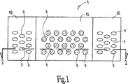
図1及び図2を参照すると、本発明のパターン非結合不織材料4の実施形態が示されている。材料4は、複数の個別の寸法安定化非結合域8、9を定める連続的な結合域6を含む。連続的な結合域6の中には、非繊維性であることが好ましい不織ウェブの繊維又はフィラメントが全体にわたり互いに結合されるか又は定着され、非結合域8、9の中では、該不織繊維又はウェブの繊維又はフィラメントは実質的に又は完全に結合又は定着がなく、その繊維性構造を保持する。
As used herein, the term “hook material” refers to a portion of a mechanical fastening system having an engagement (hook) element, but restricts the form of the engagement element to include a “hook”. Rather, those skilled in the art are unidirectional or bidirectional known to be designed or adapted to engage complementary loop fastening materials, such as the pattern non-bonded nonwoven loop material of the present invention. It is intended to include any form or shape of any engagement element.
Referring to FIGS. 1 and 2, an embodiment of the pattern non-bonded nonwoven material 4 of the present invention is shown. The material 4 includes a
パターン非結合不織材料4は、或る方向において異なる結合パターンを有する複数の領域又はゾーン4A、4Bに分割される。異なる結合パターンは、異なる特有の機能性又は特性を領域4A及び4Bに与える。或る実施形態においては、材料4の中心領域4Aは、最適なフック係合を与える。材料4の外側領域4Bは、中心領域4Aとは異なる特性を与える。或る実施形態においては、異なる特性は不透明性である。或る実施形態においては、異なる特性は色である。或る実施形態においては、異なる特性は引張り強さである。或る実施形態においては、異なる特性は剛性である。他の実施形態においては、材料4の他の特性は、本発明の開示を読むことにより理解されるように、領域4A及び4Bの間で異なる。異なる特性は、外側領域4Bに特有の結合パターンによりもたらされる。或る実施形態においては、外側領域4Bは、材料4が取り付けられる物品、例えば吸収性衣料を超えて外向きに延びる。したがって、外側領域4Bは、それら自体の強度を与えなければならず、中心領域4Aは物品により直接支持されて補強される。さらに、外側領域4Bは、消費者にとって見た目に美しくかつ十分な強度をもっているように見えなくてはならない。本発明は、異なる結合パターンをもつ領域を有することにより、材料4にこれらの特徴を与える。 The pattern non-bonded nonwoven material 4 is divided into a plurality of regions or zones 4A, 4B having different bond patterns in a certain direction. Different binding patterns provide different specific functionality or properties to regions 4A and 4B. In some embodiments, the central region 4A of the material 4 provides optimal hook engagement. The outer region 4B of the material 4 gives different properties than the central region 4A. In some embodiments, the different property is opacity. In some embodiments, the different characteristic is color. In some embodiments, the different property is tensile strength. In some embodiments, the different property is stiffness. In other embodiments, other properties of material 4 are different between regions 4A and 4B, as will be understood by reading the present disclosure. The different characteristics are brought about by the coupling pattern specific to the outer region 4B. In some embodiments, the outer region 4B extends outward beyond the article to which the material 4 is attached, such as an absorbent garment. Thus, the outer region 4B must provide its own strength and the central region 4A is directly supported and reinforced by the article. Further, the outer region 4B must appear to be aesthetically pleasing and have sufficient strength for the consumer. The present invention gives these features to the material 4 by having regions with different bond patterns.
図示実施形態においては、領域4Bは中心領域4Aの外側にかつ該中心領域に隣接して位置させられる。第1非結合域8は、第1の中心領域4Aに形成される。第1に、中心領域4Aは、パターン非結合不織ループ材料である。定義によると、ここで用いられる「パターン非結合不織ループ材料」という用語は、最も単純な形態において、複数の個別の寸法安定化非結合域8を定める連続的な結合域6を含む第1域を有する不織布又はウェブを含むフック・ループ締結システムのためのループ又は雌部品のことを指すことが意図される。この用語は、本発明のループ材料を不織材料だけに限定することを意図するものではなく、むしろ、本発明のループ材料は、例えば、パターン非結合不織布又はウェブがフィルム材料の層に取り付けられるか又は結合された代替的な実施形態において有利に用いることができる。「ループ」という用語を用いることは、本発明のループ材料を、個別の別々に形成された材料のループが、相補的なフック材料のフック要素を受け取って係合するように用いられることに限定するものではなく、むしろ、本発明のループ材料は、個々の繊維又はフィラメントが個別のループに形成されることなく、該繊維又はフィラメントがフック要素を係合するように機能する繊維性不織布又はウェブを含むことを意図する。
In the illustrated embodiment, the region 4B is located outside and adjacent to the central region 4A. The first non-bonding region 8 is formed in the first central region 4A. First, the central region 4A is a pattern non-bonded nonwoven loop material. By definition, the term “patterned non-bonded non-woven loop material” as used herein includes, in its simplest form, a first including a
第2非結合域9は、第2領域4Bに形成される。或る実施形態においては、第2非結合域9は、第1非結合域8に対して異なる特性を有する。例えば、第2非結合域9は、第1非結合域8とは異なる少なくとも1つの寸法を有する。区域9は、区域8の機械の横方向長さより大きい幅方向長さを有することができる。区域9は、区域8の幅方向長さより少ない機械の横方向長さを有することができる。ここで用いられる「機械方向」又はMDという用語は、材料又は布が生成される際の該材料又は布の長さのことを意味する(図3においては左から右へ)。「幅方向」又はCDという用語は、材料又は布の幅、すなわちMDに対してほぼ垂直な該材料又は布の幅のことを意味する。図1に示されるように、機械方向は上から下までである。図1に示されるように、機械の横方向長さは左から右である。区域9は、区域8の機械方向長さより大きい機械方向長さを有することができる。区域9は、区域8の機械方向長さより少ない機械方向長さを有することができる。区域9は、区域8の高さより大きい結合域6の表面から上方に延びる高さを有することができる。或る実施形態においては、区域9は均一である。或る実施形態においては、区域8は均一である。
The second
或る実施形態においては、領域4A及び4Bは、さらに、結合域の量において互いに異なる。結合域は、合計域に対する結合域の百分率として定義される。或る実施形態においては、領域4Aは合計域の約35%の結合域を有する。或る実施形態においては、領域4Bは35%より少ない結合域を有する。或る実施形態においては、領域4Bは25%より少ない結合域を有する。或る実施形態においては、領域4Bは15%より少ない結合域を有する。或る実施形態においては、領域4Bは35%より大きい結合域を有する。或る実施形態においては、領域4Bは40%より大きい結合域を有する。或る実施形態においては、領域4Bは50%より大きい結合域を有する。
図1は、領域4A及び4Bを分離する線を示す。或る実施形態においては、結合域6は連続的であり、領域4Aと4Bとの間で分離されない。したがって、領域4Aと4Bとを分離する線は、材料4上の異なる領域を示すための視覚的な補助に過ぎない。
ここで用いられる「層」又は「ウェブ」という用語は、単独で用いられる場合には、単一要素又は複数の要素という二重の意味を有することができる。ここで用いられる「ラミネート」という用語は、互いに取り付けられるか又は結合された2つ又はそれ以上の材料の層又はウェブから作られた複合材料を意味する。
In some embodiments, regions 4A and 4B further differ from each other in the amount of coupling area. The combined area is defined as the percentage of the combined area relative to the total area. In some embodiments, region 4A has a combined area of about 35% of the total area. In some embodiments, region 4B has less than 35% coupling area. In some embodiments, region 4B has less than 25% coupling area. In some embodiments, region 4B has less than 15% coupling area. In some embodiments, region 4B has a bond area greater than 35%. In some embodiments, region 4B has a bond area greater than 40%. In some embodiments, region 4B has a bond area greater than 50%.
FIG. 1 shows a line separating regions 4A and 4B. In some embodiments, the
The term “layer” or “web” as used herein can have the dual meaning of a single element or multiple elements when used alone. The term “laminate” as used herein refers to a composite material made from two or more layers or webs of materials attached or bonded together.
再び図1及び図2を参照すると、パターン非結合不織ループ材料の領域4Aは、一般に、本発明により形成されると、相補的なフック材料のフックを受け取って係合するのに好適な布又はウェブのいずれかとして説明される。ここで用いられる「不織布」又は「不織ウェブ」とは、相互に織り込まれているが、編布におけるように識別可能になっていない個々の繊維又はフィラメントの構造を持つウェブのことをいう。しかしながら、本発明は不織布及びウェブの概念において説明されるが、ここに説明されるプロセス及び装置を用いることにより、複数の個別の非結合域を定める連続的な結合域のパターンを、その少なくとも1つの表面上に形成することができる適切な材料で形成された織物及び/又は編物を寸法安定化できることに注目されたい。 Referring again to FIGS. 1 and 2, the region 4A of patterned non-bonded nonwoven loop material is generally a fabric suitable for receiving and engaging hooks of complementary hook material when formed in accordance with the present invention. Or described as either web. As used herein, “nonwoven” or “nonwoven web” refers to a web having a structure of individual fibers or filaments that are interwoven but not distinguishable as in a knitted fabric. However, although the invention is described in the concept of nonwovens and webs, by using the processes and apparatus described herein, a pattern of continuous bonded areas defining a plurality of individual unbonded areas can be obtained. Note that woven and / or knitted fabrics formed of suitable materials that can be formed on one surface can be dimensionally stabilized.
市販の熱可塑性ポリマー材料は、パターン非結合不織材料4を形成する繊維又はフィラメントを作るのに有利に用いることができる。ここで用いられる「ポリマー」という用語は、単独重合体と、例えば、ブロック共重合体、グラフト共重合体、ランダム共重合体、及び交互共重合体、三元共重合体等のような共重合体と、それらの配合物及び変成物を含むが、これらに限られるものではない。さらに、特に限定されていない限り、「ポリマー」という用語は、これらに限られるものではないが、アイソタクチック対称、シンジオタクチック対称、及びアタクチック対称を含む、材料の可能性のある全ての幾何学的形状をも含む。ここで用いられる「熱可塑性ポリマー」、又は「熱可塑性ポリマー材料」という用語は、高温に曝された時に軟化し、室温まで冷却された時には実質的に元の状態に戻る長鎖ポリマーのことをいう。例示的な熱可塑性材料は、この限りではないが、ポリ塩化ビニル、ポリエステル、ポリアミド、ポリフルオロカーボン、ポリオレフィン、ポリウレタン、ポリスチレン、ポリエチレン、ポリビニルアルコール、カプロラクタム、及び上記のもののコポリマーを含む。パターン非結合不織材料4を作るのに用いられる繊維又はフィラメントは、適切な形態のいずれかを有することができ、当該技術分野では公知である中空の又は中実の、直線状の又はクリンプ加工された、単一成分、二成分、多成分、二要素又は多要素繊維又はフィラメント、及びこうした繊維及び/又はフィラメントのブレンド又は混合物を含むことができる。 Commercially available thermoplastic polymer materials can be advantageously used to make the fibers or filaments that form the patterned non-bonded nonwoven material 4. As used herein, the term “polymer” refers to homopolymers and copolymers such as block copolymers, graft copolymers, random copolymers, and alternating copolymers, terpolymers, and the like. Including, but not limited to, coalescence and blends and modifications thereof. Further, unless otherwise limited, the term “polymer” includes, but is not limited to, all possible geometries of a material, including isotactic, syndiotactic, and atactic symmetries. Also includes geometric shapes. As used herein, the term "thermoplastic polymer" or "thermoplastic polymer material" refers to a long chain polymer that softens when exposed to high temperatures and substantially returns to its original state when cooled to room temperature. Say. Exemplary thermoplastic materials include, but are not limited to, polyvinyl chloride, polyester, polyamide, polyfluorocarbon, polyolefin, polyurethane, polystyrene, polyethylene, polyvinyl alcohol, caprolactam, and copolymers of the foregoing. The fibers or filaments used to make the pattern non-bonded nonwoven material 4 can have any suitable form and are hollow or solid, straight or crimped as known in the art. Single component, bicomponent, multicomponent, bicomponent or multicomponent fibers or filaments, and blends or mixtures of such fibers and / or filaments.
本発明のパターン非結合不織材料として用いることができる不織ウェブは、スパンボンド工程、空気堆積工程、又はボンデッド・カーデッド・ウェブ形成行程を含む種々の既知の形成工程により形成することができる。すべてのこのような不織ウェブは、既知の不織ウェブ結合技術を用いて予め結合して、本発明のパターン非結合方法及び装置を用いて後続して結合することができ、或いは、このような不織ウェブは、本発明のパターン非結合方法及び装置を用いて結合だけすることができる。 Nonwoven webs that can be used as the patterned non-bonded nonwoven material of the present invention can be formed by a variety of known forming processes including spunbond processes, air deposition processes, or bonded carded web forming processes. All such nonwoven webs can be pre-bonded using known non-woven web bonding techniques and subsequently bonded using the pattern non-bonding method and apparatus of the present invention, or as such Such nonwoven webs can only be bonded using the pattern unbonding method and apparatus of the present invention.
スパンボンド不織ウェブは、メルトスパンフィラメントから作られる。ここで用いられる「メルトスパンフィラメント」という用語は、溶融した熱可塑性材料を、紡糸口金の複数の微細な普通は円形の毛細管からフィラメントとして押し出し、次いで、押し出されたフィラメントの直径を、例えば、非抽出的又は抽出的流体引き出しか又は他の周知のスパンボンド機構によって急速に縮小することにより形成される小直径の繊維及び/又はフィラメントのことをいう。スパンボンド不織ウェブの製造は、アッペル他に付与された米国特許第4,340,563号、ドーシュナー他に付与された米国特許第3,692,618号、マツキ他に付与された米国特許第3,802,817号、Kinneyに付与された米国特許第3,338,992号及び第3,341,494号、ハートマンに付与された米国特許第3,502,763号、レビーに付与された米国特許第3,276,944号、ピーターソンに付与された米国特許第3,502,538号、及びドーボー他に付与された米国特許第3,542,615号に記載されており、これらの特許の全ては引用によりここに組み入れられる。スパンボンド工程によって形成された溶融紡糸フィラメントは、通常は連続しており、7ミクロンより大きい、より特定的には約10から30ミクロンまでの間の直径を有する。繊維又はフィラメント直径の別の頻繁に用いられる表現はデニールであり、これは、繊維又はフィラメントの9000メートル当たりのグラム数として定義される。スパンボンドフィラメントは、普通は、移動する小孔のあるベルト又は形成ワイヤの上に堆積され、そこでそれらはウェブを形成する。スパンボンドフィラメントは、一般的には、集積面の上に堆積されたときには粘着性がない。 Spunbond nonwoven webs are made from melt spun filaments. As used herein, the term “melt-spun filament” refers to extruding molten thermoplastic material as a filament from a plurality of fine, normally circular capillaries of a spinneret, and then determining the diameter of the extruded filament, eg, non- Refers to small diameter fibers and / or filaments formed by rapid shrinkage by extractive or extractive fluid draw or other known spunbond mechanisms. The production of spunbond nonwoven webs is described in U.S. Pat. No. 4,340,563 to Appel et al., U.S. Pat. No. 3,692,618 to Dorschner et al., U.S. Pat. 3,802,817, US Pat. Nos. 3,338,992 and 3,341,494 granted to Kinney, US Pat. No. 3,502,763 granted to Hartman, granted to Levy U.S. Pat. No. 3,276,944, U.S. Pat.No. 3,502,538 to Peterson, and U.S. Pat. All of the patents are incorporated herein by reference. Melt spun filaments formed by the spunbond process are usually continuous and have a diameter greater than 7 microns, more particularly between about 10 and 30 microns. Another frequently used expression for fiber or filament diameter is denier, which is defined as grams per 9000 meters of fiber or filament. Spunbond filaments are usually deposited on a moving, perforated belt or forming wire where they form a web. Spunbond filaments are generally not tacky when deposited on a collection surface.
スパンボンド布は、典型的には、さらに加工して完成品にする際の過酷さに耐えるのに十分なだけの一体性をウェブに与えるために、製造される際に或る方法で直ちに安定化され又は強化され(予め結合され)る。この安定化(予め結合する)段階は、熱によって又はより一般的には圧縮ロールによって活性化される液体又は粉末としてフィラメントに適用される接着剤を使用することによって達成可能である。ここで用いられる「圧縮ロール」という用語は、ウェブに後で処理するのに十分なだけの一体性を与えるために、通気結合、熱結合、超音波結合等といった第2結合工程の比較的強い結合ではなく、製造直後の溶融紡糸フィラメント、特にスパンボンドウェブを処理する1つの手段として、ウェブを圧縮するのに用いられるウェブの上の及び下のローラの組を意味する。圧縮ロールは、ウェブの自己付着性、ひいてはその一体性を高めるために、ウェブを僅かに圧搾するものである。 Spunbond fabrics typically stabilize in some way as they are manufactured in order to provide the web with sufficient integrity to withstand the rigors of further processing into finished products. Or strengthened (pre-bonded). This stabilization (pre-bonding) step can be achieved by using an adhesive applied to the filaments as a liquid or powder that is activated by heat or more generally by a compression roll. As used herein, the term “compressed roll” is a relatively strong second bonding process such as vent bonding, thermal bonding, ultrasonic bonding, etc., to give the web enough integrity for subsequent processing. As a means of treating melt spun filaments, particularly spunbond webs, immediately after manufacture, rather than bonding, means a set of rollers above and below the web used to compress the web. The compression roll squeezes the web slightly in order to increase the self-adhesion of the web and thus its integrity.
予め結合する段階を実行する別の手段は、引用によりここに組み入れられる1994年12月22日付けの本発明の譲受人に譲渡された米国特許第5,707,468号に詳細に記載されるような高温エアナイフを使用するものである。手短に述べると、「高温エアナイフ」という用語は、さらなる処理のためにウェブに十分な団結性を付与する、すなわちウェブの剛性を増大させるために、製造直後の溶融紡糸フィラメント、特にスパンボンドウェブを予め結合する工程を意味するが、上述されたような比較的強い二次的な結合工程ではない。高温エアナイフは、加熱された空気流を、非常に高い流速、通常は約300から約3000メートル毎分(m/分)、又はより特定的には約900から約1500m/分で形成直後の不織ウェブに向けて集中させる装置である。空気温度は、普通は、ウェブに用いられる少なくとも1つのポリマーの溶融点の範囲内であり、スパンボンドに通常用いられる熱可塑性ポリマーにおいては、一般的には約90℃から約290℃までの間である。空気温度、速度、圧力、体積その他の因子の制御は、ウェブに対する損傷を避ける一方で、その団結性を高めるのを助ける。高温エアナイフの集中された空気流は、ウェブに向かう加熱空気の出口として働く幅約3から約25ミリメートル(mm)まで、特に約9.4mmの少なくとも1つのスロットによって配列され及び向けられ、スロットは、ウェブのほぼ幅全体の上をほぼ断面方向に延びる。他の実施形態においては、互いに隣接して配置された又は僅かな隙間によって分離された複数のスロットが存在してもよい。少なくとも1つのスロットは、普通は、必ずというわけではないが連続しており、例えば近接する間隔をおいて配置された孔から構成することができる。高温エアナイフは、スロットを出る前の加熱空気を分散させ収容するプレナムを有する。高温エアナイフのプレナム圧力は、普通は約2から約22mmHgまでの間であり、高温エアナイフは、形成面上から、約6.35mmから約254mmまでの間、より特定的には約19.05から約76.20mmまでの間の距離のところに位置される。特定的な実施形態においては、断面方向の流れのための高温エアナイフのプレナムの断面積(すなわち、機械方向のプレナムの断面積)は、スロット出口面積全体の少なくとも2倍である。その上にスパンボンドポリマーが形成される小孔のあるワイヤは、通常は高速で移動するので、ウェブの特定の部分のいずれかが高温エアナイフから放出された空気に露出される時間は、より長い滞留時間を有する通気結合工程とは対照的に、典型的には0.1秒より短く、一般的には約0.01秒より短い。高温エアナイフ工程は、大きな可変性を有し、空気温度、速度、圧力、及び体積、スロット又は孔の配置、密度及び寸法、並びに高温エアナイフ・プレナムとウェブとを分離する距離を含む多くの因子を制御する。 Another means of performing the pre-binding step is described in detail in US Pat. No. 5,707,468 assigned to the assignee of the present invention on December 22, 1994, incorporated herein by reference. Such a hot air knife is used. Briefly, the term “hot air knife” refers to melt-spun filaments, especially spunbond webs, immediately after manufacture to impart sufficient cohesion to the web for further processing, i.e. to increase web stiffness. This means a pre-bonding process, but not a relatively strong secondary bonding process as described above. Hot air knives produce a heated air stream at a very high flow rate, usually from about 300 to about 3000 meters per minute (m / min), or more particularly from about 900 to about 1500 m / min. It is a device that concentrates on the woven web. The air temperature is usually within the melting point of at least one polymer used for the web, and typically between about 90 ° C. and about 290 ° C. for thermoplastic polymers commonly used for spunbonds. It is. Control of air temperature, speed, pressure, volume, and other factors helps to increase the integrity while avoiding damage to the web. The concentrated air flow of the hot air knife is arranged and directed by at least one slot having a width of about 3 to about 25 millimeters (mm), particularly about 9.4 mm, which serves as an outlet for heated air toward the web, , Extending substantially in the cross-sectional direction over substantially the entire width of the web. In other embodiments, there may be a plurality of slots arranged adjacent to each other or separated by a slight gap. The at least one slot is usually, but not necessarily, continuous and can be composed of, for example, closely spaced holes. The hot air knife has a plenum that disperses and houses the heated air prior to exiting the slot. The plenum pressure of the hot air knife is usually between about 2 and about 22 mmHg, and the hot air knife is between about 6.35 mm and about 254 mm, more specifically from about 19.05, on the forming surface. Located at a distance between about 76.20 mm. In a particular embodiment, the hot air knife plenum cross-sectional area for cross-sectional flow (ie, the cross-sectional area of the machine direction plenum) is at least twice the total slot exit area. The small hole wire on which the spunbond polymer is formed usually moves at high speed, so the time that any particular part of the web is exposed to the air released from the hot air knife is longer In contrast to a vent bonding process with a residence time, it is typically less than 0.1 seconds and generally less than about 0.01 seconds. The hot air knife process has great variability and has many factors including air temperature, velocity, pressure, and volume, slot or hole placement, density and dimensions, and the distance separating the hot air knife plenum and the web. Control.
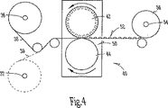
スパンボンド工程はまた、例えば、並列(又は鞘/芯)線状低密度ポリエチレン/ポリプロピレン・スパンボンド二成分フィラメントからの二成分スパンボンド不織ウェブを形成するのに用いることができる。こうした二成分スパンボンド不織ウェブを形成するのに適した工程は、Pike他の米国特許第5,418,045号に記載されており、該特許は引用によりその全体がここに組み入れられる。この文書の図3を参照すると、このような二成分フィラメントを形成する工程ライン10、及びその結果もたらされるウェブは、ホッパ14a及び14bのそれぞれから、押出導管16a及び16bのそれぞれを通して二成分紡糸口金18に、ポリエチレン及びポリプロピレンの両方を別々に供給するための一対の押出機12a及び12bを用いることを含む。二成分フィラメントを生成する紡糸口金は、当業者においてよく知られており、したがって、ここでは詳細に説明しない。一般に、紡糸口金18は、スピンパックを含むハウジングを含み、これは、高溶融温度ポリマーと低溶融温度ポリマーとを別々に紡糸口金における繊維形成開口部に指向するための流路を生成するように配置された開口部のパターンを有する垂直方向に重ねられた複数のプレートを含むものである。紡糸口金18は、1つ又はそれ以上の列に配置された開口部を有し、該開口部は、ポリマーが該紡糸口金を通って押し出されるときに下向きに延びるフィラメントのカーテンを形成する。クエンチガス源20が紡糸口金18の出口から下流側に位置させられる。フィラメントのカーテンが紡糸口金18から出て行くと、これらは源20からのクエンチガスと接触する。クエンチガスは、フィラメントカーテンの一方の側又は両側(図示せず)に衝突し、これにより少なくとも部分的に該フィラメントを急冷して、紡糸口金18から延びるフィラメントにおいて潜在的に螺旋状のクリンプが作られる。典型的には、急冷空気は、1分当たり約30から約120メートルまでの速度、及び約7℃から約32℃までの温度で、フィラメントの長さに対してほぼ垂直に指向される。
The spunbond process can also be used, for example, to form a bicomponent spunbond nonwoven web from side-by-side (or sheath / core) linear low density polyethylene / polypropylene spunbond bicomponent filaments. Suitable processes for forming such bicomponent spunbond nonwoven webs are described in US Pat. No. 5,418,045 to Pike et al., Which is hereby incorporated by reference in its entirety. Referring to FIG. 3 of this document, a process line 10 for forming such a bicomponent filament, and the resulting web, is fed from a hopper 14a and 14b, respectively, through a
急冷されたフィラメントを受け取るように、繊維引き出し装置又はアスピレータ22が紡糸口金18の下に、例えば該紡糸口金の下流側に位置させられる。溶融紡糸ポリマーにおいて用いられる繊維引き出し装置又はアスピレータは当業者に周知である。この工程に用いるのに好適な例示的な繊維引き出し装置は、マツキ他に付与された米国特許第3,802,817号に示される種類の線形繊維アスピレータ、及びドーシュナー他に付与された米国特許第3,692,618号、及びDavies他に付与された米国特許第3,423,266号に示される種類の抽出ガンを含み、これらの開示は引用によりここに組み入れられる。繊維引き出し装置は、一般には、細長い通路を有し、吸引ガスが該通路を通って流れることにより、フィラメントがこれを通して引き出される。吸引ガスは、フィラメントのポリマーと不利に相互作用しない空気のようないずれのガスであってもよい。供給ユニット24は、吸引ガスを繊維引き出し装置22に供給する。吸引ガスが、繊維引き出し装置22を通して急冷されたフィラメント及び周囲空気を引き出すと、該フィラメントは、その中の潜在的なクリンピングを作動させるのに必要とされる温度にまで加熱される。フィラメント内の潜在的なクリンピングを作動させるのに必要とされる温度は、摂氏約43度から、この場合においてはポリエチレンである低溶融コンポーネントポリマーの融点より少ない最大値までの範囲に及ぶ。一般に、より高い空気温度は、フィラメントの1ユニット長さ当たりより多い数のクリンプを生成する。或いは、紡糸口金18を出て行くフィラメントのカーテンは、周囲温度で引き出すことができ、結果としてほぼ真っ直ぐのウェブであるか又はクリンプされていないスパンボンドフィラメントを形成するようになる。
A fiber drawing device or
引き出されてクリンプされたフィラメントは、繊維引き出し装置22を出て行き、不規則な方法により、形成表面の下に置かれた真空装置30の助けによって、連続的な形成表面26の上に堆積される。真空の目的は、フィラメントの望ましくない散乱を排除すること、及び該フィラメントを形成表面26上に導いて、均一な非結合の二成分フィラメントの不織ウェブを形成するようにすることである。所望であれば、結果としてもたらされるウェブを、該ウェブが、ここに説明されるように、本発明のパターン非結合組立体40に曝される前に、圧縮ローラ32又は高温エアナイフ(図示せず)により軽く圧縮することができる。
本発明を作る際に用いられる好適な不織ウェブは、さらに、典型的には非連続的なステープル繊維で形成されるボンデッド・カーデッド・ウェブ及び空気堆積ウェブから作ることができる。その少なくとも一部が、有利にはその複数の部分が結合域の中に延びる非結合域内の個々の繊維の数を最大にするために、個別の非結合域の大きさ及び密度を適切に適応させるように、このような不織ウェブを用いて本発明のパターン非結合不織ループ材料を作る際には、注意が必要である。
The drawn and crimped filaments exit the
Suitable nonwoven webs used in making the present invention can further be made from bonded carded webs and air-laid webs typically formed of discontinuous staple fibers. Appropriately adapt the size and density of the individual non-bonded areas, at least in part, to maximize the number of individual fibers in the non-bonded areas, preferably where the parts extend into the bonded area As such, care must be taken when using such nonwoven webs to make the pattern unbonded nonwoven loop material of the present invention.
ボンデッド・カーデッド・ウェブは、普通は梱で購入されるステープル繊維から作られる。梱は、繊維を分離するピッカー内に置かれる。次に、繊維は、コーミング装置又はカーディング装置を通して送られ、ステープル繊維をさらに分解し機械方向に位置合わせして、ほぼ機械方向に方位付けられた繊維性不織ウェブが形成されるようになる。ウェブが形成されると、上述のように予め結合されることになる。
空気堆積工程は、繊維性の不織ウェブを形成することができる別のよく知られた工程である。空気堆積工程では、約6から約19ミリメートル(mm)までの範囲の一般的な長さを持つ小繊維の束が、分離されて空気中に浮遊させられ、次いで普通は真空の助けによって成形スクリーン上に堆積される。次いで不規則に堆積された繊維が、既知の結合技術を用いて、互いに予め結合されることになる。
Bonded carded webs are usually made from staple fibers purchased in bundles. The package is placed in a picker that separates the fibers. The fibers are then fed through a combing or carding device to further disassemble and align the staple fibers in the machine direction to form a fibrous nonwoven web oriented in the generally machine direction. . Once the web is formed, it will be pre-bonded as described above.
The air deposition process is another well known process that can form a fibrous nonwoven web. In the air deposition process, a bundle of fibrils with a typical length ranging from about 6 to about 19 millimeters (mm) is separated and suspended in air, then usually shaped screen with the help of a vacuum. Deposited on top. The irregularly deposited fibers will then be prebonded together using known bonding techniques.
不織ウェブが形成された後、予め結合されたか又は非結合のウェブは、好適な工程及び装置40を通過して、本発明のパターン非結合不織材料4が形成されるようになる。ここで図4及び図5を参照すると、本発明のパターン非結合不織材料4を形成する工程及び装置がここで説明される。図4においては、本発明のパターン非結合不織材料は、全体を40で表される。この装置40は、第1のウェブ38についての第1ウェブのアンワインド36を含む。任意に、多層のパターン非結合ラミネートを形成する際に用いることができる、付加的なウェブ又は層39についての1つ又はそれ以上の付加的なウェブのアンワインド37(破線で示される)を含む。図4において示される装置はウェブのアンワインド36を示すが、パターン非結合組立体40は、ここで説明され図3に示される不織布形成装置と共に、連続的な(インライン)工程に置くことができることを理解されたい。ここで用いられる「パターン非結合組立体」という用語は、存在する結合部、もしある場合にはウェブ38を分解する、破壊する、又は除去する装置として解釈されるものではなく、むしろ、パターン非結合組立体は、ウェブの特定の区域における繊維又はフィラメント形成ウェブ38を連続的に結合するか又は定着して、ここではそれぞれ結合域及び非結合域と呼ばれる区域のようなウェブの他の特定の区域におけるウェブの繊維又はフィラメントの結合又は定着を阻止する装置のことをいう。 After the nonwoven web is formed, the prebonded or unbonded web is passed through suitable processes and equipment 40 to form the patterned nonbonded nonwoven material 4 of the present invention. Referring now to FIGS. 4 and 5, the process and apparatus for forming the patterned non-bonded nonwoven material 4 of the present invention will now be described. In FIG. 4, the patterned non-bonded nonwoven material of the present invention is generally designated 40. The device 40 includes a first web unwind 36 for a first web 38. Optionally, including one or more additional web unwinds 37 (shown in dashed lines) for additional webs or layers 39 that can be used in forming a multi-layer pattern unbonded laminate. . Although the apparatus shown in FIG. 4 shows a web unwind 36, the pattern unbonded assembly 40 can be placed in a continuous (in-line) process with the nonwoven forming apparatus described herein and shown in FIG. I want you to understand. As used herein, the term “pattern unbonded assembly” is not to be construed as a device that disassembles, breaks, or removes the existing bond, if any, the web 38; The bonding assembly continuously bonds or anchors the fibers or filament-forming webs 38 in specific areas of the web, such as other specific areas of the web, such as areas referred to herein as bonded areas and unbonded areas, respectively. Refers to a device that prevents the bonding or fusing of web fibers or filaments in a zone.
第1ウェブ38(又は1つのアンワインドだけが用いられる場合には単純に「ウェブ」)は、アンワインド36から取り外されて、共に、例えば電気モータ(図示せず)のような通常の駆動手段により駆動される、例えば回転される、第1の又はパターンロール42及び第2の又はアンビルロール44を含むパターン非結合組立体40の中に通される。パターンロール42は、中心領域4Aを形成する中心表面45Aと、外側領域4Bを形成する複数の外側表面45Bを含む。パターンロール42は、例えば、使用中にロール上の磨耗を減らす硬化金属又は鋼のような耐久性のある適当な材料のいずれかで形成することができる右の円形シリンダである。パターンロール42の外面は、中心表面45Aにおいてランド域46Aの第1パターンを有する。ランド域46Aは、第1の複数の個別の凹部又はアパーチャ48Aを定める。ランド域46Aは、如何なる適当な耐久性のある材料でも形成することができる直円柱シリンダでもある、対向して位置させられたアンビルロール44の滑らかな又は平坦な外面とニップを形成するように設計される。ランド域46A及びアパーチャ48Aは、パターン非結合材料4の中心領域4Aを形成する。
The first web 38 (or simply “web” if only one unwind is used) is removed from the
パターンロール42において、凹部48Aの大きさ、形状、数、及び構成は、これにより形成されるパターン非結合不織ループ材料の特定の最終用途要求を満たすように変えることができる。結果としてもたらされるループ材料において、繊維抜けの発生を減らすためには、パターンロール42の中心表面45Aにおける凹部の大きさは、非結合域を形成するフィラメント又は繊維の長さ全体が単一の非結合域の範囲内にあるという可能性を減らすように寸法決めするべきである。異なる方法で述べると、繊維長さは所定の繊維又はフィラメントの長さ全体が単一の非結合域の範囲内にあるという可能性を減らすように選択されるべきである。一方、パターンロール42における凹部48Aの大きさ、及びこれによりパターン非結合不織材料4の中心領域4Aに形成される非結合域8の大きさを制限することの望ましさは、該非結合域8が相補的なフック材料のフック要素について必要とされる係合域を与えるのに十分な大きさを有する必要性により相殺される。この文書の図5に示され、約0.050インチ(約0.127cm)から約0.250インチ(約0.635cm)までの範囲に及ぶ平均直径、より特定的には、約0.130インチ(約0.330cm)から約0.160インチ(約0.406cm)までの範囲に及ぶ平均直径を有し、パターンロール42の最も外側の表面から測定した深さが少なくとも約0.020インチ(約0.051cm)、より特定的には少なくとも約0.060インチ(0.152cm)である円形凹部48Aは、本発明のパターン非結合不織材料を形成するのに好適であると考えられる。図5に示されるように、パターンロール42における凹部48Aは円形であるが、閉曲線、楕円形、多角形、正方形、ひし形などのような他の形状を有利に用いることができる。
In the
パターンロール42における凹部48Aの数又は密度は、さらに、不当に連続的な結合域の大きさを制限して、繊維抜けの発生の増加を生じさせることなく、必要な量の係合域を与えるように選択することができる。1平方センチメートル(cm2)当たり約1.0個の凹部から約25.0個の凹部/cm2までの範囲、より特定的には約5.0個から約7.0個の凹部/cm2までの範囲にある凹部密度を利用して、本発明のパターン非結合材料4の中心領域4Aを有利に形成するようにすることができる。
さらに、個々の凹部48A間の間隔は、繊維抜けを減らすものとなる連続的な結合域により占められるパターン非結合材料の部分を過度に減らすことなく、結果としてもたらされるパターン非結合材料4の中心領域4Aのフック係合機能を高めるように選択することができる。図示実施形態について好適な凹部の間隔は、機械方向及び幅方向において、中心線間が約0.13インチ(約3.30mm)から0.22インチ(約5.59mm)までに及ぶものとすることができる。
The number or density of the recesses 48A in the
Further, the spacing between the individual recesses 48A is such that the center of the resulting pattern unbonded material 4 does not unduly reduce the portion of the pattern unbonded material that is occupied by the continuous bond area that reduces fiber shedding. Selection can be made to enhance the hook engagement function of region 4A. The preferred recess spacing for the illustrated embodiment should range from about 0.13 inches to about 0.22 inches in the machine and width directions. be able to.
パターンロール42における凹部48Aの特定の配置又は構成は、凹部の大きさ、形状、及び密度と組み合わせて表面の一体性及び耐久性、及びフック要素の係合が達成されている限り、重要なものであるとして考えられない。例えば、図5に示されるように、個々の凹部48Aは交互の列に配置される(図1も参照のこと)。他の異なる構成は、本発明の範囲内にあると考えられる。
連続的なランド域46Aにより占められるパターンロール42の最も外側の表面の一部を同様に修正して、パターン非結合材料の意図される最終用途の適用例を満たすようにすることができる。連続的なランド域46Aによりパターン非結合不織材料4の中心領域4Aに与えられた結合の程度は、結合域6により占められる領域4Aのパターン非結合不織材料の少なくとも1つの合計平面域の部分を指す、結合域百分率として表すことができる。一般的に述べると、本発明のパターン非結合不織領域4Aを形成するのに好適な結合域百分率における下限は、繊維抜けがパターン非結合材料の表面の一体性及び耐久性を過度に減らす点である。要求される結合域百分率は、不織ウェブが単層であっても又は多層の繊維構造であっても、該不織ウェブが非結合であっても又はパターン非結合組立体などの中に通される前に予め結合されていても、該不織ウェブの繊維又はフィラメントを形成するのに用いられるポリマー材料の種類を含む多数の因子により影響される。約25%から約50%までの範囲、より特定的には、約36%から約50%までの範囲に及ぶ結合域百分率を有するパターン非結合不織材料が好適であると見出された。
The particular arrangement or configuration of the recesses 48A in the
A portion of the outermost surface of the pattern roll 42 occupied by the continuous land area 46A can be similarly modified to meet the intended end use application of the pattern unbonded material. The degree of bonding imparted to the central region 4A of the patterned non-bonded nonwoven material 4 by the continuous land area 46A is that of at least one total planar area of the patterned non-bonded nonwoven material in the region 4A occupied by the
パターンロール42は、少なくとも一方が中心表面45Aの各々の端部から縦方向に配置された少なくとも2つの外面45Bを含む。パターンロール42の外面45Bは、ランド域46Bの第2のパターンを含む。ランド域46Bは、第2の複数の個別の凹部又はアパーチャ48Bを定める。ランド域46Bは、対向して位置されたアンビルロール44の滑らかな又は平坦な外面とニップ50を形成するように設計される。ランド域46B及びアパーチャ48Bは、パターン非結合材料4の外側領域4Bを形成する。
The pattern roll 42 includes at least two outer surfaces 45B, at least one of which is arranged in the longitudinal direction from each end of the central surface 45A. The outer surface 45B of the
パターンロール42における凹部48Bの大きさ、形状、数、及び構成は、これにより形成されるパターン非結合不織域4Bの特定の最終用途要求を満たすように変えることができる。パターンロール42の外面における凹部48Bの大きさは、非結合域を形成するフィラメント又は繊維の長さ全体が単一の非結合域9の範囲内にあるという可能性を減らすように寸法決めされる。異なる方法で述べると、繊維長さは所定の繊維又はフィラメントの長さ全体が単一の非結合域の範囲内にあるという可能性を減らすように選択されるべきである。一般には、この文書の図5に示されるような楕円形の凹部48Bは、約0.050インチ(約0.127cm)から約0.250インチ(約0.635cm)までの範囲に及ぶ値より少ない平均主軸を有する。或る実施形態においては、主軸は、約0.130インチ(約0.330cm)から約0.160インチ(約0.406cm)までの範囲に及ぶ値より少ない。楕円形の凹部48Bは、約0.050インチ(約0.127cm)から約0.250インチ(約0.635cm)までの範囲に及ぶ値より少ない平均短軸を有する。或る実施形態においては、短軸は、0.130インチ(0.330cm)から約0.160インチ(0.406cm)までの範囲に及ぶ値より少ない。或る実施形態においては、凹部48Bの直径、幅、主軸、又は短軸は、凹部48Aの直径より少ない。楕円形の凹部48Bは、パターンロール42の最も外側の表面から測定した深さが少なくとも約0.020インチ(約0.051cm)、より特定的には、少なくとも約0.060インチ(0.152cm)であるものが、本発明のパターン非結合不織材料を形成するのに好適であると考えられる。或る実施形態においては、凹部48Bの深さは、凹部48Aの深さより少ない。図5に示されるパターンロール42の凹部48Bは楕円形であるが、閉曲線、円形、多角形、正方形、ひし形などのような他の形状を有利に用いることができる。
The size, shape, number and configuration of the recesses 48B in the
パターンロール42における凹部48Aの数又は密度は、さらに、外側材料域4Bに必要な特性をもたらすように選択することができる。パターンロールの外面45Bは、1平方センチメートル(cm2)当たり約1.0個の凹部から約25.0個の凹部/cm2までの範囲、より特定的には約5.0から約7.0個の凹部/cm2までの範囲にある凹部密度を利用して、本発明のパターン非結合材料4の外側領域4Bを有利に形成するようにすることができる。或る実施形態においては、外面45Bの凹部密度は、中心表面45Aの凹部密度より少ない。さらに、個々の凹部48B間の間隔は、材料4の外側域4Bの必要な特性を高めるか及び/又はもたらすように選択することができる。或る実施形態において好適な凹部間の間隔は、機械方向及び/又は幅方向のいずれにおいても、中心線間が約0.13インチ(約3.30mm)から0.22インチ(約5.59mm)までに及ぶものとすることができる。或る実施形態においては、外面45Bにおける凹部間の間隔は、中心表面45Aにおける凹部間の間隔より大きい。
パターンロール42における凹部48Bの特定の配置又は構成は、凹部の大きさ、形状、及び密度と組み合わせて表面の一体性及び耐久性、及び特性が達成されている限り、重要なものであるとして考えられない。例えば、図5に示されるように、個々の凹部48Bは交互の列に配置される(図1も参照のこと)。他の異なる構成は、本発明の範囲内にあると考えられる。
The number or density of the recesses 48A in the
The particular arrangement or configuration of the recesses 48B in the
連続的なランド域46Bにより占められるパターンロール42の最も外側の表面の一部を同様に修正して、パターン非結合材料の意図され最終用途の適用例、特に、パターン非結合外側領域4Bの最終用途の適用例を満たすようにすることができる。連続的なランド域46Bによりパターン非結合不織材料4の外側領域4Bに与えられた結合の程度は、結合域46Bにより占められるパターン非結合不織ループ材料4、例えば、領域4B(図1参照)の少なくとも1つの合計平面域の部分を指す、結合域百分率として表すことができる。一般的に述べると、本発明のパターン非結合不織領域4Bを形成するのに好適な結合域百分率における下限は、繊維抜けがパターン非結合材料4の表面の一体性及び耐久性を過度に減らす点である。要求される結合域百分率は、不織ウェブが単層であっても又は多層の繊維構造であっても、該不織ウェブが非結合であっても又はパターン非結合組立体などの中に通される前に予め結合されていても、該不織ウェブの繊維又はフィラメントを形成するのに用いられるポリマー材料の種類を含む多数の因子により影響される。約25%から約50%までの範囲、より特定的には、約36%から約50%までの範囲に及ぶ結合域百分率を有するパターン非結合不織材料が好適であると見出された。或る実施形態においては、領域4Bの結合域百分率は、中心領域4Aの結合域百分率より少ない。例えば、領域4Bの結合域百分率は、中心領域4Aの結合域百分率が50%であるか又はそれより大きい場合には、50%より少ない。領域4Bの結合域百分率は、中心領域4Aの結合域が36%であるか又はそれより大きい場合には、36%より少ない。 A portion of the outermost surface of the pattern roll 42 occupied by the continuous land area 46B is similarly modified to provide an intended end use application of the pattern unbonded material, particularly the end of the pattern unbonded outer region 4B. It can be made to satisfy the application example of a use. The degree of bonding provided by the continuous land area 46B to the outer region 4B of the patterned non-bonded nonwoven material 4 is determined by the pattern non-bonded non-woven loop material 4 occupied by the bonding area 46B, eg, the region 4B (see FIG. 1). ) At least one portion of the total planar area. Generally speaking, the lower limit on the percentage of bonded area suitable for forming the pattern non-bonded nonwoven region 4B of the present invention is that fiber loss excessively reduces the surface integrity and durability of the pattern non-bonded material 4. Is a point. The required bonded area percentage may be passed through a single layer or multi-layered fiber structure, whether the nonwoven web is unbonded, pattern unbonded assemblies, etc. Even if it is pre-bonded before it is applied, it is affected by a number of factors, including the type of polymeric material used to form the fibers or filaments of the nonwoven web. Patterned non-bonded nonwoven materials having a bond area percentage ranging from about 25% to about 50%, more specifically from about 36% to about 50% have been found to be suitable. In some embodiments, the percentage of bound area in region 4B is less than the percentage of bound area in central region 4A. For example, the bond area percentage of region 4B is less than 50% if the bond area percentage of center region 4A is 50% or greater. The percentage of coupling area in region 4B is less than 36% when the coupling area of central region 4A is 36% or greater.
本発明においては、外側領域4Bにおけるパターン非結合域9は、中心のループファスナ領域4Aにおけるパターン非結合域8と異なることが好ましい。或る実施形態においては、区域9と区域8との間の違いは、それらの物理的寸法を含む。区域9と区域8との間の違いは、領域4B及び4Aのそれぞれがパターンローラ42及びアンビルローラ44の作動により生成された異なる特性を有するようになることをもたらす。或る実施形態においては、中心領域4Aは、外側領域4Bより不透明である。或る実施形態においては、外側領域4Bは、中心領域4Aより不透明である。不透明性は、さらに、その領域を人間の目に対してより不透明に示すことになる色の変位のことを指すことが認識される。或る実施形態においては、中心領域4Aは外側領域4Bより堅い。或る実施形態においては、外側領域4Bは中心領域4Aより堅い。或る実施形態においては、中心領域4Aは、外側領域4Bより大きな引張強さを有する。或る実施形態においては、外側領域4Bは、内側領域4Aより大きな引張強さを有する。一般には、外側領域4Bは、異なる特性をもたらすように、中心領域4Aとは異なる結合域パターンを有する。外側領域4Bの特性はさらに、結合域百分率を中心領域4Aの結合域百分率に対して変化させることにより制御される。さらに、これらの特性のいずれをも本発明により組み合わせることができる。例えば、外側領域4Bは中心領域4Aより堅く、より不透明であり、かつより堅い。
In the present invention, the pattern
ここで述べられ図示された実施形態は、単一の外側領域4Bが幅方向において両側に置かれた単一の中心領域4Aを示すものであるが、任意の数の異なる領域4A及び4Bを設けることは、本発明の範囲内にある。例えば、2つ又はそれ以上の外側領域4Bを、中心のループ領域4Aから幅方向において外向きに設けることができる。或る実施形態においては、2つ又はそれ以上の外側領域の1つは、2つ又はそれ以上の外側領域4Bの特性に対して、少なくとも1つの異なる特性を有する。
図示実施形態は、さらに、凹部48A及び48Bが、少なくとも円筒形ローラ42の縦方向にほぼ位置合わせされていることを示す。さらに、凹部48A、48Bは、本発明の実施形態においては、ローラ42の円周の周りに完全に延びるものではない。したがって、凹部48A、48Bは、周期的にウェブ38に接触して、個別のパターン非結合域8、9を形成するようにする。或る実施形態においては、ローラ42の円周は、ウェブ38により形成された1つの製品の長さと等しく形成される。例えば、ウェブ38がおむつの外層を形成する場合には、個別の非結合域8、9は、各々の外層について、ローラ42の1回転当たり1回だけ該ウェブ38に形成される。ウェブ38は次に、個々の外層に切断される。
The embodiment described and illustrated here shows a single central region 4A with a single outer region 4B placed on either side in the width direction, but with any number of different regions 4A and 4B. That is within the scope of the present invention. For example, two or more outer regions 4B can be provided outward in the width direction from the central loop region 4A. In some embodiments, one of the two or more outer regions has at least one different characteristic relative to the characteristics of the two or more outer regions 4B.
The illustrated embodiment further shows that the recesses 48 </ b> A and 48 </ b> B are substantially aligned with at least the longitudinal direction of the
或る実施形態においては、パターンローラ42は、ローラの円周の周りに位置された凹部48A、48Bを含む。したがって、パターン非結合域8、9は、図4において52で示されるように、本質的にウェブ38の長さ全体に沿って形成される。ウェブ38は、次に、幅方向に切断されて、個々の材料部分4を生成するようにする。各々の個々の材料部分4は、次に、吸収性衣料のような衣料に結合される。この結合技術は、ここで述べられるものその他の当業者に周知のものを含む。
パターンロール42の外面の温度は、アンビルロール44に対する加熱又は冷却により変えることができる。加熱及び/又は冷却は、処理されているウェブの特徴、及び逆回転しているパターンロール42とアンビルロール44との間に形成されたニップ50を通過されている単一のウェブ又は多数のウェブの結合程度に影響を与えることになる。図4に示される実施形態においては、例えば、パターンロール42及びアンビルロール44の両方は、望ましくは同じ結合温度にまで加熱される。このパターン非結合不織材料4を形成するのに用いられる温度の特定の範囲は、該パターン非結合材料を形成するのに用いられるポリマー材料の種類、パターンロール42とアンビルロール44との間に形成されたニップ50を通過する不織ウェブの入口速度又はライン速度、及び該パターンロール42と該アンビルロール44との間のニップ圧を含む多数の因子によって決まる。
In some embodiments, the
The temperature of the outer surface of the
図4に示されるアンビルロール44は、パターンロール42よりはるかに滑らかであり、好ましくは滑らかであるか又は平坦な外面を有する。しかしながら、アンビルロール44がその外面にわずかなパターンを有して、依然として本発明の目的のために滑らかであるか又は平坦であると考えることができる。例えば、アンビルロール44を、樹脂含浸綿又はゴムのようなより柔らかい表面から作るか又は該アンビルロールがこのような表面を有する場合には、表面の不規則性をもたらすが、依然として本発明の目的のために滑らかであるか又は平坦であると考えられる。このような表面は、ここでは、総合的に「平坦である」という。アンビルロール44は、パターンロール42についてのベースと、接触する材料のウェブ又は複数のウェブとを形成する。典型的には、アンビルロール44は、鋼であるか、又は硬化ゴム、樹脂処理された綿、又はポリウレタンのような材料から作られる。
或いは、アンビルロール44を、上述のパターンロール42のような、複数の個別のアパーチャ又は凹部をその中に定める連続的なランド域のパターンを有するパターンロール(図示せず)で置き換えることができる。このような場合においては、パターン非結合組立体は、パターン非結合不織材料(すなわち、ウェブ38)の上面及び下面の両方において複数の個別の非結合域を定める連続的結合域のパターンを与える一対の逆回転パターンロールを含む。対向して位置させられたパターンロールの回転は、パターン非結合材料の表面上にもたらされる非結合域が垂直方向に位置合わせされるか又は並列にされるように同期することができる。
The
Alternatively, the
再び図4を参照すると、パターンロール42及びアンビルロール44は、互いに反対方向に回転されて、不織ウェブ(又は複数のウェブ)がその間に形成されたニップ域50を通って引き出されるようにする。パターンロール42は、その外面において測定された第1の回転速度を有し、アンビルロール44は、その外面において測定された第2の回転速度を有する。図示実施形態においては、第1及び第2の回転速度は、ほぼ同一である。しかしながら、パターンロール及びアンビルロールの回転速度を修正して、逆回転するロール間の速度差を生成するようにすることができる。
対向して位置させられたパターンロール42とアンビルロール44との位置を変えて、ロール間にニップ域50を生成するようにすることができる。ニップ域50内のニップ圧は、ウェブ自体の特性及び所望の結合程度によって変えることができる。ニップ圧における変化を可能にする他の因子は、パターンロール42とアンビルロール44との間の温度、パターンロール42における凹部48A、48Bの大きさ及び間隔、並びに、パターン非結合不織材料を形成するのに用いられるポリマー材料の種類を含む。連続的な結合域内のパターン非結合不織材料4に与えられるべき結合程度に関しては、該パターン非結合材料は、結合域において完全に結合されるか又は溶融定着されて、ポリマー材料が非繊維性になるようにすることが望ましい。この高い結合程度は、連続的な結合域の中に延びる非結合域内の繊維又はフィラメントの部分を安定化し、かつフック要素が個別の非結合域から外れたときに繊維抜けを減らすのに重要である。
Referring again to FIG. 4, the
The positions of the
本発明のパターン非結合不織材料4が形成されると、図6A及び図6Bに示される使い捨ておむつのようなパーソナルケア吸収性物品の外側カバー又は裏面シートに取り付けることができる。より具体的には、パターン非結合材料4は、複数の個別の非結合域を定める連続的な結合域のパターンを有するパターン非結合ループ材料の少なくとも1つの表面が曝されるように、外面に取り付けられる。パターン非結合材料は、接着剤、熱結合、超音波結合、又はこれらの手段の組み合わせを含む周知の取り付け手段によりおむつ60の外側カバー62に固定することができる。制限的ではないが、溶剤ベースの接着剤、水性接着剤、ホットメルト接着剤、及び粘着剤を含む広域に渡る接着剤を用いることができる。粉末接着剤をさらにパターン非結合ループ材料に適用して、次いで粉末接着剤を活性させて完全な結合が得られるように加熱することができる。 Once the patterned non-bonded nonwoven material 4 of the present invention is formed, it can be attached to the outer cover or back sheet of a personal care absorbent article such as the disposable diaper shown in FIGS. 6A and 6B. More specifically, the pattern unbonded material 4 is exposed to the outer surface such that at least one surface of the pattern unbonded loop material having a pattern of continuous bond areas defining a plurality of individual unbonded areas is exposed. It is attached. The pattern unbonded material can be secured to the outer cover 62 of the diaper 60 by well known attachment means including adhesives, thermal bonding, ultrasonic bonding, or combinations of these means. A wide range of adhesives can be used including, but not limited to, solvent-based adhesives, water-based adhesives, hot melt adhesives, and adhesives. The powder adhesive can be further applied to the pattern unbonded loop material and then heated to activate the powder adhesive and obtain a complete bond.
ほとんどのパーソナルケア吸収性物品に典型的なおむつ60は、液体透過性の身体側ライナ64と液体不透過性の外側カバー62とを含む。種々の織布又は不織布を身体側ライナ64に用いることができる。例えば、身体側ライナは、ポリオレフィン繊維のメルトブローン又はスパンボンド不織ウェブで構成するか、又は天然及び/又は合成繊維のボンデッド・カーデッド・ウェブで構成することができる。外側カバー62は、典型的には、ポリエチレンフィルムのような薄い熱可塑性フィルムで形成される。ポリマーフィルムの外側カバーをエンボス加工し及び/又はつや消し仕上げして、より見た目に美しい外観を与えるようにすることができる。外側カバー62の他の代替的な構成は、所望の程度の液体透過性程度を与えるように構成されるか又は処理された織又は不織繊維性ウェブ、又は織又は不織布及び熱可塑性フィルムで形成されたラミネートを含む。外側カバー62は、任意に、水蒸気又はガスに対して透過性であるが、実質的には液体に対して不透過性である水蒸気又は気体透過性の「通気性」材料で構成することができる。通気性は、例えば、フィルムポリマー組成物におけるフィラーを用いて、フィラー/ポリマー組成物をフィルムの中に押し出して、次いでフィラー粒子の周りにボイドが生成されるのに十分なだけ該フィルムを延ばすようにすることによりポリマーフィルムに与えることができ、このようにしてフィルムを通気性にする。一般には、フィラーがより多く用いられて伸びの程度が高くなればなるほど、通気性の程度も大きくなる。
A typical diaper 60 for most personal care absorbent articles includes a liquid permeable
ライナ64と外側カバー62との間には、例えば、親水性セルロース木材パルプフラフ繊維のブレンド、及び高吸収ゲル化粒子(例えば、超吸収体)で形成された吸収性コア66が配設される。吸収性コア66は、一般には、圧縮可能で、適合性があり、着用者の皮膚に対して刺激がなく、液体状の身体の滲出物を吸収して保持することができるものである。本発明の目的のためには、吸収性コア66は、単一で一体の材料であるか、又は複数の個々の別々の材料片を含むことができる。吸収性コア66の大きさ及び吸収容量は、意図されるユーザの大きさ、及びおむつ60の意図される用途により与えられる液体荷重と両立性があるものとする。
弾性部材は、任意に、おむつ60の各々の縦方向縁68に隣接して配設される。このような弾性部材はおむつ60の横方向の側縁部を着用者の脚に対して引き出して保持するように配置される。さらに、弾性部材はまた、おむつ60のいずれか一方の又は両方の端部縁70に隣接して配設して、伸縮自在のウエストバンドをもたらすようにすることができる。
おむつ60はさらに、身体側ライナ64から作られるか又は該身体側ライナに取り付けられた任意的な閉じ込めフラップ72を含むことができる。このような閉じ込めフラップに好適な構成及び配置は、例えば、K.Enloeに付与された米国特許番号第4,704,116号に述べられ、この開示は全体を引用によりここに組み入れる。
Between the
The elastic member is optionally disposed adjacent to each
The diaper 60 may further include an
おむつ60を着用者の周りに固定するためには、該おむつはそこに取り付けられたファスナ又は締結手段の幾つかの種類を有する。図6A及び図6Bに示されるように、締結手段は、一方がおむつ60の各々の側に取り付けられた一対の側部パネル74を含むフック・ループ締結システムである。各々の側部パネル74は、例えば、おむつ60のウエストバンド領域の1つ(前又は後)における外側カバー62の内面及び/又は外面に取り付けられたおむつのシャーシに連結されたストレッチ性のサブパネル75Aを含む。本発明の幾つかの実施形態においては、側部パネル74は、外側カバー又は内側カバーを形成する材料層から一体的に形成される。他の実施形態においては、側部パネルは別々に形成されて、次いで、おむつのシャーシに取り付けられる。フック要素パネル75Bは、ストレッチ性のサブパネル75Aの外側にある。フック要素パネル75Bは、おむつを着用者に取り付けるために、ここで一般に述べられる複数の雄フック要素を含む。側部パネル74の例は、米国特許第5,496,298号、及び第5,595,618号に述べられ、この各々は、引用によりここに組み入れられる。
おむつ60はさらに、本発明のパターン非結合材料4から作られた1つ又はそれ以上のループ要素又は領域76Aを含む。或る実施形態においては、中心のループ領域4Aは、おむつ60の前ウエストバンド領域における外側カバー62の外面に取り付けられる。
In order to secure the diaper 60 around the wearer, the diaper has several types of fasteners or fastening means attached thereto. As shown in FIGS. 6A and 6B, the fastening means is a hook and loop fastening system that includes a pair of side panels 74, one attached to each side of the diaper 60. Each side panel 74 is, for example, a stretchable sub-panel 75A connected to a diaper chassis attached to the inner and / or outer surface of the outer cover 62 in one (front or rear) waistband region of the diaper 60. including. In some embodiments of the invention, the side panel 74 is integrally formed from a material layer that forms an outer cover or an inner cover. In other embodiments, the side panels are formed separately and then attached to the diaper chassis. The hook element panel 75B is outside the stretchable subpanel 75A. The hook element panel 75B includes a plurality of male hook elements generally described herein for attaching a diaper to a wearer. Examples of side panels 74 are described in US Pat. Nos. 5,496,298 and 5,595,618, each of which is incorporated herein by reference.
The diaper 60 further includes one or more loop elements or regions 76A made from the pattern unbonded material 4 of the present invention. In some embodiments, the central loop region 4A is attached to the outer surface of the outer cover 62 in the front waistband region of the diaper 60.
おむつ60は、外側カバー62に固定されたパターン非結合材料4を含む。図6Aに示されるように、パターン非結合材料4は、中心領域76Aと、機械の横方向長さにおいて、該中心領域76Aから外向きに間隔をもって配設された外側領域76Bを含む。中心のループ領域76Aは、少なくとも外側カバー62及び内側カバー64を含むおむつ本体により裏打ちされている。中心領域76Aは、フック要素74が取り外し可能に付着するループ材料を含む。外側領域76Bは、おむつ60のフラップの中に延び、少なくとも外側カバー62により裏打ちされる。外側領域76Bは、フック要素のための付着領域以外の特性をもたらす。外側領域76Bによりもたらされる特性の1つは、中心領域76Aより大きい不透明性である。このことは、おむつのシャーシに対して外向きに延びる外側領域76Bのために望ましい。したがって、幾つかの実施形態においては、外側領域76Bは、おむつ60の完全な深さ、例えば内層64及び吸収性コア66により裏打ちされていない。結果として、外側領域76Bは中心領域76Aより不透明であることが望ましい。
したがって、外側領域76Bは、中心領域76Aより構造的に弱いようには見えない。さらに、外側領域76Bは、締結システムのためのループ域としては用いられない。したがって、外側領域76Bは、中心領域76Aより大きな強さをもって形成される。強さは、引張り強さとしても測定できる。
The diaper 60 includes a pattern non-bonding material 4 fixed to the outer cover 62. As shown in FIG. 6A, the pattern non-bonding material 4 includes a central region 76A and an outer region 76B that is spaced outwardly from the central region 76A in the lateral length of the machine. The central loop region 76A is lined by a diaper body including at least the outer cover 62 and the
Accordingly, the outer region 76B does not appear to be structurally weaker than the central region 76A. Furthermore, the outer region 76B is not used as a loop region for the fastening system. Accordingly, the outer region 76B is formed with greater strength than the central region 76A. Strength can also be measured as tensile strength.
図6Bは、さらに、材料4の外側領域76Bがおむつのシャーシを越えて外向きに延びるおむつ60の実施形態を示す。具体的には、外側領域76Bは、おむつ60の縁68の上を少なくとも部分的に延びる。したがって、外側領域76Bは、おむつのシャーシにより、より具体的には、外側カバー62、吸収性コア66、又は内側カバー64により裏打ちされるか又は補強されていない。別の方法で述べると、外側領域76Bは、おむつのシャーシ及び/又は中心領域76Aから片持ち状にされている。したがって、材料4の外側領域76Bは、おむつのシャーシに直接連結されて、該おむつのシャーシにより支持されて補強された中心領域76Aより強くなくてはならない。或る実施形態においては、この領域の強さは、材料4のウェブの横方向における引張強さとして測定される。さらに、外側領域76Bはおむつのシャーシにより裏打ちされていないため、該外側領域76Bを中心領域76Aとは異なる外観を与えることが重要である。このことは、見た目に美しい外観を与えるのに重要である。さらに、外側領域76Bは、十分な強さを有することに加えて、消費者に対して、この領域が十分な強さを有するように見えるような外観を与えるべきである。したがって、幾つかの実施形態においては、外側領域76Bは、中心領域76Aより不透明にされる。或る実施形態においては、外側領域76Bは、中心領域76Aとは異なる色を有する。
FIG. 6B further illustrates an embodiment of a diaper 60 in which the outer region 76B of material 4 extends outwardly beyond the diaper chassis. Specifically, the outer region 76B extends at least partially over the
図7は、ここに述べられるパターン非結合組立体40に用いられるパターンローラ82の別の実施形態を示す。パターンローラ82は、複数のゾーン又は領域85A、85B、85Cを含む。中心領域85Aは、連続的なランドパターン86A内に形成された凹部88Aを含む。或る実施形態においては、凹部88A及びランドパターン86Aは、ローラ42の中心領域45Aと実質的に同様である。第1の外側領域85Bは、ランドパターン86B内に形成された凹部88Bを含む。或る実施形態においては、凹部88Bは、ローラ42の外側領域45Bにおける凹部と実質的に同様である。第1の外側領域85Bはさらに、ウェブ38において特定の印を形成するように形状された凹部89を含む。図示される凹部89は、ここでは「LOGO」というアルファベット文字を形成する。このようなアルファベット文字の凹部89は、ウェブ38上に、したがって、或る実施形態においては、おむつ60上に所望のロゴを押印する。或る実施形態においては、アルファベット文字の凹部89は、所望のLOGOをパターン非結合材料4に押印して、次いでこれが衣料に取り付けられる。ランドパターン86Bにおける凹部89により形成される所望のロゴは、ブランド名又は大きさを含むが、これらに限られるものではない。他の実施形態においては、所望のロゴは、消費者にとって見た目に美しい他の形状、形態、又はキャラクタを含む。この場合における消費者は、パターン非結合材料4を有する衣料の着用者を含む。形状、形態、又はキャラクタの例は、幾何学的形状、くま、うさぎ、家畜、他の子供に喜ばれるキャラクタを含むが、これらに限られるものではない。さらに、凹部88Bは、ローラ82の円周の周りに完全に形成されていはいない。作動においては、凹部88Bは、周期的な個別のパターン非結合域、例えば図8の区域91を生成する。或る実施形態においては、凹部88Bは、ローラ82の円周全体に、したがって、パターン非結合材料4の円周全体に、機械方向においてウェブ38を連続的に結合して、個別のパターン非結合区域がウェブに形成されるようにする。ウェブ38は、次いで、吸収性衣料、おむつなどのような物品に結合された材料4の個々のストリップに、幅方向において切断される。
FIG. 7 illustrates another embodiment of a pattern roller 82 used in the pattern unbonded assembly 40 described herein. The pattern roller 82 includes a plurality of zones or
第2の外側領域85Cは、ウェブ38において特定の印を形成するように形づくられた凹部89Cを含む。図示される凹部89Cは、ここでは「LOGO」というアルファベット文字を形成する。このようなアルファベット文字の凹部89Cは、ウェブ38上に、したがって、或る実施形態においては、おむつ60上に所望のロゴを押印する。凹部89Cはパターンローラ82の円周全体の周りに延びる。したがって、凹部89Cは、機械方向全体、すなわちウェブ38の縦方向であるか、又はおむつ90の機械方向に渡る個別の非結合域を生成する。凹部89Cは図8における区域92のようなパターン非結合域を生成する。或る実施形態においては、凹部89Cはローラ82の周りに完全に延びるようには形成されない。したがって、凹部89Cにより形成される個別のパターン非結合域は、周期的にウェブの中に形成される。
図8は、図7のパターンローラを用いて形成されたおむつ90の外側カバーの平面図である。おむつ90は、複数の個別のパターン非結合域を含む中心のパターン非結合領域96Aを含む。これらの個別のパターン非結合域は、フック・ループ締結システムにおいては、ループとして作用する。おむつ90は、ローラ82の外側域によりそれぞれ形成された外側領域96B及び96Cを含む。領域96Bは、凹部88Bのパターンを表すパターン非結合域97Bを含む。パターン非結合域97Bは、領域96Bにおいてのみ形成される。領域96Cは、凹部88Cのパターンを表すパターン非結合域97Cを含む。パターン非結合域97Cは、領域96C及びおむつ90の長さ全体に渡り機械方向98において形成される。
The second
FIG. 8 is a plan view of the outer cover of the diaper 90 formed using the pattern roller of FIG. The diaper 90 includes a central pattern non-bonding region 96A including a plurality of individual pattern non-bonding regions. These individual pattern unbonded areas act as loops in the hook and loop fastening system. Diaper 90 includes outer regions 96B and 96C formed by the outer region of roller 82, respectively. The region 96B includes a pattern non-bonding region 97B that represents the pattern of the recess 88B. The pattern non-bonding region 97B is formed only in the region 96B. The region 96C includes a pattern non-bonding region 97C that represents the pattern of the recess 88C. The pattern non-bonding area 97C is formed in the machine direction 98 over the entire length of the area 96C and the diaper 90.
(実施例)
各々の領域が異なる数の個別のパターン非結合域を有する2つの異なる領域を有するウェブの例が準備されて、幅方向の引張強さ及び色についての試験を受けた。ここでは「A」として示される第1の領域は、通常は中心パターン非結合ループ材料として用いられる普通の結合パターンを有する。ここでは「B」として示される第2の領域は、個別のパターン非結合域の数が減少され、結合域が増加された結合パターンを有する。この試験についてのウェブ構造100は、図9に概略的に示される。試験されたウェブ構造100は、1平方ヤードのパターン非結合ウェブ当たり2オンスであった。ウェブは、上部層対底部層の比が60から40パーセントまでである層のウェブであった。上部層は、公称49%のポリプロピレン/48.75%のポリエチレンコポリマー/1.25%の蛍光増白剤濃縮物/1.0%のTiO2濃縮物であった。底部層は、97.5%のポリプロピレン/1.25%の蛍光増白剤濃縮物/1.0%のTiO2濃縮物であった。試験は、1平方ヤードのパターン非結合ウェブのサンプル当たり2オンスの各々の側における色及びCD引張強さを求めるために行われた。
色の試験は、PCT出願番号PCT/US00/34645号に対応するWIPO公表番号WO 01/49230号において述べられる技術を用いて、サンプル上で行われた。サンプルBの色は、サンプルAに対して、全体としてグリーンからレッドに変移し、すなわち、サンプルBはより正の「b」値を有した。したがって、視覚的な又は美的な違いが観察された。色における変移は、人間の目には、パターン非結合サンプルBの方がより不透明であるように見える。この結果は、表1に示される。
(Example)
Examples of webs having two different regions, each region having a different number of distinct pattern unbonded regions, were prepared and tested for width tensile strength and color. The first region, shown here as “A”, has a normal bond pattern that is typically used as a center pattern unbonded loop material. The second region, denoted here as “B”, has a combined pattern in which the number of individual pattern uncoupled areas is reduced and the combined areas are increased. The
Color testing was performed on the samples using the techniques described in WIPO Publication No. WO 01/49230 corresponding to PCT application number PCT / US00 / 34645. The color of sample B changed from green to red as a whole with respect to sample A, ie, sample B had a more positive “b” value. Therefore, visual or aesthetic differences were observed. The transition in color appears to the human eye to be more opaque with the pattern unbound sample B. The results are shown in Table 1.
次に、幅方向(「CD」)の引張試験が以下のように行われた。サンプルは、3インチ幅に切断された。これらのサンプルは次に、A側とB側との間の分割線101上で切断された。分離されたA側及びB側のサンプルは、互いに対のまま残された。次に、サンプルは、4.5インチの長さになるように切断された。各々のサンプルは、通常の3”×6”の代わりに、2”×4.5”のサンプルに修正された全体を以下に概説する試験を用いて、CD引張強さについて試験された。CD引張強さについての試験手順は、全体として以下の通りである。この試験法は、荷重(強さ)をポンドで測定するものである。ストリップの引張試験においては、各々がサンプルと接触する外装材を有する2つの把持部を有する2つのクランプは、通常は垂直方向に、2インチだけ分離されて、特定の伸長速度で離れるように移動する材料を同じ平面に保持する。ストリップの引張強さ及びストリップの伸びについての値は、1インチの高さに3インチの幅を乗じた把持部の外装材の大きさをもった2インチに4.5インチを乗じたサンプルの大きさと、300mm/分の一定の伸長速度とを用いて取得される。ノースカロライナ州27513、カリー所在の1001シェルドンDr.、Shintech社から入手可能なShintech2テスター、マサチューセッツ州02021、カントン所在の3500ワシントンSt.、Instron社から入手可能なInstron Model(登録商標)、又はペンシルベニア州19154、フィラデルフィア所在の10960Dutton Rd.、Thwing−Albert Instrument社から入手可能なThwing−Albert Model INTELLECT IIを、この試験に用いることができる。結果は、幅方向(CD)におけるサンプル当たりの引張強さとして報告される。結果は、表2に示される。コードB(より高度に結合されたパターン非結合サンプル側)についてのCD引張は、コードA(普通に結合されたパターン非結合サンプル側)についてのものより高かった:コードAの平均CD引張=13.43lbs、コードBの平均CD引張=22.76lbs。したがって、より高度に結合されたコードB側のサンプルは、サンプルのA側を形成する普通のループより強かった。本発明の実施形態においては、コードAパターンは、中心領域4A、76A、又は96Aに用いられる。本発明の実施形態においては、コードBパターンは、外側領域4B、76B、又は96Bに用いられる。
Next, a tensile test in the width direction (“CD”) was performed as follows. The sample was cut to 3 inches wide. These samples were then cut on the
表1 試験結果
色

表2
CD引張強さ
Table 2
CD tensile strength
(結論)
本発明は、少なくとも2つの区別できる領域を有するパターン非結合材料を提供する。領域の一方は、機械的ファスナの受け取り域を形成する。他方の領域は、機械的ファスナ領域とは異なる結合パターンを有する。異なる結合パターンは、受け取り域に対して、異なる特定の機能性又は特性をもたらす。或る実施形態においては、受け取り域の中心域は、最適な機械的ファスナ、フック係合をもたらす。材料の外側領域は、中心域とは異なる特性をもたらす。異なる特性は、色、不透明性、引張強さ、又は剛性を含むが、これらに限られるものではない。異なる特性は、外側部分に特有の結合パターンによりもたらされる。或る実施形態においては、外側領域は、より強く、より不透明であることによって、より頑丈であるように見える。或る実施形態においては、外側領域は、材料が取り付けられる衣料により直接裏打ちされるか又は支持されていない。したがって、外側領域の衣料の裏打ちがない場合には、該外側領域に十分な強さ、剛性、及び不透明性を与えることが重要である。
(Conclusion)
The present invention provides a pattern unbonded material having at least two distinct regions. One of the areas forms a receiving area for the mechanical fastener. The other region has a different bonding pattern than the mechanical fastener region. Different binding patterns provide different specific functionality or characteristics for the receiving area. In some embodiments, the central area of the receiving area provides optimal mechanical fastener, hook engagement. The outer region of the material provides different properties than the central region. Different properties include, but are not limited to, color, opacity, tensile strength, or stiffness. The different properties are brought about by the coupling pattern specific to the outer part. In some embodiments, the outer region appears to be more robust by being stronger and more opaque. In some embodiments, the outer region is directly lined or not supported by the garment to which the material is attached. Therefore, it is important to provide sufficient strength, stiffness, and opacity to the outer region when there is no lining of the outer region clothing.
Claims (18)
前記不織ウェブがその表面上に、第1の複数の個別の非結合域と第2の複数の個別の非結合域とを定める連続的な結合域のパターンを有し、
前記第1の複数の個別の非結合域が第1の不透明性レベルを有し、
前記第2の複数の個別の非結合域が第2の不透明性レベルを有し、前記第2の不透明性レベルは前記第1の不透明性レベルよりも高い、
ことを特徴とする不織布。Comprising a nonwoven web having a fiber structure of individual fibers or filaments,
The nonwoven web has on its surface a pattern of continuous bonded areas defining a first plurality of individual unbonded areas and a second plurality of individual unbonded areas;
The first plurality of discrete non-bonded areas has a first opacity level;
The second plurality of individual unbound areas has a second opacity level, the second opacity level being higher than the first opacity level;
A nonwoven fabric characterized by that.
第2の複数の個別の非結合域を定める連続的な結合域の第2のパターンを含む少なくとも1つの第2の領域と、
を含み、前記第2のパターンは前記第1のパターンとは異なり、前記第1の領域が第1の不透明性レベルを有し、前記第2の領域が第2の不透明性レベルを有し、前記第2の不透明性レベルは前記第1の不透明性レベルよりも高いことを特徴とする、パターン非結合不織ウェブ。A first region comprising a first pattern of continuous coupling areas defining a first plurality of individual non-bonding areas;
At least one second region comprising a second pattern of continuous coupling regions defining a second plurality of individual non-bonding regions;
Wherein the second pattern is different from the first pattern, wherein the first region has a first opacity level, the second region has a second opacity level, A non-patterned non-woven web characterized in that the second opacity level is higher than the first opacity level.
を備えるおむつ。A chassis having a liner, an outer cover, and an absorbent core disposed between the liner and the outer cover, the chassis having opposing side edges, the outer cover having a first edge A chassis including a first pattern of continuous coupling areas defining a plurality of individual non-bonding areas; and a pair of flaps extending outwardly from the side edges of the chassis, wherein one flap is on the side Extending from one of the edges, the other flap extending out from the other of the side edges, wherein at least one of said flaps is a second of a continuous coupling area defining a second plurality of individual non-bonding areas. The flap including two patterns, the second pattern being different from the first pattern;
Diapers equipped with.
前記フック部品と取り外し可能に係合するようにされた第1の複数の個別の非結合域を定める連続的な結合域の第1のパターンを有する第1の領域と、第2の複数の個別の非結合域を定める連続的な結合域の第2のパターンを有する第2の領域とを含むループ部品と、
を備えるフック・ループファスナシステムであって、
前記第2のパターンは前記第1のパターンとは異なるものであり、
前記第1の領域が第1の引張強さを有し、前記第2の領域が第2の引張強さを有し、前記第2の引張強さは前記第1の引張強さよりも大きいことを特徴とする、前記システム。Hook parts,
A first region having a first pattern of continuous coupling areas defining a first plurality of individual non-bonding areas adapted to be removably engaged with the hook component; and a second plurality of individual A loop component comprising a second region having a second pattern of continuous coupling regions defining a non-coupling region of
Hook and loop fastener system comprising:
It said second pattern Ri der different from that of the first pattern,
The first region has a first tensile strength, the second region has a second tensile strength, and the second tensile strength is greater than the first tensile strength. Characterized in that said system.
Applications Claiming Priority (2)
| Application Number | Priority Date | Filing Date | Title |
|---|---|---|---|
| US10/036,851 US6921570B2 (en) | 2001-12-21 | 2001-12-21 | Pattern unbonded nonwoven web and process for making same |
| PCT/US2002/032486 WO2003057117A1 (en) | 2001-12-21 | 2002-10-09 | Pattern unbonded nonwoven web and process for making same |
Publications (3)
| Publication Number | Publication Date |
|---|---|
| JP2005514530A JP2005514530A (en) | 2005-05-19 |
| JP2005514530A5 JP2005514530A5 (en) | 2006-01-05 |
| JP4478457B2 true JP4478457B2 (en) | 2010-06-09 |
Family
ID=21891001
Family Applications (1)
| Application Number | Title | Priority Date | Filing Date |
|---|---|---|---|
| JP2003557477A Expired - Lifetime JP4478457B2 (en) | 2001-12-21 | 2002-10-09 | Non-patterned nonwoven fabric and method for making the same |
Country Status (9)
| Country | Link |
|---|---|
| US (2) | US6921570B2 (en) |
| EP (1) | EP1455721B1 (en) |
| JP (1) | JP4478457B2 (en) |
| KR (1) | KR100988698B1 (en) |
| AU (1) | AU2002340162A1 (en) |
| DE (1) | DE60236453D1 (en) |
| MX (1) | MXPA04005296A (en) |
| PL (1) | PL369307A1 (en) |
| WO (1) | WO2003057117A1 (en) |
Families Citing this family (79)
| Publication number | Priority date | Publication date | Assignee | Title |
|---|---|---|---|---|
| KR20010077591A (en) * | 2000-02-03 | 2001-08-20 | 복성해 | A novel metalloprotease and a gene thereof derived from Aranicola proteolyticus |
| ATE383135T1 (en) * | 2002-05-17 | 2008-01-15 | Procter & Gamble | DIAPER CLOSURE |
| US7547469B2 (en) * | 2002-12-03 | 2009-06-16 | Velcro Industries B.V. | Forming loop materials |
| US20040241399A1 (en) * | 2003-03-21 | 2004-12-02 | Marmon Samuel E. | Pattern bonded nonwoven fabrics |
| US8039091B2 (en) * | 2003-04-23 | 2011-10-18 | Owens Corning Intellectual Capital, Llc | Decorative panel with surface printing |
| JP3954549B2 (en) * | 2003-09-03 | 2007-08-08 | 株式会社リブドゥコーポレーション | Pants-type disposable diapers |
| US7438847B2 (en) * | 2004-03-18 | 2008-10-21 | Velcro Industries B.V. | Delivering resin for forming fastener products |
| US7373698B2 (en) * | 2004-06-24 | 2008-05-20 | Tyco Healthcare Retail Services Ag | Closure tabs for absorbent articles |
| US7981822B2 (en) * | 2004-07-21 | 2011-07-19 | Aplix S.A. | Hook and loop fastener device |
| KR100709966B1 (en) * | 2004-07-24 | 2007-04-25 | 주식회사 한진피앤씨 | Nonwoven loop sheet and the manufacture method |
| EP1827334B1 (en) * | 2004-12-20 | 2013-03-20 | Sca Hygiene Products Ab | Absorbent article comprising one or several patterns |
| US8052666B2 (en) † | 2004-12-30 | 2011-11-08 | Kimberly-Clark Worldwide, Inc. | Fastening system having elastomeric engaging elements and disposable absorbent article made therewith |
| US8241263B2 (en) | 2005-08-26 | 2012-08-14 | Medline Industries, Inc. | Absorbent article |
| US20070049889A1 (en) * | 2005-08-31 | 2007-03-01 | Larson Todd C | Printed absorbent articles |
| US20070110952A1 (en) * | 2005-11-15 | 2007-05-17 | Clarner Mark A | Touch fastener components carrying indicia, and methods of making the same |
| US8002761B2 (en) * | 2006-03-31 | 2011-08-23 | Daio Paper Corporation | Disposable diaper |
| DE102006032526A1 (en) * | 2006-07-12 | 2008-01-17 | Koester Gmbh & Co. Kg | Closure tape especially for a hygiene article, tape material, diaper and manufacturing process |
| US7534481B2 (en) * | 2006-08-08 | 2009-05-19 | 3M Innovative Properties Company | Shaped elastic tab laminates |
| EP1915977B1 (en) | 2006-10-27 | 2015-04-15 | Paul Hartmann AG | Absorbent incontinence article with an improved fastening system |
| US7947357B2 (en) * | 2006-12-01 | 2011-05-24 | Kimberly-Clark Worldwide, Inc. | Method for placing indicia on nonwoven material and articles therefrom |
| WO2008154300A1 (en) | 2007-06-07 | 2008-12-18 | Velcro Industries B.V. | Anchoring loops of fibers needled into a carrier sheet |
| WO2008154303A1 (en) | 2007-06-07 | 2008-12-18 | Velcro Industries B.V. | Needling loops into carrier sheets |
| EP2386279A3 (en) | 2007-08-02 | 2015-01-21 | Paul Hartmann AG | Absorbent incontinence disposable pads |
| KR101240369B1 (en) * | 2007-12-24 | 2013-03-07 | 주식회사 금강폴드 | Protruded hydrous non-woven sheet towel for improving of cleansing and cleaning capability |
| WO2009082128A1 (en) * | 2007-12-24 | 2009-07-02 | Kumkangpold Co., Ltd. | Protruded non-woven sheet towel for improving of cleaning and water absorbing capability |
| JP5767113B2 (en) * | 2008-12-23 | 2015-08-19 | スリーエム イノベイティブ プロパティズ カンパニー | Patterned spunbond fiber web and method of making the same |
| JP4931904B2 (en) * | 2008-12-26 | 2012-05-16 | 三菱電機株式会社 | Insulating sheet manufacturing apparatus and insulating sheet manufacturing method |
| US8585951B2 (en) * | 2009-03-13 | 2013-11-19 | The Proctor & Gamble Company | Process for making an embossed web |
| US8527507B2 (en) * | 2009-12-04 | 2013-09-03 | Microsoft Corporation | Custom ranking model schema |
| CN103025941B (en) | 2010-07-07 | 2016-08-10 | 3M创新有限公司 | The gas of patterning spins non-woven webs and preparation and application thereof |
| US10117792B2 (en) | 2010-10-19 | 2018-11-06 | Medline Industries, Inc. | Absorbent articles and methods of manufacturing the same |
| MX344365B (en) | 2010-10-19 | 2016-12-14 | Medline Ind Inc * | Absorbent articles and methods of manufacturing the same. |
| DE102010054010B4 (en) * | 2010-12-09 | 2014-03-06 | Carl Freudenberg Kg | mop |
| DE102010054009B4 (en) * | 2010-12-09 | 2014-03-06 | Carl Freudenberg Kg | cleaning device |
| EP2747726B1 (en) | 2011-08-25 | 2015-10-28 | Velcro Industries B.V. | Hook-engageable loop fasteners and related systems and methods |
| EP2747594B1 (en) | 2011-08-25 | 2015-08-26 | Velcro Industries B.V. | Loop-engageable fasteners and related systems and methods |
| EP2750650B1 (en) | 2011-08-31 | 2021-06-16 | The Procter & Gamble Company | Fastening member having bonded reinforcing layer |
| JP5886576B2 (en) * | 2011-09-16 | 2016-03-16 | ユニ・チャーム株式会社 | Fastening member and fastening piece |
| USD716938S1 (en) | 2011-10-19 | 2014-11-04 | Medline Industries, Inc. | Absorbent core |
| JP5859862B2 (en) * | 2012-02-01 | 2016-02-16 | ユニ・チャーム株式会社 | Disposable diapers |
| US9056032B2 (en) | 2012-06-29 | 2015-06-16 | The Procter & Gamble Company | Wearable article with outwardmost layer of multicomponent fiber nonwoven providing enhanced mechanical features |
| US8834681B1 (en) * | 2012-10-26 | 2014-09-16 | Building Materials Investment Corporation | Apparatus and methods of manufacturing fibrous nonwoven materials and products comprising the same |
| DE112014003037T5 (en) | 2013-06-28 | 2016-03-24 | The Procter & Gamble Company | Nonwoven web with improved cut edge quality and method of lending it |
| US20160362825A1 (en) | 2013-07-02 | 2016-12-15 | Fitesa Germany Gmbh | Non-woven fabric and process for forming the same |
| WO2015047924A1 (en) * | 2013-09-24 | 2015-04-02 | The Procter & Gamble Company | Nonwoven web with highly detailed and structurally advantageous bond pattern |
| US9486368B2 (en) | 2013-12-05 | 2016-11-08 | Medline Industries, Inc. | Disposable hygienic article with means for diagnostic testing |
| US9375367B2 (en) | 2014-02-28 | 2016-06-28 | Medline Industries, Inc. | Fastener for an absorbent article |
| US10226388B2 (en) | 2014-04-21 | 2019-03-12 | Medline Industries, Inc. | Stretch breathable protective absorbent article using tri-laminate |
| US9622922B2 (en) | 2014-04-21 | 2017-04-18 | Medline Industries, Inc. | Stretch breathable protective absorbent article using bilaminate |
| US10525501B2 (en) * | 2014-05-17 | 2020-01-07 | Sun Tool Corporation | Roller transfer application method and application device for hot-melt adhesive |
| MX354265B (en) | 2014-07-23 | 2018-02-21 | Kimberly Clark Co | Method and apparatus for folding a product. |
| WO2016032456A1 (en) * | 2014-08-27 | 2016-03-03 | Kimberly-Clark Worldwide, Inc. | Gender-differentiated absorbent articles |
| JP6548156B2 (en) * | 2015-03-30 | 2019-07-24 | 大王製紙株式会社 | Disposable diapers |
| US10858768B2 (en) | 2015-07-31 | 2020-12-08 | The Procter & Gamble Company | Shaped nonwoven |
| BR112018002057B8 (en) | 2015-07-31 | 2022-07-12 | Procter & Gamble | FORMING BELT FOR USE IN THE PRODUCTION OF A NON-WOVEN SUBSTRATE |
| CA2992031C (en) | 2015-07-31 | 2021-02-16 | The Procter & Gamble Company | Package of absorbent articles utilizing a shaped nonwoven |
| WO2017058219A1 (en) * | 2015-09-30 | 2017-04-06 | Kimberly-Clark Worldwide, Inc. | Bond patterns as a means to drive high relief and topography in elastic laminates |
| MX2018005816A (en) * | 2015-11-12 | 2019-05-16 | Pfnonwovens Llc | Nonwoven with improved abrasion resistance and method of making the same. |
| EP3389584B1 (en) * | 2015-12-17 | 2020-01-29 | The Procter and Gamble Company | Shaped nonwoven |
| EP3239378B1 (en) | 2016-04-29 | 2019-02-13 | Reifenhäuser GmbH & Co. KG Maschinenfabrik | Device and method for the manufacture of material from continuous filaments |
| AU2017278955B2 (en) * | 2016-06-10 | 2022-12-08 | Kimberly-Clark Worldwide, Inc. | Tear resistant wiper |
| US10888471B2 (en) | 2016-12-15 | 2021-01-12 | The Procter & Gamble Company | Shaped nonwoven |
| WO2018118414A1 (en) | 2016-12-20 | 2018-06-28 | The Procter & Gamble Company | Methods and apparatuses for making elastomeric laminates with elastic strands provided with a spin finish |
| GB2571896B (en) | 2017-01-31 | 2023-02-01 | Procter & Gamble | Shaped nonwoven fabrics and articles including the same |
| BR112019015906A2 (en) | 2017-01-31 | 2020-03-24 | The Procter & Gamble Company | FORMATTED NON WOVEN |
| WO2018144296A1 (en) | 2017-01-31 | 2018-08-09 | The Procter & Gamble Company | Shaped nonwoven |
| WO2019005910A1 (en) | 2017-06-30 | 2019-01-03 | The Procter & Gamble Company | Method for making a shaped nonwoven |
| EP3644930A1 (en) | 2017-06-30 | 2020-05-06 | The Procter and Gamble Company | Shaped nonwoven |
| US11925537B2 (en) | 2017-09-01 | 2024-03-12 | The Procter & Gamble Company | Beamed elastomeric laminate structure, fit, and texture |
| US11147718B2 (en) | 2017-09-01 | 2021-10-19 | The Procter & Gamble Company | Beamed elastomeric laminate structure, fit, and texture |
| EP3675785B1 (en) | 2017-09-01 | 2021-11-10 | The Procter & Gamble Company | Methods and apparatuses for making elastomeric laminates |
| EP3467175A1 (en) | 2017-10-03 | 2019-04-10 | Fitesa Germany GmbH | Nonwoven fabric and process for forming the same |
| US11547613B2 (en) | 2017-12-05 | 2023-01-10 | The Procter & Gamble Company | Stretch laminate with beamed elastics and formed nonwoven layer |
| US10765565B2 (en) | 2018-01-25 | 2020-09-08 | The Procter & Gamble Company | Method for manufacturing topsheets for absorbent articles |
| CA3100920A1 (en) | 2018-06-12 | 2019-12-19 | The Procter & Gamble Company | Absorbent articles having shaped, soft and textured nonwoven fabrics |
| EP3856109A1 (en) | 2018-09-27 | 2021-08-04 | The Procter & Gamble Company | Garment-like absorbent articles |
| CN113473955B (en) | 2019-03-18 | 2023-03-28 | 宝洁公司 | Shaped nonwoven fabric exhibiting high visual resolution |
| US11819393B2 (en) | 2019-06-19 | 2023-11-21 | The Procter & Gamble Company | Absorbent article with function-formed topsheet, and method for manufacturing |
| US20210251825A1 (en) * | 2020-02-13 | 2021-08-19 | The Procter & Gamble Company | Absorbent article with fastening system |
Family Cites Families (38)
| Publication number | Priority date | Publication date | Assignee | Title |
|---|---|---|---|---|
| US3338992A (en) * | 1959-12-15 | 1967-08-29 | Du Pont | Process for forming non-woven filamentary structures from fiber-forming synthetic organic polymers |
| US3082817A (en) * | 1960-07-13 | 1963-03-26 | New Castle Products Inc | Foldable door sealing arrangement |
| US3502763A (en) * | 1962-02-03 | 1970-03-24 | Freudenberg Carl Kg | Process of producing non-woven fabric fleece |
| NL297313A (en) * | 1962-08-30 | 1900-01-01 | ||
| US3430563A (en) * | 1963-08-07 | 1969-03-04 | Us Navy | Flexible detonation wave shaping device |
| GB1088931A (en) * | 1964-01-10 | 1967-10-25 | Ici Ltd | Continuous filament nonwoven materials |
| US3502538A (en) * | 1964-08-17 | 1970-03-24 | Du Pont | Bonded nonwoven sheets with a defined distribution of bond strengths |
| US3341394A (en) * | 1966-12-21 | 1967-09-12 | Du Pont | Sheets of randomly distributed continuous filaments |
| US3542615A (en) * | 1967-06-16 | 1970-11-24 | Monsanto Co | Process for producing a nylon non-woven fabric |
| DE2048006B2 (en) * | 1969-10-01 | 1980-10-30 | Asahi Kasei Kogyo K.K., Osaka (Japan) | Method and device for producing a wide nonwoven web |
| DE1950669C3 (en) * | 1969-10-08 | 1982-05-13 | Metallgesellschaft Ag, 6000 Frankfurt | Process for the manufacture of nonwovens |
| US3766922A (en) * | 1970-08-28 | 1973-10-23 | Scott Paper Co | Throw-away boy and girl diapers |
| US4088726A (en) * | 1974-04-26 | 1978-05-09 | Imperial Chemical Industries Limited | Method of making non-woven fabrics |
| GB1499178A (en) | 1975-04-17 | 1978-01-25 | Ici Ltd | Segmentally bonded non-woven fabrics |
| US4340563A (en) * | 1980-05-05 | 1982-07-20 | Kimberly-Clark Corporation | Method for forming nonwoven webs |
| CA1341430C (en) * | 1984-07-02 | 2003-06-03 | Kenneth Maynard Enloe | Diapers with elasticized side pockets |
| US4761318A (en) * | 1985-04-15 | 1988-08-02 | Minnesota Mining And Manufacturing Company | Loop fastener portion with thermoplastic resin attaching and anchoring layer |
| DE3700609A1 (en) * | 1987-01-10 | 1988-07-21 | Corovin Gmbh | METHOD AND DEVICE FOR STRENGTHENING A FIBER FIBER |
| US5032122A (en) * | 1987-04-24 | 1991-07-16 | The Procter & Gamble Company | Loop fastening material for fastening device and method of making same |
| JPH01271242A (en) | 1988-04-23 | 1989-10-30 | Ig Tech Res Inc | Split type continuous embossing processing roll device |
| US5226992A (en) * | 1988-09-23 | 1993-07-13 | Kimberly-Clark Corporation | Process for forming a composite elastic necked-bonded material |
| US5133707A (en) * | 1990-07-26 | 1992-07-28 | Minnesota Mining And Manufacturing Company | Transparent indicia embossed film |
| US5326612A (en) * | 1991-05-20 | 1994-07-05 | The Procter & Gamble Company | Nonwoven female component for refastenable fastening device and method of making the same |
| JP2777003B2 (en) * | 1991-06-28 | 1998-07-16 | 帝人株式会社 | Polyester film for magnetic recording medium and method for producing the same |
| US5382400A (en) * | 1992-08-21 | 1995-01-17 | Kimberly-Clark Corporation | Nonwoven multicomponent polymeric fabric and method for making same |
| US5399174A (en) * | 1993-04-06 | 1995-03-21 | Kimberly-Clark Corporation | Patterned embossed nonwoven fabric, cloth-like liquid barrier material |
| US5496298A (en) * | 1993-12-28 | 1996-03-05 | Kimberly-Clark Corporation | Elastomeric ears for disposable absorbent article |
| US5540796A (en) * | 1994-08-03 | 1996-07-30 | Kimberly-Clark Corporation | Process for assembling elasticized ear portions |
| US5707468A (en) * | 1994-12-22 | 1998-01-13 | Kimberly-Clark Worldwide, Inc. | Compaction-free method of increasing the integrity of a nonwoven web |
| US5595618A (en) * | 1995-04-03 | 1997-01-21 | Kimberly-Clark Corporation | Assembly process for a laminated tape |
| US5858515A (en) * | 1995-12-29 | 1999-01-12 | Kimberly-Clark Worldwide, Inc. | Pattern-unbonded nonwoven web and process for making the same |
| SE516777C2 (en) * | 1997-12-03 | 2002-02-26 | Sca Hygiene Prod Ab | Absorbent articles with layers of continuous fibers |
| EP0983758A1 (en) | 1998-09-03 | 2000-03-08 | The Procter & Gamble Company | Strong and soft apertured nonwoven web |
| JP3583645B2 (en) | 1999-03-26 | 2004-11-04 | ユニ・チャーム株式会社 | Mechanical fastener loop member |
| JP3552947B2 (en) | 1999-04-30 | 2004-08-11 | Ykk株式会社 | Braided slide fastener |
| SE521365C2 (en) | 1999-07-09 | 2003-10-28 | Sca Hygiene Prod Ab | Fibrous liquid-permeable material laminate with varying bonding patterns and absorbent articles comprising the laminate |
| US6276032B1 (en) * | 2000-01-25 | 2001-08-21 | Kimberly-Clark Worldwide, Inc. | Mechanical fastening system having a plurality of engagement members which include stalk members |
| US20010031954A1 (en) | 2000-01-05 | 2001-10-18 | Jordan Joy Francine | Absorbent articles with enhanced graphic impact |
-
2001
- 2001-12-21 US US10/036,851 patent/US6921570B2/en not_active Expired - Lifetime
-
2002
- 2002-10-09 JP JP2003557477A patent/JP4478457B2/en not_active Expired - Lifetime
- 2002-10-09 EP EP02778507A patent/EP1455721B1/en not_active Expired - Lifetime
- 2002-10-09 KR KR1020047008755A patent/KR100988698B1/en active IP Right Grant
- 2002-10-09 WO PCT/US2002/032486 patent/WO2003057117A1/en active Application Filing
- 2002-10-09 PL PL02369307A patent/PL369307A1/en not_active Application Discontinuation
- 2002-10-09 MX MXPA04005296A patent/MXPA04005296A/en active IP Right Grant
- 2002-10-09 AU AU2002340162A patent/AU2002340162A1/en not_active Abandoned
- 2002-10-09 DE DE60236453T patent/DE60236453D1/en not_active Expired - Lifetime
-
2005
- 2005-04-01 US US11/097,006 patent/US7276642B2/en not_active Expired - Fee Related
Also Published As
| Publication number | Publication date |
|---|---|
| US20050191460A1 (en) | 2005-09-01 |
| KR100988698B1 (en) | 2010-10-18 |
| US6921570B2 (en) | 2005-07-26 |
| US20030119404A1 (en) | 2003-06-26 |
| AU2002340162A1 (en) | 2003-07-24 |
| JP2005514530A (en) | 2005-05-19 |
| MXPA04005296A (en) | 2004-09-13 |
| KR20040068200A (en) | 2004-07-30 |
| DE60236453D1 (en) | 2010-07-01 |
| WO2003057117A1 (en) | 2003-07-17 |
| EP1455721A1 (en) | 2004-09-15 |
| PL369307A1 (en) | 2005-04-18 |
| US7276642B2 (en) | 2007-10-02 |
| EP1455721B1 (en) | 2010-05-19 |
Similar Documents
| Publication | Publication Date | Title |
|---|---|---|
| JP4478457B2 (en) | Non-patterned nonwoven fabric and method for making the same | |
| EP0870081B1 (en) | Pattern-unbonded nonwoven web and process for making the same | |
| KR100393863B1 (en) | Knitted Nonwoven Composite Material | |
| EP0959854B1 (en) | Creped nonwoven laminate loop fastening material for mechanical fastening systems | |
| US5599420A (en) | Patterned embossed nonwoven fabric, cloth-like liquid barrier material and method for making same | |
| US5399174A (en) | Patterned embossed nonwoven fabric, cloth-like liquid barrier material | |
| KR100322360B1 (en) | Shaped nonwoven fabric and method of making the same | |
| CA2201172C (en) | Slit elastic fibrous nonwoven laminates | |
| EP0757624B1 (en) | Slit elastic fibrous nonwoven laminates | |
| US20050147785A1 (en) | Nonwoven loop material and process and products relating thereto | |
| WO1997019808A1 (en) | Creped hydroentangled nonwoven laminate and process for making | |
| CN109763264A (en) | Hook type fastener nonwoven fabric of long fibers ring | |
| JP2005532084A (en) | Absorbent clothing with weakened areas | |
| RU2149933C1 (en) | Nonwoven fibrous material with unattached parts arranged in predetermined pattern and method for manufacture of such material |
Legal Events
| Date | Code | Title | Description |
|---|---|---|---|
| A521 | Written amendment |
Free format text: JAPANESE INTERMEDIATE CODE: A523 Effective date: 20050913 |
|
| A621 | Written request for application examination |
Free format text: JAPANESE INTERMEDIATE CODE: A621 Effective date: 20050913 |
|
| A977 | Report on retrieval |
Free format text: JAPANESE INTERMEDIATE CODE: A971007 Effective date: 20080515 |
|
| A131 | Notification of reasons for refusal |
Free format text: JAPANESE INTERMEDIATE CODE: A131 Effective date: 20080526 |
|
| A521 | Written amendment |
Free format text: JAPANESE INTERMEDIATE CODE: A523 Effective date: 20080826 |
|
| A131 | Notification of reasons for refusal |
Free format text: JAPANESE INTERMEDIATE CODE: A131 Effective date: 20081006 |
|
| A521 | Written amendment |
Free format text: JAPANESE INTERMEDIATE CODE: A523 Effective date: 20090106 |
|
| RD02 | Notification of acceptance of power of attorney |
Free format text: JAPANESE INTERMEDIATE CODE: A7422 Effective date: 20090727 |
|
| RD04 | Notification of resignation of power of attorney |
Free format text: JAPANESE INTERMEDIATE CODE: A7424 Effective date: 20090807 |
|
| TRDD | Decision of grant or rejection written | ||
| A01 | Written decision to grant a patent or to grant a registration (utility model) |
Free format text: JAPANESE INTERMEDIATE CODE: A01 Effective date: 20100216 |
|
| A01 | Written decision to grant a patent or to grant a registration (utility model) |
Free format text: JAPANESE INTERMEDIATE CODE: A01 |
|
| A61 | First payment of annual fees (during grant procedure) |
Free format text: JAPANESE INTERMEDIATE CODE: A61 Effective date: 20100315 |
|
| R150 | Certificate of patent or registration of utility model |
Free format text: JAPANESE INTERMEDIATE CODE: R150 |
|
| FPAY | Renewal fee payment (event date is renewal date of database) |
Free format text: PAYMENT UNTIL: 20130319 Year of fee payment: 3 |