JP4468296B2 - Bidirectionally pushable catheter control handle - Google Patents
Bidirectionally pushable catheter control handle Download PDFInfo
- Publication number
- JP4468296B2 JP4468296B2 JP2005369070A JP2005369070A JP4468296B2 JP 4468296 B2 JP4468296 B2 JP 4468296B2 JP 2005369070 A JP2005369070 A JP 2005369070A JP 2005369070 A JP2005369070 A JP 2005369070A JP 4468296 B2 JP4468296 B2 JP 4468296B2
- Authority
- JP
- Japan
- Prior art keywords
- slide
- handle
- wire
- catheter body
- wire guide
- Prior art date
- Legal status (The legal status is an assumption and is not a legal conclusion. Google has not performed a legal analysis and makes no representation as to the accuracy of the status listed.)
- Active
Links
- 230000002093 peripheral effect Effects 0.000 description 18
- 230000007246 mechanism Effects 0.000 description 15
- 238000005452 bending Methods 0.000 description 13
- 238000006073 displacement reaction Methods 0.000 description 10
- 238000000034 method Methods 0.000 description 9
- 230000008878 coupling Effects 0.000 description 4
- 238000010168 coupling process Methods 0.000 description 4
- 238000005859 coupling reaction Methods 0.000 description 4
- 238000003780 insertion Methods 0.000 description 4
- 230000037431 insertion Effects 0.000 description 4
- 230000009471 action Effects 0.000 description 3
- 230000003993 interaction Effects 0.000 description 3
- 230000008901 benefit Effects 0.000 description 2
- 230000006835 compression Effects 0.000 description 2
- 238000007906 compression Methods 0.000 description 2
- 230000007831 electrophysiology Effects 0.000 description 2
- 238000002001 electrophysiology Methods 0.000 description 2
- 238000012544 monitoring process Methods 0.000 description 2
- 210000000056 organ Anatomy 0.000 description 2
- 238000001356 surgical procedure Methods 0.000 description 2
- 239000004677 Nylon Substances 0.000 description 1
- 229910000831 Steel Inorganic materials 0.000 description 1
- 230000004913 activation Effects 0.000 description 1
- 230000002411 adverse Effects 0.000 description 1
- 210000004204 blood vessel Anatomy 0.000 description 1
- 238000002347 injection Methods 0.000 description 1
- 239000007924 injection Substances 0.000 description 1
- 238000002955 isolation Methods 0.000 description 1
- 238000013507 mapping Methods 0.000 description 1
- 239000000463 material Substances 0.000 description 1
- 230000013011 mating Effects 0.000 description 1
- 238000012806 monitoring device Methods 0.000 description 1
- 229920001778 nylon Polymers 0.000 description 1
- 230000037361 pathway Effects 0.000 description 1
- 229920001296 polysiloxane Polymers 0.000 description 1
- 229920002635 polyurethane Polymers 0.000 description 1
- 239000004814 polyurethane Substances 0.000 description 1
- 230000003014 reinforcing effect Effects 0.000 description 1
- 239000010959 steel Substances 0.000 description 1
- 230000002792 vascular Effects 0.000 description 1
Images


Classifications
-
- A—HUMAN NECESSITIES
- A61—MEDICAL OR VETERINARY SCIENCE; HYGIENE
- A61M—DEVICES FOR INTRODUCING MEDIA INTO, OR ONTO, THE BODY; DEVICES FOR TRANSDUCING BODY MEDIA OR FOR TAKING MEDIA FROM THE BODY; DEVICES FOR PRODUCING OR ENDING SLEEP OR STUPOR
- A61M25/00—Catheters; Hollow probes
- A61M25/01—Introducing, guiding, advancing, emplacing or holding catheters
- A61M25/0105—Steering means as part of the catheter or advancing means; Markers for positioning
- A61M25/0133—Tip steering devices
- A61M25/0147—Tip steering devices with movable mechanical means, e.g. pull wires
-
- A—HUMAN NECESSITIES
- A61—MEDICAL OR VETERINARY SCIENCE; HYGIENE
- A61M—DEVICES FOR INTRODUCING MEDIA INTO, OR ONTO, THE BODY; DEVICES FOR TRANSDUCING BODY MEDIA OR FOR TAKING MEDIA FROM THE BODY; DEVICES FOR PRODUCING OR ENDING SLEEP OR STUPOR
- A61M25/00—Catheters; Hollow probes
- A61M25/01—Introducing, guiding, advancing, emplacing or holding catheters
- A61M25/0105—Steering means as part of the catheter or advancing means; Markers for positioning
- A61M25/0133—Tip steering devices
- A61M25/0136—Handles therefor
-
- A—HUMAN NECESSITIES
- A61—MEDICAL OR VETERINARY SCIENCE; HYGIENE
- A61B—DIAGNOSIS; SURGERY; IDENTIFICATION
- A61B5/00—Measuring for diagnostic purposes; Identification of persons
- A61B5/24—Detecting, measuring or recording bioelectric or biomagnetic signals of the body or parts thereof
- A61B5/25—Bioelectric electrodes therefor
- A61B5/279—Bioelectric electrodes therefor specially adapted for particular uses
- A61B5/28—Bioelectric electrodes therefor specially adapted for particular uses for electrocardiography [ECG]
- A61B5/283—Invasive
- A61B5/287—Holders for multiple electrodes, e.g. electrode catheters for electrophysiological study [EPS]
Abstract
Description
本発明は、カテーテル及びシース並びにカテーテル及びシースの使用方法に関する。より特定すると、本発明は、推進可能なカテーテル及びシースのための制御ハンドル並びにこのようなハンドルを操作し且つ使用する方法に関する。 The present invention relates to a catheter and a sheath, and a method for using the catheter and the sheath. More particularly, the present invention relates to control handles for pushable catheters and sheaths and methods for operating and using such handles.
撓み可能な末端を備えた可撓性の管状本体及び末端の撓みを制御するための制御ハンドルを有するカテーテル(すなわち、カテーテル又はシース)は、多くの非侵襲性医療処置のために使用される。例えば、本体の末端に沿った導電性電極を有するカテーテルは、一般的に、心臓内電気生理学の研究のために使用される。カテーテル本体の末端は、典型的には、電気生理学研究中又は心臓内マッピング中に心臓内電気信号を監視し及び/又は記録するために患者の心臓内に配置される。末端の向き又は形状は、患者の体外に維持されるカテーテルの制御ハンドル上に配置されたアクチュエータによって制御される。電極は、制御ハンドルに作動可能に結合されている適切な監視及び記録装置へ心臓内電気信号を送る。 A catheter (ie, catheter or sheath) having a flexible tubular body with a deflectable end and a control handle for controlling the end deflection is used for many non-invasive medical procedures. For example, catheters with conductive electrodes along the distal end of the body are commonly used for intracardiac electrophysiology studies. The distal end of the catheter body is typically placed in the patient's heart for monitoring and / or recording intracardiac electrical signals during electrophysiology studies or intracardiac mapping. The distal orientation or shape is controlled by an actuator located on the control handle of the catheter that is maintained outside the patient's body. The electrodes send intracardiac electrical signals to a suitable monitoring and recording device that is operably coupled to the control handle.
典型的には、カテーテル本体は、円筒形であり且つ非導電性である。カテーテル本体は、ポリウレタン、ナイロン又はその他の非導電性の可撓性材料によって作られた可撓性チューブからなる。カテーテル本体は更に、補強部材として、壁の中に編み上げスチールワイヤ又はその他の導電性ワイヤを含んでいる。各電極は、それに取り付けられ且つカテーテル本体内を伸長している比較的細い導電性ワイヤを有している。導電性ワイヤは、末端から基端まで延びており、基端において、記録又は監視装置内に設けられた対応するソケット内に差し込まれるように、プラグ又はジャックのような電気コネクタが設けられている。 Typically, the catheter body is cylindrical and non-conductive. The catheter body consists of a flexible tube made of polyurethane, nylon or other non-conductive flexible material. The catheter body further includes braided steel wire or other conductive wire in the wall as a reinforcing member. Each electrode has a relatively thin conductive wire attached to it and extending within the catheter body. The conductive wire extends from the distal end to the proximal end, and at the proximal end, an electrical connector, such as a plug or jack, is provided for insertion into a corresponding socket provided in the recording or monitoring device. .
カテーテル本体の末端部分は、制御ハンドル上のアクチュエータを使用して種々の湾曲形状に選択的に変形せしめられる。アクチュエータは、一般的には、少なくとも1つの撓みワイヤによって、カテーテル本体の末端部分の内部に連結されている。幾つかのカテーテル本体は、カテーテル本体の末端部分を変形させるために、アクチュエータによって引っ張られる(すなわち、引っ張り状態に配置される)単一の撓みワイヤを採用している。他のカテーテル本体は、少なくとも1本の撓みワイヤを有しており、1本のワイヤの変位(すなわち、一方のワイヤを引っ張り状態に配置すること)によって、他方のワイヤの緩みを生じる(すなわち、ワイヤは圧縮荷重を担持しない)。撓みワイヤが圧縮荷重を担持するようになされていない(すなわち、撓みワイヤが伸張状態に配置されることのみを意味している)ようなカテーテルにおいては、撓みワイヤは、一般的に、伸張ワイヤ又はテンションワイヤと呼ばれる。 The distal portion of the catheter body is selectively deformed into various curved shapes using an actuator on the control handle. The actuator is typically connected to the interior of the distal portion of the catheter body by at least one deflection wire. Some catheter bodies employ a single flex wire that is pulled (ie, placed in tension) by an actuator to deform the distal portion of the catheter body. Other catheter bodies have at least one flexible wire, and displacement of one wire (ie, placing one wire in tension) causes the other wire to loosen (ie, The wire does not carry a compressive load). In catheters where the deflection wire is not adapted to carry a compressive load (i.e. it only means that the deflection wire is placed in a stretched state), the deflection wire is generally a stretch wire or It is called a tension wire.
カテーテル本体の末端を種々の形状に変形させるために、より最近のカテーテルの設計は、一方の撓みワイヤが引っ張り力を担持しているときに、他方の撓みワイヤが圧縮力を担持するようになされている一対の撓みワイヤを採用している。撓みワイヤが圧縮及び引っ張りの両方の荷重を担持するようになされているようなカテーテルにおいては、撓みワイヤは、一般的に、押し込み/引っ張り又は伸張/圧縮ワイヤと称され、対応するカテーテルアクチュエータは押し引きアクチュエータと呼ばれる。1999年1月19日に発行された米国特許第5,861,024号は、このタイプの押し込み/引っ張りアクチュエータの代表的なものであり、その詳細が本明細書に参考として組み入れられている。 In order to deform the distal end of the catheter body into various shapes, more recent catheter designs have been made so that when one deflection wire carries a pulling force, the other deflection wire carries a compressive force. A pair of bending wires is employed. In catheters where the deflection wire is adapted to carry both compression and tension loads, the deflection wire is commonly referred to as a push / pull or extension / compression wire and the corresponding catheter actuator is pushed. Called a pull actuator. US Pat. No. 5,861,024, issued January 19, 1999, is representative of this type of push / pull actuator, the details of which are incorporated herein by reference.
カテーテル本体の末端の撓みを制御するための従来の制御ハンドルは、片手で正確に作動できるハンドル機能に不利な影響を与えるいくつかの欠点を有している。まず第一に、制御ハンドルは嵩が過剰に大きい場合が多い。第二に、当該制御ハンドルは、カテーテル本体の末端に対して細かく制御された撓み調整を提供する能力に関して不適切である場合が多い。第三に、制御ハンドルは、所望の医療処置のための不適切な撓みワイヤの動きを提供する場合が多い。第四に、制御ハンドルは、所望よりも小さく、血管として、ユーザー側で作動させるのに著しい作用を必要とするという機械的な利点を有する場合が多い。第五に、ひとたび、所望の本体の末端の撓みに達すると、制御ハンドルは、典型的には、カテーテルを所望の撓みに維持するために、意識的なステップを医師が採ることを必要とする。第六に、制御ハンドル内のワイヤの変位機構は、撓みワイヤを永久に変形させる傾向を有している。第七に、制御ハンドル内のワイヤ変位機構は、典型的には、不可能でないならば、制御ハンドルの基端からカテーテルの末端まで連続して延びた内腔を提供することを困難にする。 Conventional control handles for controlling the deflection of the distal end of the catheter body have several disadvantages that adversely affect handle functionality that can be accurately operated with one hand. First of all, control handles are often too bulky. Second, the control handle is often inadequate with respect to its ability to provide finely controlled deflection adjustments to the distal end of the catheter body. Third, the control handle often provides inadequate deflection wire movement for the desired medical procedure. Fourth, the control handle is often smaller than desired and, as a blood vessel, often has the mechanical advantage of requiring significant action to operate on the user side. Fifth, once the desired end deflection of the body is reached, the control handle typically requires a physician to take conscious steps to maintain the catheter at the desired deflection. . Sixth, the wire displacement mechanism in the control handle has a tendency to permanently deform the bent wire. Seventh, wire displacement mechanisms within the control handle typically make it difficult to provide a lumen that extends continuously from the proximal end of the control handle to the distal end of the catheter if not impossible.
カテーテル本体の末端の改良された片手操作及び撓み調整を提供するカテーテル制御ハンドルの要望が当該技術に存在する。このような貫通内腔を備えたハンドルの要望もまた当該技術に存在する。このような制御ハンドルの製造及び使用方法の要望もまた当該技術に存在する。 There is a need in the art for a catheter control handle that provides improved one-handed operation and deflection adjustment of the distal end of the catheter body. There is also a need in the art for a handle with such a through lumen. There is also a need in the art for how to make and use such control handles.
本発明は、一つの実施形態においては、カテーテル本体の末端の撓みを制御するためのハンドルである。当該カテーテル本体は、カテーテル本体の末端からカテーテル本体内を延びている第1及び第2の撓みワイヤを含んでいる。本明細書を通して、カテーテルという用語は、限定的ではなく、カテーテル、シース及びこれらと類似の医療用装置を含むことを意味している。 The present invention, in one embodiment, is a handle for controlling the deflection of the distal end of the catheter body. The catheter body includes first and second deflection wires extending from the distal end of the catheter body into the catheter body. Throughout this specification, the term catheter is meant to include, but is not limited to, catheters, sheaths and similar medical devices.
当該ハンドルは、スライドベース、調整ノブ、第1のスライド及び第2のスライドを含んでいる。スライドベースは、第1の端部、第2の端部及び当該スライドベースの少なくとも一部分の中を長手方向に伸長しているスライド室を含んでいる。調整ノブは、スライドベースの第1の端部に回転可能に結合されており且つノブ内を伸長している穴を含んでおり、当該穴の内径の少なくとも一部分は、内右ねじと内左ねじとを含んでいる。第1のスライドは、スライド室内に配置され且つ第1の撓みワイヤに結合されるようになされており、外右ねじを含んでいる。第2のスライドは、スライド室内に配置され且つ第2の撓みワイヤに結合されるようになされており、外左ねじを含んでいる。ノブの内ねじは、スライドの外ねじと係合する。結局、作動時には、調整ノブの回転によって、スライド室内でスライドが互いに反対方向に変位せしめられ、カテーテル本体の末端がそれに従って撓ませられる。 The handle includes a slide base, an adjustment knob, a first slide, and a second slide. The slide base includes a first end, a second end, and a slide chamber extending longitudinally through at least a portion of the slide base. The adjustment knob includes a hole rotatably coupled to the first end of the slide base and extending through the knob, wherein at least a portion of the inner diameter of the hole includes an inner right screw and an inner left screw. Including. The first slide is disposed within the slide chamber and is adapted to be coupled to the first flexure wire and includes an outer right screw. The second slide is disposed within the slide chamber and is adapted to be coupled to the second flexure wire and includes an outer left screw. The inner thread of the knob engages the outer thread of the slide. Eventually, in operation, rotation of the adjustment knob causes the slides to displace in opposite directions within the slide chamber and deflects the distal end of the catheter body accordingly.
別の実施形態においては、本発明は、カテーテル本体の末端の撓みを制御するためのハンドルであり、カテーテル本体は、第1の撓みワイヤと第2の撓みワイヤとを含んでいる。当該ハンドルは、第1のハンドル部分、第2のハンドル部分、第1の部材及び第2の部材を含んでいる。第1のハンドル部分は、第2のハンドル部分に回転可能に結合されている。第1の部材及び第2の部材は、ハンドル内で長手方向に変位可能である。第1部材は第1の撓みワイヤに結合するようになされており、第2の部材は第2の撓みワイヤに結合するようになされている。第2のハンドル部分に対する第1のハンドル部分の回転によってこれらの部材が互いに反対方向に変位せしめられる。 In another embodiment, the present invention is a handle for controlling the distal deflection of a catheter body, the catheter body including a first deflection wire and a second deflection wire. The handle includes a first handle portion, a second handle portion, a first member, and a second member. The first handle portion is rotatably coupled to the second handle portion. The first member and the second member are displaceable longitudinally within the handle. The first member is adapted to couple to the first deflection wire, and the second member is adapted to couple to the second deflection wire. The rotation of the first handle portion relative to the second handle portion causes the members to be displaced in opposite directions.
一つの実施形態においては、当該部材の変位は、ハンドルの長手軸線に沿っている。更に、第1のハンドル部分の回転は第2のハンドル部分の長手軸線を中心とする。
一つの実施形態においては、第1のハンドル部分の回転運動は、ねじ構造によって前記部材の直線運動に伝達される。例えば、一つの実施形態においては、ねじ構造は、第1の部材の外周面に沿った第1の右ねじ、第2の部材の外周面に沿った第1の左ねじ並びに第1のハンドル部分の内周面に沿った第2の右ねじ及び第2の左ねじを含んでいる。左ねじ同士は相互に係合しており、右ねじ同士も相互に係合している。
In one embodiment, the displacement of the member is along the longitudinal axis of the handle. Further, the rotation of the first handle portion is about the longitudinal axis of the second handle portion.
In one embodiment, the rotational movement of the first handle portion is transmitted to the linear movement of the member by a screw structure. For example, in one embodiment, the thread structure includes a first right-hand thread along the outer peripheral surface of the first member, a first left-hand screw along the outer peripheral surface of the second member, and a first handle portion. A second right-hand thread and a second left-hand thread along the inner peripheral surface of the head. The left screws are engaged with each other, and the right screws are also engaged with each other.
もう一つの実施形態においては、ねじ構造は、第1の部材の内周面に沿った第1の右ねじを前記第2の部材の内周面に沿った第1の左ねじ並びに第1のハンドル部分の外周面に沿った第2の右ねじ及び第2の左ねじを含んでいる。左ねじ同士は相互に係合し、右ねじ同士も相互に係合する。 In another embodiment, the screw structure includes a first right-hand screw along the inner peripheral surface of the first member, a first left-hand screw along the inner peripheral surface of the second member, and the first A second right-hand thread and a second left-hand thread are included along the outer peripheral surface of the handle portion. The left screws engage with each other, and the right screws engage with each other.
第1及び第2の部材が外ねじを有し、第1のハンドル部分が内ねじを有している一つの実施形態においては、第2の右ねじは第1のハンドル部分の基端部分に配置されており、第2の左ねじは第1のハンドル部分の末端部分に配置されており、第1及び第2の部材は、概して端部対端部の形態で前記第1のハンドル部分内で相対的に配置されている。類似した実施形態においては、ねじの位置は逆にされ、第2の右ねじが前記第1のハンドル部分の末端部分に配置され、第2の左ねじが前記第1のハンドル部分の基端部分に配置されている。 In one embodiment where the first and second members have external threads and the first handle portion has internal threads, the second right-hand thread is at the proximal end portion of the first handle portion. And a second left-hand thread is disposed at a distal portion of the first handle portion, and the first and second members are generally within the first handle portion in the form of end-to-end portions. Are relatively arranged. In a similar embodiment, the position of the screw is reversed, a second right-hand screw is disposed at the distal portion of the first handle portion, and a second left-hand screw is the proximal portion of the first handle portion. Is arranged.
もう一つ別の実施形態においては、第2の右ねじ及び第2の左ねじは、前記第1のハンドル部分内の概して同じ位置に配置されて、第2の左ねじと第2の右ねじとが、第1のハンドル部分の内周面に沿った双方向ねじ構造を形成するようになされている。このように、このような実施形態においては、第1及び第2の部材は、概して側部対側部の配置で第1のハンドル部分内で相対的に配置されていても良い。各部材は、これらの部材が相対的に反対方向に変位したときに概して平らな側面に摺動可能に当接する概して平らな側面を有している。更に、各部材は、当該部材の各々のねじを担持する末端部分と、前記第2のハンドル部分内の穴の概して平らな部分に摺動可能に当接するための概して平らな面を有している基端部分とを含んでいる。別の方法として、各部材は、当該部材の各々のねじを担持している末端部分と、第2のハンドル部分内でキャビティ内の第2の機構に摺動可能に当接するための第1の機構を有している基端部分とを有している。このことは、第1のハンドル部分が第2のハンドル部分に対して回転せしめられたときに、キャビティ内で回転可能に変位するのを防止する。 In another embodiment, the second right-hand thread and the second left-hand thread are disposed at generally the same location within the first handle portion to provide a second left-hand thread and a second right-hand thread. To form a bi-directional screw structure along the inner peripheral surface of the first handle portion. Thus, in such embodiments, the first and second members may be relatively disposed within the first handle portion in a generally side-to-side arrangement. Each member has a generally flat side that slidably abuts the generally flat side when the members are displaced in opposite directions. In addition, each member has a distal portion carrying the respective screw of the member and a generally flat surface for slidably abutting a generally flat portion of the hole in the second handle portion. And a proximal portion. Alternatively, each member has a first portion for slidably abutting a second portion in the cavity within the second handle portion and a distal portion carrying each screw of the member. A proximal end portion having a mechanism. This prevents the first handle portion from being rotatably displaced in the cavity when rotated with respect to the second handle portion.
一つの実施形態においては、前記部材はカテーテル本体の外面に沿って変位する。同様に、一つの実施形態においては、ハンドルは、前記第1のハンドル部分の少なくとも一部分内に伸長しているワイヤガイドを含んでおり、前記部材はワイヤガイドの外面に沿って変位可能である。このような実施形態のうちの一つにおいては、ワイヤガイドは、一つの実施形態において概して矩形であり非円形横断面を有している。 In one embodiment, the member is displaced along the outer surface of the catheter body. Similarly, in one embodiment, the handle includes a wire guide extending into at least a portion of the first handle portion, and the member is displaceable along an outer surface of the wire guide. In one such embodiment, the wire guide is generally rectangular in one embodiment and has a non-circular cross section.
ワイヤガイドが概して円形横断面を有している一つの実施形態においては、ワイヤガイドは、第1の部材の第2の機構と係合するための第1の機構を有し、それによって、ガイドワイヤを中心とする前記第1の部材の回転運動が阻止される。一つの実施形態においては、第1の機構は溝であり、第2の機構は前記溝内に摺動可能に収容されるキーである。 In one embodiment where the wire guide has a generally circular cross section, the wire guide has a first mechanism for engaging a second mechanism of the first member, thereby providing a guide. The rotational movement of the first member around the wire is prevented. In one embodiment, the first mechanism is a groove and the second mechanism is a key that is slidably received in the groove.
一つの実施形態においては、前記第1のハンドル部分は、キャビティと、当該キャビティ内を貫通して且つ前記第1のハンドル部分の長手軸線に沿って延びているねじが切られたシャフトを含んでいる。このような実施形態の一つにおいては、ねじが切られたシャフトは、右ねじを有する第1の外周部分と、左ねじを有する第2の外周部分とを含んでいる。更に、前記第1の部材と第2の部材とは各々穴を含んでおり、それによって、ねじが切られたシャフトは各部材内を貫通することができる。第1の部材の穴は、前記ねじが切られたシャフトの右ねじと係合するために前記穴の円周面上に右ねじを含んでいる。同様に、前記第2の部材の穴は、前記ねじが切られたシャフトの左ねじと係合するために前記穴の内周面に左ねじを含んでいる。 In one embodiment, the first handle portion includes a cavity and a threaded shaft extending through the cavity and along the longitudinal axis of the first handle portion. Yes. In one such embodiment, the threaded shaft includes a first outer peripheral portion having a right-hand thread and a second outer peripheral portion having a left-hand thread. Further, the first member and the second member each include a hole so that the threaded shaft can pass through each member. The hole in the first member includes a right-hand thread on the circumferential surface of the hole to engage the right-hand thread of the threaded shaft. Similarly, the hole in the second member includes a left-hand thread on the inner peripheral surface of the hole for engaging the left-hand thread of the threaded shaft.
ねじが切られたシャフトを利用している一つの実施形態においては、ハンドルは、更に、前記第1のハンドル部分が前記第2のハンドル部分に対して回転せしめられたときに前記部材が前記ねじが切られたシャフトを中心に回転変位するのを阻止するようになされた機構を含んでいるワイヤガイドを含んでいる。一つの実施形態においては、この機構は、前記キャビティに沿って長手方向に延びており且つ各部材の概して平らな部分が摺動可能に当接して変位することができる概して平らな部分である。 In one embodiment utilizing a threaded shaft, the handle is further configured such that the member is threaded when the first handle portion is rotated relative to the second handle portion. A wire guide that includes a mechanism adapted to prevent rotational displacement about a shaft that has been cut. In one embodiment, the mechanism is a generally flat portion that extends longitudinally along the cavity and that allows the generally flat portion of each member to be slidably abutted and displaced.
一つの実施形態においては、各部材は、当該部材と、当該部材を変位させる前に撓みワイヤの張力を調整されるようにする各々の撓みワイヤとの間の結合構造を含んでいる。一つの実施形態においては、各部材とその各々の撓みワイヤとの間の結合構造は、部材が末端方向に変位せしめられたときに各々の撓みワイヤに対して変位するのを可能にするが、部材が基端方向に変位せしめられたときに、ワイヤが部材と一緒に変位することを必要とする。 In one embodiment, each member includes a coupling structure between the member and each bending wire that allows the tension of the bending wire to be adjusted before the member is displaced. In one embodiment, the coupling structure between each member and its respective deflection wire allows displacement relative to each deflection wire when the member is displaced distally, When the member is displaced in the proximal direction, the wire needs to be displaced with the member.
一つの実施形態においては、本発明は、カテーテル本体の末端を撓ませる方法であって、当該方法においては、カテーテル本体は第1及び第2の撓みワイヤを含んでいる。この方法は、第1の部材を第1の撓みワイヤに結合することと、第2の部材を第2の撓みワイヤに結合することと、第1のハンドル部分を第2のハンドル部分に回転可能に結合することとを含んでいる。第1の部材は右ねじを含んでおり、第2の部材は左ねじを含んでいる。第1のハンドル部分は、右ねじと左ねじとを含んでおり、前記ねじは、第1及び第2の部材のねじと係合せしめられる。この方法は、前記第1のハンドル部分を第2のハンドル部分に対して回転させて、これらの部材が互いに反対方向に変位せしめられ、カテーテルの末端が撓ませられるようにすることを更に含んでいる。 In one embodiment, the present invention is a method of deflecting a distal end of a catheter body, wherein the catheter body includes first and second deflection wires. The method includes coupling a first member to a first deflection wire, coupling a second member to a second deflection wire, and rotating the first handle portion to the second handle portion. Including joining. The first member includes a right-hand thread and the second member includes a left-hand thread. The first handle portion includes a right-hand thread and a left-hand thread, which are engaged with the threads of the first and second members. The method further includes rotating the first handle portion relative to the second handle portion so that the members are displaced in opposite directions and the distal end of the catheter is deflected. Yes.
本発明は、一つの実施形態においては外科方法である。この外科方法が行われるときに、カテーテル本体と当該カテーテル本体の基端に取り付けられた制御ハンドルとを含むカテーテルが準備される。一つの実施形態においては、ハンドルは、ベースに回転可能に結合された調整ノブを含んでいる。カテーテル本体の末端が、最初に患者の体内に(例えば、脈管によって、又は経皮的に、又は患者の体内へ入る他の接近手段によって)挿入される。この末端は、次いで、患者の体内の選択された位置(例えば、患者の心臓又はその他の器官のチャンバ内、患者の体腔内等)に位置決めされるまで進入せしめられる。末端は、次いで、ベースの長手軸線を中心に調整ノブを回転させることによって撓ませられる。これによって、ハンドル内の一対の部材が長手軸線に沿って互いに反対方向に変異せしめられる。各部材は、カテーテル本体の中を伸長している撓みワイヤに結合されており、各撓みワイヤはカテーテル本体の末端に結合されているので、カテーテル本体の末端は撓む。 The present invention is a surgical method in one embodiment. When the surgical method is performed, a catheter is prepared that includes a catheter body and a control handle attached to the proximal end of the catheter body. In one embodiment, the handle includes an adjustment knob that is rotatably coupled to the base. The distal end of the catheter body is first inserted into the patient's body (eg, by a vascular or percutaneous or other access means that enters the patient's body). This end is then advanced until it is positioned at a selected location within the patient's body (eg, within the chamber of the patient's heart or other organ, within the patient's body cavity, etc.). The distal end is then deflected by rotating the adjustment knob about the longitudinal axis of the base. As a result, the pair of members in the handle are mutated in opposite directions along the longitudinal axis. Each member is coupled to a deflection wire extending through the catheter body, and each deflection wire is coupled to the distal end of the catheter body so that the distal end of the catheter body is deflected.
多くの実施形態が開示されているけれども、本発明の更に他の実施形態が、本発明の例示的な実施形態を示し且つ説明している以下の詳細な説明から当業者に明らかとなるであろう。以下に実現されるように、本発明は、本発明の精神及び範囲から逸脱することなく、種々の明らかな機構によって改造することができる。従って、図面及び詳細な説明は、例示的な性質のものであり且つ非限定的であると考えられるべきである。 While many embodiments have been disclosed, still other embodiments of the present invention will become apparent to those skilled in the art from the following detailed description, which illustrates and describes exemplary embodiments of the invention. Let's go. As will be realized below, the present invention can be modified by various obvious mechanisms without departing from the spirit and scope of the present invention. Accordingly, the drawings and detailed description are to be regarded as illustrative in nature and not as restrictive.
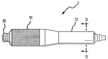
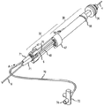
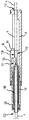
図1は、カテーテル5の可撓性の管状本体4のための制御ハンドル2である本発明の一つの実施形態の等角図である。本明細書を通して、カテーテルという用語は、限定的ではなく、カテーテル、シース及びこれらと類似の医療用装置を含むことを意味している。図1に示されているように、一つの実施形態においては、ハンドル2の末端はカテーテル本体4に結合されており、ハンドル2の基端は電線を含んでおり且つ電気コネクタ8まで延びている。ハンドル2は、隣接するノブ10とハンドルグリップ12とを含んでいる。本明細書から明らかとなるであろうように、本発明のハンドル2は、コンパクトで、ユーザーがハンドル2の長手軸線を中心にハンドルグリップ12を一の方向又は他の方向に枢動させることによって、カテーテル本体の最も末端14を双方向に操作することができるようにするという点で有利である。更に、一つの実施形態においては、ハンドル2は、ハンドル2の基端からカテーテル本体4の最も末端14まで連続して延びている内腔を有している。この内腔は、ガイドワイヤの挿入のためのコントラスト注入のために使用することができる。
FIG. 1 is an isometric view of one embodiment of the present invention that is a
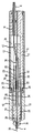
ハンドル2のより詳細な説明のために、図2及び3を参照する。図2は、種々の構成部品を示すために分解されたハンドル2の等角図である。図3は、図1の線AAに沿ったハンドル2の長手断面立面図である。
For a more detailed description of the
図2及び3に示されているように、調整ノブ10は、ハンドルグリップ12内に含まれている取り付けシャフト(すなわち、スライドベース又はベース部分)16に枢動可能に取り付けられている。ノブ10を取り付けシャフト16に枢動可能に取り付けるために、シャフト16の末端のピン穴20内に合わせピン18が挿入され且つノブ10のハブ部分23内の溝22とかみ合っている。ノブ10のハブ部分23とシャフト16の末端との間にシリコーン製のOリング24が配置されている。
As shown in FIGS. 2 and 3, the
図2及び3に示されているように、ワイヤガイド26が、隣接するノブ10内に配置されており且つ止め輪28によって定位置に保持されている。右スライド又は部材30と左スライド又は部材32とが、取り付けシャフト16内の穴(すなわち、スライド室)34内に摺動可能に配置されている。カテーテル本体止めナット36は、カテーテル本体4をワイヤガイド26の末端に固定するために使用されている。
As shown in FIGS. 2 and 3, a
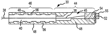
図3に示されているように、一対の撓みワイヤ38が、本体4の最も末端14から、カテーテル本体4、ワイヤガイド26及び2つのスライド30,32間に形成された通路40を通って、スライド30,32の基端部分の近くの場所まで延びている。各ワイヤ38は、次いで、止めねじ42によって個々のスライド30,32に固定される。
As shown in FIG. 3, a pair of
スライド30,32及び撓みワイヤ38に対するこれらのスライドの関係を更に詳細に説明するために、図4を参照する。図4は、右スライド及び左スライド30,32に取り付けられた撓みワイヤ38a,38bの等角図である。図4に示されているように、スライド30,32は、相互に鏡像をなしており、各々、矩形の箱状の基端部分44と半円筒形の末端部分46とを有している。各基端部分44は、概して平らな外側側壁と底壁とを有している。これらの平らな面は、スライド30,32のためのスラスト面として機能する穴34の概して平らな側部及び底部に対して摺動可能に変位する。
To describe the relationship of these slides with respect to the
各半円筒形末端部分46は、長手軸線に沿ってくり抜かれて、撓みワイヤ38a,38b及び図3に示されているように、スライド30,32が組み立てられたハンドル2内にあるときに、撓みワイヤ38a,38b及びワイヤガイド26の狭い基端部分がその中を延びる通路40を形成している。各スライド30,32は平らなスライド面48を有しており、当該スライド面48は、対向する他方のスライド30,32の平らなスライド面48に摺動可能に当接することを意図されている。従って、図2に示されているように、スライド30,32の平らなスライド面48同士が相互に当接し、各スライド30,32の最も基端が互いに同面となったときに、各スライド30,32の半円筒形末端部分46は係合して、その中にチャネル又は通路40を備えた完全なシリンダが形成される。
Each
図4に示されているように、一つの実施形態においては、各撓みワイヤ38a,38bの基端はループ50を形成しており、当該ループ50内を止めねじ42が通ってワイヤ38a,38bを各々のスライド30,32の基端部分に固定している。例示的なスライド30の側面図である図5に示されているように、一つの実施形態においては、各撓みワイヤ38の基端は結節点52を形成している。ワイヤ38は、中空の張力調整ねじ54内を通過し、結節点52はねじ54の頭55に当接し、それによって、ワイヤ38がねじ54の中を引っ張り戻されないようにされている。一つの実施形態においては、ねじの長手軸線及びスライド30,32の長手軸線はほぼ平行である。各張力調整ねじ54は、各々のスライド30,32の基端内にねじ結合によって収容されている。ワイヤ38の張力は、ワイヤ張力調整ねじ54を外方へとねじ回すことによって増大される。従って、ワイヤ38の張力は、ワイヤ張力調整ねじ54を内方へとねじ込むことによって減じられる。
As shown in FIG. 4, in one embodiment, the base end of each
図4から理解できるように、ワイヤ38a,38bが張力を伝達することのみを意図されている一つの実施形態においては、スライド30,32が末端方向に変位したときに、ワイヤ38a,38bは、各スライド30,32の基端部分44内に規定されている開口領域45内で撓み又は曲がることができる。同様に、図5から理解できるように、ワイヤ38が張力を伝達することのみを意図されているもう一つ別の実施形態においては、スライド30,32が末端方向に変位したときに、ワイヤ38は、ねじ54に対して基端方向に摺動することができる。
As can be seen from FIG. 4, in one embodiment where the
図4に示されているように、一つの実施形態においては、右スライド30の半円筒形の末端部分46の外周に右ねじ56が切られており、左スライド32の半円筒形末端部分46の外周に左ねじ58が切られている。他の一つの実施形態においては、右スライド30の半円筒形末端部分46の外周に左ねじが切られており、左スライド32の半円筒形末端部分46の外周には右ねじが切られている。
As shown in FIG. 4, in one embodiment, a right-
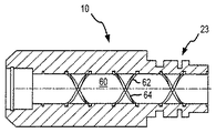
スライドねじ56,58のハンドル2の残りの部分に対する関係をより良く理解するために図6を参照する。図6は、図1の線AAに沿った調整ノブ10の長手断面立面図である。図6に示されているように、円筒形の穴又はシャフト60は、ノブの長手軸線に沿ってノブ10内を貫通している。ノブ10のハブ部分23においては、シャフト60の内周面は、右ねじ62と左ねじ64との両方を有している。ノブ10のこれらの内ねじ62,64は、対応するスライド30,32の外ねじ56,58とかみ合う。より特別には、ノブ10の右ねじ62は右スライド30の外右ねじ56とかみ合い、ノブ10の内左ねじ64は左スライド32の外左ねじ58とかみ合う。
For a better understanding of the relationship of the slide screws 56, 58 to the rest of the
このように、図2,3,4及び6から理解できるように、一つの実施形態においては、ノブ10は、ハンドル2の長手軸線に対して時計方向に回されると、内側及び外側の右ねじ62,56は互いに係合し、内側及び外側の左ねじ64,58も互いに結合し、それによって、ハンドル10内の穴34内での長手方向への右スライド及び左スライド30,32の同時に起こる互いに反対方向の変位が惹き起こされる。特に、ノブ10とスライド30,32とのねじ構造によって、ノブ10がハンドル2のハンドルグリップ12に対して時計方向に回されると、右スライド30は穴34内で末端方向に動き、左スライド32は穴34内で基端方向に動く。これと逆に、ノブ10がハンドル2のハンドルグリップ12に対して反時計方向に回されると、右スライド30は穴34内で基端方向に動き、左スライド32は穴34内で末端方向に動く。
Thus, as can be seen from FIGS. 2, 3, 4 and 6, in one embodiment, the
図4及び6から理解することができるように、右スライド30が末端方向に付勢され左スライド32が基端方向に付勢されるようにノブ10が回されると、右スライド30に結合された撓みワイヤ38aは圧縮状態にされ、左スライド32に結合されている撓みワイヤ38bは伸張状態にされる。このことにより、カテーテル本体4の最も末端14が第1の方向に撓ませられる。逆に、右スライド30が基端方向に付勢され左スライド32が末端方向に付勢されるようにノブ10が回されると、右スライド30に結合された撓みワイヤ38aは伸張状態にされ、左スライド32に結合されている撓みワイヤ38bは圧縮状態にされる。このことにより、カテーテル本体4の最も末端14が第1の方向と反対の第2の方向に撓ませられる。
As can be understood from FIGS. 4 and 6, when the
上記した本発明の制御ハンドル2は幾つかの利点を有している。第一に、ハンドル2はコンパクトで片手で操作することができる。第二に、ねじが切られたスライド30,32とノブ10とが、医師によるカテーテル本体4の末端14の曲がりに対して細かい制御された調整を可能にする。第三に、ひとたびノブ10がカテーテル本体4の末端14に曲がりを生じさせるように回されると、ねじ56,58,62,64は、相互作用して医師側における如何なる作用も必要とすることなく、曲がりを維持する。第四に、スライド30,32は、ハンドル2の長手軸線に沿って末端方向或いは基端方向に単に変位するので、これらは、幾つかの従来技術によるハンドルにおけるワイヤ変位機構と比較して、ワイヤ38を永久的に変形させる傾向がない。第五に、ねじ56,58,62,64は、幾つかの従来技術によるハンドルと比較して、大きな撓みワイヤの移動と医師に対する小さな起動作用とを提供する点において機械的に有利である。
The control handle 2 of the present invention described above has several advantages. First, the
図2乃至6は、スライド30,32が外ねじ56,58を有しており、ノブ10が内ねじ62,64を有している実施形態を示しているけれども、他の実施形態においては、ねじ配列が逆にされている。このような実施形態のうちの一つを説明するために、図33乃至35を参照する。図33は、図1の線AAに沿ったハンドル2の長手断面立面図である。図34は、図33に示されている実施形態において採用されている例示的なスライドの側面図である。図35は、図1の線AAに沿った調整ノブの長手断面立面図である。
2-6 illustrate an embodiment in which the
図33乃至35に示された実施形態を図3,5及び6に示された実施形態と比較することによって、2つの実施形態が、図33乃至35の以下の説明に記載される点以外はほぼ同じであることがわかる。図33乃至35において使用されている参照符号は、図3,5及び6における同じ参照符号によって特定されている同じか又は類似した機構を指している。 By comparing the embodiment shown in FIGS. 33-35 with the embodiment shown in FIGS. 3, 5 and 6, the two embodiments are other than those described in the following description of FIGS. It turns out that it is almost the same. The reference numbers used in FIGS. 33-35 refer to the same or similar features identified by the same reference numbers in FIGS.
図33に示されているように、調整ノブ10は、ハンドルノブ12内に含まれている取り付けシャフト(すなわち、スライドベース又はベース部分)16に枢動可能に取り付けられている。ワイヤガイド26は、調整ノブ10内に配置されている。図2に示されている実施形態のように、図33に図示されている実施形態は、取り付けシャフト16内の穴(すなわち、スライド室)34内に摺動可能に配置されている右スライド又は部材30と左スライド又は部材32とを含んでいる。
As shown in FIG. 33, the
図34から理解できるように、相対的に鏡像をなしているスライド30,32は、各々、矩形の箱状基端部分44と矩形又は半円筒形とすることができる末端部分46とを有している。各基端部分44は、ほぼ平らな外側壁と側壁とを有している。これらの平らな面は、穴34の概して平らな側部及び底部に向けて変位し、側部30,32のためのスラスト面として機能する。
As can be seen from FIG. 34, the relatively mirrored slides 30, 32 each have a rectangular box-shaped
末端部分46の各々は、くり抜かれていて、スライド30,32が側部体側部の関係で相対的に当接せしめられて形成される円筒形通路40の半分を形成している。このようにして、各スライド30,32の各々の末端部分46は、円周面を含んでおり、この円周面は、他方のスライド30,32の内周面と組み合わせられて円筒形通路40を規定している。
Each of the
図34に示されているように、一つの実施形態においては、右スライド30の内周面は、右ねじ56と螺合している。同様に、図34から理解できるように、左スライド32の内周面は、左ねじ58と螺合している。各スライド30,32の末端部分46に内ねじが備えられている。もう一つ別の実施形態においては、右スライド30の内周面は、左ねじ58と螺合している。同様に、左スライド32の内周面は右ねじ56と螺合している。
As shown in FIG. 34, in one embodiment, the inner peripheral surface of the
図35に示されているように、ノブ10は、内側ハブ23bを取り巻いている外側ハブ23aを含んでいる。内側ハブ23aと外側ハブ23bとの間には隙間65が存在し且つ形成されている。隙間65は、各スライド30,32の末端46を収容するようになされている。内側ハブ23bの外周面は、右ねじ62と左ねじ64とを有している。ノブ10のこれらの外ねじ62,64は、スライド30,32の対応する内ねじ56,58とかみ合う。より特定すると、ノブ10の外右ねじ62は右スライド30の内右ねじ56とかみ合い、ノブ10の外左ねじ64は左スライド32の内左ねじ58とかみ合う。
As shown in FIG. 35, the
図33から理解できるように、一つの実施形態においては、ノブ10がハンドル2の長手軸線に対して時計方向に回転せしめられると内右ねじと外右ねじ56,62とが係合し、内左ねじと外左ねじ58,64とが係合し、それによって、ハンドル10の穴34内で長手方向に右スライドと左スライド30,32の同時に起こる反対方向の変位が惹き起こされる。特に、ノブ10とスライド30,32とのねじ構造により、ノブ10がハンドル2のハンドルグリップ12に対して時計方向に回転されると、右スライド30は穴34内を末端方向へ動き、左スライド32は穴34内を基端方向へ動く。逆に、ノブ10がハンドル2のハンドルグリップ12に対して反時計方向に回されると、右スライド30は穴34内を基端方向に動き、左スライド32は穴34内を末端方向へ動く。
As can be seen from FIG. 33, in one embodiment, when the
図33から理解できるように、右スライド30が末端方向へ付勢され、左スライド32が基端方向へ付勢されるようにノブ10が回されると、右スライド30に結合されている撓みワイヤ38が圧縮状態とされ、左スライド32に結合されている撓みワイヤ38は伸張状態とされる。これによって、カテーテル本体4の最も末端14が第1の方向へ撓ませられる。逆に、右スライド30が基端方向に付勢され、左スライド32が末端方向へ付勢されるように回されると、右スライド30に結合されている撓みワイヤ38は伸張状態とされ、左スライド32に結合されている撓みワイヤ38は圧縮状態とされる。これによって、カテーテル本体4の最も末端14が、前記第1の方向と反対の第2の方向へ撓ませられる。
As can be seen from FIG. 33, when the
本発明のハンドル2の別の実施形態を詳細に説明するために、図7,8及び9を参照する。図7はハンドル2の平面図であり、図8はハンドル2の側面図である。図9はハンドル2の末端の等角図である。
To describe another embodiment of the
図7乃至9に示されているように、ハンドル2は、末端に調整ノブ10を含んでおり、基端にハンドルグリップ12を含んでいる。図7乃至9から理解できるように、一つの実施形態においては、ノブ10はほぼ円形断面を有しており、ハンドルグリップ12はほぼ楕円形断面を有している。一つの実施形態においては、ノブ10とハンドルグリップ12との両方がほぼ円形断面を有している。ハンドルグリップ12の楕円形断面は、カテーテルの回転位置の触覚による指示を医師に付与するので有利である。
As shown in FIGS. 7-9, the
ハンドル2の構成部品をより詳細に説明するために図10を参照する。図10は、図9の線BBに沿ったハンドル2の長手断面立面図である。図10に示されているように、ハンドルグリップ12とノブ10の溝との間にOリング24が配置されている。ノブ10は、ノブとハンドルグリップ12との両方の溝内に位置する回転止めリング60によってハンドルグリップ12に枢動可能に固定されている。
To describe the components of the
図10に示されているように、カテーテル本体止めナット36は、ノブ10の中心軸線に沿って延びているワイヤガイド26の末端に螺結されている。図10に示されており且つ図9の線BBに沿った長手断面平面図である図11により明確に示されているように、円筒形の穴又はシャフト60は、長手軸線に沿ってノブ10の中を貫通している。シャフト60の円周面は、ノブ10のハブ部分23からノブ10の末端に向かって延びている右ねじ62と左ねじ64との両方を備えている。図11に示されているように、一つの実施形態においては、ノブ10は単一の一体部品である。
As shown in FIG. 10, the catheter
図10に示されているように、右スライド30及び左スライド32は、ハンドル2内で長手方向に且つワイヤガイド26の基端を中心に変位可能である。各々、ワイヤガイド26を中心に変位されたスライド30,32の右側等角図及びワイヤガイド26を中心に変位せしめられたスライド30,32の左側等角図である図12及び13に示されているように、各スライド30,32は、対向するスライド30,32の側面48に当接し且つこれに対して変位可能である平らな側面48を有している。更に、各スライド30,32は、対向するスライド30,32のチャネル40と結合して、スライド30,32がワイヤガイド26を中心に変位したときにワイヤガイド26の基端が通過する通路を形成するチャネル40を備えている。図10に示されているように、チャネル40によって形成された通路はまた、撓みワイヤ38a,38b(図10において点線によって示されている)がスライド30,32の基端から、ワイヤガイド26内を通ってカテーテル本体4の最も末端14まで移動する経路をも提供する。
As shown in FIG. 10, the
図12及び13に示されているように、各スライド30,32は、半円筒形の末端部分46と、より短く且つより幅が広い半円筒形の基端部分47とを備えている。右スライド30は、その末端部分46上に右ねじ56を備えている。同様に、左スライド32はその末端46に左ねじを有している。従って、図10から理解できるように、ノブ10がハンドルグリップ12に対して時計方向に回転されると、ノブ10内の右ねじ62は、右スライド30の右ねじ56と係合し、ノブ10内の左ねじ64は左スライド32の左ねじ58と係合する。この結果、右スライド30はハンドル2内で末端方向に変位せしめられ、左スライド32はハンドル2内で基端方向に変位せしめられる。従って、右スライド30に取り付けられている撓みワイヤ38aは、押され(すなわち、圧縮力を受け)、左スライド32に取り付けられている撓みワイヤ38bは引っ張られる(すなわち、引っ張り力を受ける)。逆に、ノブが反時計方向に回される場合には、スライド30,32及び撓みワイヤ38a,38bの反対の変位が生じるであろう。
As shown in FIGS. 12 and 13, each
図10に示されているように、各撓みワイヤ38a,38bは、止めねじ42によって、各々のスライド30,32の基端部分47に取り付けらている。図12及び13により明確に示されている止めねじは、基端部分47内にねじ結合によって取り付けられている。
As shown in FIG. 10, each bending
図12及び13に示されているように、スライド30,32の各半円筒形の基端部分47は、それら各々の平らなスライド面48に隣接して上方及び下方の平らな切り込み64を有している。これらの切り込み64の機能は、図14及び15を参照することによって理解できる。
As shown in FIGS. 12 and 13, each semi-cylindrical
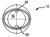
図14は、図7の線CCに沿ったハンドルグリップ12の長手断面立面図である。図15は、図8の線DDに沿ったハンドルグリップ12の横断面立面図である。図14及び15に示されているように、ハンドルグリップ12は、図10に示されているように、スライド30,32の基端部分47がその内部で変位することができる内側円筒形空洞66を有している一体部品である。
14 is a longitudinal sectional elevation view of the
図14及び15に示されているように、上方及び下方のリブ68は、内側円筒形空洞66を形成している壁から延びている。リブ68は、円筒形空洞の長さの実質的な部分に沿って長手方向に延びている。図12乃至15から理解できるように、スライド30,32の基端部分47上の上方の平らな切り込み64は、円筒形空洞66内でスライド30,32が変位するときに、上方リブ68とかみ合い且つ当該上方リブに沿って変位する。同様に、スライド30,32の基端部分47上の下方の平らな切り込み64は、円筒形空洞66内でスライド30,32が変位するときに、下方リブ68とかみ合い且つ当該下方リブに沿って変位する。このように、リブ68は、スライド30,32のためのスラスト面として機能する。
As shown in FIGS. 14 and 15, the upper and
図7乃至15に示されたハンドル2のもう一つ別の実施形態の詳細な説明のために図16を参照する。図16は、ハンドル2及びカテーテル本体4が貫通内腔70を有しているカテーテル5のための制御ハンドル2の末端の等角図である。図16に示されているように、一つの実施形態においては、内腔70と、電気コネクタ8へと延びている電線チューブ6とは、歪み解放部71内を通り、ハンドルグリップ12の基端内へと延びている。一つの実施形態においては、止め栓72をガイドワイヤ挿入のために利用することができる。図16に示されているように、内腔70の長い可撓性の長さは、注射器とは対照的に、挿入中の動きの隔離を提供するけれども、内腔70はハンドルグリップ12から延びていない。その代わりに、止め栓72又はルアー嵌合部は、単に内腔70に取り付けられており、当該内腔70においてハンドルグリップ12の基端を出て行っている。
Reference is made to FIG. 16 for a detailed description of another embodiment of the
内腔70の経路をより良く理解するために、図17,18及び19を参照する。図17は、スライド30,32、ワイヤガイド26、電線チューブ6及びハンドル2内で内腔70が採る経路を示している内腔70の等角図である。図18は、図17において矢印Aの方向から見たスライド30,32の最も基端面の正面図であり、内腔70及び電線チューブ6がスライド30,32のチャネル40によって形成された通路内へ入る経路を示している。図19は、内腔70、撓みワイヤ38a,38b及びハンドル2の末端においてカテーテル本体止めナット36を出て行く電線チューブ6の電線76の等角図である。
For a better understanding of the
図17及び18に示されているように、内腔70及び電線チューブ6は、それらの各々の歪み解放部71内を通過し且つ各スライド30,32内のチャネル40によって形成されている通路40へと延びている。一つの実施形態においては、電線チューブ6及び内腔70が通路40へ入るとすぐに、電線チューブ6のワイヤ76は、電線チューブ6を出て行き且つ図19に示されているように内腔70の外周の周りに分散せしめられる。
As shown in FIGS. 17 and 18, the
図17に示されているように、別の実施形態においては、電線チューブ6及び内腔70が通路40内へ入った後に、電線チューブ6及び内腔70は、側部対側部の構造でスライド30,32内に形成された通路40内を通過することによって、カテーテル本体4の末端14までそれらの経路をたどり、ワイヤガイド26の長手軸線に沿って延びている内側通路内へと続いている。ワイヤガイド26の端部近くで、ワイヤ76は電線チューブ6を出て行く。ワイヤ76、内腔70及び撓みワイヤ38a,38bは、次いで、図19に示されているように、ハンドルのカテーテル本体止めナット36を出て行くことによって、カテーテル内へと入る。
In another embodiment, as shown in FIG. 17, after the
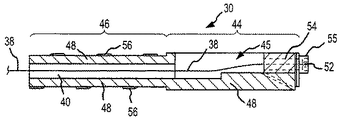
ハンドル2の別の実施形態を詳細に説明するために、図20を参照する。図20は、ハンドル2の種々の構成部品を示すために分解されているハンドル2の等角図である。図20から理解できるように、図20に示されたハンドル2の機構は、図2に示されたハンドルの機構と類似しており、図20に示されたハンドル2は比較的大きく、直径がほぼ均一で、経路がハンドル2の全長(すなわち、ワイヤガイド26内の末端開口部102から、側部30,32に形成された通路40を通り、シャフト16の基端の出口穴104まで)に亘っている点で異なっている。
To describe another embodiment of the
図20に示されているように、比較的大きな概して均一な直径の経路がハンドル2の全長を通過するのを可能にするハンドル2の構造が図21により明確に示されている。図21は、図20の線ZZに沿った長手断面立面図である。図21に図示されているように、一つの実施形態においては、ガイド26内を通る通路及びスライド30,32を通る通路40を含んでいる経路100は、カテーテル本体4自体が経路100内を通過し且つ出口穴104においてシャフト16の基端に結合されるのに十分な大きさである。従って、一つの実施形態においては、カテーテル本体4が調整ノブ10と共に回転するのを阻止するために、カテーテル本体4は出口穴104においてシャフト16に固定されている。一つの実施形態においては、カテーテル本体4は、図21に示されているようにハンドル4の全長に亘って延びているが、本体4は末端開口部102において又はその近くでワイヤガイド26に固定されている。一つの実施形態においては、カテーテル本体4は、末端開口部102における又はその近くのガイドワイヤ26及び出口穴104のシャフト16の両方に固定されている。
As shown in FIG. 20, the structure of the
図21から理解できるように、通路40の部分及びそれらの平らな側面48を示す方向に向けられたスライド30,32の等角図である図22においてより明確に示されているように、通路40は、ワイヤガイド26の外径の外周に沿って変位するのに十分な大きさの直径を有している。図21及び22に示されているように、カテーテル本体の通路110は、各スライド30,32の基端部分44内を通過しており、それによって、スライド30,32がカテーテル本体4の外面上を前後に動くことができるようにされている。
As can be seen from FIG. 21, the passages, as shown more clearly in FIG. 22, which is an isometric view of the
図21に示されているように、一つの実施形態においては、カテーテル本体4は、その壁に開口部111を有しており、この開口部は、ワイヤ38が本体4を出て行き且つスライド30,32に結合するのを可能にしている。一つの実施形態においては、ワイヤ38は、既に説明したように、張力調整ねじ54によってスライド30,32に結合されている。
As shown in FIG. 21, in one embodiment, the
スライド30,32、ワイヤガイド及びシャフト16の構造によって、カテーテル本体4は、ハンドル2の全長に亘って連続して延びることができる。この結果、電線76(図19参照)と内腔70とは、本体4を経由してハンドル2の全長を回送することができる。
Due to the structure of the
本発明のハンドル2の別の実施形態を詳細に説明するために、図23及び24を参照する。図23は、ハンドル2の種々の構成部品を示すように分解されたハンドル2の等角図である。図24は、図23の線YYに沿ったハンドル2の長手断面立面図である。一般的に言うと、図23及び24に示されているハンドル2の機構は、図20に示されているハンドルの機構と類似しており、2つの実施形態は異なるスライダ構造を採用している点のみが異なっている。例えば、図1乃至22に示された実施形態は、平行なスライド又は部材30,32(すなわち、スライド30,32は、平行又は側部対側部の配列でハンドル2内に位置している)を採用している。図23及び24及びそれに続く図面から理解されるように、図23及び24に示されているハンドル2においては、スライド又は部材150,152は、直列配置で(すなわち、スライド150,152は、互いに平行又は側部体側部の配置ではなく、ハンドル2の長手軸線に沿って端部対端部の配置で配向されている)調整ノブ10内に配置されている。
To describe another embodiment of the
図23及び24に示されているように、調整ノブ10は、取り付けシャフト(すなわち、ベース部分)16の末端に枢動可能に結合されている。ワイヤガイド26は、調整ノブ10及び取り付けシャフト16の中心を貫通している。カテーテル本体4は、ワイヤガイド26の末端に結合されており、一つの実施形態においては、ワイヤガイド26内を貫通し且つ取り付けシャフト16の基端から出て行っている。
As shown in FIGS. 23 and 24, the
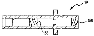
図23及び24に示されているように、末端のスライド150は調整ノブ10の末端部分内に配置されており、基端のスライド152は調整ノブ10の基端部分(すなわち、ハブ部分23)内に配置されている。図24に示されているように、各スライド150,152の外面は、調整ノブ10の内面上のねじ156とかみ合うねじ154を有している。
As shown in FIGS. 23 and 24, the
図24に示されているように、各撓みワイヤ38a,38bは、ワイヤガイド26の側壁内の穴157においてワイヤガイド26を出て行くまで、ワイヤガイド26の内部に沿って延びている。各撓みワイヤ38a,38bは、次いで、撓みワイヤ38a,38bが取り付けられているスライド150,152まで延びている。一つの実施形態においては、スライド150,152に取り付けるために、撓みワイヤ38a,38bは、スライド150,152内の通路159内を通り、この詳細な説明において既に説明したように、結節点52によって中空の張力調整ねじ54に取り付けられている。
As shown in FIG. 24, each
ねじ154,156の向きをより良く理解できるように、図25及び26を参照する。図25は、調整ノブ10自体が示されていること以外は、図24において示されたものと同じ調整ノブ10の長手断面立面図である。図26はスライド150,152の側面図である。
To better understand the orientation of the
図25及び26に示されているように、一つの実施形態においては、末端のスライド150は調整ノブ10の末端部分内の右ねじ156と係合する右ねじ154を有しており、基端スライド152は、調整ねじ10の基端部分内の左ねじ156と係合する左ねじ154を有している。従って、図23乃至26から理解できるように、調整ノブ10がハンドル2の長手軸線を中心に第1の方向へ取り付けシャフト16に対して回転せしめられて、スライド150,152は、ワイヤガイド26に沿って収束し、それによって、第1のワイヤ38が伸張状態に配置され、第2のワイヤ38が圧縮されるようにするであろう。この結果、カテーテル本体4の末端14は第1の方向に撓むであろう。同様に、調整ノブ10が前記第1の方向と反対の第2の方向に回転せしめられると、スライド150,152は、ワイヤガイド26に沿って分かれ、それによって、第1のワイヤ38を圧縮せしめ第2のワイヤ38を伸張状態にするであろう。この結果、カテーテル本体4の末端は、第1の方向とほぼ反対の第2の方向に撓むであろう。
As shown in FIGS. 25 and 26, in one embodiment, the
一つの実施形態においては、調整ノブ10が回されたときにスライド150,152が簡単にワイヤガイド26を中心に回転しないようにするために、スライド150,152及びワイヤガイド26は、スライド150,152がワイヤガイド26に沿って変位するが当該ガイドワイヤを中心に回転せしめられないような構造とされている。例えば、図24の線XXに沿ったハンドル2の横断面立面図である図27Aに示されているように、ワイヤガイド26は、スライド150,152の全長に亘って延びている正方形の穴162とかみ合う正方形断面を有している。正方形の穴162とワイヤガイド26の正方形断面との間の相互作用によって、スライド150,152がワイヤガイド26を中心に回転するのを阻止するが、依然として、スライド150,152がワイヤガイド26の長さに沿って変位せしめられる。
In one embodiment, the
別の実施形態においては、図27Aに示されているものと同じ横断面立面図である図27Bに示されているように、各スライド150,152は、円形断面を有する穴162を有している各穴162は、各々のスライド150,152の全長に亘って延びており且つ穴160の内周面から穴162内へと延びているキー160を含んでいる。キー160は、ワイヤガイド26の一つの実施形態の側面図である図28に示されているように、ワイヤガイド26の全長に沿って延びている溝又はスロット158と係合している。キー160とスロット158との間の相互作用によって、スライド150,152がワイヤガイド26を中心に回転するのが阻止されるが、依然として、スライド150,152はワイヤガイド26の長さに沿って変位せしめられる。
In another embodiment, as shown in FIG. 27B, which is the same cross-sectional elevation view as shown in FIG. 27A, each
図27A及び27Bに示されているように、中空のシャフト165は、ワイヤガイド26内を伸長している。これによって、内腔を備えたカテーテル本体4が図24に示されているようにハンドル2内を完全に伸長するのが可能になる。
As shown in FIGS. 27A and 27B, a
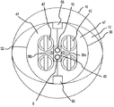
図23に示された実施形態と類似しているハンドル2の別の実施形態を詳細に説明するために、図29及び30を参照する。図29は、図23の線YYに沿ったハンドル2の長手断面立面図である。図30は、図23の線VVに沿ったハンドル2の長手断面平面図であり、線VVは、図23における線YYによって形成された面に直角な面を形成している。
To describe in detail another embodiment of the
図29及び30に示されているように、ハンドル2は、取り付けシャフト(すなわち、ベース部分)16の末端に枢動可能に結合された調整ノブ10を含んでいる。一つの実施形態においては、調整ノブ10は、基端170、末端172及び基端170に結合されており且つ調整ノブ10の長手軸線に沿って末端方向に延びているねじが切られたシャフト173を含んでいる。ねじが切られたシャフト173は、末端174、基端176、シャフト173の末端部分に沿った一連の右ねじ178及びシャフト173の基端部分に沿った一連の左ねじ180を含んでいる。
As shown in FIGS. 29 and 30, the
図29及び30に示されているように、末端のスライド150は調整ノブ10の末端部分に配置されており、基端のスライド152は調整ノブ10の基端部分(すなわち、ハブ部分23)内に配置されている。各スライドは、ねじが切られたシャフト173が貫通する穴155を備えている。末端のスライド150のための穴155の内周面は、シャフト173の末端部分の右ねじ178とかみ合う右ねじを有している。同様に、基端のスライド152の穴155の内周面は、シャフト173の基端部分の左ねじ180とかみ合う左ねじを有している。他の実施形態においては、左ねじ及び右ねじのための位置は逆にされている。
29 and 30, the
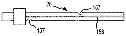
ワイヤガイド26の一つの実施形態の等角図である図29,30及び31から理解できるように、中空の中心シャフト182は、ワイヤガイド26の末端から、調整ノブ10のねじが切られたシャフト173内を通り、ベースシャフト16の基端へと延びている。従って、一つの実施形態においては、カテーテル本体4は、ワイヤガイドの中空の中心シャフト182の内腔内を回送されて、図29及び30に示されているように、ハンドル2の基端を出て行くことができる。
As can be seen from FIGS. 29, 30 and 31, which are isometric views of one embodiment of the
図29に示されているように、各撓みワイヤ38a,38bは、ワイヤガイド26の側壁の穴157においてワイヤガイド26を出て行くまで、ワイヤガイド26の内部に沿って延びている。各撓みワイヤ38a,38bは、次いで、撓みワイヤ38a,38bが取り付けられているスライド150,152まで延びている。一つの実施形態においては、スライド150,152に取り付けるために、撓みワイヤ38a,38bは、スライド150,152内の通路159を貫通し、本明細書において既に説明したように、結節点52によって中空の張力調整ねじ54に取り付けられている。
As shown in FIG. 29, each
一つの実施形態においては、図29に示されているように、基端のスライド152に続いている撓みワイヤ38bは、末端のスライド150内の第2の通路161内を貫通している。第2の通路161は、末端のスライド150が末端方向及び基端方向に変位するときに通路161がワイヤ38bに沿って容易に変位するのに十分な隙間を有している。第2の通路161は、ワイヤ38bを堅牢にし且つワイヤ38bが圧縮されたときに曲がる傾向を減じる助けとなるガイドとして機能する。
In one embodiment, as shown in FIG. 29, the
図29及び30から理解できるように、調整ノブ10がハンドル2の長手軸線を中心に第1の方向へ取り付けシャフト173に沿って収束し、それによって、第1のワイヤ38aが伸張状態にされ、第2のワイヤ38bが圧縮されるようにするであろう。この結果、カテーテル本体4の末端14は第1の方向に撓むであろう。同様に、調整ノブ10が第1の方向と反対の第2の方向に回転されると、スライド150,152は、ねじが切られたシャフト173に沿って分岐し、それによって、第1のワイヤ38aが圧縮され、第2のワイヤ38bが伸張状態にされるようにするであろう。この結果、カテーテル本体4の末端14は、第1の方向とほぼ反対の第2の方向に撓むであろう。
29 and 30, the
一つの実施形態においては、調整ノブ10が回されると、スライド150,152が調整ノブ10内のねじが切られたシャフト173と共に簡単に回転するのを阻止するために、スライド150,152とワイヤガイド26とは、スライド150,152がねじが切られたシャフト73に沿って変位するが、調整ノブ10内で回転しないような構造とされている。図29の線WWに沿ったハンドル2の横断面立面図である図31及び32に示されているように、ワイヤガイド26は、相互に反対で且つワイヤガイド26の中空シャフト182の長さに沿って延びている右及び左の半円形部分190を有している。図32に示されているように、半円形部分190のほぼ平らな対向面192は、スライド150,152の概して平らな側面194に当接している。この相互作用によって、ノブ10が回転せしめられたときに、スライド150,152が調整ノブ10内で回転するのが阻止されるが、依然として、ねじが切られたシャフト173の長さに沿ってスライド150,152が変位せしめられる。
In one embodiment, when the
患者200に対する外科的処置において採用されている本発明の制御ハンドル2の概略図である図36から理解できるように、カテーテル本体4の末端14は、(例えば、患者200の体腔202を介して脈管へ、又は経皮的に、又は管状の体内に入る他の手段を介して)管状200の体内に挿入される。カテーテル本体4の末端14は、患者200の体内(例えば、患者の心臓206又はその他の器官のチャンバ内、患者の体腔内等)の選択された位置に位置決めされるまで進入せしめられる。カテーテル本体4の末端は、次いで、ベース部分16の長手軸線を中心に調整ノブ10を回転させることによって撓ませられる。図1乃至25から理解できるように、これによって、ハンドル2内のスライド30,32が長手軸線に沿って反対方向に変異せしめられる。各スライド30,32はそれら自体の撓みワイヤ38に結合されており、各撓みワイヤ38はカテーテル本体4内を延び且つ末端14に結合されているので、カテーテル本体4の末端14は撓ませられる。
As can be seen from FIG. 36 which is a schematic view of the control handle 2 of the present invention employed in a surgical procedure on a
以上、本発明を好ましい実施形態に関して説明したけれども、当業者は、本発明の精神及び範囲から逸脱することなく、形態及び細部に変形を施すことができることを認識できるであろう。 Although the present invention has been described with reference to preferred embodiments, workers skilled in the art will recognize that changes may be made in form and detail without departing from the spirit and scope of the invention.
Claims (14)
スライドベースであって、第1の端部、第2の端部及び当該スライドベースの少なくとも一部分内を長手方向に延びているスライド室とを含んでいるスライドベースと、
前記スライドベースの前記第1の端部に回転可能に結合された調整ノブであって、当該調整ノブ内に穴が延びており、当該穴の内径の少なくとも一部分が内側右ねじと内側左ねじとを含んでいる前記調整ノブと、
前記スライド室内に配置されており且つ前記第1の撓みワイヤに結合されるようになされており且つ外側右ねじを含んでいる第1のスライドと、
前記スライド室内に配置されており且つ前記第2の撓みワイヤに結合されるようになされており且つ外側左ねじを含んでいる第2のスライドと、を含んでおり、
前記調整ノブの内側ねじが、前記スライドの外側ねじと係合し、前記調整ノブの回転によって前記スライドが前記スライド室内で互いに反対方向に変位せしめられるようになされたハンドル。 A handle for controlling the deflection of the distal end of the catheter body including first and second deflection wires comprising:
A slide base including a first end, a second end, and a slide chamber extending longitudinally within at least a portion of the slide base;
An adjustment knob rotatably coupled to the first end of the slide base, wherein a hole extends into the adjustment knob, and at least a part of the inner diameter of the hole includes an inner right screw and an inner left screw. The adjustment knob including:
A first slide disposed within the slide chamber and adapted to be coupled to the first flexure wire and including an outer right-hand thread;
A second slide disposed within the slide chamber and adapted to be coupled to the second deflection wire and including an outer left-hand thread;
A handle in which an inner screw of the adjustment knob engages with an outer screw of the slide, and the rotation of the adjustment knob causes the slide to be displaced in opposite directions within the slide chamber.
ハンドルカバーを更に含んでおり、前記スライドベースが当該ハンドル内に収納され、前記スライド室が前記カバーによって包囲されているハンドル。 The handle according to claim 1,
A handle further comprising a handle cover, wherein the slide base is housed in the handle and the slide chamber is surrounded by the cover.
ワイヤガイドを更に含んでおり、当該ワイヤガイドの少なくとも一部分が前記調整ノブの穴内に位置されており、前記第1及び第2の撓みワイヤが前記ワイヤガイド内を貫通しているハンドル。 The handle according to claim 1,
A handle further comprising a wire guide, wherein at least a portion of the wire guide is positioned within the hole of the adjustment knob, and wherein the first and second flexure wires pass through the wire guide.
前記第1及び第2のスライドの一部分が前記ワイヤガイドの外面に沿って変位するようになされたハンドル。 The handle according to claim 3,
A handle adapted to displace a portion of the first and second slides along an outer surface of the wire guide.
前記ワイヤガイドの端部が前記カテーテル本体に結合されているハンドル。 The handle according to claim 4, wherein
A handle in which an end of the wire guide is coupled to the catheter body.
前記スライドベースの第1の端部が末端であり、前記スライドの第2の端部が基端であるハンドル。 The handle according to claim 4, wherein
A handle in which a first end of the slide base is a distal end and a second end of the slide is a proximal end.
前記カテーテル本体の基端が前記ワイヤガイドの末端に結合されているハンドル。 The handle according to claim 6, wherein
A handle having a proximal end of the catheter body coupled to a distal end of the wire guide.
前記第1及び第2のスライドの一部分が前記カテーテル本体の外面に沿って変位するハンドル。 The handle according to claim 1,
A handle in which portions of the first and second slides are displaced along the outer surface of the catheter body.
前記カテーテル本体の基端が当該ハンドルの基端に結合されているハンドル。 The handle according to claim 8, wherein
A handle having a proximal end of the catheter body coupled to a proximal end of the handle.
前記スライドの内面と前記カテーテル本体の外面との間に配置されているワイヤガイドを更に含んでいるハンドル。 The handle according to claim 8, wherein
A handle further comprising a wire guide disposed between an inner surface of the slide and an outer surface of the catheter body.
前記第1のスライドが前記スライドのフレームと接触している第1の接触点を形成しており、前記第2のスライドが前記スライドのフレームと接触している第2の接触点を形成しており、これらの接触点は、前記調整ノブが回転せしめられたときに前記スライド室内で前記スライドが回転可能に変位するのを防止する機能を果たすハンドル。 The handle according to claim 1,
The first slide forms a first contact point in contact with the slide frame, and the second slide forms a second contact point in contact with the slide frame. These contact points are handles that serve to prevent the slide from being rotatably displaced in the slide chamber when the adjustment knob is rotated.
前記第1の接触点が、スライドフレームの第1の側と、前記第1のスライドと第2のスライドとの間に形成された溝の第1の半体との間に位置しており、前記第2の接触点が、レールの第2の側面と前記溝の第2の半体との間に位置しているハンドル。 The handle according to claim 11, wherein
The first contact point is located between a first side of a slide frame and a first half of a groove formed between the first slide and the second slide; A handle in which the second contact point is located between a second side of the rail and a second half of the groove.
前記第1の接触点が、前記スライド室の第1の平らな面と、前記第1のスライドの平らな面との間に位置しており、前記第2の接触点が、前記スライド室の第2の平らな面と前記第2のスライドの平らな面との間に位置しているハンドル。 The handle according to claim 11, wherein
The first contact point is located between the first flat surface of the slide chamber and the flat surface of the first slide, and the second contact point is located on the slide chamber. A handle positioned between a second flat surface and the flat surface of the second slide.
各スライドが長手軸線を有するボルトを含み且つ当該ボルトを螺合状態で収容し、各スライドの各々の撓みワイヤが各々のボルトの長手軸線内を貫通しているハンドル。 The handle according to claim 1,
A handle in which each slide includes a bolt having a longitudinal axis and accommodates the bolt in a threaded manner, and each deflection wire of each slide passes through the longitudinal axis of each bolt.
Applications Claiming Priority (1)
| Application Number | Priority Date | Filing Date | Title |
|---|---|---|---|
| US11/023,667 US7691095B2 (en) | 2004-12-28 | 2004-12-28 | Bi-directional steerable catheter control handle |
Publications (2)
| Publication Number | Publication Date |
|---|---|
| JP2006187606A JP2006187606A (en) | 2006-07-20 |
| JP4468296B2 true JP4468296B2 (en) | 2010-05-26 |
Family
ID=35840242
Family Applications (1)
| Application Number | Title | Priority Date | Filing Date |
|---|---|---|---|
| JP2005369070A Active JP4468296B2 (en) | 2004-12-28 | 2005-12-22 | Bidirectionally pushable catheter control handle |
Country Status (7)
| Country | Link |
|---|---|
| US (5) | US7691095B2 (en) |
| EP (1) | EP1676595B1 (en) |
| JP (1) | JP4468296B2 (en) |
| AT (1) | ATE409062T1 (en) |
| CA (2) | CA2648336C (en) |
| DE (1) | DE602005009916D1 (en) |
| ES (1) | ES2309645T3 (en) |
Cited By (1)
| Publication number | Priority date | Publication date | Assignee | Title |
|---|---|---|---|---|
| WO2022085761A1 (en) | 2020-10-22 | 2022-04-28 | 東郷メディキット株式会社 | Medical device |
Families Citing this family (341)
| Publication number | Priority date | Publication date | Assignee | Title |
|---|---|---|---|---|
| US10835307B2 (en) | 2001-06-12 | 2020-11-17 | Ethicon Llc | Modular battery powered handheld surgical instrument containing elongated multi-layered shaft |
| US8182501B2 (en) | 2004-02-27 | 2012-05-22 | Ethicon Endo-Surgery, Inc. | Ultrasonic surgical shears and method for sealing a blood vessel using same |
| AU2005295010B2 (en) | 2004-10-08 | 2012-05-31 | Ethicon Endo-Surgery, Inc. | Ultrasonic surgical instrument |
| US8858495B2 (en) * | 2004-12-28 | 2014-10-14 | St. Jude Medical, Atrial Fibrillation Division, Inc. | Five degree of freedom ultrasound catheter and catheter control handle |
| US7691095B2 (en) | 2004-12-28 | 2010-04-06 | St. Jude Medical, Atrial Fibrillation Division, Inc. | Bi-directional steerable catheter control handle |
| US8608797B2 (en) | 2005-03-17 | 2013-12-17 | Valtech Cardio Ltd. | Mitral valve treatment techniques |
| US20070191713A1 (en) | 2005-10-14 | 2007-08-16 | Eichmann Stephen E | Ultrasonic device for cutting and coagulating |
| US8083879B2 (en) * | 2005-11-23 | 2011-12-27 | Intuitive Surgical Operations, Inc. | Non-metallic, multi-strand control cable for steerable instruments |
| US8066664B2 (en) * | 2005-12-12 | 2011-11-29 | Taheri Laduca Llc | Tri-directional articulating catheter |
| US7621930B2 (en) | 2006-01-20 | 2009-11-24 | Ethicon Endo-Surgery, Inc. | Ultrasound medical instrument having a medical ultrasonic blade |
| US9642982B2 (en) * | 2006-05-05 | 2017-05-09 | Cathrx Ltd. | Modular catheter assembly |
| WO2007136754A2 (en) | 2006-05-19 | 2007-11-29 | Boston Scientific Limited | Control mechanism for steerable medical device |
| CA2659776A1 (en) * | 2006-08-04 | 2008-02-07 | Cathrx Ltd | A catheter handle assembly |
| CA2878598C (en) * | 2006-09-08 | 2018-05-01 | Edwards Lifesciences Corporation | Integrated heart valve delivery system |
| WO2008049088A2 (en) | 2006-10-21 | 2008-04-24 | Rollins Aaron M D | Guidewire manipulation device |
| JP4706008B2 (en) * | 2006-10-26 | 2011-06-22 | 有限会社リバー精工 | Cardiac catheter |
| US11259924B2 (en) | 2006-12-05 | 2022-03-01 | Valtech Cardio Ltd. | Implantation of repair devices in the heart |
| US9974653B2 (en) | 2006-12-05 | 2018-05-22 | Valtech Cardio, Ltd. | Implantation of repair devices in the heart |
| US9114229B2 (en) | 2006-12-29 | 2015-08-25 | St. Jude Medical, Af Division, Inc. | Dual braid reinforcement deflectable device |
| US9950141B2 (en) | 2006-12-29 | 2018-04-24 | St. Jude Medical, Atrial Fibrillation Division, Inc. | Dual braid reinforcement deflectable device (sheath or catheter) |
| CA2677343C (en) | 2007-02-05 | 2016-06-21 | Boston Scientific Limited | Thrombectomy apparatus and method |
| US11660190B2 (en) | 2007-03-13 | 2023-05-30 | Edwards Lifesciences Corporation | Tissue anchors, systems and methods, and devices |
| US8911460B2 (en) | 2007-03-22 | 2014-12-16 | Ethicon Endo-Surgery, Inc. | Ultrasonic surgical instruments |
| US8142461B2 (en) | 2007-03-22 | 2012-03-27 | Ethicon Endo-Surgery, Inc. | Surgical instruments |
| US8057498B2 (en) | 2007-11-30 | 2011-11-15 | Ethicon Endo-Surgery, Inc. | Ultrasonic surgical instrument blades |
| US8523889B2 (en) | 2007-07-27 | 2013-09-03 | Ethicon Endo-Surgery, Inc. | Ultrasonic end effectors with increased active length |
| US8808319B2 (en) | 2007-07-27 | 2014-08-19 | Ethicon Endo-Surgery, Inc. | Surgical instruments |
| US9044261B2 (en) | 2007-07-31 | 2015-06-02 | Ethicon Endo-Surgery, Inc. | Temperature controlled ultrasonic surgical instruments |
| US8430898B2 (en) | 2007-07-31 | 2013-04-30 | Ethicon Endo-Surgery, Inc. | Ultrasonic surgical instruments |
| US8512365B2 (en) | 2007-07-31 | 2013-08-20 | Ethicon Endo-Surgery, Inc. | Surgical instruments |
| DE102007040370B4 (en) | 2007-08-20 | 2011-06-16 | Eberhard-Karls-Universität Tübingen Universitätsklinikum | Collagen-containing cell carrier |
| US7935082B2 (en) | 2007-09-27 | 2011-05-03 | Biosense Webster, Inc. | Control handle with device advancing mechanism |
| US8623027B2 (en) | 2007-10-05 | 2014-01-07 | Ethicon Endo-Surgery, Inc. | Ergonomic surgical instruments |
| US10010339B2 (en) | 2007-11-30 | 2018-07-03 | Ethicon Llc | Ultrasonic surgical blades |
| US8137336B2 (en) * | 2008-06-27 | 2012-03-20 | Boston Scientific Scimed, Inc. | Steerable medical device |
| US20090299352A1 (en) * | 2007-12-21 | 2009-12-03 | Boston Scientific Scimed, Inc. | Steerable laser-energy delivery device |
| US7780648B2 (en) | 2007-12-28 | 2010-08-24 | Boston Scientific Scimed, Inc. | Controlling movement of distal portion of medical device |
| US8382829B1 (en) | 2008-03-10 | 2013-02-26 | Mitralign, Inc. | Method to reduce mitral regurgitation by cinching the commissure of the mitral valve |
| WO2009112262A2 (en) | 2008-03-12 | 2009-09-17 | Afreeze Gmbh | Handle for an ablation device |
| US8048024B2 (en) * | 2008-03-17 | 2011-11-01 | Boston Scientific Scimed, Inc. | Steering mechanism |
| EP2116272B1 (en) * | 2008-05-09 | 2013-04-03 | Greatbatch Ltd. | Bi-directional sheath deflection mechanism |
| US20100305686A1 (en) * | 2008-05-15 | 2010-12-02 | Cragg Andrew H | Low-profile modular abdominal aortic aneurysm graft |
| US9101735B2 (en) * | 2008-07-07 | 2015-08-11 | Intuitive Surgical Operations, Inc. | Catheter control systems |
| US8048025B2 (en) * | 2008-07-07 | 2011-11-01 | Boston Scientific Scimed, Inc. | Multi-plane motion control mechanism |
| KR100933177B1 (en) * | 2008-07-15 | 2009-12-21 | 경북대학교 산학협력단 | Aseptic adjustable aspiration catheter device |
| US9089360B2 (en) | 2008-08-06 | 2015-07-28 | Ethicon Endo-Surgery, Inc. | Devices and techniques for cutting and coagulating tissue |
| US8652202B2 (en) | 2008-08-22 | 2014-02-18 | Edwards Lifesciences Corporation | Prosthetic heart valve and delivery apparatus |
| US8834357B2 (en) * | 2008-11-12 | 2014-09-16 | Boston Scientific Scimed, Inc. | Steering mechanism |
| EP2379008B1 (en) | 2008-12-22 | 2021-02-17 | Valtech Cardio, Ltd. | Adjustable annuloplasty devices |
| US8241351B2 (en) | 2008-12-22 | 2012-08-14 | Valtech Cardio, Ltd. | Adjustable partial annuloplasty ring and mechanism therefor |
| US10517719B2 (en) | 2008-12-22 | 2019-12-31 | Valtech Cardio, Ltd. | Implantation of repair devices in the heart |
| US8715342B2 (en) | 2009-05-07 | 2014-05-06 | Valtech Cardio, Ltd. | Annuloplasty ring with intra-ring anchoring |
| US8911494B2 (en) | 2009-05-04 | 2014-12-16 | Valtech Cardio, Ltd. | Deployment techniques for annuloplasty ring |
| US8556850B2 (en) | 2008-12-31 | 2013-10-15 | St. Jude Medical, Atrial Fibrillation Division, Inc. | Shaft and handle for a catheter with independently-deflectable segments |
| US8676290B2 (en) * | 2010-05-11 | 2014-03-18 | St. Jude Medical, Atrial Fibrillation Division, Inc. | Multi-directional catheter control handle |
| US8808345B2 (en) | 2008-12-31 | 2014-08-19 | Medtronic Ardian Luxembourg S.A.R.L. | Handle assemblies for intravascular treatment devices and associated systems and methods |
| US8926529B2 (en) | 2009-02-10 | 2015-01-06 | Vesatek, Llc | Method and apparatus for manipulating a surgical guidewire |
| US8353956B2 (en) | 2009-02-17 | 2013-01-15 | Valtech Cardio, Ltd. | Actively-engageable movement-restriction mechanism for use with an annuloplasty structure |
| EP2221362A1 (en) | 2009-02-19 | 2010-08-25 | Naturin GmbH & Co | Method for the cryopreservation of cells, artificial cell constructs or three-dimensional complex tissues assemblies |
| US20100268196A1 (en) * | 2009-04-16 | 2010-10-21 | Pacesetter, Inc. | Braided peelable catheter and method of manufacture |
| US9968452B2 (en) | 2009-05-04 | 2018-05-15 | Valtech Cardio, Ltd. | Annuloplasty ring delivery cathethers |
| US8858613B2 (en) | 2010-09-20 | 2014-10-14 | Altura Medical, Inc. | Stent graft delivery systems and associated methods |
| US9700339B2 (en) | 2009-05-20 | 2017-07-11 | Ethicon Endo-Surgery, Inc. | Coupling arrangements and methods for attaching tools to ultrasonic surgical instruments |
| EP2445568B1 (en) * | 2009-06-24 | 2020-09-23 | Kalila Medical, Inc. | Steerable medical delivery devices |
| US8663220B2 (en) | 2009-07-15 | 2014-03-04 | Ethicon Endo-Surgery, Inc. | Ultrasonic surgical instruments |
| US9474540B2 (en) | 2009-10-08 | 2016-10-25 | Ethicon-Endo-Surgery, Inc. | Laparoscopic device with compound angulation |
| US10441345B2 (en) | 2009-10-09 | 2019-10-15 | Ethicon Llc | Surgical generator for ultrasonic and electrosurgical devices |
| US11090104B2 (en) | 2009-10-09 | 2021-08-17 | Cilag Gmbh International | Surgical generator for ultrasonic and electrosurgical devices |
| US8951248B2 (en) | 2009-10-09 | 2015-02-10 | Ethicon Endo-Surgery, Inc. | Surgical generator for ultrasonic and electrosurgical devices |
| US10172669B2 (en) | 2009-10-09 | 2019-01-08 | Ethicon Llc | Surgical instrument comprising an energy trigger lockout |
| US9180007B2 (en) | 2009-10-29 | 2015-11-10 | Valtech Cardio, Ltd. | Apparatus and method for guide-wire based advancement of an adjustable implant |
| US10098737B2 (en) | 2009-10-29 | 2018-10-16 | Valtech Cardio, Ltd. | Tissue anchor for annuloplasty device |
| EP2559403B1 (en) * | 2009-12-01 | 2016-05-04 | Altura Medical, Inc. | Modular endograft devices |
| WO2011067770A1 (en) | 2009-12-02 | 2011-06-09 | Valtech Cardio, Ltd. | Delivery tool for implantation of spool assembly coupled to a helical anchor |
| US8449599B2 (en) | 2009-12-04 | 2013-05-28 | Edwards Lifesciences Corporation | Prosthetic valve for replacing mitral valve |
| US8486096B2 (en) | 2010-02-11 | 2013-07-16 | Ethicon Endo-Surgery, Inc. | Dual purpose surgical instrument for cutting and coagulating tissue |
| US8951272B2 (en) | 2010-02-11 | 2015-02-10 | Ethicon Endo-Surgery, Inc. | Seal arrangements for ultrasonically powered surgical instruments |
| US8469981B2 (en) | 2010-02-11 | 2013-06-25 | Ethicon Endo-Surgery, Inc. | Rotatable cutting implement arrangements for ultrasonic surgical instruments |
| US8906013B2 (en) | 2010-04-09 | 2014-12-09 | Endosense Sa | Control handle for a contact force ablation catheter |
| US8834518B2 (en) | 2010-04-12 | 2014-09-16 | Ethicon Endo-Surgery, Inc. | Electrosurgical cutting and sealing instruments with cam-actuated jaws |
| US8562592B2 (en) | 2010-05-07 | 2013-10-22 | Ethicon Endo-Surgery, Inc. | Compound angle laparoscopic methods and devices |
| US9226760B2 (en) | 2010-05-07 | 2016-01-05 | Ethicon Endo-Surgery, Inc. | Laparoscopic devices with flexible actuation mechanisms |
| JP5804534B2 (en) | 2010-05-11 | 2015-11-04 | キャスアールエックス リミテッドCathrx Ltd | Catheter handle |
| US9289147B2 (en) | 2010-05-11 | 2016-03-22 | St. Jude Medical, Atrial Fibrillation Division, Inc. | Multi-directional flexible wire harness for medical devices |
| EP2569042B1 (en) * | 2010-05-11 | 2021-09-15 | Cathrx Ltd | A catheter shape adjustment mechanism |
| US8685020B2 (en) | 2010-05-17 | 2014-04-01 | Ethicon Endo-Surgery, Inc. | Surgical instruments and end effectors therefor |
| GB2480498A (en) | 2010-05-21 | 2011-11-23 | Ethicon Endo Surgery Inc | Medical device comprising RF circuitry |
| US8795327B2 (en) | 2010-07-22 | 2014-08-05 | Ethicon Endo-Surgery, Inc. | Electrosurgical instrument with separate closure and cutting members |
| US9192431B2 (en) | 2010-07-23 | 2015-11-24 | Ethicon Endo-Surgery, Inc. | Electrosurgical cutting and sealing instrument |
| US8696620B2 (en) | 2010-07-30 | 2014-04-15 | St. Jude Medical, Atrial Fibrillation Division, Inc. | Catheter with a mechanism for omni-directional deflection of a catheter shaft |
| US20120078244A1 (en) | 2010-09-24 | 2012-03-29 | Worrell Barry C | Control features for articulating surgical device |
| US9545253B2 (en) | 2010-09-24 | 2017-01-17 | Ethicon Endo-Surgery, Llc | Surgical instrument with contained dual helix actuator assembly |
| US9402682B2 (en) | 2010-09-24 | 2016-08-02 | Ethicon Endo-Surgery, Llc | Articulation joint features for articulating surgical device |
| US9089327B2 (en) | 2010-09-24 | 2015-07-28 | Ethicon Endo-Surgery, Inc. | Surgical instrument with multi-phase trigger bias |
| US8979890B2 (en) | 2010-10-01 | 2015-03-17 | Ethicon Endo-Surgery, Inc. | Surgical instrument with jaw member |
| US9149607B2 (en) * | 2010-10-08 | 2015-10-06 | Greatbatch Ltd. | Bi-directional catheter steering handle |
| US9572953B2 (en) | 2010-12-30 | 2017-02-21 | St. Jude Medical, Atrial Fibrillation Division, Inc. | Device having an electroformed pleated region and method of its manufacture |
| US20120265210A1 (en) * | 2011-04-15 | 2012-10-18 | Alexander Grinberg | Vertebroplasty Curved Needle |
| US10076272B2 (en) | 2011-04-26 | 2018-09-18 | Velano Vascular, Inc. | Systems and methods for phlebotomy through a peripheral IV catheter |
| US8366685B2 (en) | 2011-04-26 | 2013-02-05 | Creative Vascular, Llc | Systems and methods for phlebotomy through a peripheral IV catheter |
| US9186100B2 (en) | 2011-04-26 | 2015-11-17 | Velano Vascular, Inc. | Systems and methods for phlebotomy through a peripheral IV catheter |
| WO2012151396A2 (en) | 2011-05-03 | 2012-11-08 | Shifamed Holdings, Llc | Steerable delivery sheaths |
| USD726905S1 (en) | 2011-05-11 | 2015-04-14 | St. Jude Medical, Atrial Fibrillation Division, Inc. | Control handle for a medical device |
| US10792152B2 (en) | 2011-06-23 | 2020-10-06 | Valtech Cardio, Ltd. | Closed band for percutaneous annuloplasty |
| US9259265B2 (en) | 2011-07-22 | 2016-02-16 | Ethicon Endo-Surgery, Llc | Surgical instruments for tensioning tissue |
| WO2013016275A1 (en) | 2011-07-22 | 2013-01-31 | Cook Medical Technologies Llc | Irrigation devices adapted to be used with a light source for the identification and treatment of bodily passages |
| US9119639B2 (en) | 2011-08-09 | 2015-09-01 | DePuy Synthes Products, Inc. | Articulated cavity creator |
| US9044243B2 (en) | 2011-08-30 | 2015-06-02 | Ethcon Endo-Surgery, Inc. | Surgical cutting and fastening device with descendible second trigger arrangement |
| US9333025B2 (en) | 2011-10-24 | 2016-05-10 | Ethicon Endo-Surgery, Llc | Battery initialization clip |
| US8858623B2 (en) | 2011-11-04 | 2014-10-14 | Valtech Cardio, Ltd. | Implant having multiple rotational assemblies |
| EP3656434B1 (en) | 2011-11-08 | 2021-10-20 | Valtech Cardio, Ltd. | Controlled steering functionality for implant-delivery tool |
| US9375138B2 (en) | 2011-11-25 | 2016-06-28 | Cook Medical Technologies Llc | Steerable guide member and catheter |
| US9821143B2 (en) | 2011-12-15 | 2017-11-21 | Imricor Medical Systems, Inc. | Steerable sheath including elastomeric member |
| US9757538B2 (en) | 2011-12-15 | 2017-09-12 | Imricor Medical Systems, Inc. | MRI compatible control handle for steerable sheath with audible, tactile and/or visual means |
| WO2013090558A1 (en) | 2011-12-15 | 2013-06-20 | Imricor Medical Systems, Inc. | Mri compatible handle and steerable sheath |
| EP2811932B1 (en) | 2012-02-10 | 2019-06-26 | Ethicon LLC | Robotically controlled surgical instrument |
| US9439668B2 (en) | 2012-04-09 | 2016-09-13 | Ethicon Endo-Surgery, Llc | Switch arrangements for ultrasonic surgical instruments |
| US8961550B2 (en) | 2012-04-17 | 2015-02-24 | Indian Wells Medical, Inc. | Steerable endoluminal punch |
| BR112014031843B1 (en) | 2012-06-19 | 2022-01-18 | Baylis Medical Company Inc | CONTROL SYSTEM FOR TWO-WAY CONTROL OF AN ORIENTABLE CATHETER |
| US20140005705A1 (en) | 2012-06-29 | 2014-01-02 | Ethicon Endo-Surgery, Inc. | Surgical instruments with articulating shafts |
| US9326788B2 (en) | 2012-06-29 | 2016-05-03 | Ethicon Endo-Surgery, Llc | Lockout mechanism for use with robotic electrosurgical device |
| US9198714B2 (en) | 2012-06-29 | 2015-12-01 | Ethicon Endo-Surgery, Inc. | Haptic feedback devices for surgical robot |
| US9393037B2 (en) | 2012-06-29 | 2016-07-19 | Ethicon Endo-Surgery, Llc | Surgical instruments with articulating shafts |
| US9820768B2 (en) | 2012-06-29 | 2017-11-21 | Ethicon Llc | Ultrasonic surgical instruments with control mechanisms |
| US9408622B2 (en) | 2012-06-29 | 2016-08-09 | Ethicon Endo-Surgery, Llc | Surgical instruments with articulating shafts |
| US9226767B2 (en) | 2012-06-29 | 2016-01-05 | Ethicon Endo-Surgery, Inc. | Closed feedback control for electrosurgical device |
| US20140005702A1 (en) | 2012-06-29 | 2014-01-02 | Ethicon Endo-Surgery, Inc. | Ultrasonic surgical instruments with distally positioned transducers |
| US9351754B2 (en) | 2012-06-29 | 2016-05-31 | Ethicon Endo-Surgery, Llc | Ultrasonic surgical instruments with distally positioned jaw assemblies |
| US10039912B2 (en) * | 2012-07-10 | 2018-08-07 | St. Jude Medical, Atrial Fibrillation Division, Inc. | System and method for coupling a tube with a medical device handle |
| WO2014026173A1 (en) | 2012-08-10 | 2014-02-13 | Cragg Andrew H | Stent delivery systems and associated methods |
| US9492224B2 (en) | 2012-09-28 | 2016-11-15 | EthiconEndo-Surgery, LLC | Multi-function bi-polar forceps |
| WO2014052818A1 (en) | 2012-09-29 | 2014-04-03 | Mitralign, Inc. | Plication lock delivery system and method of use thereof |
| US9095367B2 (en) | 2012-10-22 | 2015-08-04 | Ethicon Endo-Surgery, Inc. | Flexible harmonic waveguides/blades for surgical instruments |
| WO2014064694A2 (en) | 2012-10-23 | 2014-05-01 | Valtech Cardio, Ltd. | Controlled steering functionality for implant-delivery tool |
| US10376266B2 (en) | 2012-10-23 | 2019-08-13 | Valtech Cardio, Ltd. | Percutaneous tissue anchor techniques |
| US20140135804A1 (en) | 2012-11-15 | 2014-05-15 | Ethicon Endo-Surgery, Inc. | Ultrasonic and electrosurgical devices |
| US9730793B2 (en) | 2012-12-06 | 2017-08-15 | Valtech Cardio, Ltd. | Techniques for guide-wire based advancement of a tool |
| US20140171977A1 (en) | 2012-12-13 | 2014-06-19 | Ethicon Endo-Surgery, Inc. | Pawl Mechanism in Circular Needle Applier |
| US9439693B2 (en) | 2013-02-01 | 2016-09-13 | DePuy Synthes Products, Inc. | Steerable needle assembly for use in vertebral body augmentation |
| US9308349B2 (en) * | 2013-02-08 | 2016-04-12 | Vention Medical Advanced Components, Inc. | Universal catheter handle |
| EP2961351B1 (en) | 2013-02-26 | 2018-11-28 | Mitralign, Inc. | Devices for percutaneous tricuspid valve repair |
| US9125645B1 (en) | 2013-03-11 | 2015-09-08 | Ethicon Endo-Surgery, Inc. | Reciprocating needle drive without cables |
| US9775966B2 (en) * | 2013-03-12 | 2017-10-03 | St. Jude Medical, Cardiology Division, Inc. | Catheter system |
| US10328238B2 (en) * | 2013-03-12 | 2019-06-25 | St. Jude Medical, Cardiology Division, Inc. | Catheter system |
| EP2777739B1 (en) * | 2013-03-12 | 2018-09-05 | St. Jude Medical, Cardiology Division, Inc. | Catheter system |
| US10058310B2 (en) | 2013-03-13 | 2018-08-28 | Ethicon Llc | Electrosurgical device with drum-driven articulation |
| US10226273B2 (en) | 2013-03-14 | 2019-03-12 | Ethicon Llc | Mechanical fasteners for use with surgical energy devices |
| US10449333B2 (en) | 2013-03-14 | 2019-10-22 | Valtech Cardio, Ltd. | Guidewire feeder |
| US9737426B2 (en) | 2013-03-15 | 2017-08-22 | Altura Medical, Inc. | Endograft device delivery systems and associated methods |
| US9724195B2 (en) | 2013-03-15 | 2017-08-08 | Mitralign, Inc. | Translation catheters and systems |
| US10070857B2 (en) | 2013-08-31 | 2018-09-11 | Mitralign, Inc. | Devices and methods for locating and implanting tissue anchors at mitral valve commissure |
| US9814514B2 (en) | 2013-09-13 | 2017-11-14 | Ethicon Llc | Electrosurgical (RF) medical instruments for cutting and coagulating tissue |
| WO2015050940A1 (en) * | 2013-10-01 | 2015-04-09 | Dgimed Ortho, Inc. | Torqueable control handle with locking mechanism |
| US10299793B2 (en) | 2013-10-23 | 2019-05-28 | Valtech Cardio, Ltd. | Anchor magazine |
| US9265926B2 (en) | 2013-11-08 | 2016-02-23 | Ethicon Endo-Surgery, Llc | Electrosurgical devices |
| GB2521229A (en) | 2013-12-16 | 2015-06-17 | Ethicon Endo Surgery Inc | Medical device |
| GB2521228A (en) | 2013-12-16 | 2015-06-17 | Ethicon Endo Surgery Inc | Medical device |
| US10661057B2 (en) | 2013-12-20 | 2020-05-26 | Baylis Medical Company Inc. | Steerable medical device handle |
| US9610162B2 (en) | 2013-12-26 | 2017-04-04 | Valtech Cardio, Ltd. | Implantation of flexible implant |
| US9795436B2 (en) | 2014-01-07 | 2017-10-24 | Ethicon Llc | Harvesting energy from a surgical generator |
| USD806244S1 (en) | 2014-01-31 | 2017-12-26 | Nordson Corporation | Catheter actuation handle |
| US9937323B2 (en) | 2014-02-28 | 2018-04-10 | Cook Medical Technologies Llc | Deflectable catheters, systems, and methods for the visualization and treatment of bodily passages |
| US9554854B2 (en) | 2014-03-18 | 2017-01-31 | Ethicon Endo-Surgery, Llc | Detecting short circuits in electrosurgical medical devices |
| US10092310B2 (en) | 2014-03-27 | 2018-10-09 | Ethicon Llc | Electrosurgical devices |
| US10463421B2 (en) | 2014-03-27 | 2019-11-05 | Ethicon Llc | Two stage trigger, clamp and cut bipolar vessel sealer |
| US10524852B1 (en) | 2014-03-28 | 2020-01-07 | Ethicon Llc | Distal sealing end effector with spacers |
| US9737355B2 (en) | 2014-03-31 | 2017-08-22 | Ethicon Llc | Controlling impedance rise in electrosurgical medical devices |
| US9913680B2 (en) | 2014-04-15 | 2018-03-13 | Ethicon Llc | Software algorithms for electrosurgical instruments |
| US9757186B2 (en) | 2014-04-17 | 2017-09-12 | Ethicon Llc | Device status feedback for bipolar tissue spacer |
| US9498602B2 (en) * | 2014-05-20 | 2016-11-22 | Oscor Inc. | Guided intravascular catheter sheath having bi-directional steering assembly |
| US20150351745A1 (en) | 2014-06-06 | 2015-12-10 | Ethicon Endo-Surgery, Inc. | Ratchet Controlled Circular Needle Driver |
| US9700333B2 (en) | 2014-06-30 | 2017-07-11 | Ethicon Llc | Surgical instrument with variable tissue compression |
| US10285724B2 (en) | 2014-07-31 | 2019-05-14 | Ethicon Llc | Actuation mechanisms and load adjustment assemblies for surgical instruments |
| US9877776B2 (en) | 2014-08-25 | 2018-01-30 | Ethicon Llc | Simultaneous I-beam and spring driven cam jaw closure mechanism |
| US10194976B2 (en) | 2014-08-25 | 2019-02-05 | Ethicon Llc | Lockout disabling mechanism |
| US10194972B2 (en) | 2014-08-26 | 2019-02-05 | Ethicon Llc | Managing tissue treatment |
| US9950142B2 (en) | 2014-09-01 | 2018-04-24 | Clph, Llc | Steerable catheters and methods for making them |
| US10292758B2 (en) | 2014-10-10 | 2019-05-21 | Ethicon Llc | Methods and devices for articulating laparoscopic energy device |
| US10195030B2 (en) | 2014-10-14 | 2019-02-05 | Valtech Cardio, Ltd. | Leaflet-restraining techniques |
| CN111437068B (en) | 2014-12-04 | 2023-01-17 | 爱德华兹生命科学公司 | Percutaneous clamp for repairing heart valve |
| US10639092B2 (en) | 2014-12-08 | 2020-05-05 | Ethicon Llc | Electrode configurations for surgical instruments |
| US10159524B2 (en) | 2014-12-22 | 2018-12-25 | Ethicon Llc | High power battery powered RF amplifier topology |
| US9848937B2 (en) | 2014-12-22 | 2017-12-26 | Ethicon Llc | End effector with detectable configurations |
| US10092348B2 (en) | 2014-12-22 | 2018-10-09 | Ethicon Llc | RF tissue sealer, shear grip, trigger lock mechanism and energy activation |
| US10111699B2 (en) | 2014-12-22 | 2018-10-30 | Ethicon Llc | RF tissue sealer, shear grip, trigger lock mechanism and energy activation |
| US10245095B2 (en) | 2015-02-06 | 2019-04-02 | Ethicon Llc | Electrosurgical instrument with rotation and articulation mechanisms |
| US20160256269A1 (en) | 2015-03-05 | 2016-09-08 | Mitralign, Inc. | Devices for treating paravalvular leakage and methods use thereof |
| US10321950B2 (en) | 2015-03-17 | 2019-06-18 | Ethicon Llc | Managing tissue treatment |
| US10342602B2 (en) | 2015-03-17 | 2019-07-09 | Ethicon Llc | Managing tissue treatment |
| US10595929B2 (en) | 2015-03-24 | 2020-03-24 | Ethicon Llc | Surgical instruments with firing system overload protection mechanisms |
| WO2016160694A1 (en) | 2015-03-27 | 2016-10-06 | Shifamed Holdings, Llc | Steerable medical devices, systems, and methods of use |
| US10314638B2 (en) | 2015-04-07 | 2019-06-11 | Ethicon Llc | Articulating radio frequency (RF) tissue seal with articulating state sensing |
| US10117702B2 (en) | 2015-04-10 | 2018-11-06 | Ethicon Llc | Surgical generator systems and related methods |
| US10130410B2 (en) | 2015-04-17 | 2018-11-20 | Ethicon Llc | Electrosurgical instrument including a cutting member decouplable from a cutting member trigger |
| CA2982823A1 (en) | 2015-04-24 | 2016-10-27 | Shifamed Holdings, Llc | Steerable medical devices, systems, and methods of use |
| US9872725B2 (en) | 2015-04-29 | 2018-01-23 | Ethicon Llc | RF tissue sealer with mode selection |
| CN114515173A (en) | 2015-04-30 | 2022-05-20 | 瓦尔泰克卡迪欧有限公司 | Valvuloplasty techniques |
| US20160338729A1 (en) | 2015-05-19 | 2016-11-24 | Jim Hassett | Catheter system for left heart access |
| US10517726B2 (en) | 2015-05-14 | 2019-12-31 | Edwards Lifesciences Corporation | Heart valve sealing devices and delivery devices therefor |
| US10022120B2 (en) | 2015-05-26 | 2018-07-17 | Ethicon Llc | Surgical needle with recessed features |
| US11020140B2 (en) | 2015-06-17 | 2021-06-01 | Cilag Gmbh International | Ultrasonic surgical blade for use with ultrasonic surgical instruments |
| US11051873B2 (en) | 2015-06-30 | 2021-07-06 | Cilag Gmbh International | Surgical system with user adaptable techniques employing multiple energy modalities based on tissue parameters |
| US10898256B2 (en) | 2015-06-30 | 2021-01-26 | Ethicon Llc | Surgical system with user adaptable techniques based on tissue impedance |
| US11141213B2 (en) | 2015-06-30 | 2021-10-12 | Cilag Gmbh International | Surgical instrument with user adaptable techniques |
| US11129669B2 (en) | 2015-06-30 | 2021-09-28 | Cilag Gmbh International | Surgical system with user adaptable techniques based on tissue type |
| US10357303B2 (en) | 2015-06-30 | 2019-07-23 | Ethicon Llc | Translatable outer tube for sealing using shielded lap chole dissector |
| US10034704B2 (en) | 2015-06-30 | 2018-07-31 | Ethicon Llc | Surgical instrument with user adaptable algorithms |
| US10154852B2 (en) | 2015-07-01 | 2018-12-18 | Ethicon Llc | Ultrasonic surgical blade with improved cutting and coagulation features |
| US11285300B2 (en) | 2015-08-12 | 2022-03-29 | Vesatek, Llc | System and method for manipulating an elongate medical device |
| US10561440B2 (en) | 2015-09-03 | 2020-02-18 | Vesatek, Llc | Systems and methods for manipulating medical devices |
| US10687884B2 (en) | 2015-09-30 | 2020-06-23 | Ethicon Llc | Circuits for supplying isolated direct current (DC) voltage to surgical instruments |
| US10595930B2 (en) | 2015-10-16 | 2020-03-24 | Ethicon Llc | Electrode wiping surgical device |
| US10959771B2 (en) | 2015-10-16 | 2021-03-30 | Ethicon Llc | Suction and irrigation sealing grasper |
| CN108366715A (en) * | 2015-11-09 | 2018-08-03 | 施菲姆德控股有限责任公司 | Steering assembly and application method for medical treatment device |
| USD800306S1 (en) | 2015-12-10 | 2017-10-17 | Ethicon Llc | Surgical suturing device |
| US10226263B2 (en) | 2015-12-23 | 2019-03-12 | Incuvate, Llc | Aspiration monitoring system and method |
| WO2017117370A2 (en) | 2015-12-30 | 2017-07-06 | Mitralign, Inc. | System and method for reducing tricuspid regurgitation |
| US10959806B2 (en) | 2015-12-30 | 2021-03-30 | Ethicon Llc | Energized medical device with reusable handle |
| US10179022B2 (en) | 2015-12-30 | 2019-01-15 | Ethicon Llc | Jaw position impedance limiter for electrosurgical instrument |
| US10575892B2 (en) | 2015-12-31 | 2020-03-03 | Ethicon Llc | Adapter for electrical surgical instruments |
| US10716615B2 (en) | 2016-01-15 | 2020-07-21 | Ethicon Llc | Modular battery powered handheld surgical instrument with curved end effectors having asymmetric engagement between jaw and blade |
| US10709469B2 (en) | 2016-01-15 | 2020-07-14 | Ethicon Llc | Modular battery powered handheld surgical instrument with energy conservation techniques |
| US11229471B2 (en) | 2016-01-15 | 2022-01-25 | Cilag Gmbh International | Modular battery powered handheld surgical instrument with selective application of energy based on tissue characterization |
| US11129670B2 (en) | 2016-01-15 | 2021-09-28 | Cilag Gmbh International | Modular battery powered handheld surgical instrument with selective application of energy based on button displacement, intensity, or local tissue characterization |
| US10300247B2 (en) | 2016-02-03 | 2019-05-28 | Velano Vascular, Inc. | Devices and methods for fluid transfer through a placed peripheral intravenous catheter |
| US10555769B2 (en) | 2016-02-22 | 2020-02-11 | Ethicon Llc | Flexible circuits for electrosurgical instrument |
| US10799675B2 (en) | 2016-03-21 | 2020-10-13 | Edwards Lifesciences Corporation | Cam controlled multi-direction steerable handles |
| US10835714B2 (en) | 2016-03-21 | 2020-11-17 | Edwards Lifesciences Corporation | Multi-direction steerable handles for steering catheters |
| US11219746B2 (en) | 2016-03-21 | 2022-01-11 | Edwards Lifesciences Corporation | Multi-direction steerable handles for steering catheters |
| US10702329B2 (en) | 2016-04-29 | 2020-07-07 | Ethicon Llc | Jaw structure with distal post for electrosurgical instruments |
| US10646269B2 (en) | 2016-04-29 | 2020-05-12 | Ethicon Llc | Non-linear jaw gap for electrosurgical instruments |
| US10856934B2 (en) | 2016-04-29 | 2020-12-08 | Ethicon Llc | Electrosurgical instrument with electrically conductive gap setting and tissue engaging members |
| US10987156B2 (en) | 2016-04-29 | 2021-04-27 | Ethicon Llc | Electrosurgical instrument with electrically conductive gap setting member and electrically insulative tissue engaging members |
| US10485607B2 (en) | 2016-04-29 | 2019-11-26 | Ethicon Llc | Jaw structure with distal closure for electrosurgical instruments |
| US10456193B2 (en) | 2016-05-03 | 2019-10-29 | Ethicon Llc | Medical device with a bilateral jaw configuration for nerve stimulation |
| US10702274B2 (en) | 2016-05-26 | 2020-07-07 | Edwards Lifesciences Corporation | Method and system for closing left atrial appendage |
| US10987490B2 (en) | 2016-06-20 | 2021-04-27 | St. Jude Medical, Cardiology Division, Inc. | Multi-planar steerable medical shafts |
| US10973638B2 (en) | 2016-07-07 | 2021-04-13 | Edwards Lifesciences Corporation | Device and method for treating vascular insufficiency |
| GB201611910D0 (en) | 2016-07-08 | 2016-08-24 | Valtech Cardio Ltd | Adjustable annuloplasty device with alternating peaks and troughs |
| US10245064B2 (en) | 2016-07-12 | 2019-04-02 | Ethicon Llc | Ultrasonic surgical instrument with piezoelectric central lumen transducer |
| US10893883B2 (en) | 2016-07-13 | 2021-01-19 | Ethicon Llc | Ultrasonic assembly for use with ultrasonic surgical instruments |
| US10842522B2 (en) | 2016-07-15 | 2020-11-24 | Ethicon Llc | Ultrasonic surgical instruments having offset blades |
| EP3878348B1 (en) | 2016-07-19 | 2023-10-04 | NuVera Medical, Inc. | Medical devices and methods of use |
| US10376305B2 (en) | 2016-08-05 | 2019-08-13 | Ethicon Llc | Methods and systems for advanced harmonic energy |
| US10285723B2 (en) | 2016-08-09 | 2019-05-14 | Ethicon Llc | Ultrasonic surgical blade with improved heel portion |
| USD847990S1 (en) | 2016-08-16 | 2019-05-07 | Ethicon Llc | Surgical instrument |
| US10779847B2 (en) | 2016-08-25 | 2020-09-22 | Ethicon Llc | Ultrasonic transducer to waveguide joining |
| US10952759B2 (en) | 2016-08-25 | 2021-03-23 | Ethicon Llc | Tissue loading of a surgical instrument |
| CN114533007A (en) * | 2016-08-31 | 2022-05-27 | 尼普洛株式会社 | Guidewire and method of manufacturing a guidewire |
| US10751117B2 (en) | 2016-09-23 | 2020-08-25 | Ethicon Llc | Electrosurgical instrument with fluid diverter |
| US10653862B2 (en) | 2016-11-07 | 2020-05-19 | Edwards Lifesciences Corporation | Apparatus for the introduction and manipulation of multiple telescoping catheters |
| US10603064B2 (en) | 2016-11-28 | 2020-03-31 | Ethicon Llc | Ultrasonic transducer |
| US11266430B2 (en) | 2016-11-29 | 2022-03-08 | Cilag Gmbh International | End effector control and calibration |
| US10653860B2 (en) * | 2016-12-07 | 2020-05-19 | Biosense Webster (Israel) Ltd. | Steerable guiding sheath with rack and pinion deflection mechanism |
| US11357953B2 (en) | 2016-12-22 | 2022-06-14 | Baylis Medical Company Inc. | Feedback mechanisms for a steerable medical device |
| US10905554B2 (en) | 2017-01-05 | 2021-02-02 | Edwards Lifesciences Corporation | Heart valve coaptation device |
| USD865964S1 (en) | 2017-01-05 | 2019-11-05 | Ethicon Llc | Handle for electrosurgical instrument |
| CN106730246B (en) * | 2017-01-16 | 2019-08-09 | 杭州唯强医疗科技有限公司 | It is suitble to the adjustable bent catheter of left-handed operation |
| US11033325B2 (en) | 2017-02-16 | 2021-06-15 | Cilag Gmbh International | Electrosurgical instrument with telescoping suction port and debris cleaner |
| US10786651B2 (en) * | 2017-03-07 | 2020-09-29 | Talon Medical, LLC | Steerable guide catheter |
| US10709870B2 (en) | 2017-03-14 | 2020-07-14 | Greatbatch Ltd. | Steerable medical device and method |
| US10799284B2 (en) | 2017-03-15 | 2020-10-13 | Ethicon Llc | Electrosurgical instrument with textured jaws |
| EP3600514B1 (en) | 2017-03-21 | 2022-06-08 | Velano Vascular, Inc. | Systems and methods for controlling catheter device size |
| EP3600516A4 (en) | 2017-03-21 | 2021-01-20 | Velano Vascular, Inc. | Devices and methods for fluid transfer through a placed peripheral intravenous catheter |
| WO2018182836A1 (en) | 2017-03-30 | 2018-10-04 | Shifamed Holdings, Llc | Medical tool positioning devices, systems, and methods of use and manufacture |
| US11497546B2 (en) | 2017-03-31 | 2022-11-15 | Cilag Gmbh International | Area ratios of patterned coatings on RF electrodes to reduce sticking |
| US11224511B2 (en) | 2017-04-18 | 2022-01-18 | Edwards Lifesciences Corporation | Heart valve sealing devices and delivery devices therefor |
| LT3558169T (en) | 2017-04-18 | 2022-02-10 | Edwards Lifesciences Corporation | Heart valve sealing devices and delivery devices therefor |
| US11045627B2 (en) | 2017-04-18 | 2021-06-29 | Edwards Lifesciences Corporation | Catheter system with linear actuation control mechanism |
| WO2018195162A1 (en) | 2017-04-18 | 2018-10-25 | St. Jude Medical, Cardiology Division, Inc. | Torqueable steerable sheaths |
| US10799312B2 (en) | 2017-04-28 | 2020-10-13 | Edwards Lifesciences Corporation | Medical device stabilizing apparatus and method of use |
| US10959846B2 (en) | 2017-05-10 | 2021-03-30 | Edwards Lifesciences Corporation | Mitral valve spacer device |
| US10603117B2 (en) | 2017-06-28 | 2020-03-31 | Ethicon Llc | Articulation state detection mechanisms |
| US10820920B2 (en) | 2017-07-05 | 2020-11-03 | Ethicon Llc | Reusable ultrasonic medical devices and methods of their use |
| US20200367964A1 (en) | 2017-08-18 | 2020-11-26 | St. Jude Medical, Cardiology Division, Inc. | Medical catheters, systems including medical catheters, and methods of positioning medical catheters |
| US11051940B2 (en) | 2017-09-07 | 2021-07-06 | Edwards Lifesciences Corporation | Prosthetic spacer device for heart valve |
| US11065117B2 (en) | 2017-09-08 | 2021-07-20 | Edwards Lifesciences Corporation | Axisymmetric adjustable device for treating mitral regurgitation |
| US20210121663A1 (en) | 2017-09-14 | 2021-04-29 | St. Jude Medical, Cardiology Division, Inc. | Torqueable steerable sheaths |
| US11110251B2 (en) | 2017-09-19 | 2021-09-07 | Edwards Lifesciences Corporation | Multi-direction steerable handles for steering catheters |
| US11033323B2 (en) | 2017-09-29 | 2021-06-15 | Cilag Gmbh International | Systems and methods for managing fluid and suction in electrosurgical systems |
| US11490951B2 (en) | 2017-09-29 | 2022-11-08 | Cilag Gmbh International | Saline contact with electrodes |
| US11484358B2 (en) | 2017-09-29 | 2022-11-01 | Cilag Gmbh International | Flexible electrosurgical instrument |
| US10835221B2 (en) | 2017-11-02 | 2020-11-17 | Valtech Cardio, Ltd. | Implant-cinching devices and systems |
| US11135062B2 (en) | 2017-11-20 | 2021-10-05 | Valtech Cardio Ltd. | Cinching of dilated heart muscle |
| CN111655198A (en) | 2018-01-09 | 2020-09-11 | 爱德华兹生命科学公司 | Native valve repair devices and procedures |
| US10973639B2 (en) | 2018-01-09 | 2021-04-13 | Edwards Lifesciences Corporation | Native valve repair devices and procedures |
| US10105222B1 (en) | 2018-01-09 | 2018-10-23 | Edwards Lifesciences Corporation | Native valve repair devices and procedures |
| US10136993B1 (en) | 2018-01-09 | 2018-11-27 | Edwards Lifesciences Corporation | Native valve repair devices and procedures |
| US10111751B1 (en) | 2018-01-09 | 2018-10-30 | Edwards Lifesciences Corporation | Native valve repair devices and procedures |
| US10159570B1 (en) | 2018-01-09 | 2018-12-25 | Edwards Lifesciences Corporation | Native valve repair devices and procedures |
| US10238493B1 (en) | 2018-01-09 | 2019-03-26 | Edwards Lifesciences Corporation | Native valve repair devices and procedures |
| US10123873B1 (en) | 2018-01-09 | 2018-11-13 | Edwards Lifesciences Corporation | Native valve repair devices and procedures |
| US10231837B1 (en) | 2018-01-09 | 2019-03-19 | Edwards Lifesciences Corporation | Native valve repair devices and procedures |
| US10076415B1 (en) | 2018-01-09 | 2018-09-18 | Edwards Lifesciences Corporation | Native valve repair devices and procedures |
| US10245144B1 (en) | 2018-01-09 | 2019-04-02 | Edwards Lifesciences Corporation | Native valve repair devices and procedures |
| CN111655200B (en) | 2018-01-24 | 2023-07-14 | 爱德华兹生命科学创新(以色列)有限公司 | Contraction of annuloplasty structures |
| WO2019145941A1 (en) | 2018-01-26 | 2019-08-01 | Valtech Cardio, Ltd. | Techniques for facilitating heart valve tethering and chord replacement |
| US11389297B2 (en) | 2018-04-12 | 2022-07-19 | Edwards Lifesciences Corporation | Mitral valve spacer device |
| US11207181B2 (en) | 2018-04-18 | 2021-12-28 | Edwards Lifesciences Corporation | Heart valve sealing devices and delivery devices therefor |
| CA3106104A1 (en) | 2018-07-12 | 2020-01-16 | Valtech Cardio, Ltd. | Annuloplasty systems and locking tools therefor |
| US11678905B2 (en) | 2018-07-19 | 2023-06-20 | Walk Vascular, Llc | Systems and methods for removal of blood and thrombotic material |
| EP3840630A4 (en) * | 2018-08-23 | 2022-06-08 | NuVera Medical, Inc. | Medical tool positioning devices, systems, and methods of use and manufacture |
| CN109044502A (en) * | 2018-09-04 | 2018-12-21 | 苏州茵络医疗器械有限公司 | A kind of butt junction location device |
| US10918833B2 (en) | 2018-09-26 | 2021-02-16 | Freudenberg Medical, Llc | Modular handle assembly for a steerable catheter |
| US10945844B2 (en) | 2018-10-10 | 2021-03-16 | Edwards Lifesciences Corporation | Heart valve sealing devices and delivery devices therefor |
| USD895112S1 (en) | 2018-11-15 | 2020-09-01 | Ethicon Llc | Laparoscopic bipolar electrosurgical device |
| DK3923867T3 (en) | 2019-02-14 | 2023-12-04 | Edwards Lifesciences Corp | Heart valve sealing devices and delivery devices therefor |
| US20210220626A1 (en) | 2019-08-14 | 2021-07-22 | Vasoinnovations, Inc. | Apparatus and method for advancing catheters or other medical devices through a lumen |
| US10821267B1 (en) | 2019-08-14 | 2020-11-03 | Vasoinnovations Inc. | Apparatus and method for advancing catheters or other medical devices through a lumen |
| US10792469B1 (en) | 2019-08-14 | 2020-10-06 | Vasoinnovations Inc. | Devices, systems, and methods for delivering catheters or other medical devices to locations within a patients body |
| US10828470B1 (en) | 2019-08-14 | 2020-11-10 | Vasoinnovations Inc. | Apparatus and method for advancing catheters or other medical devices through a lumen |
| US10773059B1 (en) | 2019-08-14 | 2020-09-15 | Vasoinnovations, Inc. | Apparatus and method for advancing catheters or other medical devices through a lumen |
| WO2021035026A1 (en) | 2019-08-20 | 2021-02-25 | Velano Vascular, Inc. | Fluid transfer devices with extended length catheters and methods of using the same |
| CN114786621A (en) | 2019-10-29 | 2022-07-22 | 爱德华兹生命科学创新(以色列)有限公司 | Annuloplasty and tissue anchoring techniques |
| CN110882096A (en) | 2019-12-24 | 2020-03-17 | 上海蓝脉医疗科技有限公司 | Implant delivery system |
| US11696776B2 (en) | 2019-12-30 | 2023-07-11 | Cilag Gmbh International | Articulatable surgical instrument |
| US11744636B2 (en) | 2019-12-30 | 2023-09-05 | Cilag Gmbh International | Electrosurgical systems with integrated and external power sources |
| US11944366B2 (en) | 2019-12-30 | 2024-04-02 | Cilag Gmbh International | Asymmetric segmented ultrasonic support pad for cooperative engagement with a movable RF electrode |
| US11812957B2 (en) | 2019-12-30 | 2023-11-14 | Cilag Gmbh International | Surgical instrument comprising a signal interference resolution system |
| US11937866B2 (en) | 2019-12-30 | 2024-03-26 | Cilag Gmbh International | Method for an electrosurgical procedure |
| US11779387B2 (en) | 2019-12-30 | 2023-10-10 | Cilag Gmbh International | Clamp arm jaw to minimize tissue sticking and improve tissue control |
| US11684412B2 (en) | 2019-12-30 | 2023-06-27 | Cilag Gmbh International | Surgical instrument with rotatable and articulatable surgical end effector |
| US11937863B2 (en) | 2019-12-30 | 2024-03-26 | Cilag Gmbh International | Deflectable electrode with variable compression bias along the length of the deflectable electrode |
| US11589916B2 (en) | 2019-12-30 | 2023-02-28 | Cilag Gmbh International | Electrosurgical instruments with electrodes having variable energy densities |
| US20210196344A1 (en) | 2019-12-30 | 2021-07-01 | Ethicon Llc | Surgical system communication pathways |
| US11779329B2 (en) | 2019-12-30 | 2023-10-10 | Cilag Gmbh International | Surgical instrument comprising a flex circuit including a sensor system |
| US11660089B2 (en) | 2019-12-30 | 2023-05-30 | Cilag Gmbh International | Surgical instrument comprising a sensing system |
| US11786291B2 (en) | 2019-12-30 | 2023-10-17 | Cilag Gmbh International | Deflectable support of RF energy electrode with respect to opposing ultrasonic blade |
| US11452525B2 (en) | 2019-12-30 | 2022-09-27 | Cilag Gmbh International | Surgical instrument comprising an adjustment system |
| US11911063B2 (en) | 2019-12-30 | 2024-02-27 | Cilag Gmbh International | Techniques for detecting ultrasonic blade to electrode contact and reducing power to ultrasonic blade |
| AU2021217356A1 (en) | 2020-02-04 | 2022-05-26 | Boston Scientific Scimed, Inc. | Medical device rotation assemblies and methods of using the same |
| WO2021195193A1 (en) * | 2020-03-24 | 2021-09-30 | Walzman Innovations, Llc | Vessel access catheter |
| CA3183162A1 (en) | 2020-06-19 | 2021-12-23 | Jake Anthony Sganga | Systems and methods for guidance of intraluminal devices within the vasculature |
| EP4251047A1 (en) | 2020-11-26 | 2023-10-04 | Avia Vascular, LLC | Blood collection devices, systems, and methods |
| CN114690516B (en) * | 2020-12-28 | 2024-03-22 | 苏州佳世达光电有限公司 | Projection device |
| US11707332B2 (en) | 2021-07-01 | 2023-07-25 | Remedy Robotics, Inc. | Image space control for endovascular tools |
| WO2023278789A1 (en) | 2021-07-01 | 2023-01-05 | Remedy Robotics, Inc. | Vision-based position and orientation determination for endovascular tools |
| WO2023058023A1 (en) * | 2021-10-06 | 2023-04-13 | Endoron Medical Ltd. | Steerable catheter system |
| WO2023097108A1 (en) * | 2021-11-29 | 2023-06-01 | Boston Scientific Medical Device Limited | Steerable elongate medical device |
| WO2023112411A1 (en) * | 2021-12-13 | 2023-06-22 | 株式会社カネカ | Catheter handle and catheter equipped with same |
| EP4233980A1 (en) | 2022-02-28 | 2023-08-30 | St. Jude Medical, Cardiology Division, Inc. | Integrated hemostasis bypass valve |
Family Cites Families (134)
| Publication number | Priority date | Publication date | Assignee | Title |
|---|---|---|---|---|
| US3375583A (en) * | 1966-03-10 | 1968-04-02 | C & B Inc | Ultrasonic dental tool |
| JPS5412846B1 (en) | 1967-10-02 | 1979-05-25 | ||
| US4203430A (en) * | 1976-12-16 | 1980-05-20 | Nagashige Takahashi | Device for controlling curvature of an end section in an endoscope |
| US4483326A (en) * | 1981-04-21 | 1984-11-20 | Kabushiki Kaisha Medos Kenkyusho | Curvature control mechanism in endoscopes |
| US4586923A (en) * | 1984-06-25 | 1986-05-06 | Cordis Corporation | Curving tip catheter |
| US5125895A (en) * | 1986-07-22 | 1992-06-30 | Medtronic Versaflex, Inc. | Steerable catheter |
| US4757827A (en) * | 1987-02-17 | 1988-07-19 | Versaflex Delivery Systems Inc. | Steerable guidewire with deflectable tip |
| US4960134A (en) * | 1988-11-18 | 1990-10-02 | Webster Wilton W Jr | Steerable catheter |
| US4886067A (en) * | 1989-01-03 | 1989-12-12 | C. R. Bard, Inc. | Steerable guidewire with soft adjustable tip |
| US5372587A (en) | 1989-01-09 | 1994-12-13 | Pilot Cariovascular Systems, Inc. | Steerable medical device |
| US5254088A (en) * | 1990-02-02 | 1993-10-19 | Ep Technologies, Inc. | Catheter steering mechanism |
| US5891088A (en) * | 1990-02-02 | 1999-04-06 | Ep Technologies, Inc. | Catheter steering assembly providing asymmetric left and right curve configurations |
| JPH03264041A (en) * | 1990-03-14 | 1991-11-25 | Machida Endscope Co Ltd | Curving operating device |
| EP0476807A1 (en) * | 1990-09-17 | 1992-03-25 | C.R. Bard, Inc. | Core wire steerable catheters |
| US5125896A (en) * | 1990-10-10 | 1992-06-30 | C. R. Bard, Inc. | Steerable electrode catheter |
| US5383923A (en) * | 1990-10-20 | 1995-01-24 | Webster Laboratories, Inc. | Steerable catheter having puller wire with shape memory |
| US5163911A (en) * | 1990-10-31 | 1992-11-17 | Baxter International Inc. | Over-the-wire catheter |
| JPH0815559B2 (en) | 1990-11-13 | 1996-02-21 | 新日本製鐵株式会社 | Race track type metal carrier for automobile exhaust gas catalyst with excellent thermal stress and thermal fatigue resistance |
| US5327889A (en) * | 1992-12-01 | 1994-07-12 | Cardiac Pathways Corporation | Mapping and ablation catheter with individually deployable arms and method |
| US5269757A (en) | 1991-12-02 | 1993-12-14 | C. R. Bard, Inc. | Catheter with integral steerable guidewire having linear to rotary movement |
| US5354297A (en) * | 1992-02-14 | 1994-10-11 | Boaz Avitall | Biplanar deflectable catheter for arrhythmogenic tissue ablation |
| US5327905A (en) * | 1992-02-14 | 1994-07-12 | Boaz Avitall | Biplanar deflectable catheter for arrhythmogenic tissue ablation |
| US5318525A (en) * | 1992-04-10 | 1994-06-07 | Medtronic Cardiorhythm | Steerable electrode catheter |
| AU4280393A (en) * | 1992-04-10 | 1993-11-18 | Cardiorhythm | Intracardiac electrical potential reference catheter |
| AU4026793A (en) | 1992-04-10 | 1993-11-18 | Cardiorhythm | Shapable handle for steerable electrode catheter |
| US5281217A (en) * | 1992-04-13 | 1994-01-25 | Ep Technologies, Inc. | Steerable antenna systems for cardiac ablation that minimize tissue damage and blood coagulation due to conductive heating patterns |
| US5364351A (en) * | 1992-11-13 | 1994-11-15 | Ep Technologies, Inc. | Catheter steering mechanism |
| US5549542A (en) * | 1992-11-17 | 1996-08-27 | Life Medical Technologies, Inc. | Deflectable endoscope |
| CA2109980A1 (en) | 1992-12-01 | 1994-06-02 | Mir A. Imran | Steerable catheter with adjustable bend location and/or radius and method |
| US5330466A (en) * | 1992-12-01 | 1994-07-19 | Cardiac Pathways Corporation | Control mechanism and system and method for steering distal extremity of a flexible elongate member |
| US5389073A (en) * | 1992-12-01 | 1995-02-14 | Cardiac Pathways Corporation | Steerable catheter with adjustable bend location |
| US5391147A (en) * | 1992-12-01 | 1995-02-21 | Cardiac Pathways Corporation | Steerable catheter with adjustable bend location and/or radius and method |
| US5462527A (en) * | 1993-06-29 | 1995-10-31 | C.R. Bard, Inc. | Actuator for use with steerable catheter |
| US5364352A (en) * | 1993-03-12 | 1994-11-15 | Heart Rhythm Technologies, Inc. | Catheter for electrophysiological procedures |
| US5327906A (en) * | 1993-04-28 | 1994-07-12 | Medtronic, Inc. | Steerable stylet handle |
| DK0696176T3 (en) | 1993-04-28 | 2002-07-22 | Biosense Webster Inc | Electrophysiological catheter with pre-curved tip |
| US5611777A (en) * | 1993-05-14 | 1997-03-18 | C.R. Bard, Inc. | Steerable electrode catheter |
| US5545200A (en) * | 1993-07-20 | 1996-08-13 | Medtronic Cardiorhythm | Steerable electrophysiology catheter |
| US5487757A (en) * | 1993-07-20 | 1996-01-30 | Medtronic Cardiorhythm | Multicurve deflectable catheter |
| US5562619A (en) * | 1993-08-19 | 1996-10-08 | Boston Scientific Corporation | Deflectable catheter |
| US5431168A (en) * | 1993-08-23 | 1995-07-11 | Cordis-Webster, Inc. | Steerable open-lumen catheter |
| US5342295A (en) * | 1993-09-24 | 1994-08-30 | Cardiac Pathways Corporation | Catheter assembly, catheter and multi-port introducer for use therewith |
| US5582609A (en) | 1993-10-14 | 1996-12-10 | Ep Technologies, Inc. | Systems and methods for forming large lesions in body tissue using curvilinear electrode elements |
| US5575810A (en) * | 1993-10-15 | 1996-11-19 | Ep Technologies, Inc. | Composite structures and methods for ablating tissue to form complex lesion patterns in the treatment of cardiac conditions and the like |
| US5397604A (en) * | 1993-12-03 | 1995-03-14 | International Business Machines Corporation | Non-contact fluid applicator apparatus and method |
| US5730127A (en) * | 1993-12-03 | 1998-03-24 | Avitall; Boaz | Mapping and ablation catheter system |
| US5487385A (en) | 1993-12-03 | 1996-01-30 | Avitall; Boaz | Atrial mapping and ablation catheter system |
| US5921924A (en) * | 1993-12-03 | 1999-07-13 | Avitall; Boaz | Mapping and ablation catheter system utilizing multiple control elements |
| CA2179744A1 (en) * | 1994-01-06 | 1995-07-13 | Bruce H. Rau | Thermoplastic polyimide balloon catheter |
| US5395329A (en) * | 1994-01-19 | 1995-03-07 | Daig Corporation | Control handle for steerable catheter |
| US5395328A (en) * | 1994-01-19 | 1995-03-07 | Daig Corporation | Steerable catheter tip having an X-shaped lumen |
| US5359994A (en) * | 1994-01-24 | 1994-11-01 | Welch Allyn, Inc. | Proximal steering cable adjustment |
| US5484385A (en) * | 1994-04-21 | 1996-01-16 | C. R. Bard, Inc. | Intra-aortic balloon catheter |
| US5831024A (en) * | 1994-05-30 | 1998-11-03 | Nagahiro Minato | SPA-1 protein |
| US5836947A (en) * | 1994-10-07 | 1998-11-17 | Ep Technologies, Inc. | Flexible structures having movable splines for supporting electrode elements |
| US5885278A (en) * | 1994-10-07 | 1999-03-23 | E.P. Technologies, Inc. | Structures for deploying movable electrode elements |
| US6071274A (en) * | 1996-12-19 | 2000-06-06 | Ep Technologies, Inc. | Loop structures for supporting multiple electrode elements |
| US5599305A (en) | 1994-10-24 | 1997-02-04 | Cardiovascular Concepts, Inc. | Large-diameter introducer sheath having hemostasis valve and removable steering mechanism |
| US5857997A (en) * | 1994-11-14 | 1999-01-12 | Heart Rhythm Technologies, Inc. | Catheter for electrophysiological procedures |
| WO1996026675A1 (en) * | 1995-02-28 | 1996-09-06 | Boston Scientific Corporation | Deflectable catheter for ablating cardiac tissue |
| AU5558096A (en) * | 1995-05-01 | 1996-11-21 | Medtronic Cardiorhythm | Dual curve ablation catheter and method |
| US5656030A (en) * | 1995-05-22 | 1997-08-12 | Boston Scientific Corporation | Bidirectional steerable catheter with deflectable distal tip |
| US6090104A (en) * | 1995-06-07 | 2000-07-18 | Cordis Webster, Inc. | Catheter with a spirally wound flat ribbon electrode |
| US5843076A (en) | 1995-06-12 | 1998-12-01 | Cordis Webster, Inc. | Catheter with an electromagnetic guidance sensor |
| US5827272A (en) * | 1995-08-07 | 1998-10-27 | Medtronic Cardiorhythm | Simplified torquing electrode catheter |
| US5807249A (en) * | 1996-02-16 | 1998-09-15 | Medtronic, Inc. | Reduced stiffness, bidirectionally deflecting catheter assembly |
| US5755760A (en) | 1996-03-11 | 1998-05-26 | Medtronic, Inc. | Deflectable catheter |
| US5882346A (en) | 1996-07-15 | 1999-03-16 | Cardiac Pathways Corporation | Shapable catheter using exchangeable core and method of use |
| US5826576A (en) * | 1996-08-08 | 1998-10-27 | Medtronic, Inc. | Electrophysiology catheter with multifunction wire and method for making |
| US5779669A (en) * | 1996-10-28 | 1998-07-14 | C. R. Bard, Inc. | Steerable catheter with fixed curve |
| US6002955A (en) | 1996-11-08 | 1999-12-14 | Medtronic, Inc. | Stabilized electrophysiology catheter and method for use |
| US6165188A (en) * | 1996-12-02 | 2000-12-26 | Angiotrax, Inc. | Apparatus for percutaneously performing myocardial revascularization having controlled cutting depth and methods of use |
| US6071279A (en) * | 1996-12-19 | 2000-06-06 | Ep Technologies, Inc. | Branched structures for supporting multiple electrode elements |
| US6203525B1 (en) * | 1996-12-19 | 2001-03-20 | Ep Technologies, Inc. | Catheterdistal assembly with pull wires |
| US5910129A (en) | 1996-12-19 | 1999-06-08 | Ep Technologies, Inc. | Catheter distal assembly with pull wires |
| US6048329A (en) * | 1996-12-19 | 2000-04-11 | Ep Technologies, Inc. | Catheter distal assembly with pull wires |
| US5938616A (en) * | 1997-01-31 | 1999-08-17 | Acuson Corporation | Steering mechanism and steering line for a catheter-mounted ultrasonic transducer |
| US6464645B1 (en) * | 1997-01-31 | 2002-10-15 | Acuson Corporation | Ultrasonic transducer assembly controller |
| US5916213A (en) * | 1997-02-04 | 1999-06-29 | Medtronic, Inc. | Systems and methods for tissue mapping and ablation |
| US5957943A (en) * | 1997-03-05 | 1999-09-28 | Ethicon Endo-Surgery, Inc. | Method and devices for increasing ultrasonic effects |
| US5944690A (en) * | 1997-03-17 | 1999-08-31 | C.R. Bard, Inc. | Slidable control mechanism for steerable catheter |
| US5827278A (en) * | 1997-05-20 | 1998-10-27 | Cordis Webster, Inc. | Deflectable tip electrode catheter with nylon stiffener and compression coil |
| US20030109778A1 (en) * | 1997-06-20 | 2003-06-12 | Cardiac Assist Devices, Inc. | Electrophysiology/ablation catheter and remote actuator therefor |
| US5861024A (en) | 1997-06-20 | 1999-01-19 | Cardiac Assist Devices, Inc | Electrophysiology catheter and remote actuator therefor |
| US6027473A (en) * | 1997-09-05 | 2000-02-22 | Cordis Webster, Inc. | Handle for steerable DMR catheter |
| US5897529A (en) * | 1997-09-05 | 1999-04-27 | Cordis Webster, Inc. | Steerable deflectable catheter having improved flexibility |
| DE69837826T2 (en) * | 1997-09-05 | 2008-01-31 | Biosense Webster, Inc., Diamond Bar | Controllable catheter for detection and revascularization of myocardial ischemic tissues |
| US6123699A (en) * | 1997-09-05 | 2000-09-26 | Cordis Webster, Inc. | Omni-directional steerable catheter |
| US6554794B1 (en) * | 1997-09-24 | 2003-04-29 | Richard L. Mueller | Non-deforming deflectable multi-lumen catheter |
| US6183463B1 (en) * | 1997-12-01 | 2001-02-06 | Cordis Webster, Inc. | Bidirectional steerable cathether with bidirectional control handle |
| US6171277B1 (en) * | 1997-12-01 | 2001-01-09 | Cordis Webster, Inc. | Bi-directional control handle for steerable catheter |
| US6120476A (en) * | 1997-12-01 | 2000-09-19 | Cordis Webster, Inc. | Irrigated tip catheter |
| US6200315B1 (en) * | 1997-12-18 | 2001-03-13 | Medtronic, Inc. | Left atrium ablation catheter |
| US6064902A (en) | 1998-04-16 | 2000-05-16 | C.R. Bard, Inc. | Pulmonary vein ablation catheter |
| US6059739A (en) * | 1998-05-29 | 2000-05-09 | Medtronic, Inc. | Method and apparatus for deflecting a catheter or lead |
| US7416547B2 (en) * | 1999-03-29 | 2008-08-26 | Biosense Webster Inc. | Injection catheter |
| US5910120A (en) * | 1998-06-23 | 1999-06-08 | Incontrol, Inc. | Method and system for detecting dislodgment of an implanted right atrial endocardial lead |
| US7263397B2 (en) | 1998-06-30 | 2007-08-28 | St. Jude Medical, Atrial Fibrillation Division, Inc. | Method and apparatus for catheter navigation and location and mapping in the heart |
| US6198974B1 (en) * | 1998-08-14 | 2001-03-06 | Cordis Webster, Inc. | Bi-directional steerable catheter |
| US6544215B1 (en) | 1998-10-02 | 2003-04-08 | Scimed Life Systems, Inc. | Steerable device for introducing diagnostic and therapeutic apparatus into the body |
| US6033403A (en) * | 1998-10-08 | 2000-03-07 | Irvine Biomedical, Inc. | Long electrode catheter system and methods thereof |
| US6178354B1 (en) * | 1998-12-02 | 2001-01-23 | C. R. Bard, Inc. | Internal mechanism for displacing a slidable electrode |
| US6210407B1 (en) * | 1998-12-03 | 2001-04-03 | Cordis Webster, Inc. | Bi-directional electrode catheter |
| JP3536692B2 (en) * | 1998-12-07 | 2004-06-14 | トヨタ自動車株式会社 | Valve timing control device for internal combustion engine |
| US6203507B1 (en) * | 1999-03-03 | 2001-03-20 | Cordis Webster, Inc. | Deflectable catheter with ergonomic handle |
| US6183435B1 (en) * | 1999-03-22 | 2001-02-06 | Cordis Webster, Inc. | Multi-directional steerable catheters and control handles |
| US6468260B1 (en) * | 1999-05-07 | 2002-10-22 | Biosense Webster, Inc. | Single gear drive bidirectional control handle for steerable catheter |
| US7386339B2 (en) | 1999-05-18 | 2008-06-10 | Mediguide Ltd. | Medical imaging and navigation system |
| US6149663A (en) | 1999-08-17 | 2000-11-21 | Scimed Life Systems, Inc. | Guide wire brake for ablation assembly |
| US6829497B2 (en) * | 1999-09-21 | 2004-12-07 | Jamil Mogul | Steerable diagnostic catheters |
| US6221087B1 (en) * | 1999-10-01 | 2001-04-24 | Scimed Life Systems, Inc. | Ablation assembly with safety stop |
| US6224587B1 (en) * | 1999-11-22 | 2001-05-01 | C.R. Bard, Inc. | Steerable catheter |
| US6394976B1 (en) * | 2000-01-31 | 2002-05-28 | Intraluminal Therapeutics, Inc. | Catheter for controlling the advancement of a guide wire |
| US6582536B2 (en) * | 2000-04-24 | 2003-06-24 | Biotran Corporation Inc. | Process for producing steerable sheath catheters |
| US6375654B1 (en) * | 2000-05-19 | 2002-04-23 | Cardiofocus, Inc. | Catheter system with working portion radially expandable upon rotation |
| ATE308935T1 (en) * | 2000-08-14 | 2005-11-15 | Boston Scient Ltd | DIRECTORABLE SPHINCTEROTOME |
| US6571131B1 (en) | 2000-11-10 | 2003-05-27 | Biosense Webster, Inc. | Deflectable catheter with modifiable handle |
| US6652506B2 (en) * | 2001-05-04 | 2003-11-25 | Cardiac Pacemakers, Inc. | Self-locking handle for steering a single or multiple-profile catheter |
| US6913594B2 (en) * | 2001-12-31 | 2005-07-05 | Biosense Webster, Inc. | Dual-function catheter handle |
| US7056314B1 (en) * | 2003-05-30 | 2006-06-06 | Pacesetter, Inc. | Steerable obturator |
| US7727228B2 (en) * | 2004-03-23 | 2010-06-01 | Medtronic Cryocath Lp | Method and apparatus for inflating and deflating balloon catheters |
| US7374553B2 (en) * | 2004-06-24 | 2008-05-20 | Cryocor, Inc. | System for bi-directionally controlling the cryo-tip of a cryoablation catheter |
| US7691095B2 (en) | 2004-12-28 | 2010-04-06 | St. Jude Medical, Atrial Fibrillation Division, Inc. | Bi-directional steerable catheter control handle |
| US8858495B2 (en) | 2004-12-28 | 2014-10-14 | St. Jude Medical, Atrial Fibrillation Division, Inc. | Five degree of freedom ultrasound catheter and catheter control handle |
| JP2007000427A (en) * | 2005-06-24 | 2007-01-11 | Olympus Medical Systems Corp | Endoscope |
| US8406866B2 (en) | 2005-12-06 | 2013-03-26 | St. Jude Medical, Atrial Fibrillation Division, Inc. | System and method for assessing coupling between an electrode and tissue |
| US8403925B2 (en) | 2006-12-06 | 2013-03-26 | St. Jude Medical, Atrial Fibrillation Division, Inc. | System and method for assessing lesions in tissue |
| US7803130B2 (en) | 2006-01-09 | 2010-09-28 | Vance Products Inc. | Deflectable tip access sheath |
| US8840560B2 (en) | 2006-04-04 | 2014-09-23 | Volcano Corporation | Ultrasound catheter and hand-held device for manipulating a transducer on the catheter's distal end |
| US7615044B2 (en) * | 2006-05-03 | 2009-11-10 | Greatbatch Ltd. | Deflectable sheath handle assembly and method therefor |
| US20080234660A2 (en) | 2006-05-16 | 2008-09-25 | Sarah Cumming | Steerable Catheter Using Flat Pull Wires and Method of Making Same |
| WO2008042423A2 (en) | 2006-10-02 | 2008-04-10 | Hansen Medical, Inc. | Systems for three-dimensional ultrasound mapping |
| US9254374B2 (en) | 2007-02-15 | 2016-02-09 | St. Jude Medical, Atrial Fibrillation Division, Inc. | Catheter and method of manufacture |
| US8460237B2 (en) * | 2011-11-10 | 2013-06-11 | Biosense Webster (Israel), Ltd. | Medical device control handle with multiplying linear motion |
-
2004
- 2004-12-28 US US11/023,667 patent/US7691095B2/en active Active
-
2005
- 2005-12-22 AT AT05028195T patent/ATE409062T1/en not_active IP Right Cessation
- 2005-12-22 ES ES05028195T patent/ES2309645T3/en active Active
- 2005-12-22 DE DE200560009916 patent/DE602005009916D1/en active Active
- 2005-12-22 CA CA2648336A patent/CA2648336C/en not_active Expired - Fee Related
- 2005-12-22 EP EP20050028195 patent/EP1676595B1/en active Active
- 2005-12-22 JP JP2005369070A patent/JP4468296B2/en active Active
- 2005-12-22 CA CA002531474A patent/CA2531474C/en not_active Expired - Fee Related
-
2008
- 2008-12-30 US US12/346,653 patent/US8323239B2/en active Active
-
2012
- 2012-12-03 US US13/692,597 patent/US9132258B2/en active Active
-
2015
- 2015-09-11 US US14/851,843 patent/US10035000B2/en active Active
-
2018
- 2018-07-26 US US16/046,376 patent/US10960181B2/en active Active
Cited By (1)
| Publication number | Priority date | Publication date | Assignee | Title |
|---|---|---|---|---|
| WO2022085761A1 (en) | 2020-10-22 | 2022-04-28 | 東郷メディキット株式会社 | Medical device |
Also Published As
| Publication number | Publication date |
|---|---|
| US20090105640A1 (en) | 2009-04-23 |
| US7691095B2 (en) | 2010-04-06 |
| CA2531474A1 (en) | 2006-06-28 |
| US10960181B2 (en) | 2021-03-30 |
| DE602005009916D1 (en) | 2008-11-06 |
| US20190015633A1 (en) | 2019-01-17 |
| US8323239B2 (en) | 2012-12-04 |
| US20130096407A1 (en) | 2013-04-18 |
| CA2648336A1 (en) | 2006-06-28 |
| EP1676595B1 (en) | 2008-09-24 |
| ATE409062T1 (en) | 2008-10-15 |
| EP1676595A1 (en) | 2006-07-05 |
| US10035000B2 (en) | 2018-07-31 |
| US20160082227A1 (en) | 2016-03-24 |
| CA2531474C (en) | 2009-02-24 |
| JP2006187606A (en) | 2006-07-20 |
| CA2648336C (en) | 2014-11-18 |
| US20060142694A1 (en) | 2006-06-29 |
| US9132258B2 (en) | 2015-09-15 |
| ES2309645T3 (en) | 2008-12-16 |
Similar Documents
| Publication | Publication Date | Title |
|---|---|---|
| JP4468296B2 (en) | Bidirectionally pushable catheter control handle | |
| US7465288B2 (en) | Actuation handle for a catheter | |
| JP6092190B2 (en) | Multidirectional catheter control handle | |
| US10737062B2 (en) | Auto lock for catheter handle | |
| JP5193190B2 (en) | Self-locking catheter handle | |
| JP7175604B2 (en) | Orientable guide sheath with rack and pinion deflection mechanism | |
| JP5944331B2 (en) | Self-locking catheter handle | |
| GB2456561A (en) | An articulated surgical instrument having cam and track actuacting means | |
| US20210060297A1 (en) | Medical device handle for articulation of a catheter |
Legal Events
| Date | Code | Title | Description |
|---|---|---|---|
| A621 | Written request for application examination |
Free format text: JAPANESE INTERMEDIATE CODE: A621 Effective date: 20060925 |
|
| A131 | Notification of reasons for refusal |
Free format text: JAPANESE INTERMEDIATE CODE: A131 Effective date: 20090925 |
|
| A521 | Request for written amendment filed |
Free format text: JAPANESE INTERMEDIATE CODE: A523 Effective date: 20091214 |
|
| TRDD | Decision of grant or rejection written | ||
| A01 | Written decision to grant a patent or to grant a registration (utility model) |
Free format text: JAPANESE INTERMEDIATE CODE: A01 Effective date: 20100201 |
|
| A01 | Written decision to grant a patent or to grant a registration (utility model) |
Free format text: JAPANESE INTERMEDIATE CODE: A01 |
|
| A61 | First payment of annual fees (during grant procedure) |
Free format text: JAPANESE INTERMEDIATE CODE: A61 Effective date: 20100224 |
|
| R150 | Certificate of patent or registration of utility model |
Ref document number: 4468296 Country of ref document: JP Free format text: JAPANESE INTERMEDIATE CODE: R150 Free format text: JAPANESE INTERMEDIATE CODE: R150 |
|
| FPAY | Renewal fee payment (event date is renewal date of database) |
Free format text: PAYMENT UNTIL: 20130305 Year of fee payment: 3 |
|
| FPAY | Renewal fee payment (event date is renewal date of database) |
Free format text: PAYMENT UNTIL: 20130305 Year of fee payment: 3 |
|
| FPAY | Renewal fee payment (event date is renewal date of database) |
Free format text: PAYMENT UNTIL: 20140305 Year of fee payment: 4 |
|
| R250 | Receipt of annual fees |
Free format text: JAPANESE INTERMEDIATE CODE: R250 |
|
| R250 | Receipt of annual fees |
Free format text: JAPANESE INTERMEDIATE CODE: R250 |
|
| R250 | Receipt of annual fees |
Free format text: JAPANESE INTERMEDIATE CODE: R250 |
|
| R250 | Receipt of annual fees |
Free format text: JAPANESE INTERMEDIATE CODE: R250 |
|
| R250 | Receipt of annual fees |
Free format text: JAPANESE INTERMEDIATE CODE: R250 |
|
| R250 | Receipt of annual fees |
Free format text: JAPANESE INTERMEDIATE CODE: R250 |
|
| R250 | Receipt of annual fees |
Free format text: JAPANESE INTERMEDIATE CODE: R250 |
|
| R250 | Receipt of annual fees |
Free format text: JAPANESE INTERMEDIATE CODE: R250 |
|
| R250 | Receipt of annual fees |
Free format text: JAPANESE INTERMEDIATE CODE: R250 |
|
| R250 | Receipt of annual fees |
Free format text: JAPANESE INTERMEDIATE CODE: R250 |
|
| R250 | Receipt of annual fees |
Free format text: JAPANESE INTERMEDIATE CODE: R250 |
|
| R250 | Receipt of annual fees |
Free format text: JAPANESE INTERMEDIATE CODE: R250 |