JP4461329B2 - Fluid control device - Google Patents
Fluid control device Download PDFInfo
- Publication number
- JP4461329B2 JP4461329B2 JP2004253501A JP2004253501A JP4461329B2 JP 4461329 B2 JP4461329 B2 JP 4461329B2 JP 2004253501 A JP2004253501 A JP 2004253501A JP 2004253501 A JP2004253501 A JP 2004253501A JP 4461329 B2 JP4461329 B2 JP 4461329B2
- Authority
- JP
- Japan
- Prior art keywords
- fluid
- valve
- flow meter
- channel
- flow rate
- Prior art date
- Legal status (The legal status is an assumption and is not a legal conclusion. Google has not performed a legal analysis and makes no representation as to the accuracy of the status listed.)
- Expired - Fee Related
Links
Images


Classifications
-
- G—PHYSICS
- G05—CONTROLLING; REGULATING
- G05D—SYSTEMS FOR CONTROLLING OR REGULATING NON-ELECTRIC VARIABLES
- G05D7/00—Control of flow
- G05D7/06—Control of flow characterised by the use of electric means
-
- F—MECHANICAL ENGINEERING; LIGHTING; HEATING; WEAPONS; BLASTING
- F16—ENGINEERING ELEMENTS AND UNITS; GENERAL MEASURES FOR PRODUCING AND MAINTAINING EFFECTIVE FUNCTIONING OF MACHINES OR INSTALLATIONS; THERMAL INSULATION IN GENERAL
- F16K—VALVES; TAPS; COCKS; ACTUATING-FLOATS; DEVICES FOR VENTING OR AERATING
- F16K31/00—Actuating devices; Operating means; Releasing devices
- F16K31/12—Actuating devices; Operating means; Releasing devices actuated by fluid
- F16K31/126—Actuating devices; Operating means; Releasing devices actuated by fluid the fluid acting on a diaphragm, bellows, or the like
-
- F—MECHANICAL ENGINEERING; LIGHTING; HEATING; WEAPONS; BLASTING
- F16—ENGINEERING ELEMENTS AND UNITS; GENERAL MEASURES FOR PRODUCING AND MAINTAINING EFFECTIVE FUNCTIONING OF MACHINES OR INSTALLATIONS; THERMAL INSULATION IN GENERAL
- F16K—VALVES; TAPS; COCKS; ACTUATING-FLOATS; DEVICES FOR VENTING OR AERATING
- F16K51/00—Other details not peculiar to particular types of valves or cut-off apparatus
- F16K51/02—Other details not peculiar to particular types of valves or cut-off apparatus specially adapted for high-vacuum installations
-
- G—PHYSICS
- G05—CONTROLLING; REGULATING
- G05D—SYSTEMS FOR CONTROLLING OR REGULATING NON-ELECTRIC VARIABLES
- G05D7/00—Control of flow
- G05D7/06—Control of flow characterised by the use of electric means
- G05D7/0617—Control of flow characterised by the use of electric means specially adapted for fluid materials
- G05D7/0629—Control of flow characterised by the use of electric means specially adapted for fluid materials characterised by the type of regulator means
- G05D7/0635—Control of flow characterised by the use of electric means specially adapted for fluid materials characterised by the type of regulator means by action on throttling means
-
- H—ELECTRICITY
- H01—ELECTRIC ELEMENTS
- H01L—SEMICONDUCTOR DEVICES NOT COVERED BY CLASS H10
- H01L21/00—Processes or apparatus adapted for the manufacture or treatment of semiconductor or solid state devices or of parts thereof
- H01L21/67—Apparatus specially adapted for handling semiconductor or electric solid state devices during manufacture or treatment thereof; Apparatus specially adapted for handling wafers during manufacture or treatment of semiconductor or electric solid state devices or components ; Apparatus not specifically provided for elsewhere
- H01L21/67005—Apparatus not specifically provided for elsewhere
- H01L21/67011—Apparatus for manufacture or treatment
- H01L21/67017—Apparatus for fluid treatment
- H01L21/67063—Apparatus for fluid treatment for etching
- H01L21/67075—Apparatus for fluid treatment for etching for wet etching
-
- Y—GENERAL TAGGING OF NEW TECHNOLOGICAL DEVELOPMENTS; GENERAL TAGGING OF CROSS-SECTIONAL TECHNOLOGIES SPANNING OVER SEVERAL SECTIONS OF THE IPC; TECHNICAL SUBJECTS COVERED BY FORMER USPC CROSS-REFERENCE ART COLLECTIONS [XRACs] AND DIGESTS
- Y10—TECHNICAL SUBJECTS COVERED BY FORMER USPC
- Y10T—TECHNICAL SUBJECTS COVERED BY FORMER US CLASSIFICATION
- Y10T137/00—Fluid handling
- Y10T137/7722—Line condition change responsive valves
- Y10T137/7758—Pilot or servo controlled
- Y10T137/7761—Electrically actuated valve
Description
本発明は流体の制御が必要とされる流体輸送配管に使用される流体制御装置に関し、さらに詳しくは、主として半導体製造装置内等への設置、配管及び配線接続が容易であり、流体に腐食性流体を使用しても腐食が生じない流体制御装置に関するものである。 The present invention relates to a fluid control device used in a fluid transportation pipe that requires fluid control. More specifically, the invention is mainly easy to install in a semiconductor manufacturing apparatus, piping and wiring connection, and is corrosive to fluid. The present invention relates to a fluid control device in which corrosion does not occur even when a fluid is used.
半導体製造における一工程として、フッ酸等の薬液を純水で希釈した洗浄水を用いてウェハ表面をエッチングする湿式エッチング工程がある。この湿式エッチングにおける洗浄水の濃度は高精度に管理する必要がある。このため、近年では、洗浄水の濃度を、純水と薬液の流量比で管理する方法が主流となってきており、純水や薬液の流量を高精度に管理する流体制御装置が使用されている。 As a process in semiconductor manufacturing, there is a wet etching process in which a wafer surface is etched using cleaning water obtained by diluting a chemical solution such as hydrofluoric acid with pure water. The concentration of cleaning water in this wet etching needs to be managed with high accuracy. For this reason, in recent years, the method of managing the concentration of cleaning water by the flow rate ratio of pure water and chemical liquid has become the mainstream, and fluid control devices that manage the flow volume of pure water or chemical liquid with high accuracy are used. Yes.
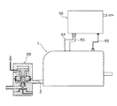
そこで、従来から流体制御装置が種々提案されており、図7に示すような純水温度を可変とした場合の流量制御を行う純水流量の制御装置151があった(例えば、特許文献1参照。)。その構成は、純水流量を調整するために操作圧の作用を受けて開度調節される流量調整弁152と、流量調整弁152に供給される操作圧を調整するための操作圧調整弁153と、流量調整弁152から出力される純水流量を計測するための流量計測器154と、流量計測器154を通った純水の流れを許容又は遮断するための開閉弁155とを備え、操作圧調整弁153により調整される操作圧と、流量調整弁152における純水の出力圧力とを均衡させることにより、流量調整弁152から出力される純水流量を一定に制御するようにした制御装置151であって、流量計測器154による計測値が一定となるように、その計測値に基づいて操作圧調整弁153から流量調整弁152に供給される操作圧をフィードバック制御するための制御回路を設けたことを特徴とするものであった。その効果は、純水の温度変化に伴って流量調整弁152における出力圧力が変化したとしても、その変化分に対応して操作圧がリアルタイムに調整されることで、流量調整弁152から出力される純水流量が調整されるため、純水流量を高精度に一定値に保つことができるものであった。
Thus, various fluid control devices have been proposed in the past, and there has been a pure water flow
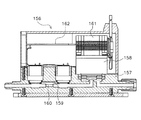
また、流体制御を行うモジュールとして、図8に示すような流体を移送する流体回路にインライン接続される流体制御モジュール156があった(例えば、特許文献2参照。)。その構成は、化学的に不活性な流路を有するハウジング157と、流路に接続された調節可能な制御弁158と、流路に接続された圧力センサ159と、流路内に位置する絞り部160とを備え、制御弁158と圧力センサ159がハウジング157内に収容され、さらに制御弁158の駆動を行う機械的、電気的、または空気的な構成を有するドライバ161と、制御弁158及び圧力センサ159に電気的に接続されるコントローラ162がハウジング157内に収容されているものであった。その効果は、流体回路内で測定された圧力差と絞り部160の直径とから流路内の流量を測定し、測定した流量に基いて制御弁158をフィードバック制御して駆動することで、流路内の流量を高精度に決定することができるものであった。
Further, as a module that performs fluid control, there is a
しかしながら、前記従来の純水流量の制御装置151は、構成要素が多岐に分割されているため、半導体製造装置内等に設置する際に、各構成要素の配管接続作業、電気配線やエア配管作業をそれぞれ行なわなくてはならず、作業が煩雑で時間を要するばかりでなく、配管や配線ミスが生じる恐れがあるという問題があった。また、配管接続時にチューブや継手などを介して接続されるため接続部分による圧力損失が生じてしまい、この圧力損失が流量計測に影響して流量の測定誤差が大きくなり、正確な流量による制御が困難になるという問題があった。さらに、腐食性流体を使用した場合、腐食性ガスの透過により流量計測器154内の部品が腐食する恐れがあった。
However, since the conventional pure water flow
また、前記従来の流量制御モジュール156では、流体に腐食性流体を使用した場合、透過した腐食性ガスが流量制御モジュール156内に充満すると、コントローラ162やドライバ161を腐食してしまい、流量計測や流量制御の作動に影響して正確な流量制御ができなくなったり、最悪の場合は破損したりする恐れがあった。その際、モジュールの故障原因がコントローラ162やドライバ161の腐食によるものであっても、各部品が一体的に設計された流量制御モジュール156は、各部品ごと個別に修理や交換をするのが困難であるため、モジュール全部を交換する必要が生じ、破損修理のコストが嵩むという問題があった。また、流体制御装置に流入する流体が圧力変動周期の速い脈動した流れであった場合、制御弁158は脈動した流体に対して流量を制御しようと作動するが、ハンチングを起こし流量制御ができなくなるという問題もあり、この状態を継続すると終にはドライバ161や制御弁158が破損してしまうという問題があった。
Further, in the conventional
本発明は、以上のような従来技術の問題点に鑑みなされたものであり、半導体製造装置内等への設置、配管及び配線接続が容易であり、配線接続による圧力損失を低減し、各モジュールの配置変更を容易に行なうもので、また流体に腐食性流体を使用しても腐食が発生せず、流入する流体が脈動していても流量の制御が可能な流体制御装置を提供することを目的とする。 The present invention has been made in view of the above-described problems of the prior art, and can be easily installed in a semiconductor manufacturing apparatus or the like, connected to piping and wiring, reduces pressure loss due to wiring connection, and each module. The present invention provides a fluid control device that can easily change the arrangement of the fluid, and that does not generate corrosion even when a corrosive fluid is used as the fluid, and that can control the flow rate even when the flowing fluid pulsates. Objective.
上記課題を解決するための本発明の構成を図1、図2に基づいて説明すると、超音波を流体中に発信する第一超音波振動子(12)と、第一超音波振動子(12)から発信した超音波を受信し信号を流量計アンプ部(58)に出力する第二超音波振動子(13)とを有する流量計センサ部(4)と、操作圧に応じて流体の流量を一定に調節する流量調節弁(5)とを具備し、少なくとも流量計センサ部(4)と調節弁(5)とが、流体流入口(3)と流体流出口(6)を有する1つの第一のケーシング(2)内に接続されて設置されてなるバルブモジュール(1)と、流量計センサ部(4)の信号によって流量を演算する流量計アンプ部(58)と、調節弁(5)の操作圧を調整する電空変換器(60)と、流量計アンプ部(58)で演算された流量値に基づいて操作圧を調整しフィードバック制御するための制御部(59)とが1つの第二のケーシング(57)内に設置されてなる電装モジュール(56)とが、2つに分かれて構成され、前記電装モジュール(56)の第二のケーシング(57)内が略密閉され、前記調節弁(5)が、上部に弁室(23)と、弁室(23)に各々が連通している入口流路(24)および出口流路(25)とを有し、弁室底部中央に出口流路(25)が連通している開口部(26)が設けられた本体(14)と、底部中央に貫通孔(28)と、側面に呼吸口(29)が設けられ、本体(14)と第一ダイヤフラム(17)を挟持固定しているシリンダー(15)および上部に作動流体連通口(30)と側面に排出口(31)が設けられ、シリンダー(15)と第二ダイヤフラム(19)の周縁部を挟持固定しているボンネット(16)が一体的に固定されており、第一ダイヤフラム(17)は肩部(32)と、肩部(32)の上に位置し後記ロッド(20)の下部に嵌合固定される取り付け部(33)、肩部(32)の下に位置し後記弁体(18)が固定される接合部(45)、肩部(32)から径方向に延出した薄膜部(34)、薄膜部(34)に続く厚肉部(35)および厚肉部(35)の周縁部に設けられたシール部(36)が一体的に形成され、接合部(45)には弁室(23)の開口部(26)に後記ロッド(20)の上下動に伴って出入りする弁体(18)が固定されており、一方、第二ダイヤフラム(19)は中央穴(37)を有し、その周辺の厚肉部(38)と、厚肉部(38)から径方向に延出した薄膜部(39)および薄膜部(39)の周縁部に設けられたシール部(40)が一体的に形成され、底部に第一ダイヤフラム(17)の取り付け部(33)が固定されているロッド(20)の上部に位置する肩部(42)にダイヤフラム押え(21)により中央穴(37)を貫通して挟持固定されており、また、ロッド(20)は、その下方部がシリンダー(15)底部の貫通孔(28)内に遊嵌状態に配置され、かつ、シリンダー(15)の段差部(48)とロッド(20)の肩部(42)下面との間に径方向への移動が防止された状態で嵌合されたスプリング(22)で支承されているように配置されていることを第1の特徴とする。 The configuration of the present invention for solving the above problems will be described with reference to FIGS. 1 and 2. A first ultrasonic transducer (12) that transmits ultrasonic waves into a fluid, and a first ultrasonic transducer (12 ) And a flowmeter sensor unit (4) having a second ultrasonic transducer (13) for receiving the ultrasonic wave transmitted from the flowmeter and outputting a signal to the flowmeter amplifier unit (58), and the flow rate of the fluid according to the operating pressure. A flow rate control valve (5) that adjusts the flow rate constant, and at least the flow meter sensor part (4) and the control valve (5) have one fluid inlet (3) and one fluid outlet (6). A valve module (1) connected and installed in the first casing (2), a flow meter amplifier unit (58) for calculating a flow rate based on a signal from the flow meter sensor unit (4), and a control valve (5) ) Is calculated by the electropneumatic converter (60) that adjusts the operating pressure of the flowmeter and the flow meter amplifier (58). The control unit (59) for adjusting the operation pressure based on the flow rate value and performing feedback control and the electrical module (56) installed in one second casing (57) are divided into two parts configured Te, the second casing (57) within the electrical module (56) is substantially sealed, said control valve (5) is a valve chamber (23) at the top, each communicating with a valve chamber (23) A main body (14) having an inlet channel (24) and an outlet channel (25), and having an opening (26) communicating with the outlet channel (25) at the center of the bottom of the valve chamber And a through hole (28) in the center of the bottom and a breathing port (29) on the side, and a working fluid communication with the cylinder (15) and the upper part sandwiching and fixing the main body (14) and the first diaphragm (17). An outlet (31) is provided on the side (30) and side, and a cylinder ( 15) and the bonnet (16) which clamps and fixes the peripheral part of the second diaphragm (19) are integrally fixed, and the first diaphragm (17) has a shoulder part (32) and a shoulder part (32). An attachment part (33) which is located above and is fitted and fixed to the lower part of the rod (20), a joint (45) which is located below the shoulder part (32) and to which the valve body (18) is fixed, The thin film part (34) extending in the radial direction from the shoulder part (32), the thick part (35) following the thin film part (34), and the seal part (36) provided at the peripheral part of the thick part (35) Is integrally formed, and a valve body (18) that moves in and out as the rod (20) moves up and down is fixed to the opening (26) of the valve chamber (23) at the joint (45), On the other hand, the second diaphragm (19) has a central hole (37), and has a thick part (38) and a thick part ( 8) The thin film portion (39) extending in the radial direction and the seal portion (40) provided at the peripheral edge of the thin film portion (39) are integrally formed, and the attachment portion of the first diaphragm (17) is formed at the bottom The center hole (37) is clamped and fixed to the shoulder (42) located above the rod (20) to which the (33) is fixed by the diaphragm presser (21), and the rod (20) The lower part of the cylinder (15) is arranged in a loosely fit state in the through hole (28) at the bottom of the cylinder (15), and the step (48) of the cylinder (15) and the shoulder (42) lower surface of the rod (20) It is the 1st characteristic that it arrange | positions so that it may be supported by the spring (22) fitted in the state from which the movement to radial direction was prevented between .
前記電装モジュール(56)の第二のケーシング(57)内が略密閉され、電空変換器(60)から第二のケーシング(57)内に充填された気体の排出のみに使用される排出口(67)を有することを第2の特徴とする。 The second casing (57) of the electrical module (56) is substantially sealed, and is used only for discharging the gas filled in the second casing (57) from the electropneumatic converter (60). (67) is a second feature.
また、前記流量計センサ部(4)と流量計アンプ部(58)とを接続するケーブル(64、65)が、コネクタ(53、54、61、62)を介して前記流量計センサ部(4)および/または流量計アンプ部(58)と脱着可能にされていることを第3の特徴とする。 Cables (64, 65) connecting the flow meter sensor unit (4) and the flow meter amplifier unit (58) are connected to the flow meter sensor unit (4) via connectors (53, 54, 61, 62). ) And / or the flowmeter amplifier section (58) is detachable .
また、前記流量計センサ部(4)と流量計アンプ部(58)と接続するケーブル(64、65)が、コネクタ(53、54、61、62)を介して流量計センサ部(4)および/または流量計アンプ部(58)と脱着可能に設けられ、前記バルブモジュール(1)の第一のケーシング(2)にコネクタボックス(50)が略密閉状態で設けられ、コネクタボックス(50)に調節弁(5)の排出口(31)と連通する吸気孔(51)と、第一のケーシング(2)外と連通する排気孔(52)が設けられていることを第4の特徴とする。 The cables (64, 65) connecting the flow meter sensor unit (4) and the flow meter amplifier unit (58) are connected to the flow meter sensor unit (4) and the connector via the connectors (53, 54, 61, 62). And / or a detachable attachment to the flow meter amplifier section (58), a connector box (50) is provided in a substantially sealed state in the first casing (2) of the valve module (1), and a connector box (50) is provided. and the outlet (31) and communicating with the intake hole of the regulating valve (5) (51), and that the first casing (2) outside the communication with the exhaust hole (52) is found provided the fourth aspect To do.
また、流体流入口(3)に連通する入口流路(7)と、入口流路(7)から垂設された第一立上り流路(8)と、第一立上り流路(8)に連通し入口流路(7)軸線に略平行に設けられた直線流路(9)と、直線流路(9)から垂設された第二立上り流路(10)と、第二立上り流路(10)に連通し入口流路(7)軸線に略平行に設けられ調節弁(5)の入口流路(24)に連通する出口流路(11)とが連続して設けられ、第一、第二立上り流路(8、10)の側壁の直線流路(9)の軸線と交わる位置に、一対の超音波振動子(12、13)が互いに対向して配置された流量計センサ部(4)と、一対の超音波振動子(12、13)がケーブル(64、65)を介して接続される流量計アンプ部(58)から構成される流量計測器が、一対の超音波振動子(12、13)の送受信を交互に切り替えて各々の超音波振動子(12、13)間の超音波伝搬時間差を測定することにより直線流路(9)を流れる流体の流量を演算するように構成された超音波流量計であることを第5の特徴とする Further, the inlet channel (7) communicating with the fluid inlet (3), the first rising channel (8) suspended from the inlet channel (7), and the first rising channel (8) are communicated. A straight channel (9) provided substantially parallel to the axis of the inlet channel (7), a second rising channel (10) suspended from the linear channel (9), and a second rising channel ( 10) is connected to the inlet channel (7) substantially parallel to the axis, and is continuously provided with the outlet channel (11) communicating with the inlet channel (24) of the control valve (5). A flowmeter sensor unit (a pair of ultrasonic transducers (12, 13)) is disposed at a position intersecting with the axis of the straight channel (9) on the side wall of the second rising channel (8, 10). 4) and a flow meter comprising a flow meter amplifier unit (58) to which a pair of ultrasonic transducers (12, 13) are connected via cables (64, 65), By alternately switching between transmission and reception of the pair of ultrasonic transducers (12, 13) and measuring the ultrasonic propagation time difference between the ultrasonic transducers (12, 13), the fluid flowing through the straight flow path (9) the ultrasonic flowmeter der Rukoto that is configured to calculate the flow rate of the fifth feature
また、流体流入口(3)に連通する入口流路(71)と、入口流路(71)内に垂設されたカルマン渦を発生させる渦発生体(72)と、出口流路(73)とを備える直線流路(74)とが連続して設けられ、直線流路(74)の渦発生体(72)の下流側の側壁に、一対の超音波振動子(75、76)が流路軸線方向に直交する位置に互いに対向して配置された流量計センサ部(68)と、これら超音波振動子(75、76)がケーブル(86、87)を介して接続される流量計アンプ部(80)から構成される流量計測器が、渦発生体(72)の下流に発生するカルマン渦の発生周波数を一方の超音波振動子(75)が送信した信号と他方の超音波振動子(76)が受信した信号との位相差によって流量を演算するように構成された超音波式渦流量計であることを第6の特徴とする。 Also, an inlet channel (71) communicating with the fluid inlet (3), a vortex generator (72) that generates Karman vortices suspended in the inlet channel (71), and an outlet channel (73) And a pair of ultrasonic transducers (75, 76) flow on the downstream side wall of the vortex generator (72) of the linear channel (74). A flow meter amplifier in which a flow meter sensor unit (68) disposed opposite to each other at a position orthogonal to the road axis direction and these ultrasonic transducers (75, 76) are connected via cables (86, 87). The flow rate measuring device composed of the section (80) transmits a signal transmitted from one ultrasonic transducer (75) to the generation frequency of Karman vortex generated downstream of the vortex generator (72) and the other ultrasonic transducer. (76) is configured ultrasonic sound to compute the flow rate by a phase difference between the received signal And sixth aspect of that it is a type vortex flowmeter.
また、 バルブモジュール(1)の流体流入口(3)の内部または外部に圧力制御弁(88)が設けられたことを第7の特徴とする。 A seventh feature is that a pressure control valve (88) is provided inside or outside the fluid inlet (3) of the valve module (1) .
前記バルブモジュール1の流体流入口3の内部または外部に圧力制御弁88が設けられたことを第9の特徴とする。
A ninth feature is that a
本発明においては、少なくとも、流量計センサ部4と、調節弁5とが1つのケーシング2内に接続されてなる構成であれば良い。これは流量センサ部4と調節弁5が一体化されることで流体制御装置をコンパクトに設けることができ、配管接続が容易となるとともに、継手などによる接続部分が少なくて済むので接続部分による圧力損失を低減することができる。
In the present invention, at least the
調節弁5は、操作圧により流量が調節ができるものであれば特に限定されるものではないが、本発明の調節弁5の構成を有しているものが好ましく、作動流体連通口30に作動流体を導入することで流量の調節が容易で、流体を所望の流量に広範囲に亘って調節することができる。また第一ダイヤフラム17の薄膜部の受圧面積が第二ダイヤフラム19の薄膜部の受圧面積よりも極めて小さいため、入口流路24からの流体の圧力が変化しても流体の圧力の影響を受けにくくハンチングが生じにくい。また、ロッド20の下方部がシリンダー15底部の貫通孔に遊嵌されているため配管内の流量の増減に対する流量制御の応答性に優れている。また、摺動部がないので、摩擦による擦れやそれが原因で生じる摺動カスなども出ない。調節弁5の部品のうち腐食の可能性があるスプリング22は全表面をフッ素系樹脂で被覆されているので腐食が防止される。
The
また、本発明においてバルブモジュール1の流量計センサ部4と電装モジュール56の流量計アンプ部58とはケーブル64、65で直接接続してもよいが、流量計センサ部4に繋がったコネクタ53、54および流量計アンプ部58に繋がったコネクタ61、62を介して流量計センサ部4と流量計アンプ部58をケーブル64、65で接続することが好ましい。このときコネクタは流量計センサ部4に繋がったコネクタ53、54のみ設けてもよく、流量計アンプ部58に繋がったコネクタ61、62のみ設けてもよく、両方設けてもかまわない。このように、ケーブル64、65をコネクタを介して脱着可能接続することにより、流体制御装置の配線接続が容易にかつ短時間で行なうことができるとともに、各モジュールの配置換えも容易に行うことができる。
In the present invention, the flow
また、本発明のバルブモジュール1のケーシング2にはコネクタボックス50を設けてもよい。調節弁5の排出口31から排出される不活性ガスや空気がコネクタボックス50の吸気孔51からコネクタボックス50内に供給され、排気孔52から排出されることで、流体に腐食性流体を使用した場合に腐食性ガスがコネクタボックス50内に透過したとしても、吸気孔51から排気孔52への気流に乗って排出され、コネクタボックス50内部に貯留されることが無く、コネクタ53、54の腐食が防止される。
Further, a
また、流量計センサ部4と流量計アンプ部58で構成される流量計測器は、計測した流量を電気信号に変換して制御部59に出力されるものなら特に限定されないが、超音波流量計、超音波式渦流量計であることが好ましく、特に本発明の超音波流量計、超音波式渦流量計の構成を有しているものがより好ましい。本発明の超音波流量計の場合、微小流量に対して精度良く流量測定ができるため、微小流量の流体制御に好適である。また本発明の超音波式渦流量計の場合、大流量に対して精度良く流量測定ができるため、大流量の流体制御に好適である。このように、流体の流量に応じて超音波流量計と超音波式渦流量計を使い分けることで精度の良い流体制御を行うことができる。
Further, the flow rate measuring device configured by the flow
また、本発明のケーシング2、流体流入口3、超音波振動子12、13を除いた流量計センサ部4、調節弁5の各部品、流体流出口6、電装モジュール56のケーシング57の材質は、樹脂製であれば塩化ビニル、ポリプロピレン、ポリエチレンなどいずれでも良いが、特に流体に腐食性流体を用いる場合はポリテトラフルオロエチレン(以下、PTFEと記す)、ポリビニリデンフルオロライド(以下、PVDFと記す)、テトラフルオロエチレン・パーフルオロアルキルビニルエーテル共重合樹脂(以下、PFAと記す)などのフッ素樹脂であることが好ましく、フッ素樹脂製であれば腐食性ガスが透過しても各部品の腐食の心配がない。
The material of the
また、本発明のバルブモジュール1は、流体流入口3、流量計センサ部4、調節弁5、流体流出口6が設置されているが、腐食の恐れのない材質のものであれば開閉弁、温度計など他の配管部材を設けてもかまわない。また電装モジュール56も、流量計アンプ部58、制御部59、電空変換器60が設置されているが、他の電装部品を設けてもかまわない。
Further, the
本発明は以上のような構造をしており、以下の優れた効果が得られる。
(1)バルブモジュールと電装モジュールとに二分割して構成されているため、流体に腐食性流体を使用した場合に腐食性ガスが透過したとしても、腐食の恐れのある部品を有する電装モジュールは、腐食性流体が流れるバルブモジュールから隔離することができ腐食することがない。
(2)流体制御を行なう各部品が、バルブモジュールと電装モジュールとにそれぞれ設置されて二分割して構成され、コネクタを介して脱着可能に配線接続されることにより、半導体製造装置内などへの設置、配管及び配線接続が容易で短時間に行なうことができるとともに、各モジュールの配置換えも容易に行うことができる。
(3)本発明の構成の調節弁を用いることにより、コンパクトな構造でかつ流量の調節が容易で、流体を所望の流量に広範囲に亘って調節することができる。
(4)本発明構成の調節弁を用いることにより、第一ダイヤフラムの薄膜部の受圧面積が第二ダイヤフラムの薄膜部の受圧面積よりも極めて小さいため、入口流路からの流体の圧力の影響を受けにくくハンチングが生じにくい。
(5)本発明の構成の調節弁は、ロッドの下方部がシリンダー底部の貫通孔に遊嵌されているため配管内の流量の増減に対する流量制御の応答性に優れている。
(6)本発明の構成の超音波流量計を用いることにより、微小流量の流体が流れているときに正確で安定した流体制御を行なうことができる。
(7)本発明の構成の超音波式渦流量計を用いることにより、大きな流量の流体が流れているときに正確で安定した流体制御を行なうことができる。
(8)バルブモジュールの内部または外部に圧力制御弁を設けることにより、流体を一定圧に制御することができるため、流入する流体が圧力変動周期の速い脈動した流れであったとしても、安定した圧力制御を行い、流入する流体の流量を一定値となるようにすることができる。
The present invention has the structure as described above, and the following excellent effects can be obtained.
(1) Since the valve module and the electrical module are divided into two parts, even if a corrosive gas permeates when a corrosive fluid is used as the fluid, the electrical module having parts that may be corroded Corrosive fluid can be isolated from the flowing valve module and will not corrode.
(2) Each component that performs fluid control is installed in a valve module and an electrical module, and is divided into two parts, and is detachably connected via a connector so that it can be connected to a semiconductor manufacturing apparatus. The installation, piping and wiring connection are easy and can be performed in a short time, and the rearrangement of each module can be easily performed.
(3) By using the control valve having the configuration of the present invention, the flow rate can be easily adjusted with a compact structure, and the fluid can be adjusted to a desired flow rate over a wide range.
(4) Since the pressure receiving area of the thin film portion of the first diaphragm is extremely smaller than the pressure receiving area of the thin film portion of the second diaphragm by using the control valve of the present invention configuration, the influence of the pressure of the fluid from the inlet channel is reduced. Less susceptible to hunting.
(5) Since the lower part of the rod is loosely fitted in the through hole at the bottom of the cylinder, the control valve having the configuration of the present invention is excellent in the responsiveness of the flow rate control with respect to the increase and decrease of the flow rate in the pipe.
(6) By using the ultrasonic flowmeter having the configuration of the present invention, accurate and stable fluid control can be performed when a minute flow rate of fluid is flowing.
(7) By using the ultrasonic vortex flowmeter having the configuration of the present invention, accurate and stable fluid control can be performed when a large flow rate of fluid is flowing.
(8) By providing a pressure control valve inside or outside the valve module, the fluid can be controlled to a constant pressure, so that even if the inflowing fluid has a pulsating flow with a fast pressure fluctuation cycle, it is stable. Pressure control can be performed so that the flow rate of the inflowing fluid becomes a constant value.
以下、本発明の実施の形態について図面に示す実施例を参照して説明するが、本発明が本実施例に限定されないことは言うまでもない。図1は本発明の第一の実施例を示す流体制御装置の縦断面図である。図2は図1の調節弁の要部拡大図である。図3は本発明の第二の実施例を示す流体制御装置の縦断面図である。図4は図3のA−A断面図である。図5は本発明の第三の実施例を示す流体制御装置の一部縦断面図である。図6は図5の圧力制御弁の要部拡大図である。 Hereinafter, embodiments of the present invention will be described with reference to examples shown in the drawings. However, it is needless to say that the present invention is not limited to the examples. FIG. 1 is a longitudinal sectional view of a fluid control apparatus showing a first embodiment of the present invention. FIG. 2 is an enlarged view of a main part of the control valve of FIG. FIG. 3 is a longitudinal sectional view of a fluid control apparatus showing a second embodiment of the present invention. 4 is a cross-sectional view taken along the line AA in FIG. FIG. 5 is a partial longitudinal sectional view of a fluid control apparatus showing a third embodiment of the present invention. FIG. 6 is an enlarged view of a main part of the pressure control valve of FIG.
以下、図1、図2に基づいて本発明の第一の実施例である流体制御装置について説明する。 Hereinafter, a fluid control apparatus according to a first embodiment of the present invention will be described with reference to FIGS.
1はバルブモジュールである。バルブモジュール1は、ケーシング2、流体流入口3、流量計センサ部4、調節弁5、流体流出口6から形成され、各々の構成は以下の通りである。
2はPVDF製のケーシングである。ケーシング2内には、ケーシング2の底面に流量計センサ部4、調節弁5がボルト、ナット(図示せず)にて固定されており、流体流入口3、流量計センサ部4、調節弁5、流体流出口6の順で連続して接続された状態で設置されている。また、ケーシング2には後記コネクタボックス50が密閉状態で設けられている。なお、流量計センサ部4、調節弁5は順序を逆にしてもかまわない。
2 is a PVDF casing. In the
3はPTFE製の流体流入口である。流体流入口3は後記流量計センサ部4の入口流路7に連通している。
3 is a PTFE fluid inlet. The fluid inflow port 3 communicates with an
4は流体の流量を計測する流量計センサ部である。流量計センサ部4は、流体流入口3に連通する入口流路7と、入口流路7から垂設された第一立上り流路8と、第一立上り流路8に連通し入口流路7軸線に略平行に設けられた直線流路9と、直線流路9から垂設された第二立上り流路10と、第二立上り流路10に連通し入口流路7軸線に略平行に設けられた出口流路11とを有し、第一、第二立上り流路8、10の側壁の直線流路9の軸線と交わる位置に、第一及び第二の超音波振動子12、13が互いに対向して配置されている。第一及び第二の超音波振動子12、13はフッ素樹脂で覆われており、該振動子12、13から伸びた配線は後記コネクタボックス50内のコネクタ53、54に繋がっている。なお、流量計センサ部4の各々の超音波振動子12、13以外はPFA製である。
5は操作圧に応じて流体の流量を調節する調節弁である。調節弁5は本体14、シリンダー15、ボンネット16、第一ダイヤフラム17、弁体18、第二ダイヤフラム19、ロッド20、ダイヤフラム押え21、スプリング22で構成される。
14はポリテトラフルオロエチレン(以下、PTFEと記す)製の本体であり、上部に円筒状の弁室23が設けられており、その弁室23に連通して入口流路24及び出口流路25が各々下部に設けられている。弁室底部中央には出口流路25に繋がる開口部26が、開口部26の周辺部には入口流路24に繋がる開口部27が設けられている。開口部27の横断面形状は円形であるが、流量を広範囲に亘って制御するために開口部26を大きくした場合は、弁室底部中央に設けられた開口部26を中心とした周辺部に略三日月状に形成されることが望ましい。本体14の上面には第一ダイヤフラム17のシール部が嵌合される環状溝43が設けられている。
14 Poritetorafu Ruoro ethylene (hereinafter referred to as PTFE) is a body made of, has a
15はポリ塩化ビニル(以下、PVCと記す)製のシリンダーであり、底部中央に貫通孔28と底部内面に段差部48を有し、側面に呼吸口29が設けられている。シリンダー15は、本体14と第一ダイヤフラム17の周縁部を挟持固定し、ボンネット16と第二ダイヤフラム19の周縁部を挟持固定している。シリンダー15の側面に設けられた呼吸口29は、流体がガスとなって第一ダイヤフラム17を透過した場合に、そのガスを排出するために設けられている。
15 is a cylinder made of polyvinyl chloride (hereinafter referred to as PVC), which has a through
16はPVC製のボンネットであり、上部に空気や油などの作動流体を導入する作動流体連通口30及び排出口31が設けられている。本実施例では作動流体連通口30はボンネット16の上部に設けられているが、側面に設けても良い。また周側部の下部には第二ダイヤフラム19のシール部40が嵌合される環状溝44が設けられている。以上説明した本体14、シリンダー15およびボンネット16はボルト、ナット(図示しない)によって一体的に固定されている。
16 is a hood made of PVC, the working
17はPTFE製の第一ダイヤフラムであり、肩部32を中心に肩部32の上の位置にロッド20に嵌合固定される取り付け部33が、また、下の位置には弁体18が固定される接合部45が一体的にかつ突出して設けられており、また肩部32から径方向に延出した部分には薄膜部34と、薄膜部34に続く厚肉部35および厚肉部35の周縁部にシール部36が設けられており、これらは一体的に形成されている。薄膜部34の膜厚は厚肉部35の厚さの1/10程度にされている。ロッド20と取り付け部33の固定の方法は嵌合だけでなく螺合でも接着でもよい。接合部45と弁体18の固定は螺合が好ましい。第一ダイヤフラム17の外周縁部に位置するシール部36は軸線方向に断面L字状に形成されており、O−リング49を介して本体14の環状溝43に嵌合され、シリンダー15の底部に設けられた環状突部41に押圧されて挟持固定されている。
18はPTFE製の弁体であり、第一ダイヤフラム19の下部に設けられた接合部45に螺合固定されている。弁体18は本実施例のような形状に限らず所望の流量特性に応じて、球状弁体や円錐形状弁体でも良い。さらには摺動抵抗を極力少なくした状態で全閉を行う為には外周リブ付き弁体が好適に用いられる。
19はエチレンプロピレンジエン共重合体(以下、EPDMと記す)製の第二ダイヤフラムであり、中央穴37を有し、その周辺の厚肉部38、厚肉部の上部には環状突部41、厚肉部38から径方向に延出した薄膜部39および薄膜部39の周縁部に設けられたシール部40が一体的に形成され、底部に第一ダイヤフラム17の取り付け部33が固定されているロッド20の上部に位置する肩部42にダイヤフラム押え21により中央穴37を貫通して挟持固定されている。本実施例では材質がEPDM製を用いているが、フッ素系のゴムまたはPTFE製でも良い。
20はPVC製のロッドであり、上部には拡径された肩部42が設けられている。肩部42の中央にはダイヤフラム押え21の接合部47が螺合され、第二ダイヤフラム19を挟持固定している。下方部はシリンダー15底部の貫通孔28内に遊嵌状態に配置され、下端部には第一ダイヤフラム17の取り付け部33が固定されている。また、ロッド20の肩部42の下面とシリンダー15の段差部48との間にはスプリング22が嵌合されている。
21はPVC製のダイヤフラム押えであり、下面中央にはロッド20と螺合にて接続される接合部47が設けられている。また、下面には第二ダイヤフラム19の環状突部41と嵌合される環状溝46が設けられている。
22はSUS製のスプリングであり、ロッド20の肩部42の下面とシリンダー15の段差部48との間に径方向への移動が阻止された状態で嵌合され支承されている。また、肩部42の下面を常に上方へ付勢している。スプリング22の全表面はフッ素系樹脂で被覆されている。尚、スプリング22は調節弁の口径や使用圧力範囲によってバネ定数を変えて適宜使用でき、複数本使用してもよい。
6はPTFE製の流体流出口である。 6 is a PTFE fluid outlet.
50はケーシング2に密閉されて設けられたPVDF製のコネクタボックスである。コネクタボックス50は、ケーシング2内に連通する吸気孔51と、ケーシング2外に連通する排気孔52が設けられ、吸気孔51はチューブを介して前記調節弁5の排出口31と接続されている。コネクタボックス50内には超音波振動子12、13から伸びた配線に繋がったコネクタ53、54が配置され、コネクタ53、54は後記電装モジュール56の流量計アンプ部58から伸びた配線と接続されたケーブル64、65のコネクタにそれぞれ脱着可能に接続されている。
また、ケーシング2には、調節弁5の作動流体連通口30に伸びる配管に繋がったエアコネクタ55が、接続部分がケーシング2外表面から突出するように固着されている。
Further, an
56は電装モジュールである。電装モジュール56は、ケーシング57、流量計アンプ部58、制御部59、電空変換器60から形成され、その各々の構成は以下の通りである。
ケーシング57はPVDF製である。ケーシング57内には流量計アンプ部58、制御部59および電空変換器60が密閉状態で設置されている。また、ケーシング57は外部から不活性ガスや空気が電空変換器60へ供給され、電空変換器60からケーシング57内に圧縮空気が供給される。図中、67は排出口である。
The
流量計アンプ部58は前記流量計センサ部4から出力された信号から流量を演算する演算部を有している。演算部は、送信側の第一超音波振動子12に一定周期の超音波振動を出力する発信回路と、受信側の第二超音波振動子13からの超音波振動を受信する受信回路と、各超音波振動の伝搬時間を比較する比較回路と、比較回路から出力された伝搬時間差から流量を演算する演算回路とを備えている。
The flow
制御部59は流量計アンプ部58から出力された流量に対して、設定された流量になるようにフィードバック制御して、後記電空変換器60の操作圧を増減制御する制御回路を有している。
The
電空変換器60は不活性ガスや空気の操作圧を調整する。電空変換器60は操作圧を比例的に調整するために電気的に駆動する電磁弁から構成され、前記制御部59からの制御信号に応じて調節弁5の操作圧を調整する。
The
また、ケーシング57には、流量計アンプ部58から伸びた配線に繋がったコネクタ61、62の接続部分がケーシング57外表面から突出するように固着されている。同様に、電空変換器60から伸びた配管に繋がったエアコネクタ63の接続部分もケーシング57外表面から突出するように固着されている。
In addition, a connection portion of
バルブモジュール1と電装モジュール56は、ケーブル64、65のコネクタを各モジュール1、56の各々のコネクタ53、54、61、62にそれぞれ脱着可能に接続させ、チューブ66を各モジュール1、56の各々のエアコネクタ55、63に脱着可能に接続させることで、二つに分かれて構成される。なお、本発明のケーブルは2本であるが1本にまとめてもよく、この場合コネクタも各モジュール1、56に1個ずつ設けられる。
The
次に、本発明の第一の実施例の作動について説明する。 Next, the operation of the first embodiment of the present invention will be described.
バルブモジュール1の流体流入口3から流入した流体は、まず流量計センサ部4に流入する。流量計センサ部4に流入した流体は、直線流路9で流量が計測される。流体の流れに対して上流側に位置する第一超音波振動子12から下流側に位置する第二超音波振動子13に向かって超音波振動を伝搬させる。第二超音波振動子13で受信された超音波振動は電気信号に変換され、流量計アンプ部58の演算部へ出力される。超音波振動が上流側の第一超音波振動子12から下流側の第二超音波振動子13へ伝搬して受信されると、瞬時に演算部内で送受信が切換えられて、下流側に位置する第二超音波振動子13から上流側に位置する第一超音波振動子12に向かって超音波振動を伝搬させる。第一超音波振動子12で受信された超音波振動は、電気信号に変換され、流量計アンプ部58の演算部へ出力される。このとき、超音波振動は直線流路9内の流体の流れに逆らって伝搬していくので、上流側から下流側へ超音波振動を伝搬させるときに比べて流体中での超音波振動の伝搬速度が遅れ、伝搬時間が長くなる。出力された相互の電気信号は流量計アンプ部58の演算部内で伝搬時間が各々計測され、伝搬時間差から流量が演算される。流量計アンプ部58で演算された流量は電気信号に変換されて制御部59に出力される。
The fluid flowing in from the fluid inlet 3 of the
次に流量計センサ部4を通過した流体は調節弁5に流入する。制御部59では予め設定された所定の流量に対して、リアルタイムに計測された流量との偏差から、偏差をゼロにするように信号を電空変換器60に出力し、電空変換器60はそれに応じた操作圧を調節弁5に供給し駆動させる。調節弁5から流出する流体は、流量を設定流量で一定値となるように、つまり設定流量と計測された流量の偏差がゼロに収束されるように調節弁5で制御される。
Next, the fluid that has passed through the flow
ここで、電空変換器60から供給される操作圧に対する調節弁5の作動について説明する。
Here, the operation of the
調節弁は、ボンネット16の上部に設けられた作動流体連通口30から供給される圧縮空気がゼロの状態、すなわち開状態であり、流体の流量が最大の場合を示している。この時、弁体18はシリンダー15の段差部48とロッド20の肩部42の下面との間に嵌合されたスプリング22の付勢力により、ロッド20の上部に接合されているダイヤフラム押え21の上部が、ボンネット16の底面に接する位置で静止している。
The control valve is in a state where the compressed air supplied from the working
この状態において、作動流体連通口30から供給される圧縮空気の圧力を高くしていくと、シール部40がボンネット16に嵌合されている第二ダイヤフラム19の薄膜部39とボンネット16によってボンネット16の内部は密閉されているため、圧縮空気はダイヤフラム押え21と第二ダイヤフラム19を下方に押し下げ、ロッド20と第一ダイヤフラム17を介して弁体18が開口部26の間に挿入されていく。ここで、作動流体連通口30から供給される圧縮空気の圧力を一定にすると弁体18は、スプリング22の付勢力と第一ダイヤフラム17の薄膜部34の下面と弁体18の下面が流体から受ける圧力と釣り合う位置にて静止する。したがって、開口部26は挿入される弁体18により開口面積が減少するため、流体の流量も減少する。
In this state, when the pressure of the compressed air supplied from the working
さらに作動流体連通口30から供給される圧縮空気の圧力を高くしていくと、弁体18はさらに押し下げられ、終には開口部26と接触し全閉状態となる。
When the pressure of the compressed air supplied from the working
また、圧縮空気を排出していくと、シール部40がボンネット16に嵌合されている第二ダイヤフラム19の薄膜部39とボンネット16によって密閉されているボンネット16の内部は圧力が下がり、スプリング22の付勢力の方が大きくなりロッド20を押し上げる。ロッドが上昇することにより、第一ダイヤフラム17を介して固定されている弁体18も上昇し、調節弁は開状態となる。
As the compressed air is discharged, the pressure in the
以上の作動により、バルブモジュール1の流体流入口3に流入する流体は、設定流量で一定になるように制御され、流体流出口6から流出される。この流量計センサ部4および流量計アンプ部58からなる超音波流量計は、流体の流れ方向に対する伝搬時間差から流量を計測するため微小流量でも正確に流量を計測でき、また調節弁5は上記構成によりコンパクトで安定した流量調節が行えるため、微小流量の流量調節に優れた効果を発揮する。
With the above operation, the fluid flowing into the fluid inlet 3 of the
次に本発明の第一の実施例で使用される流体が腐食性流体の場合において、バルブモジュール内に腐食性ガスが透過した時の作用を説明する。 Next, the operation when the corrosive gas permeates into the valve module when the fluid used in the first embodiment of the present invention is a corrosive fluid will be described.
本発明の流体制御装置は、バルブモジュール1と電装モジュール56の二つに分かれて構成されている。バルブモジュール1内の各部品は、腐食に強いフッ素樹脂製であるため腐食されることがなく、各超音波振動子12、13もフッ素樹脂で覆われているので腐食を防止することができ、スプリング22は全表面がフッ素系樹脂で被覆されているので腐食を防止することができる。なお、バルブモジュール1内で腐食の可能性がある部分はコネクタ53、54であるが、コネクタ53、54が配置されているコネクタボックス50内部は、排出口31から排出され吸気孔51から供給される圧縮空気が排気孔52から常にケーシング2外へ排出しているため、透過した腐食性ガスはその気流に乗って排出されることになり、コネクタボックス50内に溜まることがなく、腐食を防止することができる。
The fluid control device of the present invention is configured by being divided into two parts, a
一方、電装モジュール56には、腐食すると流量計側や流体制御に影響を及ぼす部品が配置されているが、バルブモジュール1と分かれて構成されているため、腐食性ガスからの影響を直接受けない位置に設置することで電装モジュール56内の部品の腐食を防止することができる。さらに、電装モジュール56のケーシング57内部は、電空変換器60からケーシング57内に供給される圧縮空気を排出口67から常に排出させることにより、万一、電装モジュール56が腐食性ガスの影響を受ける位置に設置されたとしても、透過した腐食性ガスは気流に乗って排出されることになり、ケーシング57内に溜まることがなく、電装モジュール56の各部品の腐食を防止することができる。
On the other hand, the
次に、本発明の第一の実施例を半導体製造装置内に設置する手順について説明する。 Next, a procedure for installing the first embodiment of the present invention in a semiconductor manufacturing apparatus will be described.
まずバルブモジュール1を半導体製造装置内の管路の所定位置に配置し、流体流入口3、流体流出口6を管路の配管と接続させ、バルブモジュール1を半導体製造装置内に固定する。そして電装モジュール56を半導体製造装置内の管路から離れた所定の位置に設置する。次にケーブル64、65の一方のコネクタをバルブモジュール1のコネクタボックス50内に入れてコネクタ53、54に接続し、ケーブル64、65のもう一方のコネクタを電装モジュール56のコネクタ61、62に接続する。続いてチューブ66の一方をバルブモジュール1のエアコネクタ55に差し込んで接続し、チューブ66のもう一方を電装モジュール56のエアコネクタ63に差し込んで接続する。以上の手順により、半導体製造装置内への設置が非常に容易に行なうことができ、配線とエア配管の接続もコネクタを接続する作業のみで済み、容易にかつ短時間で行なうことができる。また本発明の構成であれば、流体制御装置の一部が破損した場合でも交換作業が容易である。さらに、複数の流体制御装置を設置する場合、コントロールボックス内に各電装モジュールをまとめて設置することにより、本発明の流体制御装置の一括管理も可能となる。
First, the
以下、図3、図4に基づいて本発明に係る流体制御装置の第二の実施例について説明する。 Hereinafter, a second embodiment of the fluid control apparatus according to the present invention will be described with reference to FIGS.
68はバルブモジュール69のケーシング70内に設置された流量計センサ部である。流量計センサ部68は、入口流路71と、入口流路71内に垂設されたカルマン渦を発生させる渦発生体72と、出口流路73とを備える直線流路74を有し、直線流路74の渦発生体72の下流側の側壁に、超音波振動子75、76が流路軸線方向に直交する位置に互いに対向して配置されている。超音波振動子75、76はフッ素樹脂で覆われており、該振動子75、76から伸びた配線は密閉されたコネクタボックス77内のコネクタ78、79に繋がっている。流量計センサ部68の超音波振動子75、76以外はPTFE製である。
80は電装モジュール82のケーシング83内に配置された流量計アンプ部である。流量計アンプ部80は、カルマン渦の発生周期(周波数)から流路を流れる流体の流速を求め、流体の流量を演算する演算部が設けられている。演算部は、送信側の超音波振動子75に一定周期の超音波振動を出力する発信回路と、受信側の超音波振動子76からの超音波振動を受信する受信回路と、各超音波振動の位相を比較する比較回路と、比較回路から出力されたカルマン渦検出信号を積算して流量を演算する演算回路とを有する。また、ケーシング83には、流量計アンプ部80から伸びた配線に繋がったコネクタ84、85の接続部分がケーシング83外表面から突出するように固着されている。
バルブモジュール69と電装モジュール82は、ケーブル86、87のコネクタを各モジュール69、82の各々のコネクタ78、79、84、85にそれぞれ脱着可能に接続させることで、二つに分かれて構成される。第二の実施例におけるその他の構成要素は第一の実施例と同様であるので説明を省略する。
The
次に、本発明の第二の実施例の作動について説明する。 Next, the operation of the second embodiment of the present invention will be described.
バルブモジュール69に流入した流体は、まず流量計センサ部68に流入する。流量計センサ部68に流入した流体は、直線流路74で流量が計測される。直線流路74内を流れる流体に対して一方の超音波振動子75から他方の超音波振動子76に向かって超音波振動を伝搬させる。渦発生体72の下流に発生するカルマン渦は、流体の流速に比例した周期で発生し、渦巻き方向が異なるカルマン渦が交互に発生するため、超音波振動はカルマン渦の渦巻き方向によってカルマン渦を通過する際に進行方向に加速、または減速される。そのため、超音波振動子76で受信される超音波振動は、カルマン渦によって周波数(周期)が変動する。各々の超音波振動子75、76で送受信された超音波振動は、電気信号に変換され、流量計アンプ部80の演算部へ出力される。流量計アンプ部80の演算部では、送信側の超音波振動子75から出力された超音波振動と受信側の超音波振動子76から出力された超音波振動との位相差から得られたカルマン渦の周波数に基づいて直線流路74を流れる流体の流量が演算される。流量計アンプ部80で演算された流量は電気信号に変換されて制御部81に出力される。なお、第二の実施例の他の部分の作動は、第一の実施例と同様であるので説明を省略する。
The fluid that has flowed into the
また、第二の実施例に使用した流体が腐食性流体の場合のバルブモジュール内に腐食性ガスが透過した時の作用と、第二の実施例の流体制御装置を半導体製造装置内に設置する手順については、第一の実施例と同様であるので説明を省略する。この流量計センサ部68および流量計アンプ部80からなる超音波式渦流量計は、流量が大きいほどカルマン渦が発生するため大流量でも正確に流量を計測でき、大流量の流体制御に優れた効果を発揮する。
Further, when the fluid used in the second embodiment is a corrosive fluid, the action when the corrosive gas permeates through the valve module and the fluid control device of the second embodiment are installed in the semiconductor manufacturing apparatus. Since the procedure is the same as that of the first embodiment, description thereof is omitted. The ultrasonic vortex flow meter comprising the flow
以下、図5、図6に基づいて本発明の第三の実施例について説明する。 The third embodiment of the present invention will be described below with reference to FIGS.
89はPTFE製の本体であり、下部中央に底部まで開放して設けられた第二の空隙97と、上部に上面開放して設けられた第二の空隙97の径よりも大きい径を持つ第一の空隙98を有し、側面には第二の空隙97と連通している入口流路99と、入口流路99と対向する面に第一の空隙98と連通している出口流路100と、さらに、第一の空隙98と第二の空隙97とを連通し第一の空隙98の径よりも小さい径を有する連通孔101とが設けられている。第二の空隙97の上面部は弁座102とされている。また、バルブモジュール1の流体流入口3に連通している。
89 is a PTFE main body having a diameter larger than the diameter of the
90はPVDF製のボンネットであり、内部に円筒状の空隙103と下端内周面に空隙103より拡径された段差部104が設けられ、側面には空隙103内部に圧縮された不活性ガスや空気を供給するために空隙103と外部とを連通する給気孔105および給気孔105より導入された不活性ガスや空気を微量に排出するための微孔の排出孔106が設けられている。
91はPVDF製で平面円形状のバネ受けであり、中央部に貫通孔107を有し、略上半分がボンネット90の段差部104に嵌挿されている。バネ受け91の側面部には環状溝108が設けられ、O−リング109を装着することによりボンネット90から外部への不活性ガスや空気の流出を防いでいる。
A flat
92はPVDF製のピストンであり、上部に円盤状の鍔部110と、鍔部110の中央下部より円柱状に突出して設けられたピストン軸111と、ピストン軸111の下端に設けられた雌ネジ部からなる第一接合部112を有する。ピストン軸111はバネ受け91の貫通孔107より小径に設けられており、第一接合部112は後記第一弁機構体94の第二接合部117と螺合により接合されている。
93はSUS製のバネであり、ピストン92の鍔部110下端面とバネ受け91の上端面とで挟持されている。ピストン92の上下動にともなってバネ93も伸縮するが、そのときの荷重の変化が少ないよう、自由長の長いものが好適に使用される。
A
94はPTFE製の第一弁機構体であり、外周縁部より上方に突出して設けられた筒状部113を有した膜部114と肉厚部を中央部に有する第一ダイヤフラム115と、第一ダイヤフラム115の中央上面より突出して設けられた軸部116の上端部に設けられた小径の雄ネジからなる第二接合部117、および同中央下面より突出して設けられ下端部に形成された雌ネジ部からなる後記第二弁機構体95の第四接合部122と螺合される第三接合部118を有する。第一ダイヤフラム115の筒状部113は、本体89とバネ受け91との間で挟持固定されることで、第一ダイヤフラム115下面より形成される第一の弁室119が密封して形成されている。また、第一ダイヤフラム115上面、ボンネット90の空隙103はO−リング109を介して密封されており、ボンネット90の給気孔105より供給される圧縮された不活性ガスや空気が充満している気室を形成している。
94 is a first PTFE valve body made of PTFE, and includes a
95はPTFE製の第二弁機構体であり、本体89の第二の空隙97内部に配設され連通孔101より大径に設けられた弁体120と、弁体120上端面から突出して設けられた軸部121と、その上端に設けられた第三接合部118と螺合により接合固定される雄ネジ部からなる第四接合部122と、弁体120下端面より突出して設けられたロッド123と、ロッド123下端面より径方向に延出して設けられ周縁部より下方に突出して設けられた筒状突部124を有する第二ダイヤフラム125とから構成されている。第二ダイヤフラム125の筒状突部124は後記ベースプレート96の突出部127と本体89との間で挟持されることにより、本体89の第二の空隙97と第二ダイヤフラム125とで形成される第二弁室126を密閉している。
96はPVDF製のベースプレートであり、上部中央に第二弁機構体95の第二ダイヤフラム125の筒状突部124を本体89との間で挟持固定する突出部127を有し、突出部127の上端部に切欠凹部128が設けられると共に、側面に切欠凹部128に連通する呼吸孔129が設けられており、ボンネット90との間で本体89を通しボルト、ナット(図示せず)にて挟持固定している。
ここで、圧力制御弁88の作動について説明する。第二弁機構体95の弁体120は、ピストン92の鍔部110とバネ受け91とに挟持されているバネ93の付勢力と、第一弁機構体94の第一ダイヤフラム115下面の流体圧力により上方に付勢する力が働き、第一ダイヤフラム115上面の操作圧の圧力により下方に付勢する力が働いている。さらに厳密には、弁体120下面と第二弁機構体95の第二ダイヤフラム125上面が流体圧力を受けているが、それらの受圧面積はほぼ同等とされているため力はほぼ相殺されている。したがって、第二弁機構体95の弁体120は、前述の3つの力が釣り合う位置にて静止していることとなる。
Here, the operation of the
ここで、外部から供給される操作圧力を増加させると第一ダイヤフラム115を押し下げる力が増加することにより、第二弁機構体95の弁体120と弁座102との間で形成される流体制御部130の開口面積が増加するため、第一の弁室119の圧力を増加させることができる。逆に、操作圧力を減少させると流体制御部130の開口面積は減少し圧力も減少する。そのため、操作圧力を調整することで任意の圧力に設定することができる。
Here, when the operating pressure supplied from the outside is increased, the force that pushes down the
この状態で、上流側の流体圧力が増加した場合、瞬間的に第一の弁室119内の圧力も増加する。すると、第一ダイヤフラム115の上面が操作圧による圧縮空気から受ける力より、第一ダイヤフラム115の下面が流体から受ける力のほうが大きくなり、第一ダイヤフラム115は上方へと移動する。それにともなって、弁体120の位置も上方へ移動するため、弁座102との間で形成される流体制御部130の開口面積が減少し、第一の弁室119内の圧力を減少させる。最終的に、弁体120の位置が前記3つの力が釣り合う位置まで移動し静止する。このときバネ93の荷重が大きく変わらなければ、空隙103内部の圧力、つまり、第一ダイヤフラム115上面が受ける力は一定であるため、第一ダイヤフラム115下面が受ける圧力はほぼ一定となる。したがって、第一ダイヤフラム115下面の流体圧力、すなわち、第一の弁室119内の圧力は、上流側の圧力が増加する前とほぼもとの圧力と同じになっている。
In this state, when the upstream fluid pressure increases, the pressure in the
上流側の流体圧力が減少した場合、瞬間的に第一の弁室119内の圧力も減少する。すると、第一ダイヤフラム115の上面が操作圧による圧縮空気から受ける力より、第一ダイヤフラム115の下面が流体から受ける力のほうが小さくなり、第一ダイヤフラム115は下方へと移動する。それにともなって、弁体120の位置も下方へ移動するため、弁座112との間で形成される流体制御部130の開口面積が増加し、第一の弁室119の流体圧力を増加させる。最終的に、弁体120の位置が前記3つの力が釣り合う位置まで移動し静止する。したがって、上流側圧力が増加した場合と同様に、第一の弁室119内の流体圧力はほぼもとの圧力と同じになっている。
以上の作用により、圧力制御弁88は流体を一定圧に制御することができるため、流入する流体が圧力変動周期の速い脈動した流れであったとしても、安定した圧力制御を行い、流入する流体の流量を一定値となるようにすることができる。
When the upstream fluid pressure decreases, the pressure in the
With the above operation, the
1…バルブモジュール
2…ケーシング
3…流体流入口
4…流量計センサ部
5…圧力制御弁
6…流体流出口
7…入口流路
8…第一立上り流路
9…直線流路
10…第二立上り流路
11…出口流路
12…第一超音波振動子
13…第二超音波振動子
14…本体
15…シリンダー
16…ボンネット
17…第一ダイヤフラム
18…弁体
19…第二ダイヤフラム
20…ロッド
21…ダイヤフラム押え
22…スプリング
23…弁室
24…入口流路
25…出口流路
26…開口部
27…開口部
28…貫通孔
29…呼吸口
30…作動流体連通口
31…排出口
32…肩部
33…取り付け部
34…薄膜部
35…厚肉部
36…シール部
37…中央穴
38…厚肉部
39…薄膜部
40…シール部
41…環状突部
42…肩部
43…環状溝
44…環状溝
45…接合部
46…環状溝
47…接合部
48…段差部
49…O−リング
50…コネクタボックス
51…吸気孔
52…排気孔
53…コネクタ
54…コネクタ
55…エアコネクタ
56…電装モジュール
57…ケーシング
58…流量計アンプ部
59…制御部
60…電空変換器
61…コネクタ
62…コネクタ
63…エアコネクタ
64…ケーブル
65…ケーブル
66…チューブ
67…排出口
68…流量計センサ部
69…バルブモジュール
70…ケーシング
71…入口流路
72…渦発生体
73…出口流路
74…直線流路
75…超音波振動子
76…超音波振動子
77…コネクタボックス
78…コネクタ
79…コネクタ
80…流量計アンプ部
81…制御部
82…電装モジュール
83…ケーシング
84…コネクタ
85…コネクタ
86…ケーブル
87…ケーブル
88…圧力制御弁
89…本体
90…ボンネット
91…バネ受け
92…ピストン
93…バネ
94…第一弁機構体
95…第二弁機構体
96…ベースプレート
97…第二の空隙
98…第一の空隙
99…入口流路
100…出口流路
101…連通孔
102…弁座
103…空隙
104…段差部
105…給気孔
106…排出孔
107…貫通孔
108…環状溝
109…Oリング
110…鍔部
111…ピストン軸
112…第一接合部
113…筒状部
114…膜部
115…第一ダイヤフラム
116…軸部
117…第二接合部
118…第三接合部
119…弁室
120…弁体
121…軸部
122…第四接合部
123…ロッド
124…筒状突部
125…第二ダイヤフラム
126…第二弁室
127…突出部
128…切欠凹部
129…呼吸孔
130…流体制御部
151…制御装置
152…流量調整弁
153…操作圧調整弁
154…流量計測器
155…開閉弁
156…流体制御モジュール
157…ハウジング
158…制御弁
159…圧力センサ
160…絞り部
161…ドライバ
162…コントローラ
DESCRIPTION OF
Claims (7)
前記調節弁(5)が、上部に弁室(23)と、弁室(23)に各々が連通している入口流路(24)および出口流路(25)とを有し、弁室底部中央に出口流路(25)が連通している開口部(26)が設けられた本体(14)と、底部中央に貫通孔(28)と、側面に呼吸口(29)が設けられ、本体(14)と第一ダイヤフラム(17)を挟持固定しているシリンダー(15)および上部に作動流体連通口(30)と側面に排出口(31)が設けられ、シリンダー(15)と第二ダイヤフラム(19)の周縁部を挟持固定しているボンネット(16)が一体的に固定されており、第一ダイヤフラム(17)は肩部(32)と、肩部(32)の上に位置し後記ロッド(20)の下部に嵌合固定される取り付け部(33)、肩部(32)の下に位置し後記弁体(18)が固定される接合部(45)、肩部(32)から径方向に延出した薄膜部(34)、薄膜部(34)に続く厚肉部(35)および厚肉部(35)の周縁部に設けられたシール部(36)が一体的に形成され、接合部(45)には弁室(23)の開口部(26)に後記ロッド(20)の上下動に伴って出入りする弁体(18)が固定されており、一方、第二ダイヤフラム(19)は中央穴(37)を有し、その周辺の厚肉部(38)と、厚肉部(38)から径方向に延出した薄膜部(39)および薄膜部(39)の周縁部に設けられたシール部(40)が一体的に形成され、底部に第一ダイヤフラム(17)の取り付け部(33)が固定されているロッド(20)の上部に位置する肩部(42)にダイヤフラム押え(21)により中央穴(37)を貫通して挟持固定されており、また、ロッド(20)は、その下方部がシリンダー(15)底部の貫通孔(28)内に遊嵌状態に配置され、かつ、シリンダー(15)の段差部(48)とロッド(20)の肩部(42)下面との間に径方向への移動が防止された状態で嵌合されたスプリング(22)で支承されているように配置されていることを特徴とする流体制御装置。 A first ultrasonic transducer (12) that transmits ultrasonic waves into the fluid, and a second that receives the ultrasonic waves transmitted from the first ultrasonic transducer (12) and outputs a signal to the flow meter amplifier unit (58). A flow meter sensor unit (4) having an ultrasonic transducer (13) and a flow rate adjustment valve (5) for adjusting the flow rate of the fluid to a constant according to the operating pressure, and at least the flow meter sensor unit (4 And a regulating valve (5) connected to and installed in one first casing (2) having a fluid inlet (3) and a fluid outlet (6), A flow meter amplifier unit (58) that calculates the flow rate according to a signal from the flow meter sensor unit (4), an electropneumatic converter (60) that adjusts the operating pressure of the control valve (5), and a flow meter amplifier unit (58) A control unit for adjusting the operation pressure based on the flow rate value calculated in (3) and performing feedback control ( 9) are the electrical module (56) consisting installed in one second casing (57) but are configured divided into two,
The control valve (5) has a valve chamber (23) at the top, an inlet channel (24) and an outlet channel (25) each communicating with the valve chamber (23), and the bottom of the valve chamber A main body (14) provided with an opening (26) communicating with the outlet channel (25) at the center, a through hole (28) at the center of the bottom, and a breathing port (29) on the side surface are provided. (14) and the first diaphragm (17) are sandwiched and fixed to the cylinder (15), the upper part is provided with a working fluid communication port (30) and the side surface is provided with a discharge port (31). The cylinder (15) and the second diaphragm are provided. The bonnet (16) which clamps and fixes the peripheral edge of (19) is integrally fixed, and the first diaphragm (17) is located on the shoulder (32) and the shoulder (32) and will be described later. Below the mounting part (33), which is fitted and fixed to the lower part of the rod (20), under the shoulder part (32) A joint portion (45) to which the valve body (18) is fixed; a thin film portion (34) extending radially from the shoulder portion (32); a thick wall portion (35) following the thin film portion (34); A seal portion (36) provided at the peripheral portion of the thick wall portion (35) is integrally formed, and the joint portion (45) is connected to the opening portion (26) of the valve chamber (23) with the rod (20) described later. The valve body (18) that goes in and out with the up-and-down movement is fixed, while the second diaphragm (19) has a central hole (37), and a thick part (38) around it and a thick part. The thin film portion (39) extending in the radial direction from (38) and the seal portion (40) provided at the peripheral edge portion of the thin film portion (39) are integrally formed, and the first diaphragm (17) is attached to the bottom portion Diaphragm presser (21) on the shoulder (42) located above the rod (20) to which the part (33) is fixed ) Through the central hole (37), and the lower portion of the rod (20) is loosely disposed in the through hole (28) at the bottom of the cylinder (15), and And supported by a spring (22) fitted between the step (48) of the cylinder (15) and the lower surface of the shoulder (42) of the rod (20) in a state where movement in the radial direction is prevented. A fluid control device, wherein the fluid control device is arranged in such a manner .
Priority Applications (5)
| Application Number | Priority Date | Filing Date | Title |
|---|---|---|---|
| JP2004253501A JP4461329B2 (en) | 2004-08-31 | 2004-08-31 | Fluid control device |
| US11/661,506 US7650903B2 (en) | 2004-08-31 | 2005-08-31 | Fluid controller |
| TW094129983A TW200622542A (en) | 2004-08-31 | 2005-08-31 | Fluid control device |
| PCT/JP2005/015943 WO2006025467A1 (en) | 2004-08-31 | 2005-08-31 | Fluid controller |
| KR1020077007278A KR101114598B1 (en) | 2004-08-31 | 2005-08-31 | Fluid controller |
Applications Claiming Priority (1)
| Application Number | Priority Date | Filing Date | Title |
|---|---|---|---|
| JP2004253501A JP4461329B2 (en) | 2004-08-31 | 2004-08-31 | Fluid control device |
Publications (3)
| Publication Number | Publication Date |
|---|---|
| JP2006072574A JP2006072574A (en) | 2006-03-16 |
| JP2006072574A5 JP2006072574A5 (en) | 2009-04-02 |
| JP4461329B2 true JP4461329B2 (en) | 2010-05-12 |
Family
ID=36000116
Family Applications (1)
| Application Number | Title | Priority Date | Filing Date |
|---|---|---|---|
| JP2004253501A Expired - Fee Related JP4461329B2 (en) | 2004-08-31 | 2004-08-31 | Fluid control device |
Country Status (5)
| Country | Link |
|---|---|
| US (1) | US7650903B2 (en) |
| JP (1) | JP4461329B2 (en) |
| KR (1) | KR101114598B1 (en) |
| TW (1) | TW200622542A (en) |
| WO (1) | WO2006025467A1 (en) |
Families Citing this family (35)
| Publication number | Priority date | Publication date | Assignee | Title |
|---|---|---|---|---|
| AU2003268000A1 (en) * | 2002-07-19 | 2004-02-09 | Mykrolis Corporation | Liquid flow controller and precision dispense apparatus and system |
| JP2006070946A (en) * | 2004-08-31 | 2006-03-16 | Asahi Organic Chem Ind Co Ltd | Control valve |
| JP2007058337A (en) * | 2005-08-22 | 2007-03-08 | Asahi Organic Chem Ind Co Ltd | Fluid controller |
| JP2007058352A (en) * | 2005-08-22 | 2007-03-08 | Asahi Organic Chem Ind Co Ltd | Fluid controller |
| US20070204913A1 (en) * | 2006-03-01 | 2007-09-06 | Asahi Organic Chemicals Industry Co., Ltd. | Fluid mixing system |
| US20070204914A1 (en) * | 2006-03-01 | 2007-09-06 | Asahi Organic Chemicals Industry Co., Ltd. | Fluid mixing system |
| US7640078B2 (en) * | 2006-07-05 | 2009-12-29 | Advanced Energy Industries, Inc. | Multi-mode control algorithm |
| JP4877602B2 (en) * | 2007-02-15 | 2012-02-15 | 横河電機株式会社 | Vortex flow meter |
| US8265794B2 (en) * | 2007-10-01 | 2012-09-11 | Westlock Controls Corporation | Knowledge based valve control method |
| US8201580B2 (en) | 2008-01-14 | 2012-06-19 | Sti Srl | High flow capacity positioner |
| US20090212248A1 (en) * | 2008-02-27 | 2009-08-27 | Eugeniusz Kozak | Solenoid-actuated diaphragm valve |
| JP5132589B2 (en) * | 2009-01-20 | 2013-01-30 | 株式会社Lixil | Pilot flow control valve |
| JP5887188B2 (en) * | 2012-04-12 | 2016-03-16 | 株式会社堀場エステック | Fluid control equipment |
| JP5969869B2 (en) * | 2012-09-14 | 2016-08-17 | 株式会社堀場エステック | Flow control device and program for flow control device |
| JP2014085254A (en) * | 2012-10-24 | 2014-05-12 | Asahi Organic Chemicals Industry Co Ltd | Ultrasonic flowmeter and liquid control apparatus having the same |
| JP5995657B2 (en) * | 2012-10-24 | 2016-09-21 | 旭有機材株式会社 | ULTRASONIC FLOWMETER MANUFACTURING METHOD, ULTRASONIC FLOWMETER PRODUCED BY THE METHOD, AND FLUID CONTROL DEVICE PROVIDED WITH ULTRASONIC FLOWMETER |
| JP2014095575A (en) * | 2012-11-08 | 2014-05-22 | Asahi Organic Chemicals Industry Co Ltd | Ultrasonic flowmeter manufacturing method, ultrasonic flowmeter, and fluid control device with ultrasonic flowmeter |
| JP6093206B2 (en) * | 2013-03-07 | 2017-03-08 | サーパス工業株式会社 | Flow control device |
| US9726299B2 (en) * | 2014-03-18 | 2017-08-08 | Fisher Controls International Llc | Integrated transducer |
| WO2015148988A1 (en) * | 2014-03-28 | 2015-10-01 | Bray Internatal, Inc. | Pressure independent control valve for small diameter flow, energy use and/or transfer |
| FR3021363B1 (en) * | 2014-05-21 | 2019-05-03 | Safran Aircraft Engines | IMPROVED FLOW CONTROL DEVICE HAVING REDUCED MASS |
| TWI595339B (en) | 2014-10-08 | 2017-08-11 | 慧盛材料美國責任有限公司 | Low pressure fluctuation flow control apparatus and method |
| CH711558A1 (en) | 2015-09-22 | 2017-03-31 | Belimo Holding Ag | Electronic pressure flow regulator. |
| JP6651323B2 (en) | 2015-10-02 | 2020-02-19 | サーパス工業株式会社 | Flow control device |
| EP4043840A1 (en) * | 2016-04-28 | 2022-08-17 | Kamstrup A/S | A water meter platform |
| JP6751609B2 (en) * | 2016-07-05 | 2020-09-09 | サーパス工業株式会社 | Flow control device |
| EP3488192B1 (en) * | 2016-07-21 | 2022-04-20 | Micro Motion Inc. | Vortex flowmeter with reduced process intrusion |
| US10539251B2 (en) * | 2017-06-30 | 2020-01-21 | Fisher Controls International Llc | Integrated transducer |
| WO2019152041A1 (en) | 2018-02-01 | 2019-08-08 | Reliance Worldwide Corporation | Sensor mount |
| MX2020007983A (en) * | 2018-02-01 | 2020-10-16 | Reliance Worldwide Corp | Flow tube for hosting a flow meter and a shut-off valve. |
| CN110735930A (en) * | 2018-07-18 | 2020-01-31 | 北京七星华创流量计有限公司 | Gas flow regulating device and mass flow controller |
| CN108953273B (en) * | 2018-09-17 | 2024-02-23 | 杜商精机(嘉兴)有限公司 | Hydraulic control valve special for robot |
| CN112664655B (en) * | 2019-10-15 | 2022-09-20 | 宝山钢铁股份有限公司 | High-reliability fine cooling injection valve of cold rolling mill |
| EP3910294B1 (en) * | 2020-05-11 | 2024-01-31 | Siemens Schweiz AG | Determination of the mixing ratio, in particular of a water/glycol mix, by means of ultrasound and a thermal flow measurement based thereon |
| CN113431919B (en) * | 2021-07-19 | 2023-07-28 | 高砂电气(苏州)有限公司 | Proportional control valve convenient to micro-adjustment |
Family Cites Families (23)
| Publication number | Priority date | Publication date | Assignee | Title |
|---|---|---|---|---|
| US4573489A (en) * | 1984-03-06 | 1986-03-04 | Murphy Management, Inc. | Dump valve |
| JPH0639294Y2 (en) * | 1987-04-10 | 1994-10-12 | 関西日本電気株式会社 | Masflo controller |
| JPH01134213A (en) * | 1987-11-19 | 1989-05-26 | Tokico Ltd | Flowmeter |
| US4872638A (en) * | 1988-01-29 | 1989-10-10 | Semitool, Inc. | Slow acting fluid valve |
| JPH05240370A (en) | 1992-02-26 | 1993-09-17 | Motoyama Seisakusho:Kk | Actuator |
| EP0569109A1 (en) | 1992-05-04 | 1993-11-10 | W.R. Grace & Co.-Conn. | Core element for catalytic converter |
| JP3010912B2 (en) | 1992-06-11 | 2000-02-21 | シーケーディ株式会社 | Control valve opening / closing speed and flow rate control device by air pressure control |
| JPH0683456A (en) * | 1992-09-03 | 1994-03-25 | M C Electron Kk | Mass flow controller |
| US5549137A (en) * | 1993-08-25 | 1996-08-27 | Rosemount Inc. | Valve positioner with pressure feedback, dynamic correction and diagnostics |
| JPH09303609A (en) * | 1996-05-21 | 1997-11-28 | Toshiba Corp | Flow control valve and flow control system using it |
| JPH10122923A (en) * | 1996-10-15 | 1998-05-15 | Tokyo Keiso Co Ltd | Ultrasonic flow meter |
| JPH11161342A (en) | 1997-11-28 | 1999-06-18 | Ckd Corp | Controller for pure water flow rate |
| JP3467438B2 (en) * | 1999-09-29 | 2003-11-17 | アドバンス電気工業株式会社 | Back pressure control valve |
| JP4256999B2 (en) | 1999-10-27 | 2009-04-22 | 株式会社堀場エステック | Liquid flow control equipment |
| US6578435B2 (en) | 1999-11-23 | 2003-06-17 | Nt International, Inc. | Chemically inert flow control with non-contaminating body |
| JP2001153239A (en) | 1999-11-26 | 2001-06-08 | Asahi Organic Chem Ind Co Ltd | Diaphragm valve |
| US6539968B1 (en) * | 2000-09-20 | 2003-04-01 | Fugasity Corporation | Fluid flow controller and method of operation |
| JP3995543B2 (en) | 2002-07-03 | 2007-10-24 | 旭有機材工業株式会社 | Fluid control valve |
| JP2004164033A (en) * | 2002-11-08 | 2004-06-10 | Asahi Organic Chem Ind Co Ltd | Flow rate controller |
| JP2004240590A (en) | 2003-02-04 | 2004-08-26 | Hitachi Metals Ltd | Mass flow controller |
| JP2004302914A (en) | 2003-03-31 | 2004-10-28 | Advanced Energy Japan Kk | Mass flow controller equipped with sensor for primary side pressure |
| JP3583123B1 (en) * | 2004-01-06 | 2004-10-27 | 株式会社東京フローメータ研究所 | Flow control valve and flow control device |
| US20060000509A1 (en) * | 2004-07-01 | 2006-01-05 | Pozniak Peter M | Fluid flow control device and system |
-
2004
- 2004-08-31 JP JP2004253501A patent/JP4461329B2/en not_active Expired - Fee Related
-
2005
- 2005-08-31 TW TW094129983A patent/TW200622542A/en not_active IP Right Cessation
- 2005-08-31 KR KR1020077007278A patent/KR101114598B1/en not_active IP Right Cessation
- 2005-08-31 WO PCT/JP2005/015943 patent/WO2006025467A1/en active Application Filing
- 2005-08-31 US US11/661,506 patent/US7650903B2/en not_active Expired - Fee Related
Also Published As
| Publication number | Publication date |
|---|---|
| TW200622542A (en) | 2006-07-01 |
| JP2006072574A (en) | 2006-03-16 |
| WO2006025467A1 (en) | 2006-03-09 |
| TWI369598B (en) | 2012-08-01 |
| KR20070044071A (en) | 2007-04-26 |
| US20080294293A1 (en) | 2008-11-27 |
| KR101114598B1 (en) | 2012-03-05 |
| US7650903B2 (en) | 2010-01-26 |
Similar Documents
| Publication | Publication Date | Title |
|---|---|---|
| JP4461329B2 (en) | Fluid control device | |
| KR101124447B1 (en) | Fluid control device | |
| JP5041847B2 (en) | Fluid control device | |
| WO2007023972A1 (en) | Fluid control apparatus | |
| WO2007023970A1 (en) | Fluid control apparatus | |
| US20110044125A1 (en) | Fluid mixing system | |
| US20110030815A1 (en) | Fluid mixing system | |
| JP2007058343A (en) | Fluid control device | |
| KR20070090078A (en) | Fluid mixing apparatus | |
| JP4854331B2 (en) | Fluid mixing device | |
| JP2007058336A (en) | Fluid control device | |
| JP6037845B2 (en) | Fluid control device | |
| JP4549136B2 (en) | Fluid control device | |
| JP2006072460A (en) | Fluid controller | |
| JP2007057270A (en) | Fluid monitoring apparatus | |
| JP4854330B2 (en) | Fluid mixing device | |
| JP2006134100A (en) | Fluid control apparatus | |
| JP4854348B2 (en) | Fluid mixing device | |
| JP2006072515A (en) | Fluid controller | |
| JP2007058348A (en) | Fluid control device | |
| JP4854329B2 (en) | Fluid mixing device | |
| JP4854350B2 (en) | Fluid mixing device | |
| JP4854349B2 (en) | Fluid mixing device |
Legal Events
| Date | Code | Title | Description |
|---|---|---|---|
| A621 | Written request for application examination |
Free format text: JAPANESE INTERMEDIATE CODE: A621 Effective date: 20070830 |
|
| A521 | Written amendment |
Free format text: JAPANESE INTERMEDIATE CODE: A523 Effective date: 20090216 |
|
| A131 | Notification of reasons for refusal |
Free format text: JAPANESE INTERMEDIATE CODE: A131 Effective date: 20090728 |
|
| A521 | Written amendment |
Free format text: JAPANESE INTERMEDIATE CODE: A523 Effective date: 20090831 |
|
| A131 | Notification of reasons for refusal |
Free format text: JAPANESE INTERMEDIATE CODE: A131 Effective date: 20091006 |
|
| A521 | Written amendment |
Free format text: JAPANESE INTERMEDIATE CODE: A523 Effective date: 20091111 |
|
| TRDD | Decision of grant or rejection written | ||
| A01 | Written decision to grant a patent or to grant a registration (utility model) |
Free format text: JAPANESE INTERMEDIATE CODE: A01 Effective date: 20100126 |
|
| A01 | Written decision to grant a patent or to grant a registration (utility model) |
Free format text: JAPANESE INTERMEDIATE CODE: A01 |
|
| A61 | First payment of annual fees (during grant procedure) |
Free format text: JAPANESE INTERMEDIATE CODE: A61 Effective date: 20100202 |
|
| FPAY | Renewal fee payment (event date is renewal date of database) |
Free format text: PAYMENT UNTIL: 20130226 Year of fee payment: 3 |
|
| R150 | Certificate of patent or registration of utility model |
Free format text: JAPANESE INTERMEDIATE CODE: R150 |
|
| FPAY | Renewal fee payment (event date is renewal date of database) |
Free format text: PAYMENT UNTIL: 20140226 Year of fee payment: 4 |
|
| LAPS | Cancellation because of no payment of annual fees |