JP4458664B2 - Improvement of mobile robot and its control system - Google Patents
Improvement of mobile robot and its control system Download PDFInfo
- Publication number
- JP4458664B2 JP4458664B2 JP2000523587A JP2000523587A JP4458664B2 JP 4458664 B2 JP4458664 B2 JP 4458664B2 JP 2000523587 A JP2000523587 A JP 2000523587A JP 2000523587 A JP2000523587 A JP 2000523587A JP 4458664 B2 JP4458664 B2 JP 4458664B2
- Authority
- JP
- Japan
- Prior art keywords
- robot
- infrared
- fixed station
- directional
- station
- Prior art date
- Legal status (The legal status is an assumption and is not a legal conclusion. Google has not performed a legal analysis and makes no representation as to the accuracy of the status listed.)
- Expired - Fee Related
Links
- 238000000034 method Methods 0.000 claims description 22
- 238000001514 detection method Methods 0.000 claims description 18
- 230000005855 radiation Effects 0.000 claims description 7
- 238000013459 approach Methods 0.000 claims description 6
- 230000008569 process Effects 0.000 claims description 6
- 230000035945 sensitivity Effects 0.000 claims description 4
- 230000007423 decrease Effects 0.000 claims description 3
- 239000000428 dust Substances 0.000 description 26
- 238000004140 cleaning Methods 0.000 description 23
- 239000002245 particle Substances 0.000 description 13
- 239000004020 conductor Substances 0.000 description 7
- 238000009825 accumulation Methods 0.000 description 4
- 230000008859 change Effects 0.000 description 3
- 238000005259 measurement Methods 0.000 description 3
- 239000004033 plastic Substances 0.000 description 3
- 238000010407 vacuum cleaning Methods 0.000 description 3
- XEEYBQQBJWHFJM-UHFFFAOYSA-N Iron Chemical compound [Fe] XEEYBQQBJWHFJM-UHFFFAOYSA-N 0.000 description 2
- 239000000853 adhesive Substances 0.000 description 2
- 230000001070 adhesive effect Effects 0.000 description 2
- 230000003321 amplification Effects 0.000 description 2
- 230000005540 biological transmission Effects 0.000 description 2
- 230000001680 brushing effect Effects 0.000 description 2
- 238000013461 design Methods 0.000 description 2
- 238000007599 discharging Methods 0.000 description 2
- 230000005672 electromagnetic field Effects 0.000 description 2
- 238000003199 nucleic acid amplification method Methods 0.000 description 2
- 230000004913 activation Effects 0.000 description 1
- 238000004458 analytical method Methods 0.000 description 1
- 230000008901 benefit Effects 0.000 description 1
- 238000006243 chemical reaction Methods 0.000 description 1
- 238000004891 communication Methods 0.000 description 1
- 238000010586 diagram Methods 0.000 description 1
- 230000005674 electromagnetic induction Effects 0.000 description 1
- 238000005516 engineering process Methods 0.000 description 1
- 239000000446 fuel Substances 0.000 description 1
- 229910052742 iron Inorganic materials 0.000 description 1
- 239000007788 liquid Substances 0.000 description 1
- 230000004807 localization Effects 0.000 description 1
- 239000002184 metal Substances 0.000 description 1
- 229910052751 metal Inorganic materials 0.000 description 1
- 230000004048 modification Effects 0.000 description 1
- 238000012986 modification Methods 0.000 description 1
- 238000012544 monitoring process Methods 0.000 description 1
- 230000003287 optical effect Effects 0.000 description 1
- 230000000737 periodic effect Effects 0.000 description 1
- 239000011150 reinforced concrete Substances 0.000 description 1
- 230000002787 reinforcement Effects 0.000 description 1
- 230000000630 rising effect Effects 0.000 description 1
- 239000007787 solid Substances 0.000 description 1
- 238000005507 spraying Methods 0.000 description 1
- 239000000126 substance Substances 0.000 description 1
- 230000001629 suppression Effects 0.000 description 1
- 239000000725 suspension Substances 0.000 description 1
- 230000009897 systematic effect Effects 0.000 description 1
- 210000000689 upper leg Anatomy 0.000 description 1
Images


Classifications
-
- G—PHYSICS
- G05—CONTROLLING; REGULATING
- G05D—SYSTEMS FOR CONTROLLING OR REGULATING NON-ELECTRIC VARIABLES
- G05D1/00—Control of position, course or altitude of land, water, air, or space vehicles, e.g. automatic pilot
- G05D1/02—Control of position or course in two dimensions
- G05D1/021—Control of position or course in two dimensions specially adapted to land vehicles
- G05D1/0212—Control of position or course in two dimensions specially adapted to land vehicles with means for defining a desired trajectory
- G05D1/0225—Control of position or course in two dimensions specially adapted to land vehicles with means for defining a desired trajectory involving docking at a fixed facility, e.g. base station or loading bay
-
- G—PHYSICS
- G05—CONTROLLING; REGULATING
- G05D—SYSTEMS FOR CONTROLLING OR REGULATING NON-ELECTRIC VARIABLES
- G05D1/00—Control of position, course or altitude of land, water, air, or space vehicles, e.g. automatic pilot
- G05D1/02—Control of position or course in two dimensions
-
- A—HUMAN NECESSITIES
- A47—FURNITURE; DOMESTIC ARTICLES OR APPLIANCES; COFFEE MILLS; SPICE MILLS; SUCTION CLEANERS IN GENERAL
- A47L—DOMESTIC WASHING OR CLEANING; SUCTION CLEANERS IN GENERAL
- A47L5/00—Structural features of suction cleaners
- A47L5/12—Structural features of suction cleaners with power-driven air-pumps or air-compressors, e.g. driven by motor vehicle engine vacuum
- A47L5/22—Structural features of suction cleaners with power-driven air-pumps or air-compressors, e.g. driven by motor vehicle engine vacuum with rotary fans
- A47L5/28—Suction cleaners with handles and nozzles fixed on the casings, e.g. wheeled suction cleaners with steering handle
- A47L5/30—Suction cleaners with handles and nozzles fixed on the casings, e.g. wheeled suction cleaners with steering handle with driven dust-loosening tools, e.g. rotating brushes
-
- A—HUMAN NECESSITIES
- A47—FURNITURE; DOMESTIC ARTICLES OR APPLIANCES; COFFEE MILLS; SPICE MILLS; SUCTION CLEANERS IN GENERAL
- A47L—DOMESTIC WASHING OR CLEANING; SUCTION CLEANERS IN GENERAL
- A47L9/00—Details or accessories of suction cleaners, e.g. mechanical means for controlling the suction or for effecting pulsating action; Storing devices specially adapted to suction cleaners or parts thereof; Carrying-vehicles specially adapted for suction cleaners
- A47L9/28—Installation of the electric equipment, e.g. adaptation or attachment to the suction cleaner; Controlling suction cleaners by electric means
- A47L9/2805—Parameters or conditions being sensed
- A47L9/2826—Parameters or conditions being sensed the condition of the floor
-
- A—HUMAN NECESSITIES
- A47—FURNITURE; DOMESTIC ARTICLES OR APPLIANCES; COFFEE MILLS; SPICE MILLS; SUCTION CLEANERS IN GENERAL
- A47L—DOMESTIC WASHING OR CLEANING; SUCTION CLEANERS IN GENERAL
- A47L9/00—Details or accessories of suction cleaners, e.g. mechanical means for controlling the suction or for effecting pulsating action; Storing devices specially adapted to suction cleaners or parts thereof; Carrying-vehicles specially adapted for suction cleaners
- A47L9/28—Installation of the electric equipment, e.g. adaptation or attachment to the suction cleaner; Controlling suction cleaners by electric means
- A47L9/2836—Installation of the electric equipment, e.g. adaptation or attachment to the suction cleaner; Controlling suction cleaners by electric means characterised by the parts which are controlled
- A47L9/2852—Elements for displacement of the vacuum cleaner or the accessories therefor, e.g. wheels, casters or nozzles
-
- A—HUMAN NECESSITIES
- A47—FURNITURE; DOMESTIC ARTICLES OR APPLIANCES; COFFEE MILLS; SPICE MILLS; SUCTION CLEANERS IN GENERAL
- A47L—DOMESTIC WASHING OR CLEANING; SUCTION CLEANERS IN GENERAL
- A47L9/00—Details or accessories of suction cleaners, e.g. mechanical means for controlling the suction or for effecting pulsating action; Storing devices specially adapted to suction cleaners or parts thereof; Carrying-vehicles specially adapted for suction cleaners
- A47L9/28—Installation of the electric equipment, e.g. adaptation or attachment to the suction cleaner; Controlling suction cleaners by electric means
- A47L9/2894—Details related to signal transmission in suction cleaners
-
- B—PERFORMING OPERATIONS; TRANSPORTING
- B25—HAND TOOLS; PORTABLE POWER-DRIVEN TOOLS; MANIPULATORS
- B25J—MANIPULATORS; CHAMBERS PROVIDED WITH MANIPULATION DEVICES
- B25J9/00—Programme-controlled manipulators
- B25J9/16—Programme controls
- B25J9/1694—Programme controls characterised by use of sensors other than normal servo-feedback from position, speed or acceleration sensors, perception control, multi-sensor controlled systems, sensor fusion
-
- G—PHYSICS
- G05—CONTROLLING; REGULATING
- G05D—SYSTEMS FOR CONTROLLING OR REGULATING NON-ELECTRIC VARIABLES
- G05D1/00—Control of position, course or altitude of land, water, air, or space vehicles, e.g. automatic pilot
- G05D1/02—Control of position or course in two dimensions
- G05D1/021—Control of position or course in two dimensions specially adapted to land vehicles
- G05D1/0231—Control of position or course in two dimensions specially adapted to land vehicles using optical position detecting means
- G05D1/0242—Control of position or course in two dimensions specially adapted to land vehicles using optical position detecting means using non-visible light signals, e.g. IR or UV signals
-
- A—HUMAN NECESSITIES
- A47—FURNITURE; DOMESTIC ARTICLES OR APPLIANCES; COFFEE MILLS; SPICE MILLS; SUCTION CLEANERS IN GENERAL
- A47L—DOMESTIC WASHING OR CLEANING; SUCTION CLEANERS IN GENERAL
- A47L2201/00—Robotic cleaning machines, i.e. with automatic control of the travelling movement or the cleaning operation
- A47L2201/02—Docking stations; Docking operations
- A47L2201/022—Recharging of batteries
-
- A—HUMAN NECESSITIES
- A47—FURNITURE; DOMESTIC ARTICLES OR APPLIANCES; COFFEE MILLS; SPICE MILLS; SUCTION CLEANERS IN GENERAL
- A47L—DOMESTIC WASHING OR CLEANING; SUCTION CLEANERS IN GENERAL
- A47L2201/00—Robotic cleaning machines, i.e. with automatic control of the travelling movement or the cleaning operation
- A47L2201/04—Automatic control of the travelling movement; Automatic obstacle detection
-
- G—PHYSICS
- G05—CONTROLLING; REGULATING
- G05B—CONTROL OR REGULATING SYSTEMS IN GENERAL; FUNCTIONAL ELEMENTS OF SUCH SYSTEMS; MONITORING OR TESTING ARRANGEMENTS FOR SUCH SYSTEMS OR ELEMENTS
- G05B2219/00—Program-control systems
- G05B2219/20—Pc systems
- G05B2219/24—Pc safety
- G05B2219/24136—Monitor load state of battery
-
- G—PHYSICS
- G05—CONTROLLING; REGULATING
- G05B—CONTROL OR REGULATING SYSTEMS IN GENERAL; FUNCTIONAL ELEMENTS OF SUCH SYSTEMS; MONITORING OR TESTING ARRANGEMENTS FOR SUCH SYSTEMS OR ELEMENTS
- G05B2219/00—Program-control systems
- G05B2219/30—Nc systems
- G05B2219/31—From computer integrated manufacturing till monitoring
- G05B2219/31004—Move vehicle to battery charge or maintenance area
-
- G—PHYSICS
- G05—CONTROLLING; REGULATING
- G05B—CONTROL OR REGULATING SYSTEMS IN GENERAL; FUNCTIONAL ELEMENTS OF SUCH SYSTEMS; MONITORING OR TESTING ARRANGEMENTS FOR SUCH SYSTEMS OR ELEMENTS
- G05B2219/00—Program-control systems
- G05B2219/30—Nc systems
- G05B2219/37—Measurements
- G05B2219/37266—Infrared
-
- G—PHYSICS
- G05—CONTROLLING; REGULATING
- G05B—CONTROL OR REGULATING SYSTEMS IN GENERAL; FUNCTIONAL ELEMENTS OF SUCH SYSTEMS; MONITORING OR TESTING ARRANGEMENTS FOR SUCH SYSTEMS OR ELEMENTS
- G05B2219/00—Program-control systems
- G05B2219/30—Nc systems
- G05B2219/40—Robotics, robotics mapping to robotics vision
- G05B2219/40522—Display of workpiece, workspace, locus of robot tip in different planes, xy xz yz
-
- G—PHYSICS
- G05—CONTROLLING; REGULATING
- G05B—CONTROL OR REGULATING SYSTEMS IN GENERAL; FUNCTIONAL ELEMENTS OF SUCH SYSTEMS; MONITORING OR TESTING ARRANGEMENTS FOR SUCH SYSTEMS OR ELEMENTS
- G05B2219/00—Program-control systems
- G05B2219/30—Nc systems
- G05B2219/40—Robotics, robotics mapping to robotics vision
- G05B2219/40621—Triangulation sensor
Abstract
Description
【0001】
本発明は自立して移動するロボット(自走ロボット、自立的移動性ロボット)、好ましくは清掃用ロボット、及びこのロボットを固定ステーションに向けて誘導し、及び/又は汚れの局所的度合いに対する動作を適用し、及び/又は回転ブラシを備えて前記ブラシのブロックの後にロボットを解放できるロボット制御のシステムに関する。
【0002】
本発明は、特に、自立的移動性ロボットの軌跡の誘導システムに関し、これはエネルギーの再供給をし又は当該ロボットによって収集された要素を放出するための固定ステーションに接近するための位置制御(ポジショニング)を含む。このロボットは、しばしばではあるがこれに限られるものではないが、地上清掃用のロボット、例えば、自動化された真空掃除機(ロボット真空掃除機)であって、再充電可能なバッテリーを備えている。しかしながら、このロボットは、物質を散布するロボットやモニター用のロボットであってもよい。
【0003】
自立的移動性ロボットは、例えば複数のバッテリーを備えており、制限された自立動作を行う。連続的な動作を行わせる場合には、規則的時間間隔で、そのバッテリーを再充電できる必要がある。また、例えば、塵バッグを排出したり(ロボット型真空掃除機)、又は、燃料を再供給したり(熱エンジン)、あるいは、散布される生産物を入れたりするための固定位置に規則的に接近する他の機能も要求される。
【0004】
この問題の解決法は既に開示されおり(欧州特許公開公報07744093参照)、この機械装置は、電磁界の勾配に感度を有し、交流電流によって横移動するボビンの垂直線を自分で自動的に再位置合わせしている。
電磁界にとって邪魔となる要素(例えば、鉄補強コンクリート)を備える表面の場合、上述のシステム動作は困難となる。
したがって、固定されたステーションに関連させ、赤外線放射源(送信用LED)が、移動性機械装置を離れて位置させることができることが好ましい。
米国特許4,679,152号は自立的移動性ロボットを開示している。このロボットはバッテリーの充電レベルが所定の閾値よりも低下した場合に自動的に充電ステーションに戻る。この再充電ステーション及び移動性ロボットは赤外線ビーム送信機及びマイクロコンピュータに接続された検出器を備えている。このロボット及び再充電ステーションはしたがって双方向通信を行うことができる。作業表面上のロボットのランダム移動を有する光音響システムと共に探索プログラムが用いられる。このようなシステムは複雑であり、再充電動作のため再充電ステーションに対して非常に正確なロボットの位置合わせを行うことが要求される場合、非常に有効ではないと思われる。
【0005】
本発明の目的は、実施形態の最も単純なものによれば、ロボットの回転中心における車台上に配置された指向性検出器によって検出可能な、再充電ステーションから出射される狭いビームを用いるシステムを用いることによって、この欠点を解消することである。
本発明の第1の概要によれば、比較的狭いビーム、例えば2φから10φの間で変化するものであって好ましくは約5φのビームが固定ステーションから送出される。これを送出する送信機及びこれに関連するステーションは、好ましくは、ビームがロボットの作業表面の最大長を超えて延びるように方向づけられることが望ましい。この移動性ロボットは、赤外線放射の方向検出のためのシステムを備えており、実質的にランダムに移動し、統計的に周期的な方法で上記狭いビームと交差しそしてこれを検出する。
【0006】
発明の好ましい態様によれば、作業のある持続時間、例えば、15から45分間を超えると、バッテリの充電状態がどうであれ、このロボットは所定強度の赤外線ビームを横切るとすぐに再供給のサイクルのための固定ステーションに向かって戻る。ロボットが上述の作業時間後に当該ステーションの近傍にいる場合には、これはステーションと結合して再供給を開始する。このプロセスは、バッテリーの状態が所定レベルよりも低下した場合に、ビームを探し求める動作を避けることができる。ビームが狭いので、固定ステーションに対する正確な最終位置合わせが可能となり、したがって、例えば、電磁誘導、あるいは更に単純には伝導体との物理的接触によって、再充電を行うことができる。
【0007】
作業時間が増加するに従って、マイクロプロセッサのアルゴリズムは、上記戻り工程を開始するため、移動性ロボットによって検出される赤外線ビームの強度の閾値が線形又は区分毎に低下するように動作する。
この戻り工程は、当該ロボットの全ての機能を中止させることができるが、これは再供給のステーションを探すこととは本質的には関係ない。
【0008】
本発明の他の概要によれば、誘導及び位置合わせのシステムは、前記固定ステーションから送出された異なる指向性の少なくとも2つのビームに基づいており、指向性がより低いビームは固定ステーションに向かう接近のために用いられ、一方、指向性がより高いビームは、この固定ステーションに対してロボットの位置を正確に合わせる最終工程に用いられる。この二者択一性があると、更に複雑な環境(例えば、幾つかのドアを備え、幾つかのドアを有するアパート)において、ロボットを誘導することができる。
【0009】
上記指向性がより低いビームの送信機は、固定された固定ステーションのレベルにおいて、ロボットの接近及び位置合わせの最終段階で、その影響が低減されるような位置に配置される。この送信機は、望ましいように指向性を有し、そして、固定ステーションの前の上に突き出したアームの終端に配置される。
【0010】
位置合わせの段階において、したがって送信機は有利にもロボットの上に位置することとなり、したがって出射されたビームはロボットの検出器の検出平面から外れることになる。後者は、しかる後、ロボットの複数の検出器の検出平面内に配置された高指向性の送信機の信号自体に基づきながら、その中心の周りの回転移動によって、再供給、例えば物理的接触、の最終的位置合わせを決定する準備ができる。これらのビームの出力は異なっており、最も高出力なビームは、必然ではないが、一般的には少なくとも指向性ビームである。
【0011】
このロボットは、赤外線放射検出の指向性システムを含んでおり、例えば、放射の源に向かう回転を制御するためにマイクロコンピュータによって、公知の手法により、信号の強度が比較されるが、この信号のための少なくとも2つの検出器を備えている。これらの検出器は優先的にロボットの中心において車台上に位置させられ、ロボットの移動方向に方向づけられる。可能であれば、例えば、横側面又は後ろ側面上に、1又は幾つかの他の検出器を備えることとしてもよく、中心の検出器の指向性の方向とは実質的に反対の指向性方向を有するシステムを備えると有利である。更に、ロボットの検出器によって認識されるビームは、バックグラウンドノイズを避けるために、変調されることが有利である。
【0012】
本発明の本概要によれば、部屋の中で移動する自立的移動性ロボットのための固定ステーションに対する位置及び場所を合わせるシステムが提案されており、この固定ステーションは、主として複数の部屋の平面内において、2つの変調された赤外線ビームを出射し、これらのビームの一方は、他方よりもいくらか指向性が高い。最小の指向性の送信機ビームは、これらのビームに感度を有する方向検出器を備えた移動性ロボットによる固体ステーションへの場所合わせ及び接近を可能とする。
【0013】
複数の検出器の信号は1つのマイクロコンピュータによって扱われ、このマイクロコンピュータは移動性ロボットの進行を制御し、より弱い指向性の送信機は、固定ステーション内の望ましい位置に後部が結合する場合に、移動性ロボットに対して垂直となる固定ステーションに位置に設けられており、したがって、より高い指向性のビームは前述の複数の検出器によって、より高い感度で検出することができ、この狭いビーム検出に基づくアルゴリズムにしたがって、鉛直軸の回りの機械装置の回転により、正確な位置合わせが行われる。
【0014】
別の発明においては、部屋の中において移動する自立的移動性ロボットのための固定ステーションにおける方向検知及び位置合わせのためのシステムが提案されており、このシステムにおいては、前記固定ステーションは、少なくとも3つの変調された赤外線ビームを出射し、これらのビームの1つは、他の2つよりもいくらか指向性が高く、最小の指向性を有し、一般的にはより高強度のビームの送信機によって、既に知られる複数の前記ビームに指向性の感度を有する指向性の複数の検出器を運搬する前記移動性ロボットが前記固定ステーションに近づくことができることを特徴とする。複数の前記検出器の信号は、前記移動性ロボットの進行を制御する1つのマイクロコンピュータによって扱われ、指向性の小さい送信機は、前記ステーションのすぐ近くにおいて複数の前記ビームが互いに交差するように方向づけられて前記固定ステーション内に位置している。最も指向性の高いビームは、強度を小さくすることもできるが、これは従って複数の前記検出器によってより簡単に検出されることができ、狭いビームの検出に基づくアルゴリズムにしたがって鉛直軸の回りに前記機械装置が回転することによって正確な位置合わせが実行される。
【0015】
さらに別の実施形態によれば、従ってマイクロコンピュータを含む固定ステーションにより出射されたビームの変調は、幾つかのロボットが同じ中央ステーションと共に使用されている場合、前記ロボットに、又は他の1つのロボットに情報を伝送されることもできる。
この情報は、再充電動作及び又は放電(放出)のためのステーションに利用でき、又は、作業方法、又は、ロボットの停止又は呼び戻し、ロボット等の音による位置合わせ(サウンドローカリゼーション)、に関する情報を構成することができる。
本発明は、塵ある地上の真空清掃のための誘導の技術にも関連しており、清掃に用いられる自立ロボットに適用できる。
【0016】
EP−A−0769923の明細書は、地上の真空清掃のための移動性自立機械装置、低出力で小さいサイズであり、例えば、家具の部品によって妨害される表面を簡単にカバーすることができるものを開示している。
ロボットのバッテリーの再充電は、蓄積された塵の放出と結びつけられるので優位である。
前述の書類の内容は本明細書で参照して取り込む。
【0017】
しかしながら、この吸引ロボットは低出力なので、ただ1つの経路内で完全な清掃を実行することがいつもできるわけではない。
したがって特定の汚れた表面上に機械装置がある場合においては、通過においてはより長い時間を想定することが必要であり(例えば、20cm/secから10cm/secの速度から通過する)、及び/又は表面を完全に清掃するための付加的な経路を有することが必要である。
この終わりに、本発明の別の概要によれば、特定の清掃技術が提供されており、このような技術は真空清掃及び/又はブラッシングに用いられる、いかなる自立的ロボットにも適用できる。
【0018】
このロボット真空掃除機による地上の清掃のための誘導の技術は、確かに、前記ロボットのしたがう経路は清掃する表面上の粒子の量に依存し、前記量は前記ロボットの吸引口の近く、又はロボットの1つのブラッシングキャビティ内に配置された粒子分析器によって評価され、前記分析器は前記移動性ロボットによって運搬されるマイクロコンピュータに信号を送出し、前記信号にしたがって前記ロボットの移動を制御することを、確かに特徴とする。
【0019】
さらに、前述の粒子分析器は塵タンクの充満の度合いを決定する機能を有することもできる。塵が所定位置を越えて蓄積される場合、すなわち、フィルタよりも前に位置するタンクのレベルにおいて、吸引口の後の位置する同じ赤外線ビームは停止され、マイクロコンピュータはこれを対応する信号として判断する。
立ち上る塵の測定量にしたがって、マイクロコンピュータは、例えば、移動性ロボットの1つの減速及び/又は直線的前進及び後退移動を制御することができる。
【0020】
このマイクロコンピュータは、組織的な清掃の移動も制御することができ、例えば、扇形の順序になる前進及び後退移動を制御することができる。
マイクロコンピュータは、粒子分析器によって出力された信号の大きさ(振幅)及び頻度(周波数)によって、粒子の寸法及びその数を考慮することができるのが優位である。収集された塵のタイプの分析すると、粒子の寸法及び数を知るおかげで、その経路、ブラシの回転数、及び/又は、真空掃除機のタービンの出力を補正することにより、ロボットの動作を洗練することができる。
【0021】
この塵分析器は、例えば送信機及び受信機、好ましくは赤外線の受信機を備えている。
このマイクロコンピュータは、長距離上における塵検出器によって検出された塵レベルの全体平均を記憶し、特定の清掃用のアルゴリズムの起動は前記平均を考慮することが優位である。
さらに、前記吸引ロボットは塵の検出器を含んでおり、1又は幾つかの要素はその表面に向けて方向づけられた空気の流れによって周期的又は定常的に自動的に清掃される。
【0022】
もう1つのこの発明の概要によれば、自立したロボットは回転ブラシを含むロボットである。
本発明は、清掃用の要素、少なくとも回転ブラシを備えた表面清掃ロボットを提案し、このロボットは、少なくともロボットの速度及び/又は経路をアルゴリズムにしたがって制御するマイクロコンピュータを備えており、このマイクロコンピュータは、前述の速度及び/又は前述の経路を決定するため、少なくとも前述の回転ブラシの回転速度を考慮するアルゴリズムに関連する(連携・結合する)。この掃除用のロボットは、典型的にはロボット真空掃除機である。
【0023】
このロボット真空掃除機のマイクロコンピュータは、吸引力を決定するため、前述の回転ブラシの回転速度を考慮するので有利である。この吸引力は、とりわけ、前述のブラシ回転数に依存することができる。
このマイクロコンピュータは、したがって、前述のロボットの動作を決定するため、エンジン(機関)の回転数を測定することを考慮することができる。
しかしながら、回転ブラシがあると、例えば、カーペットのふち(ふさ)が、清掃する表面上に位置する場合において、それ自身のブラシのブロック(回転抑制)見られるという不利益がある。
【0024】
この問題を有する解決法は、特許出願PCT WO 97/40734に記載されており、ブラシを解放するようにブラシの回転の方角を反転することにある。
本出願の解決法の利点は、正確なブラシの制御、また、回転の方法の逆転が要求されないことにある。これはロボットの設計を単純化させる。この更に単純な解決法は実際には更に有効であると思われた。
本発明に係る装置は、エンジン(機関)によって駆動される回転ブラシを備えるシステムを含み、これは自立的ロボットの全機能を制御するマイクロコントローラ(又はマイクロコンピュータ)によって起動する。この点に関しては特許出願PCT WO96/01072を参照してここに取り込む。
【0025】
ブラシの回転数は、マイクロコントローラによって、好ましくは定常的に解析される。
この測定は幾つかの公知技術によって実行できる(直流モータの場合においては消費電流の測定、ブラシがないエンジンの場合にはインパルスの周波数測定、光学式コーダー)。
この回転数を測定すると、マイクロコントローラは、清掃された表面の性質又は事件の発生に関するある情報を推定し、その結果、ロボットの動作に適用する。
【0026】
例えば、ブラシの軸回りにカーペットのふさを巻き上げることによって、回転ブラシの停止などの事件が発生した時、マイクロコンピュータはブラシの接続を解除し、ロボットに解放のための一連の動作を開始させるであろう。
この動作は、ロボットの設計によれば、1つの機械的解放にできるが、エンジン(原動力となる機関)を電気的に切断することが好ましい。
例として若干の特に効率的な手法を以下記載する。
【0027】
このロボットはその直径と等しい距離だけ後退する(ブラシは接続解除(制御解除)されている)。これによって、ふさは自由回転するブラシの軸上に展開しようとする。
ブラシは解放される。後退によって、ロボットは、ふさの領域の外側にくる。しかる後、ロボットはブラシを再度接続(制御開始)にして回転する。この段階で、ブラシが依然としてブロックされている場合、これはその回転運動を停止し、ロボットは、ブラシが解放されるまで、ブラシの回転等ができるように再び新たに後退する。
反復の最大数はロボットの後退のための最大自由距離及びプログラムよって固定される。
【0028】
仮に、この最大距離にブラシの解放なしに達した場合、ロボットは前進移動によって反復を繰り返すであろう。
ブラシを解放する動作に成功しない場合、このロボットは信号に関連した状態で待機し、手動による介入が必要となる。
また、ブラシの回転数の解析によって、清掃された地上の性質が判明することは有用である。
回転数が高い場合は滑らかな地表であり、(回転)速度が遅い場合はカーペットによって覆われた表面である。その速度が遅いと、それだけカーペットがより厚い。この解析によって、ロボットは前進速度及び吸引力を清掃される地上に適応させることができる。
【0029】
本発明は、真空掃除機以外の清掃ロボットに適用することが可能であり、例えば、液体を有する不特定の表面の清掃のロボット、又はワックスを寄せ木張りの床に塗布するロボットに適用することができる。
本発明は、このように清掃ロボットにも適用することができ、このロボットは回転ブラシ及びマイクロコンピュータを備えており、マイクロコンピュータに関連する、回転ブラシのブロックを検出するための1つの手段と、ロボットの解放のアルゴリズムと、関連するモータに対して回転ブラシを解放する手段とを備え、このアルゴリズムは、回転にしたがってロボットの後退移動とロボットの前進移動の再開を生じさせる。
【0030】
解放の手段は、その電源からエンジン(機関)の非接続を行うことに有利な本質がある。
要するに、本発明の1つの概要に係る、表面を清掃するためのロボットは、少なくとも回転ブラシを備えており、前記速度及び/又は前記経路及び/又は可能なタービンの前記吸引力は、前述の回転ブラシの回転数に依存する。
ロボット真空掃除機にとって、特に、家庭内のものにとって、ブラシの回転移動は、清掃される表面に対して垂直な面内で生じる。
【0031】
本発明は上述の清掃ロボットの動作方法にも関し、前記回転ブラシのブロックは上述のマイクロコンピュータによって検出され、このマイクロコンピュータはしかる後、ロボットの解放のための動作を制御する。前述の解放動作は、少なくとも前記回転ブラシを駆動させるモータに対する前記回転ブラシの解放工程を備え、回転及びロボットの前進の再開にしたがって、ロボットの1つの当該退却移動に結合している。
この動作は、解放−後退−回転−前進移動の幾つかのサイクルを或いは含む。
【0032】
本発明の別の概要によれば、これは如何なる自立的移動性ロボットにも適用でき、大きな寸法(確率誤差:80から250cm)のロボットにもより有用に適用でき、このロボットは、移動平面内におけるキャリーニッジ(careenage)のベース部を全部又は一部囲む直線状の衝突センサを備えている。このセンサは金属性の直線状伝導体と、これと平行に、例えば、伝導性ゴムから作られた、直線状のプラスチック伝導体要素から作られる。
【0033】
このユニットは、本体のエッジに沿って固定された、シース(ケース)又は絶縁性の可撓性の部材内に含まれている。例えば、直線状の要素は、シースの内部の2つの反対面に接着によって固定される。これら2つの要素は微小距離だけ離隔している。前記伝導性プラスチックの両端には、例えば、5V、すなわち、一端に0Vが他端に5Vの電位差が印加される。側面又は前面側にある障害物にロボットが衝突すると、ロボットと障害物の衝突の結果生じる一時的な圧力の影響下で、2つの要素のうちの1つは他方の要素と弾性的に接触可能である。伝導体要素上における、この瞬間の電圧は高い抵抗を有する前記伝導性のプラスチックの一端と、衝突(接触)点との間の距離の関数である。
【0034】
2.5Vの電圧が測定された場合には、センサの中央において衝突が生じたことを示す。伝導性の要素のレベルにおいて、測定された電圧は、したがって、前記キャリーニッジに基づく衝突位置を特定するために前記マイクロコンピュータに送出される信号を構成する。
本発明に係る改良は、より特定的には、その通常動作モードにおいては、正確な位置合わせ(ポジショニング)の如何なるシステムも有さずにランダムに移動する移動性ロボットに適用できる。
【0035】
本発明の様々な概要は、以下の追加の記述、例のみとして提供される付属の図面によって更に理解されるであろうが、付加的な記述の範囲に制限されるものではない。それぞれの記述された特徴は、別にとられて、専門家の知識にしたがって一般化されるかもしれない。
【0036】
図中の同一符号は同一同等の要素を示す。
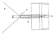
図面において、図1は2つの赤外線送信機を備える固定ステーションの側面を概略的に示し、図2は当該固定ステーションの平面図を概略的に示し、図3は前記固定ステーションの別の実施形態の平面図を概略的に示し、図4はこの固定ステーションと1つの接近中の移動式ロボットを概略的に示し、図5は円形の移動式ロボットの平面図を概略的に示し、図6は本発明に係るブラシを備えたロボットの吸引ユニット前部及び塵検出システムの断面図を示し、図7は本発明に係るブラシを備えたロボットの側面図を示し、図8は清掃技術を例証する図であり、図9はブラシを備えたロボット真空掃除機の側面図であり、図10は図10のロボットの正面図であり、図11はブラシがブロックされた結果として生じる解放アルゴリズムを図示し、図12aから図12cは障害物とのロボットの衝突位置を決定する方法を図示している。
【0037】
図1及び図2を参照すると、固定ステーションは2つの赤外線ビーム発生器2、3を備えている。この赤外光は数キロサイクル(確率誤差、56kHz)の周波数で変調されている。このステーションは低出力で約5φの狭いビームを出射する赤外線送信機2と、高出力で可能な限り無指向性の広いビームを出力する赤外線送信機3とを備えている。
送信機3は、移動式機械装置がその下で自由な位置をとれるように配置されており、その回転の中心はビーム3′の光源に向き合えるようにされ。したがって、この送信機は再充填(供給)ステーションの基部又はロボットの受け入れ用の板に張り出したアーム4の終端部に配置することができる。
【0038】
図3に図示される別の実施形態によれば、ビーム3′の光源は、光源3b及び3cからの2つのビームの交差点によって得られる1つの仮想的光源3aとすることもできる。
この固定ステーションは、その機能に必要な様々な要素を備えており、例えば、コンタクト5を備えたバッテリーを再充電するためのシステム及び真空掃除機のための排出出口6を備えている。
【0039】
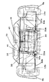
図4及び図5に概略的に図示される移動性ロボット7は、1又は幾つかの再充電可能なバッテリーを備えたロボット真空掃除機(自動化された真空掃除機)である。このロボットは本質的に円形であり、2つの駆動輪8を備え、特にその中心軸の回りに回転する。
【0040】
本体90の側面補強用の円形リングがある。
真空掃除機のタービンの排気口16が円形に並んでいるのが示されている。また、モータ12a、12b双方によって動作する2つの駆動輪8a、8bと、吸気口(図示せず)の近くにある小さな遊動輪キャスター13が示されている。
この機械装置は、少なくとも1つの指向性のある赤外線センサ10、好ましくは2つ(10a、10b)を回転の中心に備えており、後者のケースにおいては、好ましくはこれらの間に、これらの検出角度に等しい角度を成している。この1又は幾つかのセンサは、移動性機械装置の前進移動の方向に向いている。
【0041】
異なる方向、好ましくは後方に向けられた付加的センサ11a、11bは、かかる装置を有利に完成させる。
この又はこれらの付加的センサの配置場所は、この機械装置の回転の中心又はその近傍である必要はない。様々なセンサからの信号は、増幅され、フィルターがかけられ、A/D変換器を介して、この機械装置の移動を制御するマイクロプロセッサに入力される。検出感度(指向性)の範囲は、点線によって図示される。
【0042】
この信号は可能な限り多重化され、すなわち、このロボット内で運搬されているマイクロコンピュータによって連続的に解析され、それぞれの信号は順番に電子スイッチを使用して増幅及び変換の回路列に接続される。
強出力3′である赤外線ビームは、この機械装置が移動する場所の一部をカバーする。このビームの経路上に障害物がない場合には直接的に、ある場合には反射又は回折によって間接的に、このビームは上記カバーを行うことができる。これは、当該赤外光が光源から直接臨むものではなくても上記場所の一部を通過することを可能にする。
【0043】
複数の広く高出力なビームを用いれば、複数のドアによって連通した複数の部屋を全てカバーすることができる。非常に複雑な環境においては、複数の反射鏡又は中継器さえ配置することは、加えて、有用である。
この移動性機械装置は本質的にはランダムな方法で移動し、光源から直接又は反射して到達する赤外線信号を2つのセンサのうちの1つが検出する瞬間はいつも移動している。
【0044】
しかる後、マイクロコンピュータは、周知の方法で、2つの前面側のセンサーl0a及びl0bに同じ信号を、後部において最小の信号を得るために(3以上の検出器、11a、11bを使用する場合)、この機械装置の回転を制御する。
しかる後、マイクロコンピュータは、この機械装置を信号の源、すなわち、固定ステーション1に向かって進行させる。
この「帰投(homing)」の技術の後者の概要自体は知られている。
【0045】
ある瞬間、信号が反射してきた場合、反射地点に移動している当該機械装置は、送信機2(図1〜4参照)によって出射された直接ビームに、又は、もともと検知されているのよりも少ない反射の度合いの放射に遭遇する。
しかる後、この機械装置は前面側の検出器10a、10bの出力のバランスをとり、源流の信号へ向けて自動的に回転する。
【0046】
固定ステーションの近くに到着すると、この移動式機械装置7は、回転の中心に配置された複数のセンサ(前面側のセンサ10a、10b)が、ビーム3の源の近傍に一致する位置に移動する。
その接近は幾つかの方向からなされ、その位置は多分、コネクター5、5′を介した充電器との電気的接続を行うには、或いは他のオペレーションをおこなうには適切ではない。この時点において、狭い低出力のビーム2′がその役割を果たす。
【0047】
発生器3のレベルに到着すると、検出器10a、10bによって収集した信号がかなり減少し、狭いビーム2′から来る信号よりも明らかに弱くなる。確かに、これらのセンサは無指向性ではなく、特に、移動表面に対して垂直な方向の赤外線信号を有効に検出しない。
機械装置7は従ってビーム2′にこれらのセンサを整列させ、固定ステーション上に完全に位置するように再度、発進を始め、そして例えばバッテリーを再充電するためにコネクター5、5′を介して物理的電気接続ができるように、自身を軸として回転する。
【0048】
この発明の他の概要は図7から図8に示される。
図6は車台35の要素によって支持されるロボットの吸引ユニット前部の断面図であり、これは図4及び図5の変形である。このロボットは軸26の回りを回転する複数のブラシ25からなるブラシローラ24を備えている。
【0049】
図7は、吸引のためのタービン20、駆動輪21、フィルター23、送信機27によって覆われた円形領域29を示しており、この領域は検出器28の中心に配置されており、同図には赤外線検出器10a、10bが示される。
図7における矢印はロボット真空掃除機における空気の経路を示す。
本発明の実施形態に係る塵検出のための特定の装置は、移動式ロボット内に設けられ、2つの部分を備えている。
【0050】
- 一方に1つの赤外線送信要素27があり、これと赤外線検出要素28から構成される塵の分析器。これら2つの要素は吸引口29の一方及び他方の側に配置されており、これら相互の軸に沿って位置している。塵が吸引されたり回転ブラシローラー24によって突き出された場合、送信要素と検出要素との間の経路において光の回折27′が生じ、検出要素28の出力において信号変化が生じる。
信号変化の大きさは、塵粒子の大きさ、毎秒ビームを通過する塵粒子の数に略比例する。
この信号は、対数増幅器による増幅の後、機械装置を制御しているマイクロコンピュータによって分析される。
当該受信機におけるビームの平均強度の値もマイクロコンピュータに同じく伝達される。
【0051】
一方、マイクロコンピュータはプログラムによって関連づけられ、前述の解析する装置(解析装置)によって伝達されたデータに従って動作する。
この動作モードにおける、本機械装置の動作について、以下記載する。
この機械装置が清掃のために表面上を移動する場合、塵検出器から出力される信号は定常的にマイクロコンピュータによって分析される。
後者は機械装置を、例えば以下の方法で稼働させる。
【0052】
- 汚れた表面が小さい場合(1cmよりも小さい、距離上の粒子の検出)、この機械装置は、当該領域内における清掃時間を増加させるように、その速度を減少する。この速度変化は検出される粒子の頻度及び寸法にもまた関連する。
- 汚れた表面がより重要な場合(例えば1cmから5cmの間の、距離における粒子の検出)、この機械装置は検出される塵が無くなるまで前進及び後退移動を実行する。しかる後、本機械装置は前進移動を再開する。
- 最終的な汚れた表明が十分に重要な場合(例えば5cmよりも大きい)、この機械装置は、図8に記載されるような1つの組織的な清掃モードに戻る。
図8においては、距離Dは機械装置7の有効な吸引の幅である。
【0053】
この機械装置は、上記マイクロコンピュータによって誘導され、汚れた場所30の全体の長さを決定するために外に向かってスタートして戻ってくる。この装置は、スタート位置31に一度戻ってくると、当該場所の長さに依存する角度αの右側への回転を実行する。この機械装置は、場所30の端まで進行し、右側への新たな回転を実行するため、そのスタート位置31に戻ってくる。上記場所の右側部分が清掃される(検出される粒子が無くなる)まで実行される。この機械装置は、右側に向けて実行された区分の合計に等しい1つの角度だけ左に向きをかえながら上記場所における軸の方角を再びとり、中心から始まる同一の筋書きの動作を左に向けて反復する。
【0054】
左に粒子が無くなった場合、この機械装置は中心31に戻り、その通常動作を再開する。
組織的な清掃の他のアルゴリズムは、好適性は少ないが採用することはできる(螺旋状の経路など)。
汚れのレベルが他の部屋に対して大きく異なっている場合には、前述のような組織的な清掃プロセスを開始することは、その時の汚れのレベルが部屋の平均レベルよりもかなり高い場合のみ重要である。これは、長距離を進行した場合の当該塵検出器によって検出された塵のレベルの全体平均を記憶することによって実現される。
【0055】
塵検出のための配置構成は、速い埃の蓄積を妨げるために、真空清浄化された空気又は塵のない空気の流れを上記検出器及び/又は送信機27、28に向けるように組み立てられる。
この流れは、例えば、上記検出器及び/又は送信機の下に配置された排気口における壁の開口内に設けられた複数の通路32によって引き込まれる。あるいは、好適性は低いが、この空気の流れはタービンを出る空気の幾つかを逸らすダクトによって引き込まれる。
【0056】
しかしながら汚れの蓄積は生じてしまい、受信信号の大きさが低下する。この汚れの蓄積は、検出器から出力される第2の信号(上記ビームの平均強度)により、マイクロコンピュータによって検出される。
このマイクロコンピュータは、上記読み込まれたデータを自動的に補正することによって、この汚れの蓄積を考慮することができ、あるいは、上記受信機の平均の明るさを一定に保持するように上記赤外線送信機を動作させることができる。
【0057】
図9及び図10は、本発明の別の実施形態に係るブラシローラ及び塵検出部を有する自動化された真空掃除機の構成要素を示している。
吸気口29の塵及び空気を吸引するためのモータ41に係合したタービン20が示されている。また、第1フィルタ23a、より目の細かい第2フィルタ23b、駆動輪8a、8b、これに噛合したモータ12a、12b、一対のキャスター13、ブラシローラ24のためのモータ48、塵の収容器42、本体91上の前側赤外線検出器10及び停止部91が示されている。また、マイクロプロセッサ44を支持する集積回路ボード43が示されている。図10においては、モータ12a、12bのための関節のある支持部材52、52a、2つのアーム(軸51a、51bを有する)を有するサスペンションスプリング50a、50bがより詳細に示されている。
【0058】
図11は、本発明に係るアルゴリズムの一例を図示しており、このアルゴリズムは当該ロボットのブラシローラがブロックされた場合に動作する。
【0059】
図12aから図12cは、当該ロボットの障害物との衝突位置を検出するための配置を示している。
図12aは横方向断面、図12bは縦方向断面、図12cはロボット7(ケース60は図示せず)の周囲における要素61、62を示す。
【0060】
ロボットのベース部は、本質的に移動平面内において、中空の直線状絶縁要素60によって囲まれている。この要素60は、ロボットに対して、内側の外部に接着剤63を介して作られ、内部及び縦方向(長手方向)に、可撓性の、直線状抵抗要素61を含んでいる。この要素は、導電性ゴムから構成される抵抗要素である。この抵抗要素の両端には5Vの電位差が印加される。この抵抗要素61の反対に、接合によって同様に60に取り付けられた金属伝導体要素62が設けられている。
【0061】
要素60が障害物65に衝突すると、抵抗要素61と伝導体要素62が弾性的(復元力が働くように)に接触する。この伝導体の張力を測定すると、距離Dを決定することができ、したがって、衝突(接触)位置を推定することができる。
この衝突位置検出の技術は移動性ロボットの分野に広く適用されている。ある特定の適用をするために、異なる平面内において幾つかの要素60を想起することもできる。
【0062】
本発明は、専門家が分離しては結合して適当に理解できる、本明細書において開示された如何なる新規な要素についても参照する。
【図面の簡単な説明】
【図1】 2つの赤外線送信機を備える固定ステーションの側面を概略的に示す。
【図2】 固定ステーションの平面図を概略的に示す。
【図3】 固定ステーションの別の実施形態の平面図を概略的に示す。
【図4】 固定ステーションと1つの接近中の移動式ロボットを概略的に示す。
【図5】 円形の移動式ロボットの平面図を概略的に示す。
【図6】 本発明に係るブラシを備えたロボットの吸引ユニット前部及び塵検出システムの断面図を示す。
【図7】 本発明に係るブラシを備えたロボットの側面図を示す。
【図8】 清掃技術を例証する図である。
【図9】 ブラシを備えたロボット真空掃除機の側面図である。
【図10】 ロボットの正面図である。
【図11】 ブラシがブロックされた結果として生じる解放アルゴリズムを示す。
【図12a】 障害物とのロボットの衝突位置を決定する方法を示す。
【図12b】 障害物とのロボットの衝突位置を決定する方法を示す。
【図12c】 障害物とのロボットの衝突位置を決定する方法を示す。[0001]
The present invention relates to a robot that moves independently (self-running robot, autonomous mobile robot), preferably a cleaning robot, and guides the robot towards a fixed station and / or acts on the local degree of dirt. The present invention relates to a robot control system which can be applied and / or provided with a rotating brush to release the robot after the block of brushes.
[0002]
The present invention relates in particular to a guidance system for autonomous mobile robot trajectories, which is a position control (positioning) for re-supplying energy or approaching a stationary station for releasing the elements collected by the robot. )including. This robot is often, but not limited to, a ground cleaning robot, such as an automated vacuum cleaner (robot vacuum cleaner) with a rechargeable battery. . However, this robot may be a robot for spraying a substance or a monitoring robot.
[0003]
The self-supporting mobile robot includes, for example, a plurality of batteries, and performs a limited self-supporting operation. For continuous operation, the battery must be recharged at regular time intervals. Also, for example, regularly in a fixed position for discharging dust bags (robot-type vacuum cleaner), resupplying fuel (heat engine), or putting product to be sprayed. Other functions that approach are also required.
[0004]
A solution to this problem has already been disclosed (see European Patent Publication No. 07744093), and this machine is sensitive to electromagnetic field gradients and automatically creates a bobbin vertical line that moves laterally by alternating current. Realignment.
In the case of surfaces with elements that interfere with the electromagnetic field (for example, iron reinforced concrete), the above-described system operation becomes difficult.
Thus, in connection with a fixed station, it is preferable that an infrared radiation source (transmitting LED) can be located remotely from the mobile machine.
U.S. Pat. No. 4,679,152 discloses a self-supporting mobile robot. The robot automatically returns to the charging station when the battery charge level falls below a predetermined threshold. The recharging station and mobile robot have an infrared beam transmitter and a detector connected to a microcomputer. The robot and recharging station can therefore perform two-way communication. A search program is used with a photoacoustic system with random movement of the robot on the work surface. Such a system is complex and may not be very effective when it is required to perform very accurate robot alignment with the recharging station for recharging operations.
[0005]
The object of the present invention is, according to the simplest of the embodiments, to provide a system using a narrow beam emanating from a recharging station, which can be detected by a directional detector arranged on the chassis at the center of rotation of the robot. By using it, this drawback is eliminated.
According to a first overview of the invention, a relatively narrow beam, e.g., varying between 2 and 10 and preferably about 5 is delivered from a fixed station. The transmitter sending it and the station associated therewith is preferably oriented so that the beam extends beyond the maximum length of the work surface of the robot. The mobile robot is equipped with a system for detecting the direction of infrared radiation, moves substantially randomly, intersects and detects the narrow beam in a statistically periodic manner.
[0006]
According to a preferred embodiment of the invention, for a certain duration of work, e.g. 15 to 45 minutes, whatever the state of charge of the battery, the robot will cycle the resupply as soon as it crosses the infrared beam of a given intensity. Return towards the fixed station for. If the robot is in the vicinity of the station after the above working time, it will join the station and begin resupply. This process can avoid searching for the beam if the battery condition drops below a predetermined level. The narrow beam allows for precise final alignment with respect to the stationary station, so that recharging can be performed, for example, by electromagnetic induction or, more simply, physical contact with the conductor.
[0007]
As the working time increases, the microprocessor algorithm operates such that the threshold of the intensity of the infrared beam detected by the mobile robot decreases linearly or segment-wise to initiate the return process.
This return process can cease all functions of the robot, but this is essentially unrelated to looking for a resupply station.
[0008]
According to another aspect of the invention, the guidance and alignment system is based on at least two beams with different directivities transmitted from the fixed station, with less directional beams approaching the fixed station. While the beam with higher directivity is used for the final step of accurately aligning the robot with respect to this fixed station. With this alternative, the robot can be guided in a more complex environment (eg an apartment with several doors and several doors).
[0009]
The beam transmitter with the lower directivity is positioned at a fixed fixed station level so that its influence is reduced at the final stage of robot approach and alignment. The transmitter is directional as desired and is located at the end of the arm protruding above the front of the fixed station.
[0010]
In the alignment phase, therefore, the transmitter is advantageously located above the robot, so that the emitted beam will deviate from the detection plane of the robot's detector. The latter is then based on the signal itself of a highly directional transmitter located in the detection plane of the robot's detectors, while re-feeding, for example physical contact, by its rotational movement around its center. You are ready to determine the final alignment. The outputs of these beams are different, and the most powerful beam is not necessarily, but is generally at least a directional beam.
[0011]
This robot includes a directional system for detecting infrared radiation, for example, the strength of the signal is compared by known techniques by a microcomputer to control the rotation towards the source of radiation. For at least two detectors. These detectors are preferentially positioned on the chassis in the center of the robot and are oriented in the direction of movement of the robot. If possible, for example, one or several other detectors may be provided on the lateral or rear side, and the directional direction substantially opposite to the directional direction of the central detector. It is advantageous to have a system with Furthermore, the beam recognized by the robot detector is advantageously modulated in order to avoid background noise.
[0012]
In accordance with this overview of the present invention, a system for aligning the location and location of a stationary station for an autonomous mobile robot moving in a room has been proposed, which is primarily in the plane of a plurality of rooms. In which two modulated infrared beams are emitted, one of which is somewhat more directional than the other. Minimal directional transmitter beams allow positioning and access to the solid station by a mobile robot with direction detectors sensitive to these beams.
[0013]
The signals of the multiple detectors are handled by a single microcomputer that controls the movement of the mobile robot, and the weaker directional transmitter is connected to the desired position in the fixed station when the rear part is coupled. , Located at a fixed station that is perpendicular to the mobile robot, so that a higher directional beam can be detected with higher sensitivity by the aforementioned detectors, this narrow beam Accurate alignment is achieved by rotation of the mechanical device about the vertical axis according to an algorithm based on detection.
[0014]
In another invention, a system for direction sensing and alignment in a stationary station for a self-supporting mobile robot moving in a room is proposed, in which the stationary station comprises at least 3 Emits one modulated infrared beam, one of which is somewhat more directional than the other two, with minimal directivity, typically a transmitter of a higher intensity beam Thus, the mobile robot carrying a plurality of directional detectors having directivity sensitivity to the plurality of already known beams can approach the fixed station. The signals of the plurality of detectors are handled by a single microcomputer that controls the progress of the mobile robot, and a transmitter with low directivity is used so that the beams cross each other in the immediate vicinity of the station. Oriented and located within the fixed station. The most directional beam can also be reduced in intensity, but this can therefore be detected more easily by a plurality of the detectors, around the vertical axis according to an algorithm based on narrow beam detection. Accurate alignment is performed by rotating the mechanical device.
[0015]
According to yet another embodiment, the modulation of the beam emitted by a fixed station, including a microcomputer, can therefore be applied to said robot or to another robot when several robots are used with the same central station. It is also possible to transmit information.
This information can be used for a station for recharging operation and / or discharging (release), or constitutes information on the working method, or stopping or recalling of the robot, sound localization of the robot, etc. can do.
The present invention is also related to guidance technology for vacuum cleaning of dusty ground, and can be applied to a self-supporting robot used for cleaning.
[0016]
EP-A-0769923 is a mobile free standing machine for vacuum cleaning on the ground, low power and small size, for example, which can easily cover surfaces obstructed by furniture parts Is disclosed.
Recharging the robot's battery is advantageous because it is associated with the release of accumulated dust.
The contents of the aforementioned documents are incorporated herein by reference.
[0017]
However, because this suction robot has a low output, it is not always possible to perform a complete cleaning in just one path.
Thus, if there is a machine on a particular dirty surface, it is necessary to assume a longer time for passage (eg, passing from a speed of 20 cm / sec to 10 cm / sec) and / or It is necessary to have an additional path to clean the surface completely.
At the end of this, according to another overview of the present invention, specific cleaning techniques are provided, and such techniques can be applied to any self-supporting robot used for vacuum cleaning and / or brushing.
[0018]
The guidance technique for ground cleaning by this robotic vacuum cleaner certainly does depend on the amount of particles on the surface to be cleaned, the amount of the path followed by the robot, which is close to the suction port of the robot, or Evaluated by a particle analyzer located in one brushing cavity of the robot, which sends a signal to a microcomputer carried by the mobile robot and controls the movement of the robot according to the signal Is certainly a feature.
[0019]
Furthermore, the particle analyzer described above can also have the function of determining the degree of fullness of the dust tank. If the dust accumulates beyond a certain position, ie at the level of the tank located before the filter, the same infrared beam located after the suction port is stopped and the microcomputer determines this as a corresponding signal. To do.
Depending on the measured amount of rising dust, the microcomputer can control, for example, one deceleration and / or linear forward and backward movement of the mobile robot.
[0020]
The microcomputer can also control organized cleaning movements, for example, forward and backward movement in a fan-like sequence.
Advantageously, the microcomputer can take into account the size and number of particles depending on the magnitude (amplitude) and frequency (frequency) of the signal output by the particle analyzer. Analyzing the type of dust collected, thanks to knowing the size and number of particles, refines the robot's behavior by correcting its path, brush speed, and / or vacuum cleaner turbine output can do.
[0021]
This dust analyzer comprises, for example, a transmitter and a receiver, preferably an infrared receiver.
This microcomputer advantageously stores the overall average of the dust levels detected by the dust detector over long distances, and the activation of a particular cleaning algorithm advantageously takes into account the average.
Furthermore, the suction robot includes a dust detector, and one or several elements are automatically cleaned periodically or regularly by a flow of air directed towards its surface.
[0022]
According to another aspect of the invention, the self-supporting robot is a robot that includes a rotating brush.
The present invention proposes a surface cleaning robot provided with a cleaning element, at least a rotating brush, which comprises at least a microcomputer for controlling the speed and / or path of the robot according to an algorithm. Is related to an algorithm that considers at least the rotational speed of the rotating brush to determine the speed and / or the path. This cleaning robot is typically a robot vacuum cleaner.
[0023]
The microcomputer of this robot vacuum cleaner is advantageous because it considers the rotational speed of the rotary brush described above in order to determine the suction force. This suction force can depend, inter alia, on the brush rotational speed described above.
This microcomputer can therefore take into account measuring the rotational speed of the engine (engine) in order to determine the operation of the robot.
However, the presence of a rotating brush has the disadvantage that, for example, when the carpet edge is located on the surface to be cleaned, it sees its own brush block (rotation suppression).
[0024]
A solution having this problem is described in patent application PCT WO 97/40734, which consists in reversing the direction of rotation of the brush so as to release the brush.
The advantage of the solution of the present application is that precise brush control and reversal of the method of rotation are not required. This simplifies robot design. This simpler solution seemed to be more effective in practice.
The device according to the invention comprises a system comprising a rotating brush driven by an engine (engine), which is activated by a microcontroller (or microcomputer) that controls all functions of the autonomous robot. In this regard, reference is made to patent application PCT WO 96/01072 here.
[0025]
The number of rotations of the brush is preferably analyzed constantly by a microcontroller.
This measurement can be carried out by several known techniques (measurement of current consumption in the case of DC motors, impulse frequency measurement in the case of engines without brushes, optical coder).
By measuring this number of revolutions, the microcontroller estimates some information regarding the nature of the cleaned surface or the occurrence of the event and, as a result, applies it to the movement of the robot.
[0026]
For example, when an event such as stopping a rotating brush occurs by hoisting a carpet cover around the brush axis, the microcomputer disconnects the brush and allows the robot to initiate a series of actions for release. I will.
According to the design of the robot, this operation can be one mechanical release, but it is preferable to electrically disconnect the engine (the engine that becomes the driving force).
As an example, some particularly efficient techniques are described below.
[0027]
The robot is retracted by a distance equal to its diameter (the brush is disconnected (uncontrolled)). As a result, the thigh attempts to unfold on the axis of the freely rotating brush.
The brush is released. By retreating, the robot will be outside the bush area. Thereafter, the robot rotates with the brush connected again (control start). At this stage, if the brush is still blocked, it stops its rotational movement and the robot retreats again to allow the brush to rotate, etc. until the brush is released.
The maximum number of iterations is fixed by the maximum free distance and program for robot retreat.
[0028]
If this maximum distance is reached without brush release, the robot will repeat itself with forward movement.
If unsuccessful in releasing the brush, the robot waits in a signal-related state and requires manual intervention.
It is also useful to know the nature of the cleaned ground by analyzing the number of rotations of the brush.
When the rotation speed is high, the surface is smooth, and when the (rotation) speed is low, the surface is covered with carpet. The slower the speed, the thicker the carpet. This analysis allows the robot to adapt the forward speed and suction force to the ground being cleaned.
[0029]
The present invention can be applied to a cleaning robot other than a vacuum cleaner, for example, a robot for cleaning an unspecified surface having a liquid, or a robot for applying wax to a parquet floor. it can.
The present invention can thus be applied to a cleaning robot, the robot comprising a rotating brush and a microcomputer, one means for detecting the rotating brush block associated with the microcomputer; It comprises a robot release algorithm and means for releasing the rotating brush to the associated motor, which causes the robot to move backward and to resume the robot's forward movement according to the rotation.
[0030]
The means for releasing is advantageous in that the engine (engine) is disconnected from the power source.
In short, a robot for cleaning a surface according to one overview of the invention comprises at least a rotating brush, wherein the speed and / or the path and / or the suction force of the possible turbine is the aforementioned rotation. Depends on brush rotation speed.
For robotic vacuum cleaners, particularly for home use, the rotational movement of the brush occurs in a plane perpendicular to the surface to be cleaned.
[0031]
The present invention also relates to an operation method of the cleaning robot described above, wherein the block of the rotating brush is detected by the microcomputer described above, and the microcomputer controls the operation for releasing the robot. The aforementioned releasing operation comprises at least a releasing step of the rotating brush with respect to a motor for driving the rotating brush, and is coupled to one retreat movement of the robot as the rotation and the robot advance again.
This operation may alternatively include several cycles of release-retract-rotate-forward movement.
[0032]
According to another overview of the present invention, this can be applied to any autonomous mobile robot, and more usefully to a robot with large dimensions (probability error: 80 to 250 cm), which robot is in a moving plane. A linear collision sensor that surrounds all or part of the base of the careenage. The sensor is made of a metallic linear conductor and a linear plastic conductor element made in parallel with it, for example made of conductive rubber.
[0033]
The unit is contained within a sheath (case) or insulating flexible member secured along the edge of the body. For example, the linear element is secured by adhesive to two opposite surfaces inside the sheath. These two elements are separated by a small distance. For example, a potential difference of 5 V, that is, 0 V at one end and 5 V at the other end is applied to both ends of the conductive plastic. When a robot collides with an obstacle on the side or front side, one of the two elements can elastically contact the other element under the influence of temporary pressure resulting from the collision between the robot and the obstacle It is. The instantaneous voltage on the conductor element is a function of the distance between one end of the conductive plastic having a high resistance and the point of impact (contact).
[0034]
If a voltage of 2.5V is measured, it indicates that a collision has occurred in the center of the sensor. At the level of the conductive element, the measured voltage thus constitutes a signal that is sent to the microcomputer to identify the location of the collision based on the carry.
The improvements according to the invention can be applied more particularly to mobile robots that move randomly without any system of precise positioning in their normal operating mode.
[0035]
The various aspects of the present invention will be further understood by the following additional description, the accompanying drawings provided by way of example only, but are not limited to the scope of the additional description. Each described feature may be taken separately and generalized according to expert knowledge.
[0036]
The same reference numerals in the drawings indicate the same and equivalent elements.
In the drawings, FIG. 1 schematically shows a side view of a fixed station with two infrared transmitters, FIG. 2 schematically shows a plan view of the fixed station, and FIG. 3 shows another embodiment of the fixed station. FIG. 4 schematically shows the fixed station and one approaching mobile robot, FIG. 5 schematically shows a plan view of the circular mobile robot, and FIG. FIG. 7 shows a sectional view of a suction unit front of a robot with a brush according to the invention and a dust detection system, FIG. 7 shows a side view of a robot with a brush according to the invention, and FIG. 8 illustrates a cleaning technique. 9 is a side view of a robot vacuum cleaner with a brush, FIG. 10 is a front view of the robot of FIG. 10, and FIG. 11 illustrates the release algorithm that results from the brush being blocked. Figure 12c illustrates a method for determining the collision position of the robot with the obstacle from Figure 12a.
[0037]
With reference to FIGS. 1 and 2, the stationary station comprises two
The
[0038]
According to another embodiment illustrated in FIG. 3, the light source of the
This fixing station comprises various elements necessary for its function, for example, a system for recharging a battery with
[0039]
The
[0040]
There is a circular ring for side reinforcement of the
It is shown that the
This mechanical device comprises at least one directional
[0041]
Additional sensors 11a, 11b oriented in different directions, preferably rearward, advantageously complete such a device.
The location of this or these additional sensors need not be at or near the center of rotation of the machine. The signals from the various sensors are amplified, filtered and input via an A / D converter to a microprocessor that controls the movement of this mechanical device. The range of detection sensitivity (directivity) is illustrated by a dotted line.
[0042]
This signal is multiplexed as much as possible, i.e. continuously analyzed by a microcomputer carried in the robot, and each signal is connected in turn to the amplification and conversion circuitry using electronic switches. The
An infrared beam with a strong output 3 'covers a part of the place where the machine moves. The beam can cover the beam directly if there are no obstructions in the beam path, or in some cases indirectly by reflection or diffraction. This allows the infrared light to pass through a portion of the location even if it is not directly facing the light source.
[0043]
If a plurality of wide and high-power beams are used, a plurality of rooms connected by a plurality of doors can be covered. In very complex environments it is additionally useful to arrange a plurality of reflectors or even repeaters.
This mobile machine moves in an essentially random manner and always moves at the moment when one of the two sensors detects an infrared signal that arrives directly or reflected from the light source.
[0044]
Thereafter, the microcomputer, in a well-known manner, obtains the same signal for the two front side sensors l0a and l0b and the minimum signal at the rear (when using three or more detectors, 11a, 11b). , Control the rotation of this mechanical device.
Thereafter, the microcomputer advances the machine towards the source of signals, ie the
The latter outline itself of this “homing” technique is known per se.
[0045]
If the signal is reflected at a certain moment, the mechanical device moving to the reflection point is not directly detected by the direct beam emitted by the transmitter 2 (see FIGS. 1 to 4) or originally. Encounter radiation with a low degree of reflection.
Thereafter, the mechanical device balances the outputs of the front-
[0046]
When arriving near the fixed station, the mobile
The approach is made in several directions, and the position is probably not suitable for making an electrical connection with the charger via
[0047]
When arriving at the level of the
The
[0048]
Another outline of the present invention is shown in FIGS.
FIG. 6 is a cross-sectional view of the front of the suction unit of the robot supported by the elements of the
[0049]
FIG. 7 shows a
The arrows in FIG. 7 indicate air paths in the robot vacuum cleaner.
A specific device for dust detection according to an embodiment of the present invention is provided in a mobile robot and comprises two parts.
[0050]
-A dust analyzer comprising one
The magnitude of the signal change is approximately proportional to the size of the dust particles and the number of dust particles passing through the beam per second.
This signal is analyzed by a microcomputer controlling the mechanical device after amplification by a logarithmic amplifier.
The value of the average intensity of the beam at the receiver is also transmitted to the microcomputer.
[0051]
On the other hand, the microcomputer is related by a program and operates according to data transmitted by the above-described analyzing device (analyzing device).
The operation of the machine device in this operation mode will be described below.
As the machine moves over the surface for cleaning, the signal output from the dust detector is constantly analyzed by the microcomputer.
The latter operates the machine device, for example, in the following manner.
[0052]
-If the soiled surface is small (detection of particles over distance, smaller than 1 cm), the machine will reduce its speed so as to increase the cleaning time in the area. This change in velocity is also related to the frequency and size of the detected particles.
-If a dirty surface is more important (eg detection of particles at a distance between 1 cm and 5 cm), the machine performs forward and backward movement until no dust is detected. Thereafter, the mechanical apparatus resumes forward movement.
-If the final dirty statement is important enough (eg greater than 5 cm), the machine will return to one organized cleaning mode as described in FIG.
In FIG. 8, the distance D is the effective suction width of the
[0053]
The machine is guided by the microcomputer and starts and returns to the outside to determine the overall length of the
[0054]
If there are no more particles on the left, the machine returns to the
Other algorithms for systematic cleaning are less preferred but can be employed (such as spiral paths).
If the level of dirt is significantly different from other rooms, starting an organized cleaning process as described above is important only if the level of dirt at that time is significantly higher than the average level of the room It is. This is achieved by storing the overall average of the level of dust detected by the dust detector when traveling a long distance.
[0055]
The arrangement for dust detection is assembled to direct a stream of vacuum-cleaned air or dust-free air to the detectors and / or
This flow is drawn, for example, by a plurality of
[0056]
However, accumulation of dirt occurs, and the magnitude of the received signal decreases. This accumulation of dirt is detected by the microcomputer by the second signal (average intensity of the beam) output from the detector.
The microcomputer can take this dirt accumulation into account by automatically correcting the read data, or the infrared transmission to keep the average brightness of the receiver constant. The machine can be operated.
[0057]
9 and 10 show components of an automated vacuum cleaner having a brush roller and a dust detector according to another embodiment of the present invention.
Shown is a
[0058]
FIG. 11 illustrates an example of an algorithm according to the present invention, which operates when the brush roller of the robot is blocked.
[0059]
12a to 12c show arrangements for detecting the collision position of the robot with an obstacle.
FIG. 12a shows a transverse section, FIG. 12b shows a longitudinal section, and FIG. 12c shows the
[0060]
The base of the robot is surrounded by a hollow linear insulating
[0061]
When the
This collision position detection technique is widely applied in the field of mobile robots.
[0062]
The present invention refers to any novel elements disclosed herein that an expert can separate and combine to properly understand.
[Brief description of the drawings]
FIG. 1 schematically shows a side view of a stationary station with two infrared transmitters.
FIG. 2 schematically shows a plan view of a fixed station.
FIG. 3 schematically shows a plan view of another embodiment of a fixed station.
FIG. 4 schematically shows a stationary station and one approaching mobile robot.
FIG. 5 schematically shows a plan view of a circular mobile robot.
FIG. 6 is a sectional view of a suction unit front part of a robot equipped with a brush according to the present invention and a dust detection system.
FIG. 7 shows a side view of a robot provided with a brush according to the present invention.
FIG. 8 is a diagram illustrating a cleaning technique.
FIG. 9 is a side view of a robot vacuum cleaner provided with a brush.
FIG. 10 is a front view of the robot.
FIG. 11 illustrates the release algorithm that results from a brush being blocked.
FIG. 12a shows a method for determining the robot's collision position with an obstacle.
FIG. 12b shows a method for determining the collision position of a robot with an obstacle.
FIG. 12c illustrates a method for determining the robot's collision position with an obstacle.
Claims (7)
前記検出器(10a、10b)の指向性システムは、前記ロボット(7)の回転中心におけるフレーム上に位置し、前記ロボットの移動方向に方向づけられており、固定ステーション(1)における正確な位置合わせが、1又は幾つかのより狭い指向性の赤外線ビーム(2′)の検出に基づくアルゴリズムにしたがう鉛直軸周りの該ロボットの回転によって実行され、前記ロボットを前記固定ステーション(1)へ戻すことを制御することができるアルゴリズムは、バッテリーの充電状態が所定レベルよりも低い場合、又はバッテリーの充電の状態とは独立して、ロボットが特定の閾値よりも高い強度の赤外線放射を検出した場合、又はこの両方の条件が揃った場合に、最小の作業時間後に再充電のために固定ステーション(1)に向かって戻りを開始し、前記閾値は前記作業時間の持続時間の増加に伴って減少することを特徴とする、システム。In a system for guiding and positioning a robot (7) that moves independently with respect to a fixed station (1), at least two infrared beams (with different directivities) emitted from or near the fixed station (1) 2 ', 3'), one or several wider directional infrared beams (3 ') are used to approach towards the fixed station (1) and one or several narrower directional beams An infrared beam (2 ') is used in the final step of accurately positioning the robot with respect to the stationary station (1), and the mobile robot is connected to one microcomputer (44) built into the robot. Comprising a directional system of connected infrared emitting detectors (10a, 10b), the robot randomly moving on a work surface, The microcomputer (44) returns the robot to the fixed station (1) by moving the robot in the direction of emission of one or several wider directional infrared beams (3 '). A system including an algorithm that can be controlled,
The directivity system of the detectors (10a, 10b) is located on the frame at the center of rotation of the robot (7) and is oriented in the direction of movement of the robot, so that accurate alignment at the fixed station (1) Is performed by rotation of the robot about a vertical axis according to an algorithm based on the detection of one or several narrower directional infrared beams (2 ') to return the robot to the stationary station (1) The algorithm that can be controlled is when the state of charge of the battery is lower than a predetermined level, or independent of the state of charge of the battery, if the robot detects infrared radiation with an intensity higher than a certain threshold, or If both of these conditions are met, towards the fixed station (1) for recharging after a minimum working time Start the Ri, the threshold is characterized in that it decreases with increasing duration of the working time, the system.
Applications Claiming Priority (7)
| Application Number | Priority Date | Filing Date | Title |
|---|---|---|---|
| BE9700958 | 1997-11-27 | ||
| BE9700958 | 1997-11-27 | ||
| BE9701046 | 1997-12-22 | ||
| BE9701046 | 1997-12-22 | ||
| BE9800341 | 1998-05-07 | ||
| BE9800341 | 1998-05-07 | ||
| PCT/BE1998/000185 WO1999028800A1 (en) | 1997-11-27 | 1998-11-27 | Improvements to mobile robots and their control system |
Publications (2)
| Publication Number | Publication Date |
|---|---|
| JP2001525567A JP2001525567A (en) | 2001-12-11 |
| JP4458664B2 true JP4458664B2 (en) | 2010-04-28 |
Family
ID=27159864
Family Applications (1)
| Application Number | Title | Priority Date | Filing Date |
|---|---|---|---|
| JP2000523587A Expired - Fee Related JP4458664B2 (en) | 1997-11-27 | 1998-11-27 | Improvement of mobile robot and its control system |
Country Status (11)
| Country | Link |
|---|---|
| US (1) | US6389329B1 (en) |
| EP (2) | EP1172719B1 (en) |
| JP (1) | JP4458664B2 (en) |
| KR (1) | KR20010032583A (en) |
| CN (1) | CN1183427C (en) |
| AT (2) | ATE214495T1 (en) |
| AU (1) | AU1327899A (en) |
| CA (1) | CA2311561C (en) |
| DE (2) | DE69804253T2 (en) |
| ES (1) | ES2172936T3 (en) |
| WO (1) | WO1999028800A1 (en) |
Families Citing this family (347)
| Publication number | Priority date | Publication date | Assignee | Title |
|---|---|---|---|---|
| US6532404B2 (en) * | 1997-11-27 | 2003-03-11 | Colens Andre | Mobile robots and their control system |
| SE523080C2 (en) * | 1998-01-08 | 2004-03-23 | Electrolux Ab | Docking system for self-propelled work tools |
| GB9917232D0 (en) | 1999-07-23 | 1999-09-22 | Notetry Ltd | Method of operating a floor cleaning device |
| US8788092B2 (en) | 2000-01-24 | 2014-07-22 | Irobot Corporation | Obstacle following sensor scheme for a mobile robot |
| US8412377B2 (en) | 2000-01-24 | 2013-04-02 | Irobot Corporation | Obstacle following sensor scheme for a mobile robot |
| US6956348B2 (en) * | 2004-01-28 | 2005-10-18 | Irobot Corporation | Debris sensor for cleaning apparatus |
| US6633150B1 (en) * | 2000-05-02 | 2003-10-14 | Personal Robotics, Inc. | Apparatus and method for improving traction for a mobile robot |
| WO2001082766A2 (en) * | 2000-05-02 | 2001-11-08 | Personal Robotics, Inc. | Autonomous floor mopping apparatus |
| US6690134B1 (en) * | 2001-01-24 | 2004-02-10 | Irobot Corporation | Method and system for robot localization and confinement |
| US6883201B2 (en) | 2002-01-03 | 2005-04-26 | Irobot Corporation | Autonomous floor-cleaning robot |
| US7571511B2 (en) | 2002-01-03 | 2009-08-11 | Irobot Corporation | Autonomous floor-cleaning robot |
| DE50113471D1 (en) * | 2001-01-29 | 2008-02-21 | Wessel Werk Gmbh | Suction head for a vacuum cleaning device |
| DE10110907A1 (en) * | 2001-03-07 | 2002-09-19 | Kaercher Gmbh & Co Alfred | Floor cleaning device |
| US6688936B2 (en) * | 2001-03-28 | 2004-02-10 | Steven Davis | Rotating toy with directional vector control |
| US7255623B2 (en) * | 2001-03-28 | 2007-08-14 | Steven Davis | Self-stabilizing rotating toy |
| AU767561B2 (en) * | 2001-04-18 | 2003-11-13 | Samsung Kwangju Electronics Co., Ltd. | Robot cleaner, system employing the same and method for reconnecting to external recharging device |
| US8396592B2 (en) | 2001-06-12 | 2013-03-12 | Irobot Corporation | Method and system for multi-mode coverage for an autonomous robot |
| EP2287696B1 (en) | 2001-06-12 | 2018-01-10 | iRobot Corporation | Method and system for multi-code coverage for an autonomous robot |
| US7663333B2 (en) | 2001-06-12 | 2010-02-16 | Irobot Corporation | Method and system for multi-mode coverage for an autonomous robot |
| US7155307B2 (en) * | 2001-09-09 | 2006-12-26 | Seemann Henry R | Surface adhering tool carrying robot |
| IL145680A0 (en) * | 2001-09-26 | 2002-06-30 | Friendly Robotics Ltd | Robotic vacuum cleaner |
| WO2003026474A2 (en) * | 2001-09-26 | 2003-04-03 | Friendly Robotics Ltd. | Robotic vacuum cleaner |
| US9128486B2 (en) | 2002-01-24 | 2015-09-08 | Irobot Corporation | Navigational control system for a robotic device |
| SE525499C2 (en) * | 2002-03-12 | 2005-03-01 | Htc Sweden Ab | Device on a mobile machine for grinding floor surfaces |
| US6836701B2 (en) | 2002-05-10 | 2004-12-28 | Royal Appliance Mfg. Co. | Autonomous multi-platform robotic system |
| JP4448024B2 (en) * | 2002-05-31 | 2010-04-07 | 富士通株式会社 | Remote operation robot and robot self-position identification method |
| DE10231386B4 (en) * | 2002-07-08 | 2004-05-06 | Alfred Kärcher Gmbh & Co. Kg | Sensor device and self-propelled floor cleaning device with a sensor device |
| DE10231387A1 (en) * | 2002-07-08 | 2004-02-12 | Alfred Kärcher Gmbh & Co. Kg | Floor cleaning device |
| DE10231391A1 (en) | 2002-07-08 | 2004-02-12 | Alfred Kärcher Gmbh & Co. Kg | Tillage system |
| DE10231384A1 (en) * | 2002-07-08 | 2004-02-05 | Alfred Kärcher Gmbh & Co. Kg | Method for operating a floor cleaning system and floor cleaning system for applying the method |
| DE10231388A1 (en) | 2002-07-08 | 2004-02-05 | Alfred Kärcher Gmbh & Co. Kg | Tillage system |
| US20040162637A1 (en) | 2002-07-25 | 2004-08-19 | Yulun Wang | Medical tele-robotic system with a master remote station with an arbitrator |
| US6925357B2 (en) * | 2002-07-25 | 2005-08-02 | Intouch Health, Inc. | Medical tele-robotic system |
| US20040031111A1 (en) * | 2002-08-14 | 2004-02-19 | Jose Porchia | Disposable dust receptacle |
| US7054716B2 (en) * | 2002-09-06 | 2006-05-30 | Royal Appliance Mfg. Co. | Sentry robot system |
| US8386081B2 (en) | 2002-09-13 | 2013-02-26 | Irobot Corporation | Navigational control system for a robotic device |
| US8428778B2 (en) | 2002-09-13 | 2013-04-23 | Irobot Corporation | Navigational control system for a robotic device |
| KR100468107B1 (en) * | 2002-10-31 | 2005-01-26 | 삼성광주전자 주식회사 | Robot cleaner system having external charging apparatus and method for docking with the same apparatus |
| JP2004237075A (en) * | 2003-02-06 | 2004-08-26 | Samsung Kwangju Electronics Co Ltd | Robot cleaner system provided with external charger and connection method for robot cleaner to external charger |
| US7801645B2 (en) * | 2003-03-14 | 2010-09-21 | Sharper Image Acquisition Llc | Robotic vacuum cleaner with edge and object detection system |
| US20040211444A1 (en) * | 2003-03-14 | 2004-10-28 | Taylor Charles E. | Robot vacuum with particulate detector |
| US20050010331A1 (en) * | 2003-03-14 | 2005-01-13 | Taylor Charles E. | Robot vacuum with floor type modes |
| US7805220B2 (en) | 2003-03-14 | 2010-09-28 | Sharper Image Acquisition Llc | Robot vacuum with internal mapping system |
| KR100492590B1 (en) * | 2003-03-14 | 2005-06-03 | 엘지전자 주식회사 | Auto charge system and return method for robot |
| US20040200505A1 (en) * | 2003-03-14 | 2004-10-14 | Taylor Charles E. | Robot vac with retractable power cord |
| FR2854966B1 (en) * | 2003-05-09 | 2005-12-30 | Wany Robotics | AUTOMATIC ELECTRIC RECHARGEABLE WIRELESS POINTING SYSTEM FOR COMPUTER |
| US7133746B2 (en) * | 2003-07-11 | 2006-11-07 | F Robotics Acquistions, Ltd. | Autonomous machine for docking with a docking station and method for docking |
| KR100548272B1 (en) * | 2003-07-23 | 2006-02-02 | 엘지전자 주식회사 | Position detection apparatus and method for mobile robot |
| CN2637136Y (en) * | 2003-08-11 | 2004-09-01 | 泰怡凯电器(苏州)有限公司 | Self-positioning mechanism for robot |
| US7813836B2 (en) | 2003-12-09 | 2010-10-12 | Intouch Technologies, Inc. | Protocol for a remotely controlled videoconferencing robot |
| DE10357636B4 (en) * | 2003-12-10 | 2013-05-08 | Vorwerk & Co. Interholding Gmbh | Automatically movable floor dust collecting device |
| US20050144194A1 (en) * | 2003-12-24 | 2005-06-30 | Lopez Fernando G. | Object storage |
| US7332890B2 (en) | 2004-01-21 | 2008-02-19 | Irobot Corporation | Autonomous robot auto-docking and energy management systems and methods |
| AU2011204422B2 (en) * | 2004-01-21 | 2012-09-13 | Irobot Corporation | Method of docking an autonomous robot |
| KR20110009270A (en) * | 2004-01-28 | 2011-01-27 | 아이로보트 코퍼레이션 | Debris sensor for cleaning apparatus |
| CN100370938C (en) * | 2004-02-06 | 2008-02-27 | 泰怡凯电器(苏州)有限公司 | Butt-jointing method for automatic vacuum cleaner and charging seat |
| US20060020369A1 (en) * | 2004-03-11 | 2006-01-26 | Taylor Charles E | Robot vacuum cleaner |
| DE102004014273A1 (en) * | 2004-03-22 | 2005-10-13 | BSH Bosch und Siemens Hausgeräte GmbH | Surface machining system |
| WO2005098476A1 (en) | 2004-03-29 | 2005-10-20 | Evolution Robotics, Inc. | Method and apparatus for position estimation using reflected light sources |
| US7617557B2 (en) | 2004-04-02 | 2009-11-17 | Royal Appliance Mfg. Co. | Powered cleaning appliance |
| TWI258259B (en) * | 2004-04-20 | 2006-07-11 | Jason Yan | Automatic charging system of mobile robotic electronic device |
| KR100580301B1 (en) * | 2004-06-22 | 2006-05-16 | 삼성전자주식회사 | Air purifier and control method thereof |
| JP2008508572A (en) | 2004-06-24 | 2008-03-21 | アイロボット コーポレーション | Portable robot programming and diagnostic tools |
| US11209833B2 (en) | 2004-07-07 | 2021-12-28 | Irobot Corporation | Celestial navigation system for an autonomous vehicle |
| US8972052B2 (en) * | 2004-07-07 | 2015-03-03 | Irobot Corporation | Celestial navigation system for an autonomous vehicle |
| US7706917B1 (en) | 2004-07-07 | 2010-04-27 | Irobot Corporation | Celestial navigation system for an autonomous robot |
| US8077963B2 (en) | 2004-07-13 | 2011-12-13 | Yulun Wang | Mobile robot with a head-based movement mapping scheme |
| KR100641113B1 (en) * | 2004-07-30 | 2006-11-02 | 엘지전자 주식회사 | Mobile robot and his moving control method |
| KR100656701B1 (en) * | 2004-10-27 | 2006-12-13 | 삼성광주전자 주식회사 | Robot cleaner system and Method for return to external charge apparatus |
| US7744441B2 (en) * | 2004-11-05 | 2010-06-29 | Mattel, Inc. | Interactive play sets |
| KR20070112106A (en) | 2004-11-23 | 2007-11-22 | 에스.씨. 존슨 앤드 선, 인코포레이티드 | Device and methods of providing air purification in combination with superficial floor cleaning |
| KR100803203B1 (en) * | 2005-02-04 | 2008-02-14 | 삼성전자주식회사 | Apparatus and method for correcting location information of mobile body, and computer-readable recording media storing computer program controlling the apparatus |
| US7389156B2 (en) * | 2005-02-18 | 2008-06-17 | Irobot Corporation | Autonomous surface cleaning robot for wet and dry cleaning |
| US8392021B2 (en) | 2005-02-18 | 2013-03-05 | Irobot Corporation | Autonomous surface cleaning robot for wet cleaning |
| US7620476B2 (en) | 2005-02-18 | 2009-11-17 | Irobot Corporation | Autonomous surface cleaning robot for dry cleaning |
| WO2006089307A2 (en) * | 2005-02-18 | 2006-08-24 | Irobot Corporation | Autonomous surface cleaning robot for wet and dry cleaning |
| US7681839B2 (en) * | 2005-02-25 | 2010-03-23 | Smiths Aerospace Llc | Optical tracking system for refueling |
| US8930023B2 (en) | 2009-11-06 | 2015-01-06 | Irobot Corporation | Localization by learning of wave-signal distributions |
| AT502251B1 (en) * | 2005-05-06 | 2007-12-15 | Puchegger U Beisteiner Parkett | FLOOR SANDERS |
| KR100645814B1 (en) * | 2005-06-07 | 2006-11-23 | 엘지전자 주식회사 | Automatic charging return system of moving robot and method for thereof |
| KR100645381B1 (en) * | 2005-08-31 | 2006-11-14 | 삼성광주전자 주식회사 | Apparatus for return to external charge of robot cleaner and method thereof |
| US9198728B2 (en) | 2005-09-30 | 2015-12-01 | Intouch Technologies, Inc. | Multi-camera mobile teleconferencing platform |
| US9002511B1 (en) | 2005-10-21 | 2015-04-07 | Irobot Corporation | Methods and systems for obstacle detection using structured light |
| KR100692897B1 (en) * | 2005-10-28 | 2007-03-12 | 엘지전자 주식회사 | Moving robot |
| US20070113188A1 (en) * | 2005-11-17 | 2007-05-17 | Bales Christopher E | System and method for providing dynamic content in a communities framework |
| ES2706727T3 (en) | 2005-12-02 | 2019-04-01 | Irobot Corp | Robot system |
| EP2816434A3 (en) | 2005-12-02 | 2015-01-28 | iRobot Corporation | Autonomous coverage robot |
| KR101300493B1 (en) | 2005-12-02 | 2013-09-02 | 아이로보트 코퍼레이션 | Coverage robot mobility |
| US8584305B2 (en) | 2005-12-02 | 2013-11-19 | Irobot Corporation | Modular robot |
| KR101099808B1 (en) | 2005-12-02 | 2011-12-27 | 아이로보트 코퍼레이션 | Robot system |
| WO2007109627A2 (en) | 2006-03-17 | 2007-09-27 | Irobot Corporation | Lawn care robot |
| KR100766439B1 (en) * | 2006-03-29 | 2007-10-12 | 엘지전자 주식회사 | Returning system to charging station for moving robot |
| JP4195894B2 (en) | 2006-03-30 | 2008-12-17 | 株式会社東芝 | Docking system |
| KR20070104989A (en) * | 2006-04-24 | 2007-10-30 | 삼성전자주식회사 | Robot cleaner system and method to eliminate dust thereof |
| TWI303754B (en) * | 2006-05-09 | 2008-12-01 | Ind Tech Res Inst | Obstacle and cliff avoiding system and method thereof |
| ATE523131T1 (en) | 2006-05-19 | 2011-09-15 | Irobot Corp | WASTE REMOVAL FROM CLEANING ROBOTS |
| US8417383B2 (en) | 2006-05-31 | 2013-04-09 | Irobot Corporation | Detecting robot stasis |
| US8849679B2 (en) | 2006-06-15 | 2014-09-30 | Intouch Technologies, Inc. | Remote controlled robot system that provides medical images |
| TWI305610B (en) * | 2006-07-07 | 2009-01-21 | Ind Tech Res Inst | Path guidance method for autonomous mobile device |
| US8010229B2 (en) * | 2006-12-05 | 2011-08-30 | Electronics And Telecommunications Research Institute | Method and apparatus for returning cleaning robot to charge station |
| US8306659B2 (en) | 2006-12-06 | 2012-11-06 | F Robotics Acquisitions Ltd. | Autonomous robot |
| TWI330305B (en) * | 2006-12-28 | 2010-09-11 | Ind Tech Res Inst | Method for routing a robotic apparatus to a service station and robotic apparatus service system using thereof |
| CN101211186B (en) * | 2006-12-29 | 2010-12-08 | 财团法人工业技术研究院 | Method for mobile device returning to service station and mobile device service system |
| DE102007002934A1 (en) * | 2007-01-19 | 2008-07-24 | BSH Bosch und Siemens Hausgeräte GmbH | Method for monitoring charging condition of accumulator for autonomous mobile robot, particularly autonomous window cleaner, which involves measuring static and dynamic behavior of terminal voltage by monitoring circuit |
| KR101414321B1 (en) | 2007-05-09 | 2014-07-01 | 아이로보트 코퍼레이션 | Autonomous coverage robot |
| US9160783B2 (en) | 2007-05-09 | 2015-10-13 | Intouch Technologies, Inc. | Robot system that operates through a network firewall |
| US7627927B2 (en) * | 2007-06-08 | 2009-12-08 | Tacony Corporation | Vacuum cleaner with sensing system |
| JP2009012668A (en) * | 2007-07-06 | 2009-01-22 | Sharp Corp | Controller, and mobile robot system using it |
| DE102007036170B4 (en) | 2007-08-02 | 2012-01-26 | BSH Bosch und Siemens Hausgeräte GmbH | Method and device for determining the amount of dust particles, in particular in a dust-collecting robot, and dust-collecting device with such a device |
| JP4600781B2 (en) * | 2007-09-05 | 2010-12-15 | Necアクセステクニカ株式会社 | Robot charging system |
| US8632376B2 (en) * | 2007-09-20 | 2014-01-21 | Irobot Corporation | Robotic game systems and methods |
| CN101446832B (en) * | 2007-11-27 | 2011-05-18 | 常州新区常工电子计算机有限公司 | Control method of automatic obstacle-avoiding of robot cleaner |
| US20090140926A1 (en) * | 2007-12-04 | 2009-06-04 | Elden Douglas Traster | System and method for localization utilizing dynamically deployable beacons |
| EP2252190B1 (en) * | 2008-01-28 | 2012-05-23 | Seegrid Corporation | Service robot and method of operating same |
| US8892256B2 (en) * | 2008-01-28 | 2014-11-18 | Seegrid Corporation | Methods for real-time and near real-time interactions with robots that service a facility |
| JP5606927B2 (en) * | 2008-01-28 | 2014-10-15 | シーグリッド コーポレーション | Method for repurposing spatio-temporal information collected by service robots |
| US8755936B2 (en) * | 2008-01-28 | 2014-06-17 | Seegrid Corporation | Distributed multi-robot system |
| JP5011145B2 (en) * | 2008-02-04 | 2012-08-29 | 株式会社日立製作所 | Charger for self-propelled vacuum cleaner |
| JP4710058B2 (en) * | 2008-02-20 | 2011-06-29 | Necアクセステクニカ株式会社 | Charger |
| US8915692B2 (en) * | 2008-02-21 | 2014-12-23 | Harvest Automation, Inc. | Adaptable container handling system |
| US10875182B2 (en) | 2008-03-20 | 2020-12-29 | Teladoc Health, Inc. | Remote presence system mounted to operating room hardware |
| US8179418B2 (en) | 2008-04-14 | 2012-05-15 | Intouch Technologies, Inc. | Robotic based health care system |
| US8170241B2 (en) | 2008-04-17 | 2012-05-01 | Intouch Technologies, Inc. | Mobile tele-presence system with a microphone system |
| US9193065B2 (en) | 2008-07-10 | 2015-11-24 | Intouch Technologies, Inc. | Docking system for a tele-presence robot |
| US9842192B2 (en) | 2008-07-11 | 2017-12-12 | Intouch Technologies, Inc. | Tele-presence robot system with multi-cast features |
| US8301325B2 (en) * | 2008-07-28 | 2012-10-30 | Precise Path Robotics, Inc. | System and method for autonomous vehicle localization |
| CN101670580B (en) * | 2008-09-11 | 2011-11-30 | 泰怡凯电器(苏州)有限公司 | Intelligent robot system and barrier-free guidance method and electronic guidance mirrors thereof |
| US8340819B2 (en) | 2008-09-18 | 2012-12-25 | Intouch Technologies, Inc. | Mobile videoconferencing robot system with network adaptive driving |
| CN101375781B (en) * | 2008-09-28 | 2011-11-30 | 泰怡凯电器(苏州)有限公司 | Ground processing system and method for contacting joint of ground processing equipment and charging stand |
| US8996165B2 (en) | 2008-10-21 | 2015-03-31 | Intouch Technologies, Inc. | Telepresence robot with a camera boom |
| US8463435B2 (en) | 2008-11-25 | 2013-06-11 | Intouch Technologies, Inc. | Server connectivity control for tele-presence robot |
| US9138891B2 (en) | 2008-11-25 | 2015-09-22 | Intouch Technologies, Inc. | Server connectivity control for tele-presence robot |
| CN101766915A (en) * | 2008-12-31 | 2010-07-07 | 鸿富锦精密工业(深圳)有限公司 | Electronic toy |
| US8849680B2 (en) | 2009-01-29 | 2014-09-30 | Intouch Technologies, Inc. | Documentation through a remote presence robot |
| CN101502406B (en) * | 2009-02-20 | 2012-05-30 | 泰怡凯电器(苏州)有限公司 | Floor processing system as well as rapid butt-joint method for floor treating device and charging stand |
| CN101822905A (en) * | 2009-03-03 | 2010-09-08 | 鸿富锦精密工业(深圳)有限公司 | Electronic toy |
| CN101524257B (en) * | 2009-03-31 | 2011-06-15 | 杭州五星电子有限公司 | Smart dust collector method for realizing automatic charging |
| US8897920B2 (en) | 2009-04-17 | 2014-11-25 | Intouch Technologies, Inc. | Tele-presence robot system with software modularity, projector and laser pointer |
| US20100292884A1 (en) * | 2009-05-12 | 2010-11-18 | Rogelio Manfred Neumann | Device for Influencing Navigation of an Autonomous Vehicle |
| US8774970B2 (en) | 2009-06-11 | 2014-07-08 | S.C. Johnson & Son, Inc. | Trainable multi-mode floor cleaning device |
| EP2263510B1 (en) * | 2009-06-19 | 2017-09-13 | Samsung Electronics Co., Ltd. | Robot cleaner and method of its travel control |
| USRE47265E1 (en) | 2009-06-30 | 2019-03-05 | Lg Electronics Inc. | Charging device of robot cleaner |
| US8384755B2 (en) | 2009-08-26 | 2013-02-26 | Intouch Technologies, Inc. | Portable remote presence robot |
| US11399153B2 (en) | 2009-08-26 | 2022-07-26 | Teladoc Health, Inc. | Portable telepresence apparatus |
| TWM377001U (en) * | 2009-10-16 | 2010-03-21 | Micro Star Int Co Ltd | Electronic device |
| US9026302B2 (en) | 2009-11-06 | 2015-05-05 | Irobot Corporation | Methods and systems for complete coverage of a surface by an autonomous robot |
| US9310806B2 (en) * | 2010-01-06 | 2016-04-12 | Irobot Corporation | System for localization and obstacle detection using a common receiver |
| US11154981B2 (en) | 2010-02-04 | 2021-10-26 | Teladoc Health, Inc. | Robot user interface for telepresence robot system |
| US8800107B2 (en) | 2010-02-16 | 2014-08-12 | Irobot Corporation | Vacuum brush |
| US8670017B2 (en) | 2010-03-04 | 2014-03-11 | Intouch Technologies, Inc. | Remote presence system including a cart that supports a robot face and an overhead camera |
| CN102811604B (en) * | 2010-03-17 | 2016-03-30 | 胡斯华纳有限公司 | For robotic garden tool being guided to the method and system in precalculated position |
| US10343283B2 (en) | 2010-05-24 | 2019-07-09 | Intouch Technologies, Inc. | Telepresence robot system that can be accessed by a cellular phone |
| US10808882B2 (en) | 2010-05-26 | 2020-10-20 | Intouch Technologies, Inc. | Tele-robotic system with a robot face placed on a chair |
| US9264664B2 (en) | 2010-12-03 | 2016-02-16 | Intouch Technologies, Inc. | Systems and methods for dynamic bandwidth allocation |
| EP2659260B1 (en) | 2010-12-30 | 2019-11-20 | iRobot Corporation | Debris monitoring |
| KR101523980B1 (en) * | 2011-01-18 | 2015-06-01 | 삼성전자 주식회사 | Autonomous cleaning device |
| US9323250B2 (en) | 2011-01-28 | 2016-04-26 | Intouch Technologies, Inc. | Time-dependent navigation of telepresence robots |
| US8718837B2 (en) | 2011-01-28 | 2014-05-06 | Intouch Technologies | Interfacing with a mobile telepresence robot |
| US10769739B2 (en) | 2011-04-25 | 2020-09-08 | Intouch Technologies, Inc. | Systems and methods for management of information among medical providers and facilities |
| ES2723176T3 (en) | 2011-04-29 | 2019-08-22 | Irobot Corp | An autonomous mobile robot |
| US11471020B2 (en) | 2011-04-29 | 2022-10-18 | Irobot Corporation | Robotic vacuum cleaning system |
| US9098611B2 (en) | 2012-11-26 | 2015-08-04 | Intouch Technologies, Inc. | Enhanced video interaction for a user interface of a telepresence network |
| US20140139616A1 (en) | 2012-01-27 | 2014-05-22 | Intouch Technologies, Inc. | Enhanced Diagnostics for a Telepresence Robot |
| US8352114B2 (en) * | 2011-05-20 | 2013-01-08 | VGO Communications, Inc | Method and apparatus for docking a robotic device with a charging station |
| CN102934565B (en) * | 2011-07-16 | 2015-12-09 | 苏州宝时得电动工具有限公司 | Mower and docking charging system |
| US8800101B2 (en) * | 2011-07-25 | 2014-08-12 | Lg Electronics Inc. | Robot cleaner and self testing method of the same |
| ES2692888T3 (en) | 2011-09-07 | 2018-12-05 | Irobot Corporation | SONAR system for an autonomous vehicle |
| GB2494447B (en) * | 2011-09-09 | 2014-02-26 | Dyson Technology Ltd | Autonomous surface treating appliance |
| FR2981970B1 (en) * | 2011-10-27 | 2013-11-29 | Zodiac Pool Care Europe | IMMEREDE SURFACE CLEANER APPARATUS WITH SEMI-AUTOMATIC RETURN CONTROL |
| US9147173B2 (en) | 2011-10-31 | 2015-09-29 | Harvest Automation, Inc. | Methods and systems for automated transportation of items between variable endpoints |
| US8836751B2 (en) | 2011-11-08 | 2014-09-16 | Intouch Technologies, Inc. | Tele-presence system with a user interface that displays different communication links |
| US8937410B2 (en) | 2012-01-17 | 2015-01-20 | Harvest Automation, Inc. | Emergency stop method and system for autonomous mobile robots |
| WO2013107374A1 (en) * | 2012-01-20 | 2013-07-25 | 苏州宝时得电动工具有限公司 | Automatic work apparatus and control method therefor |
| CN103251359B (en) * | 2012-02-16 | 2017-03-08 | 恩斯迈电子(深圳)有限公司 | Control method of sweeping robot |
| EP2825925B1 (en) | 2012-03-15 | 2022-04-27 | iRobot Corporation | Bumper for robot comprising sensor arrays |
| CN103365291B (en) * | 2012-03-29 | 2016-02-17 | 凌海科技企业股份有限公司 | Control module and automatic travelling device is led the method for cradle |
| US9146560B2 (en) | 2012-03-30 | 2015-09-29 | Irobot Corporation | System and method for implementing force field deterrent for robot |
| US9251313B2 (en) | 2012-04-11 | 2016-02-02 | Intouch Technologies, Inc. | Systems and methods for visualizing and managing telepresence devices in healthcare networks |
| US8902278B2 (en) | 2012-04-11 | 2014-12-02 | Intouch Technologies, Inc. | Systems and methods for visualizing and managing telepresence devices in healthcare networks |
| US9361021B2 (en) | 2012-05-22 | 2016-06-07 | Irobot Corporation | Graphical user interfaces including touchpad driving interfaces for telemedicine devices |
| EP2852881A4 (en) | 2012-05-22 | 2016-03-23 | Intouch Technologies Inc | Graphical user interfaces including touchpad driving interfaces for telemedicine devices |
| CN103576678B (en) * | 2012-07-20 | 2016-12-21 | 苏州宝时得电动工具有限公司 | Auto-returned system and the method controlling automatic running device return bus stop |
| CN103565348B (en) * | 2012-07-27 | 2016-05-04 | 科沃斯机器人有限公司 | Intelligent cleaning system |
| ES2610755T3 (en) | 2012-08-27 | 2017-05-03 | Aktiebolaget Electrolux | Robot positioning system |
| EP3287242B1 (en) | 2012-09-21 | 2021-10-20 | iRobot Corporation | Proximity sensor for a mobile robot |
| CN104703460B (en) * | 2012-10-09 | 2018-03-30 | 胡斯华纳有限公司 | For the method and system for the covering distribution for improving automatic garden tool set |
| US8972061B2 (en) | 2012-11-02 | 2015-03-03 | Irobot Corporation | Autonomous coverage robot |
| US9020637B2 (en) | 2012-11-02 | 2015-04-28 | Irobot Corporation | Simultaneous localization and mapping for a mobile robot |
| US9178370B2 (en) | 2012-12-28 | 2015-11-03 | Irobot Corporation | Coverage robot docking station |
| US9483055B2 (en) | 2012-12-28 | 2016-11-01 | Irobot Corporation | Autonomous coverage robot |
| US9282867B2 (en) | 2012-12-28 | 2016-03-15 | Irobot Corporation | Autonomous coverage robot |
| WO2014101840A1 (en) | 2012-12-28 | 2014-07-03 | 苏州宝时得电动工具有限公司 | Auto mowing system |
| US9233472B2 (en) | 2013-01-18 | 2016-01-12 | Irobot Corporation | Mobile robot providing environmental mapping for household environmental control |
| US9375847B2 (en) | 2013-01-18 | 2016-06-28 | Irobot Corporation | Environmental management systems including mobile robots and methods using same |
| AU2013374347B2 (en) | 2013-01-18 | 2016-05-19 | Irobot Corporation | Environmental management systems including mobile robots and methods using same |
| KR101490170B1 (en) * | 2013-03-05 | 2015-02-05 | 엘지전자 주식회사 | Robot cleaner |
| US9326654B2 (en) | 2013-03-15 | 2016-05-03 | Irobot Corporation | Roller brush for surface cleaning robots |
| KR101395888B1 (en) * | 2013-03-21 | 2014-05-27 | 엘지전자 주식회사 | Robot cleaner and operating method |
| JP6198234B2 (en) | 2013-04-15 | 2017-09-20 | アクティエボラゲット エレクトロラックス | Robot vacuum cleaner with protruding side brush |
| US10448794B2 (en) | 2013-04-15 | 2019-10-22 | Aktiebolaget Electrolux | Robotic vacuum cleaner |
| JP5713047B2 (en) * | 2013-04-18 | 2015-05-07 | 株式会社安川電機 | Mobile robot, mobile robot positioning system, and mobile robot positioning method |
| KR101437778B1 (en) | 2013-05-06 | 2014-09-11 | (주)마미로봇 | Guide signal transmitter of docking station |
| JP6072603B2 (en) * | 2013-05-16 | 2017-02-01 | 日立アプライアンス株式会社 | Autonomous traveling vacuum cleaner |
| CN103231367B (en) * | 2013-05-20 | 2016-04-20 | 苏州大学 | A kind of single axial movement controls actual training device and loading and unloading method |
| US9037396B2 (en) | 2013-05-23 | 2015-05-19 | Irobot Corporation | Simultaneous localization and mapping for a mobile robot |
| CN103284664A (en) * | 2013-06-28 | 2013-09-11 | 苏州市牛勿耳关电器科技有限公司 | Intelligent cleaning robot |
| CN104416568B (en) * | 2013-08-20 | 2016-06-22 | 苏州宝时得电动工具有限公司 | The control method of automatic working system and automatic running device |
| KR102095817B1 (en) * | 2013-10-31 | 2020-04-01 | 엘지전자 주식회사 | Mobile robot, charging apparatus for the mobile robot, and mobile robot system |
| KR102093177B1 (en) * | 2013-10-31 | 2020-03-25 | 엘지전자 주식회사 | Moving Robot and operating method |
| US11272822B2 (en) | 2013-11-12 | 2022-03-15 | Irobot Corporation | Mobile floor cleaning robot with pad holder |
| US9233468B2 (en) | 2013-11-12 | 2016-01-12 | Irobot Corporation | Commanding a mobile robot using glyphs |
| CN104622385B (en) * | 2013-11-12 | 2017-03-08 | 沈阳新松机器人自动化股份有限公司 | A kind of crash sensor and intellective dust collector robot |
| US9615712B2 (en) | 2013-11-12 | 2017-04-11 | Irobot Corporation | Mobile floor cleaning robot |
| US9427127B2 (en) | 2013-11-12 | 2016-08-30 | Irobot Corporation | Autonomous surface cleaning robot |
| CN104644061B (en) * | 2013-11-20 | 2017-09-19 | 科沃斯商用机器人有限公司 | Self-movement robot and its antidote with apparatus for correcting |
| JP2017503267A (en) | 2013-12-18 | 2017-01-26 | アイロボット コーポレイション | Autonomous mobile robot |
| KR102137857B1 (en) | 2013-12-19 | 2020-07-24 | 에이비 엘렉트로룩스 | Robotic cleaning device and method for landmark recognition |
| EP3082541B1 (en) | 2013-12-19 | 2018-04-04 | Aktiebolaget Electrolux | Adaptive speed control of rotating side brush |
| KR102393550B1 (en) | 2013-12-19 | 2022-05-04 | 에이비 엘렉트로룩스 | Prioritizing cleaning areas |
| CN105813528B (en) | 2013-12-19 | 2019-05-07 | 伊莱克斯公司 | The barrier sensing of robotic cleaning device is creeped |
| US10209080B2 (en) | 2013-12-19 | 2019-02-19 | Aktiebolaget Electrolux | Robotic cleaning device |
| CN105792721B (en) | 2013-12-19 | 2020-07-21 | 伊莱克斯公司 | Robotic vacuum cleaner with side brush moving in spiral pattern |
| CN105829985B (en) | 2013-12-19 | 2020-04-07 | 伊莱克斯公司 | Robot cleaning device with peripheral recording function |
| WO2015090439A1 (en) | 2013-12-20 | 2015-06-25 | Aktiebolaget Electrolux | Dust container |
| CN105899112B (en) | 2014-01-10 | 2018-07-06 | 艾罗伯特公司 | autonomous mobile robot |
| AU2015241429B2 (en) | 2014-03-31 | 2018-12-06 | Irobot Corporation | Autonomous mobile robot |
| DE102014007624A1 (en) * | 2014-05-23 | 2015-11-26 | Daimler Ag | Method for determining variables influencing the movement of a robot |
| KR102325130B1 (en) | 2014-07-10 | 2021-11-12 | 에이비 엘렉트로룩스 | Method for detecting a measurement error in a robotic cleaning device |
| GB2529846B (en) * | 2014-09-03 | 2019-02-20 | Dyson Technology Ltd | Illumination Control of a Vision System for a Mobile Robot |
| JP6459098B2 (en) | 2014-09-08 | 2019-01-30 | アクチエボラゲット エレクトロルックス | Robot vacuum cleaner |
| CN106659345B (en) | 2014-09-08 | 2019-09-03 | 伊莱克斯公司 | Robotic vacuum cleaner |
| KR101622716B1 (en) * | 2014-09-24 | 2016-05-19 | 엘지전자 주식회사 | Robot cleaner |
| US10579066B1 (en) | 2015-03-30 | 2020-03-03 | AI Incorporated | System and method for establishing virtual boundaries for robotic devices |
| US11347239B1 (en) | 2014-10-01 | 2022-05-31 | AI Incorporated | System and method for establishing virtual boundaries for robotic devices |
| US9798328B2 (en) | 2014-10-10 | 2017-10-24 | Irobot Corporation | Mobile robot area cleaning |
| US9516806B2 (en) | 2014-10-10 | 2016-12-13 | Irobot Corporation | Robotic lawn mowing boundary determination |
| US9510505B2 (en) | 2014-10-10 | 2016-12-06 | Irobot Corporation | Autonomous robot localization |
| US9519289B2 (en) | 2014-11-26 | 2016-12-13 | Irobot Corporation | Systems and methods for performing simultaneous localization and mapping using machine vision systems |
| US9751210B2 (en) | 2014-11-26 | 2017-09-05 | Irobot Corporation | Systems and methods for performing occlusion detection |
| US9744670B2 (en) | 2014-11-26 | 2017-08-29 | Irobot Corporation | Systems and methods for use of optical odometry sensors in a mobile robot |
| EP3230814B1 (en) | 2014-12-10 | 2021-02-17 | Aktiebolaget Electrolux | Using laser sensor for floor type detection |
| US9788698B2 (en) | 2014-12-10 | 2017-10-17 | Irobot Corporation | Debris evacuation for cleaning robots |
| CN114668335A (en) | 2014-12-12 | 2022-06-28 | 伊莱克斯公司 | Side brush and robot dust catcher |
| US10568483B2 (en) | 2014-12-12 | 2020-02-25 | Irobot Corporation | Cleaning system for autonomous robot |
| US9420741B2 (en) | 2014-12-15 | 2016-08-23 | Irobot Corporation | Robot lawnmower mapping |
| US10534367B2 (en) | 2014-12-16 | 2020-01-14 | Aktiebolaget Electrolux | Experience-based roadmap for a robotic cleaning device |
| US9704043B2 (en) | 2014-12-16 | 2017-07-11 | Irobot Corporation | Systems and methods for capturing images and annotating the captured images with information |
| US10678251B2 (en) | 2014-12-16 | 2020-06-09 | Aktiebolaget Electrolux | Cleaning method for a robotic cleaning device |
| US9538702B2 (en) | 2014-12-22 | 2017-01-10 | Irobot Corporation | Robotic mowing of separated lawn areas |
| CN107405031B (en) | 2014-12-24 | 2020-10-02 | 美国 iRobot 公司 | Emptying station |
| US9757004B2 (en) | 2015-02-12 | 2017-09-12 | Irobot Corporation | Liquid management for floor-traversing robots |
| US9993129B2 (en) | 2015-02-13 | 2018-06-12 | Irobot Corporation | Mobile floor-cleaning robot with floor-type detection |
| USD774263S1 (en) | 2015-03-03 | 2016-12-13 | Irobot Corporation | Floor cleaning roller core |
| US9907449B2 (en) * | 2015-03-16 | 2018-03-06 | Irobot Corporation | Autonomous floor cleaning with a removable pad |
| US9265396B1 (en) | 2015-03-16 | 2016-02-23 | Irobot Corporation | Autonomous floor cleaning with removable pad |
| US9630319B2 (en) | 2015-03-18 | 2017-04-25 | Irobot Corporation | Localization and mapping using physical features |
| US10545504B2 (en) | 2015-04-01 | 2020-01-28 | AI Incorporated | System and method for establishing virtual boundaries for robotic devices |
| US9918605B2 (en) | 2015-04-09 | 2018-03-20 | Irobot Corporation | Wall following robot |
| US9868211B2 (en) | 2015-04-09 | 2018-01-16 | Irobot Corporation | Restricting movement of a mobile robot |
| WO2016165772A1 (en) | 2015-04-17 | 2016-10-20 | Aktiebolaget Electrolux | Robotic cleaning device and a method of controlling the robotic cleaning device |
| DE102015106536B4 (en) * | 2015-04-28 | 2016-11-10 | Vorwerk & Co. Interholding Gmbh | Household robot and method for operating a household robot |
| EP3294101B1 (en) * | 2015-05-12 | 2020-06-17 | Samsung Electronics Co., Ltd. | Robot and controlling method thereof |
| DE102015109775B3 (en) | 2015-06-18 | 2016-09-22 | RobArt GmbH | Optical triangulation sensor for distance measurement |
| USD760649S1 (en) | 2015-06-22 | 2016-07-05 | Mtd Products Inc | Docking station |
| US9462920B1 (en) | 2015-06-25 | 2016-10-11 | Irobot Corporation | Evacuation station |
| KR102427836B1 (en) * | 2015-06-26 | 2022-08-02 | 삼성전자주식회사 | Cleaning robot, information providing system and method for providing information |
| US11115798B2 (en) | 2015-07-23 | 2021-09-07 | Irobot Corporation | Pairing a beacon with a mobile robot |
| CN106406298B (en) * | 2015-07-27 | 2020-04-07 | 智棋科技有限公司 | Cleaning device and control method thereof |
| EP3344104B1 (en) | 2015-09-03 | 2020-12-30 | Aktiebolaget Electrolux | System of robotic cleaning devices |
| DE102015114883A1 (en) | 2015-09-04 | 2017-03-09 | RobArt GmbH | Identification and localization of a base station of an autonomous mobile robot |
| CN105182974B (en) * | 2015-09-16 | 2018-07-31 | 江苏拓新天机器人科技有限公司 | A kind of intelligent method for searching of sweeping robot |
| CN105149155B (en) * | 2015-09-30 | 2018-03-30 | 江苏美的清洁电器股份有限公司 | Floor-mopping robot |
| DE102015119501A1 (en) | 2015-11-11 | 2017-05-11 | RobArt GmbH | Subdivision of maps for robot navigation |
| DE102015119865B4 (en) | 2015-11-17 | 2023-12-21 | RobArt GmbH | Robot-assisted processing of a surface using a robot |
| DE102015121666B3 (en) | 2015-12-11 | 2017-05-24 | RobArt GmbH | Remote control of a mobile, autonomous robot |
| CN105552995A (en) * | 2015-12-21 | 2016-05-04 | 联想(北京)有限公司 | Charging apparatus, electronic equipment, and control method and system |
| EP3403146A4 (en) | 2016-01-15 | 2019-08-21 | iRobot Corporation | Autonomous monitoring robot systems |
| US10021830B2 (en) | 2016-02-02 | 2018-07-17 | Irobot Corporation | Blade assembly for a grass cutting mobile robot |
| CN107037807B (en) * | 2016-02-04 | 2020-05-19 | 科沃斯机器人股份有限公司 | Self-moving robot pose calibration system and method |
| DE102016102644A1 (en) | 2016-02-15 | 2017-08-17 | RobArt GmbH | Method for controlling an autonomous mobile robot |
| US10459063B2 (en) | 2016-02-16 | 2019-10-29 | Irobot Corporation | Ranging and angle of arrival antenna system for a mobile robot |
| EP3430424B1 (en) | 2016-03-15 | 2021-07-21 | Aktiebolaget Electrolux | Robotic cleaning device and a method at the robotic cleaning device of performing cliff detection |
| WO2017173553A1 (en) | 2016-04-08 | 2017-10-12 | A&K Robotics Inc. | Autoscrubber convertible between manual and autonomous operation |
| US11122953B2 (en) | 2016-05-11 | 2021-09-21 | Aktiebolaget Electrolux | Robotic cleaning device |
| CN107402571A (en) * | 2016-05-20 | 2017-11-28 | 富泰华工业(深圳)有限公司 | Intensity of sound positioning guidance system and method |
| AU2017285019B2 (en) | 2016-06-15 | 2022-11-10 | Irobot Corporation | Systems and methods to control an autonomous mobile robot |
| US10575696B2 (en) | 2016-07-13 | 2020-03-03 | Irobot Corporation | Autonomous robot auto-docking and energy management systems and methods |
| US9807930B1 (en) | 2016-08-25 | 2017-11-07 | Irobot Corporation | Blade guard for a robot lawnmower |
| US10588255B2 (en) * | 2016-09-05 | 2020-03-17 | Lg Electronics Inc. | Charging device of moving robot and control method thereof |
| CN115844284A (en) | 2016-09-14 | 2023-03-28 | 艾罗伯特公司 | System and method for configurable operation of zone based robots |
| US10292554B2 (en) | 2016-10-28 | 2019-05-21 | Irobot Corporation | Mobile cleaning robot with a bin |
| US10512384B2 (en) | 2016-12-15 | 2019-12-24 | Irobot Corporation | Cleaning roller for cleaning robots |
| US10456002B2 (en) | 2016-12-22 | 2019-10-29 | Irobot Corporation | Cleaning bin for cleaning robot |
| CN108270249A (en) * | 2016-12-30 | 2018-07-10 | 台湾新光保全股份有限公司 | There is robot, wireless charging device and wireless charging system that electric energy recharges |
| US11709489B2 (en) | 2017-03-02 | 2023-07-25 | RobArt GmbH | Method for controlling an autonomous, mobile robot |
| KR101984101B1 (en) * | 2017-03-06 | 2019-05-30 | 엘지전자 주식회사 | Cleaner and controlling method thereof |
| US11862302B2 (en) | 2017-04-24 | 2024-01-02 | Teladoc Health, Inc. | Automated transcription and documentation of tele-health encounters |
| DE102017109219A1 (en) * | 2017-04-28 | 2018-10-31 | RobArt GmbH | Method for robot navigation |
| DE102017207341A1 (en) * | 2017-05-02 | 2018-11-08 | Henkel Ag & Co. Kgaa | Method for controlling cleaning devices |
| US11103113B2 (en) | 2017-05-25 | 2021-08-31 | Irobot Corporation | Brush for autonomous cleaning robot |
| US10595698B2 (en) | 2017-06-02 | 2020-03-24 | Irobot Corporation | Cleaning pad for cleaning robot |
| US11474533B2 (en) | 2017-06-02 | 2022-10-18 | Aktiebolaget Electrolux | Method of detecting a difference in level of a surface in front of a robotic cleaning device |
| US10100968B1 (en) | 2017-06-12 | 2018-10-16 | Irobot Corporation | Mast systems for autonomous mobile robots |
| US10913604B2 (en) | 2017-06-21 | 2021-02-09 | Locus Robotics Corp. | System and method for queuing robots destined for one or more processing stations |
| CN109212468A (en) * | 2017-07-07 | 2019-01-15 | 先进机器人有限公司 | The direction positioning system and method for mobile device |
| WO2019013989A1 (en) | 2017-07-14 | 2019-01-17 | Irobot Corporation | Blade assembly for a grass cutting mobile robot |
| US10483007B2 (en) | 2017-07-25 | 2019-11-19 | Intouch Technologies, Inc. | Modular telehealth cart with thermal imaging and touch screen user interface |
| US10595624B2 (en) | 2017-07-25 | 2020-03-24 | Irobot Corporation | Cleaning roller for cleaning robots |
| CN109383799A (en) * | 2017-08-07 | 2019-02-26 | 菜鸟智能物流控股有限公司 | Aircraft charging method and related device |
| DE102017118382A1 (en) * | 2017-08-11 | 2019-02-14 | Vorwerk & Co. Interholding Gmbh | Method for operating a self-propelled cleaning device |
| US11636944B2 (en) | 2017-08-25 | 2023-04-25 | Teladoc Health, Inc. | Connectivity infrastructure for a telehealth platform |
| TWI645276B (en) | 2017-08-30 | 2018-12-21 | 世擘股份有限公司 | Automatic charging method and cleaning robot |
| US10401864B2 (en) | 2017-09-22 | 2019-09-03 | Locus Robotics Corp. | Electrical charging system and method for an autonomous robot |
| USD835579S1 (en) | 2017-09-22 | 2018-12-11 | Locus Robotics Corp. | Charging station |
| US10243379B1 (en) | 2017-09-22 | 2019-03-26 | Locus Robotics Corp. | Robot charging station protective member |
| US10579064B2 (en) | 2017-09-22 | 2020-03-03 | Locus Robotics Corp. | Autonomous robot charging profile selection |
| US10399443B2 (en) | 2017-09-22 | 2019-09-03 | Locus Robotics Corp. | Autonomous robot charging station |
| EP3687357A1 (en) | 2017-09-26 | 2020-08-05 | Aktiebolaget Electrolux | Controlling movement of a robotic cleaning device |
| US11586211B2 (en) * | 2017-10-25 | 2023-02-21 | Lg Electronics Inc. | AI mobile robot for learning obstacle and method of controlling the same |
| CN107608362A (en) * | 2017-10-30 | 2018-01-19 | 北京奇虎科技有限公司 | A kind of robot |
| CN108037759B (en) * | 2017-12-05 | 2021-08-13 | 福玛特机器人科技股份有限公司 | Recharging system and recharging path planning method for sweeping robot |
| US10581038B2 (en) | 2017-12-18 | 2020-03-03 | Irobot Corporation | Battery assembly for autonomous mobile robot |
| WO2019143700A1 (en) | 2018-01-17 | 2019-07-25 | Tti (Macao Commercial Offshore) Limited | System and method for operating a cleaning system based on a surface to be cleaned |
| US11712637B1 (en) | 2018-03-23 | 2023-08-01 | Steven M. Hoffberg | Steerable disk or ball |
| US10617299B2 (en) | 2018-04-27 | 2020-04-14 | Intouch Technologies, Inc. | Telehealth cart that supports a removable tablet with seamless audio/video switching |
| USD893562S1 (en) | 2018-05-04 | 2020-08-18 | Irobot Corporation | Debris container |
| USD893561S1 (en) | 2018-05-04 | 2020-08-18 | Irobot Corporation | Debris container |
| USD924522S1 (en) | 2018-05-04 | 2021-07-06 | Irobot Corporation | Evacuation station |
| US10842334B2 (en) | 2018-05-04 | 2020-11-24 | Irobot Corporation | Filtering devices for evacuation stations |
| USD890231S1 (en) | 2018-05-04 | 2020-07-14 | Irobot Corporation | Debris container |
| USD908992S1 (en) | 2018-05-04 | 2021-01-26 | Irobot Corporation | Evacuation station |
| USD908993S1 (en) | 2018-05-04 | 2021-01-26 | Irobot Corporation | Evacuation station |
| USD930053S1 (en) | 2018-05-04 | 2021-09-07 | Irobot Corporation | Debris container |
| US11357379B2 (en) * | 2018-05-09 | 2022-06-14 | Nilfisk A/S | Fluid manifolds for floor cleaning machine |
| TWI660275B (en) * | 2018-06-27 | 2019-05-21 | 廣達電腦股份有限公司 | Methods and systems of distributing task areas for cleaning devices, and cleaning devices |
| TWI675528B (en) * | 2018-06-28 | 2019-10-21 | 廣達電腦股份有限公司 | Robotic system capable of facilitating return alignment |
| CA3116593A1 (en) | 2018-10-22 | 2020-04-30 | Omachron Intellectual Property Inc. | Air treatment apparatus |
| TWI687191B (en) * | 2018-10-23 | 2020-03-11 | 廣達電腦股份有限公司 | Methods and systems of distributing task areas for a plurality of cleaning devices |
| US11110595B2 (en) | 2018-12-11 | 2021-09-07 | Irobot Corporation | Mast systems for autonomous mobile robots |
| US11109727B2 (en) | 2019-02-28 | 2021-09-07 | Irobot Corporation | Cleaning rollers for cleaning robots |
| CN110051285B (en) * | 2019-04-18 | 2021-12-24 | 云鲸智能科技(东莞)有限公司 | Detection method, device and storage medium |
| US11382473B2 (en) * | 2019-12-11 | 2022-07-12 | Irobot Corporation | Predictive maintenance of mobile cleaning robot |
| US11607099B2 (en) | 2020-04-22 | 2023-03-21 | Omachron Intellectual Property Inc. | Robotic vacuum cleaner and docking station for a robotic vacuum cleaner |
| CN113894845B (en) * | 2020-07-06 | 2024-01-09 | 深圳乐动机器人股份有限公司 | Robot and method and device for measuring side scanning rotating speed thereof and storage medium |
| US11717124B2 (en) | 2020-07-20 | 2023-08-08 | Omachron Intellectual Property Inc. | Evacuation station for a mobile floor cleaning robot |
| US11529034B2 (en) | 2020-07-20 | 2022-12-20 | Omachron lntellectual Property Inca | Evacuation station for a mobile floor cleaning robot |
| US11737625B2 (en) | 2020-12-04 | 2023-08-29 | Omachron Intellectual Property Inc. | Evacuation station for a mobile floor cleaning robot |
Family Cites Families (23)
| Publication number | Priority date | Publication date | Assignee | Title |
|---|---|---|---|---|
| JPS595315A (en) * | 1982-07-02 | 1984-01-12 | Hitachi Ltd | Moving type device for automatic monitoring and checking work |
| JPS6092158A (en) * | 1983-10-26 | 1985-05-23 | シャープ株式会社 | Automatic travelling device for instrument |
| JPS6197715A (en) * | 1984-10-18 | 1986-05-16 | Casio Comput Co Ltd | Infrared-ray tracking robot system |
| JPS61169911A (en) * | 1985-01-24 | 1986-07-31 | Casio Comput Co Ltd | Guiding system of moving robot |
| US4679152A (en) * | 1985-02-20 | 1987-07-07 | Heath Company | Navigation system and method for a mobile robot |
| US4777416A (en) * | 1986-05-16 | 1988-10-11 | Denning Mobile Robotics, Inc. | Recharge docking system for mobile robot |
| JPH0829133B2 (en) * | 1987-03-13 | 1996-03-27 | 松下電器産業株式会社 | Electric vacuum cleaner |
| US4962453A (en) * | 1989-02-07 | 1990-10-09 | Transitions Research Corporation | Autonomous vehicle for working on a surface and method of controlling same |
| JPH0431909A (en) * | 1990-05-29 | 1992-02-04 | Canon Inc | Transporting device |
| JPH04155407A (en) * | 1990-10-19 | 1992-05-28 | Hitachi Ltd | Method for positioning self-traveling type parts carrier system |
| JPH04210704A (en) * | 1990-12-17 | 1992-07-31 | Matsushita Electric Ind Co Ltd | Mobile robot and charger therefor |
| JP2634000B2 (en) * | 1991-06-10 | 1997-07-23 | シャープ株式会社 | Electric vacuum cleaner |
| JPH05324060A (en) * | 1992-05-15 | 1993-12-07 | East Japan Railway Co | Cleaning robot |
| JPH07509076A (en) * | 1992-10-22 | 1995-10-05 | オーセ プリンテイング システムズ ゲゼルシャフト ミット ベシュレンクテル ハフツング | Pneumatic braking device for record carriers |
| US5440216A (en) * | 1993-06-08 | 1995-08-08 | Samsung Electronics Co., Ltd. | Robot cleaner |
| JPH07125846A (en) * | 1993-11-08 | 1995-05-16 | Houmei Sangyo Kk | Shift transferring mechanism for automatic labelling device |
| US5646494A (en) * | 1994-03-29 | 1997-07-08 | Samsung Electronics Co., Ltd. | Charge induction apparatus of robot cleaner and method thereof |
| JP3293314B2 (en) * | 1994-04-14 | 2002-06-17 | ミノルタ株式会社 | Cleaning robot |
| JPH07287616A (en) * | 1994-04-19 | 1995-10-31 | Toyota Motor Corp | Unmanned vehicle guiding device |
| JP3448752B2 (en) * | 1994-06-27 | 2003-09-22 | 松下電器産業株式会社 | Self-propelled vacuum cleaner |
| BE1008470A3 (en) * | 1994-07-04 | 1996-05-07 | Colens Andre | Device and automatic system and equipment dedusting sol y adapted. |
| JPH0970074A (en) * | 1995-09-01 | 1997-03-11 | Nippon Steel Corp | Remote controller and game machine |
| SE506372C2 (en) * | 1996-04-30 | 1997-12-08 | Electrolux Ab | Self-propelled device |
-
1998
- 1998-11-27 WO PCT/BE1998/000185 patent/WO1999028800A1/en active IP Right Grant
- 1998-11-27 EP EP01202945A patent/EP1172719B1/en not_active Expired - Lifetime
- 1998-11-27 AT AT98956726T patent/ATE214495T1/en active
- 1998-11-27 CN CNB988133474A patent/CN1183427C/en not_active Expired - Fee Related
- 1998-11-27 JP JP2000523587A patent/JP4458664B2/en not_active Expired - Fee Related
- 1998-11-27 DE DE69804253T patent/DE69804253T2/en not_active Expired - Lifetime
- 1998-11-27 AU AU13278/99A patent/AU1327899A/en not_active Abandoned
- 1998-11-27 US US09/555,207 patent/US6389329B1/en not_active Expired - Lifetime
- 1998-11-27 KR KR1020007005831A patent/KR20010032583A/en active IP Right Grant
- 1998-11-27 CA CA2311561A patent/CA2311561C/en not_active Expired - Fee Related
- 1998-11-27 EP EP98956726A patent/EP1049964B1/en not_active Expired - Lifetime
- 1998-11-27 AT AT01202945T patent/ATE259508T1/en not_active IP Right Cessation
- 1998-11-27 ES ES98956726T patent/ES2172936T3/en not_active Expired - Lifetime
- 1998-11-27 DE DE69821659T patent/DE69821659T2/en not_active Expired - Lifetime
Also Published As
| Publication number | Publication date |
|---|---|
| DE69804253T2 (en) | 2002-11-21 |
| AU1327899A (en) | 1999-06-16 |
| JP2001525567A (en) | 2001-12-11 |
| US6389329B1 (en) | 2002-05-14 |
| ATE259508T1 (en) | 2004-02-15 |
| DE69821659T2 (en) | 2004-12-16 |
| ATE214495T1 (en) | 2002-03-15 |
| EP1049964B1 (en) | 2002-03-13 |
| CA2311561C (en) | 2013-03-12 |
| KR20010032583A (en) | 2001-04-25 |
| EP1172719B1 (en) | 2004-02-11 |
| CN1183427C (en) | 2005-01-05 |
| CA2311561A1 (en) | 1999-06-10 |
| DE69821659D1 (en) | 2004-03-18 |
| EP1172719A1 (en) | 2002-01-16 |
| WO1999028800A1 (en) | 1999-06-10 |
| EP1049964A1 (en) | 2000-11-08 |
| CN1284177A (en) | 2001-02-14 |
| DE69804253D1 (en) | 2002-04-18 |
| ES2172936T3 (en) | 2002-10-01 |
Similar Documents
| Publication | Publication Date | Title |
|---|---|---|
| JP4458664B2 (en) | Improvement of mobile robot and its control system | |
| US6532404B2 (en) | Mobile robots and their control system | |
| US10182693B2 (en) | Debris sensor for cleaning apparatus | |
| US20210145234A1 (en) | Navigational control system for a robotic device | |
| AU2004316426B2 (en) | Debris sensor for cleaning apparatus | |
| US7133746B2 (en) | Autonomous machine for docking with a docking station and method for docking | |
| US8386081B2 (en) | Navigational control system for a robotic device | |
| JP2002355204A (en) | Traveling vacuum cleaner | |
| JP2021118849A (en) | Docking station for autonomous floor cleaner | |
| KR101026003B1 (en) | Bumpering and sensing device for robot vacuum cleaner | |
| AU2016265962B2 (en) | Debris sensor for cleaning apparatus | |
| JP2022039153A (en) | Autonomous travel type cleaner and autonomous travel type cleaner system and moving body |
Legal Events
| Date | Code | Title | Description |
|---|---|---|---|
| A621 | Written request for application examination |
Free format text: JAPANESE INTERMEDIATE CODE: A621 Effective date: 20051114 |
|
| A131 | Notification of reasons for refusal |
Free format text: JAPANESE INTERMEDIATE CODE: A131 Effective date: 20071218 |
|
| A601 | Written request for extension of time |
Free format text: JAPANESE INTERMEDIATE CODE: A601 Effective date: 20080318 |
|
| A602 | Written permission of extension of time |
Free format text: JAPANESE INTERMEDIATE CODE: A602 Effective date: 20080326 |
|
| A521 | Request for written amendment filed |
Free format text: JAPANESE INTERMEDIATE CODE: A523 Effective date: 20080618 |
|
| A131 | Notification of reasons for refusal |
Free format text: JAPANESE INTERMEDIATE CODE: A131 Effective date: 20081028 |
|
| A521 | Request for written amendment filed |
Free format text: JAPANESE INTERMEDIATE CODE: A523 Effective date: 20090128 |
|
| A131 | Notification of reasons for refusal |
Free format text: JAPANESE INTERMEDIATE CODE: A131 Effective date: 20090707 |
|
| A521 | Request for written amendment filed |
Free format text: JAPANESE INTERMEDIATE CODE: A523 Effective date: 20090928 |
|
| TRDD | Decision of grant or rejection written | ||
| A01 | Written decision to grant a patent or to grant a registration (utility model) |
Free format text: JAPANESE INTERMEDIATE CODE: A01 Effective date: 20100126 |
|
| A01 | Written decision to grant a patent or to grant a registration (utility model) |
Free format text: JAPANESE INTERMEDIATE CODE: A01 |
|
| A61 | First payment of annual fees (during grant procedure) |
Free format text: JAPANESE INTERMEDIATE CODE: A61 Effective date: 20100209 |
|
| R150 | Certificate of patent or registration of utility model |
Free format text: JAPANESE INTERMEDIATE CODE: R150 |
|
| FPAY | Renewal fee payment (event date is renewal date of database) |
Free format text: PAYMENT UNTIL: 20130219 Year of fee payment: 3 |
|
| FPAY | Renewal fee payment (event date is renewal date of database) |
Free format text: PAYMENT UNTIL: 20130219 Year of fee payment: 3 |
|
| R250 | Receipt of annual fees |
Free format text: JAPANESE INTERMEDIATE CODE: R250 |
|
| R250 | Receipt of annual fees |
Free format text: JAPANESE INTERMEDIATE CODE: R250 |
|
| R250 | Receipt of annual fees |
Free format text: JAPANESE INTERMEDIATE CODE: R250 |
|
| R250 | Receipt of annual fees |
Free format text: JAPANESE INTERMEDIATE CODE: R250 |
|
| LAPS | Cancellation because of no payment of annual fees |