JP4455483B2 - Smart antenna communication system for realizing signal correction apparatus and method - Google Patents
Smart antenna communication system for realizing signal correction apparatus and method Download PDFInfo
- Publication number
- JP4455483B2 JP4455483B2 JP2005349969A JP2005349969A JP4455483B2 JP 4455483 B2 JP4455483 B2 JP 4455483B2 JP 2005349969 A JP2005349969 A JP 2005349969A JP 2005349969 A JP2005349969 A JP 2005349969A JP 4455483 B2 JP4455483 B2 JP 4455483B2
- Authority
- JP
- Japan
- Prior art keywords
- calibration
- signal
- carrier
- assigned
- data
- Prior art date
- Legal status (The legal status is an assumption and is not a legal conclusion. Google has not performed a legal analysis and makes no representation as to the accuracy of the status listed.)
- Expired - Fee Related
Links
Images


Classifications
-
- H—ELECTRICITY
- H04—ELECTRIC COMMUNICATION TECHNIQUE
- H04B—TRANSMISSION
- H04B7/00—Radio transmission systems, i.e. using radiation field
- H04B7/02—Diversity systems; Multi-antenna system, i.e. transmission or reception using multiple antennas
-
- H—ELECTRICITY
- H01—ELECTRIC ELEMENTS
- H01Q—ANTENNAS, i.e. RADIO AERIALS
- H01Q3/00—Arrangements for changing or varying the orientation or the shape of the directional pattern of the waves radiated from an antenna or antenna system
- H01Q3/26—Arrangements for changing or varying the orientation or the shape of the directional pattern of the waves radiated from an antenna or antenna system varying the relative phase or relative amplitude of energisation between two or more active radiating elements; varying the distribution of energy across a radiating aperture
Description
本発明はスマートアンテナを使用する多重搬送波通信システムで、信号の位相と大きさの制御のためのキャリブレーション(calibration)装置及び方法に関するもので、具体的には、複数のキャリアの中でデータを割り当てた後の残りのキャリアを優先的に用いてキャリブレーション信号を伝送することによって、データの伝送に用いられる周波数資源活用が効率的な装置及び方法に関するものである。 The present invention relates to a calibration apparatus and method for controlling the phase and magnitude of a signal in a multi-carrier communication system using a smart antenna. Specifically, the present invention relates to data in a plurality of carriers. The present invention relates to an apparatus and method that efficiently uses frequency resources used for data transmission by preferentially using the remaining carrier after allocation and transmitting a calibration signal.
スマートアンテナ(smart antenna)システムは、信号環境(signal environment)に対応して伝送パターン(radiation pattern)又は/及び受信パターン(reception pattern)を自動的に最適化するために複数のアンテナを使用する通信システムである。データ信号の伝送の側面で、スマートアンテナシステムは、ビーム(beam)形成を通じて最小の電力で信号を伝送しようとする所に希望する大きさの信号を伝送する。スマートアンテナの使用で、基地局ではビーム形成を通じて希望する端末機のみに指向性に信号を伝送可能なため、端末機すべてに対して全方向性(omnidirectional)の信号伝送をすべき場合より、信号伝送に必要な電力を低減することができ、また干渉信号を低減することもできる。すなわち、同一の基地局内に存在する端末機であっても端末機の位置を能動的に把握して送受信方向の信号に方向性を印加するため、他の方向にある端末機に及ぼす干渉を最小化することができる。したがって、基地局では残りの電力を他の端末機に割り当て、周辺のセル間の干渉が減少するため、基地局のチャンネル容量が増大するという長所がある。 A smart antenna system is a communication that uses multiple antennas to automatically optimize a transmission pattern and / or a reception pattern in response to a signal environment. System. In terms of data signal transmission, the smart antenna system transmits a signal having a desired magnitude to a place where a signal is transmitted with minimum power through beam formation. By using a smart antenna, the base station can transmit a signal in a directional direction only to a desired terminal through beam forming. Therefore, an omnidirectional signal should be transmitted to all terminals. The power required for transmission can be reduced, and interference signals can also be reduced. In other words, even terminals that exist in the same base station actively grasp the position of the terminal and apply directionality to signals in the transmission / reception direction, thus minimizing interference on terminals in other directions. Can be Accordingly, the base station allocates the remaining power to other terminals, and interference between neighboring cells is reduced, so that the channel capacity of the base station is increased.
直交周波数分割多重接続(Orthogonal Frequency Division Multiple Access:OFDMA)通信方式を使用する韓国の無線広帯域インターネットサービス“Wibro”システムは、使用する周波数帯域幅が大きく、基地局で一つの端末機に割り当てられる電力が既存のシステムより大きくて、セルの半径が小さくなるという問題を有する。このようなシステムにスマートアンテナシステムを使用すると、基地局のチャンネル容量を増大させることができる長所がある。 The Korean wireless broadband Internet service “Wibro” system using the Orthogonal Frequency Division Multiple Access (OFDMA) communication system uses a large frequency bandwidth, and power allocated to one terminal at a base station Is larger than the existing system, and the cell radius becomes smaller. If a smart antenna system is used in such a system, the channel capacity of the base station can be increased.
複数の直交周波数キャリアを使用するOFDMAシステムにスマートアンテナシステムを適用する場合には、複数のアンテナそれぞれの直交周波数キャリアにキャリア別にビーム係数を適用して希望する方向に方向性を印加するビーム形成(beam forming)をする。このようなビーム形成は、無線環境に放射される直前のアンテナまで変更なしに伝達されるべきである。しかしながら、基地局の非線形性を有する部分によって、ビーム形成信号は位相と大きさに歪みが生じるという問題があった。このような信号の位相と大きさを制御するためには、キャリブレーションを行うべきである。このようなキャリブレーションの正確性、すなわちビームの方向性の正確度と位相差(phase mismatch)の最小化がスマートアンテナ技術の全体的な性能を左右するようになる。このキャリブレーションは、基地局から端末機に信号を伝送する順方向だけでなく、端末機から基地局に信号を伝送する逆方向に対しても同一に適用される。 When a smart antenna system is applied to an OFDMA system that uses a plurality of orthogonal frequency carriers, beam forming that applies a beam coefficient for each carrier to each orthogonal frequency carrier of each of the plurality of antennas to apply directionality in a desired direction beam forming). Such beamforming should be transmitted without change to the antenna just before it is radiated into the wireless environment. However, there is a problem that the beam forming signal is distorted in phase and magnitude due to the non-linearity of the base station. In order to control the phase and magnitude of such a signal, calibration should be performed. Such calibration accuracy, i.e., accuracy of beam directionality and minimization of phase mismatch, will affect the overall performance of smart antenna technology. This calibration is applied not only in the forward direction in which signals are transmitted from the base station to the terminal, but also in the reverse direction in which signals are transmitted from the terminal to the base station.
図1は、スマートアンテナシステムの従来のキャリブレーション装置の構成を示すブロック構成図である。この装置で遂行する送信経路のキャリブレーション信号の伝達過程は、次のようである。基地局制御部(Other layers of Base Station)109の制御によってキャリブレーション信号処理部(Calibration Processor and Controller)110で生成されたキャリブレーション信号が基底帯域モジュール(baseband module)108に伝送される。基底帯域モジュールから出力されたキャリブレーション信号は、RFモジュールを経てアンテナ101に伝送される。RFモジュールでは、キャリブレーション信号がDUC(Digital Up Converter)106を通じてオーバーサンプリングされた後に、Txモジュール(Transmission module)104を経てRF信号に変調され、変調された信号はTCB(Transceiver Control Board)103とカプラ-スプリッタ102を経て各アンテナに信号が伝送される。また、キャリブレーション信号は、カプラ-スプリッタ102でカップリングされてキャリブレーション経路に伝送される。すなわち、この信号は、送信経路のキャリブレーション経路にあるTCB103と、Rxモジュール(Receiving module)105と、DDC(Digital Down Converter)107を通じてキャリブレーション信号処理部110に戻るようになる。
FIG. 1 is a block diagram showing the configuration of a conventional calibration device for a smart antenna system. The transmission process of the transmission path calibration signal performed by this apparatus is as follows. The calibration signal generated by the calibration signal processing unit (Calibration Processor and Controller) 110 under the control of the base station control unit (Other layer of Base Station) 109 is transmitted to the baseband module (baseband module) 108. The calibration signal output from the baseband module is transmitted to the
受信経路のキャリブレーション信号の伝達過程は、次のようである。キャリブレーション信号処理部110で発生したキャリブレーション信号が受信経路のDUC(Digital Up Converter)106と、Txモジュール(Transmission module)104と、TCB103を経てカプラ-コンバイナ102でアンテナを通じて受信された信号とカップリングされた後に、複数のアンテナ101を通じて受信された信号と合わせて受信端のTCB103と、Rxモジュール105と、DDC107と、基底帯域モジュール108を経てキャリブレーション受信信号としてキャリブレーション信号処理部110に戻るようになる。
The process of transmitting the calibration signal for the reception path is as follows. The calibration signal generated by the calibration
このように、キャリブレーション信号処理部110で発生したキャリブレーション信号が送信されて送信経路と受信経路を経てキャリブレーション信号処理部110に戻ってきた後に、キャリブレーション信号とキャリブレーション受信信号の大きさと位相の変化を求めてキャリブレーションベクトル値を推定する。
As described above, after the calibration signal generated by the calibration
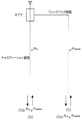
図2は、スマートアンテナシステムでキャリブレーション原理を示す図である。各々送信経路と受信経路にキャリブレーション信号が送信されると、キャリブレーション信号がアンテナまで到達する経路とキャリブレーション信号がフィードバックされる経路により、送信されたキャリブレーション信号に比べて受信されたキャリブレーション受信信号は位相と大きさの変化が発生する。もし、N個のアンテナが存在すると、キャリブレーション信号C(t)はN個の経路で受信される。 FIG. 2 is a diagram illustrating the calibration principle in the smart antenna system. When a calibration signal is transmitted to each transmission path and reception path, the calibration signal received compared to the transmitted calibration signal by the path where the calibration signal reaches the antenna and the path where the calibration signal is fed back The received signal changes in phase and magnitude. If there are N antennas, the calibration signal C (t) is received through N paths.

キャリブレーションのためのビーム係数であるキャリブレーションベクトルを計算するために、それぞれの経路に含まれているカプラ特性Rcouplerを除去すべく、またビーム形成のためにはN個のアンテナの相対的位相を合わせると良い。このようにして、キャリブレーションのためのビーム係数であるキャリブレーションベクトルを、次の式で計算可能である。 To calculate the calibration vector is the beam coefficient for calibration, to remove the coupler characteristic R coupler contained in each path, also for beam formation of the N antennas of the relative phase It is good to match. In this way, a calibration vector that is a beam coefficient for calibration can be calculated by the following equation.
直交周波数分割多重接続(OFDMA)システムのように複数の直交周波数キャリアを使用する通信システムで、スマートアンテナを適用するためにはすべてのキャリアに対するキャリブレーションを周期的に行うべきである。このようなキャリブレーションを行うためには、キャリブレーション信号を発生して周波数資源を割り当てるべきである。しかしながら、このようなキャリブレーション信号のために別途の周波数資源を割り当てることは周波数資源の浪費をもたらすため、これに対する改善が必要である。 In a communication system using a plurality of orthogonal frequency carriers, such as an orthogonal frequency division multiple access (OFDMA) system, in order to apply a smart antenna, calibration for all carriers should be periodically performed. In order to perform such calibration, a calibration signal should be generated and frequency resources should be allocated. However, since the allocation of a separate frequency resource for such a calibration signal results in a waste of the frequency resource, an improvement to this is necessary.
したがって、上記したような問題点を解決するために、本発明の目的は、スマートアンテナを使用する多重搬送波通信システムで、信号の位相と大きさの制御のための改善されたキャリブレーション装置及び方法を提供することにある。 Accordingly, in order to solve the above problems, an object of the present invention is to provide an improved calibration apparatus and method for controlling the phase and magnitude of a signal in a multi-carrier communication system using a smart antenna. Is to provide.
本発明の他の目的は、スマートアンテナを使用する多重搬送波通信システムで、データを割り当てた後の残りのキャリアを優先的に用いて信号の位相と大きさの制御のためのキャリブレーション信号を伝送し、データ伝送に用いられる周波数資源の効率的な活用が可能なキャリブレーション装置及び方法を提供することにある。 Another object of the present invention is to transmit a calibration signal for controlling the phase and magnitude of a signal in a multi-carrier communication system using a smart antenna by preferentially using the remaining carrier after data allocation. Another object of the present invention is to provide a calibration apparatus and method capable of efficiently using frequency resources used for data transmission.
上記した目的を達成するために、本発明によるスマートアンテナ多重搬送波通信システムは、データ信号を複数のキャリアに割り当てて基底帯域プロセッサーに伝送し、キャリブレーション信号処理部で前記複数のキャリアのうち、前記データ信号が割り当てられないキャリアに割り当てられるキャリブレーション信号を発生するように制御するスケジューラと、前記スケジューラによって制御され、前記データ信号が割り当てられないキャリアに前記キャリブレーション信号を発生して割り当て、前記キャリブレーション信号と前記キャリブレーション信号が送信経路を経て受信されたキャリブレーション受信信号を用いてキャリブレーションベクトル値を計算して出力するキャリブレーション信号処理部と、前記キャリブレーション信号処理部が計算した前記キャリブレーションベクトル値を受信し、これを適用してビーム係数をキャリブレーションし、キャリブレーションされたデータ信号を送信経路に伝送する前記基底帯域プロセッサーと、を含むことを特徴とする。 In order to achieve the above object, a smart antenna multi-carrier communication system according to the present invention allocates a data signal to a plurality of carriers and transmits the data signal to a baseband processor, and a calibration signal processing unit includes the plurality of carriers among the plurality of carriers. A scheduler that controls to generate a calibration signal that is assigned to a carrier that is not assigned a data signal; and a calibration signal that is controlled by the scheduler and that is assigned to a carrier that is not assigned a data signal. A calibration signal processing unit that calculates and outputs a calibration vector value using a calibration reception signal in which a calibration signal and the calibration signal are received via a transmission path, and the calibration signal The baseband processor receiving the calibration vector value calculated by the processing unit, applying the calibration vector value to calibrate the beam coefficient, and transmitting the calibrated data signal to the transmission path; To do.
また、本発明によるスマートアンテナ多重搬送波通信システムは、キャリブレーション信号発生部で端末機から受信されたデータ信号が割り当てられないキャリアに割り当てられるキャリブレーション信号を発生するように制御するスケジューラと、前記スケジューラによって制御されて前記データ信号が割り当てられないキャリアに前記キャリブレーション信号を発生して割り当て、前記キャリブレーション信号と前記キャリブレーション信号が受信経路を経て受信されたキャリブレーション受信信号を用いてキャリブレーションベクトル値を計算して出力するキャリブレーション信号処理部と、前記キャリブレーションベクトルプロセッサーが計算した前記キャリブレーションベクトル値を受信してこれを適用してビーム係数をキャリブレーションし、キャリブレーションされたデータ信号を受信経路に伝送する前記基底帯域プロセッサーと、を含むことを特徴とする。 The smart antenna multi-carrier communication system according to the present invention includes a scheduler for controlling a calibration signal generator to generate a calibration signal assigned to a carrier to which a data signal received from a terminal is not assigned, and the scheduler The calibration vector is generated and assigned to a carrier controlled by the data signal to which the data signal is not assigned, and the calibration signal and the calibration signal received via the reception path are used as a calibration vector. A calibration signal processing unit that calculates and outputs a value, and receives the calibration vector value calculated by the calibration vector processor and applies the calibration vector value to the calibrated beam coefficient. And Shon, characterized by comprising said baseband processor to transmit the calibration data signals to the receive path, the.
本発明は、スマートアンテナを用いる多重搬送波通信システムのキャリブレーション信号を割り当てる方法であって、n番目のキャリアのタイマ値をタイマの閾値と比較する段階と、もし、n番目のキャリアのタイマ値がタイマ閾値より大きいと、キャリアにデータを割り当てられない段階と、もし、n番目のキャリアのタイマ値がタイマ閾値より大きくないと、n番目のキャリアにデータを割り当てる段階と、前記データを割り当てる段階でデータが割り当てられないと、キャリブレーション信号を割り当てる段階と、を有することを特徴とする。 The present invention is a method for assigning a calibration signal for a multi-carrier communication system using a smart antenna, the step of comparing the timer value of the nth carrier with the threshold value of the timer, and the timer value of the nth carrier is If it is greater than the timer threshold, data cannot be assigned to the carrier; if the timer value of the nth carrier is not greater than the timer threshold, data is assigned to the nth carrier; and the data is assigned. Assigning a calibration signal if no data is assigned.
さらに、本発明は、スマートアンテナ多重搬送波通信システムのキャリブレーションベクトル推定方法であって、キャリブレーション信号が割り当てられたキャリアを通じてキャリブレーション信号の受信信号を受信する段階と、前記受信されたキャリブレーション受信信号を以前の受信信号の値が格納されているn番目のアドレスのメモリにアップデートする段階と、前記受信信号の受信段階と、前記メモリアップデートの段階をシンボル内のすべてのキャリアに対して反復遂行する段階と、前記メモリに格納されているアップデートされたキャリブレーション受信信号の値を用いてキャリア別にキャリブレーションベクトルを求める段階と、を有することを特徴とする。 The present invention further relates to a calibration vector estimation method for a smart antenna multi-carrier communication system, the step of receiving a received signal of a calibration signal through a carrier to which a calibration signal is assigned, and the received calibration reception. Updating the signal to the memory at the nth address where the value of the previous received signal is stored, receiving the received signal, and repeating the memory update for all carriers in the symbol And a step of obtaining a calibration vector for each carrier using the updated value of the calibration reception signal stored in the memory.
また、本発明は、スマートアンテナを使用する多重搬送波通信システムの信号キャリブレーション方法であって、データ信号を複数のキャリアに割り当てる段階と、前記データ信号が割り当てられないキャリアにキャリブレーション信号を割り当てて伝送する段階と、前記キャリブレーション信号と前記キャリブレーション信号が送信経路を経て受信されたキャリブレーション受信信号を用いてキャリブレーションベクトル値を計算して出力する段階と、前記キャリブレーションベクトル値を受信し、これを適用してビーム係数をキャリブレーションし、キャリブレーションされたデータ信号を送信経路に伝送する段階と、を有することを特徴とする。 The present invention also provides a signal calibration method for a multi-carrier communication system using a smart antenna, the step of assigning a data signal to a plurality of carriers, and assigning a calibration signal to a carrier to which the data signal is not assigned. Transmitting, calculating and outputting a calibration vector value using the calibration signal and a calibration reception signal in which the calibration signal is received through a transmission path, and receiving the calibration vector value. And applying this to calibrate the beam coefficient and transmitting the calibrated data signal to the transmission path.
本発明は、スマートアンテナを使用する多重搬送波通信システムで、複数のキャリアの中でデータを割り当てた後の残りのキャリアを優先的に用いてキャリブレーション信号を伝送することによって、データ伝送に使用される周波数資源を効率的に活用することができる効果がある。 INDUSTRIAL APPLICABILITY The present invention is a multi-carrier communication system using a smart antenna, and is used for data transmission by transmitting a calibration signal preferentially using the remaining carriers after allocating data among a plurality of carriers. The frequency resource can be efficiently utilized.
以下、本発明の望ましい実施形態を添付の図面を参照して詳細に説明する。
直交周波数分割多重接続(OFDMA)システムのように複数の直交周波数キャリアを使用する通信システムで、スマートアンテナを適用するためにはすべてのキャリアに対するキャリブレーションを周期的に行うべきである。
Hereinafter, exemplary embodiments of the present invention will be described in detail with reference to the accompanying drawings.
In a communication system using a plurality of orthogonal frequency carriers, such as an orthogonal frequency division multiple access (OFDMA) system, in order to apply a smart antenna, calibration for all carriers should be periodically performed.
まず、このような通信システムでデータがキャリアに割り当てられる過程について説明する。
図3は、本発明によるスマートアンテナ通信システムでデータ信号がキャリアに割り当てられる過程を示す図である。図3で、黒色領域はデータが割り当てられる領域で、ブランク領域はその領域の中から選択してキャリブレーション信号を割り当てる領域である。すなわち、時間の変化によってデータがキャリアに割り当てられる例を示す。時間の変化により基地局に接続された端末機ユーザーが変化すると、それによって、データの周波数資源割り当ても変化する。また、時間の変化によりデータが割り当てられないキャリアも変わるようになる。
First, a process in which data is assigned to a carrier in such a communication system will be described.
FIG. 3 is a diagram illustrating a process of assigning data signals to carriers in the smart antenna communication system according to the present invention. In FIG. 3, a black area is an area to which data is assigned, and a blank area is an area to which a calibration signal is assigned by selecting from the area. That is, an example is shown in which data is allocated to carriers according to changes in time. When the terminal user connected to the base station changes due to the change of time, the frequency resource allocation of data also changes accordingly. Also, the carrier to which data is not allocated changes with time.
データが割り当てられないキャリアにキャリブレーション信号を割り当てると、データが割り当てられないキャリアに対するキャリブレーションが可能である。データが割り当てられない残りのキャリアを通じて一定の時間でキャリブレーションを続けると、全体周波数帯域のキャリブレーションが可能になる。しかしながら、全帯域のキャリブレーションが效率的に行われるためには、残りのキャリアの位置が全帯域に均等に分布しなければならない。また、一定のキャリアに キャリブレーション信号を割り当てた後に、一定の時間(Time_threshold)が過ぎる間に同一のキャリアにキャリブレーション信号が更に割り当てられないと、強制的にキャリブレーション信号を割り当て可能にする。 When a calibration signal is assigned to a carrier to which no data is assigned, calibration for a carrier to which no data is assigned is possible. If calibration is continued for a certain period of time through the remaining carriers to which no data is allocated, calibration of the entire frequency band becomes possible. However, in order for calibration of the entire band to be performed efficiently, the positions of the remaining carriers must be evenly distributed over the entire band. Further, after allocating a calibration signal to a certain carrier, that enables assignment when calibration signal on the same carrier during the predetermined time (Time_threshold) passes is not further assigned, forcibly calibration signal .
図4は、本発明によるスマートアンテナシステムのキャリブレーション装置の構成を示すブロック構成図である。図4の参照番号401〜410は、各々図1の参照番号101〜110の構成要素と同一である。図4の参照番号411〜414の構成要素が、本発明のキャリブレーション信号の割り当て過程とキャリブレーションベクトル推定過程を遂行する部分である。ここで、スケジューラ412は、シンボルごとにキャリブレーションを考慮してデータ信号をキャリアに割り当てる。キャリアに割り当てられたデータ信号は、基底帯域プロセッサー(base band processor)411に伝送される。また、スケジューラ412は、キャリブレーション信号発生部413とキャリブレーションベクトルプロセッサー414を制御する。すなわち、スケジューラは、キャリブレーション信号発生部413でデータが割り当てられないキャリアにキャリブレーション信号を割り当てるようにする。また、キャリブレーションベクトルプロセッサー414は、送信したキャリブレーション信号が経路を経て受信されたキャリブレーション受信信号を用いてキャリブレーションベクトルを求めるように制御する。図1で説明したキャリブレーション信号の送信経路と受信経路の伝送及び受信過程は、同一に適用される。
FIG. 4 is a block diagram showing the configuration of the calibration device for the smart antenna system according to the present invention. Reference numerals 401 to 410 in FIG. 4 are the same as the components of
図5は、本発明にるスマートアンテナシステムの基底帯域プロセッサー411を示す図である。基底帯域モジュール108を構成する基底帯域プロセッサー411は、キャリブレーション信号処理部110のキャリブレーションベクトルプロセッサー414からキャリブレーションベクトルを受信して適用する。基地局から端末機にデータ信号を送信する経路で、データマッパー504はスケジューラによってビーム係数が適用されてキャリア別に割り当てられたデータを受信する。キャリブレーター503は、キャリブレーションベクトルプロセッサー414からキャリブレーションベクトルを受信し、これを乗算器502に伝送してキャリア別信号にキャリブレーションベクトルを適用する。以後、IFFTブロック501によって変調される。
FIG. 5 is a diagram illustrating the baseband processor 411 of the smart antenna system according to the present invention. The baseband processor 411 configuring the
基地局で端末機からデータ信号を受信する経路で、上記の送信経路の逆過程が遂行される。受信したデータ信号をFFTブロック501が復調し、キャリブレーター503がキャリブレーションベクトルプロセッサー414から受信したキャリブレーションベクトルを適用する。
The reverse process of the transmission path is performed in a path for receiving a data signal from the terminal at the base station. The
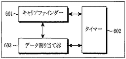
図6は、本発明によるスマートアンテナシステムのスケジューラ412の構成を示す図である。このスケジューラは、キャリブレーション信号発生部を制御してキャリブレーション信号を割り当てる機能を遂行する。キャリアファインダー(Carrier_set Finder)601は、タイマー602の値が基準値(Time_threshold)を超えないデータ割り当て可能キャリアを検索する。データ割り当て器(data allocator)603は、キャリアファインダー601が検索したデータ割り当て可能キャリアにデータ信号を割り当てる。タイマー602は、データ割り当て器603によって割り当てられたデータ信号値を用いてタイマー602の基準値をアップデートする。
FIG. 6 is a diagram showing a configuration of the scheduler 412 of the smart antenna system according to the present invention. The scheduler performs a function of controlling a calibration signal generator and allocating a calibration signal. The carrier finder (Carrier_set Finder) 601 searches for a data assignable carrier in which the value of the
図7は、本発明によるスマートアンテナシステムのキャリブレーション信号発生部の構成を示す図である。キャリブレーション信号発生部(Calibration Signal Generator)413は、キャリブレーション信号割り当て器701と、IFFTブロック702とから構成される。キャリブレーション信号割り当て器701は、スケジューラ412から伝送されたキャリア間データ割り当て情報により、データが割り当てられないキャリアにキャリブレーション信号を割り当てる。IFFTブロック702は、キャリアに割り当てられたキャリブレーション信号を変調する。
FIG. 7 is a diagram illustrating a configuration of a calibration signal generation unit of the smart antenna system according to the present invention. A calibration signal generator (Calibration Signal Generator) 413 includes a
図8は、本発明によるスマートアンテナシステムのキャリブレーションベクトルプロセッサー414の構成を示す図である。キャリブレーションベクトルプロセッサー414は、FFTブロック801と、キャリブレーション信号獲得器(Calibration Signal Acquirer)802と、キャリブレーション信号アップデート部(Calibration Siganl Updater)803と、インターポレータ(Interpolator)804と、キャリブレーションベクトル計算部(Calibration Vector Calculator)805とから構成される。FFTブロック801は、受信されたキャリブレーション受信信号をキャリア別信号に分離する。キャリブレーション信号獲得器802は、スケジューラからキャリブレーション信号のキャリア位置情報を用いてキャリブレーション信号が割り当てられたキャリアのキャリブレーション受信信号の大きさと位相情報を測定する。キャリブレーション信号アップデート部803は、この情報を毎時間ごとにアップデートしてメモリに格納する。インターポレータ804は、メモリに格納されたキャリブレーション信号をインターポレーションしてキャリブレーション信号が割り当てられないキャリアのキャリブレーション信号を予測する。このインターポレータ804は、上記したように、端末機ユーザーが多い場合に使用される。キャリブレーションベクトル計算部805は、キャリブレーション受信信号値からカプラーの特性を除去した後に、キャリブレーションベクトルを計算する。
FIG. 8 is a diagram illustrating a configuration of the
図9は、本発明によるスマートアンテナシステムのキャリブレーション信号割り当て過程を示すフローチャートである。以下の各ステップは、基地局制御部409の制御の下に基底帯域プロセッサー411によって遂行される。
FIG. 9 is a flowchart illustrating a calibration signal assignment process of the smart antenna system according to the present invention. The following steps are performed by the baseband processor 411 under the control of the
図9を参照すると、基地局が作動される前にキャリア別タイマーが0にリセットされる。キャリアを示す変数nは1に定める(ステップS901)。n番目のキャリアのタイマ値をタイマ閾値と比較する(ステップS902)。その結果、n番目のキャリアのタイマ値が閾値より大きいと、キャリアにデータを割り当てない(ステップS903)。ステップS904で、nがn+1にアップデートされた後に、ステップS903に戻る。一方、ステップS902で、n番目のキャリアのタイマ値が閾値より大きくないと、n番目のキャリアにデータを割り当てる(ステップS905)。データがすべてのデータキャリアに割り当てられることではないため、データが割り当てられないデータキャリアが存在する可能性がある。データが割り当てられたか否かを判断し(ステップS906)、データが割り当てられない場合には、ステップS907に進んで、キャリブレーション信号を割り当てる。次に、キャリブレーション信号とデータ信号を含むシンボルが伝送される。 Referring to FIG. 9, the carrier-specific timer is reset to 0 before the base station is activated. A variable n indicating a carrier is set to 1 (step S901). The timer value of the nth carrier is compared with the timer threshold value (step S902). As a result, if the timer value of the nth carrier is larger than the threshold value, no data is assigned to the carrier (step S903). In step S904, after n is updated to n + 1, the process returns to step S903. On the other hand, if the timer value of the nth carrier is not greater than the threshold value in step S902, data is allocated to the nth carrier (step S905). Since data is not assigned to all data carriers, there may be data carriers to which no data is assigned. It is determined whether or not data has been assigned (step S906). If no data is assigned, the process proceeds to step S907 to assign a calibration signal. Next, a symbol including a calibration signal and a data signal is transmitted.
図10は、本発明によるスマートアンテナシステムのキャリブレーションベクトル推定過程を示すフローチャートである。以下の各ステップは、基地局制御部409の制御の下に基底帯域プロセッサー411によって遂行される。
FIG. 10 is a flowchart illustrating a calibration vector estimation process of the smart antenna system according to the present invention. The following steps are performed by the baseband processor 411 under the control of the
このキャリブレーションベクトル推定過程を説明すると、次のようである。キャリアを示す変数nは1に定める(ステップS1001)。nがN(キャリアの全体数)以下であるか否かを判断し(ステップS1002)、その結果、nがNより小さいと、ステップS1005に進む。n番目のキャリアにキャリブレーション信号が割り当てられるか否かを判断する(ステップS1005)。その結果、キャリブレーション信号が割り当てられると、キャリブレーション信号に対する応答信号を受信し、キャリブレーションキャリアの位相と振幅をメモリに格納する(ステップS1006)。次に、以前キャリアのキャリブレーション信号の位相と振幅を有するメモリのn番目のアドレスに、n番目のキャリアに対するキャリブレーション信号の位相と振幅をアップデートする(ステップS1007)。この動作は、すべてのキャリアに対して反復する。一方、ステップS1002の判断結果、nがN以上であると、格納されたキャリアの位相と振幅を用いてインターポレーションする(ステップS1003)。次に、キャリブレーション信号からカプラーの特性を除去した後に、キャリア別にキャリブレーションベクトルを求める(ステップS1004)。 The calibration vector estimation process will be described as follows. A variable n indicating a carrier is set to 1 (step S1001). It is determined whether n is equal to or less than N (the total number of carriers) (step S1002). If n is smaller than N as a result, the process proceeds to step S1005. It is determined whether a calibration signal is assigned to the nth carrier (step S1005). As a result, when the calibration signal is assigned, a response signal to the calibration signal is received, and the phase and amplitude of the calibration carrier are stored in the memory (step S1006). Next, the phase and amplitude of the calibration signal for the nth carrier are updated to the nth address of the memory having the phase and amplitude of the calibration signal of the previous carrier (step S1007). This operation repeats for all carriers. On the other hand, if n is greater than or equal to N as a result of the determination in step S1002, interpolation is performed using the stored carrier phase and amplitude (step S1003). Next, after removing the coupler characteristics from the calibration signal, a calibration vector is obtained for each carrier (step S1004).
図11A及び図11Bは、本発明によるスマートアンテナシステムのキャリブレーション信号の受信値を示す図である。
図11Aは、一定の時間で時間ごとにキャリブレーション信号を伝送した後に任意の時間でキャリブレーション信号を受信することを示す。このように、毎時間のキャリブレーション信号の受信値を一定時間格納すると、全帯域のキャリブレーションが可能である。システムでは送信したキャリブレーション信号値を知っているため、このような送信キャリブレーション信号値と上記のキャリブレーション受信信号値とを比較すると、キャリブレーションベクトルを計算することができ、信号の位相と大きさをキャリブレーションすることができる。基地局に接続された端末機ユーザーが少ない場合には、このような方法を使用する。
11A and 11B are diagrams illustrating received values of calibration signals of the smart antenna system according to the present invention.
FIG. 11A shows that the calibration signal is received at an arbitrary time after the calibration signal is transmitted every hour at a constant time. In this way, if the received value of the calibration signal every hour is stored for a certain period of time, calibration of the entire band is possible. Since the system knows the transmitted calibration signal value, the calibration vector can be calculated by comparing the transmitted calibration signal value with the above calibration received signal value, and the phase and magnitude of the signal can be calculated. Can be calibrated. This method is used when there are few terminal users connected to the base station.
図11Bは、図11Aに類似するが、全帯域にわたってキャリブレーション信号を伝送しない場合を示す。すなわち、この場合にインターポレーション(interpolation)技法を使用してキャリブレーション信号の受信値を推定する。基地局に接続されたユーザーが多い場合に、データ割り当てにより多くのキャリアを使用すべきなため、このような方法を使用することが必要である。ここで、システムは送信したキャリブレーション信号値を知っているため、このような送信キャリブレーション信号値と上記のキャリブレーション受信信号値とを比較すると、キャリブレーションベクトルが計算でき、信号の位相と大きさをキャリブレーションすることができる。 FIG. 11B is similar to FIG. 11A, but shows the case where the calibration signal is not transmitted across the entire band. That is, in this case, the received value of the calibration signal is estimated using an interpolation technique. It is necessary to use such a method because if there are many users connected to the base station, more carriers should be used for data allocation. Here, since the system knows the transmitted calibration signal value, the calibration vector can be calculated by comparing the transmitted calibration signal value with the above calibration received signal value, and the phase and magnitude of the signal can be calculated. Can be calibrated.
以上、本発明の詳細な説明においては具体的な実施形態に関して説明したが、本発明の範囲を外れない限り、様々な変形が可能であることは、当該技術分野における通常の知識を持つ者には自明なことであろう。したがって、本発明の範囲は、前述の実施形態に限定されるものではなく、特許請求の範囲の記載及びこれと均等なものに基づいて定められるべきである。 As described above, the specific embodiments have been described in the detailed description of the present invention. However, various modifications can be made without departing from the scope of the present invention to those skilled in the art. Will be obvious. Therefore, the scope of the present invention should not be limited to the above-described embodiments, but should be determined based on the description of the claims and equivalents thereof.
401 アンテナ
402 カプラ-コンバイナ/カプラ-スプリッタ
403 TCB
404 Txモジュール
405 Rxモジュール
406 DUC
407 DDC
408 基底帯域モジュール
409 基地局制御部
410 キャリブレーション信号処理部
411 基底帯域プロセッサー
412 スケジューラ
413 キャリブレーション信号発生部
414 キャリブレーションベクトルプロセッサー
401
404
407 DDC
408
Claims (16)
前記スケジューラによって制御され、前記データ信号が割り当てられないキャリアに前記キャリブレーション信号を発生して割り当て、前記キャリブレーション信号と前記キャリブレーション信号が送信経路を経て受信されたキャリブレーション受信信号を用いてキャリブレーションベクトル値を計算して出力するキャリブレーション信号処理部と、
前記キャリブレーション信号処理部が計算した前記キャリブレーションベクトル値を受信し、これを適用してビーム係数をキャリブレーションし、キャリブレーションされたデータ信号を送信経路に伝送する前記基底帯域プロセッサーと、
を含み、
キャリブレーション信号が一定の時間の間に2回以上割り当てられなかったキャリアに対してキャリブレーション信号を割り当てるために、前記スケジューラは、前記複数のキャリアのうち前記キャリブレーション信号が一定の時間の間に2回以上割り当てられなかったキャリアに前記データ信号を割り当てないことを特徴とするスマートアンテナ多重搬送波通信システム。 A data signal is allocated to a plurality of carriers and transmitted to a baseband processor, and a calibration signal processing unit is controlled to generate a calibration signal allocated to a carrier to which the data signal is not allocated among the plurality of carriers. A scheduler,
The calibration signal is generated and assigned to a carrier controlled by the scheduler and to which the data signal is not assigned, and the calibration signal and the calibration signal are calibrated using a calibration reception signal received via a transmission path. A calibration signal processing unit that calculates and outputs a calibration vector value;
The baseband processor that receives the calibration vector value calculated by the calibration signal processing unit, applies this to calibrate the beam coefficient, and transmits the calibrated data signal to the transmission path;
Including
In order to assign a calibration signal to a carrier for which a calibration signal has not been assigned more than once during a certain period of time, the scheduler is configured such that the calibration signal among the plurality of carriers falls within a certain period of time. A smart antenna multi-carrier communication system, wherein the data signal is not assigned to a carrier that has not been assigned more than once .
前記スケジューラによって制御され、前記データ信号が割り当てられないキャリアに前記キャリブレーション信号を発生して割り当てる前記キャリブレーション信号発生部と、
前記キャリブレーション信号と前記キャリブレーション信号が送信経路を経て受信されたキャリブレーション受信信号を用いてキャリブレーションベクトル値を計算して出力するキャリブレーションベクトルプロセッサーと、
を含むことを特徴とする請求項1記載のスマートアンテナ多重搬送波通信システム。 The calibration signal processing unit
The calibration signal generator that is controlled by the scheduler and generates and assigns the calibration signal to a carrier to which the data signal is not assigned;
A calibration vector processor that calculates and outputs a calibration vector value using the calibration signal and a calibration reception signal in which the calibration signal is received via a transmission path;
The smart antenna multi-carrier communication system according to claim 1, comprising:
前記スケジューラによってキャリア別に割り当てられたデータ信号を受信するデータマッパーと、
前記データ信号に前記キャリブレーションベクトルプロセッサーから受信されたキャリブレーションベクトルを適用するキャリブレーターと、
前記キャリブレーターに前記キャリブレーションベクトルが適用された前記データ信号を変調するIFFTブロックと、
を含むことを特徴とする請求項1記載のスマートアンテナ多重搬送波通信システム。 The baseband processor is
A data mapper for receiving data signals allocated by carrier by the scheduler;
A calibrator for applying a calibration vector received from the calibration vector processor to the data signal;
An IFFT block that modulates the data signal to which the calibration vector is applied to the calibrator;
The smart antenna multi-carrier communication system according to claim 1, comprising:
前記スケジューラから伝送されたキャリア間のデータ割り当て情報により、データが割り当てられないキャリアにキャリブレーション信号を割り当てるキャリブレーション信号割り当て部と、
前記キャリアに割り当てられたキャリブレーション信号を変調するIFFTブロックと、
を含むことを特徴とする請求項2記載のスマートアンテナ多重搬送波通信システム。 The calibration signal generator is
A calibration signal allocation unit that allocates a calibration signal to a carrier to which data is not allocated according to data allocation information between carriers transmitted from the scheduler;
An IFFT block that modulates a calibration signal assigned to the carrier;
The smart antenna multi-carrier communication system according to claim 2, comprising:
前記キャリブレーション受信信号をキャリア別信号に分離するFFTブロックと、
前記スケジューラからのキャリブレーション信号のキャリア位置情報を用いてキャリブレーション信号が割り当てられたキャリアの前記キャリブレーション受信信号の大きさと位相値を測定するキャリブレーション信号獲得器と、
前記キャリブレーション受信信号の大きさと位相値を時間ごとにアップデートしてメモリに格納するキャリブレーション信号アップデート部と、
前記メモリに格納された前記キャリブレーション受信信号の大きさと位相値でカプラーの特性を除去した後に、キャリブレーションベクトルを計算するキャリブレーションベクトル計算部と、
を含むことを特徴とする請求項2記載のスマートアンテナ多重搬送波通信システム。 The calibration vector processor is
An FFT block for separating the calibration reception signal into carrier-specific signals;
A calibration signal acquirer that measures the magnitude and phase value of the calibration reception signal of a carrier to which a calibration signal is assigned using the carrier position information of the calibration signal from the scheduler;
A calibration signal update unit that updates the magnitude and phase value of the calibration reception signal every time and stores them in a memory;
A calibration vector calculation unit for calculating a calibration vector after removing the characteristics of the coupler with the magnitude and phase value of the calibration reception signal stored in the memory;
The smart antenna multi-carrier communication system according to claim 2, comprising:
前記スケジューラによって制御されて前記データ信号が割り当てられないキャリアに前記キャリブレーション信号を発生して割り当て、前記キャリブレーション信号と前記キャリブレーション信号が受信経路を経て受信されたキャリブレーション受信信号を用いてキャリブレーションベクトル値を計算して出力するキャリブレーション信号処理部と、
前記キャリブレーションベクトルプロセッサーが計算した前記キャリブレーションベクトル値を受信してこれを適用してビーム係数をキャリブレーションし、キャリブレーションされたデータ信号を受信経路に伝送する前記基底帯域プロセッサーと、
を含み、
キャリブレーション信号が一定の時間の間に2回以上割り当てられなかったキャリアに対してキャリブレーション信号を割り当てるために、前記スケジューラは、前記複数のキャリアのうち前記キャリブレーション信号が一定の時間の間に2回以上割り当てられなかったキャリアに前記データ信号を割り当てないことを特徴とするスマートアンテナ多重搬送波通信システム。 A scheduler for controlling a calibration signal generator to generate a calibration signal assigned to a carrier to which a data signal received from a terminal is not assigned;
The calibration signal is generated and assigned to a carrier that is controlled by the scheduler and to which the data signal is not assigned, and the calibration signal and the calibration signal are calibrated using a calibration reception signal received via a reception path. A calibration signal processing unit that calculates and outputs a calibration vector value;
Receiving the calibration vector value calculated by the calibration vector processor, applying the calibration vector value to calibrate the beam coefficient, and transmitting the calibrated data signal to the reception path;
Including
In order to assign a calibration signal to a carrier for which a calibration signal has not been assigned more than once during a certain period of time, the scheduler is configured such that the calibration signal among the plurality of carriers falls within a certain period of time. A smart antenna multi-carrier communication system, wherein the data signal is not assigned to a carrier that has not been assigned more than once .
前記スケジューラによって制御されて前記データ信号が割り当てられないキャリアに前記キャリブレーション信号を発生して割り当てる前記キャリブレーション信号発生部と、
前記キャリブレーション信号と前記キャリブレーション信号が受信経路を経て受信されたキャリブレーション受信信号を用いてキャリブレーションベクトル値を計算して出力するキャリブレーションベクトルプロセッサーと、
を含むことを特徴とする請求項7記載のスマートアンテナ多重搬送波通信システム。 The calibration signal processing unit
The calibration signal generator that generates and assigns the calibration signal to a carrier that is controlled by the scheduler and to which the data signal is not assigned;
A calibration vector processor for calculating and outputting a calibration vector value using the calibration signal and a calibration reception signal received via the reception path of the calibration signal; and
The smart antenna multi-carrier communication system according to claim 7, comprising:
キャリブレーション信号が割り当てられたキャリアを通じてキャリブレーション信号の受信信号を受信する段階と、
前記受信されたキャリブレーション受信信号を以前の受信信号の値が格納されているn番目のアドレスのメモリにアップデートする段階と、
前記受信信号の受信段階と、前記メモリアップデートの段階をシンボル内のすべてのキャリアに対して反復遂行する段階と、
前記メモリに格納されているアップデートされたキャリブレーション受信信号の値を用いてキャリア別にキャリブレーションベクトルを求める段階と、
を有し、
キャリブレーション信号が一定の時間の間に2回以上割り当てられなかったキャリアに対してキャリブレーション信号を割り当てるために、前記複数のキャリアのうち前記キャリブレーション信号が一定の時間の間に2回以上割り当てられなかったキャリアにデータ信号を割り当てないことを特徴とする方法。 A calibration vector estimation method for a smart antenna multi-carrier communication system, comprising:
Receiving a calibration signal reception signal through a carrier to which the calibration signal is assigned;
Updating the received calibration reception signal to the memory at the nth address where the value of the previous reception signal is stored;
Receiving the received signal; repeating the memory update for all carriers in a symbol;
Obtaining a calibration vector for each carrier using a value of the updated calibration reception signal stored in the memory;
Have
In order to assign a calibration signal to a carrier for which a calibration signal has not been assigned more than once during a certain time, the calibration signal among the plurality of carriers is assigned more than once during a certain time. A method characterized by not assigning a data signal to a carrier that has not been received .
データ信号を複数のキャリアに割り当てる段階と、
前記データ信号が割り当てられないキャリアにキャリブレーション信号を割り当てて伝送する段階と、
前記キャリブレーション信号と前記キャリブレーション信号が送信経路を経て受信されたキャリブレーション受信信号を用いてキャリブレーションベクトル値を計算して出力する段階と、
前記キャリブレーションベクトル値を受信し、これを適用してビーム係数をキャリブレーションし、キャリブレーションされたデータ信号を送信経路に伝送する段階と、
を有し、
キャリブレーション信号が一定の時間の間に2回以上割り当てられなかったキャリアに対してキャリブレーション信号を割り当てるために、前記複数のキャリアのうち前記キャリブレーション信号が一定の時間の間に2回以上割り当てられなかったキャリアに前記データ信号を割り当てないことを特徴とする方法。 A signal calibration method for a multi-carrier communication system using a smart antenna,
Assigning data signals to multiple carriers;
Assigning and transmitting a calibration signal to a carrier to which the data signal is not assigned;
Calculating and outputting a calibration vector value using the calibration signal and a calibration reception signal in which the calibration signal is received via a transmission path; and
Receiving the calibration vector value, applying it to calibrate the beam coefficients, and transmitting the calibrated data signal to the transmission path;
Have
In order to assign a calibration signal to a carrier for which a calibration signal has not been assigned more than once during a certain time, the calibration signal among the plurality of carriers is assigned more than once during a certain time. A method characterized by not assigning the data signal to a carrier that has not been received .
受信されたキャリア間のデータ割り当て情報によりデータ信号が割り当てられないキャリアにキャリブレーション信号を割り当てる段階と、
前記キャリアに割り当てられたキャリブレーション信号を変調する段階と、
を有することを特徴とする請求項12記載の方法。 Generating, assigning and transmitting a calibration signal to a carrier to which the data signal is not assigned,
Assigning a calibration signal to a carrier to which a data signal is not assigned according to data assignment information between received carriers;
Modulating a calibration signal assigned to the carrier;
13. The method of claim 12, comprising:
前記キャリア別に割り当てられたデータ信号を受信する段階と、
前記データ信号に前記キャリブレーションベクトルプロセッサーから受信されたキャリブレーションベクトルを適用する段階と、
前記キャリブレーターに前記キャリブレーションベクトルが適用された前記データ信号を変調する段階と、
を有することを特徴とする請求項12記載の方法。 Receiving the calibration vector value, applying it to calibrate the beam coefficients, and transmitting the calibrated data signal to the transmission path;
Receiving a data signal assigned to each carrier;
Applying a calibration vector received from the calibration vector processor to the data signal;
Modulating the data signal with the calibration vector applied to the calibrator;
13. The method of claim 12, comprising:
前記キャリブレーション受信信号をキャリア別信号に分離する段階と、
前記キャリブレーション信号のキャリア位置情報を用いてキャリブレーション信号が割り当てられたキャリアの前記キャリブレーション受信信号の大きさと位相値を測定する段階と、
前記キャリブレーション受信信号の大きさと位相値を時間ごとにアップデートしてメモリに貯蔵する段階と、
前記メモリに格納された前記キャリブレーション受信信号の大きさと位相値でカプラーの特性を除去した後に、キャリブレーションベクトルを計算する段階と、
を有することを特徴とする請求項12記載の方法。 The step of calculating and outputting a calibration vector value using the calibration signal and the calibration reception signal in which the calibration signal is received via a transmission path,
Separating the calibration reception signal into carrier-specific signals;
Measuring the magnitude and phase value of the calibration reception signal of the carrier to which the calibration signal is assigned using the carrier position information of the calibration signal;
Updating the calibration received signal magnitude and phase value every time and storing them in memory;
Calculating a calibration vector after removing coupler characteristics with the magnitude and phase value of the calibration received signal stored in the memory; and
13. The method of claim 12, comprising:
Applications Claiming Priority (1)
| Application Number | Priority Date | Filing Date | Title |
|---|---|---|---|
| KR1020040100181A KR100633047B1 (en) | 2004-12-02 | 2004-12-02 | Smart Antenna Communication System Employing Apparatus And Method For Signal Calibration |
Publications (2)
| Publication Number | Publication Date |
|---|---|
| JP2006166452A JP2006166452A (en) | 2006-06-22 |
| JP4455483B2 true JP4455483B2 (en) | 2010-04-21 |
Family
ID=35841700
Family Applications (1)
| Application Number | Title | Priority Date | Filing Date |
|---|---|---|---|
| JP2005349969A Expired - Fee Related JP4455483B2 (en) | 2004-12-02 | 2005-12-02 | Smart antenna communication system for realizing signal correction apparatus and method |
Country Status (5)
| Country | Link |
|---|---|
| US (1) | US7801564B2 (en) |
| EP (1) | EP1670094B1 (en) |
| JP (1) | JP4455483B2 (en) |
| KR (1) | KR100633047B1 (en) |
| CN (1) | CN1783748B (en) |
Families Citing this family (27)
| Publication number | Priority date | Publication date | Assignee | Title |
|---|---|---|---|---|
| US7652577B1 (en) | 2006-02-04 | 2010-01-26 | Checkpoint Systems, Inc. | Systems and methods of beamforming in radio frequency identification applications |
| KR101009781B1 (en) * | 2006-07-11 | 2011-01-19 | 삼성전자주식회사 | Apparatus and method for calibration in a communication system |
| US7873326B2 (en) | 2006-07-11 | 2011-01-18 | Mojix, Inc. | RFID beam forming system |
| EP2067278B1 (en) * | 2006-08-22 | 2016-06-15 | Koninklijke Philips N.V. | Method for transmitting data in a mobile system and radio stations therefor |
| US20080207258A1 (en) * | 2007-02-26 | 2008-08-28 | Broadcom Corporation, A California Corporation | Multimode transmitter with digital up conversion and methods for use therewith |
| US20090093222A1 (en) * | 2007-10-03 | 2009-04-09 | Qualcomm Incorporated | Calibration and beamforming in a wireless communication system |
| CN101414875B (en) * | 2007-10-15 | 2013-06-26 | 中国移动通信集团上海有限公司 | Method, equipment and system for shrouding tunnel of TDD system |
| EP2235921A2 (en) * | 2008-01-22 | 2010-10-06 | Provigent Ltd. | Beamforming in mimo communication systems |
| KR101452999B1 (en) * | 2008-01-25 | 2014-10-21 | 삼성전자주식회사 | Apparatus and method for calibration in multi-antenna system |
| US8217760B2 (en) * | 2008-03-20 | 2012-07-10 | Checkpoint Systems, Inc. | Applique nodes for performance and functionality enhancement in radio frequency identification systems |
| WO2009151778A2 (en) | 2008-04-14 | 2009-12-17 | Mojix, Inc. | Radio frequency identification tag location estimation and tracking system and method |
| CN101304276B (en) * | 2008-06-30 | 2012-07-04 | 华为技术有限公司 | Method and system for transmitting channel correction |
| JP2010021784A (en) * | 2008-07-10 | 2010-01-28 | Sony Corp | Communication apparatus, and communication calibration method |
| US8786440B2 (en) * | 2009-10-02 | 2014-07-22 | Checkpoint Systems, Inc. | Calibration of beamforming nodes in a configurable monitoring device system |
| CN101951618A (en) * | 2010-08-31 | 2011-01-19 | 芯通科技(成都)有限公司 | RRU (Remote Radio Unit) automatic calibration and test system |
| CN102812594B (en) | 2010-09-08 | 2015-08-19 | 华为技术有限公司 | A kind of channel calibration method, Apparatus and system |
| JP5599353B2 (en) * | 2011-03-30 | 2014-10-01 | パナソニック株式会社 | Transceiver |
| US9178737B2 (en) * | 2012-11-20 | 2015-11-03 | Intel Deutschland Gmbh | Method for generating an OFDM data signal |
| US9755707B2 (en) | 2013-01-30 | 2017-09-05 | Telefonaktiebolaget Lm Ericsson (Publ) | Method and apparatus for calibrating multiple antennas |
| US9596676B2 (en) * | 2013-02-13 | 2017-03-14 | Qualcomm Incorporated | Calibration of a downlink transmit path of a base station |
| US20140329472A1 (en) * | 2013-05-03 | 2014-11-06 | CommSense LLC | Antenna Environment Sensing Device |
| US9883337B2 (en) | 2015-04-24 | 2018-01-30 | Mijix, Inc. | Location based services for RFID and sensor networks |
| JP2018019374A (en) | 2016-07-29 | 2018-02-01 | 富士通株式会社 | Base station and antenna calibration method |
| US10326538B2 (en) * | 2017-04-05 | 2019-06-18 | Cisco Technology, Inc. | Remote radio head reciprocity calibration |
| JP2019114961A (en) * | 2017-12-25 | 2019-07-11 | 富士通株式会社 | Radio communication equipment, and antenna calibration method |
| WO2020021628A1 (en) * | 2018-07-24 | 2020-01-30 | 三菱電機株式会社 | Calibration device and calibration method of array antenna, array antenna, and program |
| KR102195541B1 (en) * | 2018-08-10 | 2020-12-28 | 주식회사 다빈시스템스 | Method and Apparatus for Calibrating a Multi-Channel RF System |
Family Cites Families (19)
| Publication number | Priority date | Publication date | Assignee | Title |
|---|---|---|---|---|
| GB2285537B (en) * | 1989-09-28 | 1995-11-08 | Marconi Co Ltd | Calibration of distributed receiver system for antenna array |
| GB2313523B (en) * | 1996-05-23 | 2000-06-07 | Motorola Ltd | Self-calibration apparatus and method for communication device |
| JP3369466B2 (en) | 1997-03-18 | 2003-01-20 | 松下電器産業株式会社 | Calibration device for array antenna wireless receiver |
| US6208287B1 (en) * | 1998-03-16 | 2001-03-27 | Raytheoncompany | Phased array antenna calibration system and method |
| ID27970A (en) * | 1998-08-05 | 2001-05-03 | Sanyo Electric Co | RADAS RADIO AND CALIBRATION METHODS FOR THAT |
| US6184829B1 (en) * | 1999-01-08 | 2001-02-06 | Trueposition, Inc. | Calibration for wireless location system |
| AU763056B2 (en) | 1999-03-30 | 2003-07-10 | Sanyo Electric Co., Ltd. | Radio device and method of calibration of antenna directivity |
| JP2003218621A (en) | 2002-01-21 | 2003-07-31 | Nec Corp | Apparatus and method for calibrating array antenna |
| JP3769513B2 (en) * | 2002-03-19 | 2006-04-26 | 株式会社東芝 | Array antenna device |
| JP4010225B2 (en) | 2002-10-30 | 2007-11-21 | 日本電気株式会社 | Array antenna transceiver |
| KR100608736B1 (en) * | 2003-04-29 | 2006-08-04 | 엘지전자 주식회사 | Apparatus for generating reference signal in a smart antenna system |
| JP4388303B2 (en) | 2003-05-16 | 2009-12-24 | 日本無線株式会社 | Array antenna communication device |
| WO2005022833A2 (en) * | 2003-08-27 | 2005-03-10 | Wavion Ltd. | Wlan capacity enhancement using sdm |
| KR100675489B1 (en) * | 2004-11-23 | 2007-01-29 | 삼성전자주식회사 | Smart Antenna Communication System Employing Apparatus And Method For Signal Calibration |
| US7362266B2 (en) * | 2004-12-07 | 2008-04-22 | Lockheed Martin Corporation | Mutual coupling method for calibrating a phased array |
| US7408507B1 (en) * | 2005-03-15 | 2008-08-05 | The United States Of America As Represented By The Secretary Of The Navy | Antenna calibration method and system |
| US8498669B2 (en) * | 2005-06-16 | 2013-07-30 | Qualcomm Incorporated | Antenna array calibration for wireless communication systems |
| US9118111B2 (en) * | 2005-11-02 | 2015-08-25 | Qualcomm Incorporated | Antenna array calibration for wireless communication systems |
| US8280430B2 (en) * | 2005-11-02 | 2012-10-02 | Qualcomm Incorporated | Antenna array calibration for multi-input multi-output wireless communication systems |
-
2004
- 2004-12-02 KR KR1020040100181A patent/KR100633047B1/en not_active IP Right Cessation
-
2005
- 2005-12-01 EP EP05026272.4A patent/EP1670094B1/en not_active Expired - Fee Related
- 2005-12-02 US US11/293,564 patent/US7801564B2/en not_active Expired - Fee Related
- 2005-12-02 JP JP2005349969A patent/JP4455483B2/en not_active Expired - Fee Related
- 2005-12-02 CN CN2005101310133A patent/CN1783748B/en not_active Expired - Fee Related
Also Published As
| Publication number | Publication date |
|---|---|
| US7801564B2 (en) | 2010-09-21 |
| EP1670094B1 (en) | 2017-05-31 |
| KR100633047B1 (en) | 2006-10-11 |
| US20060135211A1 (en) | 2006-06-22 |
| KR20060061443A (en) | 2006-06-08 |
| CN1783748A (en) | 2006-06-07 |
| JP2006166452A (en) | 2006-06-22 |
| EP1670094A1 (en) | 2006-06-14 |
| CN1783748B (en) | 2010-05-12 |
Similar Documents
| Publication | Publication Date | Title |
|---|---|---|
| JP4455483B2 (en) | Smart antenna communication system for realizing signal correction apparatus and method | |
| JP6272560B2 (en) | Wireless communication device | |
| US7646749B2 (en) | Downlink beamforming apparatus in OFDMA system and transmission apparatus including the same | |
| EP3172931A1 (en) | Systems and methods for scheduling communication between wireless devices to reduce interference associated with full duplex communication in multi-cell networks | |
| JP5293199B2 (en) | Wireless communication device, control device, mobile communication system, and wireless communication method | |
| KR20070098285A (en) | Method and system for transmitting/receiving data in a communication system | |
| JP2003018091A (en) | Radio data communication system, radio data communication method and program thereof | |
| US6826386B2 (en) | Radio information terminal, radio communication system, and communicating method and program for use in the radio information terminal | |
| KR100855768B1 (en) | Channel allocation method and base station device using the same | |
| CN101411238A (en) | Base station apparatus and channel allocation method | |
| JP3389455B2 (en) | Adaptive array device and correction method therefor | |
| US11637575B2 (en) | Wireless communication apparatus and wireless communication method | |
| JP5536614B2 (en) | Communication apparatus and communication method | |
| JP2007228571A (en) | Base station of wireless telecommunication network, method for transferring signals by base station, method and device for determining sector in which terminal of wireless telecommunication network is located, computer program, and signals transferred by base station | |
| JP4901790B2 (en) | Wireless device | |
| CN112136279B (en) | Wireless communication apparatus and wireless communication method | |
| JP2005341405A (en) | Communication method and wireless device using communication method | |
| CN115314086B (en) | Precoding method, device, medium and equipment of communication perception integrated system | |
| JP5251833B2 (en) | Wireless communication device | |
| JP4111707B2 (en) | Wireless base station, program | |
| JP2005323118A (en) | Multiplexing connection method and base station device utilizing it | |
| KR20070063113A (en) | Apparatus and method for space division multiple access communication | |
| KR101958075B1 (en) | Method, base station and user device for removing signal interference | |
| JP4177175B2 (en) | Communication apparatus and communication method | |
| US20070213098A1 (en) | Apparatus and method for transmitting signal in wireless communication system |
Legal Events
| Date | Code | Title | Description |
|---|---|---|---|
| A977 | Report on retrieval |
Free format text: JAPANESE INTERMEDIATE CODE: A971007 Effective date: 20080813 |
|
| A131 | Notification of reasons for refusal |
Free format text: JAPANESE INTERMEDIATE CODE: A131 Effective date: 20080819 |
|
| A521 | Written amendment |
Free format text: JAPANESE INTERMEDIATE CODE: A523 Effective date: 20081119 |
|
| A131 | Notification of reasons for refusal |
Free format text: JAPANESE INTERMEDIATE CODE: A131 Effective date: 20081216 |
|
| A521 | Written amendment |
Free format text: JAPANESE INTERMEDIATE CODE: A523 Effective date: 20090227 |
|
| A02 | Decision of refusal |
Free format text: JAPANESE INTERMEDIATE CODE: A02 Effective date: 20090507 |
|
| A521 | Written amendment |
Free format text: JAPANESE INTERMEDIATE CODE: A523 Effective date: 20090731 |
|
| A911 | Transfer to examiner for re-examination before appeal (zenchi) |
Free format text: JAPANESE INTERMEDIATE CODE: A911 Effective date: 20090917 |
|
| A131 | Notification of reasons for refusal |
Free format text: JAPANESE INTERMEDIATE CODE: A131 Effective date: 20091124 |
|
| A521 | Written amendment |
Free format text: JAPANESE INTERMEDIATE CODE: A523 Effective date: 20091203 |
|
| TRDD | Decision of grant or rejection written | ||
| A01 | Written decision to grant a patent or to grant a registration (utility model) |
Free format text: JAPANESE INTERMEDIATE CODE: A01 Effective date: 20100105 |
|
| A01 | Written decision to grant a patent or to grant a registration (utility model) |
Free format text: JAPANESE INTERMEDIATE CODE: A01 |
|
| A61 | First payment of annual fees (during grant procedure) |
Free format text: JAPANESE INTERMEDIATE CODE: A61 Effective date: 20100203 |
|
| FPAY | Renewal fee payment (event date is renewal date of database) |
Free format text: PAYMENT UNTIL: 20130212 Year of fee payment: 3 |
|
| R150 | Certificate of patent or registration of utility model |
Ref document number: 4455483 Country of ref document: JP Free format text: JAPANESE INTERMEDIATE CODE: R150 Free format text: JAPANESE INTERMEDIATE CODE: R150 |
|
| FPAY | Renewal fee payment (event date is renewal date of database) |
Free format text: PAYMENT UNTIL: 20140212 Year of fee payment: 4 |
|
| R250 | Receipt of annual fees |
Free format text: JAPANESE INTERMEDIATE CODE: R250 |
|
| R250 | Receipt of annual fees |
Free format text: JAPANESE INTERMEDIATE CODE: R250 |
|
| R250 | Receipt of annual fees |
Free format text: JAPANESE INTERMEDIATE CODE: R250 |
|
| R250 | Receipt of annual fees |
Free format text: JAPANESE INTERMEDIATE CODE: R250 |
|
| R250 | Receipt of annual fees |
Free format text: JAPANESE INTERMEDIATE CODE: R250 |
|
| R250 | Receipt of annual fees |
Free format text: JAPANESE INTERMEDIATE CODE: R250 |
|
| LAPS | Cancellation because of no payment of annual fees |