JP4454980B2 - Microscope imaging optical system and microscope using the same - Google Patents
Microscope imaging optical system and microscope using the same Download PDFInfo
- Publication number
- JP4454980B2 JP4454980B2 JP2003273650A JP2003273650A JP4454980B2 JP 4454980 B2 JP4454980 B2 JP 4454980B2 JP 2003273650 A JP2003273650 A JP 2003273650A JP 2003273650 A JP2003273650 A JP 2003273650A JP 4454980 B2 JP4454980 B2 JP 4454980B2
- Authority
- JP
- Japan
- Prior art keywords
- imaging
- optical path
- total reflection
- convergent
- path length
- Prior art date
- Legal status (The legal status is an assumption and is not a legal conclusion. Google has not performed a legal analysis and makes no representation as to the accuracy of the status listed.)
- Expired - Fee Related
Links
Images


Description
本発明は、顕微鏡の撮像光学系及びそれを用いた顕微鏡に関し、特に、標本からの光を波長等の光学特性によって分割し、夫々を撮像面内の異なる位置に投影する顕微鏡の撮像光学系およびそれを用いた顕微鏡に関する。 The present invention relates to an imaging optical system of a microscope and a microscope using the same , and in particular, splits light from a specimen according to optical characteristics such as a wavelength, and projects each to different positions in an imaging plane , and The present invention relates to a microscope using the same .
従来、生細胞等の標本の物性を解析する研究分野においては、細胞内の異なる組織を異なる蛍光波長の試薬で標識し、多波長励起と多波長測光による観察が一般的に行われている。また、近年、多波長測光による標本像の時間的同一性と撮像装置の感度の同一性を確保する手段として、一つの撮像装置の画角を複数の領域に分割して、波長等の光学特性ごとに分離した標本の投影像を各々異なる領域に投影するように構成された撮像光学系を具備した装置が考案され、例えば、特許文献1および特許文献2に示されるように広く一般的に用いられている。特許文献1においては、図9に示されるように、撮像光学系において、標本内の点106から発散した光を、対物レンズ110で平行光線にした後、分離選択手段111によって波長等の光学特性ごとに分離し、各々の光軸を光軸変換手段112によって位置設定した後、結像レンズ113を通して撮像装置の画角内の異なる位置A,Bに投影する構成となっている。
Conventionally, in the research field for analyzing physical properties of specimens such as living cells, different tissues in cells are labeled with reagents having different fluorescence wavelengths, and observation by multiwavelength excitation and multiwavelength photometry is generally performed. Also, in recent years, as a means to ensure the temporal identity of specimen images by multiwavelength photometry and the sensitivity of the imaging device, the angle of view of one imaging device is divided into a plurality of regions, and optical characteristics such as wavelength An apparatus equipped with an imaging optical system configured to project a projection image of a specimen separated for each of the specimens onto different regions has been devised, and widely used, for example, as shown in
特許文献2においては、図10に示されるように、撮像光学系において、標本内の点200から発散した光を、レンズ群214および216を通して視野絞り220上に中間像218として投影し、中間像218から発散した光をコリメートレンズ224で平行光線にした後、分割プリズム226によって分割し、各々の平行光線を全反射ミラー228およびフィルタ230を透過した後、結像レンズ234を通して撮像装置236の画角の異なる位置に投影する構成となっている。
単一の撮像装置の画角内の異なる領域に複数の投影像を投影するにあたっては、各々の投影像の焦点位置は撮像装置の撮像面において合致するように構成してあるのが通常である。上記特許文献1および特許文献2による撮像装置においては、観察光路の分割は平行光線束中で行われ、各々の平行光線束は同一の結像レンズによって集光されることから、各々の投影像の焦点位置は撮像面において合致する。一方で、生細胞研究分野における観察対象は、標本内の特定の高さの面に限定されず、例えば細胞内部と細胞膜近辺で起こる現象を同時に観察したい場合がある。対物レンズで観察した像を撮像装置の画角内の異なる位置に分割して投影する撮像光学系を使用して、単一の撮像装置で標本上の異なる高さの情報を同時に撮像することが出来れば、時間的同一性の観察、検出、測定等を実現できると共に、撮像装置を一台しか必要とせずコスト的にも優れた装置になる。ところが、特許文献1および特許文献2に示される撮像装置おいては、先に述べたように、分割された各々の投影像の焦点位置は撮像面において合致するように固定されており、焦点位置を変えることは考慮されていない。
When projecting a plurality of projection images onto different regions within the angle of view of a single imaging device, it is usual that the focal position of each projection image is configured to match on the imaging surface of the imaging device. . In the imaging devices according to
本発明は上記のような課題に鑑みて成されたものであり、標本の異なる高さの面を撮像装置の撮像面に分割して投影し、同時に観察することを可能とした撮像光学系およびそれを用いた顕微鏡を提供することを目的とする。 The present invention has been made in view of the above problems, and an imaging optical system capable of dividing and projecting surfaces with different heights of a specimen on an imaging surface of an imaging apparatus and simultaneously observing the imaging surface An object is to provide a microscope using the same .
上記目的を達成するために、本発明の顕微鏡の撮像光学系は、標本からの光を像面に至る観察光路に導く対物レンズと、前記対物レンズから像側に出射された平行光線束または収束光線束を撮像面で集光する収束光線束に変換する結像レンズと、前記結像レンズより像側に配置されていて前記結像レンズによって変換された収束光線束を波長等の光学特性によって分割する分割手段と、前記分割手段によって分割された各々の収束光線束の投影像を前記撮像面内の異なる位置で形成するように配置構成された全反射手段群と、前記分割手段によって分割された各々の収束光線束のうち少なくとも一方の光路長または光路長の空気換算値を増減して該収束光線束の焦点位置を移動する光路長変換手段と、を具備し、前記標本上の異なる高さの面を同時に観察することを特徴とする。 In order to achieve the above object, an imaging optical system of a microscope according to the present invention includes an objective lens that guides light from a specimen to an observation optical path that reaches an image plane, and a parallel light flux emitted from the objective lens toward the image side or convergent. an imaging lens for converting the light beam into a convergent light beam for focusing on the imaging surface, the optical characteristics of the wavelength, such as a convergent light bundle converted by the imaging lens the imaging lens be disposed on the image side of the dividing means for dividing, and the total reflection means a group of the projected image of the converging light beam of each divided are arranged to form at different positions within the imaging plane by said dividing means, divided by the previous SL dividing means anda optical path length conversion means for moving the focal position of the converging light beam by increasing or decreasing the air conversion value of at least one of the optical path length or optical path length of converging light bundle of each that is, different on the specimen Surface of height Characterized by simultaneously observed.
また、本発明の顕微鏡の撮像光学系は、前記光路長変換手段は、前記全反射手段群のうち少なくとも2ケ所の全反射面を一体的に移動する移動手段によって構成されることを特徴とする。
また、本発明の顕微鏡の撮像光学系は、少なくとも一つの全反射蛍光照明手段を含む複数の励起波長による同時照明が可能な励起光照明手段を具備し、全反射蛍光照明手段によって励起された蛍光は前記光路長変換手段を含む光路側または他方の光路側の何れか一方で撮像されることを特徴とする。
また、本発明の顕微鏡の撮像光学系は、前記分割手段によって分割された第一の収束光線束の投影像と第二の収束光線束の投影像との重なりを防ぐための遮光手段を具備したことを特徴とする。 Further, the microscope imaging optical system of the present invention, before Kihikariro length conversion means, and characterized by being constituted by a moving means for integrally moving the total reflection surface of the at least two positions of the total reflection means group To do.
The imaging optical system of the microscope of the present invention includes excitation light illumination means capable of simultaneous illumination with a plurality of excitation wavelengths including at least one total reflection fluorescence illumination means, and is excited by the total reflection fluorescence illumination means. Is picked up either on the optical path side including the optical path length converting means or on the other optical path side.
In addition, the imaging optical system of the microscope of the present invention includes a light shielding unit for preventing an overlap between the projection image of the first convergent beam bundle and the projected image of the second convergent beam bundle divided by the dividing unit. It is characterized by that.
また、上記目的を達成するために、本発明の顕微鏡は、標本からの光を像面に至る観察光路に導く対物レンズと、前記対物レンズから像側に出射された平行光線束または収束光線束を撮像面で集光する収束光線束に変換する結像レンズと、前記結像レンズより像側に配置されていて前記結像レンズによって変換された収束光線束を波長等の光学特性によって分割する分割手段と、前記分割手段によって分割された各々の収束光線束の投影像を前記撮像面内の異なる位置で形成するように配置構成された全反射手段群と、前記分割手段によって分割された各々の収束光線束のうち少なくとも一方の光路長または光路長の空気換算値を増減して該収束光線束の焦点位置を移動する光路長変換手段と、前記異なる位置で形成された各々の投影像を前記撮像面で撮像する撮像装置と、を具備し、前記標本上の異なる高さの面を同時に観察することを特徴とする。 In order to achieve the above object, the microscope of the present invention includes an objective lens that guides light from a specimen to an observation optical path that reaches an image plane, and a parallel ray bundle or a convergent ray bundle emitted from the objective lens to the image side. an imaging lens for converting the convergent light flux condensed by the imaging plane, to divide the convergent light beam, wherein they are arranged on the image side of the imaging lens is converted by the imaging lens by the optical characteristics of the wavelength, etc. dividing means, and the total reflection means group arranged the projection image of the convergent light beam of each divided to form at different positions within the imaging plane by said dividing means, divided by the previous SL dividing means Optical path length conversion means for moving the focal position of the convergent ray bundle by increasing or decreasing the optical path length of at least one of the convergent ray bundles or an air-converted value of the optical path length, and each projection image formed at the different positions Before Anda imaging device for imaging the imaging surface, characterized by observing the surface of different heights on the specimen at the same time.
上記のように本願発明によれば、単一の撮像装置で標本上の異なる高さの面を同時に観察および撮像することが可能で、コスト的に有利な装置を提供できる。 As described above, according to the present invention, it is possible to simultaneously observe and image surfaces of different heights on a specimen with a single imaging device, and it is possible to provide a cost-effective device.
以下、本発明の実施例について図面を用いて説明する。 Embodiments of the present invention will be described below with reference to the drawings.
図1は本発明の顕微鏡の撮像光学系の第1の実施例の全体構成の概念図である。本実施例の説明で用いる記号は、他の実施例の説明においても共通に用いられる。 FIG. 1 is a conceptual diagram of the overall configuration of the first embodiment of the imaging optical system of the microscope of the present invention. The symbols used in the description of the present embodiment are commonly used in the description of the other embodiments.
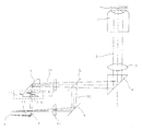
図1において、1は標本であり、2は標本1からの光を像面に至る観察光路0に導く対物レンズであり、3は対物レンズ2から出射された平行光線束を収束光線束に変換する結像レンズであり、4は結像レンズから出射された収束光線束を撮像装置側に反射するミラーもしくはプリズム等で構成された反射手段である。5は前記収束光線束を波長によって選択的に透過と反射に分離するダイクロイックミラーである。ここでは、ダイクロイックミラー5によって設定された特定の波長より長波長の光は透過して第1の収束光線束01を形成し、短波長の光は反射して第2の収束光線束02を形成する。61および62は、各々第1の収束光線01および第2の収束光線束02の中で各々の観察に供する波長帯のみを選択的に透過する特性を持った第1のフィルタおよび第2のフィルタである。7はダイクロイックミラー5を透過した第1の収束光線束01を反射する全反射プリズムで構成された第1の全反射手段であり、8はダイクロイックミラー5を反射した第2の収束光線束02を撮像装置9側に全反射する全反射ミラーで構成された第2の全反射手段である。10は第1の全反射手段7を反射した第1の収束光線束01を撮像装置9側に全反射すると共に、第2の全反射手段8を反射した第2の収束光線束02がその脇を通過する位置に配置された第3の全反射手段である。これら第1の全反射手段7、第2の全反射手段8、および第3の全反射手段10は、第1の収束光線束01および第2の収束光線束02の投影像を、撮像装置9の画角内の異なる位置で形成するように配置構成されている。13は、撮像装置9の画角内での第1の収束光線束01の投影像と第2の収束光線束02の投影像の重なりを防ぐための絞りである。11は、第1の収束光線束01中の第1の全反射手段7と第3の全反射手段の中間に設けられた光路長変換手段である。光路長変換手段11は、固定くさびプリズム11aと移動くさびプリズム11bから構成され、固定くさびプリズム11aと移動くさびプリズム11bは同一のくさび角度を有し、互いに対向する面同士が平行で且つその反対側の面は各々第1の収束光線束01の光軸と垂直になるように配置されている。また、移動くさびプリズム11bは、固定くさびプリズム11aに対向する面と平行な方向に移動可能に設けられている。なお、第1の全反射手段7に用いられる全反射プリズムと光路長変換手段11に用いられるくさびプリズム11aおよび11bの硝路長の合計は、第1の収束光線束01および第2の収束光線束02の焦点位置が撮像装置9において概ね合致するように設定されている。
In FIG. 1, 1 is a sample, 2 is an objective lens that guides the light from the
次に、本実施例の作用、効果について説明する。図2(a)および2(b)は、光路長変換手段11において、移動くさびプリズム11bを移動させた状態を示したものである。図2において、移動くさびプリズム11bを図2(a)の状態から図2(b)の状態へと移動させると、固定くさびプリズム11aと移動くさびプリズム11bを通る第1の収束光線束01の硝路長が変化する。また、移動くさびプリズム11bを図2(b)の状態から図2(a)の状態へと移動させた場合も同様である。ここで、固定くさびプリズム11aと移動くさびプリズム11bの間隔は常に一定であり、また第1の収束光線束01の光軸が固定くさびプリズム11aに入射する角度および移動くさびプリズム11bから出射する角度は常に垂直であるから、第1の収束光線束01の光軸は変化しない。光路長変換手段11における硝路長が増大すると、光路長の空気換算値が減小するため、第1の収束光線束01の焦点位置は撮像装置9を通り過ぎた先方に移動する。逆に、光路長変換手段11における硝路長が減小すると、光路長の空気換算値が増大するため、第1の収束光線束01の焦点位置は撮像装置9の手前に移動する。
Next, the operation and effect of the present embodiment will be described. 2 (a) and 2 (b) show a state in which the moving wedge prism 11b is moved in the optical path length conversion means 11. FIG. In FIG. 2, when the moving wedge prism 11b is moved from the state of FIG. 2 (a) to the state of FIG. 2 (b), the glass of the first
次に、移動くさびプリズム11bを意図的にずらした場合について図3により説明する。図3において対物レンズ2の焦点位置にある標本1上の面1aの投影像は、収束光線束02によって撮像装置9上に投影される。一方、移動くさびプリズム11bを意図的にずらして収束光線束01の光路長の空気換算値を変えた場合、収束光線束01の焦点位置は移動する。一方で、例えば収束光線束01の焦点位置を撮像装置9より距離Xだけ手前に移動し、この位置に標本面1aの像が投影されるようにした場合、この状態で撮像装置9上にある像点を対物レンズ2側に逆投影すると、その光線束は点線03で示されるような光路を経て対物レンズ2の焦点面である標本面1aより距離X/M2(Mは対物レンズ2の倍率)だけ対物レンズに近づいた1b上に投影される。言い換えれば、ダイクロイックミラー5を透過して光路長変換手段11を通る観察光路では、対物レンズ2の焦点位置より距離X/M2だけ近づいた位置にある標本面1bの像が撮像装置9上に投影される。
Next, a case where the moving wedge prism 11b is intentionally shifted will be described with reference to FIG. In FIG. 3, the projected image of the surface 1 a on the
以上のように、本実施例の構成によれば、撮像装置9の画角内の異なる位置に、標本1上の異なる高さの面の投影像を投影し、同時に観察することが可能となる。例えば、40倍の対物レンズを用い、カバーガラスに接着した細胞の内側1μmの位置に対物レンズ2の焦点を合わせた場合、像側の光路長を0.001×402=1.6mm長くすることで、カバーガラスの細胞接着面を投影することができる。本実施例の構成によれば、光路長変換手段11における硝路長を4.8mm(使用するガラスの屈折率を1.5とした場合)減らすことにより実現できる。
As described above, according to the configuration of the present embodiment, it is possible to project projected images of different heights on the
以上、本発明の第1の実施例について述べたが、この変形例として上記の光路長変換手段11のような連続的な補正手段の代わりに数種類の厚さの平行平面ガラス板を選択的に収束光線束中に挿入することによっても同様の成果を得られる。また、光分割手段はダイクロイックミラーに限定されず、ハーフミラーや偏光ビームスプリッタを使用してもよい。 As described above, the first embodiment of the present invention has been described. As a modified example, instead of continuous correction means such as the optical path length conversion means 11, several parallel plane glass plates with different thicknesses are selectively used. A similar result can be obtained by inserting into the convergent beam. The light splitting means is not limited to the dichroic mirror, and a half mirror or a polarization beam splitter may be used.
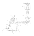
図4は本発明の第2の実施例の全体構成の概念図であり、図1における構成要素と同じものには同一の符号を付している。これらについては、その説明を省略する。 FIG. 4 is a conceptual diagram of the overall configuration of the second embodiment of the present invention. Components identical to those in FIG. Description of these will be omitted.
図4において、12は、第1の全反射手段7で反射された第1の結像光線束01を2回全反射して第3の全反射手段10に導くように構成した第4の全反射手段である。ここで、第4の全反射手段12は、第1の収束光線束01の光軸が入射側と出射側で平行になるように構成され、且つ第4の全反射手段12自体が第1の収束光線束の入射側および出射側の光軸と平行な方向に移動可能なように設けられている。14は、第1の結像光線束01の光路長の空気換算値を、第2の結像光線束と合わせるための透過プリズムである。
In FIG. 4,
次に、本実施例の作用、効果について説明する。図5は、第4の全反射手段12を移動させた状態(a)および(b)を示したものである。
図5(a)および(b)から分かるように、第4の全反射手段12を矢印の方向に移動させると第1の収束光線束01の硝路長が変化する。ここで、第4の全反射手段12の移動方向は、第1の収束光線束01の入射側および出射側の光軸と平行であるから、第1の収束光線束01の光軸は変化しない。図5(a)に示すように第4の全反射手段12を第1の全反射手段7に近づけると、光路長が減るため、第1の収束光線束01の焦点位置は撮像装置9を通り過ぎた先に移動する。また、図5(b)に示すように、逆に、第4の全反射手段12を第1の全反射手段7から遠ざけると、光路長が増えるため、第1の収束光線束01の焦点位置は撮像装置9の手前に移動する。
Next, the operation and effect of the present embodiment will be described. FIG. 5 shows the states (a) and (b) in which the fourth total reflection means 12 is moved.
As can be seen from FIGS. 5A and 5B, when the fourth total reflection means 12 is moved in the direction of the arrow, the glass path length of the first
次に第4の全反射手段12を意図的にずらした場合について図6により説明する。図6において対物レンズ2の焦点位置にある標本1上の面1aの投影像は、収束光線束02によって撮像装置9上に投影される。一方、第4の全反射手段12を意図的にずらして収束光線束01の光路長を変えた場合、例えば第4の全反射手段12を距離X/2だけ第1の全反射手段7から遠ざけた場合、収束光線束01の焦点位置は撮像装置9より距離Xだけ手前に移動し、この位置に標本面1aの像が投影される。一方、この状態で撮像装置9上にある像点を対物レンズ2側に逆投影すると、その光線束は点線03で示されるような光路を経て対物レンズ2の焦点面である標本面1aより距離X/M2(Mは対物レンズ2の倍率)だけ対物レンズに近づいた1b上に投影される。言い換えれば、ダイクロイックミラー5を透過して第4の全反射手段12を通る観察光路では、対物レンズ2の焦点位置より距離X/M2だけ近づいた位置にある標本面1bの像が撮像装置9上に投影される。
Next, the case where the fourth total reflection means 12 is intentionally shifted will be described with reference to FIG. In FIG. 6, the projected image of the surface 1 a on the
本実施例2の構成によれば、撮像装置9の画角内の異なる位置に、例えば、40倍の対物レンズを用い、カバーガラスに接着した細胞の内側1μmの位置に対物レンズ2の焦点を合わせた場合、像側の光路長を0.001×402=1.6mm長くすることで、カバーガラスの細胞接着面を投影することができる。本実施例の構成によれば、第4の全反射手段12を0.8mm移動させることにより実現できる。
According to the configuration of the second embodiment, for example, a 40 × objective lens is used at different positions within the angle of view of the
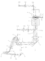
図7は本発明の第3の実施例の全体構成の概念図であり、図1乃至図6における構成要素と同じものには同一の符号を付している。これらについては、その説明を省略する。 FIG. 7 is a conceptual diagram of the overall configuration of the third embodiment of the present invention. The same components as those in FIGS. 1 to 6 are denoted by the same reference numerals. Description of these will be omitted.
図7において、21aは落射照明用の光源であり、22aは落射照明光の投影レンズである。25aは、落射照明光の特定の波長のみを透過する励起フィルタである。23aは励起フィルタ25aを透過した励起光を対物レンズ2側へ反射するダイクロイックミラーである。また、62は第2の収束光線束02中にあるフィルタであり、励起フィルタ25aを透過した波長帯の光によって励起される蛍光試薬の蛍光を選択的に透過するような特性を有するものである。21bはガラスファイバの出射端等によって構成される全反射蛍光照明用の光線出射部であり、22bは全反射照明光の投影レンズである。24は標本1を挟んで対物レンズ2と対向する位置に配置されたコンデンサレンズであり、全反射照明が可能な開口数を有する。23bは、全反射照明光をコンデンサレンズ24側へ反射するミラーである。
In FIG. 7, 21a is a light source for epi-illumination, and 22a is a projection lens for epi-illumination light. Reference numeral 25a denotes an excitation filter that transmits only a specific wavelength of epi-illumination light. Reference numeral 23a denotes a dichroic mirror that reflects the excitation light transmitted through the excitation filter 25a to the
ミラー23bを反射した全反射照明光はコンデンサレンズ24の前側焦点面上の光軸からずれた位置に集光され、コンデンサレンズ24を出射した後、標本1に対して全反射角より大きい角度で入射し、全反射する。標本1側には数100nm以下の深さでエバネッセント光のみが侵入し、励起光として利用される。一方、第1の収束光線束01中に設けられるフィルタ61は、エバネッセント光の波長帯の光によって励起される蛍光試薬の蛍光を選択的に透過するような特性を有するものを用いる。
The total reflection illumination light reflected from the mirror 23b is condensed at a position shifted from the optical axis on the front focal plane of the
次に、本実施例の作用、効果について説明する。落射照明の励起光によって励起された蛍光のうち、対物レンズ2の焦点位置にある標本1上の面1aから発光された蛍光の投影像は、収束光線束02によって撮像装置9上に投影される。一方、第4の全反射手段12をずらして収束光線束01の光路長を減らすことで、対物レンズ2の焦点位置より遠ざかった位置、即ち、コンデンサレンズ24に近づいた位置にある標本面1bの像を撮像装置9上に投影するようにする。光路長の減少量を調節して、標本面1bをコンデンサレンズ24側のカバーガラス面近傍に持ってくると、コンデンサレンズから入ったエバネッセント光による励起光が届くため、標本面1bから発光された蛍光の投影像は、収束光線束01によって撮像装置9上に投影される。
Next, the operation and effect of the present embodiment will be described. Of the fluorescence excited by the excitation light of the epi-illumination, a projection image of the fluorescence emitted from the surface 1a on the
以上のように、本実施例3の構成によれば、落射照明と全反射照明による2波長同時励起照明により、標本内部に対物の焦点位置を合わせて落射照明による詳細形状の観察を行いつつ、光路長変換による投影像をカバーガラス近傍に合わせて全反射照明による蛍光検出を行い、これらを一つの撮像装置で同時に撮像することができる。例えば、生細胞に観察において、細胞骨格付近におけるCa2+誘導蛋白の挙動の落射蛍光による観察と、細胞接着斑における開口放出に伴う発光の全反射蛍光による検出を同時に行う等、研究者の新たな要望に応え得る撮像装置を提供できる。 As described above, according to the configuration of the third embodiment, the two-wavelength simultaneous excitation illumination using the epi-illumination and the total reflection illumination is used to observe the detailed shape by the epi-illumination while aligning the focal position of the objective inside the sample. The projected image obtained by the optical path length conversion is matched with the vicinity of the cover glass to detect fluorescence by total reflection illumination, and these can be simultaneously imaged by one imaging device. For example, in the observation of living cells, the observation of Ca 2+ -induced protein behavior in the vicinity of the cytoskeleton by epifluorescence and the detection of luminescence associated with the opening emission in cell adhesion spots by total reflection fluorescence are performed simultaneously. It is possible to provide an imaging apparatus that can meet various needs.
以上、本発明の第3の実施例について述べたが、この変形例として図8に示すように、落射照明用光源21a、投影レンズ22aおよびミラー23bをコンデンサレンズ2の側に設け、エバネッセント光の浸みだし深さが異なる2種類の波長の全反射照明光をコンデンサレンズ24側から入射させることもできる。また、上記の全反射照明光をコンデンサレンズ24側ではなく、対物レンズ2側から入射するような構成にすることも可能である。このような構成によっても同様な効果を達成できる。
As described above, the third embodiment of the present invention has been described. As a modification, as shown in FIG. 8, the incident illumination light source 21a, the projection lens 22a, and the mirror 23b are provided on the
0、01、02、03 光線束
1 標本
2 対物レンズ
3 結像レンズ
4 ミラー
5 ダイクロイックミラー
7、8、10 全反射手段
9 撮像装置
11 光路長変換手段
11a 固定くさびプリズム
11b 移動くさびプリズム
13 絞り
14 透過プリズム
21a 落射照明用光源
21b 蛍光照明用光線射出部
22a、22b 投影レンズ
23a、23b ミラー
25a 励起フィルター
61、62 フィルター
X 焦点移動距離
0, 01, 02, 03
Claims (5)
前記対物レンズから像側に出射された平行光線束または収束光線束を撮像面で集光する収束光線束に変換する結像レンズと、
前記結像レンズより像側に配置されていて前記結像レンズによって変換された収束光線束を波長等の光学特性によって分割する分割手段と、
前記分割手段によって分割された各々の収束光線束の投影像を前記撮像面内の異なる位置で形成するように配置構成された全反射手段群と、
前記分割手段によって分割された各々の収束光線束のうち少なくとも一方の光路長または光路長の空気換算値を増減して該収束光線束の焦点位置を移動する光路長変換手段と、
を具備し、
前記標本上の異なる高さの面を同時に観察することを特徴とする顕微鏡の撮像光学系。 An objective lens that guides the light from the specimen to the observation optical path to the image plane;
An imaging lens that converts a parallel beam bundle or a convergent beam bundle emitted from the objective lens to the image side into a convergent beam bundle that is collected on the imaging surface ;
Dividing means for dividing the converging luminous flux is converted be disposed on the image side of the imaging lens by the imaging lens by the optical characteristic of the wavelength, etc.,
A total reflection means group arranged and formed so as to form projected images of the respective convergent beam bundles divided by the dividing means at different positions in the imaging surface ;
An optical path length conversion means for moving the focal position of the converging light beam by increasing or decreasing the air conversion value of at least one of the optical path length or optical path length of converging light bundle of each divided by the previous SL dividing means,
Equipped with,
An imaging optical system of a microscope characterized by simultaneously observing surfaces having different heights on the specimen .
前記対物レンズから像側に出射された平行光線束または収束光線束を撮像面で集光する収束光線束に変換する結像レンズと、An imaging lens that converts a parallel beam bundle or a convergent beam bundle emitted from the objective lens to the image side into a convergent beam bundle that is collected on the imaging surface;
前記結像レンズより像側に配置されていて前記結像レンズによって変換された収束光線束を波長等の光学特性によって分割する分割手段と、A dividing unit that is arranged on the image side of the imaging lens and divides the convergent light beam converted by the imaging lens according to optical characteristics such as a wavelength;
前記分割手段によって分割された各々の収束光線束の投影像を前記撮像面内の異なる位置で形成するように配置構成された全反射手段群と、A total reflection means group arranged and formed so as to form projected images of the respective convergent beam bundles divided by the dividing means at different positions in the imaging surface;
前記分割手段によって分割された各々の収束光線束のうち少なくとも一方の光路長または光路長の空気換算値を増減して該収束光線束の焦点位置を移動する光路長変換手段と、Optical path length conversion means for moving the focal position of the convergent light bundle by increasing or decreasing the optical path length of at least one of the convergent light bundles divided by the dividing means or an air-converted value of the optical path length;
前記異なる位置で形成された各々の投影像を前記撮像面で撮像する撮像装置と、An imaging device that captures images of the projected images formed at the different positions on the imaging surface;
を具備し、Comprising
前記標本上の異なる高さの面を同時に観察することを特徴とする顕微鏡。A microscope characterized by simultaneously observing surfaces of different heights on the specimen.
Priority Applications (1)
| Application Number | Priority Date | Filing Date | Title |
|---|---|---|---|
| JP2003273650A JP4454980B2 (en) | 2003-07-11 | 2003-07-11 | Microscope imaging optical system and microscope using the same |
Applications Claiming Priority (1)
| Application Number | Priority Date | Filing Date | Title |
|---|---|---|---|
| JP2003273650A JP4454980B2 (en) | 2003-07-11 | 2003-07-11 | Microscope imaging optical system and microscope using the same |
Publications (2)
| Publication Number | Publication Date |
|---|---|
| JP2005031589A JP2005031589A (en) | 2005-02-03 |
| JP4454980B2 true JP4454980B2 (en) | 2010-04-21 |
Family
ID=34210828
Family Applications (1)
| Application Number | Title | Priority Date | Filing Date |
|---|---|---|---|
| JP2003273650A Expired - Fee Related JP4454980B2 (en) | 2003-07-11 | 2003-07-11 | Microscope imaging optical system and microscope using the same |
Country Status (1)
| Country | Link |
|---|---|
| JP (1) | JP4454980B2 (en) |
Families Citing this family (7)
| Publication number | Priority date | Publication date | Assignee | Title |
|---|---|---|---|---|
| EP2081071A4 (en) * | 2006-11-30 | 2012-01-25 | Nikon Corp | Imaging device and microscope |
| JP2009186753A (en) * | 2008-02-06 | 2009-08-20 | Olympus Corp | Observation device |
| JP5389523B2 (en) * | 2009-04-30 | 2014-01-15 | オリンパス株式会社 | Optical microscope |
| DE102009060793A1 (en) * | 2009-12-22 | 2011-07-28 | Carl Zeiss Microlmaging GmbH, 07745 | High-resolution microscope and method for two- or three-dimensional position determination of objects |
| JP2014164097A (en) * | 2013-02-25 | 2014-09-08 | Olympus Corp | Beam splitter device, scanning observation device, laser scanning microscope and laser scanning endoscope |
| JP6236811B2 (en) | 2013-03-14 | 2017-11-29 | 株式会社リコー | Light source unit, illumination device, and image projection device |
| JP6349784B2 (en) | 2013-03-14 | 2018-07-04 | 株式会社リコー | Light source unit, illumination device, and image projection device |
-
2003
- 2003-07-11 JP JP2003273650A patent/JP4454980B2/en not_active Expired - Fee Related
Also Published As
| Publication number | Publication date |
|---|---|
| JP2005031589A (en) | 2005-02-03 |
Similar Documents
| Publication | Publication Date | Title |
|---|---|---|
| US5646411A (en) | Fluorescence imaging system compatible with macro and micro scanning objectives | |
| US8873046B2 (en) | Spectroscopic detection device and confocal microscope | |
| US5847400A (en) | Fluorescence imaging system having reduced background fluorescence | |
| JP6096814B2 (en) | Optical scanning microscope with spectral detection | |
| US9606342B2 (en) | Laser beam selectors | |
| JP5286774B2 (en) | Microscope device and fluorescent cube used therefor | |
| US8785885B1 (en) | Fluorescence imaging module | |
| JP2001272606A (en) | Illumination optical system and microscope provided with the same | |
| US7170676B2 (en) | Illumination switching apparatus and method | |
| US6917468B2 (en) | Confocal microscope | |
| US11333605B2 (en) | Sample measurement device and sample measurement method | |
| JP4454980B2 (en) | Microscope imaging optical system and microscope using the same | |
| US7315413B2 (en) | Illumination apparatus for microscope | |
| JP5495740B2 (en) | Confocal scanning microscope | |
| JP4086182B2 (en) | Spectroscope, confocal optical system using the same, and scanning optical microscope | |
| JP5623654B2 (en) | Confocal laser scanning microscope | |
| JP6696597B2 (en) | Light source device and distance measuring sensor including the same | |
| US9958661B2 (en) | Apparatus for structured illumination of a specimen | |
| US11874450B2 (en) | Oblique plane microscope for imaging a sample | |
| JP2007304103A (en) | Spectroscope and confocal optical system using it, and scanning optical microscope | |
| JP5726656B2 (en) | Disc scanning confocal observation device | |
| JP2005140956A (en) | Focal point detection device and fluorescent microscope | |
| JP5307868B2 (en) | Total reflection microscope | |
| JP2008164719A (en) | Scanning confocal microscope | |
| JP4593139B2 (en) | Optical scanning confocal observation device |
Legal Events
| Date | Code | Title | Description |
|---|---|---|---|
| A621 | Written request for application examination |
Free format text: JAPANESE INTERMEDIATE CODE: A621 Effective date: 20060706 |
|
| A131 | Notification of reasons for refusal |
Free format text: JAPANESE INTERMEDIATE CODE: A131 Effective date: 20090915 |
|
| A521 | Written amendment |
Free format text: JAPANESE INTERMEDIATE CODE: A523 Effective date: 20091009 |
|
| TRDD | Decision of grant or rejection written | ||
| A01 | Written decision to grant a patent or to grant a registration (utility model) |
Free format text: JAPANESE INTERMEDIATE CODE: A01 Effective date: 20100107 |
|
| A01 | Written decision to grant a patent or to grant a registration (utility model) |
Free format text: JAPANESE INTERMEDIATE CODE: A01 |
|
| A61 | First payment of annual fees (during grant procedure) |
Free format text: JAPANESE INTERMEDIATE CODE: A61 Effective date: 20100203 |
|
| FPAY | Renewal fee payment (event date is renewal date of database) |
Free format text: PAYMENT UNTIL: 20130212 Year of fee payment: 3 |
|
| R151 | Written notification of patent or utility model registration |
Ref document number: 4454980 Country of ref document: JP Free format text: JAPANESE INTERMEDIATE CODE: R151 |
|
| FPAY | Renewal fee payment (event date is renewal date of database) |
Free format text: PAYMENT UNTIL: 20130212 Year of fee payment: 3 |
|
| FPAY | Renewal fee payment (event date is renewal date of database) |
Free format text: PAYMENT UNTIL: 20140212 Year of fee payment: 4 |
|
| S531 | Written request for registration of change of domicile |
Free format text: JAPANESE INTERMEDIATE CODE: R313531 |
|
| R350 | Written notification of registration of transfer |
Free format text: JAPANESE INTERMEDIATE CODE: R350 |
|
| R250 | Receipt of annual fees |
Free format text: JAPANESE INTERMEDIATE CODE: R250 |
|
| LAPS | Cancellation because of no payment of annual fees |