JP4452182B2 - Printing cylinder support device, method of using printing cylinder support device, and printing machine provided with printing cylinder support device - Google Patents
Printing cylinder support device, method of using printing cylinder support device, and printing machine provided with printing cylinder support device Download PDFInfo
- Publication number
- JP4452182B2 JP4452182B2 JP2004533884A JP2004533884A JP4452182B2 JP 4452182 B2 JP4452182 B2 JP 4452182B2 JP 2004533884 A JP2004533884 A JP 2004533884A JP 2004533884 A JP2004533884 A JP 2004533884A JP 4452182 B2 JP4452182 B2 JP 4452182B2
- Authority
- JP
- Japan
- Prior art keywords
- printing cylinder
- bearing
- support
- printing
- support device
- Prior art date
- Legal status (The legal status is an assumption and is not a legal conclusion. Google has not performed a legal analysis and makes no representation as to the accuracy of the status listed.)
- Expired - Fee Related
Links
Images


Classifications
-
- B—PERFORMING OPERATIONS; TRANSPORTING
- B41—PRINTING; LINING MACHINES; TYPEWRITERS; STAMPS
- B41F—PRINTING MACHINES OR PRESSES
- B41F15/00—Screen printers
- B41F15/14—Details
- B41F15/34—Screens, Frames; Holders therefor
- B41F15/38—Screens, Frames; Holders therefor curved
-
- B—PERFORMING OPERATIONS; TRANSPORTING
- B41—PRINTING; LINING MACHINES; TYPEWRITERS; STAMPS
- B41F—PRINTING MACHINES OR PRESSES
- B41F13/00—Common details of rotary presses or machines
- B41F13/44—Arrangements to accommodate interchangeable cylinders of different sizes to enable machine to print on areas of different sizes
Description
本発明は、請求項1の前文に係る、印刷機用の印刷シリンダ支持装置に関する。
The present invention relates to a printing cylinder support device for a printing press according to the preamble of
そのような印刷シリンダ支持装置は、欧州特許出願公開第0864421A1号明細書から知られている。この欧州特許出願公開明細書は、交換可能なインク塗布手段を備えた印刷機を開示している。そのような印刷機は、いくつかの印刷装置を備え、この場合には、各印刷装置は、全印刷工程において別々の役割を果たす。そのような印刷装置は、異なるパターンのリピート長を有する、いくつかの異なるタイプの印刷に適し、また回転シルクスクリーン印刷、凹版印刷、凸版印刷およびフレキソ印刷などの様々な印刷技術に適する場合がある。印刷装置は、概ね印刷シリンダとインク塗布手段とを備える。作動状態では、印刷シリンダは、シリンダの表面上の描写線(被印刷物との接触線)に沿って接触する。インクは、印刷シリンダの内側へ、または直接外側へインク塗布手段により塗布される。 Such a printing cylinder support device is known from EP 0 844 421 A1. This published European patent application discloses a printing press with replaceable ink application means. Such a printing press comprises several printing devices, where each printing device plays a separate role in the entire printing process. Such printing devices are suitable for several different types of printing with different pattern repeat lengths and may be suitable for various printing technologies such as rotating silk screen printing, intaglio printing, letterpress printing and flexographic printing. . The printing apparatus generally includes a printing cylinder and ink application means. In the activated state, the printing cylinder contacts along a delineation line (contact line with the substrate) on the surface of the cylinder. Ink is applied to the inside of the printing cylinder or directly to the outside by ink application means.
印刷シリンダは、円周ベアリングシステム内に回転可能に載っており、この円周ベアリングシステムは、円形の軌道輪を半径方向に囲む3つのローラーからなる。前記軌道輪は、印刷シリンダの軸方向端部に同心に固定されている。3つのローラーに支持されるそのような軌道輪が、印刷シリンダの他方の端にも配置されている。3つのローラーの1つは、接触線の位置に配置されている。他方の2つのローラーは、印刷シリンダの他方の側に配置されている。 The printing cylinder is rotatably mounted in a circumferential bearing system, which consists of three rollers that radially surround a circular race. The race is fixed concentrically to the axial end of the printing cylinder. Such a bearing ring supported by three rollers is also arranged at the other end of the printing cylinder. One of the three rollers is arranged at the position of the contact line. The other two rollers are arranged on the other side of the printing cylinder.
先行技術では、印刷シリンダを交換可能である。印刷シリンダを交換する理由は、異なるパターンのリピート長の印刷をする必要がある場合であり、この目的のために直径が異なる印刷シリンダを使用することが好ましい。印刷技術を替えるために、印刷シリンダを交換することもできる。印刷シリンダを交換するためには、2つのローラーを、上述の特許明細書の図11に矢印Aにより概略を示した軌道に沿って外側へ移動させることができる。そのような軌道Aが、例えばローラーが旋回アームに回転可能に取り付けられていることにより生じ、この場合、旋回アームの旋回ピンは、必要に応じて、その全体を直線移動させ得ることが、実施により分かる。 In the prior art, the printing cylinder can be replaced. The reason for replacing the printing cylinder is when it is necessary to print with different patterns of repeat lengths, and for this purpose it is preferable to use printing cylinders with different diameters. It is also possible to replace the printing cylinder in order to change the printing technology. To replace the printing cylinder, the two rollers can be moved outwardly along the trajectory outlined by arrow A in FIG. 11 of the aforementioned patent specification. Such a trajectory A arises, for example, when the roller is rotatably mounted on the swivel arm, in which case the swivel pin of the swivel arm can be moved linearly as a whole as required. It understands.
この既知の印刷シリンダ支持装置には、大きな欠点がある。半径方向のエンクロージャ用のベアリングローラーの1つが、固定位置に配置され、その固定位置において、作動状態では基準ポイントで、軌道輪と接触する。この基準ポイントは、接触線に対して固定位置に配置されている。この固定ローラーの配置によって、異なる直径を有する印刷シリンダがなお、同じ接触線に沿って被印刷物と接触する。1つの固定ローラーが基準ポイントの位置にあることは、実際に、この必要な固定ローラーを無視しかつこのような固定ベアリングローラーのための空間が十分にない印刷機内において、既知の印刷シリンダ支持装置を非常に使用しにくくなることが判明した。その場合、既知の印刷シリンダ支持装置は、使用不可能である。この問題は、さらに固定ベアリングローラーを異なる位置にする手間をかけなければ解決できず、それは、そうすることで、接触線が、印刷シリンダのとり得る各直径に対する基準ポイント、したがってフレームに関連付けられた、異なる位置になるからである。これは、被印刷物が、シリンダの各直径のための、フレームに関連づけられた別の軌道に沿って動き、それによって、さらに複雑さが増し、よって高価になることを示している。 This known printing cylinder support device has major drawbacks. One of the bearing rollers for the radial enclosure is arranged in a fixed position, in contact with the track ring at the reference point in the operating state at the fixed position. This reference point is arranged at a fixed position with respect to the contact line. With this fixed roller arrangement, printing cylinders with different diameters still contact the substrate along the same contact line. The fact that one fixed roller is at the reference point is in fact a known printing cylinder support device in a printing machine that ignores this required fixed roller and does not have enough space for such a fixed bearing roller. It turned out to be very difficult to use. In that case, known printing cylinder support devices are not usable. This problem can only be resolved with the effort to place the fixed bearing rollers in different positions, so that the contact line is associated with a reference point for each possible diameter of the print cylinder, and thus the frame. This is because they are in different positions. This shows that the substrate moves along a separate trajectory associated with the frame for each diameter of the cylinder, thereby further increasing complexity and thus becoming expensive.
本発明の目的は、これらの欠点を少なくとも部分的に克服する印刷シリンダ支持装置を提供することであり、また使用可能な代案を提供することである。 It is an object of the present invention to provide a print cylinder support device that at least partially overcomes these drawbacks and to provide a usable alternative.
特に、本発明の目的は、印刷シリンダ支持装置であって、異なる直径の印刷シリンダおよび/または異なる印刷方法に迅速かつ容易に変更可能であるとともに、ベアリングローラーを基準ポイントの位置に配置する必要がない印刷シリンダ支持装置を提供することである。 In particular, it is an object of the present invention to provide a printing cylinder support device that can be quickly and easily changed to different diameter printing cylinders and / or different printing methods and that the bearing roller needs to be located at the reference point. There is no printing cylinder support device.
この目的は、本発明に係る請求項1に記載の印刷シリンダ支持装置によって達成される。この印刷シリンダ支持装置は、印刷シリンダの両方の軸方向端部に、前記印刷シリンダを回転可能に支持し得る支持フレームを備える。その目的のために、支持手段が、支持フレームに取り付けられる。前記支持手段は、作動状態において、印刷シリンダの表面上の描写線が被印刷物と接触するように配置される。この線は、接触線としても知られている。支持手段は、直径が異なる印刷シリンダを受け入れるのに適している。支持手段は、各軸方向端部のための少なくとも3つの支持ベアリングを含む。前記支持ベアリングは、ベアリングポイントの位置において、印刷シリンダの関連の端部に同心に取り付けられている軌道輪のベアリング表面と相互作用し、支持ベアリングが半径方向に印刷シリンダを囲むように、配置される。印刷シリンダ支持装置は、ベアリングポイントを移動線に沿って動かすように支持ベアリングを移動させ得る移動手段を備え、移動線は、支持フレームに対して方向が固定されている。支持ベアリングの位置は、連接手段により相互に連接されて、ベアリングポイントが常に共通の円上になる。装置自体はこの円を示さないので、この共通の円は、想像上のものである。上述の移動線と共通の円とは、基準ポイントにおいて相互に交差する。前記基準ポイントは、接触線からある間隔をおいて位置し、作動状態では、接触線と共通の円の中心点とにより形成された数学的な(想像上の)平面にある。作動状態では、共通の円と軌道輪のベアリング面とは、相互に一致する。したがって、作動状態における基準ポイントから接触線までの距離は、軌道輪のベアリング面から印刷シリンダ面までの最短距離と同一である。軌道輪として使用されるエンドリングでは、また本印刷技術に使用される印刷版では、これは、印刷版の直径に依存しない一定の距離である。
This object is achieved by a printing cylinder support device according to
ベアリングポイントが基準ポイントとともに前記共通の円上になるように、ベアリングポイントの移動線を方向付け、かつベアリングポイントの移動を連接することによって、直径が異なる印刷シリンダが、なお同じ接触線に沿って被印刷物と接触する。このために、ベアリングポイントの1つを基準ポイントの位置に配置する必要がなく、上述の先行技術の欠点が克服された。移動線は、直線であることが好ましく、また連接手段は、一定の比率に従って、各移動線に沿ってベアリングポイントの移動を連接する。直線の移動線に沿った移動によって、一実施形態では、移動を連接することが、一定の比率に従って行われることから、簡単になる。予想外の利点は、印刷シリンダが、直径に関係なく、常に、軌道輪の円周に沿ってほぼ同じ半径方向の(または角度)位置において支持されることである。各ベアリングポイントのための、また中心線から始まり接触線から遠くを向いている基準軸線から印刷シリンダの中心線の周りにおいて測定される最適の角度位置αを、選択可能である。 By directing the bearing point movement line and connecting the bearing point movement so that the bearing point is on the common circle with the reference point, the printing cylinders of different diameters still follow the same contact line. Contact the substrate. This eliminates the need to place one of the bearing points at the position of the reference point, overcoming the above-mentioned drawbacks of the prior art. The movement line is preferably a straight line, and the connecting means connects the movement of the bearing point along each movement line according to a certain ratio. By moving along a straight line of movement, in one embodiment, the movement is concatenated because it is performed according to a certain ratio. An unexpected advantage is that the print cylinder is always supported at approximately the same radial (or angular) position along the circumference of the race, regardless of diameter. An optimum angular position α can be selected for each bearing point and measured around the center line of the printing cylinder from a reference axis starting from the center line and pointing away from the contact line.
数学的にみれば、各ベアリングポイントが移動する直線の移動線の方向は、このベアリングポイントの選択された角度位置αであり、α/2に等しくなる。それらの線に沿った各ベアリングポイントの位置は、式d × cos(α/2)になり、この式で、値dは、各ベアリングポイントについて同一であり、そのモーメントにおいて相互にベアリングポイントにより描かれる共通の円の直径の値と等しい。 Mathematically, the direction of the straight line of movement that each bearing point travels is the selected angular position α of this bearing point, which is equal to α / 2. The position of each bearing point along those lines is the expression d × cos (α / 2), where the value d is the same for each bearing point and is drawn by the bearing points to each other at that moment. Is equal to the value of the diameter of the common circle.
一実施形態では、印刷シリンダ支持装置は、直線形の連接ロッドを備える。前記連接ロッドは、相互に支持ベアリングを連接する。支持ベアリングの1つの位置において、直線形の連接ロッドは、相互に固定連結されている。各連接ロッドは、このポイントから他の支持ベアリングの1つへ延びる。関連の連接ロッドは、滑動式に前記支持ベアリングに連結されている。滑動式の連接を行う位置において、連接ロッドは、支持ベアリングが移動する線と直角に交差している。 In one embodiment, the printing cylinder support device comprises a linear connecting rod. The connecting rods connect support bearings to each other. In one position of the support bearing, the linear connecting rods are fixedly connected to each other. Each connecting rod extends from this point to one of the other support bearings. The associated connecting rod is slidably connected to the support bearing. In the position where the sliding connection is made, the connecting rod intersects at right angles to the line on which the support bearing moves.
特に、支持ベアリングは、直線形の支持ベアリングガイドに沿って移動し、前記支持ベアリングガイドは、ベアリングポイントにより描かれる直線形の移動線と一致するかまたはそれと平行に延びている。 In particular, the support bearing moves along a linear support bearing guide, said support bearing guide extending along or parallel to the linear movement line drawn by the bearing points.
さらに詳細には、支持ベアリングガイドは、支持フレームの溝により形成され、その中に、連結部が滑動式に収容される。支持ベアリングは、この連結部に取り付けられている。直線形の連接ロッドを有する実施形態と組み合わせて、これらの連接ロッドは、前記連結部により滑動式に収容されることになる。 More specifically, the support bearing guide is formed by a groove in the support frame, in which the coupling part is slidably received. The support bearing is attached to the connecting portion. In combination with the embodiment with straight connecting rods, these connecting rods will be slidably received by the connecting part.
特に、印刷シリンダ支持装置は、印刷シリンダの各軸方向端部のための3つの支持ベアリングを具えて設計することができる。作動状態では、第1の支持ベアリングは、接触線の反対側の軌道輪に沿った位置に配置され、接触線から遠ざけまた近づけることができる。他の2つの支持ベアリングは、軌道輪のベアリング面に沿って測ってほぼ120°の半径方向の間隔で配置されている。軌道輪がどんな直径の場合でも支持ベアリングをこれらの位置にするためには、第2および第3の支持ベアリングのベアリングポイントを、接触線と、ベアリングポイントの共通の円の中心点とにより形成される数学的な(想像上の)平面に対して60°の角度を作る線に沿って移動させる必要があり、作動状態における中心点は、印刷シリンダの中心線上にある。ベアリングポイントが移動する線は、当然ながら、上述の数学的な平面に対して対称となっている。 In particular, the print cylinder support device can be designed with three support bearings for each axial end of the print cylinder. In the actuated state, the first support bearing is located at a position along the raceway opposite the contact line and can be moved away from or closer to the contact line. The other two support bearings are arranged at a radial spacing of approximately 120 ° as measured along the bearing surface of the race. In order for the bearings to be in these positions no matter the diameter of the race, the bearing points of the second and third bearings are formed by contact lines and the center point of the common circle of the bearing points. Must be moved along a line that makes an angle of 60 ° to the mathematical (imaginary) plane, and the center point in the operating state is on the center line of the printing cylinder. The line along which the bearing point moves is, of course, symmetric with respect to the mathematical plane described above.
特別な実施形態では、支持ベアリングは、ローラーまたはベアリングローラーの形態であり、これらは、作動状態において、装着された印刷版の軌道輪のベアリング面に沿って転動可能である。 In a special embodiment, the support bearings are in the form of rollers or bearing rollers, which in operation can roll along the bearing surface of the mounted printing plate raceway.
最後に、本発明は、請求項8に係る印刷シリンダ支持装置を有する印刷機の使用と、請求項9に係る印刷シリンダ支持装置を備えた印刷機とに関する。 Finally, the invention relates to the use of a printing press comprising a printing cylinder support device according to claim 8 and to a printing press comprising a printing cylinder support device according to claim 9.
本発明に係る好ましい実施形態の原理、および好ましい実施形態を、添付の図面に関してさらに詳細に説明する。 The principles of the preferred embodiment of the present invention and the preferred embodiment will be described in further detail with reference to the accompanying drawings.
これらの図面は、交換可能な印刷シリンダ1を示し、その表面2は、被印刷物3へのインク送り手段(図示せず)に適している。好ましい実施形態では、被印刷物3を印刷シリンダ1と圧胴4との間に挟み込む。印刷シリンダ1には、軌道輪が設けられ、そのベアリング面5の概略を両図面に示す。
These figures show a
印刷プロセス中に、被印刷物3を、回転している印刷シリンダ1に沿って運ぶ。本プロセスでは、被印刷物3が、表面2上の描写線、接触線6に沿って印刷シリンダ1に接している。印刷シリンダ1は、支持ベアリング11、12および13によって装着されており、これらベアリングは、好ましい実施形態では、ローラー11.1、12.1および13.1の形態である。支持ベアリング11、12および13、またはベアリングローラー11.1、12.1、13.1は、印刷シリンダの中心線Mから測定した軌道輪のベアリング面の半径、または直径DBの半分と等しい距離をおいて軌道輪のベアリング面5と接触している。支持ベアリング12は、軌道輪のベアリング面5に沿って角度α12に位置する。前記角度は、極座標系において定められ、その系において、Mは極であり、0軸は、基準軸7により定められ、この基準軸7は、接触線6から中心Mを通って延びている。この基準軸7の正の方向、したがってα=0は、軸7の端の矢印ポイントにより図1に示すように、被印刷物3のMから遠ざかる方向に定められている。それに対して、ベアリングポイント13は、軌道輪のベアリング面5に沿って角度α13に位置する。ベアリングポイント11は、正確に基準軸7上に位置して、その結果として、このベアリングポイントの角度α11は、ゼロになり、図示はできない。
During the printing process, the
印刷シリンダ1を交換する場合、支持ベアリングを点線21、22および23に沿って外側へ動かし、線21は、基準軸7と一致している。移動線21、22および23は、基準点25において相互に交差しており、図面には1/2×α12および1/2×α13と示したように、関連の支持ベアリングの値αの半分の角度と等しい角度に位置する。支持ベアリング11については、ここでもαの値がゼロであり、したがって、図面には図示不可能である。
When replacing the
任意のシリンダ直径DPを有する印刷シリンダ1を挿入中に、支持ベアリング11、12および13を線21、22および23に沿って内側へ動かして、関連の印刷シリンダ1の軌道輪のベアリング面5と接触させる。線21、22および23の位置決めおよび方向付けによって、支持ベアリング11、12および13は、印刷シリンダ1の直径DPと軌道輪のベアリング面5の直径DBとには無関係に、印刷シリンダ1の中心線に対して、最終的に常に同じ角度αに位置することになる。直径DPが異なる印刷シリンダの場合、先行技術では通常であるように、確実に、印刷シリンダ1の表面2の印刷面とベアリング面5との間の直径の同様の差を実際に維持することによって、印刷シリンダ1の接触線6が、結局支持フレームに対して同じ位置に、したがって、作動状態において被印刷物3および圧胴4に対して常に同じ位置になることが保証される。図1では、参照番号26が、表面2からベアリング面5までの距離を示しており、測定値26は、直径DPと直径DBとの間の差の半分である。
While inserting the
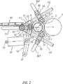
図2から図5に示す好ましい実施形態では、ベアリングローラー11.1、12.1および13.1の移動は、移動手段により案内され、移動手段は、直線形の溝21.1、22.1および23.1を含み、これらの溝は、支持またはベアリングフレーム27内に切り込まれ、フレーム27は、簡略化のため図2に示していない。これらの溝は、基準軸7に対してそれぞれ0°、60°、−60°の角度を形成している。これは、ベアリングローラー11.1、12.1および13.1が、常に、それぞれ、ベアリング面5の円周に沿って測定した0°、120°、および−120°の位置で、ベアリング面5と接触することを意味する。ピン30および31は、案内用の溝21.1、22.1および23.1内に収まっている。ピン31は、ベアリングローラー11.1、12.1および13.1用の軸32と一直線に配置されている。
In the preferred embodiment shown in FIGS. 2 to 5, the movement of the bearing rollers 11.1, 12.1 and 13.1 is guided by the moving means, which are linear grooves 21.1, 22.1. These grooves are cut into the support or bearing
溝21.1の位置において、ピン30および31は、実質的に三角形のプレート40により相互に連結されており、このプレート40は、ロッド42および43と固定連結されている。プレート40と、ロッド42および43とは、ベアリングポイントの動きをつなげる連接手段である。この目的のために、ロッド42および43は、溝22.1および23.1の場所におけるピン30と31との間の延長部と、前記ピン同士の間の連結部45との間を滑動するように収容される。
In the position of the
レバー50が、一方の端51をベアリングフレーム27に固定連結され、かつ他方の端を、ポイント51に沿って滑動するように、三角形のプレート40に固定連結されている。空気圧シリンダ55が、一方の端56を、ベアリングフレーム27にヒンジ式に連結され、他方の端57をロッド50にヒンジ式に連結されている。
The
平行に案内するための追加のラック60が、溝21.1に沿って設けられる。このように平行に案内することは、ロッド61と大歯車62とにより保証され、この大歯車62は、ラック61と噛み合い、ベアリングローラーは、印刷シリンダの2つの軸方向端部の同じ位置にある。圧胴4は、軸方向のベアリング70により圧胴フレーム71へ連結され、圧胴フレーム71は、簡略化のため図3にのみ示す。
An
図2から図5は、ローラーベアリング11.1、12.1および13.1により印刷シリンダ1が支持されている作動状態を示している。印刷シリンダ1の交換を可能にするために、空気圧シリンダ55が、レバー50を左に引き、その結果、ベアリングローラー11.1が、同様に左へ動く。同時に、ロッド42および43は、三角形のプレート40によってベアリングローラー11.1へ固定連結されているので、同様に左に動く。ローラーベアリング12.1用の溝22.1およびローラーベアリング13.1用の溝23.1の場所において、ロッド42および43のこの動きは、2つの方向へ分かれる。第1の方向は、ロッド42および43の長手方向軸線にあり、ロッド42、43は、ピン30と31との間と連結部45とを滑動する。動きの第2の成分は、溝22.1および23.1の方向の動きとなる。動きのこの成分によって、ピン30が押され、そして連結部45によって、同様に、外向きに、ピン31、軸32、ならびにベアリングローラー12.1および13.1も押される。この結果、印刷シリンダ1は、解放され、当業者に既知の方法で取り外すことができる。
2 to 5 show the operating state in which the
異なる直径DPの新しい印刷シリンダ1を挿入後、空気圧シリンダ55はレバー50を介して、印刷シリンダ1の軌道輪のベアリング面5に対してベアリングローラー11.1を移動させて、その結果、開口の方法と同様に、ベアリングローラー12.1および13.1が、同様にロッド42および43によりベアリング面5に押しつけられる。
After inserting a
ここに示し上述した好ましい実施形態とは異なる多くの実施形態および変形が可能である。例えば空気圧シリンダ55を、例えばスピンドルなどのドライブと交換可能であり、それにより、より大きな力をかけ得る。
Many embodiments and variations are possible that differ from the preferred embodiment shown and described above. For example, the
支持ベアリング同士の動きの連接は、さらに他の様々な設計にすることができる。例えば、直線ガイドの場合には、連接ロッドおよび溝に、ラックを設けることができ、その場合、滑動伝動部は、大歯車伝動部と替えるか、またはそれにより支持され得る。連接ロッドもまた、歯車、チェーンを介した伝動部、または例えばステッピングモータにより支持ベアリングが移動される場合は電子接続部などの、異なる形態の伝動部と交換可能である。直線ガイドと組み合わされるそのような代替タイプの伝動部の場合には、ガイドに沿った動きの伝動比を保証する必要がある。数式では、これらの比は、式d × cos(α/2)から導かれ、この式で、値αは、各ガイドにより異なり、全ベアリングポイントを通る共通の円の中心に対する、支持ベアリングポイントの角度位置に相当する。値dは、所与のモーメントにおいて全ガイドに対する式に常に同じ値をとる変数である。ベアリングポイントが前記ベアリング面に支持されている時の、dの値は、軌道輪のベアリング面の直径と等しくなる。dの値は、円周ベアリングシステムを開いている間、この直径より大きい。 The connection of movement between the support bearings can be in various other designs. For example, in the case of a linear guide, the connecting rods and grooves can be provided with racks, in which case the sliding transmission can be replaced by or supported by the large gear transmission. The connecting rod can also be replaced with a different form of transmission, such as a transmission through gears, a chain, or an electronic connection, for example when the support bearing is moved by a stepping motor. In the case of such an alternative type of transmission combined with a linear guide, it is necessary to ensure a transmission ratio of movement along the guide. In the formula, these ratios are derived from the formula d × cos (α / 2), where the value α is different for each guide and is the support bearing point's center to a common circle center through all bearing points. Corresponds to the angular position. The value d is a variable that always takes the same value in the equations for all guides at a given moment. The value of d when the bearing point is supported on the bearing surface is equal to the diameter of the bearing surface of the bearing ring. The value of d is greater than this diameter while opening the circumferential bearing system.
最後に、移動線は、湾曲させるなど、他のものにすることができる。例えば、これは、移動手段として旋回アームを利用した場合である。そのような非直線形の移動線のためには、上式における値αを一定にせず、考え得る機械的な連接手段の形状は、ベアリングポイントが共通の円上になることを保証するためにさらに複雑な形状になる。相互に電子接続されたステッピングモータが、これらの代替物である。 Finally, the movement line can be other, such as curved. For example, this is the case where a swivel arm is used as the moving means. For such non-linear movement lines, the value α in the above equation is not constant, and the shape of the possible mechanical connecting means is to ensure that the bearing points are on a common circle. It becomes a more complicated shape. Stepping motors that are electronically connected to each other are these alternatives.
Claims (9)
前記印刷シリンダは、作動状態において前記印刷シリンダ(1)の描写線と一致する接触線(6)に沿って被印刷物と接触するように設計され、
前記装置において、前記印刷シリンダ(1)は、異なる直径にすることができ、印刷シリンダ(1)の各軸方向端部のための前記支持手段は、少なくとも3つの支持ベアリング(11、12、13)を含み、各支持ベアリングは、ベアリングポイントの位置において、前記印刷シリンダ(1)に関連の端部に同心に取り付けられた軌道輪のベアリング面(5)と相互作用するように設計された前記印刷シリンダ支持装置において、
前記印刷シリンダ(1)の軸方向端部のための前記ベアリングポイントは、直径を変化させ得る共通の円上にあり、
前記印刷シリンダ支持装置は、前記支持フレーム(27)に対して位置を固定した移動線(21、22、23)に沿って前記ベアリングポイントが移動するように、前記支持ベアリング(11、12、13)を移動させるための移動手段(21.1、22.1、23.1)であって、前記移動線は、前記支持フレーム(27)に対して固定された基準ポイント(25)において相互に交差し、該基準ポイントは、同じ共通の円上にあり、作動状態において、前記接触線(6)と、前記共通の円の中心とにより画定される平面内にある前記移動手段を備え、
前記印刷シリンダ支持装置は、各移動線に沿って前記ベアリングポイントの移動を連接するための連接手段(40、42、43)を備えることを特徴とする印刷シリンダ支持装置。Printing cylinder support for a printing press comprising a supporting frame (27) and supporting means mounted on said supporting frame (27) for rotatably supporting one of several printing cylinders (1) A device,
The printing cylinder is designed to contact the substrate along a contact line (6) coinciding with the delineation line of the printing cylinder (1) in the operating state;
In the apparatus, the printing cylinder (1) can be of different diameters, and the support means for each axial end of the printing cylinder (1) comprises at least three support bearings (11, 12, 13). And each support bearing is designed to interact with the bearing surface (5) of the bearing ring concentrically mounted at the end associated with the printing cylinder (1) at the position of the bearing point. In the printing cylinder support device,
The bearing points for the axial ends of the printing cylinder (1) are on a common circle that can vary in diameter;
The printing cylinder support device includes the support bearings (11, 12, 13) such that the bearing points move along movement lines (21, 22, 23) whose positions are fixed with respect to the support frame (27). ) Moving means (21.1, 22.1, 23.1), the movement lines being mutually connected at a reference point (25) fixed relative to the support frame (27). Intersecting, the reference points are on the same common circle and, in the activated state, comprise the moving means in a plane defined by the contact line (6) and the center of the common circle;
The printing cylinder support device comprises connecting means (40, 42, 43) for connecting the movement of the bearing point along each movement line.
前記第2および第3の支持ベアリングのベアリングポイントを移動させる前記直線形の移動線は、前記平面に対して相互に対称となっており、かつ実質的に前記平面に対して60°の角度をなす請求項2から5のいずれかに記載の印刷シリンダ支持装置。Three linear bearings (11, 12, 13) for each axial end of the printing cylinder (1), said linear shape moving the bearing point of the first support bearing for each axial end. A movement line is substantially in a plane defined by the contact line (6) and the center of the common circle;
The linear movement lines for moving the bearing points of the second and third support bearings are mutually symmetric with respect to the plane and substantially at an angle of 60 ° with respect to the plane. The printing cylinder support device according to any one of claims 2 to 5.
所定の支持ベアリング(11)を移動線(21)に沿って印刷シリンダ(1)の軌道輪のベアリング面(5)から遠ざかる方向へ移動させることにより、他の支持ベアリング(12、13)を前記支持ベアリング(11)の移動に連動させて各移動線(22、23)に沿って移動させ、印刷シリンダ(1)を解放するステップと、By moving a predetermined support bearing (11) along the movement line (21) in a direction away from the bearing surface (5) of the bearing ring of the printing cylinder (1), the other support bearings (12, 13) are Moving along the movement lines (22, 23) in conjunction with the movement of the support bearing (11) and releasing the printing cylinder (1);
印刷シリンダ(1)を任意のシリンダ直径を有する他の印刷シリンダ(1)に交換するステップと、Replacing the printing cylinder (1) with another printing cylinder (1) having an arbitrary cylinder diameter;
所定の支持ベアリング(11)を移動線(21)に沿って印刷シリンダ(1)の軌道輪のベアリング面(5)の方向へ移動させることにより、他の支持ベアリング(12、13)を前記支持ベアリング(11)の移動に連動させて各移動線(22、23)に沿って移動させ、全ての支持ベアリング(11、12、13)を交換した印刷シリンダ(1)の軌道輪のベアリング面(5)に接触させるステップとを備える印刷シリンダ支持装置の使用方法。By moving a predetermined support bearing (11) along the movement line (21) in the direction of the bearing surface (5) of the bearing ring of the printing cylinder (1), the other support bearings (12, 13) are supported. The bearing surface of the bearing ring of the printing cylinder (1) in which all the support bearings (11, 12, 13) are exchanged by moving along the movement lines (22, 23) in conjunction with the movement of the bearing (11) ( 5) using the printing cylinder support device.
Applications Claiming Priority (2)
| Application Number | Priority Date | Filing Date | Title |
|---|---|---|---|
| NL1021417A NL1021417C2 (en) | 2002-09-09 | 2002-09-09 | Printing cylinder support unit. |
| PCT/NL2003/000627 WO2004022339A1 (en) | 2002-09-09 | 2003-09-09 | Printing cylinder supporting unit, use of printing cylinder supporting unit, and printing machine provided with printing cylinder supporting unit |
Publications (2)
| Publication Number | Publication Date |
|---|---|
| JP2005537955A JP2005537955A (en) | 2005-12-15 |
| JP4452182B2 true JP4452182B2 (en) | 2010-04-21 |
Family
ID=31973737
Family Applications (1)
| Application Number | Title | Priority Date | Filing Date |
|---|---|---|---|
| JP2004533884A Expired - Fee Related JP4452182B2 (en) | 2002-09-09 | 2003-09-09 | Printing cylinder support device, method of using printing cylinder support device, and printing machine provided with printing cylinder support device |
Country Status (8)
| Country | Link |
|---|---|
| US (1) | US7096783B2 (en) |
| EP (1) | EP1536948B1 (en) |
| JP (1) | JP4452182B2 (en) |
| CN (1) | CN100402287C (en) |
| AU (1) | AU2003263666A1 (en) |
| CA (1) | CA2495187C (en) |
| NL (1) | NL1021417C2 (en) |
| WO (1) | WO2004022339A1 (en) |
Families Citing this family (5)
| Publication number | Priority date | Publication date | Assignee | Title |
|---|---|---|---|---|
| NL1021417C2 (en) * | 2002-09-09 | 2004-03-10 | Stork Prints Bv | Printing cylinder support unit. |
| NL1021874C2 (en) * | 2002-11-08 | 2004-05-11 | Stork Prints Bv | Printing cylinder support unit with support ring. |
| NL1026736C2 (en) * | 2004-07-28 | 2006-01-31 | Stork Prints Bv | Printing cylinder support unit, positioning element, printing cylinder provided with positioning element, printing machine provided with printing cylinder support unit, and use thereof. |
| NL2002915C2 (en) * | 2009-05-22 | 2010-11-23 | Mps Holding B V | PRINTING MODULE AND PRINTING MACHINE PROVIDED WITH SUCH A PRINTING MODULE. |
| DE102011119088A1 (en) * | 2011-11-22 | 2013-05-23 | Gallus Druckmaschinen Gmbh | Flexographic printing unit with toggle lever system |
Family Cites Families (19)
| Publication number | Priority date | Publication date | Assignee | Title |
|---|---|---|---|---|
| US3183831A (en) * | 1961-07-31 | 1965-05-18 | Zimmer Franz Peter | Rotary printing machine |
| US3892176A (en) * | 1966-02-04 | 1975-07-01 | Konishiroku Photo Ind | Rotary screen tensioner for single sided drive |
| AT289856B (en) * | 1967-02-13 | 1971-05-10 | Peter Zimmer | Stencil recording |
| AT305940B (en) * | 1967-02-15 | 1973-03-26 | Zimmer Peter | Rotary stencil printing machine |
| US3986451A (en) * | 1972-02-09 | 1976-10-19 | Peter Zimmer | Screen holder mechanism for rotary screens |
| US3837277A (en) * | 1972-08-25 | 1974-09-24 | Precision Screen Machines | Fluid self-balancing rotary screen tensioning mount |
| DE2557247A1 (en) * | 1974-12-30 | 1976-07-01 | Johannes Zimmer | TEMPLATE RECORDING |
| DE3146255C2 (en) * | 1981-11-21 | 1985-11-21 | Mathias 4815 Schloß Holte-Stukenbrock Mitter | Device for storing and tensioning round stencils or screen cylinders |
| JPS5996984A (en) * | 1982-11-26 | 1984-06-04 | Riso Kagaku Corp | Stencil paper retaining device for printer |
| IT1212736B (en) * | 1983-05-04 | 1989-11-30 | Pirelli | DRIVE BELT. |
| DE3428668A1 (en) * | 1984-08-03 | 1986-02-13 | Heidelberger Druckmaschinen Ag, 6900 Heidelberg | DEVICE DRUM FOR SHEET PRINTING MACHINES, ESPECIALLY CARDBOARD MACHINES |
| US4909142A (en) * | 1986-11-19 | 1990-03-20 | American Screen Printing Equipment Corporation | Turntable mounting for automatic multi-color printing apparatus |
| DD283038A7 (en) * | 1988-06-10 | 1990-10-03 | Polygraph Leipzig | BEARING ARRANGEMENT |
| DE4241566A1 (en) * | 1992-12-10 | 1994-06-16 | Roland Man Druckmasch | Bearing for rotary press cylinder with sleeve and adjustable supports - allows restricted pivoting of levers to retract rollers from periphery of cylinder for fitting or removal of sleeve |
| IT1280075B1 (en) * | 1995-07-06 | 1997-12-29 | Omis Due Spa | SCREEN PRINTING MACHINE WITH ROTATING CYLINDRICAL SCREEN |
| NL1005525C2 (en) * | 1997-03-13 | 1998-09-15 | Multi Print Systems M P S B V | Printing machine with interchangeable ink applicators. |
| DE19803726B4 (en) * | 1998-01-30 | 2007-12-27 | Heidelberger Druckmaschinen Ag | Printing unit with a printing unit protection and an adjustable suspension for printing unit protection |
| NL1021417C2 (en) * | 2002-09-09 | 2004-03-10 | Stork Prints Bv | Printing cylinder support unit. |
| NL1021874C2 (en) * | 2002-11-08 | 2004-05-11 | Stork Prints Bv | Printing cylinder support unit with support ring. |
-
2002
- 2002-09-09 NL NL1021417A patent/NL1021417C2/en not_active IP Right Cessation
-
2003
- 2003-09-09 EP EP03794356.0A patent/EP1536948B1/en not_active Expired - Lifetime
- 2003-09-09 AU AU2003263666A patent/AU2003263666A1/en not_active Abandoned
- 2003-09-09 WO PCT/NL2003/000627 patent/WO2004022339A1/en active Application Filing
- 2003-09-09 CN CNB038213672A patent/CN100402287C/en not_active Expired - Fee Related
- 2003-09-09 JP JP2004533884A patent/JP4452182B2/en not_active Expired - Fee Related
- 2003-09-09 CA CA2495187A patent/CA2495187C/en not_active Expired - Fee Related
- 2003-09-09 US US10/527,288 patent/US7096783B2/en not_active Expired - Fee Related
Also Published As
| Publication number | Publication date |
|---|---|
| CA2495187C (en) | 2010-11-30 |
| JP2005537955A (en) | 2005-12-15 |
| AU2003263666A1 (en) | 2004-03-29 |
| WO2004022339A1 (en) | 2004-03-18 |
| EP1536948B1 (en) | 2013-07-24 |
| EP1536948A1 (en) | 2005-06-08 |
| US20050257703A1 (en) | 2005-11-24 |
| US7096783B2 (en) | 2006-08-29 |
| CN100402287C (en) | 2008-07-16 |
| CA2495187A1 (en) | 2004-03-18 |
| NL1021417C2 (en) | 2004-03-10 |
| CN1681655A (en) | 2005-10-12 |
Similar Documents
| Publication | Publication Date | Title |
|---|---|---|
| JP5701980B2 (en) | Self-aligning pivotable mandrel assembly | |
| US7398730B2 (en) | Printing cylinder support unit, positioning element, printing cylinder provided with positioning element, printing machine provided with printing cylinder support unit, and its use | |
| EP0320137A1 (en) | A laser engraving machine for preparing rotary screen printing screens | |
| GB2359518A (en) | Printing unit for a rotary printing machine | |
| ATE262466T1 (en) | POSITION ADJUSTABLE WEB FEED MECHANISM FOR A ROTARY PRINTING MACHINE | |
| JP3644717B2 (en) | Printing unit | |
| JP4452182B2 (en) | Printing cylinder support device, method of using printing cylinder support device, and printing machine provided with printing cylinder support device | |
| EP2524805A1 (en) | Ink wiping system for an intaglio printing press | |
| JP4632656B2 (en) | Printing cylinder support unit with support ring | |
| JP2004050829A (en) | Device for adjusting lateral registration to be used for printing apparatus of rotary press | |
| US6490969B2 (en) | Machine for printing or otherwise decorating hollow bodies | |
| US20060201351A1 (en) | Self-propelled imaging system | |
| US6945169B2 (en) | Apparatus for producing printing plates | |
| US4563949A (en) | Printing press | |
| US10286647B2 (en) | Processing unit and label printing machine having the processing unit | |
| JP3746818B2 (en) | Plate cylinder support device | |
| JP4570320B2 (en) | Method and apparatus for holding annular member | |
| WO2009143854A1 (en) | Axially displaceable roller in a printing unit | |
| JP2005028472A (en) | Wheel positioning device | |
| JP2019181769A (en) | Mandrel of sleeve type printing machine | |
| WO2004103707A1 (en) | Printing cylinder support unit for use in an offset printing press | |
| JPH07204967A (en) | Pallet shift mechanism in pallet shift device | |
| JP2006218878A (en) | Rotary press | |
| JPH01271243A (en) | Pressure apparatus of printing press |
Legal Events
| Date | Code | Title | Description |
|---|---|---|---|
| A621 | Written request for application examination |
Free format text: JAPANESE INTERMEDIATE CODE: A621 Effective date: 20060802 |
|
| A977 | Report on retrieval |
Free format text: JAPANESE INTERMEDIATE CODE: A971007 Effective date: 20090616 |
|
| A131 | Notification of reasons for refusal |
Free format text: JAPANESE INTERMEDIATE CODE: A131 Effective date: 20090624 |
|
| A521 | Written amendment |
Free format text: JAPANESE INTERMEDIATE CODE: A523 Effective date: 20090915 |
|
| TRDD | Decision of grant or rejection written | ||
| A01 | Written decision to grant a patent or to grant a registration (utility model) |
Free format text: JAPANESE INTERMEDIATE CODE: A01 Effective date: 20100106 |
|
| A01 | Written decision to grant a patent or to grant a registration (utility model) |
Free format text: JAPANESE INTERMEDIATE CODE: A01 |
|
| A61 | First payment of annual fees (during grant procedure) |
Free format text: JAPANESE INTERMEDIATE CODE: A61 Effective date: 20100129 |
|
| R150 | Certificate of patent or registration of utility model |
Free format text: JAPANESE INTERMEDIATE CODE: R150 |
|
| FPAY | Renewal fee payment (event date is renewal date of database) |
Free format text: PAYMENT UNTIL: 20130205 Year of fee payment: 3 |
|
| LAPS | Cancellation because of no payment of annual fees |