JP4443012B2 - Image generating apparatus, method and recording medium - Google Patents
Image generating apparatus, method and recording medium Download PDFInfo
- Publication number
- JP4443012B2 JP4443012B2 JP2000226933A JP2000226933A JP4443012B2 JP 4443012 B2 JP4443012 B2 JP 4443012B2 JP 2000226933 A JP2000226933 A JP 2000226933A JP 2000226933 A JP2000226933 A JP 2000226933A JP 4443012 B2 JP4443012 B2 JP 4443012B2
- Authority
- JP
- Japan
- Prior art keywords
- shadow
- terrain
- dimensional object
- dimensional
- image generation
- Prior art date
- Legal status (The legal status is an assumption and is not a legal conclusion. Google has not performed a legal analysis and makes no representation as to the accuracy of the status listed.)
- Expired - Fee Related
Links
Images


Classifications
-
- A63F13/10—
-
- A—HUMAN NECESSITIES
- A63—SPORTS; GAMES; AMUSEMENTS
- A63F—CARD, BOARD, OR ROULETTE GAMES; INDOOR GAMES USING SMALL MOVING PLAYING BODIES; VIDEO GAMES; GAMES NOT OTHERWISE PROVIDED FOR
- A63F13/00—Video games, i.e. games using an electronically generated display having two or more dimensions
- A63F13/50—Controlling the output signals based on the game progress
- A63F13/52—Controlling the output signals based on the game progress involving aspects of the displayed game scene
-
- A—HUMAN NECESSITIES
- A63—SPORTS; GAMES; AMUSEMENTS
- A63F—CARD, BOARD, OR ROULETTE GAMES; INDOOR GAMES USING SMALL MOVING PLAYING BODIES; VIDEO GAMES; GAMES NOT OTHERWISE PROVIDED FOR
- A63F13/00—Video games, i.e. games using an electronically generated display having two or more dimensions
- A63F13/45—Controlling the progress of the video game
-
- G—PHYSICS
- G06—COMPUTING; CALCULATING OR COUNTING
- G06T—IMAGE DATA PROCESSING OR GENERATION, IN GENERAL
- G06T15/00—3D [Three Dimensional] image rendering
- G06T15/50—Lighting effects
- G06T15/60—Shadow generation
-
- A—HUMAN NECESSITIES
- A63—SPORTS; GAMES; AMUSEMENTS
- A63F—CARD, BOARD, OR ROULETTE GAMES; INDOOR GAMES USING SMALL MOVING PLAYING BODIES; VIDEO GAMES; GAMES NOT OTHERWISE PROVIDED FOR
- A63F2300/00—Features of games using an electronically generated display having two or more dimensions, e.g. on a television screen, showing representations related to the game
- A63F2300/60—Methods for processing data by generating or executing the game program
- A63F2300/64—Methods for processing data by generating or executing the game program for computing dynamical parameters of game objects, e.g. motion determination or computation of frictional forces for a virtual car
-
- A—HUMAN NECESSITIES
- A63—SPORTS; GAMES; AMUSEMENTS
- A63F—CARD, BOARD, OR ROULETTE GAMES; INDOOR GAMES USING SMALL MOVING PLAYING BODIES; VIDEO GAMES; GAMES NOT OTHERWISE PROVIDED FOR
- A63F2300/00—Features of games using an electronically generated display having two or more dimensions, e.g. on a television screen, showing representations related to the game
- A63F2300/60—Methods for processing data by generating or executing the game program
- A63F2300/66—Methods for processing data by generating or executing the game program for rendering three dimensional images
- A63F2300/6646—Methods for processing data by generating or executing the game program for rendering three dimensional images for the computation and display of the shadow of an object or character
Description
【0001】
【発明の属する技術分野】
本発明は、画像生成装置、方法および記録媒体に関し、特に、仮想空間内に設定された3次元物体の影を表現する影オブジェクトを生成する画像生成装置、方法および記録媒体に関する。
【0002】
【従来の技術】
近年、コンピュータ・ゲーム等においてゲーム内の仮想空間にキャラクタ等の3次元物体を表示する場合、キャラクタの影を地形等に表示させることにより、一層現実感に富むゲームを実現している。従来、コンピュータ・ゲーム等においてキャラクタの影を表現する場合、円形等の簡単な形状で代用することにより影を表現する方法と、コンピュータ・ゲームの仮想的な空間内に所望の光源を設定し、この光源からの光がキャラクタ等に及ぼす影響をリアルタイムに計算して影を表現する方法とが知られている。
【0003】
前者の方法は、キャラクタの影を例えば円、楕円等の簡単な形状を用いて表現するため、コンピュータ(CPU)に対する負荷が軽いという利点があるが、キャラクタの動作の変化に対して自然な影を表現することが困難であるという問題があった。一方、後者の方法は、リアルタイムに光源からの光の影響を計算するため、緻密な影の表現ができるという利点があるが、CPUに対する負荷が重いという問題があった。
【0004】
キャラクタが脚部を有するような3次元物体であった場合、従来はキャラクタが脚部を開く等の動作があった場合でも、影の大きさ(スケール)は動作の前と後とで同じであった。さらに、キャラクタが腰部を有するような3次元物体であった場合、従来は腰部の直下に円形等の形状の影を表示していた。このため、キャラクタの動作に合わせた影の表現が困難であるという問題があった。
【0005】
【発明が解決しようとする課題】
そこで、本発明の目的は、上記問題を解決するためになされたものであり、キャラクタの動作の変化に対して自然な影を表現すると共に、CPUに対する負荷が軽い影を生成することができる画像生成装置、方法および記録媒体を提供することにある。
【0006】
さらに本発明の目的は、キャラクタが脚部を開く等の動作があった場合でもキャラクタの動作に合わせた躍動感のある影を生成することができる画像生成装置、方法および記録媒体を提供することにある。
【0007】
【課題を解決するための手段】
請求項1記載の発明の画像請生成装置は、仮想空間内に設定された3次元物体の影を表現する影オブジェクトを生成する画像生成装置であって、該3次元物体は該画像生成装置の画像表示部上に生成され、該3次元物体の動きは該画像生成装置の入力操作部からの入力により操作されるものであり、前記3次元物体の影オブジェクトが表示される地形オブジェクトと、前記地形オブジェクトに表示される影オブジェクトを前記3次元物体と該地形オブジェクトとの間の位置関係に応じて生成する影オブジェクト生成手段とを備え、前記影オブジェクト生成手段は、前記3次元物体と前記地形オブジェクトとが接している位置関係にある場合、影オブジェクトを該3次元物体の該地形オブジェクトに対する平行投影による影に基づいて生成し、前記3次元物体と前記地形オブジェクトとが接していない位置関係にある場合、該3次元物体と該地形オブジェクトとの間の距離が離れるほど影オブジェクトの透明度を高くし且つ前記平行投影による影を縮小させて生成し、該3次元物体と該地形オブジェクトとの間の距離が近づくほど影オブジェクトの透明度を低くして生成し且つ前記平行投影による影を拡大させて生成することを特徴とする。
【0012】
請求項2記載の発明の画像生成装置は、仮想空間内に設定された3次元物体の影を表現する影オブジェクトを生成する画像生成装置であって、該3次元物体は該画像生成装置の画像表示部上に生成され、該3次元物体の動きは該画像生成装置の入力操作部からの入力により操作されるものであり、前記3次元物体の影オブジェクトが表示される地形オブジェクトと、前記地形オブジェクトに表示される影オブジェクトを前記3次元物体と該地形オブジェクトとの間の位置関係に応じて生成する影オブジェクト生成手段とを備え、前記影オブジェクト生成手段は、前記3次元物体と前記地形オブジェクトとが接している位置関係にある場合、影オブジェクトを該3次元物体の該地形オブジェクトに対する平行投影による影に基づいて生成し、前記3次元物体と前記地形オブジェクトとが接していない位置関係にある場合、前記仮想空間内の所定の投影線の中心から投影された透視投影により影オブジェクトを生成することを特徴とする。
【0013】
請求項3記載の発明の画像生成装置は、仮想空間内に設定された3次元物体の影を表現する影オブジェクトを生成する画像生成装置であって、該3次元物体は該画像生成装置の画像表示部上に生成され、該3次元物体の動きは該画像生成装置の入力操作部からの入力により操作されるものであり、前記3次元物体の影オブジェクトが表示される地形オブジェクトと、前記地形オブジェクトに表示される影オブジェクトを前記3次元物体と該地形オブジェクトとの間の位置関係に応じて生成する影オブジェクト生成手段とを備え、前記影オブジェクト生成手段は、前記3次元物体と前記地形オブジェクトとが接している位置関係にある場合、影オブジェクトを該3次元物体の該地形オブジェクトに対する平行投影による影に基づいて生成し、前記3次元物体と前記地形オブジェクトとが接していない位置関係にある場合、該3次元物体と該地形オブジェクトとの間の距離が離れるのに応じて影オブジェクトを該平行投影による影よりも円形に補間して生成することを特徴とする。
【0014】
請求項4記載の発明の画像生成装置は、請求項1ないし3のいずれかににおいて、前記地形オブジェクトの法線と平行投影の投影線との間の角度が垂直ではない場合、前記影オブジェクト生成手段は該角度に応じて影オブジェクトを前記地形オブジェクト上に斜投影して生成し、かつ該角度が垂直に近づくほど影オブジェクトの透明度を高くすることができる。
【0019】
請求項5記載の発明の画像生成装置は、請求項1ないし4のいずれかににおいて、前記影オブジェクト生成手段は、前記3次元物体と前記地形オブジェクトとが接している位置関係にある場合、影オブジェクトの色を黒色で表示し、前記3次元物体と前記地形オブジェクトとが接していない位置関係にある場合、該3次元物体と該地形オブジェクトとの間の距離が離れるのに応じて影オブジェクトの色を該地形オブジェクトの色に近づけて表示することができる。
【0020】
請求項6記載の発明の画像生成装置は、請求項1ないし4のいずれかにおいて、前記影オブジェクト生成手段は、前記3次元物体と前記地形オブジェクトとが接している位置関係にある場合、影オブジェクトの色を該3次元物体の色で表示し、前記3次元物体と前記地形オブジェクトとが接していない位置関係にある場合、該3次元物体と該地形オブジェクトとの間の距離が離れるのに応じて影オブジェクトの色を黒色に近づけて表示することを特徴とする画像生成装置。
【0024】
請求項7記載の発明の画像生成装置は、請求項1ないし6のいずれかに記載の画像生成装置において、前記3次元物体が動作可能な少なくとも2つの基準となる基準脚を有し、該基準脚が動作した場合、前記基準脚が動作した後の該基準脚の先端間の幅を該基準脚が動作する前の該基準脚の先端間の幅で除した比を、前記影オブジェクト生成手段により生成された該基準脚が動作する前の基準となる影オブジェクトのスケールに乗じることにより、該基準脚が動作した後の影オブジェクトのスケールを求めるスケール決定手段と、所定の基準点を基にして前記スケール決定手段により求められたスケールを用いて影オブジェクトを生成する動作後影オブジェクト生成手段とをさらに備えることができる。
【0025】
請求項8記載の発明の画像生成装置は、請求項7において、前記3次元物体が前記基準脚の支点となる腰部を有する場合、前記所定の基準点は、前記地形オブジェクトに平行投影された前記腰部の投影点と前記少なくとも2つの基準脚の先端に対応する各投影点とに所定の重み付けをすることにより得ることができる。
【0026】
請求項9記載の発明の画像生成装置は、請求項1ないし8のいずれかにおいて、前記3次元物体が動作可能な少なくとも2つの基準となる基準脚を有する場合、前記位置関係は、該2つの基準脚の先端を結ぶ直線の中点と該地形オブジェクトとの間の位置関係とすることができる。
【0027】
請求項10記載の発明の画像生成方法は、仮想空間内に設定された3次元物体の影を表現する影オブジェクトを画像生成装置のコンピュータに生成させる画像生成方法であって、該3次元物体は該画像生成装置の画像表示部上に生成され、該3次元物体の動きは該画像生成装置の入力操作部からの入力により操作されるものであり、前記画像生成装置の影オブジェクト生成手段が、前記3次元物体の影オブジェクトが表示される地形オブジェクトに表示される影オブジェクトを前記3次元物体と該地形オブジェクトとの間の位置関係に応じて生成し、前記3次元物体と前記地形オブジェクトとが接している位置関係にある場合、影オブジェクトを該3次元物体の該地形オブジェクトに対する平行投影による影に基づいて生成し、前記3次元物体と前記地形オブジェクトとが接していない位置関係にある場合、該3次元物体と該地形オブジェクトとの間の距離が離れるほど影オブジェクトの透明度を高くし且つ前記平行投影による影を縮小させて生成し、該3次元物体と該地形オブジェクトとの間の距離が近づくほど影オブジェクトの透明度を低くして生成し且つ前記平行投影による影を拡大させて生成することを特徴とする。
【0030】
請求項11記載の発明の記録媒体は、仮想空間内に設定された3次元物体の影を表現する影オブジェクトを生成する画像生成方法を実行する画像生成装置のコンピュータが読み出し可能なプログラムを格納した記録媒体であって、該3次元物体は該画像生成装置の画像表示部上に生成され、該3次元物体の動きは該画像生成装置の入力操作部からの入力により操作されるものであり、前記画像生成装置の影オブジェクト生成手段が、前記3次元物体の影オブジェクトが表示される地形オブジェクトに表示される影オブジェクトを前記3次元物体と該地形オブジェクトとの間の位置関係に応じて生成し、前記3次元物体と前記地形オブジェクトとが接している位置関係にある場合、影オブジェクトを該3次元物体の該地形オブジェクトに対する平行投影による影に基づいて生成し、前記3次元物体と前記地形オブジェクトとが接していない位置関係にある場合、該3次元物体と該地形オブジェクトとの間の距離が離れるほど影オブジェクトの透明度を高くし且つ前記平行投影による影を縮小させて生成し、該3次元物体と該地形オブジェクトとの間の距離が近づくほど影オブジェクトの透明度を低くして生成し且つ前記平行投影による影を拡大させて生成する画像生成方法を実行するコンピュータが読み出し可能なプログラムを格納した記録媒体である。
【0033】
【発明の実施の形態】
以下、図面を参照して、まず本発明の画像生成装置について各実施の形態に共通する部分を説明し、次に本発明の各実施の形態を詳細に説明する。
【0034】
図1は、本発明の画像生成装置等の内部回路ブロックを示す。図1において、符号10は本発明の画像生成装置等の内部回路ブロック、1はコンピュータ・ゲーム等を実行する処理装置CPU(Central Processing Unit)、2は本発明の画像生成装置等の内部回路ブロック10の初期化等その他の処理に必要なデータが格納された読み出し専用記憶装置ROM(Read Only Memory)、3はCPU1が実行するコンピュータ・プログラムまたはデータが格納された読み書き可能な記憶装置RAM(Random Access Memory)、4は画像メモリとして用いられ後述の画像表示部6の少なくとも一画面分のデータ容量に相当する容量を有する記憶装置VRAM(Video RAM)、5はVRAM4のデータを画像データへ変換して画像表示部6へ送出する画像制御部、6はVRAM4から変換されて送出された画像データに基づいて画像を生成するディスプレイ等の画像表示部、7は本発明の画像生成方法等の実行により発生される音声を合成する音声合成部、8は音声合成部7に接続され音声を出力する音声出力部、11は本発明の画像生成方法等を実行するためのコンピュータ・プログラムまたはデータ等を記録したコンピュータ読み取り可能なCD−ROM(Compact Disc - Read Only memory)等の脱着可能な記録媒体をセットする記録媒体部、12はメモリ・カード等の脱着可能な記録媒体をセットする記録媒体部、9は記録媒体部11または12等と接続され入出力の制御を行う入出力制御部、14は本発明の画像生成装置等でコンピュータ・ゲームのプレイを行なうプレーヤが操作を行うコントローラ等の入力操作部、13は入力操作部14と接続され入力制御等を行う入力制御部、15はネットワーク(不図示)を介して外部のコンピュータ等と行なう通信を制御する通信制御部、14は上述のCPU1、ROM2、RAM3、VRAM4、音声合成部7、入出力制御部9、入力制御部13および通信制御部15を接続するバスである。
【0035】
本発明の画像生成方法等を実行するコンピュータ・プログラムおよびデータは記録媒体部11または12にセットされたCD−ROMまたはメモリ・カード等の記録媒体に記録させておくことができる。CD−ROMまたはメモリ・カード等の記録媒体に記録された上記コンピュータ・プログラムおよびデータは、入出力制御部9を介してバス14を通りRAM3へロードされる。CPU1はRAM3内にロードされた上記コンピュータ・プログラムを実行することにより、入力操作部14から入力制御部13を介してプレーヤによる入力が行なわれ、画像表示部6に実行中の画像が生成され、音声出力部8に実行中の音声を出力させることができる。
【0036】
図2は、本発明の画像生成装置の一実施の形態を示す。図2において、符号20は画像表示部16の一実施の形態であるディスプレイ、21は音声出力部8の一実施の形態であるスピーカ、51はディスプレイ20上に生成されたコンピュータ・ゲーム中のキャラクタ等の3次元物体(以下、固有の形状を有するキャラクタ等の3次元物体を特に指す場合はキャラクタ51等といい、一般的に3次元物体を指す場合は3次元物体51等と言う)、101はディスプレイ20上に生成された3次元物体51の影を表現する影オブジェクト、70は影オブジェクト101が表示される地形オブジェクト、22は後述の画像生成装置25とディスプレイ20との間を接続するケーブル、25は内部回路10を含む画像生成装置、23はCD−ROM等の記録媒体をセットする記録媒体部11を覆う蓋、26は蓋23を開けるためのボタンであって、このボタン26を押下して蓋23を開けて記録媒体をセットし、蓋23を押下して閉じることができる。続けて、符号24は画像生成装置25の電源ボタン、29は画像生成装置25と後述のコントローラ40との間を接続するケーブル、27、28等はコントローラ40と画像生成装置25とを接続する接続端子、40はプレイヤが操作する入力操作部14の一実施の形態であるコントローラである。図2では接続端子27、28等は4個示されており、ケーブル29はその内の接続端子27に接続されている。しかし、接続端子27等の数は4個に限定されるものではない。続けて、符号30は3次元物体51の動きを操作する方向キーであり、31は上方向へ移動させる上キー、32は右方向へ移動させる右キー、33は下方向へ移動させる下キー、34は左方向へ移動させる左キーであり、35はコンピュータ・ゲームを開始または一時停止させるスタート・キー、36、37、38および39はコンピュータ・ゲームの進行または3次元物体51のアクションを操作する等の機能を有するアクション・キーである。上方向キー31と左方向キー34とを同時に押下することにより、3次元物体51を左斜め上方向へ移動させることができる。他の方向キー31、32、33および34の組合せについても同様である。
【0037】
以下、本発明の各実施の形態について詳細に説明する。
実施の形態1.
【0038】
図3は、本発明の実施の形態1における影オブジェクトの生成例を示す。図3において、符号50、51は3次元物体、100は3次元物体50の影オブジェクト、101は3次元物体51の影オブジェクト、70は影オブジェクト100および101が表示される地形オブジェクトである。
【0039】
図3に示されるように、地形オブジェクト70は仮想空間におけるxy平面と平行な平面で表現され、3次元物体50は地形オブジェクト70上に接した状態、3次元物体51は仮想空間におけるz方向に浮いた状態で表現されている。影オブジェクト100または101は、3次元オブジェクト50または51と地形オブジェクト70との間の距離等の位置関係に応じて生成することができる(影オブジェクト生成手段)。例えば、3次元オブジェクト50は地形オブジェクト70と接しているため、その影オブジェクト100は図3に示されるように黒色で表現することができる。一方、3次元オブジェクト51は地形オブジェクト70の上方に浮いているため、その影オブジェクト101は透明度を高くして表現している。ここで透明度が高くなるということは地形オブジェクト70の有する色(不図示)が透けて見えてくるという意味である。このように、影オブジェクト101の透明度は3次元物体51が地形オブジェクト70から離れるにしたがって徐々に高くして表現し、3次元物体51と地形オブジェクト70とが近づくにしたがって低くして表現することができる。
【0040】
図3では、影オブジェクト101の濃度は周辺部へ行くほど薄くなるようにハッチングされている。しかし、影オブジェクト101全体を所望の濃度で均一に表現することもできる。本明細書において影オブジェクト101等の濃度を薄くすると言う場合は、特に明示しない限り上述の両方の場合を含むものとする。
【0041】
以上より、実施の形態1によれば、3次元物体と地形オブジェクトとが接している位置関係にある場合は影オブジェクトを黒色に生成することができ、接していない位置関係にある場合は3次元物体と地形オブジェクトとの間の距離が離れるのに応じて影オブジェクトの透明度を高くし近づくのに応じて透明度を低くして生成することができる。このため、3次元物体と地形オブジェクトとの間の距離に応じて自然な影を表現することができると共に、簡単な図形であることによりCPUに対する負荷が軽い影オブジェクトを生成することができる。
実施の形態2.
【0042】
図4(A)および(B)は、本発明の実施の形態2における影オブジェクトの生成例を示す。図4(A)および(B)で図3と同じ符号を付した個所は同じ要素を示すため説明は省略する。
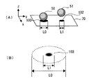
【0043】
図4(A)において、符号102は3次元物体51の実施の形態2における不透明に表現された影オブジェクト、L0は3次元物体50の影オブジェクトを平行投影に基づいて生成した場合の影オブジェクト100の直径等で代表されるスケール、L1は影オブジェクト102のスケールである。図4(A)に示されるように、実施の形態2では実施の形態1と同様に3次元オブジェクト51が地形オブジェクト70の上方に浮いている。上述の実施の形態1では3次元オブジェクト51の影オブジェクト101のスケールを影オブジェクト100のスケールと同一に表現した。しかし本実施の形態2では3次元オブジェクト51の影オブジェクト102のスケールL1を影オブジェクト100のスケールL0よりも縮小させて表現している。このように、影オブジェクト102のスケールL1を3次元物体51が地形オブジェクト70から離れるにしたがって徐々に縮小させて表現していくことができる。
【0044】
図4(B)は、3次元物体51の他の表現による影オブジェクト103を示す。図4(B)に示されるように、3次元オブジェクト51の影オブジェクト103のスケールL1を上述のように影オブジェクト100のスケールL0よりも小さく表現すると共に、実施の形態1の影オブジェクト101と同様に透明度を高くして表現することもできる。すなわち、影オブジェクト103のスケールL1を3次元物体51が地形オブジェクト70から離れるにしたがって徐々に小さく表現していくと共に、徐々に透明度を高くして表現していくことができる。影オブジェクト103は3次元物体51が地形オブジェクト70から離れるにしたがって計算して生成することもできるが、予め3次元物体51と地形オブジェクト70との間の距離に応じて生成しておき、段階的に予め生成しておいた影オブジェクト103を表示していくこともできる。
【0045】
以上より、実施の形態2によれば、3次元物体と地形オブジェクトとが接している位置関係にある場合は影オブジェクトを平行投影に基づくスケールで生成することができ、接していない位置関係にある場合は3次元物体と地形オブジェクトとの間の距離が離れるのに応じて影オブジェクトのスケールを減少させて生成することができる。さらにスケールと共に濃度を減少させて生成していくこともできる。このため、3次元物体と地形オブジェクトとの間の距離に応じて自然な影を表現することができると共に、簡単な図形であることによりCPUに対する負荷が軽い影オブジェクトを生成することができる。
実施の形態3.
【0046】
図5(A)および(B)は、本発明の実施の形態3における影オブジェクトの生成例を示す。図5(A)および(B)で図3と同じ符号を付した個所は同じ要素を示すため説明は省略する。
【0047】
図5(A)において、符号105は3次元物体51の実施の形態3における不透明に表現された影オブジェクト、L2は影オブジェクト105のスケール、80は仮想空間内に設定された点光源(所定の投影線の中心)である。図5(A)に示されるように、実施の形態3では実施の形態1と同様に3次元オブジェクト51がxy平面に平行な地形オブジェクト70の上方に浮いている。3次元物体50の影オブジェクト100は、z軸に平行な平行光線85による平行投影に基づいて生成される。上述の実施の形態2では3次元オブジェクト51の影オブジェクト102のスケールL1を影オブジェクト100のスケールL0よりも縮小させて表現した。しかし、本実施の形態3では地形オブジェクト70の上方に浮いている3次元オブジェクト51の影オブジェクト105を点光源(所定の投影線の中心)80からの透視投影により表現することができる。このため、影オブジェクト105のスケールL2を影オブジェクト100のスケールL0よりも拡大させて表現することができる。この結果、3次元物体51が地形オブジェクト70から離れるにしたがって影オブジェクト105のスケールL2を徐々に拡大させて表現していくことができる。
【0048】
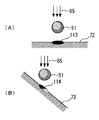
図5(B)において、符号72は平行光線85に対して垂直ではない角度の傾きを有する地形オブジェクト、87は地形オブジェクト72の法線、106は点光源80により地形オブジェクト72上に斜投影された影オブジェクトである。
【0049】
図5(B)に示されるように地形オブジェクト72の法線87が平行光線85に対して垂直ではない角度の傾きを有する場合であっても、3次元物体51の影オブジェクト106は点光源80からの斜投影により生成することができる。つまり、3次元物体51が地形オブジェクト72から離れるにしたがって影オブジェクト106のスケールL3を徐々に拡大させて表現していくことができる。
【0050】
以上より、実施の形態3によれば、3次元物体と地形オブジェクトとが接している位置関係にある場合は影オブジェクトを平行投影に基づくスケールで生成することができ、接していない位置関係にある場合は影オブジェクトを点光源からの透視投影により表現することができる。この結果、3次元物体が地形オブジェクトから離れるにしたがって、または3次元物体が点光源に近づくにしたがって影オブジェクトのスケールを徐々に拡大させて表現していくことができる。このため、3次元物体と地形オブジェクトとの間の距離に応じて自然な影を表現することができる。
実施の形態4.
【0051】
図6(A)および(B)は、本発明の実施の形態4における影オブジェクトの生成例を示す。図6(A)および(B)で図3と同じ符号を付した個所は同じ要素を示すため説明は省略する。
【0052】
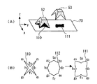
図6(A)において、符号52、53は3次元物体、110は3次元物体52の影オブジェクト、111は3次元物体53の影オブジェクトである。図6(A)に示されるように、実施の形態4では3次元オブジェクト52は地形オブジェクト70に接しており、3次元オブジェクト53は地形オブジェクト70の上方に浮いている。上述の実施の形態1ないし3では3次元オブジェクト50等が地形オブジェクト70に接している場合、3次元オブジェクト50等の影オブジェクトを簡単な楕円等の図形により表現していた。しかし、本実施の形態4では地形オブジェクト70に接している3次元オブジェクト52の影オブジェクト110を平行投影による影に基づいて生成することができる。このため、影オブジェクト110の形状を精緻に表現することができる。一方、地形オブジェクト70の上方に浮いている3次元オブジェクト53の影オブジェクト111は、影オブジェクト110と所望の多角形とを組み合わせることにより、円形に近い形状に補間して表示することができる。この結果、3次元物体52が地形オブジェクト70に接している場合は平行投影による精緻な影オブジェクト110により影を表現し、地形オブジェクト70から離れるにしたがって影オブジェクト111の形状を徐々に円形へ近づけて表現していくことができる。
【0053】
図6(B)は、上述の補間の方法を説明するための、図6(A)における影オブジェクト110および111のxy平面図を示す。図6(B)に示されるように、影オブジェクト110はa1ないしh1の8個の頂点を有しているものと想定する。次に上述の所望の多角形として、影オブジェクト110の頂点a1ないしh1に対応する同じ数の頂点a2ないしh2を有し、影オブジェクト110を含む円内の内接多角形112を考える。そこで影オブジェクト110と内接多角形112とを組み合わせ各頂点の補間を行うことにより、頂点a3ないしh3を有する影オブジェクト111を生成することができる。影オブジェクト111は、3次元物体53が地形オブジェクト70から離れるにしたがって計算して生成することもできるが、3次元物体53と地形オブジェクト70との間の距離に応じた影オブジェクト11等を予め複数個生成しておき、段階的に表示していくこともできる。さらに、上記の予め生成しておいた複数の影オブジェクト間で補間することにより、各段階で表示される影オブジェクトをさらに距離に応じて滑らかに表示することもできる。本実施の形態4の影オブジェクトの生成方法は、例えば複雑な形状を有するキャラクタが、地形オブジェクト70上に接地している状態からジャンプした場合等に有効な影オブジェクトの生成方法である。
【0054】
以上より、実施の形態4によれば、3次元物体が地形オブジェクトに接している場合は平行投影による精緻な影オブジェクトにより影を表現することができる。3次元物体が地形オブジェクトから離れるにしたがって、元の精緻な影オブジェクトと所望の多角形とを組み合わせて補間することにより、影オブジェクトの形状を徐々に円形へ近づけて表現していくことができる。このため、3次元物体と地形オブジェクトとの間の距離に応じて自然な影を表現することができると共に、簡単な図形であることによりCPUに対する負荷が軽い影オブジェクトを生成することができる。
実施の形態5.
【0055】
図7(A)および(B)は、本発明の実施の形態5における影オブジェクトの生成例を示す。図7(A)および(B)で図3と同じ符号を付した個所は同じ要素を示すため説明は省略する。
【0056】
図7(A)および(B)において、符号85は平行光線、72は平行光線85と垂直な地形オブジェクト、73は平行光線85と垂直ではない所望の角度を有する地形オブジェクト、113は3次元物体51の地形オブジェクト72に対する影オブジェクト、114は3次元物体51の地形オブジェクト73に対する影オブジェクトである。
【0057】
上述の各実施の形態1ないし4では、実施の形態3の一部を除き、図7(A)に示されるように地形オブジェクト72等は平行光線85と垂直であることを前提としていた。しかし、本実施の形態5では、図7(B)に示されるように地形オブジェクト73が平行光線85と垂直ではない所望の角度を有する場合、3次元物体51の影オブジェクト114を上記所望の角度に合わせて斜投影し傾けて生成することができる。この場合、地形オブジェクト73と平行光線85との間の角度が90度に近づくほど、すなわち地形オブジェクト72の傾きが垂直に近づくほど、影オブジェクト114の半透明度を高くすることができる。
【0058】
以上より、実施の形態5によれば、上述の各実施の形態に加えて、地形オブジェクトが平行光線と垂直ではない所望の角度を有する場合、3次元物体の影オブジェクトを上記所望の角度に合わせて斜投影し傾けて生成することができる。地形オブジェクトの傾きが垂直に近づくほど、影オブジェクトの半透明度を高くすることができる。このため、3次元物体と地形オブジェクトとの間の角度に応じて自然な影を表現することができる。
実施の形態6.
【0059】
図8は、本発明の実施の形態6における影オブジェクトの生成例を示す。図8で図3と同じ符号を付した個所は同じ要素を示すため説明は省略する。
【0060】
図8において、符号50は地形オブジェクト70に対して接していると共に静止している3次元物体、54は地形オブジェクト70に対して接していると共に移動している3次元物体、120は3次元物体54の影オブジェクトである。
【0061】
上述の各実施の形態1ないし5では、図8に示されるように3次元物体50は地形オブジェクト70等に対して静止していることを前提としていた。しかし、本実施の形態6では、図8に示されるように3次元物体54が地形オブジェクト70に対して所望の方向、たとえば仮想空間におけるy軸の負方向へ移動している場合、その影オブジェクト120の濃度を減少させて表現することができる。すなわち、静止している3次元物体50の影オブジェクト100は不透明として表現し、移動している3次元物体54の影オブジェクト120は濃度を減少させて表現することができる。上述の説明では、3次元物体50と54とは地形オブジェクトに接している場合を例にして説明したが、所望の距離だけ離れていてもよい。この場合、影オブジェクトの表現には上述の各実施の形態における表現方法を用いることができる。
【0062】
以上より、実施の形態6によれば、上述の各実施の形態に加えて、3次元物体が地形オブジェクトに対して静止している場合は影オブジェクトを不透明に生成し、3次元物体が地形オブジェクトに対して移動している場合は影オブジェクトの濃度を減少させて生成することができる。このため、3次元物体と地形オブジェクトとの間の速度に応じて自然な影を表現することができる。
実施の形態7.
【0063】
図9(A)、(B)および(C)は、本発明の実施の形態7における影オブジェクトの生成例を示す。図9(A)、(B)および(C)で図3と同じ符号を付した個所は同じ要素を示すため説明は省略する。
【0064】
図9(A)および(C)において、符号51は地形オブジェクト70から上方へ離れて静止状態にある3次元物体、122は3次元物体51の影オブジェクトであり、図9(B)において、55は地形オブジェクト70から上方へ離れていると共に移動状態にある3次元物体、123は3次元物体55の影オブジェクトである。図9(A)ないし(C)は最初静止していた3次元物体51が所望の方向、例えば仮想空間におけるy軸の負方向へ移動し、再び静止した過程を示している。
【0065】
上述の実施の形態6では、移動している3次元物体54の影オブジェクト120は濃度を減少させて表現した。しかし本実施の形態7では、所望の方向へ移動している3次元物体55の影を、影オブジェクト123のように移動している所望の方向へ移動した距離の分だけ引き伸ばして表現することができる。静止している3次元物体51の影オブジェクト122は不透明として表現し、移動している3次元物体55の影オブジェクト123は濃度を減少させて表現することができる。図9(B)に示された状態は実際には極めて短時間、例えば1/60秒間等であるため、不透明な影オブジェクト122を移動方向へ複数個表示していくよりも、躍動感のある影オブジェクトの表現を行うことができ、かつ表示のための処理負荷の少ない影オブジェクト123で表現することができる。
【0066】
以上より、実施の形態7によれば、静止している3次元物体51の影オブジェクト122は不透明として表現し、移動している3次元物体55の影オブジェクト123は濃度を減少させて表現することができる。このため、3次元物体と地形オブジェクトとの間の速度に応じてより自然な影を表現することができると共に、簡単な図形であることによりCPUに対する負荷が軽い影オブジェクトを生成することができる。
実施の形態8.
【0067】
図10(A)および(B)は、本発明の実施の形態8における影オブジェクトの生成例を示す。図10(A)および(B)で図3と同じ符号を付した個所は同じ要素を示すため説明は省略する。
【0068】
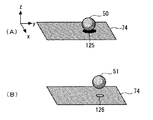
図10(A)、(B)において、符号74は所望の色(地色)を有する地形オブジェクト、125は地形オブジェクト74に接している3次元物体50の影オブジェクト、126は地形オブジェクト74から上方へ離れた状態にある3次元物体51の影オブジェクトである。図10(A)に示されるように、3次元物体50が地形オブジェクト74と接している場合は影オブジェクト125を黒色で表現し、3次元物体51が地形オブジェクト74と接していない場合は影オブジェクト126を地形オブジェクト74の地色に近づけて表現することができる。例えば地色が茶色であった場合、3次元物体51が地形オブジェクト74と接していない場合は影オブジェクト126の色を茶色に近づけて表現することができる。この結果、3次元物体51が地形オブジェクト74から離れるほど、その影オブジェクト126の色を地色に近づけて表現することができる。3次元物体50または51は、仮想空間のいずれかの方向、例えばy軸の負方向へ移動している状態であってもよい。
【0069】
以上より、実施の形態8によれば、3次元物体が地形オブジェクトと接している場合は影オブジェクトを黒色で表現し、3次元物体が地形オブジェクトと接していない場合は影オブジェクトを地形オブジェクトの地色に近づけて表現することができる。このため、3次元物体と地形オブジェクトとの間の距離に応じてより自然な影を表現することができる。
実施の形態9.
【0070】
図11は、本発明の実施の形態9における影オブジェクトの生成例を示す。図11で図3と同じ符号を付した個所は同じ要素を示すため説明は省略する。
【0071】
図11において、符号75は他の色を映しやすい地色、例えば白色の地色を有する地形オブジェクト、55は地形オブジェクト75に接している所望の色を有する3次元物体、130は3次元物体55の影オブジェクト、131は地形オブジェクト75から上方へ離れた状態にある3次元物体51の影オブジェクトである。
【0072】
図11に示されるように、所望の色を有する3次元物体55が他の色を映しやすい白色等の地色の地形オブジェクト75に接している場合、その影オブジェクト130の色を3次元物体55が有する所望の色と同じ色にすることができる。3次元物体51が地形オブジェクト75と接していない場合は、影オブジェクト131の色は黒色に近づけて表現することができる。この結果、3次元物体55の色が地形オブジェクト75に反映した状態を表現することができる。3次元物体55または51は、仮想空間のいずれかの方向、例えばy軸の負方向へ移動している状態であってもよい。
【0073】
以上より、実施の形態9によれば、所望の色を有する3次元物体が他の色を映しやすい白色等の地色の地形オブジェクトに接している場合、その影オブジェクトの色を3次元物体が有する所望の色と同じ色にすることができる。3次元物体が地形オブジェクトと接していない場合は、影オブジェクトの色は黒色に近づけて表現することができる。このため、3次元物体の有する色を地形オブジェクトに反映することができ、地形オブジェクトの地色に応じたより自然な影を表現することができる。
実施の形態10.
【0074】
図12は、本発明の実施の形態10における影オブジェクトの生成例を示す。図12で図3と同じ符号を付した個所は同じ要素を示すため説明は省略する。
【0075】
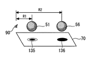
図12において、符号90は仮想空間内に設定された所定の視点、56は地形オブジェクト70から上方へ離れた状態にある3次元物体、135は3次元物体51の影オブジェクト、136は3次元物体56の影オブジェクト、R1は視点90と3次元物体51との間の距離、R2は視点90と3次元物体56との間の距離である。
【0076】
図12に示されるように、3次元物体51が視点90から所定の範囲内、例えば距離R1内にある場合はその影オブジェクト135は半透明で生成し、3次元物体56のように視点90から所定の範囲外、例えば距離R2の位置にある場合は、影オブジェクトの色を黒色で表示することができる。このため、視点90から近い3次元物体51ほど影オブジェクト135を半透明に表現し、視点90から遠くへ離れた3次元物体56ほど影オブジェクト136を黒色で表現することができる。
【0077】
以上より、実施の形態10によれば、3次元物体が視点から所定の範囲内にある場合はその影オブジェクトを半透明で生成し、3次元物体56のように視点90から所定の範囲外、例えば距離R2の位置にある場合は、影オブジェクトの色を黒色で表示することができる。このため、視点からの距離に応じたより自然な影を表現することができる。
実施の形態11.
【0078】
図13(A)および(B)は、本発明の実施の形態11における影オブジェクトの生成例を示す。図13(A)および(B)で図3または図12と同じ符号を付した個所は同じ要素を示すため説明は省略する。
【0079】
図13(A)において、符号76は視点90の周囲の環境、140は地形オブジェクト70から上方へ離れた状態にある3次元物体51の影オブジェクトであり、図13(B)において、符号77は3次元物体51の周囲の環境、141は3次元物体51の影オブジェクトである。
【0080】
図13(A)に示されるように、視点90の周囲の環境76が、例えばトンネル等のように暗い環境の場合、周囲の環境76の外部の比較的明るい状態にある3次元物体51の影オブジェクト140は、視点90から見て比較的明るく見えるような濃度、半透明度または色で表示することができる。一方、図13(B)に示されるように、3次元物体51の周囲の環境77が、例えばトンネル等のように暗い環境の場合、周囲の環境77の外部の比較的明るい状態にある視点90から見た3次元物体51の影オブジェクト141は、比較的暗く見えるような濃度、半透明度または色で表示することができる。
【0081】
以上より、実施の形態11によれば、3次元物体が置かれている周囲の環境の明暗の状況と視点が置かれている周囲の環境の明暗の状況とに応じて、影オブジェクトの濃度、半透明度または色で表現することができる。このため、視点と3次元物体とが置かれた周囲の環境に応じたより自然な影を表現することができる。
実施の形態12.
【0082】
図14は、本発明の実施の形態12における影オブジェクトの生成例を示す。図14において、符号156は所望の濃度の影オブジェクト、150、152および154は影オブジェクト156を構成する濃度の異なるピクセルである。ピクセル150、152および154は、この順に濃度が濃くなっている。
【0083】
上述の実施の形態1において、影オブジェクトを生成する場合、その濃度を周辺部に行くほど薄くなるように生成することができると説明した。その方法の例として、図14に示されるように、濃度の異なる複数のピクセル150、152および154等を用いて影オブジェクト156を生成する方法を用いることができる。すなわち、3次元オブジェクト51等が地形オブジェクト70等から所定の距離にある場合、周辺部にいくほど濃度が薄くなるようなピクセル150、152および154を有する影オブジェクト156を生成することができる。濃度はピクセル単位ではなくドット毎に設定していくこともできる。
【0084】
次に、影オブジェクトの濃度を周辺部に行くほど薄くなるように生成する他の方法の例を示す。まず、地形オブジェクトから所定の距離(H)にある3次元オブジェクトと影オブジェクト156等の濃度(C)との間の関係の例として、以下の式1または式2を考えることができる。
【0085】
【数1】
![]()
【数2】
![]()
式1または式2はあくまでも例示の式であって、これ以外の式を用いることができることはもちろんである。
【0088】
図15(A)は3次元物体が地形オブジェクトに接している場合(H=0)を示し、図15(B)は所望の距離Hにある場合を示す。図15(A)、(B)で符号160、162は各々地形オブジェクトとの距離が異なる影オブジェクト、Pは影オブジェクト160の中心となる点、Qは影オブジェクト160の頂点の1つである。
【0089】
本方法は、図15(A)に示されるように、まず上述の式1または式2で求められた距離Hに応じた濃度Aを影オブジェクト160の中心となる点および頂点Q等毎に求める。図15(A)は地形オブジェクトに接している場合であるため、濃度Aは各点において1.0となる。なお影オブジェクト160を黒色で示すと頂点P等が見えなくなるため黒色は省略してある。
【0090】
次に、所望の距離Hにある場合の濃度Aを上述の式1または式2を用いて求めると、濃度Aは例えば0.8となる。この濃度0.8を中心の点Pの濃度とし、頂点Q等の濃度を0.0とする。影オブジェクト162の濃度Aは中心の点Pの0.8から周辺の頂点Q等の0.0になるように徐々に薄く生成することができる。
【0091】
以上より、実施の形態12によれば、濃度の異なる複数のピクセルを用いて影オブジェクトを生成することができるので、3次元オブジェクトが地形オブジェクトから所定の距離にある場合、周辺部にいくほど濃度が薄くなるようなピクセル150、152および154を有する影オブジェクト156を生成することができる。
【0092】
実施の形態13.
上述の実施の形態において、3次元物体が少なくとも2つの脚(基準脚)を有している場合、例えば3次元物体が人等のキャラクタであり左右の脚を有している場合を考える。図16(A)、(B)、(C)および(D)は、本発明の実施の形態13における影オブジェクトの生成例を示す。図16(A)ないし(D)において、符号57は人等のキャラクタ、70はキャラクタ57が接して立っている地形オブジェクト、170、171は地形オブジェクト70上に表示されたキャラクタ57の影オブジェクトである。
【0093】
図16(A)に示されるように、Faはキャラクタ57が脚を閉じている場合の基本となる足幅(基準脚が動作する前の基準脚の先端間の幅)であり、Saはキャラクタ57が脚を閉じている場合の基本となる影オブジェクト170のスケール(基準となる影オブジェクトのスケール)である。ここで、キャラクタ57の脚が動作した場合、例えば脚を左右に開いた場合を考えると、図16(B)に示されるように、キャラクタ57がy軸方向に脚を開いた場合の足幅(基準脚が動作した後の基準脚の先端間の幅)はFbとなり、キャラクタ57が脚を開いた場合の影オブジェクト171のスケール(基準脚が動作した後の影オブジェクトのスケール)はSbのようになる。上述のSb、Sa、FaおよびFb間の関係は、以下の式3のように表すことができる(スケール決定手段)。
【0094】
【数3】
![]()
上述のようにして求められたSbを用いて、脚が動作した後の影オブジェクト171を生成することができる。影オブジェクト171は足幅方向(y軸方向)へ拡大するだけではなく、x軸方向へもy軸方向と同じ割合で拡大させている。影オブジェクト170または171は、腰の直下の基準点(所定の基準点)を基にして生成することもできるが、後述の実施の形態14で説明されるように、腰と左右の足とを用いて得られる基準点を基にして作成することができる(動作後影オブジェクト生成手段)。影オブジェクト171の濃度は影オブジェクト170よりも薄くしたり、半透明にしたりすることもできる。キャラクタ57は人を例に説明したが、犬や猫等の四足動物であってもよく、さらにムカデ等の多足類であってもよい。これらの場合は、特徴的な足を基準脚として選択することもできる。
【0096】
図16(C)および(D)は、キャラクタ57の脚の動作がxy平面上で行われた場合の、動作前の影オブジェクト170と動作後の影オブジェクト172とを示す。動作方向がy軸上で行われた場合ではなく、図16(D)に示されるように、x軸方向へキャラクタ57が左足を前に出すような動作が行われた場合でも同様に影オブジェクトのスケールSbを求めることができる。影オブジェクト170は動作方向(x軸方向)へ拡大するだけではなく、y軸方向へもx軸方向と同じ割合で拡大させている。もちろん、動作方向(x軸方向)のみへ拡大させることもできる。
【0097】
図17は、本発明の実施の形態13における動作後の影オブジェクトのスケールを求めるフローチャートを示す。
【0098】
図17に示されるように、まず基本となる足幅(Fa)を決定し(ステップS10)、基本となる影オブジェクトのスケール(Sa)を決定する(ステップS12)。次に、脚が動作した後の現在の足幅(Fb)を得る(ステップS14)。以上のデータから、脚が動作した後の現在の影オブジェクトのスケール(Sb)を式3を用いて決定する(ステップS16)。脚が動作した後の現在の影オブジェクトを表示するための上述の基準点を求める(ステップS18)。詳しくは次の実施の形態14で説明する。得られた基準点の対地高度(基準点の仮想空間におけるz座標)に応じて、スケールSbを適宜修正する(ステップS20)。これは上述の実施の形態で説明されたように、対地高度が大きくなるほど影オブジェクトのスケールを小さくすること等に対応する。光源に対して地表(地形オブジェクト)が傾きを有する場合は、その傾きに応じて影オブジェクトの濃度、半透明度等を変化させる(ステップS22)。最後に影を表示する(ステップS24)。
【0099】
以上より、実施の形態13によれば、上述の実施の形態に加えて、キャラクタが少なくとも2つの脚(基準脚)を有し、この脚を動作させた場合であっても、動作後の影オブジェクトのスケールを求め、所望の基準点に基づいて影オブジェクトを表示することができる。このため、キャラクタの動作に応じたより自然な影を表現することができる。
【0100】
実施の形態14.
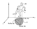
図18は、本発明の実施の形態14における影オブジェクトの生成例を示す。図18において、符号59は仮想空間内のキャラクタ、aはキャラクタ59の右脚の先端(右足)、bはキャラクタ59の左足、cはキャラクタ59の腰部、Pa(Xa,Ya)は右足aのxy平面上の投影点と座標、Pb(Xb,Yb)は左足bのxy平面上の投影点と座標、Pc(Xc,Yc)は腰部cのxy平面上の投影点と座標、Sはキャラクタ59の影オブジェクト、Gは影オブジェクトの基準点である。
【0101】
図18は例えば右足aと左足bとを閉じていた等の状態(不図示)から開くような動作を行ったあとの状態を示している。上述したように、影オブジェクトSは、腰部cの直下の投影点Pcを基にして生成することもできるが、本実施の形態14では、地形オブジェクト(xy平面)に平行投影された腰部cの投影点Pc、右足aに対応する投影点Paと左足bに対応する投影点Pbとに所定の重み付けをすることにより得られる基準点Gを基にして影オブジェクトSを作成することができる(動作後影オブジェクト生成手段)。基準点Gとしては、例えば投影点Pa、PbおよびPcの重心を用いることができる。しかし基準点は重心に限られるものではなく、適宜重み付けをすることにより各種の基準点を用いることもできる。
【0102】
以上より、実施の形態14によれば、地形オブジェクト(xy平面)に平行投影された腰部cの投影点Pc、右足aに対応する投影点Paと左足bに対応する投影点Pbとに所定の重み付けをすることにより得られる基準点Gを基にして影オブジェクトSを作成することができる。このため、腰部cの投影点Pcを基準点とする場合と比較して、キャラクタの動作に応じたより自然な影を表現することができる。
実施の形態15.
【0103】
上述した各実施の形態の機能を実現するコンピュータ・プログラムを記録した記録媒体を本発明の画像生成装置に供給し、その画像生成装置のコンピュータCPU51が記録媒体部60等にセットされた記録媒体に格納されたコンピュータ・プログラムを読み取り実行することによっても、本発明の目的が達成されることは言うまでもない。この場合、上述の記録媒体から読み取られたコンピュータ・プログラム自体が本発明の画像生成装置の新規な機能を実現することになり、そのコンピュータ・プログラムを記録した記録媒体は本発明を構成することになる。コンピュータ・プログラムを記録した記録媒体としては、例えば、CD−ROM、フロッピーディスク、ハードディスク、ROM、メモリカード、光ディスク等を用いることができる。
【0104】
以上より、実施の形態15によれば、上述した各実施の形態の機能を実現するコンピュータ・プログラムを記録した記録媒体を本発明の画像生成装置に供給し、その画像生成装置のコンピュータCPU11が記録媒体に格納されたコンピュータ・プログラムを読み取り実行することによっても、本発明の目的を達成することができる。
【0105】
上述した各実施の形態の機能を実現するコンピュータ・プログラムは、ネットワークを介して外部のコンピュータから配信させ通信制御部25を通して本発明の画像生成装置に供給させることもできる。
【0106】
【発明の効果】
以上説明したように、本発明の画像生成装置、方法および記録媒体によれば、3次元物体と地形オブジェクトとの位置関係、速度関係または視点等の周囲の環境に応じて、影オブジェクトの濃度、透明度またはスケールを変化させることにより、キャラクタの動作の変化に対して自然な影を表現すると共に、CPUに対する負荷が軽い影を生成できる画像生成装置、方法および記録媒体を提供することができる。
【0107】
さらに、動作後の影オブジェクトのスケールを求め、所望の基準点を基に影オブジェクトを生成することにより、キャラクタが脚部を開く等の動作があった場合でもキャラクタの動作に合わせた躍動感のある影を生成できる画像生成装置、方法および記録媒体を提供することができる。
【図面の簡単な説明】
【図1】 本発明の画像生成装置等の内部回路ブロックを示す図である。
【図2】 本発明の画像生成装置の一実施の形態を示す図である。
【図3】 本発明の実施の形態1における影オブジェクトの生成例を示す図である。
【図4】 本発明の実施の形態2における影オブジェクトの生成例を示す図である。
【図5】 本発明の実施の形態3における影オブジェクトの生成例を示す図である。
【図6】 本発明の実施の形態4における影オブジェクトの生成例を示す図である。
【図7】 本発明の実施の形態5における影オブジェクトの生成例を示す図である。
【図8】 本発明の実施の形態6における影オブジェクトの生成例を示す図である。
【図9】 本発明の実施の形態7における影オブジェクトの生成例を示す図である。
【図10】 本発明の実施の形態8における影オブジェクトの生成例を示す図である。
【図11】 本発明の実施の形態9における影オブジェクトの生成例を示す図である。
【図12】 本発明の実施の形態10における影オブジェクトの生成例を示す図である。
【図13】 本発明の実施の形態11における影オブジェクトの生成例を示す図である。
【図14】 本発明の実施の形態12における影オブジェクトの生成例を示す図である。
【図15】 本発明の実施の形態12における他の影オブジェクトの生成例を示す図である。
【図16】 本発明の実施の形態13における影オブジェクトの生成例を示す図である。
【図17】 本発明の実施の形態13における動作後の影オブジェクトのスケールを求めるフローチャートである。
【図18】 本発明の実施の形態14における影オブジェクトの生成例を示す図である。
【符号の説明】
10 内部回路ブロック、 1 CPU、 2 ROM、 3 RAM、 4VRAM、 5 画像制御部、 6 画像表示部、 7音声合成部、 8 音声出力部、 9 入出力制御部、 11,12 記録媒体部、 13 入力制御部、 14 入力操作部、 14 バス、 15 通信制御部、 20 ディスプレイ、 21 スピーカ、22,29 ケーブル、 23 蓋、 24 電源ボタン、 25 画像生成装置、 26 開閉ボタン、 27,28 接続端子、 30 方向キー、 31 上キー、 32 右キー、 33 下キー、 34 左キー、 35 スタート・キー、 36,37,38,39 アクション・キー、 30 コントローラ、 50,51,52,53,54,55,563次元物体、 57,59 キャラクタ、 70,72,74,75 地形オブジェクト、 76,77 環境、 80 光源、 83,85 光線、 87法線、 90 視点、 100,101,102,103,105,106,110,111,113,114,120,122,123,125,126,130,135,136,160,162,170,171 影オブジェクト、112 多角形、 150,152,154 ピクセル。[0001]
BACKGROUND OF THE INVENTION
The present invention relates to an image generation apparatus, method, and recording medium, and more particularly, to an image generation apparatus, method, and recording medium for generating a shadow object that represents a shadow of a three-dimensional object set in a virtual space.
[0002]
[Prior art]
In recent years, when a three-dimensional object such as a character is displayed in a virtual space within a game in a computer game or the like, a more realistic game has been realized by displaying the shadow of the character on the terrain or the like. Conventionally, when expressing the shadow of a character in a computer game or the like, a method of expressing the shadow by substituting a simple shape such as a circle, and setting a desired light source in the virtual space of the computer game, A method of expressing a shadow by calculating in real time the influence of light from a light source on a character or the like is known.
[0003]
The former method expresses the shadow of the character using a simple shape such as a circle, an ellipse, etc., and thus has the advantage of reducing the load on the computer (CPU). There was a problem that it was difficult to express. On the other hand, the latter method calculates the influence of light from the light source in real time, and thus has the advantage of being able to express a precise shadow, but has a problem that the load on the CPU is heavy.
[0004]
When the character is a three-dimensional object having legs, the shadow size (scale) is the same before and after the movement, even if the character has performed movements such as opening the legs. there were. Further, when the character is a three-dimensional object having a waist, conventionally, a shadow of a shape such as a circle has been displayed immediately below the waist. For this reason, there is a problem that it is difficult to express a shadow in accordance with the motion of the character.
[0005]
[Problems to be solved by the invention]
Accordingly, an object of the present invention has been made to solve the above-described problem, and an image that can generate a natural shadow with respect to a change in a character's motion and can generate a shadow with a light load on the CPU. An object is to provide a generation device, a method, and a recording medium.
[0006]
Furthermore, an object of the present invention is to provide an image generation apparatus, method, and recording medium capable of generating a shadow with a feeling of movement in accordance with the movement of the character even when the character performs an action such as opening a leg. It is in.
[0007]
[Means for Solving the Problems]
An image request generating device according to a first aspect of the present invention is an image generating device that generates a shadow object that expresses a shadow of a three-dimensional object set in a virtual space, The three-dimensional object is generated on the image display unit of the image generation device, and the movement of the three-dimensional object is operated by an input from the input operation unit of the image generation device, A terrain object on which the shadow object of the three-dimensional object is displayed; and a shadow object generating means for generating a shadow object displayed on the terrain object according to a positional relationship between the three-dimensional object and the terrain object. Preparation The shadow object generating means generates a shadow object based on a shadow obtained by parallel projection of the three-dimensional object with respect to the terrain object when the three-dimensional object and the terrain object are in contact with each other; When the 3D object and the terrain object are not in contact with each other, the transparency of the shadow object is increased and the shadow by the parallel projection is reduced as the distance between the 3D object and the terrain object increases. Generated by reducing the transparency of the shadow object as the distance between the three-dimensional object and the terrain object decreases, and expanding the shadow by the parallel projection. .
[0012]
[0013]
[0014]
[0019]
[0020]
Claim 6 The image generation apparatus according to the invention described in
[0024]
[0025]
[0026]
Claim 9 The image generation apparatus according to the invention described in
[0027]
[0030]
[0033]
DETAILED DESCRIPTION OF THE INVENTION
Hereinafter, with reference to the drawings, first, the parts common to the respective embodiments of the image generating apparatus of the present invention will be described, and then the respective embodiments of the present invention will be described in detail.
[0034]
FIG. 1 shows an internal circuit block of the image generating apparatus of the present invention. In FIG. 1,
[0035]
The computer program and data for executing the image generation method of the present invention can be recorded on a recording medium such as a CD-ROM or a memory card set in the
[0036]
FIG. 2 shows an embodiment of the image generation apparatus of the present invention. In FIG. 2,
[0037]
Hereinafter, each embodiment of the present invention will be described in detail.
[0038]
FIG. 3 shows a generation example of a shadow object in
[0039]
As shown in FIG. 3, the
[0040]
In FIG. 3, the density of the
[0041]
As described above, according to the first embodiment, the shadow object can be generated in black when the three-dimensional object and the terrain object are in contact with each other, and the three-dimensional object can be generated in the non-contact position. It can be generated by increasing the transparency of the shadow object as the distance between the object and the terrain object increases and decreasing the transparency as it approaches. Therefore, it is possible to express a natural shadow according to the distance between the three-dimensional object and the terrain object, and it is possible to generate a shadow object that has a light load on the CPU due to a simple graphic.
[0042]
4A and 4B show an example of generation of a shadow object in
[0043]
In FIG. 4A,
[0044]
FIG. 4B shows a
[0045]
As described above, according to the second embodiment, when a three-dimensional object and a terrain object are in contact with each other, a shadow object can be generated on a scale based on parallel projection and is in a position relationship that is not in contact. In this case, the shadow object can be generated by reducing the scale of the shadow object as the distance between the three-dimensional object and the terrain object increases. Furthermore, the density can be reduced along with the scale. Therefore, it is possible to express a natural shadow according to the distance between the three-dimensional object and the terrain object, and it is possible to generate a shadow object that has a light load on the CPU due to a simple graphic.
[0046]
5A and 5B show an example of generation of a shadow object in the third embodiment of the present invention. 5A and 5B, the same reference numerals as those in FIG. 3 indicate the same elements, and the description thereof is omitted.
[0047]
In FIG. 5A,
[0048]
In FIG. 5B,
[0049]
As shown in FIG. 5B, the
[0050]
As described above, according to the third embodiment, when the three-dimensional object and the terrain object are in contact with each other, the shadow object can be generated on a scale based on parallel projection, and is in a position relationship that is not in contact. In this case, the shadow object can be expressed by perspective projection from a point light source. As a result, the scale of the shadow object can be gradually expanded as the 3D object moves away from the terrain object or the 3D object approaches the point light source. Therefore, a natural shadow can be expressed according to the distance between the three-dimensional object and the terrain object.
[0051]
6A and 6B show an example of generation of a shadow object in the fourth embodiment of the present invention. In FIGS. 6A and 6B, the portions denoted by the same reference numerals as those in FIG.
[0052]
In FIG. 6A,
[0053]
FIG. 6B is an xy plan view of the shadow objects 110 and 111 in FIG. 6A for explaining the above-described interpolation method. As shown in FIG. 6B, it is assumed that the
[0054]
As described above, according to the fourth embodiment, when a three-dimensional object is in contact with a terrain object, a shadow can be expressed by a precise shadow object by parallel projection. As the three-dimensional object moves away from the terrain object, the original fine shadow object and the desired polygon are combined and interpolated, so that the shape of the shadow object can be gradually approximated to a circle. Therefore, it is possible to express a natural shadow according to the distance between the three-dimensional object and the terrain object, and it is possible to generate a shadow object that has a light load on the CPU due to a simple graphic.
[0055]
FIGS. 7A and 7B show a generation example of a shadow object in the fifth embodiment of the present invention. In FIGS. 7A and 7B, the same reference numerals as those in FIG.
[0056]
7A and 7B,
[0057]
In the above-described first to fourth embodiments, except for a part of the third embodiment, it is assumed that the
[0058]
As described above, according to the fifth embodiment, in addition to the above-described embodiments, when the terrain object has a desired angle that is not perpendicular to the parallel rays, the shadow object of the three-dimensional object is adjusted to the desired angle. Can be generated by oblique projection and tilting. As the inclination of the terrain object becomes closer to the vertical, the translucency of the shadow object can be increased. Therefore, a natural shadow can be expressed according to the angle between the three-dimensional object and the terrain object.
Embodiment 6 FIG.
[0059]
FIG. 8 shows a generation example of a shadow object in the sixth embodiment of the present invention. In FIG. 8, the parts denoted by the same reference numerals as those in FIG.
[0060]
In FIG. 8,
[0061]
In each of the above-described first to fifth embodiments, it is assumed that the three-
[0062]
As described above, according to the sixth embodiment, in addition to the above-described embodiments, when the three-dimensional object is stationary with respect to the terrain object, the shadow object is generated opaquely, and the three-dimensional object is converted into the terrain object. Can be generated by reducing the density of the shadow object. For this reason, a natural shadow can be expressed according to the speed between the three-dimensional object and the terrain object.
[0063]
FIGS. 9A, 9B, and 9C show examples of generating shadow objects according to the seventh embodiment of the present invention. In FIGS. 9A, 9B, and 9C, the portions denoted by the same reference numerals as those in FIG.
[0064]
9A and 9C,
[0065]
In the above-described sixth embodiment, the
[0066]
As described above, according to the seventh embodiment, the
[0067]
FIGS. 10A and 10B show examples of generation of shadow objects in the eighth embodiment of the present invention. In FIGS. 10A and 10B, the same reference numerals as those in FIG.
[0068]
In FIGS. 10A and 10B,
[0069]
As described above, according to the eighth embodiment, when a three-dimensional object is in contact with the terrain object, the shadow object is expressed in black, and when the three-dimensional object is not in contact with the terrain object, the shadow object is It can be expressed close to the color. Therefore, a more natural shadow can be expressed according to the distance between the three-dimensional object and the terrain object.
Embodiment 9 FIG.
[0070]
FIG. 11 shows a generation example of a shadow object in the ninth embodiment of the present invention. In FIG. 11, the parts denoted by the same reference numerals as those in FIG.
[0071]
In FIG. 11,
[0072]
As shown in FIG. 11, when a three-
[0073]
As described above, according to the ninth embodiment, when a three-dimensional object having a desired color is in contact with a terrain object having a ground color such as white that easily reflects other colors, the color of the shadow object is determined by the three-dimensional object. It can be the same color as the desired color. When the three-dimensional object is not in contact with the terrain object, the color of the shadow object can be expressed close to black. Therefore, the color of the three-dimensional object can be reflected on the terrain object, and a more natural shadow corresponding to the ground color of the terrain object can be expressed.
[0074]
FIG. 12 shows a generation example of a shadow object in the tenth embodiment of the present invention. In FIG. 12, the parts denoted by the same reference numerals as those in FIG.
[0075]
In FIG. 12,
[0076]
As shown in FIG. 12, when the three-
[0077]
As described above, according to the tenth embodiment, when a three-dimensional object is within a predetermined range from the viewpoint, the shadow object is generated semi-transparently and out of the predetermined range from the
[0078]
FIGS. 13A and 13B show a generation example of a shadow object in the eleventh embodiment of the present invention. In FIGS. 13A and 13B, the portions denoted by the same reference numerals as those in FIG. 3 or FIG.
[0079]
In FIG. 13A,
[0080]
As shown in FIG. 13A, when the
[0081]
As described above, according to the eleventh embodiment, the density of the shadow object according to the light / dark situation of the surrounding environment where the three-dimensional object is placed and the light / dark situation of the surrounding environment where the viewpoint is placed, It can be expressed by translucency or color. For this reason, a more natural shadow according to the surrounding environment where the viewpoint and the three-dimensional object are placed can be expressed.
[0082]
FIG. 14 shows a generation example of a shadow object according to the twelfth embodiment of the present invention. In FIG. 14,
[0083]
In the first embodiment described above, it has been described that when a shadow object is generated, the density can be generated so as to decrease toward the periphery. As an example of the method, as shown in FIG. 14, a method of generating a
[0084]
Next, an example of another method for generating the shadow object so as to decrease in density as it goes to the peripheral portion will be described. First, as an example of the relationship between the three-dimensional object at a predetermined distance (H) from the terrain object and the density (C) of the
[0085]
[Expression 1]
![]()
[Expression 2]
![]()
[0088]
FIG. 15A shows a case where a three-dimensional object is in contact with a terrain object (H = 0), and FIG. In FIGS. 15A and 15B,
[0089]
In this method, as shown in FIG. 15A, first, the density A corresponding to the distance H obtained by the above-described
[0090]
Next, when the density A at the desired distance H is obtained using the above-described
[0091]
As described above, according to the twelfth embodiment, since a shadow object can be generated using a plurality of pixels having different densities, when the three-dimensional object is at a predetermined distance from the terrain object, the density increases toward the periphery. A
[0092]
In the above-described embodiment, when the three-dimensional object has at least two legs (reference legs), for example, consider a case where the three-dimensional object is a character such as a person and has left and right legs. FIGS. 16A, 16B, 16C, and 16D show generation examples of shadow objects in the thirteenth embodiment of the present invention. 16A to 16D,
[0093]
As shown in FIG. 16A, Fa is the basic foot width when the
[0094]
[Equation 3]
![]()
Using Sb obtained as described above, it is possible to generate the
[0096]
FIGS. 16C and 16D show a
[0097]
FIG. 17 is a flowchart for obtaining the scale of the shadow object after the operation according to the thirteenth embodiment of the present invention.
[0098]
As shown in FIG. 17, first, a basic foot width (Fa) is determined (step S10), and a basic shadow object scale (Sa) is determined (step S12). Next, the current foot width (Fb) after the leg is moved is obtained (step S14). From the above data, the scale (Sb) of the current shadow object after the leg is moved is determined using Equation 3 (step S16). The above-mentioned reference point for displaying the current shadow object after the leg has moved is obtained (step S18). Details will be described in the following
[0099]
As described above, according to the thirteenth embodiment, in addition to the above-described embodiments, even if the character has at least two legs (reference legs) and moves these legs, The scale of the object can be obtained and the shadow object can be displayed based on the desired reference point. For this reason, a more natural shadow according to the action of the character can be expressed.
[0100]
FIG. 18 shows a generation example of a shadow object in
[0101]
FIG. 18 shows a state after performing an operation of opening from a state (not shown) such as when the right foot a and the left foot b are closed. As described above, the shadow object S can be generated on the basis of the projection point Pc immediately below the waist c, but in the fourteenth embodiment, the shadow c of the waist c projected in parallel on the topographic object (xy plane). The shadow object S can be created based on the reference point G obtained by applying predetermined weights to the projection point Pc, the projection point Pa corresponding to the right foot a, and the projection point Pb corresponding to the left foot b (operation). Back shadow object generation means). As the reference point G, for example, the center of gravity of the projection points Pa, Pb, and Pc can be used. However, the reference point is not limited to the center of gravity, and various reference points can be used by appropriately weighting.
[0102]
As described above, according to the fourteenth embodiment, the projection point Pc of the waist c projected in parallel on the terrain object (xy plane), the projection point Pa corresponding to the right foot a, and the projection point Pb corresponding to the left foot b are predetermined. The shadow object S can be created based on the reference point G obtained by weighting. For this reason, compared with the case where the projection point Pc of the waist | lumbar part c is used as a reference point, a more natural shadow according to a character's operation | movement can be expressed.
[0103]
A recording medium on which a computer program for realizing the functions of the above-described embodiments is recorded is supplied to the image generation apparatus of the present invention, and the
[0104]
As described above, according to the fifteenth embodiment, the recording medium storing the computer program for realizing the functions of the above-described embodiments is supplied to the image generating apparatus of the present invention, and the
[0105]
The computer program that realizes the functions of the above-described embodiments may be distributed from an external computer via a network and supplied to the image generation apparatus of the present invention through the
[0106]
【The invention's effect】
As described above, according to the image generation device, method, and recording medium of the present invention, the density of the shadow object, depending on the surrounding environment such as the positional relationship, the speed relationship, or the viewpoint of the three-dimensional object and the terrain object, By changing the transparency or the scale, it is possible to provide an image generation apparatus, method, and recording medium that can generate a natural shadow with respect to a change in character's movement and generate a shadow with a light load on the CPU.
[0107]
Furthermore, by determining the scale of the shadow object after the action and generating the shadow object based on the desired reference point, even if the character has an action such as opening the leg, a dynamic feeling that matches the action of the character An image generation apparatus, a method, and a recording medium that can generate a certain shadow can be provided.
[Brief description of the drawings]
FIG. 1 is a diagram showing an internal circuit block of an image generation apparatus or the like according to the present invention.
FIG. 2 is a diagram showing an embodiment of an image generation apparatus of the present invention.
FIG. 3 is a diagram showing a generation example of a shadow object in the first embodiment of the present invention.
FIG. 4 is a diagram showing a generation example of a shadow object in
FIG. 5 is a diagram showing a generation example of a shadow object in
FIG. 6 is a diagram showing a generation example of a shadow object in
FIG. 7 is a diagram showing a generation example of a shadow object in the fifth embodiment of the present invention.
FIG. 8 is a diagram showing a generation example of a shadow object in Embodiment 6 of the present invention.
FIG. 9 is a diagram showing a generation example of a shadow object in
FIG. 10 is a diagram showing a generation example of a shadow object in
FIG. 11 is a diagram showing a generation example of a shadow object according to the ninth embodiment of the present invention.
FIG. 12 is a diagram showing a generation example of a shadow object in the tenth embodiment of the present invention.
FIG. 13 is a diagram showing a generation example of a shadow object in
FIG. 14 is a diagram showing a generation example of a shadow object in
FIG. 15 is a diagram illustrating an example of generation of another shadow object according to the twelfth embodiment of the present invention.
FIG. 16 is a diagram showing a generation example of a shadow object in the thirteenth embodiment of the present invention.
FIG. 17 is a flowchart for obtaining a scale of a shadow object after an operation according to the thirteenth embodiment of the present invention.
FIG. 18 is a diagram showing a generation example of a shadow object according to the fourteenth embodiment of the present invention.
[Explanation of symbols]
DESCRIPTION OF
Claims (11)
前記地形オブジェクトに表示される影オブジェクトを前記3次元物体と該地形オブジェクトとの間の位置関係に応じて生成する影オブジェクト生成手段と
を備え、
前記影オブジェクト生成手段は、
前記3次元物体と前記地形オブジェクトとが接している位置関係にある場合、影オブジェクトを該3次元物体の該地形オブジェクトに対する平行投影による影に基づいて生成し、
前記3次元物体と前記地形オブジェクトとが接していない位置関係にある場合、
該3次元物体と該地形オブジェクトとの間の距離が離れるほど影オブジェクトの透明度を高くし且つ前記平行投影による影を縮小させて生成し、
該3次元物体と該地形オブジェクトとの間の距離が近づくほど影オブジェクトの透明度を低くして生成し且つ前記平行投影による影を拡大させて生成することを特徴とする画像生成装置。An image generation device that generates a shadow object that represents a shadow of a three-dimensional object set in a virtual space, the three-dimensional object being generated on an image display unit of the image generation device, The movement is operated by an input from the input operation unit of the image generation apparatus, and the terrain object on which the shadow object of the three-dimensional object is displayed
A shadow object generating means for generating a shadow object displayed on the terrain object according to a positional relationship between the three-dimensional object and the terrain object ;
The shadow object generating means includes
If the three-dimensional object and the terrain object are in contact with each other, a shadow object is generated based on a shadow obtained by parallel projection of the three-dimensional object on the terrain object;
When the three-dimensional object and the terrain object are not in contact with each other,
The shadow object is made more transparent as the distance between the three-dimensional object and the terrain object increases, and the shadow by the parallel projection is reduced.
An image generating apparatus, wherein a shadow object is generated with a lower transparency as the distance between the three-dimensional object and the terrain object is closer, and a shadow by the parallel projection is enlarged .
前記3次元物体の影オブジェクトが表示される地形オブジェクトと、
前記地形オブジェクトに表示される影オブジェクトを前記3次元物体と該地形オブジェクトとの間の位置関係に応じて生成する影オブジェクト生成手段と
を備え、
前記影オブジェクト生成手段は、
前記3次元物体と前記地形オブジェクトとが接している位置関係にある場合、影オブジェクトを該3次元物体の該地形オブジェクトに対する平行投影による影に基づいて生成し、
前記3次元物体と前記地形オブジェクトとが接していない位置関係にある場合、前記仮想空間内の所定の投影線の中心から投影された透視投影により影オブジェクトを生成することを特徴とする画像生成装置。 An image generation device that generates a shadow object that represents a shadow of a three-dimensional object set in a virtual space, the three-dimensional object being generated on an image display unit of the image generation device, The movement is operated by an input from the input operation unit of the image generation device,
A terrain object on which a shadow object of the three-dimensional object is displayed;
A shadow object generating means for generating a shadow object displayed on the terrain object according to a positional relationship between the three-dimensional object and the terrain object;
With
The shadow object generating means includes
If the three-dimensional object and the terrain object are in a positional relationship, a shadow object is generated based on a shadow obtained by parallel projection of the three-dimensional object on the terrain object;
An image generation apparatus that generates a shadow object by perspective projection projected from the center of a predetermined projection line in the virtual space when the three-dimensional object and the terrain object are in a positional relationship where they do not contact each other .
前記3次元物体の影オブジェクトが表示される地形オブジェクトと、 A terrain object on which a shadow object of the three-dimensional object is displayed;
前記地形オブジェクトに表示される影オブジェクトを前記3次元物体と該地形オブジェクトとの間の位置関係に応じて生成する影オブジェクト生成手段と A shadow object generating means for generating a shadow object displayed on the terrain object according to a positional relationship between the three-dimensional object and the terrain object;
を備え、With
前記影オブジェクト生成手段は、 The shadow object generating means includes
前記3次元物体と前記地形オブジェクトとが接している位置関係にある場合、影オブジェクトを該3次元物体の該地形オブジェクトに対する平行投影による影に基づいて生成し、 If the three-dimensional object and the terrain object are in a positional relationship, a shadow object is generated based on a shadow obtained by parallel projection of the three-dimensional object on the terrain object;
前記3次元物体と前記地形オブジェクトとが接していない位置関係にある場合、該3次元物体と該地形オブジェクトとの間の距離が離れるのに応じて影オブジェクトを該平行投影による影よりも円形に補間して生成することを特徴とする画像生成装置。 When the three-dimensional object and the terrain object are not in contact with each other, the shadow object is made to be more circular than the shadow by the parallel projection as the distance between the three-dimensional object and the terrain object increases. An image generation apparatus characterized by generating by interpolation.
前記地形オブジェクトの法線と平行投影の投影線との間の角度が垂直ではない場合、前記影オブジェクト生成手段は該角度に応じて影オブジェクトを前記地形オブジェクト上に斜投影して生成し、かつ該角度が垂直に近づくほど影オブジェクトの透明度を高くすることを特徴とする画像生成装置。In the image generation device according to any one of claims 1 to 3 ,
When the angle between the normal line of the terrain object and the projection line of the parallel projection is not vertical, the shadow object generating means generates the shadow object obliquely on the terrain object according to the angle, and An image generating apparatus characterized by increasing the transparency of a shadow object as the angle approaches vertical .
前記影オブジェクト生成手段は、前記3次元物体と前記地形オブジェクトとが接している位置関係にある場合、影オブジェクトの色を黒色で表示し、前記3次元物体と前記地形オブジェクトとが接していない位置関係にある場合、該3次元物体と該地形オブジェクトとの間の距離が離れるのに応じて影オブジェクトの色を該地形オブジェクトの色に近づけて表示することを特徴とする画像生成装置。In the image generation device according to any one of claims 1 to 4 ,
The shadow object generation means displays the color of the shadow object in black when the three-dimensional object and the terrain object are in contact with each other, and the position where the three-dimensional object and the terrain object do not contact each other When there is a relationship, an image generation apparatus that displays a color of a shadow object close to the color of the terrain object as the distance between the three-dimensional object and the terrain object increases .
前記影オブジェクト生成手段は、前記3次元物体と前記地形オブジェクトとが接している位置関係にある場合、影オブジェクトの色を該3次元物体の色で表示し、
前記3次元物体と前記地形オブジェクトとが接していない位置関係にある場合、該3次元物体と該地形オブジェクトとの間の距離が離れるのに応じて影オブジェクトの色を黒色に近づけて表示することを特徴とする画像生成装置。In the image generation device according to any one of claims 1 to 4 ,
The shadow object generating means displays the color of the shadow object in the color of the three-dimensional object when the three-dimensional object and the terrain object are in contact with each other;
When the three-dimensional object and the terrain object are not in contact with each other, the shadow object is displayed close to black as the distance between the three-dimensional object and the terrain object increases. An image generation apparatus characterized by the above.
前記基準脚が動作した後の該基準脚の先端間の幅を該基準脚が動作する前の該基準脚の先端間の幅で除した比を、前記影オブジェクト生成手段により生成された該基準脚が動作する前の基準となる影オブジェクトのスケールに乗じることにより、該基準脚が動作した後の影オブジェクトのスケールを求めるスケール決定手段と、
所定の基準点を基にして前記スケール決定手段により求められたスケールを用いて影オブジェクトを生成する動作後影オブジェクト生成手段と
をさらに備えたことを特徴とする画像生成装置。The image generating apparatus according to claim 1, wherein the three-dimensional object has at least two reference legs that can be operated, and the reference legs are operated.
The reference generated by the shadow object generating means is a ratio obtained by dividing the width between the tips of the reference legs after the reference legs are operated by the width between the tips of the reference legs before the reference legs are operated. A scale determining means for determining a scale of the shadow object after the reference leg is moved by multiplying a scale of the shadow object as a reference before the leg is moved;
A post-motion shadow object generating means for generating a shadow object using the scale determined by the scale determining means based on a predetermined reference point;
An image generation apparatus further comprising:
前記所定の基準点は、前記地形オブジェクトに平行投影された前記腰部の投影点と前記少なくとも2つの基準脚の先端に対応する各投影点とに所定の重み付けをすることにより得られることを特徴とする画像生成装置。The image generation apparatus according to claim 7 , wherein the three-dimensional object has a waist portion that serves as a fulcrum of the reference leg.
The predetermined reference point is obtained by applying a predetermined weight to the projection point of the waist projected in parallel on the terrain object and each projection point corresponding to the tips of the at least two reference legs. An image generating device.
前記画像生成装置の影オブジェクト生成手段が、
前記3次元物体の影オブジェクトが表示される地形オブジェクトに表示される影オブジェクトを前記3次元物体と該地形オブジェクトとの間の位置関係に応じて生成し、
前記3次元物体と前記地形オブジェクトとが接している位置関係にある場合、影オブジェクトを該3次元物体の該地形オブジェクトに対する平行投影による影に基づいて生成し、
前記3次元物体と前記地形オブジェクトとが接していない位置関係にある場合、
該3次元物体と該地形オブジェクトとの間の距離が離れるほど影オブジェクトの透明度を高くし且つ前記平行投影による影を縮小させて生成し、
該3次元物体と該地形オブジェクトとの間の距離が近づくほど影オブジェクトの透明度を低くして生成し且つ前記平行投影による影を拡大させて生成することを特徴とする画像生成方法。An image generating method Ru to produce a shadow object that represents the shadow of the three-dimensional object which is set in the virtual space on a computer of an image generating apparatus, the three-dimensional object is produced on the image display unit of the image generating apparatus The movement of the three-dimensional object is operated by an input from the input operation unit of the image generation device,
The shadow object generation means of the image generation device comprises:
Generating a shadow object displayed on the terrain object on which the shadow object of the three-dimensional object is displayed according to a positional relationship between the three-dimensional object and the terrain object ;
If the three-dimensional object and the terrain object are in a positional relationship, a shadow object is generated based on a shadow obtained by parallel projection of the three-dimensional object on the terrain object;
When the three-dimensional object and the terrain object are not in contact with each other,
The shadow object is made more transparent as the distance between the three-dimensional object and the terrain object increases, and the shadow by the parallel projection is reduced.
A method for generating an image, comprising: generating a shadow object with lower transparency as the distance between the three-dimensional object and the terrain object is closer, and expanding the shadow by the parallel projection .
前記画像生成装置の影オブジェクト生成手段が、
前記3次元物体の影オブジェクトが表示される地形オブジェクトに表示される影オブジェクトを前記3次元物体と該地形オブジェクトとの間の位置関係に応じて生成し、
前記3次元物体と前記地形オブジェクトとが接している位置関係にある場合、影オブジェクトを該3次元物体の該地形オブジェクトに対する平行投影による影に基づいて生成し、
前記3次元物体と前記地形オブジェクトとが接していない位置関係にある場合、
該3次元物体と該地形オブジェクトとの間の距離が離れるほど影オブジェクトの透明度を高くし且つ前記平行投影による影を縮小させて生成し、
該3次元物体と該地形オブジェクトとの間の距離が近づくほど影オブジェクトの透明度を低くして生成し且つ前記平行投影による影を拡大させて生成することを特徴とする画像生成方法を実行するコンピュータが読み出し可能なプログラムを格納した記録媒体。A recording medium having a computer of an image generating apparatus that executes an image generation method for generating a shadow object that represents the shadow of the three-dimensional object which is set in the virtual space is stored readable program, the three-dimensional object Generated on the image display unit of the image generation device, the movement of the three-dimensional object is operated by an input from the input operation unit of the image generation device,
The shadow object generation means of the image generation device comprises:
Generating a shadow object displayed on the terrain object on which the shadow object of the three-dimensional object is displayed according to a positional relationship between the three-dimensional object and the terrain object ;
If the three-dimensional object and the terrain object are in a positional relationship, a shadow object is generated based on a shadow obtained by parallel projection of the three-dimensional object on the terrain object;
When the three-dimensional object and the terrain object are not in contact with each other,
The shadow object is made more transparent as the distance between the three-dimensional object and the terrain object increases, and the shadow by the parallel projection is reduced.
A computer for executing an image generation method, wherein the image is generated by lowering the transparency of a shadow object as the distance between the three-dimensional object and the terrain object decreases, and expanding the shadow by the parallel projection. Is a recording medium that stores a readable program.
Priority Applications (2)
| Application Number | Priority Date | Filing Date | Title |
|---|---|---|---|
| JP2000226933A JP4443012B2 (en) | 2000-07-27 | 2000-07-27 | Image generating apparatus, method and recording medium |
| US09/912,547 US6798408B2 (en) | 2000-07-27 | 2001-07-26 | Image generation apparatus, method and recording medium |
Applications Claiming Priority (1)
| Application Number | Priority Date | Filing Date | Title |
|---|---|---|---|
| JP2000226933A JP4443012B2 (en) | 2000-07-27 | 2000-07-27 | Image generating apparatus, method and recording medium |
Publications (2)
| Publication Number | Publication Date |
|---|---|
| JP2002042165A JP2002042165A (en) | 2002-02-08 |
| JP4443012B2 true JP4443012B2 (en) | 2010-03-31 |
Family
ID=18720467
Family Applications (1)
| Application Number | Title | Priority Date | Filing Date |
|---|---|---|---|
| JP2000226933A Expired - Fee Related JP4443012B2 (en) | 2000-07-27 | 2000-07-27 | Image generating apparatus, method and recording medium |
Country Status (2)
| Country | Link |
|---|---|
| US (1) | US6798408B2 (en) |
| JP (1) | JP4443012B2 (en) |
Families Citing this family (28)
| Publication number | Priority date | Publication date | Assignee | Title |
|---|---|---|---|---|
| JP3799553B2 (en) * | 2000-12-14 | 2006-07-19 | 株式会社セガ | GAME DEVICE, COMMUNICATION GAME SYSTEM, AND RECORDING MEDIUM |
| EP1465116A1 (en) * | 2003-03-31 | 2004-10-06 | STMicroelectronics Limited | Computer graphics |
| JP4513423B2 (en) * | 2004-06-03 | 2010-07-28 | 株式会社セガ | Object image display control method using virtual three-dimensional coordinate polygon and image display apparatus using the same |
| EP1619628A1 (en) * | 2004-07-21 | 2006-01-25 | Siemens Aktiengesellschaft | Method for displaying a shadow of a respective virtual object |
| US20100162306A1 (en) * | 2005-01-07 | 2010-06-24 | Guideworks, Llc | User interface features for information manipulation and display devices |
| EP1923837A4 (en) | 2005-09-08 | 2010-09-29 | Sega Corp | Image processing program and image processing system using same |
| US9563980B2 (en) * | 2005-11-18 | 2017-02-07 | Autodesk, Inc. | Grip manipulatable shadows in 3D models |
| JP4833674B2 (en) * | 2006-01-26 | 2011-12-07 | 株式会社コナミデジタルエンタテインメント | GAME DEVICE, GAME DEVICE CONTROL METHOD, AND PROGRAM |
| JP3926828B1 (en) * | 2006-01-26 | 2007-06-06 | 株式会社コナミデジタルエンタテインメント | GAME DEVICE, GAME DEVICE CONTROL METHOD, AND PROGRAM |
| JP4031509B1 (en) | 2006-09-21 | 2008-01-09 | 株式会社コナミデジタルエンタテインメント | Image processing apparatus, image processing apparatus control method, and program |
| JP5350612B2 (en) * | 2007-07-04 | 2013-11-27 | 任天堂株式会社 | GAME PROGRAM, GAME DEVICE, GAME SYSTEM, AND GAME PROCESSING METHOD |
| JP4612031B2 (en) * | 2007-09-28 | 2011-01-12 | 株式会社コナミデジタルエンタテインメント | Image generating apparatus, image generating method, and program |
| JP5192874B2 (en) * | 2008-03-28 | 2013-05-08 | 株式会社コナミデジタルエンタテインメント | Image processing apparatus, image processing apparatus control method, and program |
| JP2010033296A (en) * | 2008-07-28 | 2010-02-12 | Namco Bandai Games Inc | Program, information storage medium, and image generation system |
| JP5469516B2 (en) * | 2010-04-12 | 2014-04-16 | 任天堂株式会社 | Image display program, image display system, image display method, and image display apparatus |
| JP2012058838A (en) * | 2010-09-06 | 2012-03-22 | Sony Corp | Image processor, program, and image processing method |
| JP5621421B2 (en) * | 2010-09-06 | 2014-11-12 | ソニー株式会社 | Image processing apparatus, program, and image processing method |
| JP5703736B2 (en) * | 2010-12-15 | 2015-04-22 | 株式会社三洋物産 | Game machine |
| US9505497B2 (en) * | 2011-08-10 | 2016-11-29 | Honeywell International Inc. | Systems and methods for a virtual terrain display |
| KR101265101B1 (en) | 2011-11-28 | 2013-05-20 | 주식회사 넥슨코리아 | Shadow-matching game method of 3D object and computer-readable recording medium recording the program |
| US9324183B2 (en) * | 2011-11-29 | 2016-04-26 | Apple Inc. | Dynamic graphical interface shadows |
| KR101732890B1 (en) * | 2015-08-19 | 2017-05-08 | 한국전자통신연구원 | Method of rendering augmented reality on mirror display based on motion of target of augmented reality and apparatus using the same |
| US9710934B1 (en) * | 2015-12-29 | 2017-07-18 | Sony Corporation | Apparatus and method for shadow generation of embedded objects |
| JP7003994B2 (en) * | 2017-08-08 | 2022-01-21 | ソニーグループ株式会社 | Image processing equipment and methods |
| US10607403B2 (en) * | 2017-10-04 | 2020-03-31 | Google Llc | Shadows for inserted content |
| JP7200184B2 (en) * | 2020-08-28 | 2023-01-06 | 任天堂株式会社 | Information processing program, information processing device, information processing system, and information processing method |
| CN112785489B (en) * | 2020-12-29 | 2023-02-17 | 温州大学 | Monocular stereoscopic vision image generation method and device |
| CN116483359B (en) * | 2023-04-25 | 2024-03-12 | 重庆赛力斯凤凰智创科技有限公司 | New mimicry drawing method and device, electronic equipment and readable storage medium |
Family Cites Families (28)
| Publication number | Priority date | Publication date | Assignee | Title |
|---|---|---|---|---|
| US4835532A (en) | 1982-07-30 | 1989-05-30 | Honeywell Inc. | Nonaliasing real-time spatial transform image processing system |
| US5415549A (en) | 1991-03-21 | 1995-05-16 | Atari Games Corporation | Method for coloring a polygon on a video display |
| JP3416894B2 (en) | 1992-06-24 | 2003-06-16 | 日本電信電話株式会社 | Computer controlled display system |
| GB2271261A (en) | 1992-10-02 | 1994-04-06 | Canon Res Ct Europe Ltd | Processing image data |
| US5739820A (en) | 1992-11-19 | 1998-04-14 | Apple Computer Inc. | Method and apparatus for specular reflection shading of computer graphic images |
| JP2627607B2 (en) | 1993-06-16 | 1997-07-09 | 日本アイ・ビー・エム株式会社 | Volume rendering method |
| JPH0778267A (en) | 1993-07-09 | 1995-03-20 | Silicon Graphics Inc | Method for display of shadow and computer-controlled display system |
| US5729672A (en) | 1993-07-30 | 1998-03-17 | Videologic Limited | Ray tracing method and apparatus for projecting rays through an object represented by a set of infinite surfaces |
| JP3052681B2 (en) * | 1993-08-06 | 2000-06-19 | 松下電器産業株式会社 | 3D video generation device |
| EP0677543B2 (en) | 1994-04-12 | 2006-11-15 | Mitsui Chemicals, Inc. | Preparation of polyoxyalkylene polyols, polymer polyols and flexible polyurethane foams |
| GB2301514B (en) | 1994-12-01 | 1999-06-09 | Namco Ltd | Apparatus and method for image synthesization |
| US5870097A (en) | 1995-08-04 | 1999-02-09 | Microsoft Corporation | Method and system for improving shadowing in a graphics rendering system |
| US6064393A (en) | 1995-08-04 | 2000-05-16 | Microsoft Corporation | Method for measuring the fidelity of warped image layer approximations in a real-time graphics rendering pipeline |
| KR100261076B1 (en) | 1995-11-09 | 2000-07-01 | 윤종용 | Rendering method and apparatus of performing bump mapping and phong shading at the same time |
| JP3840663B2 (en) | 1995-11-14 | 2006-11-01 | ソニー株式会社 | Image processing apparatus and method |
| JP3387750B2 (en) | 1996-09-02 | 2003-03-17 | 株式会社リコー | Shading processing equipment |
| US6018350A (en) | 1996-10-29 | 2000-01-25 | Real 3D, Inc. | Illumination and shadow simulation in a computer graphics/imaging system |
| DE19708679A1 (en) | 1997-02-21 | 1998-08-27 | Gmd Gmbh | Image display method and device for carrying out the method |
| US5870098A (en) | 1997-02-26 | 1999-02-09 | Evans & Sutherland Computer Corporation | Method for rendering shadows on a graphical display |
| US5880736A (en) | 1997-02-28 | 1999-03-09 | Silicon Graphics, Inc. | Method system and computer program product for shading |
| US6104406A (en) | 1997-04-04 | 2000-08-15 | International Business Machines Corporation | Back away navigation from three-dimensional objects in three-dimensional workspace interactive displays |
| JP3294149B2 (en) | 1997-04-23 | 2002-06-24 | シャープ株式会社 | Three-dimensional texture mapping processing device and three-dimensional image generation device using the same |
| US6222554B1 (en) | 1997-08-26 | 2001-04-24 | International Business Machines Corporation | Navigation in three-dimensional workspace interactive displays having virtual force fields associated with selected objects |
| US6040835A (en) | 1997-11-06 | 2000-03-21 | Mitsubishi Electric Information Technology Center America, Inl. (Ita) | System for depicting surfaces using volumetric distance maps |
| JP4105788B2 (en) | 1997-11-14 | 2008-06-25 | 任天堂株式会社 | Video game apparatus and storage medium thereof |
| US6166738A (en) | 1998-09-14 | 2000-12-26 | Microsoft Corporation | Methods, apparatus and data structures for providing a user interface, which exploits spatial memory in three-dimensions, to objects |
| US6195099B1 (en) | 1998-12-03 | 2001-02-27 | Evans & Sutherland Computer Corporation | Method for time based shadow rendering |
| US6262742B1 (en) | 1999-03-03 | 2001-07-17 | Discreet Logic Inc. | Generating image data |
-
2000
- 2000-07-27 JP JP2000226933A patent/JP4443012B2/en not_active Expired - Fee Related
-
2001
- 2001-07-26 US US09/912,547 patent/US6798408B2/en not_active Expired - Lifetime
Also Published As
| Publication number | Publication date |
|---|---|
| US20020022517A1 (en) | 2002-02-21 |
| US6798408B2 (en) | 2004-09-28 |
| JP2002042165A (en) | 2002-02-08 |
Similar Documents
| Publication | Publication Date | Title |
|---|---|---|
| JP4443012B2 (en) | Image generating apparatus, method and recording medium | |
| JP3372832B2 (en) | GAME DEVICE, GAME IMAGE PROCESSING METHOD, AND COMPUTER-READABLE RECORDING MEDIUM CONTAINING GAME IMAGE PROCESSING PROGRAM | |
| JP3853329B2 (en) | GAME PROGRAM AND GAME DEVICE | |
| EP0840256A2 (en) | Apparatus and method for generating skeleton-based dynamic picture images as well as medium storing therein program for generation of such picture images | |
| KR20010006717A (en) | Image processing apparatus and image processing method | |
| WO2002101655A1 (en) | Image processing method, image processing apparatus, and program for emphasizing object movement | |
| US20050179689A1 (en) | Information processing method and apparatus | |
| EP1808207A2 (en) | Storage medium having game program stored thereon and game apparatus | |
| US6402615B1 (en) | Object display method, computer readable program product and program for displaying an object and game system | |
| US20090080803A1 (en) | Image processing program, computer-readable recording medium recording the program, image processing apparatus and image processing method | |
| KR101146660B1 (en) | Image processing device, image processing method, and information recording medium | |
| JP2000242811A (en) | Image processing method and its image processor, and recording medium where integrated shaped model data and image processing program used for the same are recorded | |
| JP2008033522A (en) | Program, information storage medium and image generation system | |
| JP3955425B2 (en) | 3D sound reproduction system | |
| JP2004195210A (en) | Game sound control program, game sound control method, and game device | |
| US6888547B2 (en) | Three-dimensional image processing method and apparatus, readable storage medium storing three-dimensional image processing program and video game system | |
| JP5007633B2 (en) | Image processing program, computer-readable recording medium storing the program, image processing apparatus, and image processing method | |
| CN116958344A (en) | Animation generation method and device for virtual image, computer equipment and storage medium | |
| JP2006323512A (en) | Image generation system, program, and information storage medium | |
| JP4303395B2 (en) | GAME DEVICE AND INFORMATION STORAGE MEDIUM | |
| JP4575937B2 (en) | Image generating apparatus, image generating method, and program | |
| JP3367934B2 (en) | Game system, image drawing method in game system, and computer-readable recording medium storing game program | |
| CN115082607A (en) | Virtual character hair rendering method and device, electronic equipment and storage medium | |
| US20100144448A1 (en) | Information storage medium, game device, and game system | |
| JP2011258117A (en) | Image processing device, image processing method, computer program, record medium and semiconductor device |
Legal Events
| Date | Code | Title | Description |
|---|---|---|---|
| A621 | Written request for application examination |
Free format text: JAPANESE INTERMEDIATE CODE: A621 Effective date: 20070612 |
|
| A977 | Report on retrieval |
Free format text: JAPANESE INTERMEDIATE CODE: A971007 Effective date: 20090713 |
|
| A131 | Notification of reasons for refusal |
Free format text: JAPANESE INTERMEDIATE CODE: A131 Effective date: 20090811 |
|
| A521 | Request for written amendment filed |
Free format text: JAPANESE INTERMEDIATE CODE: A523 Effective date: 20091007 |
|
| TRDD | Decision of grant or rejection written | ||
| A01 | Written decision to grant a patent or to grant a registration (utility model) |
Free format text: JAPANESE INTERMEDIATE CODE: A01 Effective date: 20091222 |
|
| A01 | Written decision to grant a patent or to grant a registration (utility model) |
Free format text: JAPANESE INTERMEDIATE CODE: A01 |
|
| A61 | First payment of annual fees (during grant procedure) |
Free format text: JAPANESE INTERMEDIATE CODE: A61 Effective date: 20100112 |
|
| R150 | Certificate of patent or registration of utility model |
Ref document number: 4443012 Country of ref document: JP Free format text: JAPANESE INTERMEDIATE CODE: R150 Free format text: JAPANESE INTERMEDIATE CODE: R150 |
|
| FPAY | Renewal fee payment (event date is renewal date of database) |
Free format text: PAYMENT UNTIL: 20130122 Year of fee payment: 3 |
|
| FPAY | Renewal fee payment (event date is renewal date of database) |
Free format text: PAYMENT UNTIL: 20130122 Year of fee payment: 3 |
|
| FPAY | Renewal fee payment (event date is renewal date of database) |
Free format text: PAYMENT UNTIL: 20130122 Year of fee payment: 3 |
|
| FPAY | Renewal fee payment (event date is renewal date of database) |
Free format text: PAYMENT UNTIL: 20140122 Year of fee payment: 4 |
|
| R250 | Receipt of annual fees |
Free format text: JAPANESE INTERMEDIATE CODE: R250 |
|
| R250 | Receipt of annual fees |
Free format text: JAPANESE INTERMEDIATE CODE: R250 |
|
| S533 | Written request for registration of change of name |
Free format text: JAPANESE INTERMEDIATE CODE: R313533 |
|
| R350 | Written notification of registration of transfer |
Free format text: JAPANESE INTERMEDIATE CODE: R350 |
|
| R250 | Receipt of annual fees |
Free format text: JAPANESE INTERMEDIATE CODE: R250 |
|
| S531 | Written request for registration of change of domicile |
Free format text: JAPANESE INTERMEDIATE CODE: R313531 |
|
| R350 | Written notification of registration of transfer |
Free format text: JAPANESE INTERMEDIATE CODE: R350 |
|
| R250 | Receipt of annual fees |
Free format text: JAPANESE INTERMEDIATE CODE: R250 |
|
| R250 | Receipt of annual fees |
Free format text: JAPANESE INTERMEDIATE CODE: R250 |
|
| R250 | Receipt of annual fees |
Free format text: JAPANESE INTERMEDIATE CODE: R250 |
|
| LAPS | Cancellation because of no payment of annual fees |