JP4440998B2 - Information processing apparatus and setting method in printer driver - Google Patents
Information processing apparatus and setting method in printer driver Download PDFInfo
- Publication number
- JP4440998B2 JP4440998B2 JP20258496A JP20258496A JP4440998B2 JP 4440998 B2 JP4440998 B2 JP 4440998B2 JP 20258496 A JP20258496 A JP 20258496A JP 20258496 A JP20258496 A JP 20258496A JP 4440998 B2 JP4440998 B2 JP 4440998B2
- Authority
- JP
- Japan
- Prior art keywords
- setting
- value
- printing
- user
- item
- Prior art date
- Legal status (The legal status is an assumption and is not a legal conclusion. Google has not performed a legal analysis and makes no representation as to the accuracy of the status listed.)
- Expired - Fee Related
Links
Images


Description
【0001】
【発明の属する技術分野】
本発明は、印刷装置が有する機能の詳細な設定値を設定可能な印刷制御装置および方法に関する。
【0002】
【従来の技術】
従来、複数種類の印刷用紙や、種々な印刷方法等を選択することが可能な印刷装置に対して、印刷するために必要となる情報を提供する印刷制御装置が知られており、このような印刷制御装置としては、ユーザが印刷に必要とする種々の情報を選択あるいは入力し、選択あるいは入力された情報を組み合わせることで印刷を行うのに必要な情報を得て、印刷装置に提供するものが知られている。
【0003】
印刷制御装置は、印刷のために必要な印刷情報、例えば、「用紙サイズ」、「印刷色」、「メディアタイプ」、「印刷品位」、「給紙方法」、「ディザリング方法」、「色処理情報」などの各設定項目に対してそれぞれ設定値を図3に示すように表示するので、ユーザはこれら表示された項目から設定値を選択あるいは入力することになる。
【0004】
また、例えば多くのカラーインクジェットプリンタではモノクロ印刷用のヘッドとカラー印刷用のヘッドが別になっており、印刷目的に合わせてヘッドを交換しなければならない。そのため従来の印刷制御装置ではカラー印刷とモノクロ印刷を設定できるようになっていた。
【0005】
また、インク残量センサがないプリンタについてインク残量を確認するためには、プリンタにおいてインクの使用量をカウントし、どれだけインクを使用したかで残量検知を行うことが多い。このようなプリンタではカートリッジを交換したときに交換したカートリッジに合わせてインク残量のリセットをオペレータが行わなければならなかった。
【0006】
【発明が解決しようとする課題】
しかしながら、上記従来例ではユーザが印刷に必要とされる様々な情報を選択あるいは入力する必要があるためユーザの負担が大きかった。また、情報の入力あるいは選択を誤ったために最適な印刷が行えない可能性が大きかった。例えば、給紙方法に手差し給紙を選択しなくてはならない用紙(A紙とする)に印刷するために、設定項目「メディアタイプ」の設定値として「A紙」を選択したものの、設定項目「給紙方法」の設定値として「オートシートフィーダ」を選択してしまった場合、手差し給紙が行われず紙詰まり等の印刷不良が起こる可能性があった。
【0007】
また、印刷制御装置内で情報を組み合わせ、その結果から印刷を行うのに必要な情報を作成し印刷装置に提供するので、入力される情報の内容や数が変わった場合や、印刷装置に提供する情報の内容や数が変わった場合、これらの変化にユーザが対応することが困難であった。
【0008】
また、カートリッジの交換に合わせてオペレータがインク残量のリセットを指示する場合、リセットを指示する対象となるカートリッジと実際に交換したカートリッジが異なると誤ったインク残量になることがあった。
【0009】
本発明の第1の目的は、上記の様な問題点を解決し、ユーザの設定値を入力する負担を軽減することができる印刷制御装置および方法を提供することにある。
【0010】
また、プリンタにカラー/モノクロどちらのヘッドが装着されていても、オペレータによる印刷制御装置の設定にしたがって印刷データを印刷装置に送信していたため、その設定と異なるヘッドが装着されている場合、正しい印刷ができなかった。
【0011】
本発明の第2の目的は、印刷前にプリンタの状態を確認し、印刷制御装置の設定がプリンタの状態と異なる場合、その旨を表示し、プリンタの設定を印刷制御装置の設定と同じように変更させることで、正しく印刷できる印刷制御装置を提供することにある。
【0012】
本発明の第3の目的は、カートリッジ交換前に装着されていたカートリッジと交換後に装着されたカートリッジとを比較し、交換後のカートリッジにあわせてインク残量のリセットを行うことで、インク残量を正しく扱うことができるようにする印刷制御装置及び方法を提供することにある。
【0013】
【課題を解決するための手段】
本発明の情報処理装置はつぎのような構成からなる。
【0015】
印刷のための第1の設定項目の設定値と印刷のための第2の設定項目の設定値を設定する設定画面を表示する表示手段と、
前記設定画面に表示される印刷のための第1の設定項目の設定値が第1の値から第2の値に変更された際、前記設定画面に表示される印刷のための第2の設定項目の第3の値を変更したほうがよいと判別される場合に、ユーザが判断すべきであるか否かを判断する第1判断手段と、
前記第1判断手段によりユーザが判断すべきであると判別された場合、ユーザに変更するか否かを判断させる画面を表示し、ユーザの判断は変更であるか否かを判断する第2判断手段と、
前記第2判断手段によりユーザの判断は変更であると判断された場合、および前記第1判断手段によりユーザが判断すべきでないと判断された場合、第1の設定項目の設定値が第1の値から第2の値に変更されるのに伴って変更されるべき項目の設定値を含む情報に基づき前記設定画面に表示される印刷のための第2の設定項目の第3の値を第4の値に変更する変更手段とを有する。
【0019】
【発明の実施の形態】
以下、添付図面に従って、本発明の実施の形態である印刷システムを説明する。
<第1の実施の形態>
図1は本発明を適用した印刷システムの特徴を最も良く表す図面であり、同図を用いて印刷システムを説明する。
【0020】
図1において、印刷制御装置200は、印刷装置100に印刷制御情報や印刷データなどを提供し、印刷装置による印刷を制御する。この印刷制御装置200は、後述するように、図2のコンピュータ110により、オペレーティングシステムを含めて、印刷装置100のドライバプログラムを実行することで、図1の構成が実現される。
【0021】
印刷制御装置200において、設定部1は、表示部9に表示されたメニューの各設定項目に対して1つの設定値を選択する。この設定部1は、キーボードによる値の入力や、あるいはポインティングデバイスによるメニューの選択により設定値の選択がなされる。設定可能値格納部4は、印刷装置100が有する様々な機能を表す設定項目とその詳細を表す設定値の組み合わせ全ての情報を設定可能値として格納するためのものである。すなわち、印刷装置の種類ごとに設定可能な項目と値とを格納している。設定可能値格納部4に格納された設定項目と設定値を図4に示す。設定可能値情報取り出し部3は、設定可能値格納部4から表示すべきメニューの設定項目と設定値の情報を取り出す。
【0022】
デフォルト情報格納部6は、表示すべき各設定項目に対するデフォルトの設定値を格納する。デフォルト設定値格納部6に格納されるデフォルト設定値としては、一般的なユーザであればほとんど設定値を変更する必要のないと思われる設定値と印刷に関わるメッセージ情報設定値が採用される。デフォルト設定値の例を図5に示す。デフォルト設定値情報取り出し部5は、デフォルト設定値格納部6から各設定項目に対するデフォルト設定値を取り出す。
【0023】
リンク情報格納部8は、メニューの設定項目間で予め関係付けをした設定値のリストを格納するものである。リンク情報取り出し部7は、リンク情報格納部8から設定変更された設定値に関連するリストを取り出す。
【0024】
印刷情報選択部2は、設定可能値情報取り出し部3と、デフォルト設定値情報取り出し部5とによりそれぞれ取り出された設定項目および設定値を表示部9に表示する。設定値選択部2は記憶領域201に最新の設定値を記憶しておき、その記憶領域201の設定値に対して、リンク情報取り出し部7からのリストの設定値が異なる場合は、リストの設定値を表示部9に表示する。設定値選択部2は、表示部9に表示された設定値がユーザによって確定された場合、確定された設定値を制御コマンド発行部10に発行し、その情報を印刷装置100に発行する。
【0025】
なお、リンク情報は、設定値選択部2により設定し得る設定項目・設定値と、設定し得ない非設定項目・設定値とを含み、リンク情報格納部8は、設定項目について設定し得る設定値を組み合わせ、組み合わされた前記設定項目ごとに非設定項目として所望の値を設定して成るリンク情報候補を格納する。
<印刷制御装置の動作>
次に、図1の装置の動作を説明する。印刷制御装置200に対してユーザにより印刷が要求されると、設定値選択部2は、設定可能値情報取り出し部3に対して設定可能値情報要求命令21を発行する。設定可能値情報要求命令21を受信した設定可能値情報取り出し部3は、設定可能値格納部4に対して設定可能値情報要求命令22を発行する。その命令22によって設定可能値格納部4から、設定可能値情報23、すなわち、図4に示す全設定項目と、各設定項目に対する全設定値が取り出される。設定可能値情報取り出し部3は、取り出された設定可能値情報24を設定値選択部2に通知する。設定値選択部2はこの通知を受けると記憶領域201に設定可能値情報全てを格納し、全設定項目と各設定項目に対する全設定値を必要に応じて表示部9に表示する。
【0026】
また、設定値選択部2はデフォルト設定値情報取り出し部5に対してデフォルト設定値情報要求命令25を発行する。デフォルト設定値情報取り出し部5は、デフォルト設定値情報25を受信すると、デフォルト設定値格納部6に対してデフォルト設定値情報26を発行する。それによりデフォルト設定値格納部6から、デフォルト設定値27、すなわち、各設定項目に対するデフォルト設定値が取り出される。デフォルト設定値情報取り出し部5は、取り出されたデフォルト設定値情報28を設定値選択部2に通知する。通知されたデフォルト設定値情報は図5に示したように各設定項目に対して唯一の設定値を持っている。設定値選択部2はデフォルト設定値情報を最新の設定値として記憶領域201に格納し、これらの設定値を表示部9上で表示する。
【0027】
この状態で、ユーザが印刷の実行を指示した場合、各設定値の設定情報33が設定値選択部2により制御コマンド発行部10に発行され、制御コマンド発行部10により発行された印刷制御コマンド34に従って印刷装置100により印刷が行われる。
【0028】
しかしながら、ユーザは必ずしもデフォルト設定値で印刷を実行するとは限らず、設定値を変更することがある。設定値を変更するため、ユーザが設定部1を操作してある設定項目の設定値を変更した場合、設定値選択部2はリンク情報取り出し部7に対してリンク情報要求命令を発行する。リンク情報要求命令には、変更が行われた設定項目と変更後の設定値情報とが含まれている。リンク情報要求命令29を受信したリンク情報取り出し部7はリンク情報格納部8に対してリンク情報要求命令30を発行し、リンク情報格納部8から変更された設定値を含むリンク情報31を取り出す。そしてリンク情報取り出し部7によりそのリンク情報が設定値選択部2に通知されると、設定値選択部2はその情報と記憶領域201に格納してある最新の設定値とを比較する。その結果、両者の設定値が異なる設定項目がある場合には、その設定項目の設定値をどちらの値にするかオペレータに選択させ、選択された設定値に変更し、その値を記憶領域201に格納する。更に表示部9上に最新の設定値を表示する。
【0029】
ユーザが設定値を変更する度にこれらの情報のやり取りが行われ、ユーザが印刷の実行を指示し、各設定値の設定情報が制御コマンド発行部10に発行されることで以上のやり取りは終了する。
<コンピュータシステムにおけるプリンタドライバの設定>
より具体的な実施例を挙げて本発明を説明する。以下の例では、印刷制御装置200として、図18に示すようなプログラム構成を有するコンピュータシステムにおけるプリンタドライバを想定する。このプリンタドライバが、図1における印刷制御装置200に相当する。図18において、ホストコンピュータ110のソフトウエア/ハードウエア資源はオペレーティングシステム182により管理されている。アプリケーションプログラム183は、オペレーティングシステムを介して各種ペリフェラルドライバやマネージャ等を利用する。これらドライバプログラムには、印刷装置100を制御するプリンタドライバ181や、表示部9を制御するディスプレイドライバ等が含まれている。
【0030】
図18のシステムにおいて、ユーザがアプリケーションソフト(例えばワードプロセッサソフト)183を使用してデータを作成し、プリンタで印刷を実行しようと考えた場合、ユーザはキーボードやマウス等の入力装置を通して印刷実行の指示を与える。この指示はアプリケーション183からオペレーティングシステム182に伝えられ、オペレーティングシステム182はプリンタドライバ181の起動を促す。この時のプリンタドライバの動作は、前述の図1の説明のような動きとなる。
【0031】
すなわち、プリンタドライバ181において、設定値選択部2は、設定可能値情報取り出し部3に対して設定可能値情報要求命令21を発行し、前記一連の情報のやり取りをし、設定可能値情報24を設定可能値情報取り出し部3から受け取る。設定可能値情報24は、RAM(ランダムアクセスメモリ)あるいはHD(ハードディスク)等の記憶媒体上に確保された記憶領域201に一時保持される。続いて設定値選択部2は、デフォルト設定値情報取り出し部5に対してデフォルト設定値情報要求命令25を発行し、前記一連の情報のやり取りをし、デフォルト設定値情報27をデフォルト設定値情報取り出し部5から受け取る。このデフォルト設定値情報27は、記憶領域201に一時保存され、また、ホストコンピュータに接続された表示部9上に表示される。このとき、デフォルト値が設定された各項目は、それと識別できるように強調表示など、識別可能に表示される。また、ユーザによる設定は、キーボードやポインティングデバイスを含む設定部1により行われる。
【0032】
図6から図9に示したのは、マイクロソフト社製オペレーティングシステム「ウインドウズ95」を使用しているユーザが、アプリケーションソフト上から印字の指示を行う際に、本願発明に係るプリンタドライバに対する各種設定を示す画面である。
【0033】
図6はメインプロパティと呼ばれる画面である。この画面において、ユーザは、自分の使用しているアプリケーションソフトに適している印字方法をワンタッチで選択する「オートパレット」欄を設定できる。更に、印字する紙の厚さに応じて「紙間選択レバー」欄や「用紙選択レバー」欄を移動させるべき位置や、「メディアタイプ」と「給紙方法」欄の設定を表すメッセージが表示されている。それぞれの設定項目のデフォルト設定値は「オートパレット」=“ワープロ”が選択され、「紙間選択レバー」=“奥へ”、「用紙選択レバー」=“中央へ”、「メディア」=“普通紙”、「給紙方法」=“オートシートフィーダ”であり、これらが表示装置上に表示されている。
【0034】
図7は用紙プロパティと呼ばれる画面である。この画面においては、アプリケーション上で指定された用紙がどのサイズであるのかを示す「用紙サイズ」欄と、「用紙サイズ」欄で指定されたサイズと実際にプリンタに装着された用紙サイズとが異なる場合に、画像の拡大/縮小が行われることを示す「拡大/縮小」チェックボックスと、印刷の方向を指定する「印刷方向」欄と、印字色を指定する「カラーモード」欄等を、ユーザは設定することができる。それぞれの設定項目のデフォルト設定値は、「用紙サイズ」=“A4”、「拡大/縮小」=“OFF”、「印刷方向」=“縦”、「カラーモード」=“カラー”であり、これらが表示装置上に表示されている。
【0035】
図8は、図6の「詳細設定」ボタンが押下されると開くクオリティプロパティと呼ばれる画面である。この画面においては、印刷の品位を指定する「印刷品位」スライドバーと、指定された「印刷品位」スライドバーの状態における解像度と印字モードの状態を示す「解像度」・「印字モード」メッセージと、給紙方法を指定する「給紙方法」欄と、メディアを指定する「メディア」欄と、ディザリング処理を指定する「ディザリング設定」欄等を、ユーザは指定することができる。それぞれの設定項目のデフォルト設定値は、「印刷品位」=“左から2番目”、「解像度」・「印字モード」メッセージがそれぞれ“360×360dpi”,“HQ”、「給紙方法」=“オートシートフィーダ”、「メディア」=“普通紙”、「ディザリング設定」=“パターン(高速)”であり、これらが表示装置上に表示されている。
【0036】
図9は、図8の画面が開かれた後に開かれることが可能となる色設定プロパティと呼ばれる画面である。この画面においては、印刷時のデータの濃度を変更可能する「濃度」欄と、様々な色補正を行う「カラー補正」欄等をユーザが設定することができる。それぞれの設定項目のデフォルト設定値は、「濃度」=“0”、「カラー補正」=“OFF”であり、これらが表示装置上に表示されている。
【0037】
通常、ユーザは、設定部1においてメインプロパティの「オートパレット」からアプリケーション種別を選択する。その「オートパレット」の選択に応じて、ユーザは「紙間選択レバー」・「用紙選択レバー」メッセージに表示された方向に各レバーを移動し、「メディア」メッセージに表示されたメディアをプリンタにセットするだけで、アプリケーションに合った印刷を実行することが可能である。ユーザが使用しているアプリケーションがワードプロセサソフトであった場合、各種の設定はデフォルト設定のままユーザは印刷を実行させれば良い。
【0038】
ユーザが、デフォルト設定値のまま印刷を実行させるために図6の「OK」ボタンを押下すると、記憶領域201に格納されているデフォルト設定値が設定値選択部2から制御コマンド発行部10に設定情報33として通知され、さらには印刷装置100に印刷制御コマンド34として通知されて、デフォルト設定値に従った印刷が印刷装置100によって行われる。
【0039】
しかし、ユーザは必ずしもデフォルト設定値で印刷を実行するとは限らず、設定値を変更する場合がある。その例を以下に説明する。
【0040】
図10は、フォトレタッチプログラムによって作成された画像を光沢フィルム用紙へ印刷する場合に、メインプロパティの「オートパレット」として“写真フィルム”が選択された状態を示した画面である。
【0041】
図10では、「紙間選択レバー」=“手前へ”、「用紙選択レバー」=“中央へ”、「メディア」=“光沢フィルム”、「給紙方法」=“手差し”となっている。つまり、ユーザに対して「プリンタの紙間選択レバーを手前へ、用紙選択レバーを中央へ移動し、プリンタにセットするメディアを光沢フィルムにし、それを手差しで給紙してください」というメッセージを送り、ユーザの望む印字を行うために必要な動作をサポートしているのである。ユーザはプリンタドライバに指示された通りの動作をし、印字を実行すれば写真フィルムに適した印字結果を得ることが可能となる。
【0042】
メインプロパティの「オートパレット」=写真フィルムの設定では満足できず、更に詳細な設定を望むユーザは、メインプロパティの「詳細設定」ボタンを押下する。すると図11のクオリティープロパティが開かれる。この画面において、メディアやディザリング処理を変更したり、図12の色設定プロパティを開いて濃度調節やカラーバランス等の詳細設定をユーザが行うことが可能となる。
【0043】
図11では、「ディザリング設定」=“パターン(高速)”がグレーアウトされユーザが選択できないようになっており、“誤差拡散”が選択されている。なお、グレーアウトとは、選択できないボタンなどをグレー表示することだが、図中ではグレーアウトは特に示していない。図11のような表示は、設定部1においてユーザがメインプロパティの「オートパレット」として“ワープロ”に代えて“写真フィルム”を選択したことにより、つぎのような動作が行われたために成された。なお、プリンタドライバ起動時に、デフォルト設定として“ワープロ”が設定されており、その設定値が最新の値として記憶領域201に記憶されているものとする。
【0044】
設定値選択部2からリンク情報取り出し部7へ、オートパレット=“写真フィルム”に関するリンク情報要求命令29が発行される。命令29に従ってリンク情報格納部8から取り出されたリンク情報31には、ディザリング設定項目の“パターン(高速)”を選択不可にせよという情報と“誤差拡散”を選択せよという情報が含まれている。リンク情報取り出し部7は、リンク情報31を受信して設定値選択部2に対してリンク情報32を発行する。リンク情報32を受信した設定値選択部2は、記憶領域201に保存された最新の設定値情報とリンク情報32とを比較する。比較の結果、両者で異なる設定、この場合にはディザリング設定をデフォルトの“パターン(高速)”からリンク情報で得られた“誤差拡散”に変更され、記憶領域201へ格納される。また、変更された結果が、表示部9に表示される。
【0045】
このように、リンク情報は、設定値選択部2により設定し得る設定項目・設定値(この例では“誤差拡散”)と、設定し得ない非設定項目・設定値(この例では“パターン(高速)”)を含んでいる。リンク情報格納部8は、前記設定項目について設定し得る設定値を組み合わせ、組み合わされた設定項目ごとに前記非設定項目として所望の値を設定して成るリンク情報候補を格納している。このため、ある項目の値を変更すると、それに応じて、変更された項目の値とリンクして変更されるべき項目及びその値とともに、設定してはならない項目およびその値がリンク情報から得られる。
【0046】
また、「解像度」のメッセージ項目は“360×360dpi”から“720×360dpi”へ、「印刷モード」のメッセージ項目は“HQ”から“FINE”へと変更されている。これらの変更すべてが、メインプロパティの「オートパレット」の設定値の変更にリンクして変更されたのである。図11において「ディザリング設定」=“パターン(高速)”がグレーアウトされたことにより、高級メディアである光沢フィルムに対して印字品質の劣る高速印字が実行されるのを防げる。
【0047】
ユーザが、光沢フィルムではなくコート紙を使用して「オートパレット」の欄を“写真フィルム”の設定として印刷を実行させる場合には、図13のように設定項目「メディア」の設定値を“光沢フィルム”から“コート紙”へと変更する。すると設定値選択部2は、リンク情報取り出し部7に対して、設定項目「メディア」の設定値が“光沢フィルム”から“コート紙”へと変更されたという情報を含んだリンク情報要求命令29を発行する。リンク情報取り出し部7はリンク情報格納部8に対してリンク情報要求命令30を発行する。リンク情報要求命令30を受信したリンク情報格納部8は、設定項目「メディア」の設定値の“光沢フィルム”から“コート紙”への変更に伴って変更されるべき項目の設定値を含む情報を、リンク情報31としてリンク情報取り出し部7に発行する。その情報は、リンク情報取出し部7から設定値選択部2へとリンク情報32として渡される。設定値選択部2は、記憶領域201に格納された最新の設定値とリンク情報32とを比較する。そして、記憶領域201に格納されている設定値とリンク情報32の設定値とが異なり、しかもどちらかに決定できない場合には、図14のようにユーザに対して判断を仰ぐ。ここでユーザがリンク情報に変更した方がよいと判断した場合には、図14のOKボタンを押下する。こうすることで記憶媒体にリンク情報32が最新の情報として格納される。表示部9は図15のように最新の情報を表示する。図15では、設定項目「給紙方法」の設定値が“手差し”から“オートシートフィーダ”へと変更されている。図14においてユーザが前の設定のままで良いと判断した場合には、図14のキャンセルボタンを押下する。こうすることで記憶領域201に格納されていた情報が、表示部9によって図16のように表示される。図16の画面では、図11の画面から変更されたのは唯一設定項目「メディア」のみである。
【0048】
このような情報のやりとりが、ユーザがメインプロパティ上のOKボタンを押下するまで設定値選択部2とリンク情報取り出し部7、リンク情報格納部8との間で執り行われる。
【0049】
メインプロパティ上のOKボタンが押下されると、その時点での記憶領域201に格納されている最新の設定値情報が、設定値選択部2から制御コマンド発行部10に設定情報33として通知される。さらに、その情報は印刷装置100に印刷制御コマンド34として通知され、最新の設定値情報に従った印刷が印刷装置100によって行われる。
<ハードウエア構成>
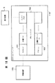
図2は図1に示した印刷装置100とホストコンピュータ200から構成される印刷システムを、ハードウェア資源により構成した場合の構成図を示している。
【0050】
ハードウェア資源として、CPU102は装置全体を制御し、また、RAM103に格納された後述する手順のプログラムを実行して図1の印刷制御装置、あるいは図18のシステムを実現する。更に、前述したアプリケーションプログラムを実行してユーザに印刷情報を入力されることもできる。RAM103はプログラムの他、記憶領域201が設けられ、設定値選択部2が格納する設定可能値やデフォルト設定値、最新の設定値等も格納する。二次記憶装置104は、RAM103にロードして使用されるプログラムや情報等を格納する。前述したRAM103に格納されるプログラムや情報は、二次記憶装置104に格納しておき、そこからRAM103にロードすることもできる。ディスプレイ105およびキーボード106、ポインティングデバイス1061は設定値をユーザが選択、あるいは入力する際に使用される。図6〜図16の画面は、ディスプレイ105により表示され、キーボードあるいはポインティングデバイスにより設定が行われる。
【0051】
このような構成のホストコンピュータ200において、印刷制御装置を実現するために、図17に示す手順のプログラムをCPU102により実行する。図17の手順は、既に図1及び図3から図16,図18を参照して説明したものであるが、改めて流れに沿って説明すると次のようなものである。
【0052】
先ず、ユーザにより印刷要求が出され、プリンタドライバが呼ばれると、設定可能値情報の要求がなされる(ステップS1)。すると設定可能値情報の取得がなされ(ステップS2)、設定可能値情報がRAM103に格納される(ステップS3)。さらにデフォルト情報の要求がなされ(ステップS4)、デフォルト情報が取得され(ステップS5)、デフォルト情報がRAM103へ格納される(ステップS6)。これらデフォルト情報は、ディスプレイ105へ表示される(ステップS7)。
【0053】
ここでユーザにより印刷の実行が指示されたか判断する(ステップS8)。ユーザにより印刷の実行が指示された場合には、設定値情報を制御コマンド発行部に発行する(ステップS17)。制御コマンド発行部は、制御コマンドを印刷装置100に発行し(ステップS18)、印刷装置100によって印刷出力が実行される。
【0054】
しかしながら、ユーザにより印刷指示されなかった場合には、設定値の変更をされたかどうか判断する(ステップS9)。設定値の変更が行われなかった場合には再びステップS8に戻る。
【0055】
一方、設定値の変更が行われた場合には、続いてリンク情報を要求し(ステップS10)、リンク情報を取得する(ステップS11)。リンク情報を取得すると、記憶領域に格納されている最新の設定値とリンク情報設定値とを比較し(ステップS12)、判定する(ステップS13)。比較の結果、両者が等しい場合にはステップ8に戻る。等しくない場合には、設定値の選択をユーザが行うべきか判断する(ステップS14)。この判断は、リンク情報の項目ごとに、ユーザに判断をゆだねる項目であるというフラグを予め設定しておき、それを参照することで為される。
【0056】
ユーザが選択すべきと判断した場合には、ユーザにより入力された選択を調べ(ステップS15)、変更であれば、比較結果の異なった部分をリンク情報設定値に置換し、RAM103に格納する(ステップS16)。
【0057】
ステップS14でユーザが選択すべきでないと判断した場合もステップS16に移る。
【0058】
ステップS16においてRAM103に変更後の設定値を格納したなら再びステップ8に戻り、ユーザにより印刷実行の指示がなされたか判定する。
【0059】
以上のように、本願発明に係る印刷制御装置は、印刷のための設定項目として設定される値ごとに、関連する他の設定項目およびその値をリンク情報として予め記憶しておく。いずれかの設定項目の値が変更された場合、変更された項目およびその値によりリンク情報を検索し、得られたリンク情報に含まれる項目及びその値を、新たな設定値あるいは設定値の候補とする。このため、オペレータが印刷時の設定を行う作業の負担が軽減される。また、印刷時の設定を、最適な値に設定することが容易である。
【0060】
また、デフォルト設定値を設定するようにしたので、一般的な印刷の場合にユーザは印刷情報に関する多くの設定を行わなくて済み、ユーザの負担を軽減することができる。
【0061】
さらに、ユーザにより設定値が変更された場合、他の設定項目の設定値も予め定めた最適な設定値に設定するので、許されない組合せをユーザが選択できないように制御することができる。
【0062】
ここで、本発明に係るプリンタドライバにより制御することができるプリンタの一例を説明する。図41はカラーレーザプリンタ102の断面図である。図41において、711は光学系であり、画像信号を光信号に変換するレーザ出力部(不図示)、多面体((例えば8面体)のポリゴンミラー712、このミラー712を回転させるモータ(不図示)及びf/θレンズ(結像レンズ)713などを有する。714は、レーザ光の光路を変更する反射ミラー、715は感光ドラムである。レーザ出力部から出射したレーザ光はポリゴンミラー712の一側面で反射され、f/θレンズ713及びミラー714を通つて図示矢印方向に回転している感光ドラム715の面を線状に走査(ラスタスキヤン)する。これによつて、原稿画像に対応した静電潜像が感光ドラム715の面上に形成されることになる。
【0063】
また、717は一次帯電器、718は全面露光ランプ、723は転写されなかつた残留トナーを回収するクリーナ部、724は転写前帯電器であり、これらの部材は感光ドラム715の周囲に配設されている。
【0064】
726はレーザ露光によつて、感光ドラム715の表面に形成された静電潜像を現像する現像器ユニツトであり、以下に示す構成よりなる。731Y,731M,731C,731Bkは感光ドラム715と接して直接現像を行なう現像スリーブ、730Y,730M,730C,730Bkは予備トナーを保持しておくトナーホツパー、732は現像剤の移送を行なうスクリユーであつて、これらのスリーブ731Y〜731Bk、トナーホツパー730Y〜730Bk及びスクリユー732により現像器ユニツトの回転軸Pの周囲に配設されている。尚、前述した各構成要素の符号のY,M,C,Bkは色を示している。つまり、“Y”はイエロー、“M”はマゼンタ、“C”はシアン、“Bk”はブラックである。イエローのトナー像を形成する時には、本図の位置でイエロートナー現像処理を行なう。また、マゼンタのトナー像を形成する時は、現像器ユニツト726を図の軸のPを中心に回転して、感光体715にマゼンタ現像器内の現像スリーブ731Mが接する様にする。シアン、ブラックの現像も同様に作動する。
【0065】
また、716は感光ドラム715上に形成されたトナー像を用紙に転写する転写ドラムであり、719は転写ドラム716の移動位置を検出させるためのアクチユエータ板、720はこのアクチユエータ板719と近接することにより転写ドラム716がホームポジシヨン位置に移動したのを検出するポジシヨンセンサ、725は転写ドラムクリーナ、727は紙押えローラ、728は徐電器、729は転写帯電器であり、これらの部材719,720,725,727,729は転写ローラ716の周囲に配設されている。
【0066】
一方、735,736は用紙(紙葉体)を収納する給紙カセツトであり、実施例では給紙カセツト735には例えばA4サイズの用紙、給紙カセツト736にはA3サイズの用紙が収納されているものとする。737,738はカセツト735,736から用紙を給紙する給紙ローラ、739,740,741は給紙及び搬送のタイミングを取るタイミングローラであり、これらを経由して給紙搬送された用紙は紙ガイド749に導かれて先端を後述のグリツパに但持されながら転写ドラム716に巻き付き、像形成過程に移行する。尚、給紙カセツト735,736のいずれを選択するかは、主制御部31の指示により決定し、選択された給紙ローラのみが回転する様になつている。
【0067】
なお、このレーザビームプリンタに代えてインクジェットプリンタを利用することもできるが、このプリンタの構造説明は、後述の第2の実施の形態の説明においてしているため、ここでは省略する。
<第2の実施の形態>
第2の実施の形態として、図19の構成の上でプリンタドライバを実行し、印刷を行う印刷システムを説明する。
【0068】
図19において、制御部H01は本実施例の制御を司る(以後CPUと称する)。キーボードH02およびポインティングデバイスH21は、オペレータが各種データを入力する際に使用する。カラー表示器H03は、RAM H05に貯えられている画像データを表示する。ROM H04は、装置全体を制御する制御手順及びその他の必要な情報を予め記憶するリードオンリメモリ(ROM)である。RAM H05はワークエリアとして利用されるランダムアクセスメモリ(RAM)である。ハードディスクH06は各種データの読み書きやプログラムが格納されている。プリンタインターフェースH07は、印刷データの送信だけでなくプリンタH08の状態を受信する双方向のプリンタインターフェイスである。データバスH09は、各種データを転送するために用いられる。なおハードディスクH06にはアプリケーションプログラムやプリンタドライバなどが格納されており、RAM H05にロードされて、CPU H01により実行される。
【0069】
本実施形態のプリンタH08はカラーインクジェットプリンタであり3種類のヘッドを取り替えることができる。1つはモノクロ印刷用ヘッド、2つ目はカラー印刷用ヘッド、3つ目はフォトグレード印刷用ヘッドである。モノクロ印刷用ヘッドとカラー印刷用ヘッドは今までのプリンタと同じ2値のヘッドであり、印刷コマンドのイメージデータの1ビットが1ドットを意味する。フォトグレード印刷用ヘッドは淡いインクを重ね打つことで階調印刷することができるヘッドであり、本実施例では四階調の印刷が可能である。そのため1ドットを表現するためには2ビット必要とする。このようにヘッドにより1ドット印刷するために必要なビット数が異なるため、プリンタに装着されているヘッドにあった印刷コマンドを送信しなければ正しく印刷できない。
【0070】
次に図19の印刷システムの詳細を説明する。このシステムは、プリンタドライバにおいて設定された印刷ヘッドと、実際にプリンタに装着されている印刷ヘッドとが一致しているか調べ、一致しない場合にエラー表示を行い、印刷の中止かヘッドの交換を行わせるものである。
【0071】
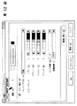
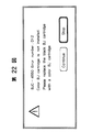
先ずプリンタドライバの画面上の動きから説明する。図20は印刷ダイアログである。印刷ダイアログとは、印刷に関する各種設定をオペレータに行なわせるための表示画面である。オペレータはこの表示を見て、適当な値を入力したり、メニューから選択することで設定を行う。設定が行われると、その設定値は、RAM H05あるいはハードディスクH06に格納される。図20において、画面中の「Cartridge」メニューがヘッド選択のメニューである。このメニューにより、前述の3種類のヘッドを設定できる。図21に「Cartridge」メニューの選択項目を示す。プリンタドライバは「Print」ボタンを押した時点における「Cartridge」メニューの設定に合わせて印刷コマンドを生成する。そしてプリンタに印刷コマンドを送信する前に、プリンタに装着されているヘッドを確認し、設定と一致していれば印刷コマンドを送信する。一致していなければ図22のエラーダイアログを表示する。この中で「Stop」ボタンを押すと印刷は中止される。「Continue」ボタンを押すと、再びヘッドの確認処理を行い、設定と実際のヘッドが一致するまで処理を繰り返す。
【0072】
次にプリンタドライバの動きをフローチャートで説明する。図23は、図20の「Print」ボタンを押してから印刷コマンドを送信するまでのフローチャートである。
【0073】
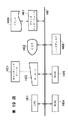
ステップS231で、図19のプリンタインターフェースH07を経由してプリンタH08に装着しているヘッドの種類を得る。ステップS231で、プリンタドライバの「Cartridge」項目の値として設定された値を得る。ステップS233で、プリンタH08に装着しているヘッドと、ステップS232で得た設定値とが一致しているか調べる。一致していればその設定をプリンタH08に送り付け、印刷処理に移行する。一致していなければステップS234に進む。ステップS234で、印刷ヘッドがドライバの設定と異なる旨を表示する。本実施形態では図22のエラーダイアログを表示する。ステップS235とS236はエラーダイアログの処理となる。ステップS235では、「Stop」ボタンが押されたか調べる。もし押されたら印刷中止へ移行する。ステップS236では、「Continue」ボタンが押されたか調べる。もし押されたらステップS231へ移行する。もし押されないならステップS235へ戻る。
【0074】
以上のようにプリンタドライバが印刷ヘッドの設定を制御することで、記録ヘッドの設定と実際の記録ヘッドとが異なることによる印刷ミスを防止することができる。
【0075】
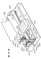
なお、図24は、本実施の形態に適用できるカラーインクジェット記録装置IJRAの概観図である。なお、このプリンタは、第1の実施の形態を初め、第2の実施の形態以外の実施形態においても用いることができる。図24において、駆動モータ5013の正逆回転に連動して駆動力伝達ギア5011,5009を介して回転するリードスクリュー5005の螺旋溝5004に対して係合するキャリッジHCはピン(不図示)を有し、矢印a,b方向に往復移動される。このキャリッジHCには、カラーヘッドを選択する場合には図24のようにY(黄),M(マゼンタ),C(シアン),Bk(黒)各色のインクジェットカートリッジIJCが搭載されている。モノクロヘッドを選択する場合には、黒のみのカートリッジを搭載し、フォトカラーを選択する場合には、フォトカラー用のカートリッジを搭載する。5002は紙押え板であり、キャリッジの移動方向に亙って紙をプラテン5000に対して押圧する。5007,5008はフォトカプラで、キャリッジのレバー5006のこの域での存在を確認して、モータ5013の回転方向切り換え等を行うためのホームポジション検知手段である。5016は記録ヘッドの前面をキャップするキャップ部材5022を支持する部材で、5015はこのキャップ内を吸引する吸引手段で、キャップ内開口5023を介して記録ヘッドの吸引回復を行う。5017はクリーニングブレードで、5019はこのブレードを前後方向に移動可能にする部材であり、本体支持板5018にこれらが支持されている。ブレードは、この形態でなく周知のクリーニングブレードが本例に適用できることは言うまでもない。又、5021は、吸引回復の吸引を開始するためのレバーで、キャリッジと係合するカム5020の移動に伴って移動し、駆動モータからの駆動力がクラッチ切り換え等の公知の伝達手段で移動制御される。
<第3の実施の形態>
次に本発明のもう一つの実施形態を示す。本実施形態においては、プリンタドライバの用紙サイズの選択と実際にプリンタに入っている用紙サイズとが一致しているか調べて、一致しない場合にエラー表示を行い、印刷の中止か用紙の交換を行うものである。プリンタの構成は、第2の実施の形態と同じく、図19のように構成される。
【0076】
まずプリンタドライバの画面上の動きから説明する。図25は用紙設定ダイアログである。用紙設定ダイアログは、印刷用紙の大きさ、倍率、縦横の設定を行うための画面である。設定される値は、RAM H08やハードディスクH06に格納される。オペレータはこの画面上の各項目に所望の値を設定、あるいはメニューから選択することで、印刷用紙サイズ等を設定する。図25において、「Paper Size」メニューが用紙サイズのメニューである。本実施形態のプリンタは、13種類の用紙サイズをサポートしているプリンタである。図26に「Paper Size」メニューの選択項目を示す。図25のダイアログの「OK」ボタンは用紙サイズの決定を意味しており、印刷実行の指示ではない。印刷は図20の印刷ダイアログで、「プリント」ボタンを選択して行う。プリンタドライバは印刷ダイアログの「Print」ボタンが押されたとき、「Paper Size」項目として設定された値に合わせて印刷コマンドを生成する。そしてプリンタに印刷コマンドを送信する前に、プリンタに入っている用紙サイズを確認し、設定値と一致していれば印刷コマンドをプリンタに送信する。一致していなければ図27のエラーダイアログを表示する。この中で「Stop」ボタンを押すと印刷は中止される。「Continue」ボタンを選ぶと再び用紙サイズの確認処理を行い、用紙サイズが一致するまで処理を繰り返す。
【0077】
次にプリンタドライバの動きをフローチャートで説明する。図28は、図20の「Print」ボタンを押してから印刷コマンドを送信するまでのフローチャートである。
【0078】
ステップS281では、図19のプリンタインターフェースH07を経由してプリンタH08にセットされている用紙サイズを得る。ステップS282では、図25のダイアログによりオペレータに設定された「Paper Size」項目の値を得る。ステップS283で、プリンタに入っている用紙サイズとプリンタドライバに対して図25のダイアログにおいて設定された値とが一致しているか調べる。一致していれば印刷処理に移行する。一致していなければステップS284に進む。ステップS284では用紙サイズが異なる旨を表示する。本実施の形態では図27のエラーダイアログを表示する。ステップS285とステップS286はエラーダイアログの処理となる。ステップS285では「Stop」ボタンが押されたか調べる。もし押されたら印刷中止へ移行する。ステップS286は「Continue」ボタンが押されたか調べる。もし押されたらステップS281のステップへ移行する。もし押されないならステップS285へ戻る。
【0079】
以上の手順により、プリンタにセットされた用紙サイズと、プリンタドライバに対して設定された用意サイズとが一致しているか確認することができるため、用紙サイズの誤りによる印刷ミスを防止することができる。
<第4の実施の形態>
次に、プリンタドライバの設定とプリンタの設定が異なる場合、エラー表示ではなく別のプリンタを選び直す印刷システムを説明する。例として第1の実施の形態の印刷システムと同じ構成のシステムを説明する。
【0080】
まずホストとプリンタの接続を図31に示す。図のPC311がホストでプリンタ312〜314が接続されている。プリンタ312〜314はそれぞれ名前がついている。次にプリンタドライバの画面上の動きを説明する。図29は印刷ダイアログである。この中の「Cartridge」メニューがヘッド選択のメニューである。プリンタドライバは「Print」ボタンを押したときの「Cartridge」メニューの設定に合わせて印刷コマンドを生成する。そしてプリンタに印刷コマンドを送信する前にプリンタに装着されているヘッドを確認し一致していれば送信する。一致していなければ図30のエラーダイアログを表示する。図30には、PC311接続されているプリンタが表示される。この中で「Stop」を押すと印刷は中止される。プリンタを表示から選択し、「Choose」ボタンを押すと、選択されたプリンタに対して再びヘッドの確認処理を行い、ヘッドが一致するまで処理を繰り返す。
【0081】
次にプリンタドライバの動きをフローチャートで説明する。図32は本実施例の「Print」ボタンを押してから印刷コマンドを送信するまでのフローチャートである。
【0082】
ステップS321では、図91のプリンタインターフェースH07を経由してプリンタH08に装着されているヘッドの種類を得る。ステップS322では、プリンタドライバに対して「Cartridge」項目として設定された値を得る。ステップS323では、プリンタH08に装着されているヘッドとプリンタドライバの設定とが一致しているか調べる。一致していれば印刷処理に移行する。一致していなければステップS324に進む。ステップS324ではヘッドが異なる旨を表示する。本実施形態では図30のエラーダイアログを表示する。ステップS325とステップS326はエラーダイアログの処理となる。ステップS325では「Stop」ボタンが押されたか調べる。もし押されたら印刷中止へ移行する。ステップS326では「Choose」ボタンが押されたか調べる。もし押されたら、ステップS327で、その時点で選択されている新しいプリンタを、印刷を制御すべきプリンタとして選択し、そのプリンタに対してステップS321のステップから実行し直す。もし押されないならS25へ戻る。
<第5の実施の形態>
次にプリンタドライバの設定とプリンタの設定が異なる場合、エラー表示ではなくプリンタの設定に合わせて、プリンタドライバの設定を変更する印刷システムを説明する。例として第1の実施の形態と同様に印刷ヘッドが異なる場合を説明する。
【0083】
まずプリンタドライバの画面上の動きから説明する。図33は印刷ダイアログである。印刷ダイアログとは印刷に関する各種設定を行い印刷を実行するダイアログである。この中の「Cartridge」メニューがヘッド選択のメニューである。本印刷システムでは、プリンタには3種類のヘッドが存在する。1つはモノクロ印刷用ヘッド、2つ目はカラー印刷用ヘッド、3つ目はフォトグレード印刷用ヘッドである。プリンタドライバは「Print」ボタンを押したときの「Cartridge」メニューの設定に合わせて印刷コマンドを生成する。そしてプリンタに印刷コマンドを送信する前にプリンタに装着しているヘッドを確認し一致していれば送信する。一致していなければ図34のエラーダイアログを表示する。この中で「Stop」を押すと印刷は中止される。「OK」を選ぶとプリンタに装着されているヘッドに合わせて印刷コマンドを生成する。
【0084】
次にプリンタドライバの動きをフローチャートで説明する。図35は本実施形態における図33の「Print」ボタンを押されて、印刷実行の指示が出されてから印刷コマンドを送信するまでのフローチャートである。
【0085】
ステップS351では図19のプリンタインターフェースH07を経由して、プリンタH08に装着されているヘッドの種類を得る。ステップS352では、プリンタドライバに対して「Cartridge」項目の値として設定された値を得る。ステップS353ではプリンタH08に装着されているヘッドとプリンタドライバに対する設定とが一致しているか調べる。一致していれば印刷処理に移行する。一致していなければステップS354に進む。ステップS354は、設定されたヘッドと実際に取り付けられたヘッドとが異なる旨を表示する。本実施の形態では、図34のエラーダイアログを表示する。ステップS355とステップS356はエラーダイアログの処理となる。ステップS355では「Stop」ボタンが押されたか調べる。もし押されたらステップS357へ移行する。もし押されないならステップS355へ戻る。ステップS357ではプリンタドライバの設定をプリンタに装着しているヘッドに合わせる。以後の印刷のステップは、プリンタドライバの設定に合わせてコマンドを生成するため、装着ヘッドに合ったコマンドが生成される。
【0086】
なお、本実施の形態ではカートリッジの種類を対象としているが、用紙のサイズなどでも同様に処理できる。
【0087】
以上のように、プリンタ本体に対する設定に、プリンタドライバに対する設定を合わせることで、印刷時の設定誤りによる印刷ミスを防止することができる。
【0088】
なお、以上の第2〜第5実施形態以外にも、例えば用紙タイプや給紙口の設定とプリンタドライバの設定が異なる場合でも、同じような処理を行うことで正しく印刷できるようになる。また、プリンタからホストへ設定情報を伝えることができるなら物理的なIFとして何を使っても良い。
<第6の実施の形態>
本発明を実現するためのハードウェア構成は、第2〜第5の実施の形態と同じく図19に示した通りである。
【0089】
本実施の形態におけるプリンタドライバの一般的な印刷処理の開始部分を説明する。プリンタドライバは印刷前に印刷処理の設定を行うダイアログを表示し、ユーザは印刷物に合わせた印刷処理の設定を行い、印刷の実行を指示する。ここでユーザに設定された印刷処理の設定を印刷設定と呼ぶ。印刷設定には以下に説明するヘッド情報以外にも、用紙サイズ、用紙タイプ、印刷方法、給紙口の指定などがある。
【0090】
次に本印刷システムの詳細を説明する。本実施の形態におけるシステムは、プリンタドライバの印刷ダイアログの表示をしながらプリンタに装着されているヘッドを調べ、装着中のヘッドの合わせたカートリッジメニューを表示する。
【0091】
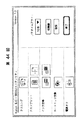
先ずプリンタドライバの画面上の動きから説明する。図36は印刷ダイアログである。この中の「Cartridge」メニューがヘッド選択のメニューである。本実施形態では、プリンタに3種類のヘッドが存在する。1つはモノクロ印刷用ヘッド、2つ目はカラー印刷用ヘッド、3つ目はフォトグレード印刷用ヘッドである。図37から図39が「Cartridge」メニューである。図37はカラーヘッドが、図38はモノクロヘッドが、図39はフォトグレード印刷用ヘッドが装着されているときに表示されるメニューである。プリンタドライバは装着されているヘッドに合わせて自動的にメニューを変更する。
【0092】
次にプリンタドライバの動きをフローチャートで説明する。図40は本実施形態のシステムにおける印刷ダイアログの処理のフローチャートである。印刷がオペレータにより指示されると、図40の手順で処理が開始される。
【0093】
ステップS401では印刷設定の初期設定を行う。ステップS402では現在の印刷設定に合わせてダイアログの表示を行う。ステップS403では、図19のプリンタインターフェースH07を通じてプリンタH08に装着されているヘッドを調べる。ステップS404では印刷設定のヘッドの設定とプリンタに装着されているヘッドとを比較する。もし一致していればステップS408に進む。一致していなければプリンタに装着されているヘッドに合わせて処理を分岐する。もしモノクロヘッドが装着されていればステップS405へ、カラーヘッドが装着されていればステップS406へ、フォトグレード印刷用ヘッドが装着されていればステップS407へ進む。ステップS405では印刷設定のヘッド情報をモノクロに設定する。ステップS406では印刷設定のヘッド情報をカラーに設定する。ステップS407では印刷設定のヘッド情報をフォトグレード印刷様に設定する。ステップS408では印刷ダイアログの印刷ボタンが押されたか調べる。押されていれば印刷処理に移行する。押されていなければステップS409へ進む。ステップS409では印刷ダイアログ全般の処理を行う。ここでは、印刷方法や給紙口などの印刷設定を変更する。ステップS410ではステップS409のステップで印刷設定が変更されたか調べる。印刷設定が変更されているならステップS402へ進み、変更されていないならステップS403へ進む。以上のように、プリンタに実際に装着されているカートリッジと、プリンタドライバに対する設定とが異なる場合、ドライバの設定をプリンタの状態に合わせることで、設定操作が容易になるとともに、設定の誤りによる印刷ミスを防止できる。
【0094】
第6の実施形態以外にも、用紙サイズや用紙の給紙状態なども、図40と同様の手順で設定処理を行うことで、常に正しい設定で印刷処理が行えるようになる。また、プリンタからホストへ設定情報を伝えることができるなら物理的なIFとして何を使っても良い。
<第7の実施の形態>
本発明を実現するためのプリンタシステムのハードウェア構成を図42を用いて説明する。図19と共通の構成には同じ番号を付してその説明を省略する。図19と異なるのは、プリンタH08に、3種類のカートリッジごとのインク残量を計測するためのカウンタH801,H802,H803が備えられていることである。カートリッジを交換すると自動的にインク残量カウンタが切り替わる。ただし、使用量を自動的にリセットすることはない。また、図18のようなソフトウエア構成を有し、プリンタドライバがCPU H01により実行されることでプリンタH08が制御される。さらに、プリンタH08は、装着されたカートリッジの種類を判別することができる。これは、カートリッジに、その種類に応じた突起などの識別子を予め付けておき、それをプリンタ本体のセンサで検知することで実現できる。
【0095】
次に本実施例を画面上の表示とあわせて説明する。図44は、プリンタH08に対するクリーニングやカートリッジ交換等を指示するためのユーティリティダイアログ画面である。この画面は、プリンタドライバのユーティリティを使用する旨、オペレータがキーボードやポインティングデバイス等で入力を行うことで表示器H03に表示される。この画面において、カートリッジ交換ボタンを押す、すなわちポインティングデバイスによりそのボタンを選択し、実行指示すると、プリンタドライバはカートリッジ交換処理を開始する。先ずカートリッジをカートリッジ交換ポジションに移動し、カートリッジ交換が行われるのを待つ。新しいカートリッジが装着されるまで図45のダイアログが表示される。カートリッジの交換が済むと(カートリッジのセンサで判定できる)、もし別のタイプのカートリッジが装着された場合は処理を終了する。もし同じタイプのカートリッジが装着された場合、図46のダイアログを表示し、インク残量のリセットを行うかオペレータに選択を要求する。もしインク残量のリセットが選ばれたらインク残量カウンタのリセットを行い、選ばれなかったら何もせず終了する。
【0096】
次にこれをフローチャートで説明する。図43は、プリンタドライバにおけるカートリッジ交換に係る部分のフローチャートである。このフローチャートは図44のカートリッジ交換ボタンを押した後の処理を示したものである。
【0097】
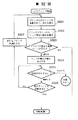
ステップS431では交換前、すなわち現在装着されているカートリッジタイプを取得する。すなわち、プリンタH08のカートリッジを識別するセンサにより」検知されているカートリッジの種類を要求する。ここで図45のダイアログが表示される。ステップS432ではカートリッジをカートリッジ交換ポジションに移動させるためのコマンドを送信する。この結果、プリンタのカートリッジは交換位置まで移動する。
【0098】
ステップS433では、カートリッジ交換が終了したかどうかのステータスを取得するステップである。プリンタH08では、例えば、カートリッジのセンサから一旦カートリッジが外れ、再び検知したなら交換が終了したものと判定すれば良い。プリンタでは、これをカートリッジ交換終了のステータスとして、プリンタドライバに応答する。ステップS434では、取得したステータスを基にカートリッジ交換が終わったかどうか判断する。交換が終了していなければステップS433へ戻る。ステップS435では新しく装着されたカートリッジタイプを取得する。ここではステップS431と同じ処理を行なえば良い。
【0099】
ステップS436では、カートリッジ交換前後のカートリッジタイプが同じかどうか、ステップS431で取得したカートリッジタイプと、ステップS435で取得したタイプとを比較して判断する。異なるカートリッジタイプであればカートリッジ交換処理を終了する。ステップS437では図46を表示し、インク残量をリセットするかどうか選択させるステップである。インク残量をリセットしないならカートリッジ交換処理を終了する。
【0100】
ステップS438では交換されたカートリッジがモノクロカートリッジかカラーカートリッジか判断するステップである。モノクロカートリッジならステップS439へ移行し、カラーカートリッジならステップS440へ移行する。ステップS439ではモノクロカートリッジのインク残量のリセットコマンドを、プリンタH08に送信する。ステップS438では、カラーカートリッジのインク残量のリセットコマンドをプリンタH08に送信する。なお、図43ではカートリッジの種類は2種類しか扱っていないが、3種類であっても、それ以上であっても、それぞれに対応する残量カウンタのリセットを行なえばよい。
【0101】
以上のようにして、装着されたカートリッジに応じたインク残量カウンタをリセットすることができるため、カートリッジの交換時にリセットすべき残量カウンタを誤り、プリンタがインク残量を誤検出することを防止できる。
[他の実施例]
先の実施例ではプリンタドライバからインク残量のリセットを行っていたが、プリンタ本体のファームウェアで行っても同じ効果があることは言うまでもない。
【0102】
【発明の効果】
以上説明したように本発明は、
カートリッジ交換前のカートリッジタイプを取得するカートリッジタイプ取得ステップ1と、カートリッジ交換を行うカートリッジ交換ステップと、カートリッジ交換後のカートリッジタイプを取得するカートリッジタイプ取得ステップ2と、カートリッジ交換前後のカートリッジタイプを比較するカートリッジタイプ比較ステップと、もし同じカートリッジタイプならインク残量をリセットするインク残量リセットステップを有することで、交換したカートリッジタイプを自動的に認識しインク残量を正しくリセットするものである。
【その他の実施形態】
なお、本発明は、複数の機器(例えばホストコンピュータ、インタフェイス機器、プリンタなど)から構成されるシステムに適用しても、一つの機器からなる装置(例えば、複写機、ファクシミリ装置など)に適用してもよい。また、本発明はシステムあるいは装置にプログラムを供給することによって達成される場合にも適用できる。この場合、本発明を達成するためのソフトによって表されるプログラムを格納した記憶媒体を該システムあるいは装置に読み出すことによって、そのシステムあるいは装置が、本発明の効果を享受することが可能となる。
【0103】
プログラムコードを供給するための記憶媒体としては、例えば、フロッピディスク、ハードディスク、光磁気ディスク、CD−ROM、磁気テープ、不揮発性のメモリカード、ROM等を用いることができる。
【0104】
また、コンピュータが読み出したプログラムコードを実行することにより、前述した実施形態の機能が実現されるだけでなく、そのプログラムコードの指示に基づき、コンピュータ上で稼働しているOS(オペレーティングシステム)などが実際の処理の一部または全部を行い、その処理によって前述した実施形態の機能が実現される場合も含まれる。
【0105】
さらに、記憶媒体から読み出されたプログラムコードが、コンピュータに挿入された機能拡張ボードやコンピュータに接続された機能拡張ユニットに備わるメモリに書き込まれた後、そのプログラムコードの指示に基づき、その機能拡張ボードや機能拡張ユニットに備わるCPUなどが実際の処理の一部または全部を行い、その処理によって前述した実施形態の機能が実現される場合も含まれる。
【0106】
本発明を上記記憶媒体に適用する場合、その記憶媒体には、先に説明したフローチャートに対応するプログラムコードを格納することになるが、簡単に説明すると、図42のメモリマップ例に示す各モジュールを記憶媒体に格納することになる。
【0107】
すなわち、少なくとも、制御情報の各項目の値を入力する入力工程のコードと、前記入力工程により制御情報が入力された場合、入力された項目の値に応じて、前記制御情報の所定の項目について、該項目の値に応じて変更すべき項目とその値とを予めリンク情報として格納しているリンク情報格納手段より、リンク情報を読み出す読出し工程のコードと、前記読出し工程により読出したリンク情報に基づいて、該リンク情報に含まれる項目および値に基づいて、該当する項目の値を設定する設定工程のコードと、前記入力工程または前記設定工程により設定された制御情報の最新の値を格納する最新値格納工程のコードの各モジュールのプログラムコードを記憶媒体に格納すればよい。
【0108】
あるいは、図43のメモリマップ例に示す各モジュールを記憶媒体に格納することになる。
【0109】
すなわち、少なくとも、制御情報の項目の値を入力する設定工程のコードと、前記印刷装置から、その設定状態を取得する設定取得工程のコードと、前記設定工程により設定された項目と、前記設定取得工程により取得された設定状態とを比較する比較工程のコードと、前記比較工程による比較の結果、設定された項目の値と、取得された設定状態とが異なる場合、その旨を表示する表示工程のコードの各モジュールのプログラムコードを記憶媒体に格納すればよい。
【0110】
あるいは、図44のメモリマップ例に示す各モジュールを記憶媒体に格納することになる。
【0111】
すなわち、少なくとも、制御情報の項目の値を設定する設定工程のコードと、前記印刷装置から、その設定状態を取得する設定取得工程のコードと、前記設定工程により設定された項目と、前記設定取得工程により取得された設定状態とを比較する比較工程のコードと、前記比較工程による比較の結果、設定された項目の値と、取得された設定状態とが異なる場合、異なる項目については、前記設定取得工程により取得した状態を設定する再設定工程のコードの各モジュールのプログラムコードを記憶媒体に格納すればよい。
【0112】
あるいは、少なくとも、前記制御情報の項目の値を設定する設定工程のコードと、前記印刷装置から、その設定状態を取得する設定取得工程のコードと、前記設定工程により設定された項目と、前記設定取得工程により取得された設定状態とを比較する比較工程のコードと、前記比較工程による比較の結果、設定された項目の値と、取得された設定状態とが異なる場合、異なる印刷装置に制御対象を移す再設定工程のコードの各モジュールのプログラムコードを記憶媒体に格納すればよい。
【0113】
【発明の効果】
以上説明したように、本発明によれば、ユーザは最小限の設定を行うだけで、最適な印刷を実行することができる。ユーザにより選択される情報の内容や数が変わった場合や、印刷装置に提供する情報の内容や数が変わった場合でも、情報の組合せを予め代えておくだけで対応することができる。
【0114】
また、デフォルト設定値を設定するようにしたので、一般的な印刷の場合にユーザは印刷情報に関する多くの設定を行わなくて済み、ユーザの負担を軽減することができる。
【0115】
さらに、ユーザにより任意の設定値が変更された場合、他の設定項目の設定値も予め定めた最適な設定値に設定するようにしたので、本来ならば許されない組合せをユーザが選択できないように制御することができ、設定値変更に伴う被害を最小限に食い止めることが可能となる。
【0116】
また、プリンタドライバとプリンタの設定を一致させ正しい印刷ができるようになる。
【0117】
【図面の簡単な説明】
【図1】本発明の実施の形態の印刷制御装置のブロック図である。
【図2】ホストコンピュータと印刷装置とから構成される印刷システムのブロック図である。
【図3】従来例のメニューの表示例を示す図である。
【図4】設定可能値格納部に格納された設定項目と設定値を示す図である。
【図5】デフォルト設定値格納部に格納されたデフォルト設定値を示す図である。
【図6】デフォルト設定値でのメインプロパティの具体例を示す図である。
【図7】デフォルト設定値での用紙プロパティの具体例を示す図である。
【図8】デフォルト設定値でのクオリティプロパティの具体例を示す図である。
【図9】デフォルト設定値での色設定プロパティの具体例を示す図である。
【図10】オートパレットの設定値をワープロから写真フィルムへ変更した場合のメインプロパティの状態を示す図である。
【図11】オートパレットの設定値をワープロから写真フィルムへ変更した場合のクオリティプロパティの状態を示す図である。
【図12】オートパレットの設定値をワープロから写真フィルムへ変更した場合の色設定プロパティの状態を示す図である。
【図13】メディアの設定値を光沢フィルムからコート紙へ変更する際のクオリティプロパティの状態を示す図である。
【図14】ユーザの判断を仰ぐ場合の表示例を示す図である。
【図15】給紙方法の設定値がオートシートフィーダに、メディアタイプの設定値がコート紙にそれぞれ変更された場合を示す図である。
【図16】メディアタイプの設定値がコート紙に変更された場合を示す図である。
【図17】本実施形態のプリンタドライバのフローチャートである。
【図18】第1の実施形態のシステムのソフトウエア構成を示す図である。
【図19】第2〜第6の実施形態の印刷システムのハードウェア構成図である。
【図20】印刷ダイアログを示す図である。
【図21】カートリッジメニューを示す図である。
【図22】ヘッドミスマッチのエラーダイアログを示す図である。
【図23】第2の実施の形態におけるヘッドチェックのフローチャートである。
【図24】第1〜第6の実施の形態により使用できるインクジェットプリンタの構成を示す図である。
【図25】用紙設定ダイアログを示す図である。
【図26】用紙サイズメニューを示す図である。
【図27】用紙ミスマッチエラーのダイアログを示す図である。
【図28】第3の実施の形態における用紙サイズチェックのフローチャートを示す図である。
【図29】印刷ダイアログ2を示す図である。
【図30】プリンタ選択ダイアログを示す図である。
【図31】プリンタが複数繋がっている様子を示す図である。
【図32】第4の実施の形態におけるヘッドチェックのフローチャートである。
【図33】印刷ダイアログ3を示す図である。
【図34】モノクロ印刷の確認ダイアログを示す図である。
【図35】第5の実施の形態におけるヘッドチェックのフローチャートである。
【図36】第6の実施形態における印刷ダイアログを示す図である。
【図37】カラーヘッドが装着されているときのカートリッジメニューを示す図である。
【図38】モノクロヘッドが装着されているときのカートリッジメニューを示す図である。
【図39】フォトグレード印刷用ヘッドが装着されているときのカートリッジメニューを示す図である。
【図40】第6の実施の形態における印刷ダイアログ表示のフローチャートである。
【図41】カラーレーザビームプリンタの断面図である。
【図42】第7の実施の形態における印刷システムのハードウエア構成を示すブロック図である。
【図43】第7の実施の形態における印刷システムのプリンタドライバによるインクカートリッジ交換時の処理のフローチャートである。
【図44】プリンタドライバのユーティリティダイアログの例を示す図である。
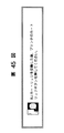
【図45】カートリッジ交換中であることを示すダイアログの例の図である。
【図46】インク残量カウンタのリセッとを促すダイアログの例の図である。
【図47】本発明に係る印刷制御プログラムを格納するメモリのメモリマップである。
【図48】本発明に係る印刷制御プログラムを格納するメモリのメモリマップである。
【図49】本発明に係る印刷制御プログラムを格納するメモリのメモリマップである。[0001]
BACKGROUND OF THE INVENTION
The present invention relates to a printing control apparatus and method capable of setting detailed setting values of functions of a printing apparatus.
[0002]
[Prior art]
Conventionally, there has been known a print control apparatus that provides information necessary for printing to a printing apparatus capable of selecting a plurality of types of printing paper and various printing methods. As a print control device, a user selects or inputs various information necessary for printing, and obtains information necessary for printing by combining the selected or input information, and provides the information to the printing device It has been known.
[0003]
The print control device can print information necessary for printing, for example, “paper size”, “print color”, “media type”, “print quality”, “paper feeding method”, “dithering method”, “color”. Since the setting value is displayed for each setting item such as “processing information” as shown in FIG. 3, the user selects or inputs the setting value from these displayed items.
[0004]
For example, in many color ink jet printers, the head for monochrome printing and the head for color printing are separate, and the head must be exchanged according to the printing purpose. Therefore, the conventional print control apparatus can set color printing and monochrome printing.
[0005]
In addition, in order to check the remaining ink amount for a printer without an ink remaining amount sensor, the amount of ink used in the printer is often counted and the remaining amount is detected based on how much ink is used. In such a printer, when the cartridge is replaced, the operator has to reset the remaining amount of ink in accordance with the replaced cartridge.
[0006]
[Problems to be solved by the invention]
However, in the above conventional example, the user needs to select or input various pieces of information necessary for printing, and thus the burden on the user is large. In addition, there is a high possibility that optimum printing cannot be performed due to incorrect input or selection of information. For example, although “A-paper” is selected as the setting value of the setting item “media type” in order to print on paper (referred to as A-paper) for which manual feeding must be selected as the paper feeding method, the setting item When “Auto Sheet Feeder” is selected as the setting value of “Paper Feed Method”, manual feed is not performed, and printing defects such as paper jams may occur.
[0007]
In addition, information is combined in the print control device, and information necessary for printing is created from the result and provided to the printing device. If the content or number of input information changes, it is provided to the printing device. When the content or number of information to be changed changes, it is difficult for the user to respond to these changes.
[0008]
Further, when the operator instructs the resetting of the remaining ink amount in accordance with the replacement of the cartridge, there is a case where the remaining ink amount is incorrect if the cartridge to be reset is different from the actually replaced cartridge.
[0009]
SUMMARY OF THE INVENTION A first object of the present invention is to provide a print control apparatus and method that can solve the above-described problems and can reduce the burden of inputting user setting values.
[0010]
Even if a color / monochrome head is attached to the printer, the print data is sent to the printing device according to the setting of the print control device by the operator. I couldn't print.
[0011]
The second object of the present invention is to confirm the status of the printer before printing, display if the setting of the print control device is different from the status of the printer, and indicate that the printer setting is the same as the setting of the print control device. It is an object of the present invention to provide a print control apparatus capable of performing correct printing by changing to the above.
[0012]
The third object of the present invention is to compare the cartridge mounted before the cartridge replacement with the cartridge mounted after the replacement, and reset the ink remaining amount in accordance with the replaced cartridge. It is an object of the present invention to provide a printing control apparatus and method that can correctly handle a printer.
[0013]
[Means for Solving the Problems]
The present invention Information processing equipment Has the following structure.
[0015]
Display means for displaying a setting screen for setting a setting value of a first setting item for printing and a setting value of a second setting item for printing;
When the setting value of the first setting item for printing displayed on the setting screen is changed from the first value to the second value, the second setting for printing displayed on the setting screen First determination means for determining whether or not the user should determine when it is determined that the third value of the item should be changed;
If it is determined by the first determination means that the user should determine, a screen for allowing the user to determine whether or not to change is displayed, and a second determination for determining whether or not the user's determination is a change. Means,
When it is determined by the second determination means that the user's determination is a change and when the first determination means determines that the user should not be determined, Based on the information including the setting value of the item to be changed as the setting value of the first setting item is changed from the first value to the second value And changing means for changing the third value of the second setting item for printing displayed on the setting screen to the fourth value.
[0019]
DETAILED DESCRIPTION OF THE INVENTION
Hereinafter, a printing system according to an embodiment of the present invention will be described with reference to the accompanying drawings.
<First Embodiment>
FIG. 1 is a drawing that best represents the characteristics of a printing system to which the present invention is applied. The printing system will be described with reference to FIG.
[0020]
In FIG. 1, a
[0021]
In the
[0022]
The default
[0023]
The link
[0024]
The print
[0025]
The link information includes setting items / setting values that can be set by the setting
<Operation of print control device>
Next, the operation of the apparatus shown in FIG. 1 will be described. When printing is requested by the user to the
[0026]
The setting
[0027]
In this state, when the user instructs execution of printing, the setting
[0028]
However, the user does not always execute printing with the default setting value, and may change the setting value. When the user changes the setting value of a setting item by operating the
[0029]
Each time the user changes the setting value, the information is exchanged. The user instructs the execution of printing, and the setting information of each setting value is issued to the control
<Setting the printer driver in the computer system>
The present invention will be described with reference to more specific examples. In the following example, a printer driver in a computer system having a program configuration as shown in FIG. This printer driver corresponds to the
[0030]
In the system shown in FIG. 18, when a user creates data using application software (for example, word processor software) 183 and intends to execute printing with a printer, the user instructs printing execution through an input device such as a keyboard or a mouse. give. This instruction is transmitted from the
[0031]
That is, in the
[0032]
FIG. 6 to FIG. 9 show various settings for the printer driver according to the present invention when a user using the operating system “Windows 95” manufactured by Microsoft Corporation instructs printing from the application software. It is a screen to show.
[0033]
FIG. 6 shows a screen called a main property. On this screen, the user can set an “auto palette” column for selecting a printing method suitable for the application software used by the user with one touch. In addition, a message indicating the position to move the “Paper Selection Lever” field or “Paper Selection Lever” field and the settings of the “Media Type” and “Paper Source” fields is displayed. Has been. The default setting value for each setting item is “Auto Palette” = “Word Processor”, “Paper Selection Lever” = “Back”, “Paper Selection Lever” = “Center”, “Media” = “Normal” “Paper”, “paper feeding method” = “auto sheet feeder”, and these are displayed on the display device.
[0034]
FIG. 7 shows a screen called a paper property. In this screen, the “paper size” field indicating the size of the paper specified in the application is different from the size specified in the “paper size” field and the paper size actually loaded in the printer. In this case, the “enlargement / reduction” check box indicating that the image is enlarged / reduced, the “printing direction” field for specifying the printing direction, the “color mode” field for specifying the printing color, etc. Can be set. The default setting values of each setting item are “paper size” = “A4”, “enlarge / reduce” = “OFF”, “printing direction” = “vertical”, “color mode” = “color”. Is displayed on the display device.
[0035]
FIG. 8 shows a screen called a quality property that opens when the “detail setting” button in FIG. 6 is pressed. In this screen, a “print quality” slide bar for specifying the print quality, a “resolution” / “print mode” message indicating the resolution and the print mode status in the designated “print quality” slide bar, The user can designate a “paper feeding method” field for designating a paper feeding method, a “media” field for designating media, a “dithering setting” field for designating dithering processing, and the like. The default setting values of the setting items are “print quality” = “second from the left”, “resolution” / “print mode” messages “360 × 360 dpi”, “HQ”, “paper feeding method” = “ “Auto sheet feeder”, “Media” = “plain paper”, “Dithering setting” = “Pattern (high speed)”, and these are displayed on the display device.
[0036]
FIG. 9 is a screen called a color setting property that can be opened after the screen of FIG. 8 is opened. On this screen, the user can set a “density” column for changing the density of data at the time of printing, a “color correction” column for performing various color corrections, and the like. The default setting values of the respective setting items are “density” = “0” and “color correction” = “OFF”, and these are displayed on the display device.
[0037]
Normally, the user selects an application type from the “auto palette” of the main property in the
[0038]
When the user presses the “OK” button in FIG. 6 to execute printing with the default setting values, the default setting values stored in the
[0039]
However, the user does not always execute printing with the default setting value, and may change the setting value. An example of this will be described below.
[0040]
FIG. 10 is a screen showing a state in which “photographic film” is selected as the main property “auto palette” when an image created by the photo retouching program is printed on glossy film paper.
[0041]
In FIG. 10, “paper gap selection lever” = “forward”, “paper selection lever” = “middle”, “media” = “glossy film”, and “paper feeding method” = “manual feed”. In other words, a message is sent to the user: "Move the paper gap selection lever to the front, move the paper selection lever to the center, change the media to be set in the printer to glossy film, and feed it manually." It supports the operations necessary to perform the printing desired by the user. If the user operates as instructed by the printer driver and executes printing, a printing result suitable for the photographic film can be obtained.
[0042]
The user who is not satisfied with the main property “auto palette” = photographic film setting and wants more detailed settings presses the “detail setting” button of the main property. Then, the quality property of FIG. 11 is opened. On this screen, the user can change the media and dithering processing, or open the color setting properties shown in FIG. 12 and perform detailed settings such as density adjustment and color balance.
[0043]
In FIG. 11, “Dithering setting” = “Pattern (high speed)” is grayed out and cannot be selected by the user, and “error diffusion” is selected. Grayout means that buttons that cannot be selected are displayed in gray, but the grayout is not particularly shown in the figure. The display as shown in FIG. 11 is performed because the following operation is performed when the user selects “photographic film” instead of “word processor” as the main property “auto palette” in the
[0044]
A link information request command 29 relating to auto pallet = “photographic film” is issued from the set
[0045]
In this way, the link information includes setting items / setting values that can be set by the setting value selection unit 2 (in this example, “error diffusion”) and non-setting items / setting values that cannot be set (in this example, “pattern ( High speed))). The link
[0046]
Further, the message item of “resolution” is changed from “360 × 360 dpi” to “720 × 360 dpi”, and the message item of “print mode” is changed from “HQ” to “FINE”. All of these changes were linked to changes in the settings of the main property "Auto Palette". In FIG. 11, “Dithering setting” = “Pattern (high speed)” is grayed out, so that high-speed printing with inferior print quality can be prevented from being performed on a glossy film that is a high-quality medium.
[0047]
When the user uses coated paper instead of glossy film to execute printing with the “Auto Palette” field set to “Photo Film”, the setting value of the setting item “Media” is set to “ Change from "Glossy Film" to "Coated Paper". Then, the setting
[0048]
Such exchange of information is performed between the set
[0049]
When the OK button on the main property is pressed, the latest setting value information stored in the
<Hardware configuration>
FIG. 2 is a configuration diagram when the printing system configured by the
[0050]
As a hardware resource, the
[0051]
In the
[0052]
First, when a print request is issued by the user and the printer driver is called, a request for settable value information is made (step S1). Then, the settable value information is acquired (step S2), and the settable value information is stored in the RAM 103 (step S3). Further, a request for default information is made (step S4), the default information is acquired (step S5), and the default information is stored in the RAM 103 (step S6). The default information is displayed on the display 105 (step S7).
[0053]
Here, it is determined whether execution of printing is instructed by the user (step S8). When the execution of printing is instructed by the user, the setting value information is issued to the control command issuing unit (step S17). The control command issuing unit issues a control command to the printing apparatus 100 (step S18), and printing output is executed by the
[0054]
However, if the user has not instructed printing, it is determined whether or not the setting value has been changed (step S9). If the set value has not been changed, the process returns to step S8 again.
[0055]
On the other hand, when the setting value is changed, the link information is subsequently requested (step S10), and the link information is acquired (step S11). When the link information is acquired, the latest setting value stored in the storage area is compared with the link information setting value (step S12) and determined (step S13). As a result of the comparison, if both are equal, the process returns to step 8. If they are not equal, it is determined whether the user should select a setting value (step S14). This determination is made by setting in advance a flag indicating that the determination is made to the user for each item of link information, and referring to the flag.
[0056]
If it is determined that the user should make a selection, the selection input by the user is examined (step S15). Step S16).
[0057]
If it is determined in step S14 that the user should not select, the process proceeds to step S16.
[0058]
If the changed set value is stored in the
[0059]
As described above, for each value set as a setting item for printing, the print control apparatus according to the present invention stores in advance other related setting items and their values as link information. When the value of any setting item is changed, the link information is searched by the changed item and its value, and the item and its value included in the obtained link information are used as a new setting value or a candidate for the setting value. And For this reason, the burden of the operation | work which an operator performs the setting at the time of printing is reduced. In addition, it is easy to set the printing settings to optimum values.
[0060]
In addition, since the default setting value is set, the user does not need to make many settings regarding print information in the case of general printing, and the user's burden can be reduced.
[0061]
Further, when the setting value is changed by the user, the setting values of the other setting items are also set to the optimum setting values determined in advance, so that it is possible to control so that the user cannot select an unacceptable combination.
[0062]
Here, an example of a printer that can be controlled by the printer driver according to the present invention will be described. FIG. 41 is a sectional view of the
[0063]
[0064]
[0065]
[0066]
On the other hand,
[0067]
An ink jet printer can be used instead of the laser beam printer, but the description of the structure of this printer is omitted here because it is described in the second embodiment described later.
<Second Embodiment>
As a second embodiment, a printing system that performs printing by executing a printer driver on the configuration of FIG. 19 will be described.
[0068]
In FIG. 19, the control unit H01 controls the present embodiment (hereinafter referred to as CPU). The keyboard H02 and the pointing device H21 are used when an operator inputs various data. The color display H03 displays the image data stored in the RAM H05. The ROM H04 is a read only memory (ROM) that stores in advance a control procedure for controlling the entire apparatus and other necessary information. A RAM H05 is a random access memory (RAM) used as a work area. The hard disk H06 stores various data reading / writing and programs. The printer interface H07 is a bidirectional printer interface that receives not only the transmission of print data but also the status of the printer H08. The data bus H09 is used for transferring various data. The hard disk H06 stores application programs, printer drivers, and the like, loaded into the RAM H05, and executed by the CPU H01.
[0069]
The printer H08 of this embodiment is a color ink jet printer, and three types of heads can be replaced. One is a monochrome printing head, the second is a color printing head, and the third is a photograde printing head. The monochrome printing head and the color printing head are the same binary heads as the conventional printers, and one bit of the image data of the print command means one dot. The photo-grade printing head is a head that can perform gradation printing by overprinting with light ink. In this embodiment, four-gradation printing is possible. Therefore, 2 bits are required to express one dot. Thus, since the number of bits necessary for printing one dot differs depending on the head, printing cannot be performed correctly unless a print command corresponding to the head mounted on the printer is transmitted.
[0070]
Next, details of the printing system of FIG. 19 will be described. This system checks whether the print head set in the printer driver matches the print head that is actually installed in the printer. If the print head does not match, an error is displayed and printing is stopped or the head is replaced. It is something to make.
[0071]
First, the movement of the printer driver on the screen will be described. FIG. 20 shows a print dialog. The print dialog is a display screen for allowing the operator to make various settings related to printing. The operator sees this display and inputs the appropriate value or makes a setting by selecting from the menu. When the setting is performed, the setting value is stored in the RAM H05 or the hard disk H06. In FIG. 20, a “Cartridge” menu on the screen is a head selection menu. With this menu, the above three types of heads can be set. FIG. 21 shows selection items of the “Cartridge” menu. The printer driver generates a print command in accordance with the setting of the “Cartridge” menu at the time when the “Print” button is pressed. Before sending a print command to the printer, the head mounted on the printer is confirmed. If the head matches the setting, the print command is sent. If they do not match, the error dialog shown in FIG. 22 is displayed. When the “Stop” button is pressed, printing is stopped. When the “Continue” button is pressed, the head confirmation process is performed again, and the process is repeated until the setting matches the actual head.
[0072]
Next, the operation of the printer driver will be described with reference to a flowchart. FIG. 23 is a flowchart from when the “Print” button in FIG. 20 is pressed until a print command is transmitted.
[0073]
In step S231, the type of head mounted on the printer H08 is obtained via the printer interface H07 of FIG. In step S231, a value set as the value of the “Cartridge” item of the printer driver is obtained. In step S233, it is checked whether the head mounted on the printer H08 matches the set value obtained in step S232. If they match, the setting is sent to the printer H08, and the process proceeds to print processing. If not, the process proceeds to step S234. In step S234, it is displayed that the print head is different from the driver setting. In this embodiment, the error dialog shown in FIG. 22 is displayed. Steps S235 and S236 are error dialog processing. In step S235, it is checked whether the “Stop” button has been pressed. If it is pressed, the process proceeds to cancel printing. In step S236, it is checked whether the “Continue” button has been pressed. If it is pressed, the process proceeds to step S231. If not, the process returns to step S235.
[0074]
As described above, the printer driver controls the setting of the print head, thereby preventing a printing error due to a difference between the setting of the recording head and the actual recording head.
[0075]
FIG. 24 is a schematic view of a color inkjet recording apparatus IJRA that can be applied to the present embodiment. This printer can be used not only in the first embodiment but also in embodiments other than the second embodiment. In FIG. 24, the carriage HC engaged with the
<Third Embodiment>
Next, another embodiment of the present invention will be described. In this embodiment, it is checked whether the paper size selected by the printer driver matches the paper size actually entered in the printer. If they do not match, an error is displayed and printing is stopped or the paper is replaced. Is. The configuration of the printer is configured as shown in FIG. 19 as in the second embodiment.
[0076]
First, the movement of the printer driver on the screen will be described. FIG. 25 shows a paper setting dialog. The paper setting dialog is a screen for setting the size, magnification, and length and width of the printing paper. The set value is stored in the RAM H08 and the hard disk H06. The operator sets a desired value for each item on this screen, or sets a print paper size or the like by selecting from a menu. In FIG. 25, the “Paper Size” menu is a paper size menu. The printer of this embodiment is a printer that supports 13 types of paper sizes. FIG. 26 shows selection items of the “Paper Size” menu. The “OK” button in the dialog of FIG. 25 means determination of the paper size, and is not an instruction to execute printing. Printing is performed by selecting a “print” button in the print dialog of FIG. When the “Print” button of the print dialog is pressed, the printer driver generates a print command in accordance with the value set as the “Paper Size” item. Before sending a print command to the printer, the size of the paper in the printer is checked. If the paper size matches the set value, the print command is sent to the printer. If they do not match, the error dialog shown in FIG. 27 is displayed. When the “Stop” button is pressed, printing is stopped. When the “Continue” button is selected, the paper size confirmation process is performed again, and the process is repeated until the paper sizes match.
[0077]
Next, the operation of the printer driver will be described with reference to a flowchart. FIG. 28 is a flowchart from when the “Print” button in FIG. 20 is pressed until a print command is transmitted.
[0078]
In step S281, the paper size set in the printer H08 is obtained via the printer interface H07 in FIG. In step S282, the value of the “Paper Size” item set for the operator by the dialog of FIG. 25 is obtained. In step S283, it is checked whether the paper size in the printer matches the value set in the dialog of FIG. 25 for the printer driver. If they match, the process proceeds to print processing. If not, the process proceeds to step S284. In step S284, the fact that the paper sizes are different is displayed. In this embodiment, the error dialog shown in FIG. 27 is displayed. Steps S285 and S286 are error dialog processing. In step S285, it is checked whether the “Stop” button has been pressed. If it is pressed, the process proceeds to cancel printing. In step S286, it is checked whether the “Continue” button has been pressed. If it is pressed, the process proceeds to step S281. If not, the process returns to step S285.
[0079]
With the above procedure, it is possible to check whether the paper size set in the printer matches the prepared size set for the printer driver, so that it is possible to prevent a printing error due to an error in the paper size. .
<Fourth embodiment>
Next, a description will be given of a printing system in which, when the printer driver setting is different from the printer setting, a different printer is selected instead of an error display. As an example, a system having the same configuration as the printing system of the first embodiment will be described.
[0080]
First, the connection between the host and the printer is shown in FIG. The illustrated
[0081]
Next, the operation of the printer driver will be described with reference to a flowchart. FIG. 32 is a flowchart from when the “Print” button of this embodiment is pressed until a print command is transmitted.
[0082]
In step S321, the type of head mounted on the printer H08 is obtained via the printer interface H07 of FIG. In step S322, the value set as the “Cartridge” item for the printer driver is obtained. In step S323, it is checked whether the head mounted on the printer H08 matches the printer driver setting. If they match, the process proceeds to print processing. If not, the process proceeds to step S324. In step S324, the fact that the head is different is displayed. In this embodiment, the error dialog shown in FIG. 30 is displayed. Steps S325 and S326 are error dialog processing. In step S325, it is checked whether the “Stop” button has been pressed. If it is pressed, the process proceeds to cancel printing. In step S326, it is checked whether the “Choose” button has been pressed. If it has been pressed, in step S327, the new printer selected at that time is selected as the printer whose printing is to be controlled, and this printer is re-executed from step S321. If not, return to S25.
<Fifth embodiment>
Next, a description will be given of a printing system that changes printer driver settings according to printer settings instead of error display when printer driver settings and printer settings are different. As an example, a case where the print head is different as in the first embodiment will be described.
[0083]
First, the movement of the printer driver on the screen will be described. FIG. 33 shows a print dialog. The print dialog is a dialog for executing various settings related to printing. The “Cartridge” menu is a head selection menu. In this printing system, the printer has three types of heads. One is a monochrome printing head, the second is a color printing head, and the third is a photograde printing head. The printer driver generates a print command in accordance with the setting of the “Cartridge” menu when the “Print” button is pressed. Then, before sending a print command to the printer, the head mounted on the printer is confirmed, and if it matches, it is sent. If they do not match, the error dialog shown in FIG. 34 is displayed. When “Stop” is pressed, printing is stopped. When “OK” is selected, a print command is generated in accordance with the head mounted on the printer.
[0084]
Next, the operation of the printer driver will be described with reference to a flowchart. FIG. 35 is a flowchart from when the “Print” button in FIG. 33 is pressed in this embodiment to when a print command is issued until a print command is transmitted.
[0085]
In step S351, the type of head mounted on the printer H08 is obtained via the printer interface H07 in FIG. In step S352, the value set as the value of the “Cartridge” item for the printer driver is obtained. In step S353, it is checked whether the head mounted on the printer H08 matches the setting for the printer driver. If they match, the process proceeds to print processing. If not, the process proceeds to step S354. The step S354 displays that the set head is different from the actually attached head. In the present embodiment, the error dialog shown in FIG. 34 is displayed. Steps S355 and S356 are error dialog processing. In step S355, it is checked whether the “Stop” button has been pressed. If it is pressed, the process proceeds to step S357. If not, the process returns to step S355. In step S357, the printer driver setting is matched with the head mounted on the printer. In the subsequent printing steps, commands are generated in accordance with the settings of the printer driver, so that commands suitable for the mounting head are generated.
[0086]
In this embodiment, the type of cartridge is targeted, but the same processing can be performed for the size of the paper.
[0087]
As described above, by combining the setting for the printer main body with the setting for the printer driver, it is possible to prevent a printing error due to a setting error during printing.
[0088]
In addition to the second to fifth embodiments described above, for example, even when the paper type and paper feed port settings are different from the printer driver settings, it is possible to perform printing correctly by performing the same processing. Any setting can be used as a physical IF as long as setting information can be transmitted from the printer to the host.
<Sixth Embodiment>
The hardware configuration for realizing the present invention is as shown in FIG. 19 as in the second to fifth embodiments.
[0089]
A general print processing start portion of the printer driver according to the present embodiment will be described. The printer driver displays a dialog for setting print processing before printing, and the user sets print processing according to the printed material and instructs execution of printing. Here, the print processing settings set by the user are called print settings. In addition to the head information described below, print settings include designation of paper size, paper type, printing method, paper feed port, and the like.
[0090]
Next, details of the printing system will be described. The system according to the present embodiment checks the head mounted on the printer while displaying the print dialog of the printer driver, and displays a cartridge menu for the mounted head.
[0091]
First, the movement of the printer driver on the screen will be described. FIG. 36 shows a print dialog. The “Cartridge” menu is a head selection menu. In the present embodiment, there are three types of heads in the printer. One is a monochrome printing head, the second is a color printing head, and the third is a photograde printing head. FIG. 37 to FIG. 39 show the “Cartridge” menu. FIG. 37 shows a menu displayed when a color head is installed, FIG. 38 shows a monochrome head, and FIG. 39 shows a menu displayed when a photograde printing head is installed. The printer driver automatically changes the menu according to the mounted head.
[0092]
Next, the operation of the printer driver will be described with reference to a flowchart. FIG. 40 is a flowchart of print dialog processing in the system of this embodiment. When printing is instructed by the operator, the processing is started by the procedure of FIG.
[0093]
In step S401, an initial print setting is performed. In step S402, a dialog is displayed according to the current print setting. In step S403, the head mounted on the printer H08 is checked through the printer interface H07 of FIG. In step S404, the setting of the print setting head is compared with the head mounted on the printer. If they match, the process proceeds to step S408. If they do not match, the process branches according to the head mounted on the printer. If a monochrome head is mounted, the process proceeds to step S405, if a color head is mounted, the process proceeds to step S406, and if a photograde printing head is mounted, the process proceeds to step S407. In step S405, the print setting head information is set to monochrome. In step S406, the print setting head information is set to color. In step S407, the print setting head information is set to be photo grade printing. In step S408, it is checked whether the print button of the print dialog has been pressed. If it is pressed, the process proceeds to the printing process. If not, the process proceeds to step S409. In step S409, the entire print dialog is processed. Here, the print settings such as the print method and the paper feed port are changed. In step S410, it is checked whether the print setting has been changed in step S409. If the print setting has been changed, the process proceeds to step S402. If the print setting has not been changed, the process proceeds to step S403. As described above, if the cartridge actually installed in the printer and the settings for the printer driver are different, setting the driver according to the status of the printer facilitates the setting operation and printing due to a setting error. You can prevent mistakes.
[0094]
In addition to the sixth embodiment, the paper size, the paper feeding state, and the like can be always set with the correct settings by performing the setting process in the same procedure as in FIG. Any setting can be used as a physical IF as long as setting information can be transmitted from the printer to the host.
<Seventh embodiment>
A hardware configuration of a printer system for realizing the present invention will be described with reference to FIG. The same components as those in FIG. 19 are denoted by the same reference numerals, and the description thereof is omitted. A difference from FIG. 19 is that the printer H08 includes counters H801, H802, and H803 for measuring the remaining amount of ink for each of the three types of cartridges. When the cartridge is replaced, the remaining ink counter is automatically switched. However, the usage is not automatically reset. Further, the printer H08 has a software configuration as shown in FIG. 18, and the printer H08 is controlled by the printer driver being executed by the CPU H01. Further, the printer H08 can determine the type of the mounted cartridge. This can be realized by attaching an identifier such as a protrusion corresponding to the type of the cartridge in advance to the cartridge and detecting it with a sensor of the printer main body.
[0095]
Next, this embodiment will be described together with the display on the screen. FIG. 44 is a utility dialog screen for instructing the printer H08 to perform cleaning, cartridge replacement, or the like. This screen is displayed on the display H03 when an operator inputs using the keyboard or pointing device to use the utility of the printer driver. In this screen, when a cartridge replacement button is pressed, that is, when the button is selected by a pointing device and an execution instruction is given, the printer driver starts cartridge replacement processing. First, the cartridge is moved to the cartridge replacement position and waits for the cartridge to be replaced. The dialog shown in FIG. 45 is displayed until a new cartridge is installed. When the cartridge is replaced (determined by the cartridge sensor), if another type of cartridge is installed, the process ends. If the same type of cartridge is loaded, the dialog shown in FIG. 46 is displayed and the operator is requested to reset the remaining ink level. If the reset of the remaining ink is selected, the remaining ink counter is reset. If not selected, the process is terminated without doing anything.
[0096]
Next, this will be described with reference to a flowchart. FIG. 43 is a flowchart of a portion related to cartridge replacement in the printer driver. This flowchart shows the processing after the cartridge replacement button in FIG. 44 is pressed.
[0097]
In step S431, the cartridge type before replacement, that is, the currently installed cartridge type is acquired. That is, the type of cartridge detected by the sensor identifying the cartridge of the printer H08 is requested. Here, the dialog of FIG. 45 is displayed. In step S432, a command for moving the cartridge to the cartridge replacement position is transmitted. As a result, the cartridge of the printer moves to the replacement position.
[0098]
In step S433, a status indicating whether or not cartridge replacement has been completed is acquired. In the printer H08, for example, if the cartridge is once removed from the cartridge sensor and is detected again, it may be determined that the replacement has been completed. The printer responds to the printer driver with this as the status of completion of cartridge replacement. In step S434, it is determined whether the cartridge replacement has been completed based on the acquired status. If the exchange has not ended, the process returns to step S433. In step S435, the newly installed cartridge type is acquired. Here, the same processing as step S431 may be performed.
[0099]
In step S436, whether the cartridge types before and after cartridge replacement are the same is determined by comparing the cartridge type acquired in step S431 with the type acquired in step S435. If the cartridge type is different, the cartridge replacement process is terminated. In step S437, FIG. 46 is displayed, and it is a step for selecting whether or not to reset the remaining amount of ink. If the ink remaining amount is not reset, the cartridge replacement process is terminated.
[0100]
In step S438, it is determined whether the replaced cartridge is a monochrome cartridge or a color cartridge. If it is a monochrome cartridge, the process proceeds to step S439, and if it is a color cartridge, the process proceeds to step S440. In step S439, a reset command for the remaining ink amount of the monochrome cartridge is transmitted to the printer H08. In step S438, a reset command for the remaining amount of ink in the color cartridge is transmitted to the printer H08. In FIG. 43, only two types of cartridges are handled, but the remaining amount counter corresponding to each type may be reset for three types or more.
[0101]
As described above, the ink remaining amount counter corresponding to the installed cartridge can be reset, so that it is possible to prevent the printer from erroneously detecting the remaining amount of ink due to an error in the remaining amount counter to be reset when the cartridge is replaced. it can.
[Other embodiments]
In the previous embodiment, the remaining amount of ink is reset from the printer driver, but it goes without saying that the same effect can be obtained by using the firmware of the printer main body.
[0102]
【The invention's effect】
As described above, the present invention
The cartridge
[Other Embodiments]
Note that the present invention can be applied to a system (for example, a copier, a facsimile machine, etc.) composed of a single device even if it is applied to a system composed of a plurality of devices (for example, a host computer, interface device, printer, etc.). May be. The present invention can also be applied to a case where the object is achieved by supplying a program to a system or apparatus. In this case, by reading a storage medium storing a program represented by software for achieving the present invention into the system or apparatus, the system or apparatus can enjoy the effects of the present invention.
[0103]
As a storage medium for supplying the program code, for example, a floppy disk, a hard disk, a magneto-optical disk, a CD-ROM, a magnetic tape, a nonvolatile memory card, a ROM, or the like can be used.
[0104]
Further, by executing the program code read by the computer, not only the functions of the above-described embodiments are realized, but also an OS (operating system) operating on the computer based on the instruction of the program code. A case where part or all of the actual processing is performed and the functions of the above-described embodiments are realized by the processing is also included.
[0105]
Further, after the program code read from the storage medium is written to a memory provided in a function expansion board inserted into the computer or a function expansion unit connected to the computer, the function expansion is performed based on the instruction of the program code. This includes a case where the CPU or the like provided in the board or the function expansion unit performs part or all of the actual processing, and the functions of the above-described embodiments are realized by the processing.
[0106]
When the present invention is applied to the above-described storage medium, the storage medium stores program codes corresponding to the flowcharts described above. In brief, each module shown in the memory map example of FIG. Is stored in a storage medium.
[0107]
That is, at least for the predetermined item of the control information according to the value of the input item when the control information is input by the code of the input step for inputting the value of each item of the control information and the input step The link information storage means that stores the item to be changed according to the value of the item and its value as link information in advance, and the link information read by the reading step from the code of the reading step for reading the link information Based on the items and values included in the link information, the setting step code for setting the value of the corresponding item and the latest value of the control information set by the input step or the setting step are stored. What is necessary is just to store the program code of each module of the code of the latest value storage process in a storage medium.
[0108]
Alternatively, each module shown in the memory map example of FIG. 43 is stored in a storage medium.
[0109]
That is, at least a setting process code for inputting a value of an item of control information, a setting acquisition process code for acquiring the setting state from the printing apparatus, an item set by the setting process, and the setting acquisition A display process for displaying a code of a comparison process for comparing the setting state acquired by the process, and a value of the item set as a result of the comparison by the comparison process, and the acquired setting state, if this is different The program code of each module of the above code may be stored in the storage medium.
[0110]
Alternatively, each module shown in the memory map example of FIG. 44 is stored in a storage medium.
[0111]
That is, at least a setting process code for setting a value of an item of control information, a setting acquisition process code for acquiring the setting state from the printing apparatus, an item set by the setting process, and the setting acquisition If the code of the comparison process that compares the setting state acquired by the process and the value of the item that is set as a result of the comparison by the comparison process are different from the acquired setting state, What is necessary is just to store the program code of each module of the code of the reset process which sets the state acquired by the acquisition process in a storage medium.
[0112]
Alternatively, at least a setting process code for setting an item value of the control information, a setting acquisition process code for acquiring the setting state from the printing apparatus, an item set by the setting process, and the setting When the comparison process code for comparing the setting state acquired by the acquisition step and the value of the item set as a result of the comparison by the comparison step are different from the acquired setting state, the control target is set to a different printing device. What is necessary is just to store the program code of each module of the code | cord | chord of the reset process to transfer to a storage medium.
[0113]
【The invention's effect】
As described above, according to the present invention, the user can execute optimum printing with only minimal settings. Even when the content or number of information selected by the user changes or when the content or number of information to be provided to the printing apparatus changes, it is possible to cope with it by simply changing the combination of information in advance.
[0114]
In addition, since the default setting value is set, the user does not need to make many settings regarding print information in the case of general printing, and the user's burden can be reduced.
[0115]
Furthermore, when any setting value is changed by the user, the setting values of other setting items are also set to the optimum setting values determined in advance, so that the user cannot select a combination that is not originally allowed. It is possible to control, and it is possible to minimize damage caused by changing the set value.
[0116]
In addition, the printer driver and printer settings are matched to enable correct printing.
[0117]
[Brief description of the drawings]
FIG. 1 is a block diagram of a print control apparatus according to an embodiment of the present invention.
FIG. 2 is a block diagram of a printing system including a host computer and a printing apparatus.
FIG. 3 is a diagram illustrating a display example of a conventional menu.
FIG. 4 is a diagram illustrating setting items and setting values stored in a settable value storage unit;
FIG. 5 is a diagram illustrating default setting values stored in a default setting value storage unit;
FIG. 6 is a diagram illustrating a specific example of a main property at a default setting value.
FIG. 7 is a diagram illustrating a specific example of paper properties with default setting values.
FIG. 8 is a diagram illustrating a specific example of a quality property at a default setting value.
FIG. 9 is a diagram illustrating a specific example of a color setting property with default setting values.
FIG. 10 is a diagram illustrating a state of a main property when a setting value of an auto palette is changed from a word processor to a photographic film.
FIG. 11 is a diagram showing the state of quality properties when the setting value of the auto palette is changed from a word processor to a photographic film.
FIG. 12 is a diagram illustrating a state of color setting properties when the setting value of the auto palette is changed from a word processor to a photographic film.
FIG. 13 is a diagram illustrating a state of quality properties when the set value of the medium is changed from glossy film to coated paper.
FIG. 14 is a diagram showing a display example when a user's judgment is asked.
FIG. 15 is a diagram illustrating a case where a setting value of a paper feeding method is changed to an auto sheet feeder and a setting value of a media type is changed to coated paper.
FIG. 16 is a diagram illustrating a case where the set value of the media type is changed to coated paper.
FIG. 17 is a flowchart of the printer driver of this embodiment.
FIG. 18 is a diagram illustrating a software configuration of the system according to the first embodiment;
FIG. 19 is a hardware configuration diagram of a printing system according to second to sixth embodiments.
FIG. 20 is a diagram illustrating a print dialog.
FIG. 21 is a diagram showing a cartridge menu.
FIG. 22 is a diagram showing a head mismatch error dialog;
FIG. 23 is a flowchart of a head check in the second embodiment.
FIG. 24 is a diagram showing a configuration of an ink jet printer that can be used according to the first to sixth embodiments.
FIG. 25 is a diagram illustrating a paper setting dialog.
FIG. 26 is a diagram illustrating a paper size menu.
FIG. 27 is a diagram showing a dialog for a paper mismatch error.
FIG. 28 is a flowchart illustrating a sheet size check according to the third embodiment.
FIG. 29 is a diagram showing a
FIG. 30 is a diagram illustrating a printer selection dialog.
FIG. 31 is a diagram illustrating a state in which a plurality of printers are connected.
FIG. 32 is a flowchart of a head check in the fourth embodiment.
FIG. 33 is a diagram illustrating a
FIG. 34 is a diagram illustrating a confirmation dialog for monochrome printing.
FIG. 35 is a flowchart of a head check in the fifth embodiment.
FIG. 36 is a diagram illustrating a print dialog according to the sixth embodiment.
FIG. 37 is a diagram showing a cartridge menu when the color head is mounted.
FIG. 38 is a diagram showing a cartridge menu when a monochrome head is mounted.
FIG. 39 is a diagram showing a cartridge menu when a photograde printing head is mounted.
FIG. 40 is a flowchart of print dialog display in the sixth embodiment.
FIG. 41 is a sectional view of a color laser beam printer.
FIG. 42 is a block diagram illustrating a hardware configuration of a printing system according to a seventh embodiment.
FIG. 43 is a flowchart of processing when an ink cartridge is replaced by a printer driver of the printing system according to the seventh embodiment.
FIG. 44 is a diagram illustrating an example of a utility dialog of the printer driver.
FIG. 45 is a diagram of an example of a dialog indicating that a cartridge is being replaced.
FIG. 46 is a diagram illustrating an example of a dialog prompting to reset the remaining ink counter.
FIG. 47 is a memory map of a memory that stores a print control program according to the present invention.
FIG. 48 is a memory map of a memory storing a print control program according to the present invention.
FIG. 49 is a memory map of a memory that stores a print control program according to the present invention.
Claims (11)
前記設定画面に表示される印刷のための第1の設定項目の設定値が第1の値から第2の値に変更された際、前記設定画面に表示される印刷のための第2の設定項目の第3の値を変更したほうがよいと判別される場合に、ユーザが判断すべきであるか否かを判断する第1判断手段と、
前記第1判断手段によりユーザが判断すべきであると判別された場合、ユーザに変更するか否かを判断させる画面を表示し、ユーザの判断は変更であるか否かを判断する第2判断手段と、
前記第2判断手段によりユーザの判断は変更であると判断された場合、および前記第1判断手段によりユーザが判断すべきでないと判断された場合、第1の設定項目の設定値が第1の値から第2の値に変更されるのに伴って変更されるべき項目の設定値を含む情報に基づき前記設定画面に表示される印刷のための第2の設定項目の第3の値を第4の値に変更する変更手段と
を有することを特徴とする情報処理装置。Display means for displaying a setting screen for setting a setting value of a first setting item for printing and a setting value of a second setting item for printing;
When the setting value of the first setting item for printing displayed on the setting screen is changed from the first value to the second value, the second setting for printing displayed on the setting screen First determination means for determining whether or not the user should determine when it is determined that the third value of the item should be changed;
If it is determined by the first determination means that the user should determine, a screen for allowing the user to determine whether or not to change is displayed, and a second determination for determining whether or not the user's determination is a change. Means,
When the second determination unit determines that the user's determination is a change, and when the first determination unit determines that the user should not determine, the setting value of the first setting item is the first value The third value of the second setting item for printing displayed on the setting screen based on the information including the setting value of the item to be changed in accordance with the change from the value to the second value. An information processing apparatus comprising: a changing unit that changes the value to 4.
前記設定画面に表示される印刷のための第1の設定項目の設定値が第1の値から第2の値に変更された際、前記設定画面に表示される印刷のための第2の設定項目の第3の値を変更したほうがよいと判別される場合に、ユーザが判断すべきであるか否かを判断する第1判断ステップと、
前記第1判断ステップによりユーザが判断すべきであると判別された場合、ユーザに変更するか否かを判断させる画面を表示し、ユーザの判断は変更であるか否かを判断する第2判断ステップと、
前記第2判断ステップによりユーザの判断は変更であると判断された場合、および前記第1判断ステップによりユーザが判断すべきでないと判断された場合、第1の設定項目の設定値が第1の値から第2の値に変更されるのに伴って変更されるべき項目の設定値を含む情報に基づき前記設定画面に表示される印刷のための第2の設定項目の第3の値を第4の値に変更する変更ステップと
を有することを特徴とするプリンタドライバにおける設定方法。A display step for displaying a setting screen for setting a setting value of a first setting item for printing and a setting value of a second setting item for printing;
When the setting value of the first setting item for printing displayed on the setting screen is changed from the first value to the second value, the second setting for printing displayed on the setting screen A first determination step of determining whether or not the user should determine if it is determined that the third value of the item should be changed;
When it is determined in the first determination step that the user should determine, a screen for allowing the user to determine whether or not to change is displayed, and a second determination for determining whether or not the user's determination is a change. Steps,
When it is determined by the second determination step that the user's determination is a change, and when it is determined by the first determination step that the user should not determine, the setting value of the first setting item is the first The third value of the second setting item for printing displayed on the setting screen based on the information including the setting value of the item to be changed in accordance with the change from the value to the second value. And a change step for changing to a value of 4.
Priority Applications (8)
| Application Number | Priority Date | Filing Date | Title |
|---|---|---|---|
| JP20258496A JP4440998B2 (en) | 1996-07-31 | 1996-07-31 | Information processing apparatus and setting method in printer driver |
| US08/768,579 US6327051B1 (en) | 1995-12-22 | 1996-12-18 | Printing control apparatus and method |
| DE69637204T DE69637204T2 (en) | 1995-12-22 | 1996-12-20 | Apparatus and method for pressure control |
| EP96120616A EP0780787B1 (en) | 1995-12-22 | 1996-12-20 | Printing control apparatus and method |
| US09/970,916 US6704122B2 (en) | 1995-12-22 | 2001-10-05 | Printing control apparatus and method |
| US10/659,262 US7408674B2 (en) | 1995-12-22 | 2003-09-11 | Printing control apparatus and method for changing a setting based on a change in another setting |
| US12/138,837 US7920290B2 (en) | 1995-12-22 | 2008-06-13 | Printing control apparatus and method |
| US13/039,671 US8120792B2 (en) | 1995-12-22 | 2011-03-03 | Printing control apparatus and method |
Applications Claiming Priority (1)
| Application Number | Priority Date | Filing Date | Title |
|---|---|---|---|
| JP20258496A JP4440998B2 (en) | 1996-07-31 | 1996-07-31 | Information processing apparatus and setting method in printer driver |
Related Child Applications (2)
| Application Number | Title | Priority Date | Filing Date |
|---|---|---|---|
| JP2006253533A Division JP2007080275A (en) | 2006-09-19 | 2006-09-19 | Information processing apparatus and information processing method |
| JP2009280941A Division JP4726263B2 (en) | 2009-12-10 | 2009-12-10 | Information processing apparatus and setting method in printer driver |
Publications (2)
| Publication Number | Publication Date |
|---|---|
| JPH1049318A JPH1049318A (en) | 1998-02-20 |
| JP4440998B2 true JP4440998B2 (en) | 2010-03-24 |
Family
ID=16459911
Family Applications (1)
| Application Number | Title | Priority Date | Filing Date |
|---|---|---|---|
| JP20258496A Expired - Fee Related JP4440998B2 (en) | 1995-12-22 | 1996-07-31 | Information processing apparatus and setting method in printer driver |
Country Status (1)
| Country | Link |
|---|---|
| JP (1) | JP4440998B2 (en) |
Families Citing this family (16)
| Publication number | Priority date | Publication date | Assignee | Title |
|---|---|---|---|---|
| JP2000242597A (en) | 1999-02-18 | 2000-09-08 | Canon Inc | Processor and method for information processing for setting output to devices and storage medium stored with program |
| US7268897B1 (en) * | 1999-06-28 | 2007-09-11 | Canon Kabushiki Kaisha | Print control apparatus and method |
| US7173718B2 (en) | 2000-04-07 | 2007-02-06 | Seiko Epson Corporation | Control of distributed printing using data output control module |
| JP3757749B2 (en) * | 2000-04-07 | 2006-03-22 | セイコーエプソン株式会社 | Distributed printing control apparatus, distributed printing control method, and recording medium |
| EP1211594A3 (en) | 2000-11-30 | 2006-05-24 | Canon Kabushiki Kaisha | Apparatus and method for controlling user interface |
| JP3697176B2 (en) * | 2001-04-27 | 2005-09-21 | キヤノン株式会社 | User interface control apparatus and method |
| US7218976B2 (en) | 2001-04-27 | 2007-05-15 | Canon Kabushiki Kaisha | User interface control apparatus and method |
| JP3854916B2 (en) * | 2002-09-24 | 2006-12-06 | キヤノン株式会社 | Printing control apparatus and method, printing control program, and storage medium |
| US7278091B2 (en) * | 2003-05-13 | 2007-10-02 | Microsoft Corporation | Method and system for selectively enforcing presentation themes |
| JP2005144815A (en) | 2003-11-13 | 2005-06-09 | Sharp Corp | Imaging device, printing job sending device, data management device, program, recording medium and method for supplying printing paper |
| JP4645917B2 (en) * | 2008-06-26 | 2011-03-09 | ブラザー工業株式会社 | Image processing system and setting program |
| JP4939500B2 (en) * | 2008-09-01 | 2012-05-23 | キヤノン株式会社 | Information processing apparatus, information processing method, and medium storing control program for executing the method |
| JP4865900B2 (en) * | 2010-10-04 | 2012-02-01 | キヤノン株式会社 | Information processing apparatus, information processing method, and storage medium |
| JP4790094B1 (en) * | 2011-05-30 | 2011-10-12 | キヤノン株式会社 | Information processing apparatus, information processing method, and medium storing control program for executing the method |
| JP5328949B2 (en) * | 2012-03-07 | 2013-10-30 | キヤノン株式会社 | Information processing apparatus, information processing method, and medium storing control program for executing the method |
| JP7129198B2 (en) * | 2018-04-09 | 2022-09-01 | キヤノン株式会社 | IMAGE FORMING APPARATUS, NOTIFICATION METHOD AND PROGRAM |
-
1996
- 1996-07-31 JP JP20258496A patent/JP4440998B2/en not_active Expired - Fee Related
Also Published As
| Publication number | Publication date |
|---|---|
| JPH1049318A (en) | 1998-02-20 |
Similar Documents
| Publication | Publication Date | Title |
|---|---|---|
| EP0780787B1 (en) | Printing control apparatus and method | |
| US6927865B1 (en) | Information processing apparatus and method utilizing print previews, and computer-readable storage medium | |
| JP4440998B2 (en) | Information processing apparatus and setting method in printer driver | |
| JP4667210B2 (en) | Information processing apparatus, printing apparatus, control method therefor, and printing system | |
| JP3402914B2 (en) | Print control apparatus and method | |
| JP5318149B2 (en) | Information processing apparatus, control method, and storage medium storing computer-readable program | |
| JP4379577B2 (en) | Peripheral device control apparatus, peripheral device control method, and peripheral device control program | |
| US7456984B2 (en) | Billing control in print system | |
| JP4355752B2 (en) | Information processing apparatus and information processing method | |
| JP4726263B2 (en) | Information processing apparatus and setting method in printer driver | |
| JP4612908B2 (en) | Information processing apparatus and setting method in printer driver | |
| JPH09267537A (en) | Output control device and control of output device, and data processing apparatus | |
| JP3927678B2 (en) | Output control apparatus, information processing apparatus, print server, printing system and method, and program storage medium | |
| JP2007080275A (en) | Information processing apparatus and information processing method | |
| JP2007250002A (en) | Information processing apparatus, control method and storage medium with computer readable control program stored therein | |
| JP2006302036A (en) | Color processing mode switching method, information processor implementing the method, and control program thereof | |
| JP2001222401A (en) | Information processor and method for controlling the same |
Legal Events
| Date | Code | Title | Description |
|---|---|---|---|
| A977 | Report on retrieval |
Free format text: JAPANESE INTERMEDIATE CODE: A971007 Effective date: 20050929 |
|
| A131 | Notification of reasons for refusal |
Free format text: JAPANESE INTERMEDIATE CODE: A131 Effective date: 20051111 |
|
| A521 | Request for written amendment filed |
Free format text: JAPANESE INTERMEDIATE CODE: A523 Effective date: 20060110 |
|
| A02 | Decision of refusal |
Free format text: JAPANESE INTERMEDIATE CODE: A02 Effective date: 20060718 |
|
| A521 | Request for written amendment filed |
Free format text: JAPANESE INTERMEDIATE CODE: A523 Effective date: 20060919 |
|
| A911 | Transfer to examiner for re-examination before appeal (zenchi) |
Free format text: JAPANESE INTERMEDIATE CODE: A911 Effective date: 20060925 |
|
| A912 | Re-examination (zenchi) completed and case transferred to appeal board |
Free format text: JAPANESE INTERMEDIATE CODE: A912 Effective date: 20061124 |
|
| A521 | Request for written amendment filed |
Free format text: JAPANESE INTERMEDIATE CODE: A523 Effective date: 20091210 |
|
| A01 | Written decision to grant a patent or to grant a registration (utility model) |
Free format text: JAPANESE INTERMEDIATE CODE: A01 |
|
| A61 | First payment of annual fees (during grant procedure) |
Free format text: JAPANESE INTERMEDIATE CODE: A61 Effective date: 20100108 |
|
| FPAY | Renewal fee payment (event date is renewal date of database) |
Free format text: PAYMENT UNTIL: 20130115 Year of fee payment: 3 |
|
| R150 | Certificate of patent or registration of utility model |
Free format text: JAPANESE INTERMEDIATE CODE: R150 |
|
| FPAY | Renewal fee payment (event date is renewal date of database) |
Free format text: PAYMENT UNTIL: 20140115 Year of fee payment: 4 |
|
| LAPS | Cancellation because of no payment of annual fees |