JP4435331B2 - Variable throat gas turbine combustion chamber - Google Patents
Variable throat gas turbine combustion chamber Download PDFInfo
- Publication number
- JP4435331B2 JP4435331B2 JP16130699A JP16130699A JP4435331B2 JP 4435331 B2 JP4435331 B2 JP 4435331B2 JP 16130699 A JP16130699 A JP 16130699A JP 16130699 A JP16130699 A JP 16130699A JP 4435331 B2 JP4435331 B2 JP 4435331B2
- Authority
- JP
- Japan
- Prior art keywords
- combustion chamber
- injection means
- combustion
- oxidant
- chamber according
- Prior art date
- Legal status (The legal status is an assumption and is not a legal conclusion. Google has not performed a legal analysis and makes no representation as to the accuracy of the status listed.)
- Expired - Lifetime
Links
Images

Classifications
-
- F—MECHANICAL ENGINEERING; LIGHTING; HEATING; WEAPONS; BLASTING
- F23—COMBUSTION APPARATUS; COMBUSTION PROCESSES
- F23R—GENERATING COMBUSTION PRODUCTS OF HIGH PRESSURE OR HIGH VELOCITY, e.g. GAS-TURBINE COMBUSTION CHAMBERS
- F23R3/00—Continuous combustion chambers using liquid or gaseous fuel
- F23R3/28—Continuous combustion chambers using liquid or gaseous fuel characterised by the fuel supply
- F23R3/34—Feeding into different combustion zones
- F23R3/346—Feeding into different combustion zones for staged combustion
-
- F—MECHANICAL ENGINEERING; LIGHTING; HEATING; WEAPONS; BLASTING
- F23—COMBUSTION APPARATUS; COMBUSTION PROCESSES
- F23R—GENERATING COMBUSTION PRODUCTS OF HIGH PRESSURE OR HIGH VELOCITY, e.g. GAS-TURBINE COMBUSTION CHAMBERS
- F23R3/00—Continuous combustion chambers using liquid or gaseous fuel
- F23R3/02—Continuous combustion chambers using liquid or gaseous fuel characterised by the air-flow or gas-flow configuration
- F23R3/26—Controlling the air flow
Description
【0001】
【発明の属する技術分野】
本発明は、ガスタービン、特に当該タービンに関連した燃焼チャンバーの分野に関する。
【0002】
【従来の技術】
本発明の根幹に存在する問題は、これらのタービンを作動させたときに発生する汚染である。さらに正確に述べると、窒素酸化物(NOx)および一酸化炭素(CO)は環境に対して非常に有害であるため、これらの放出を減らす必要がある。
【0003】
さらに、先進工業国では、かなり厳しい規制が行われているか、行われようとしている。
【0004】
窒素酸化物(NOx)は主要な熱窒素酸化物であり、ヒュームの滞留時間が一般に2〜10ミリ秒であるガスタービン燃焼チャンバー内の例えば1700K以上の高温下で生成する。
【0005】
一酸化炭素(CO)は、低温(<1600K)で燃料の不完全燃焼により生成する。
【0006】
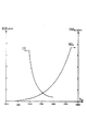
NOxおよびCOの発生を減らす最適温度範囲は、したがって約1650Kから1750Kの範囲にある。図1に、(COおよびNOx)カーブを用い、ガスタービン燃焼チャンバーの作動条件下における温度T(単位K)の関数として対応する一酸化炭素および窒素酸化物の発生を示す。
【0007】
したがって、NOxおよびCOの発生は燃焼チャンバー中の空気−燃料混合比、すなわち燃料流に流れ込む空気流の比と直接関係がある。上記のようにある温度範囲内で作動させようとして、混合気体の空気−燃料比を設定する必要がある場合、混合気体の断熱燃焼温度は混合比にほぼ比例して変動する。
【0008】
従来、よく知られているように、タービンの作動条件を制御できるパラメータは燃料流のみである。燃料の流れが一定であると仮定すると、空気流は装置の特性、特に炉における流れの断面積(cross−section)のみに依存する値に厳密に設定される。したがって、混合比はそれによって完全に規定される。
【0009】
しかし、上記のように規定した温度範囲が得られる混合比は、装置の特性カーブによって強制的に決まる混合比に対応するとは限らない。
【0010】
この問題を解決するためには、いくつかの構想が心に浮かぶ。
【0011】
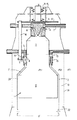
その一つは連続的に点火を行って、数段階で燃焼を行うことである。この公知の解決策は、図2に示すように、パイロット段階およびその後にさらに2つの段階からなり、各段階に空気取入口と例えば天然ガス等の燃料取入口を設けた燃焼チャンバーである。そして各段階で連続的に、かつ必要な総出力にしたがって、燃焼を行う。パイロット燃焼は、回転数のいかんを問わず行う。この解決策によって、理論的には十分な数の段階が設けてある限り、各エンジン回転数について点火段階で許容可能な混合比が得られる。主な欠点は、複雑な燃料供給サーキットを必要とし、したがって信頼性、制御および経費に問題があることである。
【0012】
第2の構想は、所定の温度範囲で燃焼チャンバーが作動するように、炉における空気流を制御する一連のシャッター、クラッパーまたはその他の遮断手段を設けることである。もちろん、これら要素の制御および作動は複雑であり、実施するのが困難である。さらに経費も高くなる。
【0013】
【発明が解決しようとする課題】
したがって、本発明はガスタービン燃焼チャンバーにおける混合ガス比制御の問題を、信頼性が高く、かつ簡単に解決することのできる燃焼チャンバーを提案することを目的とする。
【0014】
この制御の目的は、特に一酸化炭素および窒素酸化物の放出に関して、最適温度範囲で燃焼を行うことができるようにすることである。
【0015】
【課題を解決するための手段】
本発明の対象は、少なくとも第一のパイロット燃料注入手段と、関連する第一の酸化剤注入手段とが開口したパイロット注入領域と称する少なくとも一つの領域と、少なくとも第二の主燃料注入手段と、関連する第二の酸化剤注入手段とが開口した主燃焼領域とを有し、これらの全てが囲い内の内圧P2下に保たれているガスタービン燃焼チャンバーである。
【0016】
本発明によれば、前記燃焼チャンバーは、エンジン回転数と直接関連する、内圧(P2)と囲いの外の大気圧(P0)の差圧に反応して酸化剤の第二の流れを制御する機械的な制御手段をさらに有している。
【0017】
さらに詳細に述べると、前記制御手段は燃焼チャンバー内の第二の空気取入口をふさぎ、ふさぎ量を増減する少なくとも一つの遮断部材と、遮断部材と支持部材の間に設けたいくつかのタイロッドと、圧縮部材と、圧縮部材の周囲に設けられ、支持部材と共に、大気圧(P0)の体積部分と圧力(P2)下の囲い内との間を仕切るベローズジョイントと、を有している。
【0018】
特に、第一の燃料注入手段と第一の酸化剤注入手段は、燃焼チャンバーの縦軸(XX’)に実質的に隣接して設けられている。
【0019】
本発明の具体的な構成によると、第二の主燃料注入手段と第二の酸化剤注入手段は、炎の伝播する方向に対してパイロット燃焼領域から下流の外周上に設けられている。
【0020】
さらに、本発明に係わる燃焼チャンバーは、炎の伝播する方向に対して第二の酸化剤注入手段の下流で燃焼チャンバー内に開口する第三の酸化剤注入手段を有している。
【0021】
さらに、酸化剤の第二の流れを制御する手段は、第三の空気注入手段の流れを制御する(バイパス機能)。
【0022】
圧縮部材は、積み重ねられたワッシャーまたはスプリングを有している。
【0023】
本発明の一実施態様によると、チャンバーは、それぞれ第二の主燃料注入手段(7)と主酸化剤注入手段(8)が一緒になったグループとして設けられている3つの領域を有し、これらの各領域が互いに120°離れて設けてある。
【0024】
【発明の実施の形態】
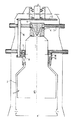
本発明のその他の利点、特徴および詳細は、非限定的な例として添付の図面を参照して以下の詳細な説明を読むことによって明らかになる。ここで、図3は、本発明の実施形態に従う燃焼チャンバーの縦断図である。図4は、他の作動位置にある、図3に示した燃焼チャンバーを示す縦断面である。
【0025】
図3において、炉1は部分的に直径の異なる内殻2で区切られ、直径の小さい部分にはパイロット燃焼領域11が設けられ、直径の大きい部分12は主燃焼領域となっている。
【0026】
パイロット燃焼領域11は無負荷回転数で燃焼を発生し、作動回転数が変わってもここに燃焼を保つことができる。
【0027】
例えば天然ガス等の燃料を供給するインジェクタ3および空気インジェクタまたは空気取入口4は、それぞれ領域11に開口している。
【0028】
領域11を仕切るため、底5が設けてある。燃料取入口3および空気取入口4は、底5の近くで、チャンバーの縦軸XX’の周囲に、かつ縦軸XX’から遠くない所に設けてある。パイロット燃焼領域11は炎安定化領域であり、作動条件に関係なく、そこには炎が存在している。
【0029】
空気に回転運動を与えるブレード6を、空気取入口4の近くに設けてもよい。
【0030】
燃料インジェクタ3は、本発明の範囲から逸脱することなく、これらのブレードに設けてもよい。
【0031】
領域11ならびに領域12は、所定の圧力下にある。
【0032】
したがって、領域12は領域11よりも直径が大きい。主燃焼は、この領域で行われる。
【0033】
したがって、第二の燃料インジェクタ7は、領域11と12の間に設ける。同様に、第二の空気インジェクタ8は、第二の燃料インジェクタ7の近くに設ける。ブレード9は、インジェクタ8の近くに配置してもよい。手段7、8および9は内殻2の周囲に設け、いくつかのグループとして設けることができる。ここでは3つのグループをそれぞれ120°離して設けてある。
【0034】
さらに、“希釈空気”と称する空気、すなわち燃焼または壁の冷却に使用しない空気を、適切な開口部22から燃焼領域12の下流で内殻2内に導入することもできる。
【0035】
一般的な空気の供給は、内殻2と外殻14で仕切られた環状空間13を通して行う。この空間は圧力P2の下にあり、この圧力は圧力P1よりも若干高く、この差は各種の空気取入口によって生じる圧力損失によるものである。
【0036】
本発明によると、空気取入口8の近くには環状空間(P2)と囲い14外(ここでは大気圧に等しい圧力P0下にある)の間の差圧に反応する流量制御手段を設ける。
【0037】
タービンの回転速度が高くなると、圧力P2が高くなり、圧力P0は変化しない。したがって、差圧(P2−P0)は増大し、流量制御手段が反応し、空気取入口8を広げる。
【0038】
さらに詳細に述べると、流量制御手段は開口部8(望ましくはブレード9を設ける)を通りすぎて軸XX’に沿ってスライドするシェルリング15からなり、それによって空気流の断面積を変えることができる。
【0039】
対応する開口部が、内殻2上の開口部8に対向するようにシェルリング15に設けられている。
【0040】
シェルリング15は、公知の手段によって、いくつかのロッド16の下端に固定されている。ロッド16の他端の所でロッド16は、圧縮部材18に接続した保持板17を支持している。そこに、積み重ねられた円錐形のワッシャーまたはスプリングを設けてもよい。
【0041】
さらに、ベローズ19またはその他の密封手段を、圧縮手段18の周囲に設ける。ベローズ19は燃焼チャンバーの内側(圧力P2およびP1の下にある)と外側(圧力P0の下にある)の間を分離している。
【0042】
さらに、シェルリング15に空間13と内殻2の内側の環状空間21とを通じさせる別の開口部を設けてもよい。したがって、内殻2と同軸の別の殻20を内殻2の高さの一部に設けてもよい。
【0043】
殻20の高さは、燃焼領域12の高さに対応させることもできる。この高さにわたって設けることによって、開口部10を通って取り込まれ、環状空間21を通過する空気は、燃焼領域12から下流に排出することができ、同時に、前記燃焼領域12の壁を冷却することができる。したがって、負荷のいかんを問わず、主炉中に許容可能な混合比が保たれる。バイパス21の主たる作用は、特に部分負荷のときに炉1における混合比の低下を制限することである。
【0044】
開口部10は、全負荷のときそこを空気が通過せず(図4の例)、部分負荷すなわち負荷が低いとき、燃焼領域12から下流に排出し、同時に、シェル2の壁を冷却するために、ある程度の空気が空間21に流入するように構成されている。
【0045】
それぞれ図3と4を比較することによって、上記のアセンブリの作動は以下のように要約される。
【0046】
実際には、図3では、各種部材の位置がその最大能力の約50%の作動に相当している。図4は、その能力の100%で作動している装置を示す。
【0047】
低い出力が必要な場合(無負荷回転数)は、環状空間13と囲い14の外側間の相対圧力(P2−P0)のために、空気取入口8の開度を制限することができる。
【0048】
同時に、開口部10は比較的広く開けられ、したがって空気は領域12の燃焼に関与することなく、空間21を流れ、壁20を冷却する。したがって、ここで許容できる混合比を保つことができ、排気中のCOの増加を避けることができる。
【0049】
タービンが全負荷で作動している時には、上記の場合よりも相対圧力(P2−P0)が高く、したがってシェルリング15が持ち上がり、開口部8が広く開く。したがって、多量の空気が燃焼領域12に流入する。同時に、開口部10が閉じ、環状空間21に流入する空気を遮断する。したがって、多量の空気が直接主燃焼領域12に注入され、それによって最高混合比が制限され、COの生成が防止される。
【0050】
したがって、本発明に係わる燃焼チャンバーは、空気流の制御に特殊な機械的装置を必要としない。制御は燃焼チャンバーの相対的圧力により、したがってエンジンの回転数により自動的に行われる。
【0051】
【発明の効果】
本発明は、燃焼空気流の自動的な制御が可能である。機械的制御システムが、きわめて限られた数の機械部品によって得られるという利点がある。
【図面の簡単な説明】
【図1】 COおよびNOxの排出濃度を作動中のガスタービンの燃焼チャンバー内の温度の函数として表した図である。
【図2】 パイロット燃焼とそれに続く第1、第2の燃焼段階を有する従来のガスタービン燃焼チャンバーの一例を示す断面図である。
【図3】 本発明のある作動状態のガスタービン燃焼チャンバーの一例を示す断面図である。
【図4】 図3のチャンバーの、他の作動状態を示す断面図である。
【符号の説明】
1 炉
2 内殻
3 第1パイロット燃料インジェクタ(注入手段)(燃料取入口)
4 第1酸化剤注入手段(空気インジエクターまたは空気取入口)
5 底
6 ブレード
7 第2主燃料インジェクタ
8 第2酸化剤インジェクタ(第2酸化剤取入口)
9 ブレード
10 開口
11 パイロット燃焼領域
12 主燃焼領域
13 環状空間
14 外殻(囲い)
15 シェルリング(遮断部材)
16 ロッド
17 支持板(支持部材)
18 圧縮部材
19 ベローズ(ベローズジョイント)
20 殻(冷却壁)
21 環状空間
22 オリフィス
P0 大気圧
P1 内部圧(燃焼ゾーンの圧)
P2 環状空間13の圧
XX’ 縦軸[0001]
BACKGROUND OF THE INVENTION
The present invention relates to the field of gas turbines, particularly the combustion chambers associated with such turbines.
[0002]
[Prior art]
A problem that exists at the basis of the present invention is the contamination that occurs when these turbines are operated. More precisely, nitrogen oxides (NOx) and carbon monoxide (CO) are very harmful to the environment and their emissions need to be reduced.
[0003]
Moreover, in industrialized countries, fairly strict regulations are or are about to be implemented.
[0004]
Nitrogen oxide (NOx) is the main thermal nitrogen oxide and is produced at high temperatures, for example, 1700 K or higher, in a gas turbine combustion chamber where the fume residence time is typically 2 to 10 milliseconds.
[0005]
Carbon monoxide (CO) is produced by incomplete combustion of the fuel at low temperatures (<1600K).
[0006]
The optimum temperature range that reduces the generation of NOx and CO is therefore in the range of about 1650K to 1750K. FIG. 1 shows the corresponding carbon monoxide and nitrogen oxide evolution as a function of temperature T (unit K) under the operating conditions of the gas turbine combustion chamber using (CO and NOx) curves.
[0007]
Therefore, the generation of NOx and CO is directly related to the air-fuel mixture ratio in the combustion chamber, i.e. the ratio of the airflow flowing into the fuel stream. By trying to operate within a temperature range which is as described above, air in the mixed gas - if it is necessary to set the fuel ratio, adiabatic combustion temperature of the mixed gas varies substantially proportional to the mixing ratio.
[0008]
Conventionally, as is well known, the fuel flow is the only parameter that can control the operating conditions of the turbine. Assuming that the fuel flow is constant, the air flow is strictly set to a value that depends only on the characteristics of the device, in particular the flow cross-section in the furnace. Therefore, the mixing ratio is thereby completely defined.
[0009]
However, the mixing ratio that provides the temperature range specified as described above does not necessarily correspond to the mixing ratio that is forcibly determined by the characteristic curve of the apparatus.
[0010]
Several ideas come to mind to solve this problem.
[0011]
One is subjected to a continuous ignition is to perform the combustion in several steps. This known solution, as shown in FIG. 2, is a combustion chamber comprising a pilot stage and then two further stages, each stage having an air inlet and a fuel inlet such as natural gas. Combustion is performed continuously at each stage and according to the required total output. Pilot combustion is performed regardless of the rotational speed. This solution provides an acceptable mixing ratio in the ignition stage for each engine speed as long as a sufficient number of stages are theoretically provided. The main drawback is that it requires a complex fuel supply circuit and thus problems in reliability, control and cost.
[0012]
The second concept is to provide a series of shutters, clappers or other shut-off means that control the air flow in the furnace so that the combustion chamber operates at a predetermined temperature range. Of course, the control and operation of these elements is complex and difficult to implement. In addition, the cost will be higher.
[0013]
[Problems to be solved by the invention]
Accordingly, an object of the present invention is to propose a combustion chamber that can solve the problem of mixed gas ratio control in a gas turbine combustion chamber with high reliability and can be easily solved.
[0014]
The purpose of this control is to allow combustion to occur in the optimum temperature range, particularly with respect to carbon monoxide and nitrogen oxide emissions.
[0015]
[Means for Solving the Problems]
The subject of the present invention is at least one region referred to as a pilot injection region opened by at least a first pilot fuel injection means and an associated first oxidant injection means, at least a second main fuel injection means, A gas turbine combustion chamber in which the associated second oxidant injection means has an open main combustion region, all of which are maintained under an internal pressure P2 in the enclosure.
[0016]
According to the present invention, the combustion chamber controls the second flow of oxidant in response to the differential pressure between the internal pressure ( P2 ) and the atmospheric pressure (P0) outside the enclosure, which is directly related to the engine speed. It further has mechanical control means.
[0017]
More specifically, the control means closes the second air intake in the combustion chamber, and includes at least one blocking member for increasing or decreasing the blocking amount, and several tie rods provided between the blocking member and the support member. And a compression member, and a bellows joint provided around the compression member and partitioning between the volume portion of the atmospheric pressure (P0) and the enclosure under the pressure ( P2 ) together with the support member.
[0018]
In particular, the first fuel injection means and the first oxidant injection means are provided substantially adjacent to the longitudinal axis (XX ′) of the combustion chamber.
[0019]
According to the specific configuration of the present invention, the second main fuel injection means and the second oxidant injection means are provided on the outer periphery downstream from the pilot combustion region in the flame propagation direction.
[0020]
Furthermore, the combustion chamber according to the present invention, that has a third oxidant injection means for the second opening into the combustion chamber downstream of the oxidizer injection means relative to the propagation direction of the flame.
[0021]
Further, it means for controlling the second flow of acid agent controls the flow of the third air injection means (bypass function).
[0022]
Compression member, that have a washer or spring stacked.
[0023]
According to one embodiment of the present invention, the chamber has three regions, each second main fuel injection means (7) and the main oxidant injection means (8) is provided as a group together, These regions are provided 120 ° apart from each other .
[0024]
DETAILED DESCRIPTION OF THE INVENTION
Other advantages, features and details of the present invention will become apparent upon reading the following detailed description with reference to the accompanying drawings by way of non-limiting example. Here, FIG. 3 is a longitudinal sectional view of a combustion chamber according to an embodiment of the present invention. Figure 4 is in other operating position, is a longitudinal section showing the combustion chamber over that shown in FIG.
[0025]
3, furnace 1 is separated by the
[0026]
[0027]
For example, an injector 3 for supplying a fuel such as natural gas and an air injector or an air intake 4 open in the
[0028]
A
[0029]
A blade 6 that imparts rotational motion to the air may be provided near the air intake 4.
[0030]
Fuel injectors 3 may be provided on these blades without departing from the scope of the present invention.
[0031]
[0032]
Therefore, the
[0033]
Therefore, the second fuel injector 7 is provided between the
[0034]
Furthermore, the air called "dilution air", i.e. the air which is not used for cooling the combustion or wall, may be introduced into the inner shell in 2 downstream of the
[0035]
A general supply of air is performed through an
[0036]
According to the invention, a flow rate control means is provided near the air intake 8 which reacts to the differential pressure between the annular space (P2) and the outside of the enclosure 14 (here under pressure P0 equal to atmospheric pressure).
[0037]
When the rotational speed of the turbine increases, the pressure P2 increases and the pressure P0 does not change. Therefore, the differential pressure (P2-P0) increases, the flow rate control means reacts, and the air intake 8 is expanded.
[0038]
In more detail, the flow control means comprises a
[0039]
Corresponding openings, that are provided in the
[0040]
[0041]
Further, bellows 19 or other sealing means, disposed around the compression means 18. Bellows 19 are separated between the outer and inner combustion chamber (under the pressure P2 and P1) (under the pressure P0).
[0042]
Further, another opening that let through the inner
[0043]
The height of the
[0044]
Opening 10 therethrough when the full load without passing through the air (the example of FIG. 4), when parts partial load or load is low, discharged downstream from the
[0045]
By comparing FIG. 3, respectively and a 4, operation of the assembly is Ru are summarized as follows.
[0046]
In fact, in Figure 3, the position of the various members that corresponded to the operation of approximately 50% of its maximum capacity. Figure 4 shows an apparatus that are operated at 100% of its capacity.
[0047]
If low output is required (no-load rotational speed) can be limited due to the relative pressure between the outer 14 enclosure with the annular space 13 (P2-P0), the opening of the air inlet 8.
[0048]
At the same time, the opening 10 is opened wide relatively, thus the air is not to be involved in the
[0049]
Sometimes turbine you are operating at full load, relative pressure than in the case of the above (P2-P0) is high, thus lifting the
[0050]
Therefore, the combustion chamber according to the present invention does not require a special mechanical device for air flow control. Control is performed automatically by the relative pressure of the combustion chamber and thus by the engine speed.
[0051]
【The invention's effect】
The present invention allows automatic control of the combustion air flow. Mechanical control system, there is an advantage that is obtained depending on a very limited number of mechanical parts products.
[Brief description of the drawings]
1 is a diagram showing the emission concentration of CO and NOx as a temperature function of the combustion chamber of a gas turbine during operation.
FIG. 2 is a cross-sectional view illustrating an example of a conventional gas turbine combustion chamber having pilot combustion followed by first and second combustion stages.
FIG. 3 is a cross-sectional view showing an example of a gas turbine combustion chamber in an operating state of the present invention.
4 is a cross-sectional view showing another operating state of the chamber of FIG. 3;
[Explanation of symbols]
1
4 First oxidant injection means (air injector or air intake)
5 Bottom 6 Blade 7 Second main fuel injector 8 Second oxidant injector (second oxidant intake)
9 Blade 10
15 Shell ring ( blocking member )
16
18
20 shells (cooling wall)
21
P2 pressure in annular space XX 'vertical axis
Claims (9)
エンジンの回転数に直接関連する、前記囲い(14)内の前記圧力(P2)と前記囲いの外の大気圧(P0)との差圧に反応する、酸化剤の第二の流れを制御する機械的な制御手段(15、16、17、18、19)をさらに有することを特徴とする燃焼チャンバー。At least one region (11) referred to as a pilot combustion region open with at least a first pilot fuel injection means (3) and an associated first oxidant injection means (4), and at least a second main fuel injection Means (7) and an associated second oxidant injection means (8) having an open main combustion region (12), all of which are maintained at the pressure (P2) in the enclosure (14). In a leaning gas turbine combustion chamber,
Controls a second flow of oxidant that is directly related to engine speed and reacts to the pressure difference between the pressure (P2 ) in the enclosure (14) and the atmospheric pressure (P0) outside the enclosure. A combustion chamber further comprising mechanical control means (15, 16, 17, 18, 19).
Applications Claiming Priority (2)
| Application Number | Priority Date | Filing Date | Title |
|---|---|---|---|
| FR9807409 | 1998-06-11 | ||
| FR9807409A FR2779807B1 (en) | 1998-06-11 | 1998-06-11 | VARIABLE GEOMETRY GAS TURBINE COMBUSTION CHAMBER |
Publications (3)
| Publication Number | Publication Date |
|---|---|
| JP2000009319A JP2000009319A (en) | 2000-01-14 |
| JP2000009319A5 JP2000009319A5 (en) | 2006-07-27 |
| JP4435331B2 true JP4435331B2 (en) | 2010-03-17 |
Family
ID=9527308
Family Applications (1)
| Application Number | Title | Priority Date | Filing Date |
|---|---|---|---|
| JP16130699A Expired - Lifetime JP4435331B2 (en) | 1998-06-11 | 1999-06-08 | Variable throat gas turbine combustion chamber |
Country Status (5)
| Country | Link |
|---|---|
| US (1) | US6263663B1 (en) |
| EP (1) | EP0964206B1 (en) |
| JP (1) | JP4435331B2 (en) |
| DE (1) | DE69922437T2 (en) |
| FR (1) | FR2779807B1 (en) |
Families Citing this family (14)
| Publication number | Priority date | Publication date | Assignee | Title |
|---|---|---|---|---|
| US7788897B2 (en) * | 2004-06-11 | 2010-09-07 | Vast Power Portfolio, Llc | Low emissions combustion apparatus and method |
| JP4670035B2 (en) * | 2004-06-25 | 2011-04-13 | 独立行政法人 宇宙航空研究開発機構 | Gas turbine combustor |
| JP2007113888A (en) * | 2005-10-24 | 2007-05-10 | Kawasaki Heavy Ind Ltd | Combustor structure of gas turbine engine |
| US8915086B2 (en) | 2006-08-07 | 2014-12-23 | General Electric Company | System for controlling combustion dynamics and method for operating the same |
| GB0815761D0 (en) * | 2008-09-01 | 2008-10-08 | Rolls Royce Plc | Swirler for a fuel injector |
| US8099941B2 (en) * | 2008-12-31 | 2012-01-24 | General Electric Company | Methods and systems for controlling a combustor in turbine engines |
| US8276386B2 (en) * | 2010-09-24 | 2012-10-02 | General Electric Company | Apparatus and method for a combustor |
| US9316155B2 (en) * | 2013-03-18 | 2016-04-19 | General Electric Company | System for providing fuel to a combustor |
| US9803555B2 (en) * | 2014-04-23 | 2017-10-31 | General Electric Company | Fuel delivery system with moveably attached fuel tube |
| FR3065059B1 (en) | 2017-04-11 | 2020-11-06 | Office National Detudes Rech Aerospatiales | SELF-ADAPTIVE VARIABLE GEOMETRY GAS TURBINE FIREPLACE |
| US20230332544A1 (en) * | 2020-10-14 | 2023-10-19 | King Abdullah University Of Science And Technology | Adjustable fuel injector for flame dynamics control |
| GB202112641D0 (en) * | 2021-09-06 | 2021-10-20 | Rolls Royce Plc | Controlling soot |
| CN116592391A (en) * | 2022-02-07 | 2023-08-15 | 通用电气公司 | Burner with variable primary zone combustion chamber |
| CN115031260B (en) * | 2022-05-30 | 2023-08-22 | 中国人民解放军空军工程大学 | Adjustable spray pipe with fixed position of outlet throat of rotary detonation combustion chamber |
Family Cites Families (7)
| Publication number | Priority date | Publication date | Assignee | Title |
|---|---|---|---|---|
| US3691761A (en) * | 1967-11-10 | 1972-09-19 | Squire Ronald Jackson | Apparatus for regulation of airflow to flame tubes for gas turbine engines |
| DE2020416A1 (en) * | 1970-04-27 | 1971-11-11 | Motoren Turbinen Union | Combustion chamber for gas turbine engines |
| US3869246A (en) * | 1973-12-26 | 1975-03-04 | Gen Motors Corp | Variable configuration combustion apparatus |
| FR2270448A1 (en) * | 1974-05-10 | 1975-12-05 | Bennes Marrel | Gas turbine combustion chamber - has spring loaded bellows controlling annular air flow control membrane |
| US4296599A (en) * | 1979-03-30 | 1981-10-27 | General Electric Company | Turbine cooling air modulation apparatus |
| JP2644745B2 (en) * | 1987-03-06 | 1997-08-25 | 株式会社日立製作所 | Gas turbine combustor |
| FR2661714B1 (en) * | 1990-05-03 | 1994-06-17 | Snecma | DEVICE FOR SUPPLYING FUEL TO A GAS TURBINE. |
-
1998
- 1998-06-11 FR FR9807409A patent/FR2779807B1/en not_active Expired - Lifetime
-
1999
- 1999-05-18 DE DE69922437T patent/DE69922437T2/en not_active Expired - Lifetime
- 1999-05-18 EP EP99401204A patent/EP0964206B1/en not_active Expired - Lifetime
- 1999-06-08 JP JP16130699A patent/JP4435331B2/en not_active Expired - Lifetime
- 1999-06-11 US US09/330,199 patent/US6263663B1/en not_active Expired - Lifetime
Also Published As
| Publication number | Publication date |
|---|---|
| DE69922437T2 (en) | 2005-12-08 |
| FR2779807B1 (en) | 2000-07-13 |
| EP0964206B1 (en) | 2004-12-08 |
| FR2779807A1 (en) | 1999-12-17 |
| US6263663B1 (en) | 2001-07-24 |
| JP2000009319A (en) | 2000-01-14 |
| EP0964206A1 (en) | 1999-12-15 |
| DE69922437D1 (en) | 2005-01-13 |
Similar Documents
| Publication | Publication Date | Title |
|---|---|---|
| JP4435331B2 (en) | Variable throat gas turbine combustion chamber | |
| US4380895A (en) | Combustion chamber for a gas turbine engine having a variable rate diffuser upstream of air inlet means | |
| US4192139A (en) | Combustion chamber for gas turbines | |
| JP4658471B2 (en) | Method and apparatus for reducing combustor emissions in a gas turbine engine | |
| US5127229A (en) | Gas turbine combustor | |
| US6698206B2 (en) | Combustion chamber | |
| US6332313B1 (en) | Combustion chamber with separate, valved air mixing passages for separate combustion zones | |
| US20020043067A1 (en) | Gas turbine combustion system and combustion control method therefor | |
| US5081843A (en) | Combustor for a gas turbine | |
| US4446692A (en) | Fluidic control of airflow in combustion chambers | |
| JPH06510361A (en) | Low harmful emissions combustion nozzle for gas turbine engines | |
| GB2280022A (en) | Gas turbine combustor | |
| US20140083105A1 (en) | Gas turbine combustor | |
| CN109708147B (en) | Involute standing vortex burner assembly | |
| KR20160092939A (en) | Sequential combustor arrangement with a mixer | |
| JPS5845413A (en) | Fuel injection device for gas turbine engine | |
| JP2000009319A5 (en) | ||
| JPS6361723A (en) | Catalytic combustion device | |
| JP3030041B2 (en) | Combustor | |
| JP2003074856A (en) | Combustion equipment of gas-turbine engine | |
| US5285630A (en) | System for reducing nitrogen-oxide emissions from a gas turbine engine | |
| US6508061B2 (en) | Diffuser combustor | |
| US5398495A (en) | Combustion chamber with variable oxidizer intakes | |
| JP2729748B2 (en) | Gas turbine combustion method and apparatus | |
| JPH04131619A (en) | Gas turbine combustion device |
Legal Events
| Date | Code | Title | Description |
|---|---|---|---|
| A521 | Request for written amendment filed |
Free format text: JAPANESE INTERMEDIATE CODE: A523 Effective date: 20060608 |
|
| A621 | Written request for application examination |
Free format text: JAPANESE INTERMEDIATE CODE: A621 Effective date: 20060608 |
|
| RD03 | Notification of appointment of power of attorney |
Free format text: JAPANESE INTERMEDIATE CODE: A7423 Effective date: 20060608 |
|
| A131 | Notification of reasons for refusal |
Free format text: JAPANESE INTERMEDIATE CODE: A131 Effective date: 20080917 |
|
| A521 | Request for written amendment filed |
Free format text: JAPANESE INTERMEDIATE CODE: A523 Effective date: 20081217 |
|
| A131 | Notification of reasons for refusal |
Free format text: JAPANESE INTERMEDIATE CODE: A131 Effective date: 20090520 |
|
| A601 | Written request for extension of time |
Free format text: JAPANESE INTERMEDIATE CODE: A601 Effective date: 20090820 |
|
| A602 | Written permission of extension of time |
Free format text: JAPANESE INTERMEDIATE CODE: A602 Effective date: 20090825 |
|
| TRDD | Decision of grant or rejection written | ||
| A01 | Written decision to grant a patent or to grant a registration (utility model) |
Free format text: JAPANESE INTERMEDIATE CODE: A01 Effective date: 20091125 |
|
| A01 | Written decision to grant a patent or to grant a registration (utility model) |
Free format text: JAPANESE INTERMEDIATE CODE: A01 |
|
| A61 | First payment of annual fees (during grant procedure) |
Free format text: JAPANESE INTERMEDIATE CODE: A61 Effective date: 20091224 |
|
| R150 | Certificate of patent or registration of utility model |
Ref document number: 4435331 Country of ref document: JP Free format text: JAPANESE INTERMEDIATE CODE: R150 Free format text: JAPANESE INTERMEDIATE CODE: R150 |
|
| FPAY | Renewal fee payment (event date is renewal date of database) |
Free format text: PAYMENT UNTIL: 20130108 Year of fee payment: 3 |
|
| R250 | Receipt of annual fees |
Free format text: JAPANESE INTERMEDIATE CODE: R250 |
|
| S111 | Request for change of ownership or part of ownership |
Free format text: JAPANESE INTERMEDIATE CODE: R313117 |
|
| S533 | Written request for registration of change of name |
Free format text: JAPANESE INTERMEDIATE CODE: R313533 |
|
| R350 | Written notification of registration of transfer |
Free format text: JAPANESE INTERMEDIATE CODE: R350 |
|
| R250 | Receipt of annual fees |
Free format text: JAPANESE INTERMEDIATE CODE: R250 |
|
| R250 | Receipt of annual fees |
Free format text: JAPANESE INTERMEDIATE CODE: R250 |
|
| R250 | Receipt of annual fees |
Free format text: JAPANESE INTERMEDIATE CODE: R250 |
|
| R250 | Receipt of annual fees |
Free format text: JAPANESE INTERMEDIATE CODE: R250 |
|
| R250 | Receipt of annual fees |
Free format text: JAPANESE INTERMEDIATE CODE: R250 |
|
| R250 | Receipt of annual fees |
Free format text: JAPANESE INTERMEDIATE CODE: R250 |
|
| EXPY | Cancellation because of completion of term |