JP4434032B2 - Droplet ejection apparatus control method, droplet ejection apparatus, and electro-optic device manufacturing method - Google Patents
Droplet ejection apparatus control method, droplet ejection apparatus, and electro-optic device manufacturing method Download PDFInfo
- Publication number
- JP4434032B2 JP4434032B2 JP2005039494A JP2005039494A JP4434032B2 JP 4434032 B2 JP4434032 B2 JP 4434032B2 JP 2005039494 A JP2005039494 A JP 2005039494A JP 2005039494 A JP2005039494 A JP 2005039494A JP 4434032 B2 JP4434032 B2 JP 4434032B2
- Authority
- JP
- Japan
- Prior art keywords
- functional liquid
- pressure
- droplet ejection
- ejection head
- liquid droplet
- Prior art date
- Legal status (The legal status is an assumption and is not a legal conclusion. Google has not performed a legal analysis and makes no representation as to the accuracy of the status listed.)
- Active
Links
Images


Classifications
-
- B—PERFORMING OPERATIONS; TRANSPORTING
- B41—PRINTING; LINING MACHINES; TYPEWRITERS; STAMPS
- B41J—TYPEWRITERS; SELECTIVE PRINTING MECHANISMS, i.e. MECHANISMS PRINTING OTHERWISE THAN FROM A FORME; CORRECTION OF TYPOGRAPHICAL ERRORS
- B41J29/00—Details of, or accessories for, typewriters or selective printing mechanisms not otherwise provided for
- B41J29/38—Drives, motors, controls or automatic cut-off devices for the entire printing mechanism
- B41J29/393—Devices for controlling or analysing the entire machine ; Controlling or analysing mechanical parameters involving printing of test patterns
-
- B—PERFORMING OPERATIONS; TRANSPORTING
- B41—PRINTING; LINING MACHINES; TYPEWRITERS; STAMPS
- B41J—TYPEWRITERS; SELECTIVE PRINTING MECHANISMS, i.e. MECHANISMS PRINTING OTHERWISE THAN FROM A FORME; CORRECTION OF TYPOGRAPHICAL ERRORS
- B41J2/00—Typewriters or selective printing mechanisms characterised by the printing or marking process for which they are designed
- B41J2/005—Typewriters or selective printing mechanisms characterised by the printing or marking process for which they are designed characterised by bringing liquid or particles selectively into contact with a printing material
- B41J2/01—Ink jet
- B41J2/07—Ink jet characterised by jet control
-
- B—PERFORMING OPERATIONS; TRANSPORTING
- B41—PRINTING; LINING MACHINES; TYPEWRITERS; STAMPS
- B41J—TYPEWRITERS; SELECTIVE PRINTING MECHANISMS, i.e. MECHANISMS PRINTING OTHERWISE THAN FROM A FORME; CORRECTION OF TYPOGRAPHICAL ERRORS
- B41J2/00—Typewriters or selective printing mechanisms characterised by the printing or marking process for which they are designed
- B41J2/005—Typewriters or selective printing mechanisms characterised by the printing or marking process for which they are designed characterised by bringing liquid or particles selectively into contact with a printing material
- B41J2/01—Ink jet
- B41J2/17—Ink jet characterised by ink handling
- B41J2/175—Ink supply systems ; Circuit parts therefor
- B41J2/17503—Ink cartridges
- B41J2/17543—Cartridge presence detection or type identification
- B41J2/17546—Cartridge presence detection or type identification electronically
-
- B—PERFORMING OPERATIONS; TRANSPORTING
- B41—PRINTING; LINING MACHINES; TYPEWRITERS; STAMPS
- B41J—TYPEWRITERS; SELECTIVE PRINTING MECHANISMS, i.e. MECHANISMS PRINTING OTHERWISE THAN FROM A FORME; CORRECTION OF TYPOGRAPHICAL ERRORS
- B41J2/00—Typewriters or selective printing mechanisms characterised by the printing or marking process for which they are designed
- B41J2/005—Typewriters or selective printing mechanisms characterised by the printing or marking process for which they are designed characterised by bringing liquid or particles selectively into contact with a printing material
- B41J2/01—Ink jet
- B41J2/17—Ink jet characterised by ink handling
- B41J2/175—Ink supply systems ; Circuit parts therefor
- B41J2/17503—Ink cartridges
- B41J2/17556—Means for regulating the pressure in the cartridge
Description
本発明は、加圧ポンプの間欠駆動により、所定の作動圧力範囲を維持するように機能液タンクを加圧して、機能液タンクから機能液滴を吐出する機能液滴吐出ヘッドに機能液の加圧供給を行う加圧供給動作と、描画領域にセットされた描画対象物に対して、機能液滴吐出ヘッドを相対的に移動させながら、機能液滴吐出ヘッドを駆動することにより機能液滴を吐出させて、描画を行う描画動作と、を実行する液滴吐出装置の制御方法、液滴吐出装置、電気光学装置の製造方法に関する。 According to the present invention, the functional liquid tank is pressurized by intermittent driving of the pressurizing pump so as to maintain a predetermined operating pressure range, and the functional liquid is applied to the functional liquid droplet ejection head that ejects the functional liquid droplets from the functional liquid tank. The functional liquid droplet discharge head is driven by moving the functional liquid droplet discharge head while moving the functional liquid droplet discharge head relative to the drawing target set in the drawing area. by discharging relates the control method of the droplet discharge device to perform a drawing operation to draw a droplet ejection apparatus, the manufacturing how the electro-optical device.
液滴吐出装置の一種として知られる従来のインクジェット記録装置(液滴吐出装置)の中には、エアーポンプを用いてインクタンク(機能液タンク)を加圧することにより、インクタンクに貯留されたインク(機能液)を、インクジェット記録ヘッド(機能液滴吐出ヘッド)に加圧供給するインク供給装置(機能液供給装置)を備えたものがある。 In a conventional ink jet recording apparatus (droplet discharge apparatus) known as a kind of droplet discharge apparatus, ink stored in an ink tank is pressurized by pressurizing an ink tank (functional liquid tank) using an air pump. Some have an ink supply device (functional liquid supply device) that pressurizes and supplies (functional liquid) to an inkjet recording head (functional liquid droplet ejection head).
インク供給装置では、インクタンクとインクジェット記録ヘッドとの間にサブタンクが介設されており、インクタンクから圧送されたインクは一旦サブタンクに貯留されてから、インクジェット記録ヘッドに供給されるようになっている。サブタンクには、インク残量を検出する変位検出手段が設けられており、サブタンク内のインク残量に応じて、インクタンクからインクが供給される。これにより、サブタンク内の圧力は一定の範囲に保たれ、インクジェット記録ヘッドに供給されるインクの圧力変動が抑えられるようになっている。
そして、従来のインクジェット記録装置は、変位検出手段がある一定値を検出すると、インクタンクから機能液が加圧供給される構成となっており、印刷中であっても、変位検出手段が一定値を検出すれば、インクジェット記録ヘッドにインクが加圧供給される。しかしながら、印刷中のインクジェット記録ヘッドにインクを加圧供給すると、加圧ポンプのON−OFFによりインクジェット記録ヘッド内のヘッド内流路に圧力変動(脈動)が生じ、インク滴の吐出が不安定になって、印刷品質に悪影響を及ぼす惧れが生じる。 The conventional ink jet recording apparatus is configured such that when the displacement detection means detects a certain value, the functional liquid is pressurized and supplied from the ink tank, and the displacement detection means remains constant even during printing. Is detected, ink is pressurized and supplied to the ink jet recording head. However, when pressure is supplied to the ink jet recording head during printing, pressure fluctuation (pulsation) occurs in the flow path in the ink jet recording head due to ON / OFF of the pressure pump, and ink droplet ejection becomes unstable. As a result, the print quality may be adversely affected.
そこで、本発明は、印刷品質を低下させることなく、機能液滴吐出ヘッドにインクを加圧供給することができる液滴吐出装置の制御方法、液滴吐出装置、電気光学装置の製造方法を提供することを課題としている。 The present invention, without reducing the printing quality control method for a droplet ejection apparatus in which the ink can be pressurized supply to the functional liquid droplet ejecting heads, the droplet discharge device, producing how the electro-optical device The issue is to provide.
本発明の液滴吐出装置の制御方法は、機能液滴吐出ヘッドから所定量の機能液滴を吐出させる作動圧力を維持しつつ機能液タンクを加圧して機能液タンクから機能液滴吐出ヘッドに機能液の加圧供給を行う加圧供給動作と、描画領域にセットされた描画対象物に対して、機能液滴吐出ヘッドを相対的に移動させながら、機能液滴吐出ヘッドを駆動することにより機能液滴を吐出させて、描画を行う描画動作と、を実行する液滴吐出装置の制御方法において、機能液タンク内の圧力が作動圧力の下限圧力以下か否かを検出する圧力検出工程と、機能液タンク内の圧力が下限圧力以下のときに、機能液滴吐出ヘッドが描画動作中であるか否かを確認する動作確認工程と、描画動作中でないと確認されたときに、機能液タンクを作動圧力の上限圧力まで加圧する第1加圧制御工程と、を備えたことを特徴とする。
The method of droplet ejection apparatus of the present invention, the functional droplet function the functional liquid tank while maintaining the operating pressure from the discharge head cause discharging the functional liquid droplet of a predetermined quantity pressurized fluid tank to the functional liquid droplet ejecting heads By driving the functional liquid droplet ejection head while moving the functional liquid droplet ejection head relative to the drawing target set in the drawing area and the pressure supply operation for performing the pressure supply of the functional liquid A pressure detecting step of detecting whether or not the pressure in the functional liquid tank is equal to or lower than a lower limit pressure of the operating pressure in a method of controlling a liquid droplet ejection device that performs a drawing operation by discharging functional liquid droplets; When the pressure in the functional liquid tank is equal to or lower than the lower limit pressure, an operation confirmation step for confirming whether or not the functional liquid droplet ejection head is performing a drawing operation, Upper limit pressure of tank working pressure Characterized in the first pressure control step of pressing, further comprising a.
また、本発明の液滴吐出装置は、機能液滴吐出ヘッドから所定量の機能液滴を吐出させる作動圧力を維持しつつ機能液タンクを加圧して機能液タンクから機能液滴吐出ヘッドに機能液の加圧供給を行う加圧供給動作と、描画領域にセットされた描画対象物に対して、機能液滴吐出ヘッドを相対的に移動させながら、機能液滴吐出ヘッドを駆動することにより機能液滴を吐出させて、描画を行う描画動作と、を実行する液滴吐出装置において、機能液タンク内の圧力が作動圧力の下限圧力以下か否かを検出する圧力検出手段と、機能液タンク内の圧力が下限圧力以下のときに、機能液滴吐出ヘッドが描画動作中であるか否かを確認する描画動作確認手段と、描画動作中でないと確認されたときに、機能液タンクを前記作動圧力の上限圧力まで加圧する第1加圧制御手段と、を備えたことを特徴とする。 In the droplet ejection apparatus of the present invention, functions in the functional liquid droplet ejecting heads from the functional liquid droplet function the functional liquid tank while maintaining the operating pressure from the discharge head cause discharging the functional liquid droplet of a predetermined quantity pressurizing tank Functions by driving the functional liquid droplet ejection head while moving the functional liquid droplet ejection head relative to the drawing target set in the drawing area. In a droplet discharge device that performs drawing operation by discharging droplets, pressure detecting means for detecting whether the pressure in the functional liquid tank is equal to or lower than the lower limit pressure of the operating pressure, and the functional liquid tank A drawing operation confirmation means for confirming whether or not the functional liquid droplet ejection head is performing a drawing operation when the internal pressure is equal to or lower than a lower limit pressure; Add up to upper limit of working pressure A first pressure control means, characterized by comprising a.
これらの構成によれば、機能液タンク内の圧力が作動圧力の下限圧力以下の場合に、機能液滴吐出ヘッドが描画動作中であるか否かを確認し、描画動作中でないときに、機能液タンクを作動圧力の上限圧力まで加圧して、作動圧力を維持するようにしている。すなわち、機能液滴吐出ヘッドの非描画動作中に機能液の加圧供給が為されるので、機能液の加圧供給が描画結果に影響を与えることがなく、機能液滴吐出ヘッドにより、高精度な描画を行うことが可能である。 According to these configurations, when the pressure in the functional liquid tank is equal to or lower than the lower limit pressure of the operating pressure, it is confirmed whether or not the functional liquid droplet ejection head is performing the drawing operation. The liquid tank is pressurized to the upper limit of the operating pressure to maintain the operating pressure. That is, since the pressure supply of the functional liquid is performed during the non-drawing operation of the functional liquid droplet ejection head, the pressure supply of the functional liquid does not affect the drawing result. It is possible to perform accurate drawing.
この場合、描画動作中の機能液滴吐出ヘッドは、描画移動領域内を相対的に移動しながら、描画移動領域内に位置する描画領域に機能液滴を吐出させており、描画動作中であると確認され、かつ機能液滴吐出ヘッドが描画領域に臨んでいることが確認されたときには、機能液滴吐出ヘッドが描画領域から外れるのを待って、描画動作を中断すると共に機能液タンクを前記上限圧力まで加圧し、描画動作中であると確認され、機能液滴吐出ヘッドが描画領域に臨んでいないことが確認されたときには、描画動作を中断して機能液タンクを上限圧力まで加圧する第2加圧制御工程と、第2加圧工程の後に、描画動作を再開させる描画再開工程と、をさらに備えることが好ましい。 In this case, the functional liquid droplet ejection head during the drawing operation discharges the functional liquid droplets to the drawing area located in the drawing movement area while relatively moving in the drawing movement area, and is in the drawing operation. When it is confirmed that the functional liquid droplet ejection head is facing the drawing area, the drawing operation is interrupted while waiting for the functional liquid droplet ejection head to move out of the drawing area, and the functional liquid tank is When it is confirmed that the drawing operation is being performed and the functional liquid droplet ejection head is not facing the drawing area, the drawing operation is interrupted and the functional liquid tank is pressurized to the upper pressure. It is preferable to further include a drawing restarting step for restarting the drawing operation after the second pressing control step and the second pressing step.
また、この場合、描画動作中の前記機能液滴吐出ヘッドは、描画移動領域内を相対的に移動しながら、描画移動領域内に位置する描画領域に機能液滴を吐出させており、描画動作中であると確認され、かつ機能液滴吐出ヘッドが描画領域に臨んでいることが確認されたときには、機能液滴吐出ヘッドが描画領域から外れるのを待って、描画動作を中断すると共に機能液タンクを上限圧力まで加圧し、描画動作中であると確認され、機能液滴吐出ヘッドが描画領域に臨んでいないことが確認されたときには、描画動作を中断して機能液タンクを上限圧力まで加圧する第2加圧制御手段と、描画動作を中断して機能液タンクを上限圧力まで加圧した後に、描画動作を再開させる描画再開手段と、をさらに備えることが好ましい。 In this case, the functional liquid droplet ejection head during the drawing operation discharges the functional liquid droplets to the drawing area located in the drawing movement area while relatively moving in the drawing movement area. When it is confirmed that the functional liquid droplet ejection head is facing the drawing area, the drawing operation is interrupted and the functional liquid is waited for the functional liquid droplet ejection head to move out of the drawing area. When the tank is pressurized to the upper limit pressure and it is confirmed that the drawing operation is in progress, and it is confirmed that the functional liquid droplet ejection head does not face the drawing area, the drawing operation is interrupted and the functional liquid tank is added to the upper limit pressure. It is preferable to further include a second pressurizing control unit that pressurizes, and a drawing resuming unit that interrupts the drawing operation and pressurizes the functional liquid tank to the upper limit pressure, and then restarts the drawing operation.
これらの構成によれば、機能液タンク内の圧力が作動圧力の下限圧力以下の場合で、かつ機能液滴吐出ヘッドが描画動作中であると確認された場合には、機能液滴吐出ヘッドの位置を確認してから、加圧を行うようになっている。そして、機能液滴吐出ヘッドが描画領域に臨んでいないときに機能液の加圧供給を行うようにしているため、描画対象物に対する描画結果に、機能液の加圧供給が与える影響を極力抑えられるようになっている。 According to these configurations, when the pressure in the functional liquid tank is equal to or lower than the lower limit pressure of the operating pressure and when it is confirmed that the functional liquid droplet ejection head is performing the drawing operation, Pressurization is performed after confirming the position. Since the functional liquid is supplied under pressure when the functional liquid droplet ejection head does not face the drawing area, the influence of the pressure supply of the functional liquid on the drawing result for the drawing object is minimized. It is supposed to be.
この場合、第2加圧制御工程は、上限圧力に代えて、当該上限圧力より低い描画動作中圧力で加圧することが好ましい。 In this case, in the second pressurization control step, it is preferable to pressurize with a drawing operation pressure lower than the upper limit pressure instead of the upper limit pressure.
また、この場合、第2加圧制御手段は、上限圧力に代えて、当該上限圧力より低い描画動作中圧力で加圧することが好ましい。 In this case, it is preferable that the second pressurization control unit pressurizes with a drawing operation pressure lower than the upper limit pressure instead of the upper limit pressure.
これらの構成によれば、描画動作が確認された場合の加圧上限圧力は、作動圧力の上限圧力よりも低い描画動作中圧力とされるため、描画動作の中断前および再開後における機能液のヘッド内圧力(機能液滴吐出ヘッドのヘッド内流路での圧力)の変動を小さくすることができ、描画動作中断中に行った機能液の加圧供給が、描画動作再開後の描画結果に悪影響を及ぼすことを有効に防止することができる。 According to these configurations, the pressurization upper limit pressure when the drawing operation is confirmed is the drawing operation pressure that is lower than the upper limit pressure of the working pressure. Fluctuation in the pressure in the head (pressure in the flow path in the head of the functional liquid droplet ejection head) can be reduced, and the pressurization supply of the functional liquid performed while the drawing operation is interrupted results in the drawing result after resuming the drawing operation. It is possible to effectively prevent adverse effects.
この場合、機能液滴吐出ヘッドに臨んで、当該機能液滴吐出ヘッドをメンテナンスするメンテナンス手段と、メンテナンス手段に対して、機能液滴吐出ヘッドを相対的に移動させるヘッド移動手段と、ヘッド移動手段を制御して、加圧供給動作中の機能液滴吐出ヘッドをメンテナンス手段に臨ませる移動制御手段と、をさらに備えていることが好ましい。 In this case, facing the functional liquid droplet ejection head, maintenance means for maintaining the functional liquid droplet ejection head, head moving means for moving the functional liquid droplet ejection head relative to the maintenance means, and head moving means It is preferable to further include a movement control unit that controls the liquid droplet ejection head during the pressure supply operation so as to face the maintenance unit.
この構成によれば、加圧供給動作中の機能液滴吐出ヘッドをメンテナンス手段に臨ませることができ、加圧供給動作中の機能液滴吐出ヘッドに対してメンテナンスを行うことができ、加圧供給動作中の機能液滴吐出ヘッドを適切な状態に維持することができる。 According to this configuration, the functional liquid droplet ejection head during the pressure supply operation can face the maintenance means, the maintenance can be performed on the functional liquid droplet ejection head during the pressure supply operation, The functional droplet discharge head during the supply operation can be maintained in an appropriate state.
そして、この場合のメンテナンス手段は、機能液滴吐出ヘッドのノズル面を封止するキャッピング手段、機能液滴吐出ヘッドの吐出ノズルから吸引する吸引手段、および機能液滴吐出ヘッドのノズル面をワイピングシートで払拭するワイピング手段の少なくとも1以上であることが好ましい。 The maintenance means in this case includes a capping means for sealing the nozzle surface of the functional liquid droplet ejection head, a suction means for sucking from the ejection nozzle of the functional liquid droplet ejection head, and a wiping sheet for the nozzle surface of the functional liquid droplet ejection head It is preferable that it is at least one of the wiping means for wiping.
本発明の電気光学装置の製造方法は、上記した液滴吐出装置を用い、基板上に機能液滴による成膜部を形成することを特徴とする。 A method for manufacturing an electro-optical device according to the present invention is characterized in that a film-forming portion made of functional droplets is formed on a substrate using the above-described droplet discharge device.
これらの構成によれば、高精度な描画を実現可能な液滴吐出装置を用いて製造されるため、信頼性の高い電気光学装置を製造することが可能となる。なお、電気光学装置(フラットパネルディスプレイ)としては、カラーフィルタ、液晶表示装置、有機EL装置、PDP装置、電子放出装置等が考えられる。なお、電子放出装置は、いわゆるFED(Field Emission Display)やSED(Surface-conduction Electron-Emitter Display)装置を含む概念である。さらに、電気光学装置としては、金属配線形成、レンズ形成、レジスト形成および光拡散体形成等を包含する装置が考えられる。 According to these configurations, since it is manufactured using a droplet discharge device capable of realizing high-precision drawing, it is possible to manufacture a highly reliable electro-optical device. As the electro-optical device (flat panel display), a color filter, a liquid crystal display device, an organic EL device, a PDP device, an electron emission device, and the like are conceivable. The electron emission device is a concept including a so-called FED (Field Emission Display) or SED (Surface-conduction Electron-Emitter Display) device. Further, as the electro-optical device, devices including metal wiring formation, lens formation, resist formation, light diffuser formation, and the like are conceivable.
以下、添付の図面を参照して、本発明の第1実施形態にかかり、液滴吐出装置の一種であるインクジェットプリンタについて説明する。このインクジェットプリンタは、パソコン等のホストコンピュータに接続して用いる大型カラープリンタであり、ホストコンピュータから転送された印刷データに基づいて、インクジェット方式により印刷対象物となるロール紙に印刷を行うものである。 Hereinafter, an inkjet printer according to a first embodiment of the present invention will be described with reference to the accompanying drawings. This ink jet printer is a large color printer that is used by connecting to a host computer such as a personal computer, and performs printing on roll paper as a printing object by an ink jet method based on print data transferred from the host computer. .
図1および図2に示すように、インクジェットプリンタ1は、インクジェットヘッド41(後述する)を有するプリンタ本体2と、プリンタ本体2を支持する支持スタンド3と、を備えている。
As shown in FIGS. 1 and 2, the
プリンタ本体2は、装置ケース11で外郭を覆われており、その上部後方には、ロール紙Rを着脱させるためのロール紙カバー12が開閉自在に設けられていると共に、ロール紙カバー12の前方からプリンタ本体2の正面にかけては、内部を大きく開放する開閉カバー13が着脱自在に設けられている。また、装置ケース11には、インクカートリッジ81を着脱するためのカートリッジカバー17も形成されている。さらに、プリンタ本体2の正面には、印刷済みのロール紙Rを排紙させる排紙口14が、開閉カバー13の下側に位置して形成されている。
ロール紙カバー12の内側には、ロール紙Rを着脱自在に収容するロール紙収容部15が形成され、ロール紙Rを装填してこれを繰出す繰出しリール16が設けられている。
一方、開閉カバー13の内側には、繰出されたロール紙Rを排紙口14まで送る送り経路(図示省略)が形成されており、この送り経路に沿って、ロール紙Rに印刷を行うための印刷手段21が設けられている。
The printer
Inside the
On the other hand, a feed path (not shown) for feeding the fed roll paper R to the
このインクジェットプリンタ1は、基本的な構成として、インクジェットヘッド41を有し、ロール紙Rに印刷を行うための印刷手段21と、ロール紙Rを送り経路に沿って送る送り手段22と、インクカートリッジ81を有し、インクジェットヘッド41にインクを供給するインク供給手段23と、インクジェットヘッド41のメンテナンスに供するメンテナンス手段24と、これら各手段を相互に関連させながら制御することにより、インクジェットプリンタ1全体を制御する制御手段25と、を備えている(図7参照)。そして、インク供給手段23によりインクジェットヘッド41にインクを供給しながら、印刷手段21および送り手段22を同期して駆動させることにより、ロール紙Rに画像を印刷するようになっている。
The
印刷手段21は、インクジェットヘッド41を搭載したヘッドユニット31と、ヘッドユニット31を移動自在に支持し、ヘッドユニット31を移動させるヘッド移動機構32と、を備えている。
The
ヘッドユニット31は、インク(滴)を吐出する複数のインクジェットヘッド41をキャリッジ42に搭載して構成されている。図3に示すように、インクジェットヘッド41は、インク供給手段23からインクの供給を受ける接続針52が設けられたインク導入部51と、インク導入部51の下方に連なり、供給されたインクを吐出させるためのヘッド本体53と、を備えている。ヘッド本体53は、多数(360個)の吐出ノズル57が開口したノズル面56を有するノズルプレート54およびピエゾ圧電素子が組み込まれたケース55から構成されており、インクジェットヘッド41では、ケース55内のピエゾ圧電素子の収縮により吐出ノズル57からインク滴を吐出するようになっている。
The
なお、図3に示した本実施形態のインクジェットヘッド41は、いわゆる2連のものであり、インク導入部51には、個別にインクが供給される2つの接続針52が設けられていると共に、ノズルプレート54(ノズル面56)には、各接続針52からインクが個別に供給されるノズル列が2列形成されている。各ノズル列は、多数(180個)の吐出ノズル57を等ピッチに配置させたものであり、相互に半ピッチ(約70μm)分位置ずれして形成されている。したがって、インクジェットヘッド41では、各ノズル列に異なる種類のインクを供給して、2種類のインクを吐出させることも可能であるし、2列のノズル列を合わせ、半ピッチ間隔でインクを吐出させる(高解像度の描画を行わせる)ことも可能である。
The
キャリッジ42は、複数のインクジェットヘッド41を位置決めした状態で保持しており、複数のインクジェットヘッド41をキャリッジ42に位置決め固定すると、キャリッジ42には、各インクジェットヘッド41のノズル列から成る所定の描画ラインが形成される。描画ラインとは、ロール紙Rの送り方向(Y軸方向)に連続し、かつ同一色のインクが供給されるノズル列(吐出ノズル57)の並びであり、本実施形態では、インク供給手段23で供給される4色(4個)のインクに対応して、キャリッジ42上に4本の描画ラインが形成されるようになっている。
The
ヘッド移動機構32は、ヘッドユニット31(キャリッジ42)をロール紙Rの送り方向(Y軸方向)に直交するX軸方向(主走査方向)に移動させるためのものであり、キャリッジモータ(図示省略)と、キャリッジモータの動力を伝達してヘッドユニット31をX軸方向に移動させる動力伝達機構(図示省略)と、ヘッドユニット31をX軸方向に対してスライド自在に支持すると共に、X軸方向に延在してその移動をガイドするガイド部材62と、を備えている。
The
キャリッジモータは、正逆回転可能なDCサーボモータで構成されている。動力伝達機構は、一対のプーリと、一対のプーリ間に架け渡され、送り経路に対してインクジェットヘッド41のノズル面56が平行となるようにキャリッジ42の基部を固定したタイミングベルトと、を有している(いずれも図示省略)。一方のプーリにはキャリッジモータが接続されており、キャリッジモータが正逆回転すると、タイミングベルトを介してヘッドユニット31に動力が伝達され、ガイド部材62を案内にして、キャリッジ42がX軸方向に往復動する。
The carriage motor is composed of a DC servo motor that can rotate forward and backward. The power transmission mechanism includes a pair of pulleys and a timing belt that is spanned between the pair of pulleys and that fixes the base of the
なお、ヘッド移動機構32は、予め設定されたヘッド移動領域64内でヘッドユニット31を往復動させるように構成されている。本実施形態では、ヘッド移動領域64の図示右側の端に当たる位置が、ヘッドユニット31のホーム位置に設定されており、この位置を基準位置として、ヘッドユニット31の移動位置が把握される。
The
具体的には、インクジェットプリンタ1には、ヘッドユニット31のホーム位置を検出するホーム位置検出センサ65が設けられていると共に、キャリッジ42に搭載されたフォトセンサと、ガイド部材62に並設され、X軸方向に延在するリニアスケールと、から成るX軸リニアエンコーダー66が設けられており、ホーム位置検出センサでヘッドユニット31のホーム位置を検出してから、フォトセンサでリニアスケールに設けられた多数の検出線を順次検出していくことにより、ヘッド移動領域64内を移動するヘッドユニット31の移動位置を把握するようになっている。
Specifically, the
送り手段22は、ロール紙収容部15に収容されたロール紙Rを繰り出すと共に、繰出したロール紙Rを送り経路に沿って送るためのものであり、ロール紙Rを繰出し送りするための駆動源となる送りモータ(図示省略)と、送り経路に臨んで配設されると共に、動力伝達機構(図示省略)を介して送りモータに接続され、ロール紙Rを繰出し送りする送りローラ(図示省略)と、を備えている。なお、ヘッド移動領域64内には、セットされたロール紙Rの幅に対応して印刷領域が設定されており、ロール紙Rは、送り手段22によりこの印刷領域を通過するように送られてゆく。
The feed means 22 is for feeding the roll paper R stored in the roll
このインクジェットプリンタ1では、ヘッド移動機構32を駆動してヘッドユニット31をX軸方向に移動させながら、複数のインクジェットヘッド41を選択的に駆動することにより、ロール紙Rにインク滴を吐出させる主走査と、送り手段22を駆動して行われるロール紙Rの送りである副走査と、を繰り返し行うことにより、ロール紙Rに所望の画像を描画させてゆく。
In this
図4に示すように、インク供給手段23は、イエロー(Y)、マゼンタ(M)、シアン(C)、およびブラック(B)のインクをそれぞれ貯留した4個のインクカートリッジ81と、4個のインクカートリッジ81を収容するカートリッジホルダ82と、各インクカートリッジ81にエアーを供給することによりインクカートリッジ81を加圧して、各インクカートリッジ81のインクを加圧送液させる加圧手段83と、(4個の)インクカートリッジ81と(複数の)インクジェットヘッド41とを配管接続する複数本(本実施形態では4本)の給液チューブ84と、を備えている。
As shown in FIG. 4, the ink supply means 23 includes four
図5に示すように、各インクカートリッジ81は、インクを貯留したインクパック91と、インクパック91を収容したカートリッジケース93と、を有している。インクパック91は、2枚の長方形の(可撓性の)フィルムシートを重ね合わせて熱溶着した袋状のものに、インクを供給する樹脂製の供給口92を取り付けたものであり、変形可能に構成されている。カートリッジケース93は、インクパック91を密閉状態で収容していると共に、加圧手段83のエアー配管113(後述する)に連通するエアー供給口(図示省略)が設けられている。すなわち、エアー供給口がカートリッジケース93内にエアーを供給すると、インクパック91の周囲にエアーが供給され、インクパックを外側から加圧する。
As shown in FIG. 5, each
カートリッジホルダ82は、インクジェットヘッド41のノズル面よりも低い位置に固定的に設置されている。カートリッジホルダ82は、所定の色のインクカートリッジ81を装着するための4個のカートリッジ装着部101を有している。各カートリッジ装着部101には、接続アダプタ(図示省略)が設けられており、カートリッジ装着部101にインクカートリッジ81を装着すると、接続アダプタを介して、エアー配管113とカートリッジケース93とが気密状態に接続される。
The
加圧手段83は、各インクカートリッジ81(カートリッジケース93)にエアーを供給するエアー供給機構111を備えている。エアー供給機構111は、エアーを各インクカートリッジ81に供給して、これを加圧する単一の加圧ポンプ112と、加圧ポンプ112および各インクカートリッジ81を接続するエアー配管113(エアー流路)と、エアー配管113に介設したレギュレータ114と、レギュレータ114の下流側に位置するエアー配管113に介設され、エアー流路内の圧力を検出することにより、インクパック91に作用する加圧力を検出する圧力センサ115と、を備えている。
The pressurizing
加圧ポンプ112は、ダイヤフラム式のものが用いられており、ポンプ室の一部を構成するダイヤフラムに対して、動力伝達機構を介してポンプモータ(ステッピングモータ)の動力を伝達することにより、ポンプ室の容積を増減させて、エアーの吸い込み・供給を行っている(いずれも図示省略)。加圧ポンプ112を駆動すると、エアー配管113を介してエアーが供給され、カートリッジケース93内が加圧される。これにより、インクカートリッジ81に収容されたインクパック91が加圧され、インクパック91に貯留するインクが加圧供給される。
The pressurizing
エアー配管113は、一端を加圧ポンプ112に接続されていると共に、他端は各カートリッジ装着部101に配設された4個の接続アダプタを直列に接続しており、単一の加圧ポンプ112から供給されるエアーを、接続アダプタを介して4個の各インクカートリッジ81(カートリッジケース93)に供給する。
The
レギュレータ114は、加圧ポンプ112のエアー供給に起因して、エアー流路内の圧力(カートリッジケース93の加圧力)が予め設定した所定の上限圧力を超えないようにするための安全弁(逃がし弁)である。なお、レギュレータ114には、ソレノイド114aが設けられており、インクジェットプリンタ1の非稼動時等には、エアー流路内を大気開放するように構成されている。
The
圧力センサ115は、フォトカプラ等で構成されたON/OFFセンサであり、エアー流路内の圧力が設定圧力に達しているか否かを検出する。詳細は後述するが、圧力センサ115は、制御手段25に接続されており、圧力センサ115の検出結果に基づいて、制御手段25が加圧ポンプ112を駆動することにより、インクカートリッジ81から供給されるインクのインク供給圧力が所定の作動圧力内に保たれる。
The
各給液チューブ84は、その一端がインクジェットヘッド41の接続針52に接続され、他端がインクカートリッジ81の供給口92に接続されている。4本の給液チューブ84は、図外のケーブル担持体(ケーブルベア:登録商標)にまとめて収容されており、ヘッドユニット31(キャリッジ42)の移動に追従にして移動する。
Each
なお、図4に示すように、インクジェットヘッド41を搭載したキャリッジ42には、インクカートリッジ81から供給されるインクの圧力を調整するための複数の圧力調整弁121が搭載されており、給液チューブ84には、圧力調整弁121が介設されている。
As shown in FIG. 4, the
図6に示すように、圧力調整弁121は、バルブハウジング122内に、インクカートリッジ81に連なる1次室123と、インクジェットヘッド41に連なる2次室124と、1次室123および2次室124を連通する連通流路125とを形成したものであり、2次室124の1の面には外部に面してダイヤフラム126(樹脂フィルム)が設けられ、連通流路125にはダイヤフラム126により開閉動作する弁体127が設けられている。
As shown in FIG. 6, the
インクカートリッジ81から1次室123に導入された機能液は、2次室124を介してインクジェットヘッド41に供給されるが、このとき、ダイヤフラム126に作用する大気圧が調整基準圧力として、連通流路125に設けられた弁体127を開閉させることにより、2次室124内の圧力調整が行われる。すなわち、インクカートリッジ81から供給されるインクの供給圧に変動があっても、インクジェットヘッド41に供給されるインクの供給圧は一定に保たれる。また、インクパック91側で発生するインクの脈動等も、弁体127で縁切りされるため、これを吸収することが可能である(ダンパー機能)。
The functional liquid introduced from the
メンテナンス手段24は、インクジェットヘッド41を吸引する吸引手段131と、インクジェットヘッド41からの吐出を受けるためのフラッシング手段132と、を備えている。
The
吸引手段131は、インクジェットヘッド41のノズル面に密着可能に構成したキャップ141を介して、インクジェットヘッド41に吸引ポンプ等からの吸引力を作用させることにより、吐出ノズル57からインクを強制的に排出させるものであり、吐出ノズル57の目詰まりを解消/防止するために用いられる。また、吸引手段131(のキャップ141)は、インクジェットヘッド41を保管するためにも用いられ、インクジェットプリンタ1の非稼動時には、キャップ141をインクジェットヘッド41のノズル面56に密着させて、吐出ノズル57の乾燥を防止する。なお、吸引手段131は、ホーム位置に臨んで配設されており、ホーム位置に臨んだヘッドユニット31のインクジェットヘッド41に対してキャップ141を密着させることができるようになっている(図4参照)。
The suction means 131 forcibly discharges ink from the
フラッシング手段132は、インクジェットヘッド41からの吐出を受けるフラッシング受け部151を有している。フラッシング受け部151は、吸引手段131の設置領域を除いた上記のヘッド移動領域64に亘り、インクジェットヘッド41の移動軌跡を包含するように設けられた凹溝であり、ヘッドユニット31がいずれの位置に臨んでも、インクジェットヘッド41からの吐出を受けるように構成されている。これにより、インクジェットヘッド41から捨て吐出されたインク滴はもちろんのこと、ロール紙Rの端からはみ出したインク滴もフラッシング受け部151で受けられるようになっている(図4参照)。
The flushing means 132 has a
なお、ここにいう「捨て吐出」とは、インクジェットヘッド41の吐出ノズル57内で(気化等により)粘度が増したインクを排出すると共に、吐出ノズル57に状態の良い新たなインクを供給するために、インクジェットヘッド41の(全)吐出ノズル57からインクを吐出させるものであり、捨て吐出を行うことにより、インクジェットヘッド41を適切な状態に維持することができるようになっている。
Here, “discarding discharge” is for discharging ink having increased viscosity (due to vaporization or the like) in the
制御手段25は、インクジェットプリンタ1の各手段に接続されており、インクジェットプリンタ1全体を統括的に制御している。また、制御手段25には、ユーザとのインタフェースとして、ディスプレイ(図示省略)や各種インジケータ等が備えられている。
The control means 25 is connected to each means of the
次に、図7を参照して、インクジェットプリンタ1の主制御系について説明する。同図に示すように、インクジェットプリンタ1は、プリンタインタフェース161を有し、ホストコンピュータから送信された印刷データ(画像データや印刷制御データ)および各種指令を入力すると共に、インクジェットプリンタ1内部における各種データをホストコンピュータに出力するためのデータ入出力部162と、上記したX軸リニアエンコーダー66や圧力センサ115等を有し、各種検出を行う検出部163と、印刷手段21および送り手段22を有し、ロール紙Rに印刷を行うための印刷部164と、インク供給手段23を有し、インクを加圧供給するためのインク供給部165と、メンテナンス手段24を有し、インクジェットヘッド41を保守するためのメンテナンス部168と、インクジェットヘッド41を駆動するヘッドドライバ171や、キャリッジモータを駆動するキャリッジモータドライバ172、送りモータを駆動する送りモータドライバ173、加圧ポンプ112を駆動するためのポンプ駆動ドライバ174等、各部を駆動する各種ドライバを有する駆動部166と、これら各部に接続され、インクジェットプリンタ1全体の制御を行う制御部167と、を備えている。
Next, the main control system of the
制御部167は、一時的に記憶可能な記憶領域を有する他、制御処理のための作業領域として使用されるRAM181と、各種記憶領域を有し、制御プログラムや制御データ(色変換テーブルや文字修飾テーブル等)を記憶するROM182と、各種データを演算処理するCPU183、周辺回路とのインタフェース信号を取り扱うための論理回路が組み込まれると共に、時間制御を行うためのタイマー185が組み込まれた周辺制御回路(P−CON)184、これらを互いに接続するバス186、が備えられている。
The
なお、RAM181には、後述の追い加圧算出方法で用いられる各種データ(例えば、カートリッジケース93の加圧可能容積、単位インク滴数あたりのインク体積等)が記憶されていると共に、各吐出ノズル57から吐出されたインク滴数をカウントするインク滴カウンタ(図示省略)が設けられている。また、ROM182には、加圧ポンプ112を駆動制御するための駆動制御プログラムが記憶されており、追い加圧時間の算出も、この駆動制御プログラムに従って行われる。
The
制御部167では、P−CON184を介して各部から入力された各種データやRAM181内の各種データを、ROM182に記憶された制御プログラム等に従ってCPU183に演算処理させ、その処理結果をP−CON184を介して各部に出力することにより、各部を制御している。
The
例えば、制御部167には、加圧手段83の圧力センサ115が接続されており、制御部167は、圧力センサ115の検出結果に基づいて、エアー供給機構111(加圧ポンプ112)を間欠的に駆動することにより、インクカートリッジ81の加圧力、すなわちインクカートリッジ81から供給するインクの供給圧力を、予め設定した作動圧力(Pmin〜Pmax)内に調整している。
For example, the
より具体的には、圧力センサ115は、作動圧力の下限圧力Pminを検出するように設定されており、初期加圧時も含めて、制御部167は、圧力センサ115が下限圧力Pminを検出した後(圧力検出工程)、加圧ポンプ112の駆動により、加圧力(インクの供給圧力)が作動圧力の下限圧力Pminから作動圧力の上限圧力Pmaxに到達するまでの時間を追い加圧時間T(sec)として算出するようになっている。そして、算出した追い加圧時間、加圧ポンプ112を駆動させる(ポンプ駆動工程)ことにより、インクカートリッジ81の加圧力を作動圧力に調整している。
More specifically, the
なお、インクジェットヘッド41には、所定量(体積)の機能液滴の吐出が補償される機能液の圧力として、補償圧力範囲が予め設定されており、上記作動圧力は、この補償圧力範囲を満たすように設定されている。
In the
ここで、追い加圧時間算出方法について説明する。本実施形態では、加圧ポンプ112の単位時間当たりのエアー供給量A(ml/sec)と、下限圧力Pminを上限圧力Pmaxに到達させるのに必要な必要エアー量B(ml)と、の商として、追い加圧時間Tを算出するようになっており、追い加圧時間算出方法は、単位時間当たりのエアー供給量Aを測定するエアー供給量測定工程と、必要エアー量Bを算出する必要エアー量算出工程と、測定した単位時間当たりのエアー供給量Aおよび算出した必要エアー量Bに基づいて、追い加圧時間Tを算出する追い加圧時間算出工程と、を備えている。
Here, a method for calculating the additional pressurizing time will be described. In the present embodiment, the quotient of the air supply amount A (ml / sec) per unit time of the pressurizing
エアー供給量測定工程は、加圧ポンプ112で大気開放状態のカートリッジケース93を上限圧力Pmaxまで加圧する初期加圧において、カートリッジケース93の加圧力が初期加圧を開始してから下限圧力Pminに到達するまでの到達時間t(sec)と、到達時間tの間に加圧ポンプ112が供給したエアー供給量a(ml)と、を除算して、単位時間当たりのエアー供給量Aを算出する。
In the air supply amount measurement step, in the initial pressurization in which the pressurizing
到達時間tは、制御部167(P−CON184)に組み込まれたタイマー185を用いて、初期加圧のために加圧ポンプ112の駆動を開始してから、圧力センサ115が下限圧力Pminを検出するまでの時間を時間tとして計測する。
For the arrival time t, the
エアー供給量aは、ボイル・シャルルの法則に従い、初期加圧開始時におけるカートリッジケース93の加圧容積と、到達時間t内における加圧力の圧力変化量と、に基づいて算出する。加圧容積は、カートリッジケース93の加圧可能容積(ml)(すなわちカートリッジケース93の容積からインクエンド時のインクパック91の容積を減算したもの)から初期加圧開始時にインクパック91に残留するインク体積(ml)を減算することにより算出する。この場合、インクパック91に残留するインク体積は、予め設定(記憶)されているインクフル時のインク体積、単位インク滴数あたりのインク体積、およびインクカウンタのカウンタ値に基づいた演算処理により算出される。
The air supply amount a is calculated based on the pressurized volume of the
なお、本実施形態において、エアー供給量測定工程は、インクジェットプリンタ1の電源をОNする毎に行われる。
In the present embodiment, the air supply amount measurement step is performed every time the power of the
必要エアー量算出工程は、エアー供給量aの算出方法と同様であり、下限圧力Pminが検出されたときのカートリッジケース93の加圧容積Vを算出すると共に、算出した加圧容積Vにおいて、下限圧力が上限圧力Pmaxに到達するのに必要な必要エアー量Bを、ボイル・シャルルの法則に基づいて算出する。
The required air amount calculation step is the same as the calculation method of the air supply amount a, and calculates the pressurization volume V of the
追い加圧時間算出工程は、算出した単位時間当たりのエアー供給量Aと算出した必要エアー量Bとを除算して、追い加圧時間Tを算出する。なお、エアー供給量測定工程で算出された単位時間当たりのエアー供給量Aは、RAM181に記憶されるようになっており、初期加圧後は、RAM181に記憶されたエアー供給量Aを用いて追い加圧時間Tを算出するようになっている。この場合、RAM181に記憶されたエアー供給量Aは、エアー供給量測定工程が行われる度に更新される。
In the additional pressurization time calculation step, the additional pressurization time T is calculated by dividing the calculated air supply amount A per unit time and the calculated required air amount B. Note that the air supply amount A per unit time calculated in the air supply amount measurement step is stored in the
ところで、インクジェットヘッド41から吐出されるインク滴は極めて微細であり、インクジェットヘッド41は供給されるインクの圧力変動の影響を受けやすい。そして、本実施形態のインクジェットプリンタ1では、インクジェットヘッド41に、一定の圧力範囲(Pmin〜Pmax)を有する作動圧で加圧供給のインクがされるようになっており、印刷動作中(インク滴の吐出中)のインクジェットヘッド41にインクが加圧供給されると、加圧ポンプ112のON−OFF時等にヘッド内流路に圧力変動が生じ、インク滴の吐出が不安定になる惧れが生じる。
By the way, the ink droplets ejected from the
そこで、本実施形態では、制御部167により、上記加圧手段83(加圧ポンプ112)の駆動制御を行い、ロール紙Rに対してインクジェットヘッド41が印刷動作中である場合には、インクの加圧供給、すなわち追い加圧を行わないようにしている。
Therefore, in this embodiment, the
具体的には、作動圧力が降下して圧力センサ115により作動圧力の下限圧力Pminが検出されると、追い加圧タイミング制御処理により、ロール紙Rに印刷動作中のインクジェットヘッド41にインクが加圧供給されないよう、どのタイミングで追い加圧を開始させるかを設定し、この設定に従って、追い加圧を行うようにしている。
Specifically, when the operating pressure drops and the
ここで、図9を参照して、追い加圧タイミング制御処理について説明する。下限圧力Pminが検出され、追い加圧タイミング制御処理が開始されると、先ず、インクジェットヘッド41が印刷動作中であるか否かを確認するために、印刷処理のための印刷制御信号(例えば、ホストコンピュータから受信した印刷データを印刷するためのインク吐出信号)が送信されているか否かを確認する(S11)。ここで、印刷制御信号が送信されていなければ(S11:No)、印刷処理中でないと判断(S12)し、加圧ポンプ112を駆動させ追い加圧を開始させる(S17)。印刷処理中でないと判断される場合の一例としては、印刷待機状態や、吸引手段131によるインクジェットヘッド41の吸引処理中等が挙げられる。
Here, the additional pressurization timing control process will be described with reference to FIG. When the lower limit pressure Pmin is detected and the additional pressurization timing control process is started, first, in order to confirm whether or not the
一方、印刷制御信号が送信され(S11:Yes)、印刷処理中であると判断(S13)された場合、X軸リニアエンコーダー66に基づいて、ロール紙Rが位置する印刷領域に、ヘッド移動領域64を往復移動するヘッドユニット31(インクジェットヘッド41)が臨んでいるか否かを確認する(S14)。このように、ヘッドユニット31の位置を確認することにより、フラッシング手段132に捨て吐出を行っているのか、ロール紙Rに印刷のための吐出を行っているのかを判別することが可能である。
On the other hand, when the print control signal is transmitted (S11: Yes) and it is determined that the printing process is being performed (S13), the head movement area is set in the print area where the roll paper R is located based on the X-axis
そして、インクジェットヘッド41が印刷領域に臨んでいない場合には(S14:No)、ロール紙Rに対して、インクジェットヘッド41が印刷動作中ではないと判断し、印刷処理を一時的に中断させる(S16)と共に、追い加圧を開始させる(S17)。また、インクジェットヘッド41が印刷領域に臨んでいる場合には(S14:Yes)、ロール紙Rに対して、インクジェットヘッド41が印刷動作中であると判断し、インクジェットヘッド41が印刷領域を外れるのを待ってから(S15)、印刷処理を一時的に中断させる(S16)と共に、追い加圧を開始させる(S17)。そして、いずれの場合(S18:Yes)も、追い加圧が終了すると、中断していた印刷処理を再開させるようにし(S19)、追い加圧タイミング制御処理を終了させる。
If the
なお、印刷処理が確認された状態で追い加圧を行う場合、作動圧力の上限圧力Pmaxに代えて、上限圧力Pmaxよりも低い圧力に設定された印刷時設定圧力まで加圧するようにしても良い。これにより、追い加圧前のインクジェットヘッド41のヘッド内流路と、追い加圧後のインクジェットヘッド41のヘッド内流路と、の圧力差を小さくすることができ、描画処理再開時における追い加圧の影響を抑えることができる。
In the case where additional pressurization is performed in a state where the printing process has been confirmed, instead of the upper limit pressure Pmax of the operating pressure, the pressurization may be performed up to a set pressure during printing set to a pressure lower than the upper limit pressure Pmax. . As a result, the pressure difference between the flow path in the head of the
また、印刷処理が確認された状態で追い加圧を行う場合、追い加圧中におけるインクジェットヘッド41の乾燥を防止するため、メンテナンス手段24により、追い加圧中のインクジェットヘッド41にメンテナンスを行うことが好ましい。例えば、印刷処理が中断された後、キャリッジモータ61を駆動してインクジェットヘッド41をホーム位置まで移動させ、吸引手段131のキャップ141によりノズル面をキャッピングする。
Further, when additional pressure is applied in a state where the printing process has been confirmed, maintenance is performed on the
以上のように、本実施形態のインクジェットプリンタ1では、ロール紙Rに対してインクジェットヘッド41が印刷動作中であるときに、インクの加圧供給が行われることがないので、印刷結果にインクの加圧供給により生じる圧力変動の悪影響を及ぼすことがなく、高精度の印刷を行うことが可能である。
As described above, in the
なお、追い加圧タイミング制御処理は、ROM182に記憶されている追い加圧タイミング制御処理を実行させるための制御プログラムに従って行われており、請求項にいう「圧力検出手段」、「描画動作確認手段」、「第1加圧制御手段」、「第2加圧制御手段」、「描画再開手段」は、制御部167の各手段が、制御プログラムに従って協働することにより機能している。
Note that the additional pressurization timing control process is performed in accordance with a control program for executing the additional pressurization timing control process stored in the
次に、本発明の第2実施形態にかかる液滴吐出装置について説明する。この液滴吐出装置は、いわゆるフラットディスプレイの製造ラインに組み込まれるものであり、機能材料を溶剤に溶解させた機能液を機能液滴吐出ヘッドに導入し、液滴吐出法(インクジェット法を応用した)により、R(赤)・G(緑)・B(青)の3色から成る液晶表示装置のカラーフィルタの着色層や、有機EL装置の各画素となる発光素子等を形成するものである。 Next, a droplet discharge device according to a second embodiment of the present invention will be described. This droplet discharge device is incorporated into a so-called flat display production line, and a functional liquid in which a functional material is dissolved in a solvent is introduced into a functional droplet discharge head, and a droplet discharge method (an inkjet method is applied). ) To form a color layer of a color filter of a liquid crystal display device composed of three colors of R (red), G (green), and B (blue), a light emitting element that becomes each pixel of an organic EL device, and the like. .
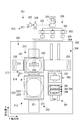
図10に示すように、液滴吐出装置201は、機台202と、機台202上の全域に広く載置され、機能液滴吐出ヘッド252を有する描画装置203と、機台202上で描画装置203に添設させたヘッド保守装置204と、機能液滴吐出ヘッド252に機能液を供給する機能液供給装置205と、各装置を制御する図外の制御装置206と、を備えている。そして、液滴吐出装置201では、制御装置206による制御に基づいて、描画装置203が、図外のワーク移載ロボットから導入されたワークに対して、描画処理を行うと共に、ヘッド保守装置204が機能液滴吐出ヘッド252に対して適宜保守処理(メンテナンス)を行うようになっている。
As shown in FIG. 10, the
描画装置203は、主走査方向(X軸方向)に延在するX軸テーブル211と、X軸テーブル211に直交するY軸テーブル212と、Y軸テーブル212に移動自在に取り付けられたメインキャリッジ213と、メインキャリッジ213に支持され、(複数の)機能液滴吐出ヘッド252を搭載したヘッドユニット214と、を備えている。
The
X軸テーブル211は、X軸方向の駆動系を構成するX軸モータ(図示省略)駆動のX軸スライダ221に、ワークWをセットするセットテーブル222を移動自在に搭載して構成されている。セットテーブル222は、ワークWを吸着セットする吸着テーブル223と、吸着テーブル223にセットしたワークWの位置をθ軸方向に補正するθテーブル224と、を有している。なお、機台202には、X軸方向を移動するセットテーブル222の移動位置を把握するためのX軸リニアセンサ225が設けられている。
The X-axis table 211 is configured by movably mounting a set table 222 for setting a workpiece W on an
Y軸テーブル212は、X軸テーブル211と略同様に構成されており、Y軸方向の駆動系を構成するY軸モータ(図示省略)駆動のY軸スライダ231を有し、メインキャリッジ213をY軸方向に移動自在に搭載している。また、Y軸テーブル212に並設するように、Y軸方向を移動するヘッドユニット214の移動位置を把握するためのY軸リニアセンサ232が設けられている。なお、Y軸テーブル212は、機台202上に立設した左右の支柱235を介して、機台202上に配設されたX軸テーブル211およびヘッド保守装置204を跨ぐように配設されており、X軸テーブル211およびY軸テーブル212が交わるエリアがワークWの描画を行う描画エリア、Y軸テーブル212およびヘッド保守装置204が交わるエリアが機能液滴吐出ヘッド252に対する保守動作を行う保守エリアとなっている。
The Y-axis table 212 is configured in substantially the same manner as the X-axis table 211, has a Y-axis motor (not shown) driving Y-
メインキャリッジ213は、ヘッドユニット214を支持するキャリッジ本体241と、キャリッジ本体241を介して、ヘッドユニット214のθ方向に対する位置補正を行うためのθ回転機構242と、θ回転機構242を介して、キャリッジ本体241(ヘッドユニット214)をY軸テーブル212に支持させる略I字状の吊設部材(図示省略)と、で構成されている。
The
ヘッドユニット214は、ヘッドプレート251にヘッド保持部材(図示省略)を介して機能液滴吐出ヘッド252を搭載させて構成されている。機能液滴吐出ヘッド252は、上記したインクジェットヘッド41と同様の方式で構成されているため、ここでの説明は省述する。
The
描画処理時における描画装置203の一連の動作について説明すると、先ず、θ回転機構242を介してヘッドユニット214の位置補正が行われると共に、θテーブル224を介してセットテーブル222にセットされたワークWの位置補正が行われる。次に、X軸テーブル211が駆動して、ワークWを主走査(X軸)方向に往復動させる。ワークWの往動と同期して、複数の機能液滴吐出ヘッド252が駆動し、ワークWに対する機能液滴の選択的な吐出動作が行われる。ワークWの往動が終了すると、Y軸テーブル212が駆動して、ヘッドユニット214を副走査(Y軸)方向に移動させる。そして、ワークWの主走査方向へ復動と機能液滴吐出ヘッド252の駆動が再び行われる。このように、描画処理では、ワークWのX軸方向への移動とこれに同期した機能液滴吐出ヘッド252の吐出駆動(主走査)と、ヘッドユニット214のY軸方向への移動(副走査)と、を交互に繰り返すことにより、ワークWに対して所定の描画パターンを描画してゆく。
A series of operations of the
ヘッド保守装置204は、機台202上に載置された移動テーブル261と、フラッシングユニット262と、吸引ユニット263と、ワイピングユニット264と、を備えている。移動テーブル261は、X軸方向に移動可能に構成されている。吸引ユニット263およびワイピングユニット264は、X軸方向に並んで移動テーブル261上に設置されており、機能液滴吐出ヘッド252の保守時には、移動テーブル261が駆動され、吸引ユニット263およびワイピングユニット264が適宜保守エリアに臨む構成となっている。
The
フラッシングユニット262は、(1枚の)ワークWに対する一連の描画処理中において、ヘッドユニット214の全機能液滴吐出ヘッド252から捨て吐出(フラッシング)される機能液と、描画処理中にワークWからはみ出した機能液を受けるためのものであり、吸着テーブル223のY軸方向に平行な一対の辺(周縁)に沿うように設けられた一対の描画フラッシングボックス271を有している。したがって、吸着テーブル223を介してワークWをX軸方向に往復動させると、(1回の主走査により、ヘッドユニット214がワークWに臨む直前およびヘッドユニット214がワークWから離間した直後のいずれの場合においても)ヘッドユニット214の全機能液滴吐出ヘッド252を順次描画フラッシングボックス271に臨ませることができ、ワークWに対する描画動作の直前・直後に行われる捨て吐出の機能液を適切に受けることができる。
The
吸引ユニット263は、上述の吸引手段131に相当するものであり、機能液滴吐出ヘッド252のノズル面に密着させるキャップ281と、キャップ281を介して機能液滴吐出ヘッド252を吸引可能な単一の吸引ポンプ等を備えている。
The
ワイピングユニット264は、洗浄液を噴霧したワイピングシート291で機能液滴吐出ヘッド252のノズル面に付着した汚れを払拭するためのものであり、ロール状に巻回したワイピングシート291を繰り出しながら巻き取ってゆく巻取りユニット292と、繰り出したワイピングシート291に洗浄液を散布する洗浄液供給ユニット293と、洗浄液が散布されたワイピングシート291でノズル面を拭取る拭取りユニット294と、を備えている。
The
機能液供給装置205は、R・G・B3色の機能液に対応する3個の機能液タンク301と、3個の機能液タンク301を収容するタンクホルダ302と、機能液タンク301の機能液を機能液滴吐出ヘッド252に加圧送液する加圧手段303と、3個の機能液タンク301と機能液滴吐出ヘッド252とを配管接続する複数本(本実施形態では3本)の給液チューブ304と、インクジェットプリンタ1のものと同様に構成され、各給液チューブ304に介設された圧力調整弁305と、を備えている。
The functional
機能液供給装置205は、上述のインク供給手段と略同様に構成されており、機能液タンク301はカートリッジ形式のものが採用されている。タンクホルダ302には、各機能液タンク301を収容する機能液収容部(図示省略)が設けられ、各機能液収容部には、機能液タンク301とエアー配管323とを接続する接続アダプタ(図示省略)が配設されている。また、加圧手段303は、接続アダプタを介して各機能液タンク301にエアーを供給するエアー供給機構321を有し、エアー供給機構321を構成する単一の加圧ポンプ322を駆動すると、エアー配管323を介して各機能液タンク301にエアーが供給される。この場合も、エアー配管323には、ソレノイド付きレギュレータ324および圧力センサ325が介設されており、エアー配管323内が所定の作動圧力に維持されるように構成されている。
The functional
制御装置206は、パソコン等で構成され、データ入力、各種設定を行うための入力手段(キーボード等)や、入力データ・各種設定状態等を視認するためのディスプレイ等を備えている(いずれも図示省略)。 The control device 206 is configured by a personal computer or the like, and includes an input means (keyboard or the like) for performing data input and various settings, a display for visually confirming input data and various setting states, and the like (both illustrated). (Omitted).
図11を参照しながら液滴吐出装置201の主制御系について説明する。液滴吐出装置201は、描画装置203を有する描画部331と、ヘッド保守装置204を有するヘッド保守部332と、機能液供給装置205を有する機能液供給部333と、描画装置203、ヘッド保守装置204および機能液供給装置205の各種センサを有し、各種検出を行う検出部334と、各部を駆動する各種ドライバ(描画装置203を駆動するための描画ドライバ341、ヘッド保守装置204を駆動するためのヘッド保守ドライバ342、機能液供給装置を駆動するための機能液供給ドライバ343等)を有する駆動部335と、各部に接続され、液滴吐出装置201全体の制御を行う制御部336(制御装置206)と、を備えている。
The main control system of the
制御部336は、描画装置203およびヘッド保守装置204等を接続するためのインタフェース351、および描画装置203、ヘッド保守装置204、機能液供給装置205からの各種データ等を記憶すると共に、各種データを処理するためのプログラム等を記憶するハードディスク352が備えられている以外は、上述のインクジェットプリンタ1の制御部336と略同様に構成され、RAM353、ROM354、CPU355、タイマー356、内部バス357と、を備えている。
The
本実施形態の液滴吐出装置201も、上述のインクジェットプリンタ1と同様の制御が行われている。すなわち、制御部336が加圧ポンプ322の駆動制御を行うことにより、機能液タンク301から供給される機能液の供給圧力が、予め設定した作動圧力内に調整されると共に、ワークWに描画動作中の機能液滴吐出ヘッド252のヘッド内流路に圧力変動を生じさせず、且つ機能液滴吐出ヘッド252がワークWに描画動作中のときには、機能液の加圧供給が行われないようになっている。そして、描画処理を中断して機能液の加圧供給を行う場合には、X軸テーブル211またはY軸テーブル212を駆動させることにより、ヘッドユニット214をフラッシングユニット262または保守エリアに臨ませて、ヘッド保守装置204でメンテナンスするようになっており、加圧供給が終了するまでの待ち時間を利用して、機能液滴吐出ヘッド252をメンテナンスできるようになっている。したがって、液滴吐出装置201は、描画パターンを極めて高精度に描画することが可能である。
The
次に、本実施形態の液滴吐出装置201を用いて製造される電気光学装置(フラットパネルディスプレイ)として、カラーフィルタ、液晶表示装置、有機EL装置、プラズマディスプレイ(PDP装置)、電子放出装置(FED装置、SED装置)、更にこれら表示装置に形成されてなるアクティブマトリクス基板等を例に、これらの構造およびその製造方法について説明する。なお、アクティブマトリクス基板とは、薄膜トランジスタ、及び薄膜トランジスタに電気的に接続するソース線、データ線が形成された基板を言う。
Next, as an electro-optical device (flat panel display) manufactured using the
先ず、液晶表示装置や有機EL装置等に組み込まれるカラーフィルタの製造方法について説明する。図12は、カラーフィルタの製造工程を示すフローチャート、図13は、製造工程順に示した本実施形態のカラーフィルタ600(フィルタ基体600A)の模式断面図である。
まず、ブラックマトリクス形成工程(S101)では、図13(a)に示すように、基板(W)601上にブラックマトリクス602を形成する。ブラックマトリクス602は、金属クロム、金属クロムと酸化クロムの積層体、または樹脂ブラック等により形成される。金属薄膜からなるブラックマトリクス602を形成するには、スパッタ法や蒸着法等を用いることができる。また、樹脂薄膜からなるブラックマトリクス602を形成する場合には、グラビア印刷法、フォトレジスト法、熱転写法等を用いることができる。
First, a method for manufacturing a color filter incorporated in a liquid crystal display device, an organic EL device or the like will be described. FIG. 12 is a flowchart showing the manufacturing process of the color filter, and FIG. 13 is a schematic cross-sectional view of the color filter 600 (filter
First, in the black matrix forming step (S101), a
続いて、バンク形成工程(S102)において、ブラックマトリクス602上に重畳する状態でバンク603を形成する。即ち、まず図13(b)に示すように、基板601及びブラックマトリクス602を覆うようにネガ型の透明な感光性樹脂からなるレジスト層604を形成する。そして、その上面をマトリクスパターン形状に形成されたマスクフィルム605で被覆した状態で露光処理を行う。
さらに、図13(c)に示すように、レジスト層604の未露光部分をエッチング処理することによりレジスト層604をパターニングして、バンク603を形成する。なお、樹脂ブラックによりブラックマトリクスを形成する場合は、ブラックマトリクスとバンクとを兼用することが可能となる。
このバンク603とその下のブラックマトリクス602は、各画素領域607aを区画する区画壁部607bとなり、後の着色層形成工程において機能液滴吐出ヘッド252により着色層(成膜部)608R、608G、608Bを形成する際に機能液滴の着弾領域を規定する。
Subsequently, in a bank formation step (S102), a
Further, as shown in FIG. 13C, the resist
The
以上のブラックマトリクス形成工程及びバンク形成工程を経ることにより、上記フィルタ基体600Aが得られる。
なお、本実施形態においては、バンク603の材料として、塗膜表面が疎液(疎水)性となる樹脂材料を用いている。そして、基板(ガラス基板)601の表面が親液(親水)性であるので、後述する着色層形成工程においてバンク603(区画壁部607b)に囲まれた各画素領域607a内への液滴の着弾位置精度が向上する。
The
In the present embodiment, as the material of the
次に、着色層形成工程(S103)では、図13(d)に示すように、機能液滴吐出ヘッド252によって機能液滴を吐出して区画壁部607bで囲まれた各画素領域607a内に着弾させる。この場合、機能液滴吐出ヘッド252を用いて、R・G・Bの3色の機能液(フィルタ材料)を導入して、機能液滴の吐出を行う。なお、R・G・Bの3色の配列パターンとしては、ストライプ配列、モザイク配列およびデルタ配列等がある。
Next, in the colored layer forming step (S103), as shown in FIG. 13D, functional droplets are ejected by the functional
その後、乾燥処理(加熱等の処理)を経て機能液を定着させ、3色の着色層608R、608G、608Bを形成する。着色層608R、608G、608Bを形成したならば、保護膜形成工程(S104)に移り、図13(e)に示すように、基板601、区画壁部607b、および着色層608R、608G、608Bの上面を覆うように保護膜609を形成する。
即ち、基板601の着色層608R、608G、608Bが形成されている面全体に保護膜用塗布液が吐出された後、乾燥処理を経て保護膜609が形成される。
そして、保護膜609を形成した後、カラーフィルタ600は、次工程の透明電極となるITO(Indium Tin Oxide)などの膜付け工程に移行する。
Thereafter, the functional liquid is fixed through a drying process (a process such as heating) to form three
That is, after the protective film coating liquid is discharged over the entire surface of the
Then, after forming the
図14は、上記のカラーフィルタ600を用いた液晶表示装置の一例としてのパッシブマトリックス型液晶装置(液晶装置)の概略構成を示す要部断面図である。この液晶装置620に、液晶駆動用IC、バックライト、支持体などの付帯要素を装着することによって、最終製品としての透過型液晶表示装置が得られる。なお、カラーフィルタ600は図13に示したものと同一であるので、対応する部位には同一の符号を付し、その説明は省略する。
FIG. 14 is a cross-sectional view of a main part showing a schematic configuration of a passive matrix liquid crystal device (liquid crystal device) as an example of a liquid crystal display device using the
この液晶装置620は、カラーフィルタ600、ガラス基板等からなる対向基板621、及び、これらの間に挟持されたSTN(Super Twisted Nematic)液晶組成物からなる液晶層622により概略構成されており、カラーフィルタ600を図中上側(観測者側)に配置している。
なお、図示していないが、対向基板621およびカラーフィルタ600の外面(液晶層622側とは反対側の面)には偏光板がそれぞれ配設され、また対向基板621側に位置する偏光板の外側には、バックライトが配設されている。
The
Although not shown, polarizing plates are disposed on the outer surfaces of the
カラーフィルタ600の保護膜609上(液晶層側)には、図14において左右方向に長尺な短冊状の第1電極623が所定の間隔で複数形成されており、この第1電極623のカラーフィルタ600側とは反対側の面を覆うように第1配向膜624が形成されている。
一方、対向基板621におけるカラーフィルタ600と対向する面には、カラーフィルタ600の第1電極623と直交する方向に長尺な短冊状の第2電極626が所定の間隔で複数形成され、この第2電極626の液晶層622側の面を覆うように第2配向膜627が形成されている。これらの第1電極623および第2電極626は、ITOなどの透明導電材料により形成されている。
On the
On the other hand, a plurality of strip-shaped
液晶層622内に設けられたスペーサ628は、液晶層622の厚さ(セルギャップ)を一定に保持するための部材である。また、シール材629は液晶層622内の液晶組成物が外部へ漏出するのを防止するための部材である。なお、第1電極623の一端部は引き回し配線623aとしてシール材629の外側まで延在している。
そして、第1電極623と第2電極626とが交差する部分が画素であり、この画素となる部分に、カラーフィルタ600の着色層608R、608G、608Bが位置するように構成されている。
The
A portion where the
通常の製造工程では、カラーフィルタ600に、第1電極623のパターニングおよび第1配向膜624の塗布を行ってカラーフィルタ600側の部分を作成すると共に、これとは別に対向基板621に、第2電極626のパターニングおよび第2配向膜627の塗布を行って対向基板621側の部分を作成する。その後、対向基板621側の部分にスペーサ628およびシール材629を作り込み、この状態でカラーフィルタ600側の部分を貼り合わせる。次いで、シール材629の注入口から液晶層622を構成する液晶を注入し、注入口を閉止する。その後、両偏光板およびバックライトを積層する。
In a normal manufacturing process, patterning of the
実施形態の液滴吐出装置201は、例えば上記のセルギャップを構成するスペーサ材料(機能液)を塗布すると共に、対向基板621側の部分にカラーフィルタ600側の部分を貼り合わせる前に、シール材629で囲んだ領域に液晶(機能液)を均一に塗布することが可能である。また、上記のシール材629の印刷を、機能液滴吐出ヘッド252で行うことも可能である。さらに、第1・第2両配向膜624,627の塗布を機能液滴吐出ヘッド252で行うことも可能である。
The
図15は、本実施形態において製造したカラーフィルタ600を用いた液晶装置の第2の例の概略構成を示す要部断面図である。
この液晶装置630が上記液晶装置620と大きく異なる点は、カラーフィルタ600を図中下側(観測者側とは反対側)に配置した点である。
この液晶装置630は、カラーフィルタ600とガラス基板等からなる対向基板631との間にSTN液晶からなる液晶層632が挟持されて概略構成されている。なお、図示していないが、対向基板631およびカラーフィルタ600の外面には偏光板等がそれぞれ配設されている。
FIG. 15 is a cross-sectional view of a principal part showing a schematic configuration of a second example of a liquid crystal device using the
The
The
カラーフィルタ600の保護膜609上(液晶層632側)には、図中奥行き方向に長尺な短冊状の第1電極633が所定の間隔で複数形成されており、この第1電極633の液晶層632側の面を覆うように第1配向膜634が形成されている。
対向基板631のカラーフィルタ600と対向する面上には、カラーフィルタ600側の第1電極633と直交する方向に延在する複数の短冊状の第2電極636が所定の間隔で形成され、この第2電極636の液晶層632側の面を覆うように第2配向膜637が形成されている。
On the
A plurality of strip-shaped
液晶層632には、この液晶層632の厚さを一定に保持するためのスペーサ638と、液晶層632内の液晶組成物が外部へ漏出するのを防止するためのシール材639が設けられている。
そして、上記した液晶装置620と同様に、第1電極633と第2電極636との交差する部分が画素であり、この画素となる部位に、カラーフィルタ600の着色層608R、608G、608Bが位置するように構成されている。
The
Similarly to the
図16は、本発明を適用したカラーフィルタ600を用いて液晶装置を構成した第3の例を示したもので、透過型のTFT(Thin Film Transistor)型液晶装置の概略構成を示す分解斜視図である。
この液晶装置650は、カラーフィルタ600を図中上側(観測者側)に配置したものである。
FIG. 16 shows a third example in which a liquid crystal device is configured using a
In the
この液晶装置650は、カラーフィルタ600と、これに対向するように配置された対向基板651と、これらの間に挟持された図示しない液晶層と、カラーフィルタ600の上面側(観測者側)に配置された偏光板655と、対向基板651の下面側に配設された偏光板(図示せず)とにより概略構成されている。
カラーフィルタ600の保護膜609の表面(対向基板651側の面)には液晶駆動用の電極656が形成されている。この電極656は、ITO等の透明導電材料からなり、後述の画素電極660が形成される領域全体を覆う全面電極となっている。また、この電極656の画素電極660とは反対側の面を覆った状態で配向膜657が設けられている。
The
A liquid
対向基板651のカラーフィルタ600と対向する面には絶縁層658が形成されており、この絶縁層658上には、走査線661及び信号線662が互いに直交する状態で形成されている。そして、これらの走査線661と信号線662とに囲まれた領域内には画素電極660が形成されている。なお、実際の液晶装置では、画素電極660上に配向膜が設けられるが、図示を省略している。
An insulating
また、画素電極660の切欠部と走査線661と信号線662とに囲まれた部分には、ソース電極、ドレイン電極、半導体、およびゲート電極とを具備する薄膜トランジスタ663が組み込まれて構成されている。そして、走査線661と信号線662に対する信号の印加によって薄膜トランジスタ663をオン・オフして画素電極660への通電制御を行うことができるように構成されている。
In addition, a
なお、上記の各例の液晶装置620,630,650は、透過型の構成としたが、反射層あるいは半透過反射層を設けて、反射型の液晶装置あるいは半透過反射型の液晶装置とすることもできる。
The
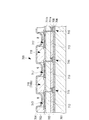
次に、図17は、有機EL装置の表示領域(以下、単に表示装置700と称する)の要部断面図である。 Next, FIG. 17 is a cross-sectional view of an essential part of a display region (hereinafter simply referred to as a display device 700) of the organic EL device.
この表示装置700は、基板(W)701上に、回路素子部702、発光素子部703及び陰極704が積層された状態で概略構成されている。
この表示装置700においては、発光素子部703から基板701側に発した光が、回路素子部702及び基板701を透過して観測者側に出射されるとともに、発光素子部703から基板701の反対側に発した光が陰極704により反射された後、回路素子部702及び基板701を透過して観測者側に出射されるようになっている。
The
In this
回路素子部702と基板701との間にはシリコン酸化膜からなる下地保護膜706が形成され、この下地保護膜706上(発光素子部703側)に多結晶シリコンからなる島状の半導体膜707が形成されている。この半導体膜707の左右の領域には、ソース領域707a及びドレイン領域707bが高濃度陽イオン打ち込みによりそれぞれ形成されている。そして陽イオンが打ち込まれない中央部がチャネル領域707cとなっている。
A base
また、回路素子部702には、下地保護膜706及び半導体膜707を覆う透明なゲート絶縁膜708が形成され、このゲート絶縁膜708上の半導体膜707のチャネル領域707cに対応する位置には、例えばAl、Mo、Ta、Ti、W等から構成されるゲート電極709が形成されている。このゲート電極709及びゲート絶縁膜708上には、透明な第1層間絶縁膜711aと第2層間絶縁膜711bが形成されている。また、第1、第2層間絶縁膜711a、711bを貫通して、半導体膜707のソース領域707a、ドレイン領域707bにそれぞれ連通するコンタクトホール712a,712bが形成されている。
In the
そして、第2層間絶縁膜711b上には、ITO等からなる透明な画素電極713が所定の形状にパターニングされて形成され、この画素電極713は、コンタクトホール712aを通じてソース領域707aに接続されている。
また、第1層間絶縁膜711a上には電源線714が配設されており、この電源線714は、コンタクトホール712bを通じてドレイン領域707bに接続されている。
A
A
このように、回路素子部702には、各画素電極713に接続された駆動用の薄膜トランジスタ715がそれぞれ形成されている。
Thus, the driving
上記発光素子部703は、複数の画素電極713上の各々に積層された機能層717と、各画素電極713及び機能層717の間に備えられて各機能層717を区画するバンク部718とにより概略構成されている。
これら画素電極713、機能層717、及び、機能層717上に配設された陰極704によって発光素子が構成されている。なお、画素電極713は、平面視略矩形状にパターニングされて形成されており、各画素電極713の間にバンク部718が形成されている。
The light emitting
The
バンク部718は、例えばSiO、SiO2、TiO2等の無機材料により形成される無機物バンク層718a(第1バンク層)と、この無機物バンク層718a上に積層され、アクリル樹脂、ポリイミド樹脂等の耐熱性、耐溶媒性に優れたレジストにより形成される断面台形状の有機物バンク層718b(第2バンク層)とにより構成されている。このバンク部718の一部は、画素電極713の周縁部上に乗上げた状態で形成されている。
そして、各バンク部718の間には、画素電極713に対して上方に向けて次第に拡開した開口部719が形成されている。
Between each
上記機能層717は、開口部719内において画素電極713上に積層状態で形成された正孔注入/輸送層717aと、この正孔注入/輸送層717a上に形成された発光層717bとにより構成されている。なお、この発光層717bに隣接してその他の機能を有する他の機能層を更に形成しても良い。例えば、電子輸送層を形成する事も可能である。
正孔注入/輸送層717aは、画素電極713側から正孔を輸送して発光層717bに注入する機能を有する。この正孔注入/輸送層717aは、正孔注入/輸送層形成材料を含む第1組成物(機能液)を吐出することで形成される。正孔注入/輸送層形成材料としては、公知の材料を用いる。
The
The hole injection /
発光層717bは、赤色(R)、緑色(G)、又は青色(B)の何れかに発光するもので、発光層形成材料(発光材料)を含む第2組成物(機能液)を吐出することで形成される。第2組成物の溶媒(非極性溶媒)としては、正孔注入/輸送層717aに対して不溶な公知の材料を用いることが好ましく、このような非極性溶媒を発光層717bの第2組成物に用いることにより、正孔注入/輸送層717aを再溶解させることなく発光層717bを形成することができる。
The
そして、発光層717bでは、正孔注入/輸送層717aから注入された正孔と、陰極704から注入される電子が発光層で再結合して発光するように構成されている。
The
陰極704は、発光素子部703の全面を覆う状態で形成されており、画素電極713と対になって機能層717に電流を流す役割を果たす。なお、この陰極704の上部には図示しない封止部材が配置される。
The
次に、上記の表示装置700の製造工程を図18〜図26を参照して説明する。
この表示装置700は、図18に示すように、バンク部形成工程(S111)、表面処理工程(S112)、正孔注入/輸送層形成工程(S113)、発光層形成工程(S114)、及び対向電極形成工程(S115)を経て製造される。なお、製造工程は例示するものに限られるものではなく必要に応じてその他の工程が除かれる場合、また追加される場合もある。
Next, a manufacturing process of the
As shown in FIG. 18, the
まず、バンク部形成工程(S111)では、図19に示すように、第2層間絶縁膜711b上に無機物バンク層718aを形成する。この無機物バンク層718aは、形成位置に無機物膜を形成した後、この無機物膜をフォトリソグラフィ技術等によりパターニングすることにより形成される。このとき、無機物バンク層718aの一部は画素電極713の周縁部と重なるように形成される。
無機物バンク層718aを形成したならば、図20に示すように、無機物バンク層718a上に有機物バンク層718bを形成する。この有機物バンク層718bも無機物バンク層718aと同様にフォトリソグラフィ技術等によりパターニングして形成される。
このようにしてバンク部718が形成される。また、これに伴い、各バンク部718間には、画素電極713に対して上方に開口した開口部719が形成される。この開口部719は、画素領域を規定する。
First, in the bank part forming step (S111), as shown in FIG. 19, an
When the
In this way, the
表面処理工程(S112)では、親液化処理及び撥液化処理が行われる。親液化処理を施す領域は、無機物バンク層718aの第1積層部718aa及び画素電極713の電極面713aであり、これらの領域は、例えば酸素を処理ガスとするプラズマ処理によって親液性に表面処理される。このプラズマ処理は、画素電極713であるITOの洗浄等も兼ねている。
また、撥液化処理は、有機物バンク層718bの壁面718s及び有機物バンク層718bの上面718tに施され、例えば4フッ化メタンを処理ガスとするプラズマ処理によって表面がフッ化処理(撥液性に処理)される。
この表面処理工程を行うことにより、機能液滴吐出ヘッド252を用いて機能層717を形成する際に、機能液滴を画素領域に、より確実に着弾させることができ、また、画素領域に着弾した機能液滴が開口部719から溢れ出るのを防止することが可能となる。
In the surface treatment step (S112), a lyophilic process and a lyophobic process are performed. The regions to be subjected to the lyophilic treatment are the first stacked portion 718aa of the
In addition, the lyophobic treatment is performed on the
By performing this surface treatment process, when forming the
そして、以上の工程を経ることにより、表示装置基体700Aが得られる。この表示装置基体700Aは、図10に示した液滴吐出装置201のセットテーブル222に載置され、以下の正孔注入/輸送層形成工程(S113)及び発光層形成工程(S114)が行われる。
The display device base 700A is obtained through the above steps. The display device substrate 700A is placed on the set table 222 of the
図21に示すように、正孔注入/輸送層形成工程(S113)では、機能液滴吐出ヘッド252から正孔注入/輸送層形成材料を含む第1組成物を画素領域である各開口部719内に吐出する。その後、図22に示すように、乾燥処理及び熱処理を行い、第1組成物に含まれる極性溶媒を蒸発させ、画素電極(電極面713a)713上に正孔注入/輸送層717aを形成する。
As shown in FIG. 21, in the hole injection / transport layer forming step (S113), the first composition containing the hole injection / transport layer forming material is transferred from the functional liquid
次に発光層形成工程(S114)について説明する。この発光層形成工程では、上述したように、正孔注入/輸送層717aの再溶解を防止するために、発光層形成の際に用いる第2組成物の溶媒として、正孔注入/輸送層717aに対して不溶な非極性溶媒を用いる。
しかしその一方で、正孔注入/輸送層717aは、非極性溶媒に対する親和性が低いため、非極性溶媒を含む第2組成物を正孔注入/輸送層717a上に吐出しても、正孔注入/輸送層717aと発光層717bとを密着させることができなくなるか、あるいは発光層717bを均一に塗布できない虞がある。
そこで、非極性溶媒ならびに発光層形成材料に対する正孔注入/輸送層717aの表面の親和性を高めるために、発光層形成の前に表面処理(表面改質処理)を行うことが好ましい。この表面処理は、発光層形成の際に用いる第2組成物の非極性溶媒と同一溶媒またはこれに類する溶媒である表面改質材を、正孔注入/輸送層717a上に塗布し、これを乾燥させることにより行う。
このような処理を施すことで、正孔注入/輸送層717aの表面が非極性溶媒になじみやすくなり、この後の工程で、発光層形成材料を含む第2組成物を正孔注入/輸送層717aに均一に塗布することができる。
Next, the light emitting layer forming step (S114) will be described. In this light emitting layer forming step, as described above, in order to prevent re-dissolution of the hole injection /
However, since the hole injection /
Therefore, in order to increase the surface affinity of the hole injection /
By performing such a treatment, the surface of the hole injection /
そして次に、図23に示すように、各色のうちの何れか(図23の例では青色(B))に対応する発光層形成材料を含有する第2組成物を機能液滴として画素領域(開口部719)内に所定量打ち込む。画素領域内に打ち込まれた第2組成物は、正孔注入/輸送層717a上に広がって開口部719内に満たされる。なお、万一、第2組成物が画素領域から外れてバンク部718の上面718t上に着弾した場合でも、この上面718tは、上述したように撥液処理が施されているので、第2組成物が開口部719内に転がり込み易くなっている。
Then, as shown in FIG. 23, the second composition containing the light-emitting layer forming material corresponding to one of the colors (blue (B) in the example of FIG. 23) is used as a functional droplet as a pixel region ( A predetermined amount is driven into the opening 719). The second composition driven into the pixel region spreads on the hole injection /
その後、乾燥工程等を行う事により、吐出後の第2組成物を乾燥処理し、第2組成物に含まれる非極性溶媒を蒸発させ、図24に示すように、正孔注入/輸送層717a上に発光層717bが形成される。この図の場合、青色(B)に対応する発光層717bが形成されている。
Thereafter, by performing a drying process or the like, the discharged second composition is dried, the nonpolar solvent contained in the second composition is evaporated, and as shown in FIG. 24, the hole injection /
同様に、機能液滴吐出ヘッド252を用い、図25に示すように、上記した青色(B)に対応する発光層717bの場合と同様の工程を順次行い、他の色(赤色(R)及び緑色(G))に対応する発光層717bを形成する。なお、発光層717bの形成順序は、例示した順序に限られるものではなく、どのような順番で形成しても良い。例えば、発光層形成材料に応じて形成する順番を決める事も可能である。また、R・G・Bの3色の配列パターンとしては、ストライブ配列、モザイク配列およびデルタ配列等がある。
Similarly, using the functional liquid
以上のようにして、画素電極713上に機能層717、即ち、正孔注入/輸送層717a及び発光層717bが形成される。そして、対向電極形成工程(S115)に移行する。
As described above, the
対向電極形成工程(S115)では、図26に示すように、発光層717b及び有機物バンク層718bの全面に陰極704(対向電極)を、例えば蒸着法、スパッタ法、CVD法等によって形成する。この陰極704は、本実施形態においては、例えば、カルシウム層とアルミニウム層とが積層されて構成されている。
この陰極704の上部には、電極としてのAl膜、Ag膜や、その酸化防止のためのSiO2、SiN等の保護層が適宜設けられる。
In the counter electrode forming step (S115), as shown in FIG. 26, a cathode 704 (counter electrode) is formed on the entire surface of the
On top of the
このようにして陰極704を形成した後、この陰極704の上部を封止部材により封止する封止処理や配線処理等のその他処理等を施すことにより、表示装置700が得られる。
After forming the
次に、図27は、プラズマ型表示装置(PDP装置:以下、単に表示装置800と称する)の要部分解斜視図である。なお、同図では表示装置800を、その一部を切り欠いた状態で示してある。
この表示装置800は、互いに対向して配置された第1基板801、第2基板802、及びこれらの間に形成される放電表示部803を含んで概略構成される。放電表示部803は、複数の放電室805により構成されている。これらの複数の放電室805のうち、赤色放電室805R、緑色放電室805G、青色放電室805Bの3つの放電室805が組になって1つの画素を構成するように配置されている。
Next, FIG. 27 is an exploded perspective view of a main part of a plasma display device (PDP device: hereinafter simply referred to as a display device 800). In the figure, the
The
第1基板801の上面には所定の間隔で縞状にアドレス電極806が形成され、このアドレス電極806と第1基板801の上面とを覆うように誘電体層807が形成されている。誘電体層807上には、各アドレス電極806の間に位置し、且つ各アドレス電極806に沿うように隔壁808が立設されている。この隔壁808は、図示するようにアドレス電極806の幅方向両側に延在するものと、アドレス電極806と直交する方向に延設された図示しないものを含む。
そして、この隔壁808によって仕切られた領域が放電室805となっている。
A region partitioned by the
放電室805内には蛍光体809が配置されている。蛍光体809は、赤(R)、緑(G)、青(B)の何れかの色の蛍光を発光するもので、赤色放電室805Rの底部には赤色蛍光体809Rが、緑色放電室805Gの底部には緑色蛍光体809Gが、青色放電室805Bの底部には青色蛍光体809Bが各々配置されている。
A
第2基板802の図中下側の面には、上記アドレス電極806と直交する方向に複数の表示電極811が所定の間隔で縞状に形成されている。そして、これらを覆うように誘電体層812、及びMgOなどからなる保護膜813が形成されている。
第1基板801と第2基板802とは、アドレス電極806と表示電極811が互いに直交する状態で対向させて貼り合わされている。なお、上記アドレス電極806と表示電極811は図示しない交流電源に接続されている。
そして、各電極806,811に通電することにより、放電表示部803において蛍光体809が励起発光し、カラー表示が可能となる。
On the lower surface of the
The
When the
本実施形態においては、上記アドレス電極806、表示電極811、及び蛍光体809を、図10に示した液滴吐出装置201を用いて形成することができる。以下、第1基板801におけるアドレス電極806の形成工程を例示する。
この場合、第1基板801を液滴吐出装置201のセットテーブル222に載置された状態で以下の工程が行われる。
まず、機能液滴吐出ヘッド252により、導電膜配線形成用材料を含有する液体材料(機能液)を機能液滴としてアドレス電極形成領域に着弾させる。この液体材料は、導電膜配線形成用材料として、金属等の導電性微粒子を分散媒に分散したものである。この導電性微粒子としては、金、銀、銅、パラジウム、又はニッケル等を含有する金属微粒子や、導電性ポリマー等が用いられる。
In the present embodiment, the
In this case, the following steps are performed with the
First, a liquid material (functional liquid) containing a conductive film wiring forming material is landed on the address electrode formation region as a functional liquid droplet by the functional liquid
補充対象となる全てのアドレス電極形成領域について液体材料の補充が終了したならば、吐出後の液体材料を乾燥処理し、液体材料に含まれる分散媒を蒸発させることによりアドレス電極806が形成される。
When the replenishment of the liquid material is completed for all the address electrode formation regions to be replenished, the
ところで、上記においてはアドレス電極806の形成を例示したが、上記表示電極811及び蛍光体809についても上記各工程を経ることにより形成することができる。
表示電極811の形成の場合、アドレス電極806の場合と同様に、導電膜配線形成用材料を含有する液体材料(機能液)を機能液滴として表示電極形成領域に着弾させる。
また、蛍光体809の形成の場合には、各色(R,G,B)に対応する蛍光材料を含んだ液体材料(機能液)を機能液滴吐出ヘッド252から液滴として吐出し、対応する色の放電室805内に着弾させる。
By the way, although the formation of the
In the case of forming the
Further, in the case of forming the
次に、図28は、電子放出装置(FED装置あるいはSED装置ともいう:以下、単に表示装置900と称する)の要部断面図である。なお、同図では表示装置900を、その一部を断面として示してある。
この表示装置900は、互いに対向して配置された第1基板901、第2基板902、及びこれらの間に形成される電界放出表示部903を含んで概略構成される。電界放出表示部903は、マトリクス状に配置した複数の電子放出部905により構成されている。
Next, FIG. 28 is a cross-sectional view of an essential part of an electron emission device (also referred to as an FED device or an SED device: hereinafter simply referred to as a display device 900). In the figure, a part of the
The
第1基板901の上面には、カソード電極906を構成する第1素子電極906aおよび第2素子電極906bが相互に直交するように形成されている。また、第1素子電極906aおよび第2素子電極906bで仕切られた部分には、ギャップ908を形成した導電性膜907が形成されている。すなわち、第1素子電極906a、第2素子電極906bおよび導電性膜907により複数の電子放出部905が構成されている。導電性膜907は、例えば酸化パラジウム(PdO)等で構成され、またギャップ908は、導電性膜907を成膜した後、フォーミング等で形成される。
A
第2基板902の下面には、カソード電極906に対峙するアノード電極909が形成されている。アノード電極909の下面には、格子状のバンク部911が形成され、このバンク部911で囲まれた下向きの各開口部912に、電子放出部905に対応するように蛍光体913が配置されている。蛍光体913は、赤(R)、緑(G)、青(B)の何れかの色の蛍光を発光するもので、各開口部912には、赤色蛍光体913R、緑色蛍光体913Gおよび青色蛍光体913Bが、上記した所定のパターンで配置されている。
An
そして、このように構成した第1基板901と第2基板902とは、微小な間隙を存して貼り合わされている。この表示装置900では、導電性膜(ギャップ908)907を介して、陰極である第1素子電極906aまたは第2素子電極906bから飛び出す電子を、陽極であるアノード電極909に形成した蛍光体913に当てて励起発光し、カラー表示が可能となる。
The
この場合も、他の実施形態と同様に、第1素子電極906a、第2素子電極906b、導電性膜907およびアノード電極909を、液滴吐出装置201を用いて形成することができると共に、各色の蛍光体913R,913G,913Bを、液滴吐出装置201を用いて形成することができる。
Also in this case, as in the other embodiments, the
第1素子電極906a、第2素子電極906bおよび導電性膜907は、図29(a)に示す平面形状を有しており、これらを成膜する場合には、図29(b)に示すように、予め第1素子電極906a、第2素子電極906bおよび導電性膜907を作り込む部分を残して、バンク部BBを形成(フォトリソグラフィ法)する。次に、バンク部BBにより構成された溝部分に、第1素子電極906aおよび第2素子電極906bを形成(液滴吐出装置201によるインクジェット法)し、その溶剤を乾燥させて成膜を行った後、導電性膜907を形成(液滴吐出装置201によるインクジェット法)する。そして、導電性膜907を成膜後、バンク部BBを取り除き(アッシング剥離処理)、上記のフォーミング処理に移行する。なお、上記の有機EL装置の場合と同様に、第1基板901および第2基板902に対する親液化処理や、バンク部911,BBに対する撥液化処理を行うことが、好ましい。
The
また、他の電気光学装置としては、金属配線形成、レンズ形成、レジスト形成および光拡散体形成等の装置が考えられる。上記した液滴吐出装置201を各種の電気光学装置(デバイス)の製造に用いることにより、各種の電気光学装置を効率的に製造することが可能である。
As other electro-optical devices, devices such as metal wiring formation, lens formation, resist formation, and light diffuser formation are conceivable. By using the above-described
1 インクジェットプリンタ 23 インク供給手段
25 制御手段 41 インクジェットヘッド
81 インクカートリッジ 112 加圧ポンプ
115 圧力センサ 121 圧力調整弁
167 制御部
DESCRIPTION OF
Claims (9)
描画領域にセットされた描画対象物に対して、前記機能液滴吐出ヘッドを相対的に移動させながら、前記機能液滴吐出ヘッドを駆動することにより前記機能液滴を吐出させて、描画を行う描画動作と、を実行する液滴吐出装置の制御方法において、
前記機能液タンク内の圧力が前記作動圧力の下限圧力以下か否かを検出する圧力検出工程と、
前記機能液タンク内の圧力が前記下限圧力以下のときに、前記機能液滴吐出ヘッドが前記描画動作中であるか否かを確認する描画動作確認工程と、
前記描画動作中でないと確認されたときに、前記機能液タンクを前記作動圧力の上限圧力まで加圧する第1加圧制御工程と、を備えたことを特徴とする液滴吐出装置の制御方法。 Pressure for performing the functional liquid tank while maintaining the operating pressure to cause the ejection of functional liquid droplets of a predetermined amount from pressurizing the functional liquid tank from the functional liquid droplet ejecting heads pressurized supply of the functional liquid to the functional liquid droplet ejecting heads Supply operation,
Drawing is performed by ejecting the functional liquid droplets by driving the functional liquid droplet ejection head while moving the functional liquid droplet ejection head relative to the drawing object set in the drawing area. In a method for controlling a droplet discharge device that performs a drawing operation,
A pressure detection step of detecting whether or not the pressure in the functional liquid tank is equal to or lower than a lower limit pressure of the operating pressure;
A drawing operation confirmation step for confirming whether or not the functional liquid droplet ejection head is performing the drawing operation when the pressure in the functional liquid tank is equal to or lower than the lower limit pressure;
And a first pressurization control step of pressurizing the functional liquid tank to the upper limit pressure of the operating pressure when it is confirmed that the drawing operation is not being performed.
前記描画動作中であると確認され、かつ前記機能液滴吐出ヘッドが前記描画領域に臨んでいることが確認されたときには、前記機能液滴吐出ヘッドが前記描画領域から外れるのを待って、前記描画動作を中断すると共に前記機能液タンクを前記上限圧力まで加圧し、
前記描画動作中であると確認され、前記機能液滴吐出ヘッドが前記描画領域に臨んでいないことが確認されたときには、前記描画動作を中断して前記機能液タンクを前記上限圧力まで加圧する第2加圧制御工程と、
前記第2加圧工程の後に、前記描画動作を再開させる描画再開工程と、をさらに備えたことを特徴とする請求項1に記載の液滴吐出装置の制御方法。 The functional liquid droplet ejection head during the drawing operation discharges the functional liquid droplets to the drawing area located in the drawing movement area while relatively moving in the drawing movement area,
When it is confirmed that the drawing operation is being performed and it is confirmed that the functional liquid droplet ejection head faces the drawing area, the functional liquid droplet ejection head waits for the functional liquid droplet ejection head to move out of the drawing area, Suspending the drawing operation and pressurizing the functional liquid tank to the upper limit pressure,
When it is confirmed that the drawing operation is being performed and it is confirmed that the functional liquid droplet ejection head does not face the drawing region, the drawing operation is interrupted to pressurize the functional liquid tank to the upper limit pressure. 2 pressure control steps;
The method for controlling a droplet discharge device according to claim 1, further comprising a drawing restarting step of restarting the drawing operation after the second pressurizing step.
描画領域にセットされた描画対象物に対して、前記機能液滴吐出ヘッドを相対的に移動させながら、前記機能液滴吐出ヘッドを駆動することにより前記機能液滴を吐出させて、描画を行う描画動作と、を実行する液滴吐出装置において、
前記機能液タンク内の圧力が前記作動圧力の下限圧力以下か否かを検出する圧力検出手段と、
前記機能液タンク内の圧力が前記下限圧力以下のときに、前記機能液滴吐出ヘッドが前記描画動作中であるか否かを確認する描画動作確認手段と、
前記描画動作中でないと確認されたときに、前記機能液タンクを前記作動圧力の上限圧力まで加圧する第1加圧制御手段と、を備えたことを特徴とする液滴吐出装置。 Pressure for performing the functional liquid tank while maintaining the operating pressure to cause the ejection of functional liquid droplets of a predetermined amount from pressurizing the functional liquid tank from the functional liquid droplet ejecting heads pressurized supply of the functional liquid to the functional liquid droplet ejecting heads Supply operation,
Drawing is performed by ejecting the functional liquid droplets by driving the functional liquid droplet ejection head while moving the functional liquid droplet ejection head relative to the drawing object set in the drawing area. In a droplet discharge device that performs a drawing operation,
Pressure detecting means for detecting whether the pressure in the functional liquid tank is equal to or lower than a lower limit pressure of the operating pressure;
Drawing operation confirmation means for confirming whether or not the functional liquid droplet ejection head is performing the drawing operation when the pressure in the functional liquid tank is equal to or lower than the lower limit pressure;
And a first pressurization control unit configured to pressurize the functional liquid tank to an upper limit pressure of the operating pressure when it is confirmed that the drawing operation is not being performed.
前記描画動作中であると確認され、かつ前記機能液滴吐出ヘッドが前記描画領域に臨んでいることが確認されたときには、前記機能液滴吐出ヘッドが前記描画領域から外れるのを待って、前記描画動作を中断すると共に前記機能液タンクを前記上限圧力まで加圧し、
前記描画動作中であると確認され、前記機能液滴吐出ヘッドが前記描画領域に臨んでいないことが確認されたときには、前記描画動作を中断して前記機能液タンクを前記上限圧力まで加圧する第2加圧制御手段と、
前記描画動作を中断して前記機能液タンクを前記上限圧力まで加圧した後に、前記描画動作を再開させる描画再開手段と、をさらに備えたことを特徴とする請求項4に記載の液滴吐出装置。 The functional liquid droplet ejection head during the drawing operation discharges the functional liquid droplets to the drawing area located in the drawing movement area while relatively moving in the drawing movement area,
When it is confirmed that the drawing operation is being performed and it is confirmed that the functional liquid droplet ejection head faces the drawing area, the functional liquid droplet ejection head waits for the functional liquid droplet ejection head to move out of the drawing area, Suspending the drawing operation and pressurizing the functional liquid tank to the upper limit pressure,
When it is confirmed that the drawing operation is being performed and it is confirmed that the functional liquid droplet ejection head does not face the drawing region, the drawing operation is interrupted to pressurize the functional liquid tank to the upper limit pressure. 2 pressure control means;
The liquid droplet ejection according to claim 4, further comprising: a drawing restarting unit that restarts the drawing operation after interrupting the drawing operation and pressurizing the functional liquid tank to the upper limit pressure. apparatus.
前記メンテナンス手段に対して、前記機能液滴吐出ヘッドを相対的に移動させるヘッド移動手段と、
前記ヘッド移動手段を制御して、前記加圧供給動作中の前記機能液滴吐出ヘッドを前記メンテナンス手段に臨ませる移動制御手段と、をさらに備えていることを特徴とする請求項4ないし6のいずれかに記載の液滴吐出装置。 Facing the functional liquid droplet ejection head, maintenance means for maintaining the functional liquid droplet ejection head,
A head moving means for moving the functional liquid droplet ejection head relative to the maintenance means;
7. The apparatus according to claim 4, further comprising movement control means for controlling the head moving means so that the functional liquid droplet ejection head during the pressure supply operation faces the maintenance means. The droplet discharge device according to any one of the above.
9. A method for manufacturing an electro-optical device, comprising: forming a film-forming portion using the functional liquid droplets on the drawing object using the liquid droplet ejection apparatus according to claim 4.
Priority Applications (5)
| Application Number | Priority Date | Filing Date | Title |
|---|---|---|---|
| JP2005039494A JP4434032B2 (en) | 2005-02-16 | 2005-02-16 | Droplet ejection apparatus control method, droplet ejection apparatus, and electro-optic device manufacturing method |
| TW095101223A TWI295240B (en) | 2005-02-16 | 2006-01-12 | Method of controlling liquid droplet ejection appararus, liquid droplet ejection apparatus, method of manufacturing electro-optical device, electro-optical device, and electronic device |
| US11/338,498 US7950785B2 (en) | 2005-02-16 | 2006-01-24 | Method of controlling liquid droplet ejection apparatus, liquid droplet ejection apparatus, method of manufacturing electro-optical device, electro-optical device, and electronic device |
| KR1020060008119A KR100795914B1 (en) | 2005-02-16 | 2006-01-26 | Method of controlling liquid droplet ejection apparatus |
| CNA2006100088291A CN1820952A (en) | 2005-02-16 | 2006-02-16 | Method of controlling liquid droplet ejection apparatus, liquid droplet ejection apparatus, method of manufacturing electro-optical device, electro-optical device, and electronic device |
Applications Claiming Priority (1)
| Application Number | Priority Date | Filing Date | Title |
|---|---|---|---|
| JP2005039494A JP4434032B2 (en) | 2005-02-16 | 2005-02-16 | Droplet ejection apparatus control method, droplet ejection apparatus, and electro-optic device manufacturing method |
Related Child Applications (1)
| Application Number | Title | Priority Date | Filing Date |
|---|---|---|---|
| JP2009141202A Division JP4645752B2 (en) | 2009-06-12 | 2009-06-12 | Droplet discharge device control method and droplet discharge device |
Publications (2)
| Publication Number | Publication Date |
|---|---|
| JP2006224394A JP2006224394A (en) | 2006-08-31 |
| JP4434032B2 true JP4434032B2 (en) | 2010-03-17 |
Family
ID=36815199
Family Applications (1)
| Application Number | Title | Priority Date | Filing Date |
|---|---|---|---|
| JP2005039494A Active JP4434032B2 (en) | 2005-02-16 | 2005-02-16 | Droplet ejection apparatus control method, droplet ejection apparatus, and electro-optic device manufacturing method |
Country Status (5)
| Country | Link |
|---|---|
| US (1) | US7950785B2 (en) |
| JP (1) | JP4434032B2 (en) |
| KR (1) | KR100795914B1 (en) |
| CN (1) | CN1820952A (en) |
| TW (1) | TWI295240B (en) |
Families Citing this family (10)
| Publication number | Priority date | Publication date | Assignee | Title |
|---|---|---|---|---|
| KR101263384B1 (en) * | 2006-01-16 | 2013-05-21 | 삼성디스플레이 주식회사 | Alignment layer printing apparatus having ink jet head and method for printing alignment lay using the same |
| JP5248816B2 (en) * | 2007-07-25 | 2013-07-31 | 富士フイルム株式会社 | Liquid ejecting apparatus and image forming apparatus |
| JP5609430B2 (en) * | 2010-08-25 | 2014-10-22 | ソニー株式会社 | Organic EL display device and electronic device |
| JP5919744B2 (en) * | 2010-11-26 | 2016-05-18 | 株式会社リコー | Inkjet recording device |
| KR101940631B1 (en) | 2012-04-17 | 2019-01-21 | 카티바, 인크. | Printhead unit assembly for use with an inkjet printing system |
| CN103317853B (en) * | 2013-06-10 | 2014-12-17 | 珠海天威飞马打印耗材有限公司 | Printing head cleaning device and cleaning method |
| JP2015198859A (en) * | 2014-04-10 | 2015-11-12 | セイコーエプソン株式会社 | Fluid injection device |
| KR102361876B1 (en) | 2016-07-18 | 2022-02-10 | 카티바, 인크. | Printing system assembly and technology |
| KR102546293B1 (en) * | 2017-12-28 | 2023-06-20 | 엘지디스플레이 주식회사 | Electroluminescent Display Device |
| WO2021126266A1 (en) * | 2019-12-20 | 2021-06-24 | Hewlett-Packard Development Company, L.P. | Imaging and fluid ejection control |
Family Cites Families (15)
| Publication number | Priority date | Publication date | Assignee | Title |
|---|---|---|---|---|
| JPH0825282B2 (en) | 1987-02-26 | 1996-03-13 | 松下電器産業株式会社 | Inkjet recording device |
| US5969735A (en) * | 1998-04-13 | 1999-10-19 | Pitney Bowes Inc. | Mailing machine including an ink jet printer having back pressure regulation |
| JP2000334976A (en) * | 1999-05-31 | 2000-12-05 | Canon Inc | Ink jet recorder, ink supplying device and method for supplying ink |
| JP2001162834A (en) | 1999-12-13 | 2001-06-19 | Canon Inc | Ink supply apparatus and method of supplying ink |
| JP2001219581A (en) | 2000-02-09 | 2001-08-14 | Hitachi Ltd | Ink-jet recording apparatus |
| JP2001232816A (en) * | 2000-02-25 | 2001-08-28 | Hitachi Koki Co Ltd | Ink jet recorder and method for supplying ink |
| JP3823670B2 (en) | 2000-03-14 | 2006-09-20 | セイコーエプソン株式会社 | Inkjet recording device |
| US6435638B1 (en) * | 2000-10-27 | 2002-08-20 | Hewlett-Packard Company | Ink bag fitment with an integrated pressure sensor for low ink detection |
| JP4653301B2 (en) | 2000-12-01 | 2011-03-16 | キヤノンファインテック株式会社 | Recording device |
| JP2002169013A (en) | 2000-12-01 | 2002-06-14 | Seiko Epson Corp | Manufacturing device for filter, method for manufacturing filter, filter manufactured by the method and electronic appliance which uses the filter |
| JP2003127418A (en) | 2001-10-25 | 2003-05-08 | Konica Corp | Ink jet printer |
| JP2003159787A (en) | 2001-11-28 | 2003-06-03 | Seiko Epson Corp | Ejection method and its apparatus, electro-optic device, method and apparatus for manufacturing the device, color filter, method and apparatus for manufacturing the filter, device with substrate, and method and apparatus for manufacturing the device |
| JP4064739B2 (en) * | 2002-06-24 | 2008-03-19 | 東芝テック株式会社 | Inkjet head maintenance method and maintenance apparatus |
| JP2004202797A (en) | 2002-12-25 | 2004-07-22 | Canon Inc | Ink supply control method for ink jet recorder using ink storage container |
| US7240999B2 (en) * | 2003-05-09 | 2007-07-10 | Seiko Epson Corporation | Liquid ejection apparatus and control method of the liquid ejection apparatus |
-
2005
- 2005-02-16 JP JP2005039494A patent/JP4434032B2/en active Active
-
2006
- 2006-01-12 TW TW095101223A patent/TWI295240B/en not_active IP Right Cessation
- 2006-01-24 US US11/338,498 patent/US7950785B2/en not_active Expired - Fee Related
- 2006-01-26 KR KR1020060008119A patent/KR100795914B1/en not_active IP Right Cessation
- 2006-02-16 CN CNA2006100088291A patent/CN1820952A/en active Pending
Also Published As
| Publication number | Publication date |
|---|---|
| TWI295240B (en) | 2008-04-01 |
| CN1820952A (en) | 2006-08-23 |
| KR20060092049A (en) | 2006-08-22 |
| US7950785B2 (en) | 2011-05-31 |
| US20060181555A1 (en) | 2006-08-17 |
| KR100795914B1 (en) | 2008-01-21 |
| TW200637737A (en) | 2006-11-01 |
| JP2006224394A (en) | 2006-08-31 |
Similar Documents
| Publication | Publication Date | Title |
|---|---|---|
| JP2006224395A (en) | Method for controlling functional liquid feeding apparatus, functional liquid feeding apparatus, liquid droplet delivering apparatus, method for manufacturing electrooptic apparatus, electrooptic apparatus and electronic instrument | |
| JP4434032B2 (en) | Droplet ejection apparatus control method, droplet ejection apparatus, and electro-optic device manufacturing method | |
| JP4561795B2 (en) | Suction device, droplet discharge device including the same, and method of manufacturing electro-optical device | |
| JP4511141B2 (en) | Functional liquid filling device for droplet discharge head, droplet discharge device, electro-optical device, and electro-optical device manufacturing method | |
| JP4501988B2 (en) | Functional liquid filling method for functional liquid droplet ejection head, functional liquid supply device, and liquid droplet ejection apparatus | |
| JP2011102982A (en) | Drawing method by droplet ejection device | |
| JP2007275795A (en) | Functional liquid supply device and liquid droplet discharge device, method for manufacturing electrooptical apparatus, electrooptical apparatus, and electronic apparatus | |
| JP3757963B2 (en) | Functional droplet discharge head suction device, droplet discharge device, electro-optical device manufacturing method, electro-optical device, and electronic apparatus | |
| JP4811220B2 (en) | Suction unit, droplet discharge device, and electro-optical device manufacturing method | |
| JP2006163733A (en) | Pressure regulating valve, functional fluid supply mechanism therewith, droplet discharge device, method for producing electro-optic device, electro-optic device, and electronic device | |
| JP2006231131A (en) | Maintenance method for functional liquid feeding apparatus, maintenance method for liquid drop delivery apparatus, functional liquid feeding apparatus, liquid drop delivery apparatus, production method for electro-optical apparatus, electro-optical apparatus and electronic device | |
| JP2007275794A (en) | Wiping device, operation method for wiping device, wiping method, droplet discharge device, manufacturing method for electro-optical device, electro-optical device and electronic equipment | |
| JP4552683B2 (en) | Functional liquid supply device control method, functional liquid supply device, droplet discharge device, electro-optical device manufacturing method, electro-optical device, and electronic apparatus | |
| JP4631357B2 (en) | Drawing control method for liquid droplet ejection apparatus, liquid droplet ejection apparatus, and electro-optical device manufacturing method | |
| JP2006116436A (en) | Liquid droplet discharge device, work adapted thereto, manufacturing method of electrooptical device, electrooptical device and electronic device | |
| JP2006224028A (en) | Method for maintenance of functional liquid supply device, functional liquid supply device, liquid drop discharge device, method for manufacturing electro-optical device, electro-optical device and electronic equipment | |
| JP4639751B2 (en) | Functional liquid supply apparatus, functional liquid tank and functional liquid replenishment unit used therefor, liquid droplet ejection apparatus, and electro-optical device manufacturing method | |
| JP4487778B2 (en) | Pressure regulating valve, functional liquid supply mechanism provided with the same, droplet discharge device, and electro-optical device manufacturing method | |
| JP4645752B2 (en) | Droplet discharge device control method and droplet discharge device | |
| JP2006224393A (en) | Maintenance method for functional liquid feeding apparatus, functional liquid feeding apparatus, liquid droplet delivering apparatus, method for manufacturing electrooptic apparatus, electrooptic apparatus and electronic instrument | |
| JP2006272679A (en) | Head cap, head suction unit, droplet ejector, manufacturing method for electro-optic device, electro-optic device, and electronic equipment | |
| JP4876398B2 (en) | Drawing apparatus and method of manufacturing electro-optical device | |
| JP4742768B2 (en) | Functional droplet discharge head maintenance device, droplet discharge device including the same, and method of manufacturing electro-optical device | |
| JP4631356B2 (en) | Drawing control method for liquid droplet ejection apparatus, liquid droplet ejection apparatus, and electro-optical device manufacturing method | |
| JP4457756B2 (en) | Functional liquid supply device, carriage device including the same, and droplet discharge device |
Legal Events
| Date | Code | Title | Description |
|---|---|---|---|
| A977 | Report on retrieval |
Free format text: JAPANESE INTERMEDIATE CODE: A971007 Effective date: 20081015 |
|
| A131 | Notification of reasons for refusal |
Free format text: JAPANESE INTERMEDIATE CODE: A131 Effective date: 20081111 |
|
| A521 | Request for written amendment filed |
Free format text: JAPANESE INTERMEDIATE CODE: A523 Effective date: 20090107 |
|
| A131 | Notification of reasons for refusal |
Free format text: JAPANESE INTERMEDIATE CODE: A131 Effective date: 20090414 |
|
| A521 | Request for written amendment filed |
Free format text: JAPANESE INTERMEDIATE CODE: A523 Effective date: 20090611 |
|
| TRDD | Decision of grant or rejection written | ||
| A01 | Written decision to grant a patent or to grant a registration (utility model) |
Free format text: JAPANESE INTERMEDIATE CODE: A01 Effective date: 20091208 |
|
| A01 | Written decision to grant a patent or to grant a registration (utility model) |
Free format text: JAPANESE INTERMEDIATE CODE: A01 |
|
| A61 | First payment of annual fees (during grant procedure) |
Free format text: JAPANESE INTERMEDIATE CODE: A61 Effective date: 20091221 |
|
| R150 | Certificate of patent or registration of utility model |
Free format text: JAPANESE INTERMEDIATE CODE: R150 Ref document number: 4434032 Country of ref document: JP Free format text: JAPANESE INTERMEDIATE CODE: R150 |
|
| FPAY | Renewal fee payment (event date is renewal date of database) |
Free format text: PAYMENT UNTIL: 20130108 Year of fee payment: 3 |
|
| FPAY | Renewal fee payment (event date is renewal date of database) |
Free format text: PAYMENT UNTIL: 20130108 Year of fee payment: 3 |
|
| FPAY | Renewal fee payment (event date is renewal date of database) |
Free format text: PAYMENT UNTIL: 20140108 Year of fee payment: 4 |
|
| S531 | Written request for registration of change of domicile |
Free format text: JAPANESE INTERMEDIATE CODE: R313531 |
|
| R350 | Written notification of registration of transfer |
Free format text: JAPANESE INTERMEDIATE CODE: R350 |
|
| R250 | Receipt of annual fees |
Free format text: JAPANESE INTERMEDIATE CODE: R250 |
|
| S111 | Request for change of ownership or part of ownership |
Free format text: JAPANESE INTERMEDIATE CODE: R313113 |
|
| R360 | Written notification for declining of transfer of rights |
Free format text: JAPANESE INTERMEDIATE CODE: R360 |
|
| R360 | Written notification for declining of transfer of rights |
Free format text: JAPANESE INTERMEDIATE CODE: R360 |
|
| R371 | Transfer withdrawn |
Free format text: JAPANESE INTERMEDIATE CODE: R371 |
|
| S111 | Request for change of ownership or part of ownership |
Free format text: JAPANESE INTERMEDIATE CODE: R313113 |
|
| R350 | Written notification of registration of transfer |
Free format text: JAPANESE INTERMEDIATE CODE: R350 |
|
| R250 | Receipt of annual fees |
Free format text: JAPANESE INTERMEDIATE CODE: R250 |
|
| R250 | Receipt of annual fees |
Free format text: JAPANESE INTERMEDIATE CODE: R250 |
|
| R250 | Receipt of annual fees |
Free format text: JAPANESE INTERMEDIATE CODE: R250 |
|
| R250 | Receipt of annual fees |
Free format text: JAPANESE INTERMEDIATE CODE: R250 |
|
| R250 | Receipt of annual fees |
Free format text: JAPANESE INTERMEDIATE CODE: R250 |